1
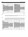
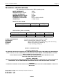
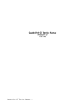
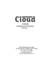
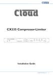
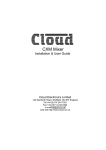
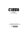
CX335
Technical Manual
Cloud Electronics Limited
140 Staniforth Road, Sheffield, S9 3HF England
Tel + 44 (0) 114 244 7051
Fax + 44 (0) 114 242 5462
e-mail [email protected]
web site http://www.cloud.co.uk
CX335 Technical Manual
Page 1
CX335 STEREO COMPRESSOR LIMITER
OPERATION and SERVICE GUIDE
CONTENTS
SECTION 1
"...where angels fear to tread"
Soft Knee, Fast Time Constants
Hard Knee, Fast Time Constants
Intelligent Limiting
Soft Knee, Slow Time Constants
Hard Knee, Slow Time Constants
SECTION 2
Introduction
SECTION 3
Installation
Mounting
Audio connections
Power connection
see page 3
section 1.01
section 1.02
section 1.03
section 1.04
section 1.05
see page 7
see page 8
section 3.01
section 3.02
section 3.03
SECTION 4
Compression and Limiting
see page 9
What is a compressor / limiter?
section 4.01
Threshold explained
section 4.02
What is Hard-knee and Soft-knee?
section 4.03
Ratio explained.
section 4.04
What about Attack and Release controls?
section 4.05
Gain requirements
section 4.07
Understanding Compressor Limiters verses Peak-limiting section 4.08
Other nomenclature
section 4.09
SECTION 5
Control Descriptions
Slow (Attack & Release) Switch
Hard (Knee) Switch
Threshold Control
Ratio Control
Peak Limiter Control
Gain Control
Bypass Switch
Gain Reduction Displays
Output Meter Displays
SECTION 6
Operation
Useful hints and tips
SECTION 7
Circuit Description
The Audio Path
The Side Chain
The Displays
The Power Supply
Remote Control
SECTION 8
Access for Service
see page 11
section 5.02
section 5.01
section 5.03
section 5.04
section 5.05
section 5.06
section 5.07
section 5.08
section 5.09
see page 14
see page 15
section 7.01
section 7.02
section 7.03
section 7.04
section 7.05
see page 16
Page 2
CX335 Technical Manual
SECTION 9
Audio Calibration
STATIC TESTING
Initialise Control settings
Operating D.C. Voltages
VU meters
Set 0dB level
Set Total Harmonic Distortion (THD)
Peak Control
Compression Laws
Re-check levels
DYNAMIC OBSERVATIONS
Test tone sequences
Dynamic Control settings
Program dependant waveforms (Hard compressor)
Program dependant waveforms (Slow compressor)
Program dependant waveforms (Soft compressor)
Program dependant waveforms (Peak limiter)
section 9.09
section 9.10
section 9.11
section 9.12
section 9.13
section 9.14
Technical Specification
see page 21
Safety Considerations
see page 21
Circuit Diagrams
see page 17
section 9.01
section 9.02
section 9.03
section 9.04
section 9.05
section 9.06
section 9.07
section 9.08
at rear of manual
© Cloud Electronics Ltd, Sheffield, England
CX335 Technical Manual
1
Page 3
"... where angels fear to tread."
OK. It's 6.30pm, and the unit has just been delivered, and the Club opens tonight! Rather
than read the whole manual you can take this short-cut route, but be it on your own head.
Connect the unit into the signal path directly after the system mixing desk or DJ console,
and just before any amplifiers or cross-over.
If your system runs balanced then used balanced XLR leads, with the standard
configuration of:
Pin 2 hot (positive phase); Pin 3 cold (negative phase); Pin 1 ground (screen).
If you are configured 'unbalanced' then we suggest that for all XLR plugs and sockets
connected into the CX335 each Pin 3 should be shorted to Pin 1. Do this, even if you are
in a hurry.
If you are running a mono system you will have to connect input signal to both channels
using some form of 'Y' lead to be able to make any sense of the front panel meter scales
and control graticules.
We have carefully optimised the front panel by removing most of the controls and made
the circuitry 'Programme Dependant'. This wonderful phrase denotes some clever
electronics which are described later in the manual. To simplify setting up the front panel
controls the possible permutations of switches and controls can be grouped into four
'categories', each 'category' having different audio results. The settings for the front panel
can be grouped into the four following 'categories':
Soft Knee, Fast Time Constants - Ultra transparent Control of Sound Pressure Level
(SPL) and speaker protection.
Hard Knee, Fast Time Constants - Transparent and precise control of signal level and
speaker protection.
Soft Knee, Slow Time Constants - Very transparent control of SPL with more peaks
allowed through unprocessed.
Hard Knee, Slow Time Constants - The least transparent mode of operation to reduce
high level signals but with more peaks passed unprocessed.
Soft Knee, Fast Time Constants
This is the recommended mode of operation, yielding the most musical results with the
least perceptible manipulation of the audio signal!
0dB
RELEASE
KNEE
HARD
3
2
-15
5
+10
SLOW
-10
-20
THRESHOLD
MAKE EQUAL TO
BYPASS LEVEL
ROTATE UNTIL LED FLASHES
AT DESIRED PEAK OUTPUT
ROTATE UNTIL -15 TO -10dB
BELOW SIGNAL INPUT
10
5
1.5
1.2
RATIO
COMPRESSING
BELOW 10:1
-2
-4
0
15
6
3
20 0
10
8
1.01
20
26
-6
PEAK
4
4
8
8
12 dB 12
GAIN
BYPASS
LIMITING
ABOVE 20:1
Do not depress the Hard or Slow switches. Set the Threshold to somewhere between
10dB and 15dB LOWER than your average input level and set the Ratio control
somewhere between 5:1 and 10:1, if you require compression of the audio signal, but
20:1 or higher if you require compression and limiting.
Page 4
CX335 Technical Manual
With normal programme level running through the CX335, rotate the Gain control so that
the output level on the Left and Right channel VU meters measures about the same in
Bypass mode as it does with the Compressor operational. Then rotate the Peak Limiter
control to a position where the peak LED only flashes occasionally to capture very high
level peaks for speaker protection. Normally this will be at a level just below the clip level
of the following amplifier with programme passing though the unit at full level.
With this configuration, the louder the input then the more compression will take place. A
distinguishable increase in average overall volume should be noted, although the peak
output level should be slightly lower.
1.02
Hard knee, Fast time constants
This mode of operation will be slightly more noticeable (especially with high Ratio
settings) as the point where compression takes effect is at a definite audio level.
BELOW 10:1
ABOVE 20:1
ROTATE UNTIL LED FLASHES
AT DESIRED PEAK OUTPUT
ROTATE UNTIL -15 TO -10dB
BELOW SIGNAL INPUT
RELEASE
KNEE
HARD
3
2
-15
5
+10
SLOW
-10
-20
THRESHOLD
10
5
1.5
1.2
RATIO
COMPRESSING
BELOW 10:1
-2
-4
0
15
6
3
20 0
10
8
0dB
20
26
-6
PEAK
MAKE EQUAL TO
BYPASS LEVEL
4
4
8
8
12 dB 12
GAIN
BYPASS
LIMITING
ABOVE 20:1
Depress the Hard switch. Set the Threshold to somewhere between 5dB and 8dB
LOWER than your maximum input level. Set the Ratio control at about 5:1 or even higher,
if you require compression of the audio signal, but 20:1 or higher if you require
compression and limiting. The higher the ratio the more audible the compression will be!
Set the Peak Limiter to a position where the pointer reads a similar value to the maximum
audio input. Turn the Gain control so that the output level on the VU meters measures
about the same in Bypass mode as it does with the Compressor operational.
With this configuration, quieter signals should pass through the compressor unprocessed, (no Gain Reduction taking place) but louder input signals above the Threshold
level will have a significant amount of compression (many LEDS lit on the Gain Reduction
meter). The Peak Limit LED will flicker ON more often than would normally be expected,
especially with very percussive tracks at high level. No perceived effect will be noticed
until very high input levels are used, then the CX335 will take control to preserve system
integrity and prolong the life of the audiences' hearing.
1.03
Intelligent Limiter
Due to the programme dependant nature of the compressor section and its split
frequency stereo side chain, the preferred method of limiting is to use the compressor
section with a ratio of infinity to 1.
Depress the Hard switch. Set the Threshold to the level where limiting is to commence.
Set the Ratio control fully clockwise. Set the Peak Limiter to a position where the pointer
reads a similar value to the maximum level permissible before any following amplifiers will
clip. This should be higher than the compressor limiter threshold by several Dbs. Turn the
Gain control so that the output level on the VU meters measures about the same in
Bypass mode as it does with the Compressor operational.
With this configuration, quieter signals will pass through the compressor un-processed,
(no Gain Reduction taking place) but louder input signals above the Threshold level will
CX335 Technical Manual
Page 5
SET TO CAPTURE VERY HIGH
PEAK TRANSIENTS
ROTATE TO DESIRED
LIMIT LEVEL
RELEASE
KNEE
HARD
3
2
-15
5
+10
SLOW
-10
10
5
1.5
1.2
-20
-2
-4
20
4
4
8
8
26
-6
12 dB 12
PEAK
RATIO
THRESHOLD
0
15
6
10
3
20 0
8
0dB
MAKE EQUAL TO
BYPASS LEVEL
BYPASS
GAIN
LIMITING
ABOVE 20:1
have a definite maximum output level that will never be exceeded (many LEDS lit on the
Gain Reduction meter). The Peak Limit LED should never flicker if it is set correctly and
providing that the Gain control is not adjusted too high.
1.04
Soft Knee, Slow Time Constants
This mode of operation will still yield musical results, but will tend to allow the very quick
dynamics through unprocessed. Therefore you will require more peak limiting and a high
overhead in speaker power handling.
Depress the Slow switch. Set the Threshold to somewhere between 10dB and 15dB
LOWER than your average input level and set the Ratio control somewhere between 5:1
and 10:1, if you require compression of the audio signal, but 20:1 or higher if you require
compression and limiting.
With normal programme level running through the CX335, rotate the Gain control so that
the output level on the Left and Right channel VU meters measures about the same in
Bypass mode as it does with the Compressor operational.
Rotate the Peak Limiter control to a position where the peak LED flashes quite often to
capture very high level peaks for speaker protection. The Peak Level is best adjusted by
monitoring or observing the amplifier peak or clip indicator with full level programme
passing through the unit.
ROTATE UNTIL LED FLASHES
AT DESIRED OUTPUT
ROTATE UNTIL -15 TO -10dB
BELOW SIGNAL INPUT
RELEASE
KNEE
HARD
3
2
-15
5
+10
SLOW
-10
-20
THRESHOLD
10
5
1.5
1.2
RATIO
COMPRESSING
BELOW 10:1
-2
-4
0
15
6
3
20 0
10
8
0dB
SWITCH
DEPRESSED
20
26
-6
PEAK
MAKE EQUAL TO
BYPASS LEVEL
4
4
8
8
12 dB 12
GAIN
BYPASS
LIMITING
ABOVE 20:1
With this configuration, the louder the input then the more compression will take place. A
perceived increase in average overall volume should be noted, although the peak output
level should be slightly lower. Some dynamics might cause other problems further down
the signal path.
1.05 Hard knee, Slow time constants
This mode of operation will be the most noticeable (especially with high Ratio settings
and fast dance tracks) as the point where compression takes effect is at a definite audio
level.
Page 6
CX335 Technical Manual
ROTATE UNTIL LED FLASHES
AT DESIRED PEAK OUTPUT
ROTATE UNTIL -8 TO -12dB
BELOW SIGNAL INPUT
RELEASE
KNEE
HARD
3
2
-15
5
+10
SLOW
-10
-20
THRESHOLD
10
5
1.5
1.2
RATIO
COMPRESSING
BELOW 10:1
-2
-4
0
15
6
10
3
20 0
8
0dB
20
26
-6
PEAK
MAKE EQUAL TO
BYPASS LEVEL
4
4
8
8
12 dB 12
GAIN
BYPASS
LIMITING
ABOVE 20:1
Depress the Hard and Soft switches. Set the Threshold to somewhere between 5dB and
8dB LOWER than your maximum input level. Set the Ratio control at about 5:1 or even
higher, if you require compression of the audio signal, but 20:1 or higher if you require
compression and limiting. The higher the ratio the more audible the compression will be!
Set the Peak Limiter to a position where the pointer reads a similar value to the maximum
audio input. Turn the Gain control so that the output level on the VU meters measures
about the same in Bypass mode as it does with the Compressor operational.
With this configuration, quieter signals should pass through the compressor unprocessed, (no Gain Reduction taking place) but louder input signals above the Threshold
level will have a significant amount of compression after the initial peak is passed
unprocessed. The Peak Limit LED will flicker ON often, especially with very percussive
tracks at high levels.
Reserve some time to read the rest of this manual.
CX335 Technical Manual
Page 7
Introduction
The Cloud CX335 Stereo Compressor Limiter has been designed to provide all the
functional needs of the system installation engineer with a desire to perform signal
levelling and overload protection. The unit can be applied equally to any discotheque or
live installation as well as in the recording studio and mastering facility.
Historically, it has often been impossible to establish what time constants are to be
applied to a compressors's attack and release envelope when the signal dynamics are an
unknown quantity. The CX335 has intelligent 'Programme Dependant' circuitry which
makes the need for attack and release controls totally redundant. Other features include
the options of hard-knee or soft-knee characteristics, a fully controllable 'Instant-attack'
Peak Limiter, accurate and informative metering, and remote control of the compressor
side chain.
The CX335 may be used in either balanced or unbalanced systems with no internal reconfiguring.
Because the CX335 compressor offers a choice of traditional hard-knee, ratio style
compression or soft-knee compression, it is equally adept at creative work and
unobtrusive level control. With high ratio settings the compressor can perform the
functions of an intelligent programme-dependent limiter.
The control layout is simple and logical. For reasons that will become evident, the unit is
graduated assuming that of a hard-knee ratio style compressor, although the default (and
suggested) mode of operation is soft-knee where the transition from unity gain to gain
reduction at the selected ratio is progressive and occurs over a nominal 10dB input level
range. In other words, in soft-knee mode with high ratios, the unit will blend from gentle
compression up to hard limiting with no additional front panel adjustment.
Soft-knee compressors are often chosen in applications that call for less conspicuous
level control whereas ratio type hard knee compressors are generally considered more
successful where large amounts of gain reduction are required. By offering both
alternatives, the CX335 is capable of outstanding results in a very wide range of
discotheque, studio and live sound situations.
Compressors are often accused of dulling the sound being processed, and a little
explanation is needed to understand exactly why that is. What happens is that bass or
low frequency sounds, which contain most of the energy in a typical piece of music,
cause a normal compressor to apply gain reduction, and so any quieter, high frequency
sounds occurring at the same time as the bass sound will also be turned down in level.
This is why the cymbals and hi-hats in a heavily compressed track seem to dip in level
whenever a loud bass drum or snare drum beat occurs. The 'intelligent' side-chain of the
CX335 will attempt to overcome this by sensing the input frequency of the signal and
adjusting itself accordingly.
A feature of the CX335 is a highly effective peak limiter which allows the user to set an
absolute output level that can never be exceeded. This facility is extremely valuable for
speaker driver protection. With correct Threshold and Ratio adjustments the compressor
section can be set to act as a primary level controller with the Peak Limiter set above this
to perform secondary security.
Page 8
CX335 Technical Manual
Installation
3.01
Mounting
The CX335 is designed for standard 19" rack mounting and occupies 1U of rack space.
Avoid mounting the unit directly above power amplifiers or power supplies that radiate
significant amounts of heat and strong magnetic fields. Fibre or plastic washers may be
used to prevent the front panel becoming marked by the mounting bolts.
3.02
Audio Connections
Both the input and output 3pin XLR connectors may be used either balanced or
unbalanced, the wiring convention being: pin 2 hot, pin 3 cold and pin 1 ground. For use
with unbalanced systems, unbalancing can be achieved by shorting pin 3 of the XLR
connectors to ground (pin 1) at both inputs and outputs. In both modes of operation the
system input level should be referenced to 0dBu.
The CX335 is designed as a stereo compressor and always expects to be used with
matching left and right stereo signals. Unexpected and unusable results will occur if two
independent mono signals are fed through the unit. Furthermore, if the audio system
being processed is configured for mono operation you will have to connect an input signal
to both channels to make any sense of the front panel meter calibration and control
graticules, although only one output socket need be used.
If earth loop problems are encountered, do not disconnect the mains earth but instead,
operate the system in the balanced mode with the cable screen only connected at the
receiving end of the cables. If the system can only be operated in the unbalanced mode,
then we suggest that all items of equipment be supplied from power sockets in close
proximity to each other, and if equipment is fitted with earth switches or links/jumpers,
then these should be switched off or the links removed.
Under no circumstances must any earth connections be removed.
3.03
Power Connection
The unit will have been configured to operate on a power input of 220 to 240 Volts AC at
40 to 60Hz. If for some reason the unit is to be used at a mains input operating voltage
which is different to that as supplied, the following procedure must be carried out. (see
following diagram)
1: Disconnect the unit from the mains.
2: Using a number 2 size pozidrive screwdriver, remove the six self-tapping screws
retaining the top panel of the unit.
3: Using a number 1 size pozidrive screwdriver, remove 4 M3 machine screws that retain
the main PCB to the bottom panel. These can be located:
3.1: Just behind the Threshold control
3.2: Directly behind the Gain Reduction display meter.
3.3: In front and to the rear of the grey encapsulated transformer block.
4: From the underside of the unit, remove the six self-tapping screws retaining the bottom
panel of the unit, using the number 2 pozidrive.
5a: If the unit is currently configured for 220-240 Volts AC, to the side of the transformer
can be found 1 zero Ohm link. This should be removed and two zero Ohm links should be
fitted to the positions marked 110-120 Volts. Go to paragraph 6.
5b: If the unit is currently configured for 110-120 Volts AC, to the side of the transformer
can be found 2 zero Ohm links. These should be removed and one zero Ohm link should
be fitted to the position marked 220-240 Volts.
6: Replace the power fuse with a correctly rated fuse for the new operating voltage.
7: Re-fit the two covers in the reverse order.
CX335 Technical Manual
Page 9
VOLTS
OPERATION
FIT TWO
LINKS FOR
110/120
TRANSFORMER
120V
TRANSFORMER
HIGH VOLTAGE
VOLTS
OPERATION
HIGH VOLTAGE
FIT ONE
LINK FOR
220/240
240V
120V
VIEW INSIDE CX335 SHOWING POSITION OF VOLTAGE SELECTION LINKS
COMPRESSORS and LIMITERS
4.01
What is a compressor / limiter?
Compression is an audio process that reduces the output progressively once the input
level has risen above a pre-settable threshold. Once this threshold level is exceeded then
the rate at which the output is reduced is controlled by a predictable rate, called 'ratio'.
Limiting is an extension of compression where once the threshold is exceeded, the output
level will not rise any further. Therefore limiting can also be perceived as a compressor
with its 'ratio' set higher than 20 to 1.
4.02
Threshold explained
As a rotary control, the threshold parameter is easy to understand. Threshold compares
the input level to the level set on the front panel. It is very common to see the graticule
around the threshold control marked from higher levels on the counter clockwise end to
lower input levels on the clockwise end. This is because more compression happens as
the control is turned 'up'.
4.03
What is Hard-knee and Soft-knee?
The actual threshold point where compression takes place is called the 'knee', the reason
being that if a graphical representation of input level verses output level is made, then
below threshold the line will be at 45° (output is the same as input). Above threshold this
line will have a gentler slope equal to the ratio setting. So the line will have a definite 'fold'
or 'knee'. (see following diagram).
With high ratio settings this knee can be very noticeable. To prevent this sudden change
between no compression below threshold and lots of compression above threshold, it is
much gentler on the ear if this knee is 'rounded' or softened. Soft-knee is more musical
and desirable if the actual compression process is not to be too obtrusive. So by default,
the CX335 compressor limiter is a 'soft-knee' device, yet still can be overridden by use of
the Hard switch.
Page 10
CX335 Technical Manual
INPUT
IN dBs
GRAPH OF INPUT LEVEL
VERSES OUTPUT LEVEL
NO COMPESSION
+10
+5
HARD KNEE
0dB
RATIO 10:1 OR LESS
-5
-10
SOFT KNEE
THRESHOLD
LIMITING
-15
RATIO 20:1 OR GREATER
-20
-25
-30
OUTPUT IN dBs
-30
4.04
-25
-20
-15
-10
-5
0dB
+5
+10
Ratio explained.
For a hard-knee compressor, the effect of Ratio can be easily understood by
remembering that ratio is a comparison between input levels and output levels. For
instance; a ratio setting of 3:1 results in only 1dB of change at the output for every rise in
input level by 3dB providing that the input is greater than the threshold setting. A simple
rule of reading Ratio settings can be input:output, or input rise of xdB gives output rise of
ydB. For a soft-knee compressor, the Ratio control becomes a little less well defined
Soft-knee gradually changes the ratio as the signal rises above the threshold setting. On
the CX335 this change takes place for as much as 10dBs, so the selected ratio is only
reached once the signal is 10dB above the threshold setting. This changing ratio is far
more musical and disguises the fact that any manipulation of the dynamic range is taking
place.
4.05
What about Attack and Release controls?
The rate at which the compressor takes effect (once the threshold is exceeded) is called
Attack, similarly the rate at which the compressor subsides (after the input signal falls
below threshold) is called Release. The wrong attack time for a compressor will have
different poor results for differing input frequencies. For instance too fast an attack time
with low frequencies will cause distortion as the gain reduction changes during one cycle,
on the contrary, too slow an attack time on high frequencies will not process the signal
peaks quick enough, resulting in the possibility of system clipping and lack of speaker
protection.
The conclusion is, that for broad-band music programme a fixed attack time is virtually
useless. Similarly a release control that doesn't track the input programme envelope will
result in audible 'pumping' or breathing as the gain reduction changes. The CX335 gets
over this problem by constantly adjusting these two crucial 'parameters' internally
depending on the level and frequency of the incoming signal. For this reason the Attack
and Release controls have been removed from the front panel.
4.06
Gain requirements
When the signal exceeds threshold and the compressor takes effect, there will be a
reduction in the real output 'volume'. This volume reduction is made back-up to the
original level with the Gain control. In normal use, the average amount of level reduction
shown on the gain reduction meter, will be the position to where the Gain control is
rotated positively. A point to note is that this gain is applied to all signals, whether above
or below any thresholds, so quiet sounds will be louder by the amount of gain make-up,
even the residual background system noise!
CX335 Technical Manual
4.07
Page 11
Understanding Compressor Limiters verses Peak limiting
Due to the range of the ratio control, the compressor can be set up to perform as a very
effective limiter. Further-more, with its soft knee operation, the characteristics of the unit
blend from gentle compression for signal just above threshold, through to hard limiting.
The intelligent control circuitry and programme dependent attack and release make the
audible effect almost un-noticeable. This compressor limiter section should not be
confused with the Peak limiter in the CX335. This is intended to be used as a system
failsafe for any high peaks that are still quite high even after some compression has
occurred.
For example; with signals above the compressor threshold, if the ratio is set to 3:1 and
the input rises by +15dB there will still be a +5dB rise at the output. This rise might cause
a system overload, except this can be trapped by the Limiter section providing the Peak
Limit threshold is correctly adjusted. The optimum use of the Peak Limiter is when used in
this method. It is difficult to give a generalisation for limiter threshold settings as many
factors govern this value:
Firstly, how much level can be sent from the mixing console? In a well configured system
this will average around 0dB, but with only slightly too much gain at each mixing stage
this level can soon rise far higher. The Peak limiter can be set to capture this overload.
Secondly, how much signal is required by the amplifier or crossover inputs? If the Peak
Limiter is set too high then any peaks allowed through the CX335 might cause input
distortion or overload to the following amplifier. It is more likely that the amplifiers will clip
before the output signal clips
4.08
Other nomenclature.
Side-Chain
- The control circuit that decides how much gain reduction to apply
at any one instant, depending on the input level and the front panel controls is called the
side-chain. In a standard compressor the circuitry only has two main sections: the audio
path and the side chain.
Gain Reduction
- The difference between the measured output level after the
compressor taken effect and the level that would be output if no processing was
happening.
Controls
5.01
Slow switch:
This push switch modifies the programme-dependant circuitry to allow fast dynamic
peaks through unprocessed, yet still monitor and control level when the input is above the
threshold for periods of a second or more. If this switch is depressed it is strongly advised
that the Peak Limiter should be used as an additional trap to capture very loud and quick
dynamic peaks.
5.02
Hard switch:
Modifies the Knee of the compressor by affecting the Ratio control so that gain reduction
takes place linearly once the threshold level is exceeded. It is strongly advised that the
unit be configured in its intended mode of Soft-knee for a more transparent compression.
5.03
Threshold:
Determines the input level above which gain reduction will be applied and may be set in
the range +10dB to -20dB. This control graticule is accurate for compression with the
Hard switch depressed. In the native soft-knee mode, compression takes place gradually
once the threshold is just exceeded. The amount of compression rises, until the input
signal reaches approximately 10dB above the threshold setting, where upon conventional
compression is applied at the amount dictated by the Ratio control.
Page 12
CX335 Technical Manual
RELEASE
KNEE
5.04
HARD
2
-15
5
+10
SLOW
-10
-20
THRESHOLD
3
10
5
1.5
1.2
RATIO
-2
-4
0
15
6
10
3
20 0
8
0dB
20
26
-6
PEAK
4
4
8
8
12 dB
GAIN
12
BYPASS
Ratio:
With the Hard switch depressed, this control governs by how much the input level must
rise before a rise of 1dB would be seen at the output. For example, (In Hard-knee mode)
With the input signal level above the threshold setting, a Ratio setting of 5:1 would imply
that the output would only rise by 1dB with a 5dB rise in the input level.
With the compressor set for soft-knee, Ratio fixes the final compression ratio that will be
applied once the 10dB 'soft-knee' region is exceeded. The ratio may be continuously
adjusted from 1.2:1 to infinity:1 allowing the possibility of true hard limiting.
5.05
Gain:
The output level may be attenuated or amplified by up to 12dB to compensate for level
changes caused by compression and limiting. Quite often compressors are perceived to
'reduce' the total output level, this control should normally be adjusted so that the output
level measures identical levels on the VU meters with Bypass depressed and released.
The Gain control can also be set audibly if the system speakers are within unobstructed
ear-shot. Normally this control will be operated rotated to the positive (clockwise) gain
side.
This control comes before the Peak limiter detector and this fact should be taken into
account when setting the Peak limiter threshold.
5.06
Peak Limit:
Sets an absolute limit to the level that the output signal will not be permitted to exceed.
The control ranges from +26dBu (where the limiter has no effect) down to -6dBu. This
limiter is very fast acting enabling it to control any peaks without audible distortion. If the
output signal is so high as to cause the limiter to operate for more than 20mS, the system
gain is automatically reduced to bring the signal back within range. The system gain is
then returned to normal over a period of approximately one second. The peak limit control
and the compressor Gain control should be used in conjunction to ensure that the peak
limiter operates only rarely (if at all), if it is to be used purely for peak protection.
Alternatively, it may be deliberately driven into limiting by falsely increasing the gain
control to produce creative effects.
5.07
Bypass:
This switch causes a bypass of all signal processing, where the input signal is routed
directly to the output socket. Normally the switch is used to compare the raw unprocessed
signal against the effects of any compression and or limiting.
CX335 Technical Manual
Page 13
OUTPUT DISPLAY
GAIN REDUCTION
30 20 15 10
6
4
2
L
1
0dB
-20 -16 -12 -8 -4 0dB +4 +8 +12
R
5.08
Gain Reduction Meter:
A nine segment LED bargraph meter continuously monitors the gain reduction applied by
the compressor and or limiter and even any remote control voltage over the range 0 to
30dB. The amount of gain reduction shown is greatly affected by all of the front panel
controls. Due to the transparent action of the compressor, more activity will probably be
shown than is audibly evident. It is anticipated that the 30dB LED will seldom illuminate
even in abuse conditions.
5.09
Output Level Meters:
These are nine segment LED bargraph level meters that monitor the level of the two
output signals over the range -20dB to +12dB with reference to the 0dBu operating level.
With average stereo programme these will track together. Vastly differing levels will most
likely be a cable short or external system configuration fault.
Page 14
CX335 Technical Manual
Operation
The unit should be connected in line with the stereo signals to be processed either by
breaking the existing connection between mixer console and cross-over or amplifiers or
via suitable insert points on the master outputs of the console, (if such exist).
Setting up the front panel controls is easiest if the Peak Limiter threshold is initially set to
maximum. This allows the compressor to be set up in isolation. The ratio setting depends
on how firmly the signal dynamics need controlling; as a rule, higher ratios provide a
higher degree of control but also tend to be more audible in operation when high levels of
gain reduction are required. The integral soft-knee feature of the CX335 renders these
effects far less pronounced, but this factor should still be taken into consideration when
setting up. Although, a higher compression ratio may be used than on a conventional
compressor without compromising the sound quality.
Adjust the Threshold control until the desired amount of gain reduction occurs. This is
judged partly by ear and partly by observing the gain reduction meter. In general, a
maximum gain reduction of between 6dB and 10dB will be adequate. When in the soft
knee mode, you will notice that the threshold control is rotated more clockwise than would
normally be expected.
Set the Gain control to give the required output level using the level meter to guide you.
Additional assistance can be obtained by alternately selecting Bypass mode and normal
compressor operation, in both modes the optimum Gain setting will give equal output
levels on the meter, but a slight increase in the 'music power' with the compressor
operating. Avoid running at very high output levels as this reduces the available amount
of signal head room and could lead to distortion in extreme cases.
Once the gain is correct, set the Peak Limiter Level control so that the limiter LED only
lights briefly on extreme signal peaks. Alternatively, set the Peak limiter Level to the
desired maximum output value and then adjust the compressor Gain control to ensure
minimum limiter activity. One major use of the peak limit control is to prevent input
distortion or clipping on the following amplifiers. If only peak limiting is required then we
suggest setting the compressor ratio to greater than 1:30, the compressor threshold to at
least 12dB lower than the normal input level and using the soft-knee mode as opposed to
using the peak limiter alone.
The Peak limiter has no separate on / off control, but turning the Peak Level control fully
clockwise will prevent any unwanted limiter action. To effectively bypass the compressor
section turn the compressor Threshold up to its maximum of +10dB (fully
counter-clockwise) and set the Ratio to its lowest setting of 1.2:1 although we do not
recommend using the peak limiter without the support of the compressor section.
CX335 Technical Manual
Page 15
Circuit Description
For clarity the internal circuitry of the CX335 is best described in sections. Both left and
right audio inputs are passed through a Voltage Controlled Amplifier (VCA) to the
balanced output sections; a signal level detector below 200Hz; a signal level detector
above 200Hz ; peak limiter detector; display circuits
7.01
The Audio Path
Due to the fact that both Left and Right channels are basically identical, only one channel
is described here. Any component references are given for the Left channel with the Right
channel in parentheses.
Signals are fed into an electronically balanced input opamp IC1a (IC6a) with a gain of
-6dB. The output of this opamp drives three routes:One route is to the Bypass switch where it can be connected directly to the output stage.
One route is into the side chain filters (described later.)
One route is to the Voltage Controlled Amplifier (VCA).
An industry standard high performance VCA is used to increase or decrease gain, IC3
(IC8). The VCA used is the dBX 2150A and the device has a current output which can be
measured with an oscilloscope on pin 1 of IC1b (IC6b). The gain of the VCA is controlled
by a DC voltage onto pin 3. Note: If pin 3 is grounded, then signal is passed with no gain.
This factor can be a useful service aid.
The VCA feeds a Peak Limit rectifier IC13a (IC17a) and passes into the Peak Limit
comparator IC4a (IC9a), where the signal level is compared with a DC voltage derived
from the front panel potentiometer VR3. This sets the bias level for two high speed
diodes D6 & D7 (D16 & D17) that will clip off any signal peaks greater than the bias.
Clipping causes IC4a (IC9a) to generate charge pulses to the limiter control voltage
IC19b and IC13b, this circuit is common to both audio channels ensuring no stereo image
shift. The Peak / Limiting LED indicator driven by IC19a is lit when audio peaks cause
limiting, and not illuminated during the limit envelope.
The Bypass switch selects the input signal buffer or the signal from the peak limiter and
feeds this to the balanced output stage IC5 (IC10) which has gain of +6dB.
7.02
The Side Chain
The signal from the input stage is passed through the 200Hz high-pass filter (HPF) IC2a
(IC7a). This is summed with an anti-phase signal from IC2b (IC7b) to produce a low-pass
filter (LPF) output of signals below 200Hz. For each audio input there are two signals
which are converted to DC using log law dual detectors, SSM2120, where IC12 is
configured to process the HPFs and IC16 is processing the LPFs. The LPF outputs of
these detectors are summed and passed to the threshold/ratio circuit which in turn feeds
the long time constant attack and release circuit and the HPF outputs are summed and
sent to the threshold/ratio circuit feeding the short time constant attack and release
circuit.
The Threshold potentiometer VR1 sets a DC bias to IC11a for the HPF and IC15a for the
LPF, this determines the signal level that will cause compression. This level is then
amplified by the Ratio stage IC15b for LPF and IC11b for HPF. The ratio amplifier has a
gain of 10 when 'Hard' is selected adjustable by presets PR7 and PR8, and an antilog
response with a maximum gain of 10 when 'Soft' is selected. The antilog element uses a
pair of transistors T3/T4 for LPF and T1/T2 for HPF, which are biased into the log part of
their curve by presets PR9 and PR6.
The DC control voltages from these stages are divided by the Ratio potentiometers VR2,
which feeds the LPF and HPF envelope attack and release circuits. The LPF envelope
circuit using IC21a, IC22a and IC22b has a slow attack with a 50mS hold and a
programme dependant decay. The HPF envelope circuit using IC20a and IC20b has a
much faster programme dependant attack, no hold and a programme dependant decay.
Page 16
CX335 Technical Manual
The term 'programme dependant' means that when a large, fast transient occurs the
circuits charge and discharge more rapidly.
The two LPF and HPF control voltages are Or'd with the output from the limiter and the
output from the remote control sensor circuit to produce a common control line IC14a. For
troublesome faults, each control voltage can be isolated at the input of IC14a by
progressively isolating the following diodes: Limiter via D9, HPF control via D8, LPF
control via D11 and any remote control via D12. The output of IC14a has a preset to
compensate for component tolerances and is summed with a DC voltage derived from the
Gain control VR4. This Gain control supplies 0 Volts for 0dB gain, a preset for each
channel adjusts this voltage exactly to match the detent in the rotary gain control and
compensate for any component mis-match in the audio path.
7.03
The Displays
The three display meters are very similar in design. All LED meters are driven from a
constant current source restricted to 8mA. For the two VU displays, the outputs from the
bypass switches are rectified using IC28 (IC23). This rectified voltage is then
progressively compared to a resistor ladder calculated to give an accurate VU display.
The gain reduction display voltage is derived from the output of IC14a post preset PR5.
Note that the tally LEDs are driven in series with the right channel VU and gain reduction
meter displays, should any one LED be open circuit then neither meter bargraph will
function.
7.04
The Power Supply
The CX335 has a standard bi-polar 15-0-15 Volt power supply derived from two
adjustable regulators. This enables a smooth power-on as the reference pins of the
regulators are slowly established by capacitors C58 and C55.
7.05
Remote Control
It is possible to control the CX335 compressor side chain with an external remote voltage.
The VCA control pins can be driven remotely by a DC voltage. A factory built unit will
normally be configured so that +15V input will result in 56dB of gain reduction, but this
can easily be reconfigured by changing the gain around IC17b. The 9pin 'D' socket also
has voltage points to be able to fit a potentiometer or another circuit, depending on
installation requirements. Note that provision in the PCB is made for additional noise
immunisation using an inductor, removing R73 and fitting RCMAN (100k Ω). This control
is a specialised operation and is intended for future expansion of CLOUD products and
interfaces.
Access for Service
The CX335 compressor limiter be accessed for servicing by the following method:
1: Disconnect the unit from the mains.
2: Using a number 2 size pozidrive screwdriver, remove the six self-tapping screws
retaining the top panel of the unit.
3: Using a number 1 size pozidrive screwdriver, remove 4 M3 machine screws that retain
the main PCB to the bottom panel. These can be located:
3.1: Just behind the Threshold control
3.2: Directly behind the Gain Reduction display meter.
3.3: In front and to the rear of the grey encapsulated transformer block.
4: From the underside of the unit, remove the six self-tapping screws retaining the bottom
panel of the unit, using the number 2 pozidrive.
5: Extreme caution should now be taken before any power is re-applied to the CX335 as
many live and high voltage points can easily be touched.
CX335 Technical Manual
Page 17
Removal of the smaller display Printed Circuit Board should only be necessary if there is
a display fault. Viewing the unit from above, remove the 2 M3 machine screws to free the
display board from the supporting pillars. Take care not to strain the jumper cable.
Audio Calibration
Internal adjustments of the CX335 will not need any attention. However if component
changes have been made, it may be necessary to adjust one or more of the pre-set
potentiometers. To adjust the presets you will require an adjustable level, balanced test
sine wave signal of two differing frequencies, we suggest 100Hz and 1kHz, initially set to
a line level of +0dBu (0.775V RMS). You will also require an accurate VU measuring
meter (with adjustable, or automatic, gain make-up) and an oscilloscope.
Static testing - where all levels can be measured.
9.01
The front panel of the unit must be initially adjusted as follows:Both Slow and Hard switches released. (Out).
Compressor Threshold rotated fully Counter Clockwise to '+10dB'.
Compressor Ratio rotated fully Counter Clockwise to '1.2:1'.
Peak Level setting rotated fully Clockwise to '+26dB'.
Output Gain set initially to '0dB'. (In its detent).
Bypass / Normal initially set to 'Bypass'. (In).
The following series of tests will ensure all the features of the CX335 are operating
correctly. In most cases, the conditions for each test should be continued into the
following test. Consequently, it is suggested that all tests should be carried out in the
numbered sequence.
9.02
Due to the fact that many of the internal presets and front panel controls are referenced to
the voltage supply rails, it is prudent if the actual voltages and condition of the rails are
measured. The outputs of the regulator IC31 (LM317) should be at +15 Volts and
regulator IC32 (LM337) -15 Volts. Any discrepancy from these voltages should be equally
balanced when compared to ground, ±0.25 Volts. A difference of greater than 0.5 Volts
may cause some presets to have insufficient range.
Ensure no noise or RF interference is present on either rail.
Also, ensure that the input to IC14a pin3 does not have any positive offset voltage; a
negative offset of no more than 100mV is better. The closer to 0Volts this point measures,
the easier calibration will be.
9.03
Insert a 1KHz +0dBu balanced test signal into both channels. With the Bypass switch
pressed in, ensure that the LED meters up to the 0dB LED, just illuminates. If one (or
both) doesn't, try increasing the input test signal level by no more than 0.3dB. If the 0dB
LED still doesn't illuminate then rectify the fault in the display circuit(s). Re-select 'Normal'
operation. Increase the Gain control fully clockwise until the +12dB LEDs illuminates. (All
the LEDS in the meter should be illuminated at this point). Similarly decrease the control
observing a linear decrease in both meters
9.04
0dB (set true zero dBu, presets marked PR2 for the left channel and PR4 for the right
channel) With bypass depressed, ensure that 1KHz 0dBu is input to both channels and
0dB can be measured at both outputs. Ensure that the Gain control is centralised in its
detent. Release the bypass switch and observe 0dBu signal at both outputs. Adjust the
respective preset to correct any discrepancy in either or both channels.
Page 18
CX335 Technical Manual
9.05
THD (Total harmonic distortion, Presets marked PR1 for the left channel and PR3 for the
right channel). No adjustment should be made to the THD presets without the use of an
accurate THD meter. Correct adjustment will leave the preset approximately central about
its track. A level of 0.015% distortion or lower can be expected (especially if the bottom
panel is still attached to the unit).
9.06
Apply +20dB input level. Rotate the Peak Level control counter clockwise whilst observing
the output level. Note that the Limit LED will start to illuminate at the onset of limiting (ie
as the control passes through the +20dB graticule). The output level should continuously
decrease as the control is slowly rotated, until a point were -6dB output level can be seen
when the control is fully counter clockwise. The Gain Reduction meter should be
illuminated up to the 20dB LED when this condition is applied.
9.07
COMPress, SOFT law & HARD law (Presets marked PR5, PR6, PR9 and PR7, PR8).
Because of the interactivity of the presets in this section, they have been grouped
together into one test. However, things are not as daunting as might be as presets PR6
and PR9 only apply to frequencies over 200Hz, (calibrate using 1KHz) and presets PR7
and PR8 apply to signal frequencies lower than 200Hz (calibrate using 100Hz or lower).
To commence these tests, the Hard and Slow switches must be released. Apply
maximum Compressor ratio and threshold (both clockwise).
Reduce the input level to -20dB. Observe the following readings at the output when the
test signal level is adjusted in 10dB increments and ensure the GR meter on the front
panel tracks accordingly:
INPUT LEVEL
READ EXTERNAL VU
METER (APPROX)
-20dB
-10db
0db
+10db
+20db
-20db
-14dB
-10dB
-10dB
-10dB
VOLTS @ D8 ANODE
FOR HIGH
FREQUENCIES
300mV
1.2 V
2.9 V
5.0 V
7.25 V
VOLTS @ D11 ANODE
FOR LOW
FREQUENCIES
420mV
1.5 V
3.1 V
5.0 V
7.0 V
The most important measurement using the above table should be the output level
remaining constant when +10dB and +20dB input level is applied. The table above shows
this level should give a reading -10dB. The amount of compression law can be adjusted
with preset PR5. Use preset PR6 to adjust the point at which compression 'levels off' with
high frequency input, and PR9 for low frequency input (-10dB in the above table).
Depress the Hard switch. Step the input signal level between -20dB and +20dB in four
10dB increments, whilst adjusting PR7 for high frequencies and PR8 for low frequencies
to show no output level change at all. Mis-alignment might cause 'fold-over', where the
output starts to decrease as input signal increases. The actual level will vary from unit to
unit but should be in the region of -21dB to -25dB. More importantly is that the constant
output level should be similar for both low and high frequencies.
With the Hard switch still depressed and a Ratio setting of 2:1 the following input and
output levels should be seen:
For an input of -20dB, read -20dB at the output.
For an input of 0dB, read -10dB at the output.
For an input of +20dB,
read 0dB at the output.
CX335 Technical Manual
Page 19
9.08
Re-check the 0dB level as per test number 9.04 for both channels. If there is a large
discrepancy, then the calibrations described in 9.07 will need to be re-run.
Dynamic Observation - where the oscilloscope displays are subjective.
9.09
For the dynamic observations listed in section 9.09 and onwards, you will need test signal
bursts or 'sequences' set to three different levels, and available at two different
frequencies. For factory calibration the two signal sequences are as follows:Tone sequence one:
A signal of 0dB at 1KHz for a period of 300ms; immediately followed by a signal of -15dB
at 1KHz for a period of 300mS; then a synchronisation period of silence again for 300mS.
Tone sequence two:
A signal of 0dB at 80Hz for a period of 500ms; immediately followed by a signal of -15dB
for a period of 500mS; then a synchronisation period of silence again for 500mS.
The silence period in each sequence should hopefully provide enough of a level change
for the oscilloscope to trigger reliably, providing enough signal level offered to the
oscilloscope.
9.10
Due to the CX335 front panel control ranges having an important effect on the audio
signal, it is important that the test equipment and controls are set very similarly to the
following descriptions. It is possible that any discrepancy will produce a vastly different
oscilloscope display, which might mislead or confuse the final tests and observations.
The front panel of the unit must be initially adjusted as follows:Slow switch released. (Out).
Hard switch depressed. (In).
Compressor Threshold rotated fully Counter Clockwise to about '-8dB'. (This being
midway between the two test sequence levels of 0dB and -15dB)
Compressor Ratio rotated fully Clockwise to infinity to 1.
Peak Level setting rotated fully Clockwise to '+26dB'.
Output Gain set so that the test sequence displays full scale during the 0dB level section
of the sequence, taking care that if any rotation away from the detent is required, then this
Gain make up amount should be a positive value, otherwise the later Peak observations
will be incorrect, as Peak will be ineffective.
Bypass / Normal released. (Out).
Set the oscilloscope as follows :Input gain to display 0.5 Volts / div (D.C. coupled)
Timebase to 20mS / div (or slower if more screen persistence is available). The
representations of the oscilloscope displays (fig 9.01 / 9.04) have being shortened in time
during the linear part of the wave so that the envelope seems to appear on one timebase
'pass' of the display. In reality the test sequences necessitate that two 'passes' of the
display are required to view the whole envelope.
9.11
Apply the 1KHz test sequence as described above. The waveform in fig 9.01 can be seen
at the output, verifying the correct operation of the timing circuits in the HF section of the
side chain. The attack portion of the waveform should respond somewhere in between
25mS and 30mS. The release section taking upwards of 150mS.
9.12
Press the Slow switch, note the changes to the output in fig 9.02. The attack and release
times will be greatly extended. (Attack 200mS or more , Release greater than 600mS) ,
as shown in the diagram fig 9.03.
Page 20
Fig 9.01
CX335 Technical Manual
Fig 9.02
9.13
Release the Hard and Slow switches, ensure that envelope changes in level, and that the
time constants are slightly different from that in section
9.14
Check the program dependant attack of the Peak Limiter with controls as above, (both
Hard and Slow switches released) and gradually decreasing the Limit level to observe the
output shown in fig 9.04, (this being extremely dependant on the output Gain setting).
Fig 9.03
Fig 9.04
CX335 Technical Manual
Page 21
TECHNICAL SPECIFICATIONS
(All measurements referenced to 0dBu operating level)
10kΩ
+26dBu
80 Ω
+26dBu
600Ω
20Hz to 20kHz ±0.5dB
<-70dB 10kHz
INPUT IMPEDANCE
MAXIMUM INPUT LEVEL
OUTPUT IMPEDANCE
MAXIMUM OUTPUT LEVEL
MINIMUM OUTPUT LOAD
FREQUENCY RESPONSE
CROSSTALK
NOISE AT UNITY GAIN
22Hz - 22KHz
-90dB
CCIR ARM
-90dB
IEC A
-92dB
DISTORTION (THD and NOISE)
Unity Gain, 0dBu
+10dBu input 10db Gain Red
POWER REQUIREMENTS
FUSE RATING
FUSE TYPE
CASE SIZE
WEIGHT
100Hz
<0.03%
<0.1%
1KHz
<0.02%
<0.1%
10KHz
<0.03%
<0.1%
110-120 Volt or 220-240 Volt at 40-60Hz, 15 Watts
100mA for 220-240 Volts, 200mA for 120 Volts
20mm x 5mm, Class 3 type 'T' (time delay), 250 Volts working
482mm (w) x 44mm (h) x 155mm (d)
3.4 Kgs (including packaging)
SAFETY CONSIDERATIONS
CAUTION - MAINS FUSE
TO REDUCE THE RISK OF FIRE REPLACE THE MAINS FUSE ONLY WITH THE SAME TYPE, WHICH MUST
BE A CLASS 3, 240 VOLT, TIME DELAY TYPE, RATED AT 100mA WHERE THE MAINS INPUT VOLTAGE
SWITCH IS SET TO 220-240 Volts AC.
FOR A MAINS VOLTAGE OF 110-120 Volts AC. THE FUSE SHOULD BE RATED AT 200mA
THE FUSE BODY SIZE IS 20mm x 5mm.
CAUTION - SERVICING
THIS UNIT CONTAINS NO USER SERVICEABLE PARTS. REFER ALL SERVICING TO QUALIFIED SERVICE
PERSONNEL. DO NOT PERFORM ANY SERVICING UNLESS YOU ARE QUALIFIED TO DO SO.
WARNING
TO REDUCE THE RISK OF FIRE OR ELECTRIC SHOCK DO NOT EXPOSE THIS EQUIPMENT TO RAIN OR
MOISTURE.
This product conforms to the following European Standards
BS EN 50081-1: 1992
BS EN 50082-1: 1992
BS EN 60065 : 1994
17/01/01