1
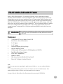
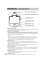
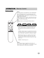
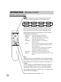
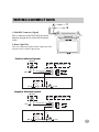
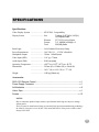
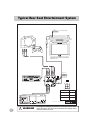
®
TMX-R700A
Mobile Overhead Monitor
OWNER’S MANUAL
PUSH
!
WARNING
It is dangerous and illegal for the driver to watch the TV/Video while
driving the vehicle. The driver may be distracted from looking ahead
and an accident could occur.
Caution
• Read this manual thoroughly before starting installation and operation. You will find a number of Safety Warnings
in this manual to tell you about things that could hurt you or other people if you were to ignore the Warnings. We
cannot be responsible for problems resulting from failure to observe the Warnings in this manual.
• This manual uses a symbol to show how to use this product safely and to avoid harm to yourself and others and
damage to your property. Here is what this symbol means. Understanding it is important for reading the Manual.
• Meaning of Symbol:
!
2
WARNING
This symbol means there is something that could cause serious injury or
death to you or other people.
DO NOT DISASSEMBLE OR ALTER
Attempts to disassemble or alter this product can lead to accidental fires or electrical shock.
KEEP SMALL ARTICLES OUT OF THE REACH OF CHILDREN
Keep small articles (wire-ties, etc.) out of reach of children. If swallowed, consult a physician immediately.
USE ONLY IN CARS WITH A 12 VOLT NEGATIVE GROUND
Use only in cars with a 12 volt negative (–) ground electrical system. (Check with your dealer if you are not sure.)
Failure to do so may result in fire, etc.
BEFORE WIRING, DISCONNECT THE CABLE FROM THE NEGATIVE BATTERY TERMINAL
Before doing any electrical wiring, disconnect the cable from the negative (–) terminal of the battery. Failure to do so
may result in electric shock or injury due to electrical shorts.
KEEP ELECTRICAL CABLES TOGETHER TO AVOID OPERATING HAZARDS
Dress the wiring to keep them from interfering with the operation of the steering wheel, gear lever, brake pedals, etc.
DO NOT CUT AWAY ANY WIRE INSULATION TO USE ITS POWER FOR OTHER EQUIPMENT
Tapping power from wiring to supply voltage to another piece of equipment could exceed the current carrying
capacity of that wire. This could result in fire or electric shock.
DO NOT INSTALL IN LOCATIONS WHICH MIGHT HINDER VEHICLE OPERATION
Do not install in locations which might create hazards for the vehicle occupants or hinder vehicle operation (such as
the steering wheel or gear shift) by obstructing forward vision or hampering movement etc.
DO NOT DAMAGE PIPES OR WIRING WHEN DRILLING HOLES
When drilling holes in the chassis for installation, take precautions so as not to contact, damage or obstruct pipes,
tanks or electrical wiring. Failure to take such precautions may result in fire.
DO NOT USE NUTS OR BOLTS IN THE BRAKE SYSTEM FOR INSTALLATION OR GROUND
CONNECTIONS
Never use safety-related parts such as bolts or nuts in the steering or brake systems or tanks to make wiring
installations or ground connections. Using such parts could disable control of the vehicle and cause fire etc.
HALT USE IMMEDIATELY IF A PROBLEM APPEARS
When problems appear, stop using the system immediately and contact the dealer from whom you purchased the
equipment. Some problems which may warrant immediate attention include a lack of sound, noxious odors or smoke
being emitted from the unit, or foreign objects dropped inside the unit.
DO NOT OPERATE THE EQUIPMENT OR LOOK AT THE SCREEN WHILE DRIVING
Do not change settings while driving. If operation requiring a prolonged view of the display is required, stop the
vehicle in a safe location before attempting operation.
DO NOT INSTALL THE MONITOR NEAR THE PASSENGER SEAT AIR BAG
Ensure that the location chosen for the monitor does not interfere with the operation of the passenger seat air bag.
This will prevent the triggered air bag from launching the display towards passengers, possible causing injury.
HAVE THE WIRING AND INSTALLATION DONE BY EXPERTS
The wiring and installation of this unit requires special technical skill and experience. To ensure safety, always
contact the dealer where you purchased this unit to have the work done.
DO NOT INSTALL IN LOCATIONS WITH HIGH MOISTURE OR DUST
Avoid installing the unit in locations with high incidence of moisture or dust. Moisture or dust that penetrates into this
unit may cause smoke or fire.
MAKE THE CORRECT CONNECTIONS
Failure to make the correct connections can cause fire or accident to occur.
ARRANGE THE WIRING SO IT IS NOT CRIMPED OR PINCHED
Route the cables and wiring so as not to be crimped by moving parts like seat rails or to make contact with sharp
spots which could damage the wiring.
DO NOT RAISE THE VOLUME EXCESSIVELY
Keep the volume at a level where you can still hear outside noises while driving. Driving while unable to hear outside
sounds could cause an accident.
FEATURES/DESCRIPTION
Alpine’s TMX-R700 integrates a 7.0 inch color LCD panel, a newly designed two channel
selectable infrared transmitter for wireless headphones, triple video source selector with a newly
designed hide-away box for easier installation. Three A/V inputs on the TMX-R700 allow for easy
system building with Alpine premium video sources, such as its DVD-7996 in-dash DVD player,
DVA-5205 CD/DVD player, TCS-V430A TV tuner, DHA-S680 6-disc DVD changer Other thirdparty sources may also be connected. Alpine’s SmartViewTM Swivel mechanism allows the monitor
to swivel 30º left/right and to tilt, providing a 120º- wide viewing angle from the center and a
constant horizontal viewing angle for vivid picture quality and optimal viewing for all rear-seat
passengers.
!
WARNING
It is dangerous and illegal for the driver to watch TV/Video while driving any
vehicle. The driver may be distracted from looking ahead and an accident
could occur.
Features:
•
•
•
•
•
•
•
•
•
•
•
•
7 inch Wide TFT Active Matrix Color LCD
SmartViewTM Swivel Mechanism
3 A/V Inputs
1 A/V Output
On Screen Display for Easy Setup
Wireless Remote Control
CH Selectable IR Transmitter for IR Headphones (A/B/OFF)
Dual Wired Headphone Outputs
NTSC/PAL Compatibility
Dimmer Control
Hide Away Interface Module for Easy Install
Direct Fit To Alpine Overhead Console
Note:
If you have any questions regarding the application of this device, see your authorized Alpine
dealer.
It is recommended that this product be used with Alpine’s various Overhead Consoles. Your
authorized Alpine dealer will have more information on these products.
See page 10 for the Typical Rear Seat Entertainment System using the TMX-R700.
3
OPERATION - Overhead Monitor
PUSH
4
1
Dual Headphone Outputs (2)
2
SmartView™ Swivel Mechanism
3
LCD Monitor Panel
4
Monitor Open Button
5
Built-in Dome Light
6
Alpine Back-lit Logo
1) Dual Headphone Outputs
Two output jacks (mini-phono plug) are provided for wired headphones. Output level is adjusted
using the Volume UP/DN buttons on the remote control.
2) SmartView™ Swivel Mechanism
The design of this mechanism provides the rear seat passengers a stable picture, viewable from
many different angles. This system allows the LCD to tilt from 90 to 120 degrees in 10 degree
steps. At the same time, the LCD will maintain its horizontal view while being rotated from left
to right, up to 30 degrees, in 10 degree steps.
NOTE:
• The LCD will only close when rotation is at 0 degrees to prevent damage to the monitor.
• When rotating the monitor, use both hands on either side of the panel to ensure even pressure
on the mechanism. This will prevent damage to the SmartView™ Swivel mechanism.
• Make sure the panel is fully opened (90 degree position) before trying to rotate.
3) LCD Monitor Panel
This is a 7 inch, Widescreen TFT, Active Matrix LCD. In addition, an Infrared Wireless
Headphone transmitter is located on top of the LCD panel. When the monitor panel is closed, the
power is automatically turned off.
NOTE: Whenever the LCD Panel is opened from closed position or Ignition/ACC is ON at
opened position, the Main Power is turned on automatically.
4) Monitor Open Button
Press this button to release the Monitor Panel. The Panel will drop down slightly allowing you to
fully open to its 90 degree or greater position. To close, firmly press the LCD Monitor Panel
back up into the housing until a click is heard.
5) Built-in Dome Light
To replace the bulb, gently open the dome light lens from the front . Use a 12V, 5W bulb or
equivalent. (e.g. SYLVANIA DE3022)
6) Alpine Back-lit Logo
Blue, back-lit ALPINE logo will turn on when the overhead monitor main power is on.
OPERATION - Remote Control
REMOTE CONTROL
Power
Press this button to turn Main Power to the TMX-R700
ON or OFF (Ignition/ACC must be ON and the LCD
Panel must be open). Closing the LCD Panel turns Main
Power OFF automatically.
NOTE: Whenever the LCD Panel is opened from the closed
position or Ignition/ACC is ON at opened position, the Main
Power is turned on automatically.
Disp
Press this button to cycle through the display modes as
follows:
WIDE
CINEMA
ZOOM
NORMAL
WIDE: Normal images are expanded uniformly in the
horizontal direction and are displayed over the entire
screen.
CINEMA: Normal images are expanded in the horizontal
and vertical directions. The top and bottom of the image is
cut off. This mode is suited for 16:9 cinema size images.
ZOOM: Normal images are expanded in the horizontal
direction and are displayed over the entire screen. The
expansion ratio increases towards the right and left edges
of the screen.
NORMAL: Normal image (4:3)
Source
Press the Source button to toggle between the three A/V
sources (AUX1, AUX2 and AUX3). As you toggle, the source
will be displayed on the OSD (On Screen Display).
5
OPERATION - Remote Control
REMOTE CONTROL (continued)
Setup
Press the Setup button to make adjustments to the picture.
The various options will rotate in the following order.
CONTRAST
BR IGH T
CO LO R
TINT
RE SET
N TS C /PAL
IR C H
DIMMER
Once the parameter you want to change is on the screen, use
the Volume UP or DN buttons to increase or decrease the
level respectively. If no action is taken within 10 seconds
after making the selection or adjustment, the Setup mode is
ended and the OSD turns off.
CONTRAST:
BRIGHT:
COLOR:
TINT:
DIMMER:
IR CH:
NTSC/PAL:
RESET:
Adjust the contrast of the picture.
Adjust the brightness of the picture.
Adjust the color balance of the picture.
Adjust the tint of the picture.
Select the Dimmer level (ON/OFF),
Default: OFF
Select the Infrared frequency of the transmitter
for the wireless headphone SHS-N202 (A/B/
OFF). Default: A
This function allows building a dual monitor
system and each monitor displays and
broadcasts a different video source.
Select the Video system. Default: NTSC
Reset all selection and adjustment to the factory
default.
Mute
Instantly mute the wired headphones by pressing this button.
Pressing the Mute button again (or pressing either the Volume
UP or DN button) will return the volume to its original level.
Volume
Use the volume UP and DN buttons to increase or decrease
the wired headphone output levels. Pressing and holding
either button will increase or decrease the volume rapidly.
The volume function does not affect AUX A/V Output or the
Infrared Wireless Headphone.
Battery Compartment (AAA Battery x 2)
6
WIRING/CONNECTIONS
1
2
1. Mini-DIN Connector (Pigtail)
This is connected to the TMX-R700 Overhead
Monitor, through the 5m, Mini-DIN Extension
Cable.
2. Dome Light Wire
This wire connects the built-in Dome Light to the cable
from the vehicle’s Dome Light Switch.
Positive Switched System
TMX-R700
Female
Connector
Dome Light Locker SW
3P (ON-OFF-DOOR)
Constant +12V
+12V
Dome Light (Always ON)
To
Built-in Dome Light
Light
ToTMX-R700
TMX-R700 Built-in
GND
GND
(Always OFF)
ToToVehicle
Trigger
VehicleDoor
Door Trigger
Dome Light (Door)
Factory Dome Light Circuit
Cut
Factory Door
ajar switch or
Body Control
computer
GND
+12V
Negative Switched System
TMX-R700
Female
Connector
Dome Light Locker SW
3P (ON-OFF-DOOR)
Constant GND
+12V
GND
+12V
Dome Light (Always ON)
To
Built-in Dome Light
Light
ToTMX-R700
TMX-R700 Built-in
(Always OFF)
ToToVehicle
Trigger
VehicleDoor
Door Trigger
Dome Light (Door)
Factory Dome Light Circuit
Cut
Factory Door
ajar switch or
Body Control
computer
GND
+12V
7
WIRING/CONNECTIONS
3. 5m Mini-DIN Extension Cable
3
This cable is included. It is connected between the TMX-R700 display and the
Hide-Away Box (included).
Hide-Away Box
5
4
8
10
9
6
7
4. AUX A/V, Input 1
5. AUX A/V, Input 2
6. AUX A/V, Input 3
7. AUX A/V, Output
An auxiliary A/V output is provided to drive an external monitor. This signal mirrors what’s being
shown on the TMX-R700 display. The volume function does not affect the Auxiliary A/V Output.
8. Fuse (2 A)
9. Mini-DIN Connector
This is connected to the TMX-R700 Overhead Monitor through 5m Mini DIN Extension Cable
(included).
10. Power Supply Connector
11. ACC Power lead (Red)
8
To ACC power lead powered when engine key position is
ACC.
12. Ground lead (Black)
Connect the lead to a good chassis ground on the vehicle.
Make sure the connection is made to bare metal and is
securely fastened using the sheet metal screw provided.
13. Remote Out
The Remote Out wire connects to any ALPINE Mobile Video
product which has an external remote input function. For
example, products such as a DVD, VCR and TV Tuner.
13
Remote Out
White/Brown
12
11
ACC
GND
Red
Black
SPECIFICATIONS
Specifications
Video Display System .......................... NTSC/PAL Compatibility
Display Screen
.......................... Size
7 inches, 6.07”(W) x 3.43”(H)
16:9 Aspect Ratio
Element
Format
Total
Back Light
..........................
Power Requirement
..........................
Headphone Output
..........................
Video Input (DIN)
..........................
Audio Input (DIN)
..........................
Operating Temperature ..........................
Dimensions
..........................
..........................
Weight
..........................
TFT-LCD, Active Matrix
7.0”, 480(W) x 234(H) x 3
336,960 pixels
Cold Cathode Fluorescent Lamp
14.4 VDC (11 – 15 VDC allowable)
32ohm 100mW(max)
1.0V p-p 75ohm
2.0V rms (max)
+32 oF to +113 oF (0 oC to + 45 oC)
267mm (D) x 228mm (W) x 45mm (H)
10.51” (D) x 8.98” (W) x 1.77” (H)
1.02 kg (2 lbs 4 oz)
Accessories
RUE-4153 Remote Control ................................................................................ x 1
Power Supply Connector ................................................................................... x 1
AAA batteries ..................................................................................................... x 2
Velcro Tape ........................................................................................................ x 1
Screws ............................................................................................................. x 12
NOTES:
Due to continuous product improvements, specifications and design are subject to change
without notice.
The LCD panel is manufactured using an extremely high precision manufacturing technology.
Its effective pixel ratio is over 99.99%. This means that 0.01% of the pixels could be either
always ON or OFF.
9
Typical Rear Seat Entertainment System
White
To Vehicle Dome light
White
SP
Infrared Channel (IR CH) in the SETUP
menu set to "A"
IR Remote Out
Ground
Ignition
A
VIDEO
A
Front View
4
1
3
2
1 Ignition/Accessory
2 Ground
3 IR Remote Out
Red
Black
White/Brown
4 N/C
Specifications and design are s ubject to change without n otice
10
!
WARNING
It is dangerous and illegal for the driver to watch the TV/Video while
driving the vehicle. The driver may be distracted from looking ahead
and an accident could occur.
Dual Rear Seat Entertainment System
White
White
White
White
To Vehicle Dome Light
Infrared Channel
(IR CH) in the
SETUP menu
set to "A"
Infrared Channel
(IR CH) in the
SETUP menu
set to "B"
MONITOR 2
RESET
DVD
VCR
To Vehicle Dome Light
MONITOR 3
VIDEO
R
AUDIO
L
L
AUDIO
R
VIDEO
SP
AUX IN
MONITOR 1
VIDEO
L
AUDIO
REMOTE 2
R
REMOTE 3
DIVERSITY ANTENNA
1
POWER SUPPLY
2
3
4
/////ALPINEMULTI-ZONE AV CONTROLLER / TV TUNER
TCS-V430A
VIDEO
IR Remote Out
Ground
A
A
Ignition
A
Front View
1. Ignition/Accessory
2. Ground
3. IR Remote Out
4. N/C
4
1
3
2
Red
Black
White/Brown
Specifications and design are s ubject to change without n otice
!
WARNING
It is dangerous and illegal for the driver to watch the TV/Video while
driving the vehicle. The driver may be distracted from looking ahead
and an accident could occur.
R
ALPINE ELECTRONICS, INC.
Tokyo office; 1-1-8 Nishi Gotanda,
Shinagawa-ku, Tokyo 141-8501, Japan
Tel.: (03) 3494-1101
ALPINE ELECTRONICS OF AMERICA, INC.
19145 Gramercy Place, Torrance,
California 90501, U.S.A.
Tel.: 1-800-ALPINE1 (1-800-257-4631)
1-888-NAV-HELP (1-888-628-4357)
ALPINE ELECTRONICS OF CANADA, INC.
Suite 203, 7300 Warden Ave. Markham, Ontario
L3R 9Z6, Canada
Tel.: 1-800-ALPINE1 (1-800-257-4631)
ALPINE ELECTRONICS OF AUSTRALIA PTY. LTD.
6-8 Fiveways Boulevarde Keysborough Victoria 3173,
Australia
Tel.: (03) 9769-0000
ALPINE ELECTRONICS GmbH
Kreuzerkamp 7-11 40878 Ratingen, Germany
Tel.: 02102-45 50
ALPINE ITALIA S.p.A.
Viale C.Colombo 8, 20090 Trezzano
Sul Naviglio (MI), Italy
Tel.: 02-48 47 81
ALPINE ELECTRONICS FRANCE S.A.R.L.
98, Rue De La Belle Etoile, Z.I. Paris Nord II B.P.50016
F-95945, Roissy, Charles De Gaulle Cedex, France
Tel.: 01-48 63 89 89
ALPINE ELECTRONICS OF U.K., LTD.
13 Tanners Drive, Blakelands,
Milton keynes MK14 5BU, U.K.
Tel.: 01908-61 15 56
ALPINE ELECTRONICS DE ESPANÃ, S.A.
Portal De Gamarra 36, Pabollón 32
01013 Vitoria(Alava)-Apdo. 133, Spain
Tel.: 34-45-283588
Printed in Taiwan R.O.C