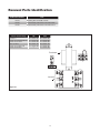
1
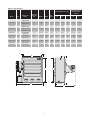
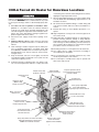
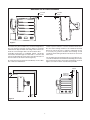
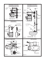
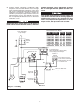
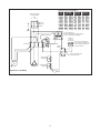
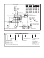
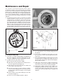
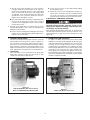
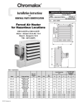
Installation and Operation
Instructions
CXH-A Forced-Air Heater
CXH-A-03 EP to CXH-A-35 EP
Class I - Groups C & D, Div. 1 & 2
Class II - Groups E, F & G
T3B - 165˚C (329˚F)
1
PF490-8
161-302421-004
July 2013
Table A - Specifications
Overall Dimensions (In.)
Voltage and
Phase
5/8” UNC Tapped
Mounting Hole
Locations
Horiz. Air
Discharge
(ft.)
BTUH
CFM
Wt.
(Lbs.)
A
B
C
D
E
Model
kW
CXHA-03
3
208/240V-1 or 3Ø
480/575V-3Ø
28
10,236
700
127
19-1/8
23-7/8
21
3-1/2
13-5/8
CXH-A-05
5
208/240V-1 or 3Ø
480/575V-3Ø
28
17,060
700
127
19-1/8
23-7/8
21
3-1/2
13-5/8
CXH-A-07
7.5
208/240V-1 or 3Ø
480/575V-3Ø
32
25,590
840
133
19-1/8
23-7/8
21
3-1/2
13-5/8
CXH-A-10
10
240V-1 or 3Ø
208/480/575V-3Ø
32
34,120
840
138
19-1/8
23-7/8
21
3-1/2
13-5/8
CXH-A-15
15
208/240/480V
575V-3Ø
47
51,180
1450
150
25
27-7/8
21
4-13/32
17-5/8
CXH-A-18
18
240V-3Ø
43
61,420
1400
165
25
27-7/8
21
4-13/32
17-5/8
CXH-A-20
20
480/575V-3Ø
43
68,240
1400
165
25
27-7/8
21
4-13/32
17-5/8
CXH-A-25
25
480/575V-3Ø
54
85,300
2330
200
32-1/8
31-7/8
21-3/4
5-1/2
21-5/8
CXH-A-30
30
480/575V-3Ø
54
102,360
2330
200
32-1/8
31-7/8
21-3/4
5-1/2
21-5/8
CXH-A-35
35
480/575V-3Ø
54
119,420
2330
200
32-1/8
31-7/8
21-3/4
5-1/2
21-5/8
2”
2”
E
D
A
A
11-1/16”
B
2
C
CXH-A Forced Air Heater for Hazardous Locations
overheating of the element and shutting down the unit by
tripping the high temperature cutout.
7. All unused threaded openings not used for supply wiring
must be fitted with threaded plugs approved for use in
hazardous locations.
Failure to understand and follow these installation instructions and the WARNING notes contained therein may result
in severe personal injury, death or substantial property damage.
8. All unit electrical installation fittings, conduit, wiring and
seals must meet NEC and local codes for hazardous locations.
1. To reduce the risk of ignition of hazardous atmospheres: In accordance with the National Electrical
Code, do not install where operating temperature code
exceeds the ignition temperature of the hazardous atmosphere. Use only in atmospheres having an ignition temperature higher than 165˚C (329˚F).
9. External line fusing or circuit breaker protection is required.
10.High temperature cutout(s) must never be bypassed in
the control circuit.
2. Disconnect from supply circuit before opening enclosures.
11.Alarm pilot lamp, if supplied, will turn on if the high temperature cutout(s) actuates. Steady on lamp indicates
temperature cutout(s) has tripped. This could result if the
heat exchanger is obstructed (dirty), inlet air restricted or
fan not turning. Shut off power to unit and refer to repair
procedures section of instruction sheet.
3. Hazard of Electric Shock. Heater must be effectively
grounded in accordance with N.E.C. to eliminate shock
hazard.
4. Heat exchanger contains Propylene Glycol under pressure at operating temperature. A material safety data
sheet (MSDS) is available from Chromalox upon request.
Should leakage occur, remove unit from service and investigate cause.
12. Mounting clearances on nameplate must be observed.
13.Use copper wire for supply connections according to
size and rating on nameplate.
14.Do not install any type of gasket material on any of the
electrical junction box cover surfaces.
5. Keep all electrical enclosure covers tightly closed and
secured with all bolts and threads. Cover joints must be
clean before replacing covers.
15.Do not attempt to override louver stops or operate unit
with louvers fully closed.
6. Install and operate in upright position only. Refer to Figure 3 for level requirements. Failure to comply will cause
Integral, heavy duty
magnetic contactor
Polyester powder-coated
heavy gauge steel corrosion
resistant cabinet
Mounting bolt
hanger connections
Explosion-proof
motor
Overpressure
protection device
Explosion-proof
(NEMA 7 & 9)
controls enclosure
Heavy gauge adjustable
louver with minimum
opening stops to direct air flow
Motor connections
wiring access
Removeable front cover
for ease of cleaning
Convenient terminal
block for room
thermostat protection
High efficiency heat
exchanger with integral
aluminum-finned steel tubes
Protective housing
for immersion heater
terminal enclosure
Heavy duty immersion heater assembly
with high temperature cutout(s) and
NEMA 7 & 9 terminal enclosure
Optional service light to
indicate when unit
needs servicing
Built-in 120V control
circuit transformer
(Optional 24V available)
3
General Information
The CXH-A series units rated 3 through 35 kW are designed
for operation in Class I, Div. 1, Groups C & D and Class II,
Div. 1, Groups E, F and G hazardous atmospheres having
an ignition temperature of 165°C (329°F) or higher. They are
designed for comfort heating and should not be operated in
ambient temperatures exceeding 40°C (104°F). All units in
Table A are UL listed.
Standard model CXH-A unit heaters are factory equipped
with an automatic reset type high temperature cutout.
The standard heater is designed to operate up to 7500
feet (2,286m) altitude. Consult factory for specific recommendations when using the units at higher altitudes.
The units are easily adapted for wall, ceiling or pole mounting. Refer to Figure 4 on Page XX for mounting information.
They are supplied with either 24 or 120V internal control circuit voltage. The heater is designed for use with an external
hazardous location thermostat or optional built-in thermostat.
Installation
The ceiling or wall mounting surface and the anchoring provision must be sufficient to support the combined weights of
the unit and mounting hardware.
FIRE/EXPLOSION HAZARD. Mount only in upright position and observe nameplate mounting clearances.
If using mounting hardware or a supporting structure not
supplied by Chromalox, the unit should be suspended from
the supporting structure thru the two mounting points on top
of the unit with 5/8 NC bolts and lockwashers. If single point
mounting is desired, order the correct size Chromalox adapter bracket (P/N
Heater Location instructions:
Arrange units so their discharge air streams:
A. are subjected to a minimum of interference from columns, machinery and partitions.
B. wipe exposed walls without blowing directly at them.
027-302361-001 for 12” fan units, P/N 027-302361-002 for
16” fan units) and P/N 027-302361-003 for 20” fan units. This
bracket is designed to hold the unit over its center of gravity
with a 1 dia. bolt. The maximum tilt angles as shown in Figure
3 must not be exceeded in either direction during operation
and installation. Failure to comply will cause high limit shut
down.
C. are directed away from room occupants in comfort heating.
D. are directed along the windward side when installed in a
building exposed to a prevailing wind.
Locate thermostat on interior partition walls or posts away
from cold drafts, internal heat sources and away from heater
discharge air streams.
EXPOSED
ED
EXPOS
EX
PO
D
D
SE
PO
EX
SE
PO
EX
Small rooms can be heated by one unit heater. Where two
walls are exposed, the heater should be mounted as shown
in Figure 2. Large rooms require multi-unit installations. Number and capacity of units will be determined by volume of
building and square feet of floor area to be heated. Arrange
units to provide perimeter air circulation where each unit supports the air stream from another.
Figure 2
The CXH-A hazardous location heaters are designed for use
only in a permanently mounted upright position. We recommend the use of a mounting kit (ceiling, wall or pole) available
from Chromalox. (Figures 5, 6 and 7)
4
D
EXPOSE
SE
D
Maximum Out of Plane Allowance
1/2" Max
13mm
1/2" Max
13mm
Figure 3
The heaters may be mounted at any convenient height above
floor. The minimum spacings shown in Figure 4 should be
maintained to adjacent walls and ceiling. If floor heat is desired, do not mount higher than 8 to 10 feet above floor.
Heater may be mounted on a shelf or stand from the bottom.
Be sure that mounting clearances are maintained and that
bottom of unit has at least 1 clearance underneath it. This
is necessary for good air circulation and servicing of heat
exchanger. All mounting methods must allow for removal of
front cover.
Controlling thermostats to individual heaters should be
mounted at shoulder height on inside walls or columns and
clear of the discharge air stream of the unit. Allow at least 4 in
front of heater for air stream to discharge freely.
The mounting and anchoring provisions must take into account the unit vibration and cantilevered loading when wall or
pole mounted. One of the Chromalox mounting kits shown in
Figures 5, 6 and 7 must be used whenever possible.
Do not mount mercury type thermostat directly on unit, vibration could cause malfunction.
Installation Clearances
102mm
Min.
(4")
5/8 NC (2)
Thds. For
Mounting
102mm Min. (4")
Figure 4
204mm
Min.
(8")
5
2"
Wall Mount Kit
Model # WMB-12 12” Fan (3-10 kW)
Model # WMB-16 16” Fan (15-20 kW)
Model # WMB-20 20” Fan (25-35 kW)
12” Fan - 16-3/4”
16” Fan - 18-1/2”
20” Fan - 22”
Wall
Bracket
1”ø Hardware % Bolt
Single Point
Swivel Mount
Supplied
Pole or Wall Mount Kit
Model # PMB-12 12” Fan (3-10 kW)
Model # PMB-16 16” Fan (15-20 kW)
Model # PMB-20 20” Fan (25-35 kW)
Heater Mounting
Bracket Arm &
Hardware
1/2 ø Hardware
Not Supplied
Pole Support
Bracket
Single Point
Swivel 4”ø
Supplied
P
Adapter Bracket
Supplied
with 5/8 Bolts
Adapter Bracket
& 5/8 NC Hardware
Supplied
P
ø 3/8 Hardware
Cust. Supplied
5-1/2” - 12” Fan
5-1/8” - 16” Fan
6-3/8” - 20” Fan
Figure 5
CXH-03EP through CXH-10
CXH-10EP through CXH-20
CXH-25EP through CXH-35
ø 1/2 x 4” U-Bolts
& Hardware
Cust. Supplied
P=10”
P=11-1/2”
P=14-1/2”
Ceiling Mount Kit
Model # HMK-00
4-9/16
Swivel Ceiling
Hanger S/A &
Hardware
Cust. Supplied ø 1/2
Mounting Hardware.
Bracket Spacing suitable
for use with 4” U-Bolts
Pole Base
4-7/8
5/8” ø Hex Nuts
& Washers
Supplied for
Installation
Top & Bottom
6” Ref.
3-1/2” SCH. 40 Pipe
or 4” O.D. X .25 Wall
Tube Cust. Supplied
Length to Suit
3/8” ø Hardware
Required for
Mounting Cust. Supplied
ø 5/8 Rods Length
to suit 1” Min.
Threaded Ends
Customer
Supplied
Figure 7
Figure 6
CXH-03 through CXH-10
CXH-10 through CXH-20
CXH-25 through CXH-35
Electrical Components
P=10”
P=11-1/2”
P=14-1/2”
Unit Top View
Transformer
1” NPT
Jumper Wire
1” NPT
Top Line Supply
Entry
Pilot Lamp
(Opt.)
Contactor
1/2” NPT
Thermostat Entry
Heat
Exchanger
Wiring
Compartment
5/8-11 Threaded
Mounting Holes (2)
Figure 9
Figure 10
6
Wiring and Wiring Diagrams
Table B -Supply Wiring Requirements
Supply Wire
ELECTRIC SHOCK HAZARD. Disconnect all power
before installing or servicing heater. Failure to do so
could result in personal injury or property damage.
Heater must be installed by a qualified person in accordance with the National Electrical Code, NFPA 70.
ELECTRIC SHOCK HAZARD. Any installation involving electric heaters must be performed by a qualified person and must be effectively grounded in
accordance with the National Electrical Code to
eliminate shock hazard.
1. Loosen and remove bolts securing the main terminal
enclosure cover on side of unit. Connect heater to line
supply wires at the box lugs located on the contactor
according the voltage and frequency specified on the
nameplate (see Figure 9). Refer to the appropriate wiring
diagram which also appears on the inside cover of this
enclosure (see Table B and diagrams on page 6).
EXPLOSION HAZARD. Cover joints must be clean before replacing cover. Do not use any gasket material
on joint surfaces.
2. Use copper conductors only for supply wires. Refer to
nameplate and Table B for size and rating required.
3. Connect supply line ground conductor to the box lug
provided on the base plate below contactor input lugs.
4. The fan motor is factory wired at the same voltage, and
phase as the heating elements. All motors are thermally
protected and connected to the main supply contactor.
On three phase units, it is necessary to verify that the fan
rotation is correct. Air stream discharge must be out front
of unit. After connecting unit to line and closing all covers
tightly, energize unit momentarily. If air does not exit front
louvers, reverse any two supply leads at the box lugs on
the contactor or at the supply disconnect.
5. Either of two 1 NPT rigid conduit openings with integral
stops may be used for connection to supply line. (See
Figure 9 and 10 for locations) Use only NEC approval
hazardous locations means of wiring such as mineral insulated cable and fittings or rigid conduit and seal fittings
located as required by installation codes.
Model
kW
Phase
Volts
90˚C Size (ga)
Max Fuse
Amps
CXH-A-03
CXH-A-03
CXH-A-03
CXH-A-03
CXH-A-03
CXH-A-03
3
3
3
3
3
3
1
3
1
3
3
3
208
208
240
240
480
575
10
12
10
12
12
12
25
15
20
15
15
15
CXH-A-05
CXH-A-05
CXH-A-05
CXH-A-05
CXH-A-05
CXH-A-05
5
5
5
5
5
5
1
3
1
3
3
3
208
208
240
240
480
575
8
10
8
10
12
12
35
20
30
20
15
15
CXH-A-07
CXH-A-07
CXH-A-07
CXH-A-07
CXH-A-07
CXH-A-07
7.5
7.5
7.5
7.5
7.5
7.5
1
3
1
3
3
3
208
208
240
240
480
575
6
8
6
8
12
12
50
30
45
25
15
15
CXH-A-10
CXH-A-10
CXH-A-10
CXH-A-10
CXH-A-10
10
10
10
10
10
3
1
3
3
3
208
240
240
480
575
8
4
8
10
12
40
60
35
20
15
CXH-A-15
CXH-A-15
CXH-A-15
CXH-A-15
15
15
15
15
3
3
3
3
208
240
480
575
4
6
8
10
60
50
25
20
CXH-A-18
18
3
240
4
60
CXH-A-20
CXH-A-20
20
20
3
3
480
575
8
8
35
30
CXH-A-25
CXH-A-25
25
25
3
3
480
575
8
8
40
35
CXH-A-30
CXH-A-30
30
30
3
3
480
575
6
8
50
40
CXH-A-35
CXH-A-35
35
35
3
3
480
575
4
6
60
50
7. Installation must include appropriate over current protection devices (fusing or circuit breakers) as required by the
National Electric Code in the supply line to the unit. Refer
to nameplate for proper current ratings.
8. To operate heaters from an externally mounted hazardous location thermostat, a terminal block is provided for
connection (Figures 9 and 10). Remove the factory installed jumper across T2 and T3 on the terminal strip.
Wire the thermostat contact leads to these terminals. The
built in control transformer supplies the unit with either
24V or 120V for internal unit operation. This voltage will
appear across the thermostat contacts when they are
open. The minimum thermostat contact rating should be
1 amp @ 120 VAC. Refer to nameplate for control voltage
of unit. The 1/2 NPT conduit wiring entry on top of the
terminal enclosure should be used to wire the thermostat
to the heater (Figure 10).
EXPLOSION HAZARD. All unused conduit openings
must be fitted with plugs that are U.L. recognized
for use in hazardous locations.
6. Heaters may be provided with a built-in control switch
and/or thermostat. If not, they should be controlled by an
externally mounted disconnect switch and/or separately
mounted thermostat as shown in the appropriate wiring
diagram on page 6. In case of malfunction, the personnel
in the area should be aware of location of heater disconnect.
7
unit and investigate cause of abnormal operation.
Do not reenergize until the problem has been corrected.
9. Protection against overheating is provided by a high
temperature cutout located within the heat exchanger
wiring compartment. (Figure 9) Activation of the control
will open the control circuit and energize the pilot lamp (if
supplied). If normal airflow is restricted, or stopped, the
unit will be cycled off by the high temperature cutout. The
high temperature cutout is also designed to shut down
the unit completely if the fluid level is low or other heater
malfunction occurs.
Users should install adequate back-up controls and
safety devices with their electric heating equipment.
If the back-up controls are to be located in the hazardous area, they must be approved for use in the
class of location. Where the consequences of failure
may be severe, back-up controls are essential.
High Temperature cutout(s) must never be bypassed
in the control circuit. If the limit actuates, shut down
Transformer Color Code Tabulation
Refer to Nameplate
for Input Voltage
PRI
VOLT.
1PH
L1 L2
Optional
Disconnet
Switch
GND
Primary
H2
Contactor
L1
L2
120V SEC
24V SEC
LEAD CLRS. LEAD CLRS.
H1
H2
X1
X2
X1
X2
208
BLK
RED
BLK
WHT
YEL
BLU
240
BLK
ORG
BLK
WHT
YEL
BLU
380
BLK
VIO
BLK
WHT
YEL
BLU
415
BLK
YEL
BLK
WHT
–
–
415
BLK
BRN
–
–
YEL
BLU
480
BLK
BLK/RED
BLK
WHT
YEL
BLU
575/600
BLK
GRY
BLK
WHT
YEL
BLU
H1
Control Transformer
Refer to Nameplate for Primary (Input)
and Secondary (Control) Voltage.
Optional Aux. Cont.
R
PRI. XFMR
LEAD CLRS.
X2
Secondary
X1
Connect Thermostat Wires
to the Common and Normally
Closed Terminals of One Pole
on the Thermostat.
L3
Optional Alarm
Terminal
Block
Built-In or
External
Thermostat
T3
T2
T1
Auto Reset
High Limit
Motor
1PH
Manual Reset
High Limit
Elements
Optional
Diagram I - 1 PH Wiring
8
Remove this Wire when
Using Thermostat
Transformer Color Code Tabulation
PRI
VOLT.
Refer to Nameplate
for Input Voltage
1PH
L1 L2
Optional
Disconnet
Switch
PRI. XFMR
LEAD CLRS.
120V SEC
24V SEC
LEAD CLRS. LEAD CLRS.
H1
H2
X1
X2
X1
X2
208
BLK
RED
BLK
WHT
YEL
BLU
240
BLK
ORG
BLK
WHT
YEL
BLU
380
BLK
VIO
BLK
WHT
YEL
BLU
415
BLK
YEL
BLK
WHT
–
–
415
BLK
BRN
–
–
YEL
BLU
480
BLK
BLK/RED
BLK
WHT
YEL
BLU
575/600
BLK
GRY
BLK
WHT
YEL
BLU
Optional Aux. Cont.
GND
H2
Primary
H1
Control Transformer
Refer to Nameplate for Primary (Input)
and Secondary (Control) Voltage.
R
Heater
Contactor
Motor
Contactor
L2
L1
L2
X2 Secondary X1
Optional Alarm
L3
L1
Auto Reset Manual Reset
High Limit
High Limit
Built-In or
External
Thermostat
(Red)
Fan
Motor
1PH
Optional
Connect Thermostat Wires
to the Common and Normally
Closed Terminals of One Pole
on the Thermostat.
T3
T2
(Heat)
White
Elements
Diagram II - 1 PH Wiring with Fan Switch
9
T1
Remove this Wire when
Using Thermostat
Transformer Color Code Tabulation
PRI
VOLT.
Refer to Nameplate
for Input Voltage
H1
H2
X1
X2
X1
X2
BLK
RED
BLK
WHT
YEL
BLU
240
BLK
ORG
BLK
WHT
YEL
BLU
380
BLK
VIO
BLK
WHT
YEL
BLU
415
BLK
YEL
BLK
WHT
–
–
415
BLK
BRN
–
–
YEL
BLU
480
BLK
BLK/RED
BLK
WHT
YEL
BLU
575/600
BLK
GRY
BLK
WHT
YEL
BLU
Optional
Disconnet
Switch
H2
Primary
H1
Control Transformer
Refer to Nameplate for Primary (Input)
and Secondary (Control) Voltage.
Optional Aux. Cont.
R
Contactor
L1
L2
120V SEC
24V SEC
LEAD CLRS. LEAD CLRS.
208
3PH
L1 L2 L3
GND
PRI. XFMR
LEAD CLRS.
X2 Secondary X1
L3
Optional Alarm
Terminal
Block
Built-In or
External
Thermostat
Connect Thermostat Wires
to the Common and Normally
Closed Terminals of One Pole
on the Thermostat.
T3
T2
T1
Auto Reset
High Limit
Motor
3PH
Elements
Manual Reset
High Limit
Diagram III - 3 PH Wiring
Optional
10
Remove this Wire when
Using Thermostat
Refer to Nameplate
for Input Voltage
Transformer Color Code Tabulation
PRI
VOLT.
3PH
L1 L2 L3
Optional
Disconnet
Switch
Optional Aux. Cont.
GND
H2
Motor
Contactor
L2
L1
L2
H1
H2
X1
X2
X1
X2
BLK
RED
BLK
WHT
YEL
BLU
240
BLK
ORG
BLK
WHT
YEL
BLU
380
BLK
VIO
BLK
WHT
YEL
BLU
415
BLK
YEL
BLK
WHT
–
–
415
BLK
BRN
–
–
YEL
BLU
480
BLK
BLK/RED
BLK
WHT
YEL
BLU
575/600
BLK
GRY
BLK
WHT
YEL
BLU
Primary
H1
Control Transformer
Refer to Nameplate for Primary (Input)
and Secondary (Control) Voltage.
X2
Secondary X1
Optional Alarm
L3
120V SEC
24V SEC
LEAD CLRS. LEAD CLRS.
208
R
Heater
Contactor
PRI. XFMR
LEAD CLRS.
L1
Auto Reset Manual Reset
High Limit
High Limit
Optional
Built-In or
External
Thermostat
(Red)
Fan
Motor
3PH
Connect Thermostat Wires
to the Common and Normally
Closed Terminals of One Pole
on the Thermostat.
T3
T2
Elements
Heat
(White)
Diagram IV - 3 PH Wiring with Fan Switch
T1
Remove this Wire when
Using Thermostat
MODEL NUMBER DESCRIPTION
CXH-A
10
4
3
Heater Voltage
2 = 240V 6 = 575V
3 = 380V 8 = 208V
4 = 480V 9 = 600V
5 = 415V
Heating Element Rating
03 = 3.0 kW 18 = 18.0 kW
05 = 5.0 kW 20 = 20.0 kW
07 = 7.5 kW 25 = 25.0 kW
10 = 10.0 kW 30 = 30.0 kW
15 = 15.0 kW 35 = 35.0 kW
30
40
30 = 24V Controls
32 = 120V Controls
Phase
1 = 1 Phase
3 = 3 Phase
Electric Blower Unit Heater for Hazardous Locations
1
1
EP
Explosion Proof
1 = Ethylene Group C & D, E, F, G T3B
2 = Propylene Group C & D, E, F, G T3B 0 = No Options
3 = Ethylene Group C, D, F, G T3B
1 = 15 or 30 Amp Disconn. Switch
4 = Propylene Group C, D, F, G T3B
2 = 60 Amp Disconn. Switch
3 = Pilot Light
4 = Pilot Light and 30 Amp
00 = No Thermostat
Disconn. Switch
40 = Thermostat
5 = Pilot Light and 60 Amp
Disconn. Switch
6 = Summer Fan Switch
7 = Summer Fan Switch, Pilot Light
8 = Disconn. Switch with Summer
Fan Switch
9 = Disconn. Switch, Pilot Light
with Summer Fan Switch
11
Operation
2. The finned structure of the heat exchanger must be kept
clean and free of accumulated dust and dirt. The cabinet front panel is easily removed providing access to the
heater core for periodic cleaning.
EXPLOSION HAZARD. Heater should not be operated
in ambient temperature higher than 40°C (104°F) or
in atmospheres corrosive to the heater itself.
3. Unit should not be operated with louvers fully closed.
Mechanical stops are incorporated into the design of the
cabinet to limit the degree of closure. Do not force the
louvers beyond these stops.
1. The CXH-A unit heaters use a sealed water-glycol filled
heat exchanger. The electric immersion elements transfer
heat energy directly to the fluid generating a fluid/vapor
mixture which releases its heat energy to the finned radiator as it rises and recondenses back to the bottom
reservoir to be reheated. This cycle will continue as long
as fan forced air is available on the finned structure to
remove the heat to the airstream.
4. If specified, units are supplied with a built in alarm pilot
lamp which will energize if the high temperature cutout(s)
has a been activated. During unit startup, the lamp will
flash on momentarily to verify its operation.
Maintenance and Repair
Maintenance and repair MUST be perfromed by qualififed personnel only.
I. REPLACING THE HEAT EXCHANGER
EXPLOSION/ELECTRIC SHOCK HAZARD. Disconnect
all power before opening enclosure covers or servicing heater. Failure to comply could result in personal
injury or property damage.
BURN HAZARD. Be sure heat exchanger and fluid
has been allowed to cool to 110°F before proceeding.
1. Periodically inspect all electrical connections and terminals to avoid electrical wiring difficulties. Inspect all wiring for frayed or worn insulation.
1. Detach the cabinet front by removing screws from all
sides of unit and pulling cover forward off cabinet shell.
Detach bottom panel by removing two screws on each
side and two screws in the rear. Remove the electrical
control enclosure lid. Disconnect the heater and high limit
wires from the electrical control enclosure. Loosen electrical conduit union located between the heater housing
and the electrical control enclosure. Support the lower
end of the heat exchanger and loosen the three hex head
bolts which hold it to the sheet metal. Lower the heat
exchanger away from the sheet metal. Reverse the above
procedure when installing a new heat exchanger.
2. Periodically and before each heating season, clean the
finned heat exchanger and fan inlet with compresses
air, vacuum, or water jet. Be sure all electrical covers are
tightly closed.
3. If heat output seems to be low, check amperage draw on
each element. Compare measured values to the correct
currents as listed on the unit nameplate.
4. The thermally protected fan motor is permanently lubricated and sealed. No field servicing is required or should
be attempted. Replace only with a factory supplied identical motor. Failure to do so will void the factory warranty
and may expose the user to risk of ignition of hazardous
atmospheres.
II.
RESETTING OPTIONAL MANUAL
TEMPERATURE CUTOUT
RESET
HIGH
5. Check fan blade to be sure that set screws are tight and
there are no cracks or looseness in the blades. Use factory supplied replacement blade only.
EXPLOSION HAZARD. Be sure that all enclosure
covers are replaced and tightly closed before re-energizing unit after servicing electrical components.
6. Check for any sign of leaking from the heat exchanger.
Too little fluid will cause the high temperature cutout(s) to
trip.
High temperature cutout(s) must never be bypassed
in control circuit.
The factory must perform the replacement of the
immersion heater or high temperature cutout. The
heat exchanger seal must not be broken. Consult
factory for service.
7. The sealed heat exchanger contains a glycol/water solution of propylene glycol. Ethylene glycol is supplied for
arctic duty conditions only. Avoid contact with skin and
eyes. If ingestion should occur, seek medical attention
immediately. In case of eyes or skin contact, wash affected areas with large amounts of water. The MSDS (Material Safety Data Sheet) for these materials is available
upon request.
12
Maintenance and Repair
The occurrence of the manual reset limit control to trip is
an abnormal condition. Care should be taken to determine
the exact reason that the high limit control tripped. Possible
problem areas could be dirty heat exchanger, blocked air inlet or outlet, fan/motor malfunction, too high operating ambient, incorrect operating voltage, or leaking heat exchanger.
In the event that the heat exchanger is defective, it must be
replaced.
1. The manual reset limit control is located in the heating
element hazardous location enclosure on the heat exchanger which is covered by the sheet metal housing attached to the side of the unit. To gain access, remove the
four sheet metal screws holding the sheet metal cover in
place and unthread the cast aluminum enclosure lid. (See
Figure 11.) The manual reset limit control device has a
small reset button protruding from the center of its back
housing. Depress this button in to reset the control. Replace the aluminum enclosure lid and sheet metal cover.
Figure 12
5-3/4"
Figure 13
5-3/4"
G.Unthread union at motor wiring outlet nipple connection. Carefully lift the motor, fan blade, and guard off of
the cabinet.
H. Note position of fan blade on motor shaft. Loosen the
two set screws to remove the fan blade and key from
shaft motor.
I. Place guard and fan blade on replacement motor shaft
in same locations as original motor. Align key ways in
hub and shaft. Insert key flush with fan hub and tighten
the two hub set screws.
J. Feed motor wires back into conduit and reposition
motor back on unit. Center fan blade in opening and
rotate to be sure that it clears housing and guard.
K.Thread motor nipple connection into conduit union
and tighten (5 threads minimum). Replace bolts in motor base and reattach fan guard to back of housing
in four places. Recheck blade rotation and tighten all
hardware.
Figure 11
III. FAN MOTOR AND BLADE
1. The motor is a sealed unit that requires no lubrication. If
the motor is defective, it must be replaced with an original factory supplied motor. (See renewal parts section.)
2. To replace the motor, proceed as follows:
A. Disconnect the unit from power supply.
B. (Units with motor splice box) Remove 4 bolts and cover of motor splice box (See Figure 12).
C. (Units without motor splice box) Remove 16 bolts and
cover of main control enclosure.
D.Note wire connections for future reference and disconnect all wires leading to the motor. All motor wires
are permanently marked according to the nameplate
on the motor.
E. Remove 4 bolts in motor base holding it to rear cabinet shelf. See Figure 13.
F. Remove 4 screws holding fan guard to cabinet.
13
L. Trim all motor leads extending out of the conduit to
6 lengths. Strip off 3/8 of insulation at cut ends. Using the motor nameplate, previous notes, and marked
wires, reconnect the motor for the unit voltage rating
as indicated on the heater nameplate. Re-attach the
ground wire to the connection inside the enclosure.
Replace cover and tighten securely.
B.Loosen the four screws on the cabinet back holding
the fan guard in place.
C.Pull the motor to the rear extending the conduit connection at the electrical enclosure. Fan blade and hub
set screws can now be accessed by tilting the guard
rearward at top or bottom back over the motor shell.
IV. ELECTRICAL COMPONENT SERVICING
M.Check fan rotation by momentarily energizing the unit.
Air must exit at cabinet front. Reverse any 2 leads at
contactor or line supply disconnect to reverse rotation
of three phase motor.
EXPLOSION/ELECTRIC SHOCK HAZARD. Disconnect
all power before opening enclosure covers or servicing heater. Failure to comply could result in personal injury or property damage.
3. Removal of fan blade does not require that the motor
wiring be disturbed. To clean, service or change the fan
blade proceed as follows:
When provided, the following components are located in the
cast aluminum hazardous location enclosure. Remove cover
and retaining bolts to gain access the following items (See
Figure 16).
A. Remove the four carriage bolts holding the motor base
in place on the cabinet platform. Mark the platform to
reposition at same location.
1. CONTROL TRANSFORMER
This item is located in the electrical enclosure. It may be
replaced while in the enclosure. To service or replace remove the quick connect wires and mark their locations.
Remove two screws which hold the transformer in place.
Note transformer orientation and voltage labels on top.
Replace transformer in the same orientation and connect
wires. Replace the cast aluminum cover and bolt down.
2.CONTACTOR
This component can be removed from the base plate
while in the enclosure. Follow the same steps as indicated for the transformer replacement.
3. ALARM PILOT LAMP (OPTIONAL)
To replace the bulb, unscrew the red lens bezel while
holding the lock ring until disengaged. Avoid turning the
entire assembly which is held tight to the enclosure with
a locking nut on the inside of the enclosure. It must be
re-tightened if loosened before reuse. Replace the lamp
with a 656 type bulb at the correct control voltage for the
unit (120V or 24). Secure the lens cap (5 threads minimum) against the locking ring and tighten securely before reenergizing unit. Lamp should flash on momentarily
when unit is energized. See renewal parts section for part
number of replacement bulbs.
Figure 14
CXH-A with Built in Disconnect Switch
(Must use HMK-00 Ceiling Mounting Kit)
Figure 15
CXH-A with Built in Thermostat
14
Renewal Parts Identification
Publication Number
Title
PF458
Mounting Kits for Model CXH-EP
PF461
Material Safety Data Sheet Chromakool EG
PF462
Material Safety Data Sheet Chromakool PG
Electric Control Voltage
Contactor
Transformer 208/240/480 PRI
Transformer 575 PRI
Aux. Contactor
Transformer 380/415 PRI
Transformer CXH-B
24V
072-304551-002
315-304252-002
315-304252-005
072-304551-102
315-304252-006
—
120V
072-304551-008
315-304252-001
315-304252-003
072-304551-102
315-304252-007
315-304252-008
Transformer
Contactor
Figure 16
15
15
19
17
33
35
16
1
50
50
51
52
27
31
34
32
30
25
49
28
8
27
44
29
75
26
15
CO
15
6
62
10
12
Figure 17
16
9
Manufacturer Part Number Breakdown
(Located On Unit Nameplate)
CXH-A- h h - h h - h h - EP
Common Parts
Shown in Figure 17
Code CXHA-03,
05, 07 & 10
Item#
Description
Part No.
1
Panel wrapper
207-303891-001
6
Panel Bottom
207-303881-001
8
Panel Front
207-303883-001
9
Louver
182-303884-001
10 Washer Shoulder
328-302074-002
12 Spring
276-130368-001
14 Terminal Box Cover 080-302079-001
15 Screw 10-32
248-073662-002
16 Fan Blade
Consult Factory
17 Fan Guard
134-302063-004
25 Enclosure
347-304561-001
26 Bolt 3/8-16, 1.5 lg 345-075603-263
27 Washer flat
328-075528-085
28 Washer lock
328-075571-011
29 Hex Nut 3/8-16
200-075473-044
30 Plug conduit 1/2”
221-302180-001
31 Plug conduit 1”
221-302180-003
32 Union conduit 3/4” 354-302165-001
33 Union conduit 3/4” 354-302243-001
34 Conduit Box
Consult factory
35 Conduit 3/4”
Consult factory
44 Plug conduit 3/4”
221-302180-002
50 Bolt 5/16-18
345-075603-218
51 Washer
328-075571-010
52 Nut 5/16-18
200-075473-039
62 Cover Exp. Proof
080-042350-007
75 Conduit 3/4
069-115087-049
CXH-A-15,
18 & 20
Part No.
207-303891-002
207-303881-002
207-303883-002
182-303884-002
328-302074-002
276-130368-001
080-302079-001
248-073662-002
Consult Factory
134-302063-005
347-304561-001
345-075603-263
328-075528-085
328-075571-011
200-075473-044
221-302180-001
221-302180-003
354-302165-001
354-302243-001
069-304115-002
Consult factory
221-302180-002
345-075603-218
328-075571-010
200-075473-039
080-042350-007
069-115087-079
CXH-A-25,
30 & 35
Part No.
207-303891-003
207-303881-003
207-303883-003
182-303884-003
328-302074-002
276-130368-001
080-302079-001
248-073662-002
Consult Factory
134-302063-006
347-304561-001
345-075603-263
328-075528-085
328-075571-011
200-075473-044
221-302180-001
221-302180-003
354-302165-001
354-302243-001
069-304115-002
Consult factory
221-302180-002
345-075603-218
328-075571-010
200-075473-039
080-042350-007
069-115087-093
Optional Equipment
Optional Equipment Parts
Description
Thermostat
30 Amp Disconnect
60 Amp Disconnect
Pilot Light Ass’y 24V
Pilot Light Ass’y 120V
Pilot Lamp 24V
Pilot Lamp 120V
Part Number
300-113075-003
104-304328-001
104-304328-002
213-121103-017
213-121103-018
172-052561-004
172-052561-003
Motor, Element & Heat Exchanger Parts
Model
CXH-A-03-81
CXH-A-03-83
CXH-A-03-21
CXH-A-03-23
CXH-A-03-43
CXH-A-03-63
CXH-A-05-81
CXH-A-05-83
CXH-A-05-21
CXH-A-05-23
CXH-A-05-43
CXH-A-05-63
CXH-A-07-81
CXH-A-07-83
CXH-A-07-21
CXH-A-07-23
CXH-A-07-43
CXH-A-07-63
CXH-A-10-83
CXH-A-10-21
CXH-A-10-23
CXH-A-10-43
CXH-A-10-63
CXH-A-15-83
CXH-A-15-23
CXH-A-15-43
CXH-A-15-63
CXH-A-18-23
CXH-A-20-43
CXH-A-20-63
CXH-A-25-43
CXH-A-25-63
CXH-A-30-43
CXH-A-30-63
CXH-A-35-43
CXH-A-35-63
1/4 HP Motor
Item 19
193-302087-006
193-302087-007
193-302087-006
193-302087-007
193-302087-007
193-302087-008
193-302087-006
193-302087-007
193-302087-006
193-302087-007
193-302087-007
193-302087-008
193-302087-006
193-302087-007
193-302087-006
193-302087-007
193-302087-007
193-302087-008
193-302087-007
193-302087-006
193-302087-007
193-302087-007
193-302087-008
193-302087-007
193-302087-007
193-302087-007
193-302087-008
193-302087-007
193-302087-007
193-302087-008
1/2 HP Motors
193-302087-009
193-302087-010
193-302087-009
193-302087-010
193-302087-009
193-302087-010
Heat Exchanger*
Item 19
353-304167-001
353-304167-001
353-304167-002
353-304167-002
353-304167-005
353-304167-006
353-304167-008
353-304167-008
353-304167-009
353-304167-009
353-304167-012
353-304167-013
353-304168-001
353-304168-001
353-304168-002
353-304168-002
353-304168-005
353-304168-006
353-304168-008
353-304168-009
353-304168-009
353-304168-012
353-304168-013
353-304169-001
353-304169-002
353-304169-005
353-304169-006
353-304169-008
353-304169-012
353-304169-013
353-304170-003
353-304170-004
353-304170-008
353-304170-009
353-304170-012
353-304170-013
* For arctic duty conditions, heat exchanger with
ethylene glycol are required. Consult factory.
Mounting Kit Adapter
CXH-A-03 through 10
027-302361-001
CXH-A-15 through 20
027-302361-002
CXH-A-25 through 35
027-302361-003
The factory must perform the replacement of the
immersion heater or high temperature cutout. The
heat exchanger seal must not be broken. Consult
factory for service.
17
Limited Warranty:
Please refer to the Chromalox limited warranty applicable to this product at
http://www.chromalox.com/customer-service/policies/termsofsale.aspx.
1347 HEIL QUAKER BLVD., LAVERGNE, TN 37086
Phone: (615) 793-3900
www.chromalox.com
18
© 2013 Chromalox, Inc.