1
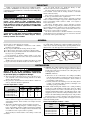
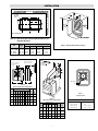
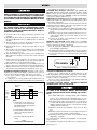
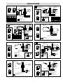
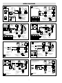
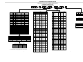
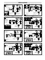
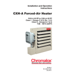
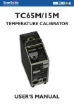
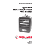
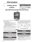
®
Chromalox
Installation
SERVICE REFERENCE
DIVISION
and
4
SALES
REFERENCE
RENEWAL PARTS IDENTIFICATION
SECTION
LUH
PF479-6
(Supersedes PF479-5)
161-303474-001
DATE
JANUARY, 2003
Type LUH
Horizontal Unit Heater
Specifications — Table 1
Electrical Data (60 Hz)
Dimensions (In.)
Model
LUH-D-02-81
LUH-D-02-21
LUH-D-02-71
LUH-D-04-81
LUH-D-04-83
LUH-D-04-21
LUH-D-04-23
LUH-D-04-71
LUH-D-04-43
LUH-D-05-81
LUH-D-05-83
LUH-D-05-21
LUH-D-05-23
LUH-D-05-71
LUH-D-05-43
LUH-D-07-81
LUH-D-07-83
LUH-D-07-21
LUH-D-07-23
LUH-D-07-71
LUH-D-07-43
LUH-D-10-81
LUH-D-10-83
LUH-D-10-21
LUH-D-10-23
LUH-D-10-43
LUH-D-12-83
LUH-D-12-23
LUH-D-12-43
LUH-D-15-83
LUH-D-15-23
LUH-D-15-43
LUH-D-20-23
LUH-D-20-43
LUH-D-25-43
LUH-D-30-83
LUH-D-30-23
LUH-D-30-43
LUH-D-35-23
LUH-D-35-43
LUH-D-40-23
LUH-D-40-43
LUH-D-45-43
†
†
†
†
†
†
†
†
†
†
†
†
Volts
Watts
Phase
Amps
208
208/240
277
2,667
2,000/2,667
2,667
208
4,000
208/240
3,000/4,000
277
480
4,000
4,000
208
5,000
208/240
3,750/5,000
277
480
5,000
5,000
208
7,500
208/240
5,625/7,500
277
480
7,500
7,500
208
10,000
208/240
7,500/10,000
480
208
208/240
480
208
208/240
480
208/240
480
480
208
208/240
480
208/240
480
208/240
480
480
10,000
12,500
9,375/12,500
12,500
15,000
11,250/15,000
15,000
15,000/20,000
20,000
25,000
30,000
22,500/30,000
30,000
26,250/35,000
35,000
30,000/40,000
40,000
45,000
1
1
1
1
3
1
3
1
3
1
3
1
3
1
3
1
3
1
3
1
3
1
3
1
3
3
3
3
3
3
3
3
3
3
3
3
3
3
3
3
3
3
3
12.8
11.1 *
9.6
19.2
11.2
16.7 *
9.6 *
14.5
4.8
24.0
13.8
20.8 *
12.1 *
18.2
6.0
36.1
20.9
31.1 *
18.1 *
27.2
9.0
48.0
27.8
41.7 *
24.0 *
12.0
34.8
30.1 *
15.1
41.8
36.2 *
18.1
48.0 *
24.0
30.0
83.4
72.2 *
36.1
84.3 *
42.1
96.0 *
48.0
54.1
*Note: 208V amperage is 86% of 240V value.
© 2010 Chromalox, Inc.
BTU
Height
Width
Depth
8,850
16
13-1/8
8-7/8
13,661
16
13-1/8
8-7/8
17,076
16
13-1/8
8-7/8
25,598
20-1/2
17-1/4
11-1/2
34,130
20-1/2
17-1/4
11-1/2
42,663
20-1/2
17-1/4
11-1/2
51,195
20-1/2
17-1/4
11-1/2
68,460
24
20-1/8
11-1/2
85,525
24
20-1/8
11-1/2
102,390
24
20-1/8
17-1/4
119,455
24
20-1/8
17-1/4
136,520
24
20-1/8
17-1/4
153,585
24
20-1/.8
17-1/4
Standard
Contactor
Rating (Qty.)
30A (1)
30A (1)
30A (1)
30A (1)
30A (1)
30A (1)
30A (1)
30A (1)
30A (1)
30A (1)
30A (1)
30A (1)
30A (1)
30A (1)
30A (1)
50A (1)
30A (1)
30A (1)
30A (1)
30A (1)
30A (1)
50A (1)
30A (1)
30A (1)
30A (1)
30A (1)
50A (1)
50A (1)
30A (1)
50A (1)
50A (1)
30A (1)
50A (1)
30A (1)
50A (1)
50A (2)
50A (2)
30A (2)
50A (2)
30A (2)
50A (2)
30A (2)
30A (2)
† These models can be field changed from single phase to three phase or three phase to single phase.
IMPORTANT
Failure to understand and follow these installation instructions and the “WARNING” notes therein may result in serious personal injury from electrical shock, or from the heater failing due to
faulty installation.
Do not mount mercury type thermostat directly on unit.
Vibration could cause heater to malfunction.
The heater must be mounted at least 7' above the floor to prevent accidental contact with the heating elements or fan blade
which could cause injury.
Keep at least 5' clearance in front of the heater. Refer to Table
2 for side, top and back clearance requirements.
The ceiling mounting structure and the anchoring provisions
must be of sufficient strength to support the combined weight of the
heater and mounting bracket. (Refer to Table 3 for weights of
heater and bracket.)
The wall or mounting surface, and the anchoring provisions
must be capable of supporting the combined weight of the heater
and mounting brackets cantilevered from the mounting surface.
(Refer to Table 3 for weights of heater and brackets and for cantilevered force expressed in foot-pounds.)
Fan blade rotation must be checked. If airflow is not moving
out through the louvers, interchange any two of the three customer
power leads on three-phase units only.
FIRE/EXPLOSION HAZARD. This heater is not intended
for use in hazardous atmospheres where flammable
vapors, gases, liquids or other combustible atmospheres are present as defined in the National Electrical
Code. Failure to comply can result in personal injury,
explosion or fire. For these applications see PDS CXHA-EP (PF490).
Users should install adequate back-up controls and
safety devices with their electric heating equipment.
Where the consequenses of failure may be severe,
back-up controls are essential.
GENERAL
Large rooms require multi-unit installation. Number and capacity of units will be determined by volume of building and square feet
of floor area to be heated. Arrange units to provide perimeter air circulation where each unit supports the air stream from another.
Heater Location Instructions:
Arrange units so their discharge air streams:
A. are subjected to a minimum of interference from columns,
machinery and partitions.
B. wipe exposed walls without blowing directly at them.
C. are directed away from room occupants in comfort heating.
D. are directed along the windward side when installed in a building exposed to a prevailing wind.
Locate thermostat on interior partition walls or posts away
from cold drafts, internal heat sources and away from heater discharge air streams.
Small rooms can be heated by one unit heater. Where two walls
are exposed, the heater should be mounted as shown in Figure 1.
Exposed
Exposed
Ex
po
se
d
d
se
po
Ex
se
po
Ex
d
Exposed
Figure 1
INSTALLATION
A. CEILING. The ceiling mounting bracket is fastened to the top
of the heater using the four bolts supplied with the mounting
bracket. The bracket is then mounted to the ceiling using a 5/8”
bolt (supplied by others).
Please read all of the following instructions:
Failure to observe these precautions could result
in personal injury or equipment damage.
1. The heater must be mounted at least 7’ above the floor to prevent accidental contact with the heating elements or fan blade
which could cause injury.
2. Keep at least 5’ clearance in front of heater. Refer to Table 2 for
side, top and back clearance requirements.
CEILING (Alternate)
1. The heater can be rod mounted to the ceiling by installing
four threaded mounting rods in the threaded holes located on
the top of the heater as shown in Figure 2. (Refer to Table 4
for mounting rod thread size.)
2. Securely attach the four mounting rods to the ceiling. (Refer
to Table 2 for wall and ceiling clearances, and Figure 3 for
mounting spacing specifications).
B. WALL. Wall mounting kits include both a ceiling mounting
bracket and a wall mounting bracket. First, attach the ceiling
mounting bracket to the heater as described in step 4A. Then
attach the wall mounting bracket to the wall using four 3/8” bolts
(supplied by others). Attach the ceiling mounting bracket on the
heater to the wall mounting bracket using the 5/8” bolt provided.
The heater may be rotated to discharge in the desired direction.
Open and adjust louvers to desired position. See Figure 4 and 5 for
additional mounting details.
Clearance Requirements — Table 2
Basic Model
LUH-02 through LUH-05
LUH-07 through LUH-15
LUH-20 and LUH-25
LUH-30 through LUH-45
Back
to Wall
6
6
6
6
Mounting Limitations (In.)
Side
Top to
to Wall
Ceiling
6
4
6
6
6
6
6
6
3. The ceiling mounting structure and the anchoring provisions
must be sufficient to support the combined weight of the heater
and mounting bracket. (Refer to Table 3 for weights of heater
and bracket.)
4. The wall or mounting surface and the anchoring provisions
must be capable of supporting the combined weight of the
heater and mounting brackets cantilevered from the mounting
surface. (Refer to Table 3 for weights of heater and brackets and
for cantilevered force expressed in foot-pounds.)
The heater may be mounted either on the ceiling or on the wall
as follows:
Heater & Bracket Weights Combined — Table 3
Heater
Model
LUH-02 through LUH-05
LUH-07 through LUH-15
LUH-20 through LUH-25
LUH-30 through LUH-45
2
Weight (Lbs.) Heater and Brackets
Ceiling
Wall
Weight
Weight
Ft./Lbs.
33-3/4
55
78
117
38-1/4
67-1/4
90-1/4
141-1/4
48
112
150
400
INSTALLATION
BACK WALL
Threaded
Mounting
Holes
G
S
I
D
E
L
I
W
A
L
L
X
Figure 2 Rod Spacing
Table 4 — Rod Thread Type and Spacing Dimensions (In.) for
Horizontal Discharge
Dimensions (In.)
Rod
Thread
Type
Unit
2 - 5kW
7-1/2 - 15kW
20 - 25kW
30 - 45kW
I
5/16 - 18 4-1/2
3/8 - 16 6-1/4
3/8 - 16 6-1/4
3/8 - 16 11-3/4
G
L
X
5-1/2
8-1/4
8-1/4
8-1/4
2-3/4
4-1/8
4-1/8
4-1/8
2-1/4
3-1/8
3-1/8
5-7/8
Figure 3 Wall and Ceiling Clearance (Table 2)
Note:
W = Minimum Distance to
Wall for Full 180˚ Swivel
One 11/16" mounting hole
for swivel mounting
for ceiling
V
W
N
Wall
M
U
A
Knockouts
1/2"
C
B
Figure 4
Optional Ceiling Swivel Mounting Bracket
Dimensions (In.)
Bracket
Model
No.
A
WUH-04A
16 13-1/8 8-7/8
B
C
M
6
N
U
V
Wt. Use
W (Lbs.) With
4-7/16 4 4-1/2 10-1/2
3
Chr
omal
ox
®
LUH-02
04, 05
Figure 6
Heater Back View
WUH-05
20-1/2 17-1/4 11-1/2
8
6-1/4 6 7-1/4
16
LUH-07
5-1/2 10,
12, 15
WUH-05
24 20-1/8 11-1/2
8
6-1/4 6 7-1/4
16
5-1/2 LUH-20, 25
21
LUH-30
35, 40, 45
WUH-06
24 20-1/8
17
13-3/4
10
6 7-1/4
11
Figure 5
Optional Wall Swivel Mounting Bracket
Knockout Sizes
Dimensions - (In.)
Bracket
Model
Number
P
Q
R
S
WUH-01A
1-3/4
21-1/2
6-3/4
WUH-02
2
28-7/16
WUH-02
2
28-7/16
WUH-03
5-1/2 28-11/16
T
Bracket
Weight
(Lbs.)
Use
With
5-1/2
14-15/16
4-1/2
LUH-02
04, 05
9-1/2
8-3/8
22-1/4
12-1/4
LUH-07
10, 12, 15
9-1/2
8-3/8
22-1/4
12-1/4
LUH-20, 25
5
3-1/2
33-1/4
24-1/4
LUH-30,
35, 40, 45
3
LUH-02 - LUH-05
LUH-07 - LUH-15
LUH-20 - LUH-25
LUH-30 - LUH-45
3/4” (1)
1” (1)
3/4”, 1”, 1-1/4”(1)
3/4”, 1”, 1-1/4”(1)
WIRING
3. Consult the local wiring code in your area.
SUMMER FAN SWITCH (MOUNTED ON FRONT OF
HEATER). When the switch handle is pointing toward the “SUMMER” position, the fan will run continuously. When the switch
handle is pointing toward the “WINTER” position, the fan will run
only when the heating elements are hot.
REMOTE FAN SWITCH (MANUAL SWITCH-LINE VOLTAGE). 480V requires an additional relay. The wall switch is packed
in the wiring compartment.
The remote fan switch is mounted external and remote from the
LUH unit heater. The voltage of the remote fan switch is the same
as the supply voltage to the LUH heater.
1. Use 14 gauge copper, NEC Class 1, 600V rated insulated wire.
Wiring must meet all Local and NEC requirements for 480V
service.
2. Install the remote fan switch in standard wall box in any convenient location that is protected from traffic or other accidental damage.
3. Connect the 14 gauge copper field wire to the switch lead
wires with suitable connectors.
REMOTE FAN SWITCH (USED WITH 24 or 120-VOLT
RELAY) (Available as a kit or factory installed option). The wall
switch is packed in the wiring compartment.
1. Use 18 gauge (min.) NEC Class 1, 600V wiring that meets all
Local and NEC requirements.
2. Install the wall switch in a standard wall box in any convenient
location that is protected from traffic or other accidental damage.
3. Connect the field wire to the switch lead wires with suitable
connectors.
ELECTRIC SHOCK HAZARD. Disconnect all power
before installing or servicing heater. Failure to do
so could result in personal injury or property damage. Heater must be installed by a qualified person
in accordance with the National Electrical Code,
NFPA 70.
ELECTRIC SHOCK HAZARD. Any installation involving electric heaters must be performed by a qualified person and must be effectively grounded in
accordance with the National Electrical Code to
eliminate shock hazard.
1. Use heater only on the voltage and frequency specified on the
nameplate.
2. All wiring should be done in accordance with local codes and
the National Electrical Code by a qualified person as defined in
the NEC.
3. Two knockouts are provided on the back of the heater for wire
entry. See Figure 6 for location of knockouts.
4. Branch circuit wire for connection to heater must be at least
60°C wire.
5. The bottom access door is hinged. There is one screw that must
be loosened to gain access (Figure 3). This screw is the captive
type; do not try to remove it.
6. A ground terminal is provided near the power terminal board.
The ground wire should be connected before other connections
are made.
7. Stripped wire leads are supplied to be connected to accept the
correct size power supply wire. Copper wire rated at 600V and
60°C is satisfactory for the heater branch circuit.
8. Electrical accessories, either kits or factory-installed options, are
shown connected by a dash line on the heater wiring diagram.
9. Wiring connections are to be made on designated wire leads as
shown in the wiring diagrams located inside the access door.
POWER DISCONNECT SWITCH (Available as a kit or factory
installed option.) This switch (Figure 7) disconnects the power to
the power leads when the handle is placed in its off position.
1. Use copper conductor supply wire only when connecting to
the power line.
2. Connection to the switch pigtails should be made with compression connectors and the joint should be then well insulated.
Power
Disconnect
Switch
To
Power
Supply
15/16”
Chromalox
®
Figure 8 — Thermostat Location, Front View
OPTIONAL THERMOSTAT (LUH-TK)
Heaters can be equipped with an optional thermostat of the
Bulb and Capillary type for automatic temperature control (Figure
8). The thermostat controls the heating elements and fan simultaneously to achieve set temperature.
The “Lo” setting of the thermostat is approximately 40°F, and
the “Hi” setting is approximately 90°F.
CONTROL VOLTAGE WIRING - EXTERNAL REMOTE
THERMOSTATS AND FAN SWITCHES
Contactor
L1
S1
L2
S2
L3
S3
ELECTRIC SHOCK HAZARD. Line voltage is present
on some of the terminals. Always disconnect the
power from the heater before making any connections.
1. Use 600V, NEC Class 1 insulated wiring with a minimum
gauge of 18 for thermostats and a minimum gauge of 14 for
line voltage motor switch (remote fan switch without relay).
2. The thermostat should be located in the area to be heated on
an inside wall. The thermostat should not be exposed to drafts,
sunlight, radiation from hot objects, or in a direct line with the
discharge from the unit heater.
3. Install the thermostat approximately 5 feet above the floor
line.
4. Install the remote fan switch in any convenient location that is
protected from traffic or likely accidental damage.
5. Internal optional controls are shown on the unit heater wiring
diagrams by a dash line.
Use wiring diagrams as listed for model number on (A through X),
pages 5, 6 and 9.
For installation and optional control kits, refer to instruction sheets
listed on page 8.
See Notes
See
Note 2
Notes:
1. This illustration shows wiring hook up
for three phase service. Remove lead
wires marked L2 and S2 when using single
phase power service.
2. For units without contactors, disconnect
switch is to be wired to lead wires on
heater power.
3. Use copper supply wire only with this
switch.
Figure 7
Power Disconnect Switch Wiring Diagram
4
WIRING DIAGRAMS
1 Phase 2 Or 3 Elem
Optional
Thermostat
Built-in Or Field Installed
To Element Wiring
3 Phase Delta
Field Wiring
Built-in Or Field Installed
Factory Wiring
Optional Thermostat
Built-in Or Field Installed
Cutout
T1 T2 T3
T1 T2 T3
C1
3 Phase Delta
MOTOR
1O OR 3O
Cutout
X1
X2
T1 T2 T3
L1L2L3
X1
X1
X2
H2
H1
3Ø Wiring Only
L1L2L3
L3
L2
L1
Power
60 HZ
208
BLK
RED
BLK WHT YEL
BLU
240
BLK
ORG
BLK WHT YEL
BLU
277
BLK
BRN
BLK WHT YEL
BLU
Field Wiring
Built-in Or Field Installed
Factory Wiring
480
BLK BLK/RED BLK WHT YEL
BLU
30-00,32-00 30-40,32-40
1 Phase 2 Or 3 Elem
C1
L1
Motor
1Ø Or 3Ø
3 Phase Delta
C1
T1 T2 T3
C1
L1
T1 T2 T3
C1
L1L2L3
Cutout
Optional
Fan Relay
Built-in
Or Field
Installed
L3
Standard Motor Connection
3O
Wiring
Only
Motor
1O Or 3O
H2
L1 L2 L3
T1 T2 T3
Optional Disconnect
Switch Built-in Or
Field Installed
X1
BLK
RED
BLK WHT YEL
BLU
240
BLK
ORG
BLK WHT YEL
BLU
277
BLK
BRN
BLK WHT YEL
BLU
480
BLK BLK/RED BLK WHT YEL
BLU
Control
Power
By Others
Optional
Thermostat
Built-in Or Field Installed
L1
Figure D
Optional
Summer Fan Switch
Built-in Or Field
Installed
1 Phase 2 Or 3 Elem
1
2
3
7
9 8
10 11
12
C1
Field Installed
Built-in Or Field Installed
Factory Wiring
Motor
1Ø Or 3Ø
Optional
Thermostat
Built-in Or
Field Installed
Optional
Summer
Fan Switch
Built-in Or
Field Installed
T1 T2 T3
3Ø Wiring Only
T1 T2 T3
L3
L2
L1
C1
3Ø Wiring Only
L1
Power
60 HZ
L3
Note: 480V Heaters Require
Fan Relay For 480V Motor
(See Fig. F)
Optional
Fan Relay
Built-in Or
Field
Installed
Cutout
C1
Motor
1O Or 3O
C2
T1 T2 T3
T1 T2 T3
C1
C3
C3
2
1
3
7
9 8
10 11
12
3 Phase Delta
Optional Disconnect Switch
Built-in Or Field Installed
To Element Wiring
C3
C1
Control Power
(By Others)
3O Wiring Only
L1 L2 L3
Motor
1Ø Or 3Ø
Motor
1O Or 3O
T1 T2 T3
Field Installed
Built-in Or Field Installed
Factory Wiring
Power
60 HZ
C1
T1 T2 T3
T1 T2 T3
C1
Optional Disconnect Switch
Built-in Or Field Installed
31-43,33-43 31-45,33-45
C1
L1L2L3
Standard Motor Connection
Standard Motor Connection
31-41,33-41 31-42,33-42 31-44,33-44
Figure E
3 Phase Delta
Power
60 HZ
Field Installed
Built-in Or Field Installed
Factory Wiring
31-00,33-00 31-40,33-40
C1
Cutout
Optional
Thermostat
Built-in Or
Field Installed
Motor
1O
Optional Disconnect Switch
Built-in Or Field Installed
L3
Standard Motor Connection
T1 T2 T3
L3
BLU
3Ø Wiring
Only
C1
C2
L1
BLK WHT YEL
L3
L2
L1
T1 T2 T3
To Element Wiring
C1
C1
BRN
1 Phase 2 Or 3 Elem
Motor
1O Or 3O
Control
Power
By Others
T1 T2 T3
BLK
T1 T2 T3
C1
Figure C
1 Phase 2 Or 3 Elem
277
C2
T1 T2 T3
L1L2L3
BLU
X2
208
Figure F
Optional Thermostat
Built-in Or Field Installed
To Element Wiring
To Element Wiring
Optional
Summer Fan Switch
Built-in Or Field
Installed
Cutout
Cutout
Motor
1Ø
1
2
3
7
9 8
10 11
12
T1 T2 T3
3 Phase Delta
C1
T1 T2 T3
C1
T1 T2 T3
C1
Motor
1Ø Or 3Ø
L1L2L3
3Ø Wiring Only
T1 T2 T3
1 Phase 2 Or 3 Elem
C1
3Ø Wiring Only
3Ø Wiring Only
L1L2L3
L3
L2
L1
C1
L1
L3
L3
L2
L1
Power
60 HZ
1 Phase 2 Or 3 Elem
Power
60 HZ
T1 T2 T3
Motor
1Ø Or 3Ø
Optional Disconnect Switch
Built-in Or Field Installed
Field Installed
Built-in Or Field Installed
Factory Wiring
34-00,35-00 34-40,35-40
T1 T2 T3
C1
Figure G
T1 T2 T3
C1
L1
L3
Standard Motor Connection
Figure H
5
X2
BLU
BLK WHT YEL
Power
60 HZ
30-45, 32-45 30-43, 32-43
3 Phase Delta
X1
BLK WHT YEL
ORG
Cutout
C3
C1
Transformer Color Code Index
X2
X2
RED
BLK
To Element Wiring
L1L2L3
X1
X1
BLK
240
30-41,32-41 30-42,32-42 30-44,32-44
Optional
Thermostat
Built-in Or
Field Installed
3 Phase Delta
X2
24V SEC.
PRI. XFMR 120V SEC.
PRI.
VOLT. LEAD CLRS. LEAD CLRS. LEAD CLRS.
H2
H2
208
C1
T1 T2 T3
C1
H1
H1
H1
T1 T2 T3
To Element
Wiring
X1
L3
Transformer Color Code Index
PRI.
24V SEC.
PRI. XFMR 120V SEC.
VOLT. LEAD CLRS. LEAD CLRS. LEAD CLRS.
Figure B
Optional
Field Wiring
Thermostat
Built-in Or Field Installed
Built-in Or Field Installed
Factory Wiring
C1
Optional
Summer
C2
Fan
Switch
1 Phase 2 Or 3 Elem
Built-in Or
Field Installed
C3
T1 T2 T3
Power
60 HZ
Optional Disconnect Switch
Built-in Or Field Installed
Figure A
1 2
3
7
9 8
10 11
12
L3
L2
L1
3Ø Wiring Only
Optional Disconnect Switch
Built-in Or Field Installed
X2
Motor
1Ø Or 3Ø
T1 T2 T3
Transformer Color Code Index
24V SEC.
PRI. XFMR 120V SEC.
PRI.
VOLT. LEAD CLRS. LEAD CLRS. LEAD CLRS.
C1
C1
H2
H1
H2
3O Wiring Only
C1
XFMR
H1
T1 T2 T3
XFMR
X1
L3
1
2
3
7
9 8
10 11
12
X2
C1
L1
Optional
Summer Fan Switch
Built-in Or Field
Installed
To Element Wiring
Optional Disconnect Switch
Built-in Or Field Installed
Field Installed
Built-in Or Field Installed
Factory Wiring
34-41,35-41 34-42,35-42 34-44,35-44
WIRING DIAGRAMS
Field Installed
Built-in Or Field Installed
Factory Wiring
Optional
Thermostat
Built-in Or
Field Installed
1 Phase 2 Or 3 Elem
Cutout
C1
T1 T2 T3
C1
L1
C2
2
1
3
7
Optional
Fan Relay
Built-in Or
Field
Installed
T1 T2 T3
C3
Motor
3o
Optional
Thermostat
Built-in Or Field Installed
Motor
1Ø Or 3Ø
Stage 1
T1 T2 T3
C3
X1
X2
H1
H2
9 8
10 11
12
L3
3Ø Wiring Only
L1 L2 L3
Transformer Color Code Index
T1 T2 T3
C1
T1 T2 T3
Optional Disconnect Switch
Built-in Or Field Installed
34-43,35-43 34-45,35-45
C1
Standard Motor Connection
To Elements
Stage 2
T1 T2
T3
T1 T2
C1
X1
H2
BLK
RED
BLK WHT YEL
BLU
240
BLK
ORG
BLK WHT YEL
BLU
480
BLK BLK/RED BLK WHT YEL
BLU
X2
Elements
Elements
Optional Thermostat
Built-in Or
Field Installed
Contactor
C1
Contactor
(Typ.)
C3
Motor
3Ø
1 2
3
7
9 8
10 11
12
C1
T1 T2 T3
C2
X2
Contactor
1
3
7
Built-in Or Field Installed
Factory Wiring
Transformer Color Code Index
PRI. PRI.
VOLT LEAD
XFMR
CLRS
AL2 AL3
AL1
120V SEC. 24V SEC.
LEAD CLRS. LEAD CLRS.
H1
H2
X1
X2
X1
X2
208
BLK
RED
BLK
WHT
YEL
BLU
240
BLK
ORG
BLK
WHT
YEL
BLU
Note: Heater requires
Fan Relay for 480V
Motors. (See Figure L)
H2
H1
30-41, 30-42, 30-44
32-41, 30-42, 32-44
3 Phase,
60 HZ Power
X1
X2
X1
X2
X1
X2
208
BLK
RED
BLK WHT YEL
BLU
240
BLK
ORG
BLK WHT YEL
BLU
480
BLK BLK/RED BLK WHT YEL
BLU
BL3
BL2
BL1
Optional Disconnect
Switch Built-in Or
Field Wiring Field Installed
Built-in Or Field Installed
Factory Wiring
For Use With 480V
30-43,32-43 30-45,32-45
Figure K
L1L2 L3
3 Phase
60 HZ Power
Figure L
Elements
Elements
Stage 1
Motor
3Ø
Fuses KTK-3
C3
C2
Control Power
(By Others)
T1 T2 T3
C1
T1 T2 T3
Contactor
(Typ.)
Cutouts
C1
C2
1 2
3
7
9 8
10 11
12
T1 T2 T3
C1
T1 T2 T3
Contactor (Typ.)
Stage 2
Stage 1
Stage 2
Fuses
KTK-3
C3
C2
Elements
Elements
Field Wiring
Built-in Or Field Installed
Factory Wiring
Motor
3Ø
Control Power
(By Others)
AL2 AL3
Fuses KTK-3
Fuses
(When Req'd)
AL1
H2
H1
Transformer Color Code Index
24V SEC.
PRI. XFMR 120V SEC.
PRI.
VOLT. LEAD CLRS. LEAD CLRS. LEAD CLRS.
Optional Disconnect
Switch Built-in Or
Field Installed
L1 L2 L3
Motor
3Ø
Summer Fan Switch
BL1
C2
C3
C1
XFMR
Optional Summer
Fan Switch
BL3 Built-in Or
Field Installed
BL2
T1T2T3
Contactor
C1
2
9 8
10 11
12
Fuses
(When Req'd)
H2
Stage 2
Cutouts
T1T2T3
Standard Motor Connection
XFMR
H1
Fan Relay
Stage 1
Fuses KTK-3
Elements
Elements
C2
C2
T1 T2 T3
X1
3 Phase,
60 HZ Power
30-00, 32-00 30-40, 32-40
T1T2T3
T1T2T3
Stage 2
Stage 1
Cutouts
T3
L3
L2
L1
Optional Disconnect
Switch Built-in Or
Field Installed
C2
Motor
3Ø
Optional
Thermostat
Built-in Or
Field Installed
BL3
BL2
BL1
X2
H1
208
X1
Fuses
(When Req'd)
Figure J
C2
Standard Motor Connection
C2
AL1
Figure I
Motor
3Ø
T1 T2 T3
Contactor (Typ.)
AL2 AL3
24V SEC.
PRI. XFMR 120V SEC.
PRI.
VOLT. LEAD CLRS. LEAD CLRS. LEAD CLRS.
Power
60 HZ
Motor
1Ø Or 3Ø
To Elements
Stage 1
C1
Cutouts
XFMR
Optional
Summer Fan Switch
Built-in Or Field
Installed
3 Phase Delta
L1L2L3
Stage 2
Fuses
KTK-3
T1 T2 T3
C1
Elements
Elements
Field Installed
Built-in Or Field Installed
Factory Wiring
To Element Wiring
C2
Cutouts
C1
To Elements
Stage 1
Optional Thermostat
Built-in Or
Field Installed
AL2 AL3
Fuses
(When Req'd)
BL1
AL1
Field Installed
Built-in Or Field Installed
Factory Wiring
L3
L2
L1
Optional Disconnect
Switch Built-in Or
Field Installed
31-00, 33-00 31-40, 33-40
Motor
3Ø
To Elements
Stage 2
Optional Thermostat
Built-in Or
Field Installed
Optional Thermostat
Built-in Or
Field Installed
(Single Stage)
T1T2T3
T1T2T3
C1
Contactor
C2
C1
Note: Heater Requires
Fan Relay For 480V Motors
(See Fig. O)
C2
Standard Motor
Connection
Elements
Elements
Stage 1
Contactor
C1
Summer Fan Switch
C4
AL2 AL3
Contactor
Optional Disconnect
Switch Built-in Or
Field Installed
Field Installed
Built-in Or Field Installed
Factory Wiring
Motor
3Ø
Stage 1
For Use With 480V
31-43,33-43 31-45,33-45
Stage 2
C2
C3
C2
C2
C3
Contactor (Typ.)
C1
Cutouts
Fuses KTK-3
Fuses
(When Req'd)
AL1
Control Power
(By Others)
Elements
Elements
Fuses
KTK-3
Motor
3Ø
C1
3 Phase,
60 HZ Power
31-41, 33-41 31-44, 33-44
C3
2
9 8
10 11
12
Optional Disconnect
Switch Built-in Or
Field Installed
T1T2T3
Cutouts
1
3
7
L1 L2 L3
Warning - First Stage Of Thermostat Must
Be Connected To Terminals C1 & C2 To
Insure That Motor Will Be Energized With
First Stage Heat Operation
Stage 2
Fan Relay
T1T2T3
Standard Motor Connection
BL1
AL1
3 Phase,
60 HZ Power
Optional Summer
BL3 Fan Switch
Built-in Or
Field Installed
Figure N
C3
C2
Motor
3Ø
Fuses
(When Req'd)
BL2
BL3
BL2
Figure M
C2
AL2 AL3
C1
Alternate
1 Stage
Thermostat
(by Others)
BL3
BL2
BL1
C2
Stage 1
Stage 2
Fuses
(When Req'd)
C1
2 Stage Thermostat
(By Others)
Fused Switch
(By Others)
L1L2 L3
Customer Wiring
Factory Wiring
3 Phase
60 HZ Power
34-00, 35-00, 34-40, 35-40
Figure O
AL1 AL2 AL3
BL1 BL2 BL3
3 Phase,
60 HZ Power
3 Phase,
60 HZ Power
Figure P
6
RENEWAL PARTS IDENTIFICATION
MANUFACTURER PART NUMBER BREAKDOWN
FOR MADE TO ORDER UNITS
(LOCATED ON UNIT NAMEPLATE)
L U H
Code
Code
kW
Volts
02-81
2.67
208
02-21
2.67
208/240
02-71
2.67
277
04-81
4
208
04-83
4
208
04-21
3/4
208/240
04-23
3/4
208/240
04-71
4
277
04-43
4
480
05-81
5
208
05-83
5
208
05-21 3.75/5 208/240
05-23 3.75/5 208/240
05-71
5
277
05-43
5
480
07-81
7.5
208
07-83
7.5
208
07-21 5.6/7.5 208/240
07-23 5.6/7.5 208/240
07-71
7.5
277
07-43
7.5
480
10-81
10
208
10-83
10
208
10-21 7.5/10 208/240
10-23 7.5/10 208/240
10-43
10
480
12-83
12.5
208
12-23 9.4/12.5 208/240
12-43
12.5
480
15-83
15
208
15-23 11.2/15 208/240
15-43
15
480
20-23 15/20 208/240
20-43
20
480
25-43
25
480
30-83
30
208
30-23 22.5/30 208/240
30-43
30
480
35-23 26.2/35 208/240
35-43
35
480
40-23 30/40 208/240
40-43
40
480
45-43
45
480
Description
Louver
Louver spring
Cut-Out
Case Front
Case Back
Case Wrapper
W/O Fuse Door
Case Wrapper
With Fuse Door
Element
Phase
Part No.
1
118-303160-001 (2)
1
118-303160-002 (2)
1
118-303160-003 (2)
1
118-303160-001 (3)
3
118-303160-001 (3)
1
118-303160-002 (3)
3
118-303160-002 (3)
1
118-303160-003 (3)
3
118-303160-004 (3)
1
118-303160-005 (3)
3
118-303160-005 (3)
1
118-303160-006 (3)
3
118-303160-006 (3)
1
118-303160-007 (3)
3
118-303160-008 (3)
1
118-303170-005 (3)
3
118-303170-005 (3)
1
118-303170-001 (3)
3
118-303170-001 (3)
1
118-303170-006 (3)
3
118-303170-004 (3)
1
118-303169-001 (3)
3
118-303169-001 (3)
1
118-303169-002 (3)
3
118-303169-002 (3)
3
118-303169-003 (3)
3
118-303169-004 (3)
3
118-303169-005 (3)
3
118-303169-006 (3)
3
118-303169-007 (3)
3
118-303169-008 (3)
3
118-303169-009 (3)
3
118-130419-010 (3)
3
118-130419-011 (3)
3
118-130419-012 (3)
3
118-130384-013 (6)
3
118-130384-014 (6)
3
118-130384-015 (6)
3
118-130384-021 (6)
3
118-130384-016 (6)
3
118-130384-022 (6)
3
118-130384-017 (6)
3
118-130384-018 (6)
Motor
Part No.
193-302912-001
193-302912-001
193-302120-001
193-302912-001
193-302912-001
193-302912-001
193-302912-001
193-302120-001
193-302912-003
193-302912-001
193-302912-001
193-302912-001
193-302912-001
193-302120-001
193-302912-003
193-302912-004
193-302912-004
193-302912-004
193-302912-004
193-302120-004
193-302912-005
193-302912-004
193-302912-004
193-302912-004
193-302912-004
193-302912-005
193-302912-004
193-302912-004
193-302912-005
193-302912-004
193-302912-004
193-302912-005
193-302120-005
193-302120-005
193-302120-005
193-302120-005
193-302120-005
193-302120-005
193-302120-005
193-302120-005
193-302120-005
193-302120-005
193-302120-005
Fan
Part No.
112-302997-001
112-302997-001
112-130367-001
112-302997-001
112-302997-001
112-302997-001
112-302997-001
112-130367-001
112-302997-001
112-302997-001
112-302997-001
112-302997-001
112-302997-001
112-130367-001
112-302997-001
112-130367-007
112-130367-007
112-130367-007
112-130367-007
112-130367-007
112-130367-007
112-130367-002
112-130367-002
112-130367-002
112-130367-002
112-130367-002
112-130367-002
112-130367-002
112-130367-002
112-130367-002
112-130367-002
112-130367-002
112-130367-003
112-130367-003
112-130367-003
112-130367-004
112-130367-004
112-130367-004
112-130367-004
112-130367-004
112-130367-004
112-130367-004
112-130367-004
2-5kW
182-130329-001 (4)
276-130368-001 (4)
300-049200-001
043-130336-014
043-130379-028
Part Number
7.5-15kW
182-130329-002 (5)
276-130368-001 (5)
300-049200-001
043-130335-011
043-130379-031
20-25kW
182-130329-003 (6)
276-130368-001 (6)
300-049200-001
043-130334-008
043-130379-033
043-130314-005
043-130315-004
043-130316-004
30-45kW
182-130329-003 (6)
276-130368-001 (6)
300-049200-001
043-130334-008
043-130379-033
043-130317-004
043-130317-005
Power Fuses (Used when heater exceeds 48 Amps)
Code
Description
Part No.
45-53
“30-83, 30-23, 35-23, 40-23”
“30-83, 35-23, 40-23”
30-23
45-43
Fuse Block 600V
Fuse Block 250V
Fuse 60 Amp
Fuse 50 Amp
Fuse 35 Amp
129-025643-001 (2)
129-048473-001
128-026510-007 (6)
128-026510-006 (6)
128-026510-001 (6)
For Contactor Rating, refer to Specification Table shown on Page 1.
7
D
Description
00-40 Thermostat DP
30-00 Contactor ( 24 V) 30A
Contactor ( 24 V) 50A
Transformer
30-40 Contactor ( 24 V) 30A
Contactor ( 24 V) 50A
Transformer
Thermostat SP
30-41 Contactor (24V) 30A
Contactor (24V) 50A
Transformer
Thermostat SP
Fan Switch 3PDT
30-42 Contactor (24V) 30A
Contactor(24V) 50A
Transformer
Remote Fan Switch 3PDT
30-43 Contactor (24V) 30A
Contactor (24V) 50A
Transformer
Fan Relay
Fan Relay
Remote Fan Switch 3PDT
30-44 Contactor (24V) 30A
Contactor (24V) 50A
Transformer
Remote Fan Switch 3PDT
Thermostat SP
30-45 Contactor (24V) 30A
Contactor (24V) 50A
Transformer
Remote Fan Switch 3PDT
Fan Relay
Fan Relay
Thermostat SP
31-00 Contactor (24V) 30A
Contactor (24V) 50A
31-40 Contactor (24V) 30A
Contactor (24V) 50A
Thermostat SP
31-41 Contactor (24V) 30A
Contactor (24V) 50A
Thermostat SP
Fan Switch 3PDT
31-42 Contactor (24V) 30A
Contactor (24V) 50A
Remote Fan Switch 3PDT
31-43 Contactor (24V) 30A
Contactor (24V) 50A
Fan Relay
Fan Relay
Remote Fan Switch 3PDT
31-44 Contactor (24V) 30A
Contactor (24V) 50A
Remote Fan Switch 3PDT
Thermostat SP
31-45 Contactor (24V) 30A
Contactor (24V) 50A
Fan Relay
Fan Relay
Remote Fan Switch 3PDT
Thermostat SP
32-00 Contactor (120) 30A
Contactor (120) 50A
Transformer
32-40 Contactor (120) 30A
Contactor (120) 50A
Transformer
Thermostat SP
32-41 Contactor (120) 30A
Contactor (120) 50A
Transformer
Thermostat SP
Fan Switch 3PDT
32-42 Contactor (120) 30A
Contactor (120) 50A
Transformer
Remote Fan Switch 3PDT
32-43 Contactor (120) 30A
Contactor (120) 50A
Transformer
Fan Relay
Fan Relay
Remote Fan Switch 3PDT
32-44 Contactor (120) 30A
Contactor (120) 50A
Transformer
Remote Fan Switch
Thermostat SP
Heater
Line Volts
All
All
All
All
All
All
All
All
All
All
All
All
All
All
All
All
All
All
All
All
2.6-5kW
7.5-45kW
All
All
All
All
All
All
All
All
All
All
2.6-5kW
7.5-45kW
All
All
All
All
All
All
All
All
All
All
All
All
All
All
All
2.6-5kW
7.5-45kW
All
All
All
All
All
All
All
All
7.5-45kW
All
All
All
All
All
All
All
All
All
All
All
All
All
All
All
All
All
All
All
All
All
2.6-5kW
7.5-45kW
All
All
All
All
All
All
Part No.
300-049197-004
072-303180-001
072-303180-002
315-304252-002
072-303180-001
072-303180-002
315-304252-002
300-049197-003
072-303180-001
072-303180-002
315-304252-002
300-049197-003
292-057673-001
072-303180-001
072-303180-002
315-304252-002
292-057673-001
072-303180-001
072-303180-002
315-304252-002
072-303180-011
072-303180-001
292-057673-001
072-303180-001
072-303180-002
315-304252-002
292-057673-001
300-049197-003
072-303180-001
072-303180-002
315-304252-002
292-057673-001
072-303180-011
072-303180-001
300-049197-003
072-303180-001
072-303180-002
072-303180-001
072-303180-002
300-049197-003
072-303180-001
072-303180-002
300-049197-003
292-057673-001
072-303180-001
072-303180-002
292-057673-001
072-303180-001
072-303180-002
072-303180-011
072-303180-001
292-057673-001
072-303180-001
072-303180-002
292-057673-001
300-049197-003
072-303180-001
072-303180-002
072-303180-001
072-303180-011
292-057673-001
300-049197-003
072-303180-007
072-303180-008
315-304252-001
072-303180-007
072-303180-008
315-304252-001
300-049197-003
072-303180-007
072-303180-008
315-304252-001
300-049197-003
292-057673-001
072-303180-007
072-303180-008
315-304252-001
292-057673-001
072-303180-007
072-303180-008
315-304252-001
072-303180-011
072-303180-001
292-057673-001
072-303180-007
072-303180-008
315-304252-001
292-057673-001
300-049197-003
Wiring
Figure
A, J, S
A, J
B, K
B, K
C, L, T
B, K
C, L
D, M, U
D, M
E, N
E, N, V
F, O, R
E, N
F, O
A, J, S
A, J
B, K
B, K
C, L, T
B, K
Code
Description
32-45 Contactor (120) 30A
Contactor (120) 50A
Transformer
Fan Relay
Fan Relay
Remote Fan Switch 3PDT
Thermostat SP
33-00 Contactor (120) 30A
Contactor (120) 50A
33-40 Contactor (120) 30A
Contactor (120) 50A
Thermostat SP
33-41 Contactor (120) 30A
Contactor (120) 50A
Fan Switch 3PDT
Thermostat SP
33-42 Contactor (120) 30A
Contactor (120) 50A
Remote Fan Switch 3PDT
33-43 Contactor (120) 30A
Contactor (120) 50A
Fan Relay
Fan Relay (120V)
Remote Fan Switch 3PDT
33-44 Contactor (120) 30A
Contactor (120) 50A
Remote Fan Switch 3PDT
Thermostat SP
33-45 Contactor (120) 30A
Contactor (120) 50A
Fan Relay
Fan Relay
Remote Fan Switch 3PDT
Thermostat SP
34-00 Contactor (208/240) 30A
Contactor (208/240) 50A
34-40 Contactor (208/240) 30A
Contactor (208/240) 50A
Thermostat SP
34-41 Contactor (208/240) 30A
Contactor (208/240) 50A
Fan Switch 3PDT
Thermostat SP
34-42 Contactor (208/240) 30A
Contactor (208/240) 50A
Remote Fan Switch 3PDT
34-43 Contactor (208/240) 30A
Contactor (208/240) 50A
Fan Relay
Remote Fan Switch 3PDT
34-44 Contactor (208/240) 30A
Contactor (208/240) 50A
Remote Fan Switch 3PDT
Thermostat SP
34-45 Contactor (208/240) 30A
Contactor (208/240) 50A
Fan Relay
Remote Fan Switch 3PDT
Thermostat SP
35-00 Contactor (277) 30A
Contactor (277) 50A
35-40 Contactor (277) 30A
Contactor (277) 50A
Thermostat SP
35-41 Contactor (277) 30A
Contactor (277) 50A
Fan Switch 3PDT
Thermostat SP
35-42 Contactor (277) 30A
Contactor (277) 50A
Remote Fan Switch 3PDT
35-43 Contactor (277) 30A
Contactor (277) 50A
Fan Relay
Remote Fan Switch 3PDT
35-44 Contactor (277) 30A
Contactor (277) 50A
Remote Fan Switch 3PDT
Thermostat SP
35-45 Contactor (277) 30A
Contactor (277) 50A
Fan Relay
Remote Fan Switch 3PDT
Thermostat SP
Heater
Line Volts
Part No.
All
All
All
2.6-5kW
7.5-45kW
All
All
All
All
All
All
All
All
All
All
All
All
All
All
All
All
2.6-5kW
7.5-45kW
All
All
All
All
All
All
All
2.6-5kW
7.5-45kW
All
All
208/240
208/240
208/240
208/240
208/240
208/240
208/240
208/240
208/240
208/240
208/240
208/240
208/240
208/240
208/240
208/240
208/240
208/240
208/240
208/240
208/240
208/240
208/240
208/240
208/240
277
277
277
277
277
277
277
277
277
277
277
277
277
277
277
277
277
277
277
277
277
277
277
277
277
072-303180-007
072-303180-008
315-304252-001
072-303180-011
072-303180-007
292-057673-001
300-049197-003
072-303180-007
072-303180-008
072-303180-007
072-303180-008
300-049197-003
072-303180-007
072-303180-008
292-057673-001
300-049197-003
072-303180-007
072-303180-007
292-057673-001
072-303180-007
072-303180-008
072-303180-011
072-303180-007
292-057673-001
072-303180-007
072-303180-007
292-057673-001
300-049197-003
072-303180-007
072-303180-008
072-303180-011
072-303180-007
292-057673-001
300-049197-003
072-303180-013
072-303180-014
072-303180-013
072-303180-014
300-049197-003
072-303180-013
072-303180-014
292-057673-001
300-049197-003
072-303180-013
072-303180-014
292-057673-001
072-303180-013
072-303180-014
072-303180-013
292-057673-001
072-303180-013
072-303180-014
292-057673-001
300-049197-003
072-303180-013
072-303180-014
072-303180-013
292-057673-001
300-049197-003
072-303180-019
072-303180-020
072-303180-019
072-303180-020
300-049197-003
072-303180-019
072-303180-020
292-057673-001
300-049197-003
072-303180-019
072-303180-020
292-057673-001
072-303180-019
072-303180-020
072-303180-019
292-057673-001
072-303180-019
072-303180-020
292-057673-001
300-049197-003
072-303180-019
072-303180-020
072-303180-019
292-057673-001
300-049197-003
Wiring
Figure
Code
1
2
3
C, L
Disconnect
Rating
40A
80A
100A
Disconnect
Part No.
292-303472-001
292-303472-002
292-303472-003
D, M, U
D, M
Miscellaneous Parts
Thermostat Knob
169-049278-001
Mod. Decal Card
170-303678-001
E, N
E, N, V
F, O, R
E, N
Instruction Sheets
1. Internal Thermostat
2. Internal/External Summer Fan Switch
3. Internal/External Summer Fan Switch
with Relay
4. Disconnect Switch
F, O
G, P
G, P
H, Q
H, Q
I, R, V
H, Q
I, R, V
G
G
H
H
I
H
I
Note: Number in parentheses () in the Part Number Column indicates
the quantity of that part required.
8
PF-448
PF-480
PF-481
PF-482
WIRING DIAGRAMS
C2
Elements
Elements
Field Wiring
Built-in Or Field Installed
Factory Wiring
Motor
3Ø
Stage 2
Stage 1
C1
Cutouts
To Elements
Stage 1
Motor
3Ø
To Elements
Stage 2
AL2
C2
Fuses
(When Req'd)
AL3
AL1
T1 T2
T3
C2
Motor
3Ø
9 8
10 11
12
C1
AL2 AL3
Optional Disconnect
Switch Built-in Or
Field Installed
MOTOR
3Ø
Elements
C2
Stage 1
Contactor
Cutouts
Stage 1
Stage 2
T1T2T3
T1T2T3
Contactors
C1
H2
H1
H2
BLK
RED
BLK WHT YEL
BLU
240
BLK
ORG
BLK WHT YEL
BLU
480
BLK BLK/RED BLK WHT YEL
BLU
X1
X2
X1
RED
BLK WHT YEL
BLU
240
BLK
ORG
BLK WHT YEL
BLU
480
BLK BLK/RED BLK WHT YEL
BLU
X1
X1
X2
X2
BL1
Stage 2
L1L2 L3
Thermostat
W/sub-base
(By Others)
3 Phase
60 Hz Power
32-00 30-00
Heat 3
4
2
Motor
3Ø
Stage 2
Stage 1
T1 T2
T1 T2 T3
C2
Contactors
C1
Field Installed
Built-in Or
Field Installed
Factory Wiring
AL2 AL3
Elements
Stage 1
T1 T2
Cutouts
C1
Heat
Fan
2 Stage Thermostat
(By Others)
Thermostat
Thermostat
W/sub-base
(By Others)
AL2 AL3
3 Phase,
60 HZ Power
31-00 33-00
Heat 3
4
Elements
Warning - First Stage Of Thermostat
Must Be Connected To Terminals C1 & C2
To Insure That Motor Will Be Energized
With First Stage Heat Operation
Elements
Stage 1
Fan
Relay
C3
T1T2
T3
C1
C3
C1
Heat
Fan
2 PDT Switch
(By Others)
Thermostat
Jumper
Fan 1
C1
C4
C2
C3
C2
AL2 AL3
Fuses KTK-3
Fuses
(When Req'd)
BLK
RED
BLK WHT YEL
BLU
240
BLK
ORG
BLK WHT YEL
BLU
480
BLK BLK/RED BLK WHT YEL
BLU
BL3
BL2
Stage 2
C3
X2
2 PDT Switch
(By Others)
3 Phase
60 HZ Power
4
Heat 3
2
Fan 1
Disconnect
Switch Built-in Or
Field Installed
30-45 32-45
Figure X
Figure W
9
AL2 AL3
BL1
AL1
C1
C4
C2
C3
C2
Fuses KTK-3
Fuses
(When Req'd)
Jumper
Thermostat
Jumpers
Thermostat
W/sub-base
(By Others)
Contactor
(Typ.)
Motor
3Ø
H2
Alternate Customer Hook Up (1 Stage)
Optional Disconnect
L1 L2 L3
Switch Built-in Or
Field Installed
C1
XFMR
H1
T1T2T3
T1 T2T3
C1
2 Stage Thermostat
(By Others)
Control Power
(By Others)
31-45 33-45
X1
Heat
Fan
Stage 2
C3
Cutouts
Stage 1
Elements
Stage 1
C4
C2
Warning - First Stage Of
Thermostat Must Be Connected
To Terminals C1 & C2
To Insure That Motor Will
Be Energized With First
Stage Heat Operation
BL1
AL1
Alternate Customer Hook Up (1 Stage)
Jumpers
Contactor
(Typ.)
208
Transformer Color Code Index
T3
Motor
3Ø
Stage 2
2 Stage Thermostat
(By Others)
Stage 2
T1T2
Field Installed
Built-in Or Field Installed
Elements
Factory Wiring
24V SEC.
PRI. XFMR 120V SEC.
PRI.
VOLT. LEAD CLRS. LEAD CLRS. LEAD CLRS.
X1
X2
H2
X1 X2
H1
C4
Cutouts
Stage 1
L1 L2 L3
3 Phase
60 HZ Power
34-43 35-43
Figure V
Figure U
C2
BL3
BL2
BL1
Optional Disconnect
Switch Built-in Or
Field Installed
C1
C4
C2
C3
Fan 1
T3
C2
Fuses KTK-3
Fuses
(When Req'd)
AL1
Jumper
2
Contactor
(Typ.)
Motor
3Ø
2 PDT Switch
(By Others)
Jumpers
L1 L2 L3
T1T2
C3
Stage 2
BL1
Optional Disconnect
Switch Built-in Or
Field Installed
Stage 2
T3
C1
C2
BL3
BL2
Elements
Fan
Relay
C4
Alternate Customer Hook Up (1 Stage)
Field Installed
Built-in Or
Field Installed
Factory Wiring
L1 L2 L3
3 Phase
60 HZ Power
30-43 32-43
T3
Fuses
(When Req'd)
AL1
Field Installed
Built-in Or Field Installed
Factory Wiring
BL1
Disconnect
Switch Built-in Or
Field Installed
C2
Stage 1
Control Power
(By Others)
2 Stage Thermostat
(By Others)
BL3
BL2
C3
Cutouts
C1
Stage 2
Heat 3
AL2 AL3
Fuses KTK-3
Fuses
(When Req'd)
AL1
C1
C4
C2
C3
Fan 1
C2
Motor
3Ø
XFMR
Warning - First Stage Of Thermostat
Must Be Connected To Terminals C1 & C2
To Insure That Motor Will Be Energized
With First Stage Heat Operation
Elements
Elements
C3
4
H2
Contactor
(Typ.)
Figure T
Fuses
KTK-3
2
H1
Jumper
Jumpers
Note: For Single Stage
Thermostat, See Fig. M
Thermostat
W/sub-base
(By Others)
X2
2 PDT Switch
(By Others)
Thermostat
Disconnect
Switch Built-in Or
Field Installed
Warning - First Stage Of Thermostat
Must Be Connected To Terminals C1 & C2
To Insure That Motor Will Be Energized
With First Stage Heat Operation
Fan
X1
C3
C1
Heat
Fan
T1T2T3
T1 T2T3
C1
Alternate Customer Hook Up (1 Stage)
X2
Stage 2
C3
Cutouts
Stage 1
Elements
Stage 1
C4
C2
Figure S
Stage 1
Field Installed
Built-in Or Field Installed
Elements
Factory Wiring
2 Stage Thermostat
(By Others)
BL2
AL1
24V SEC.
PRI. XFMR 120V SEC.
PRI.
VOLT. LEAD CLRS. LEAD CLRS. LEAD CLRS.
208
H2
BLK
Warning - First Stage Of
Thermostat Must Be
Connected To Terminals C1 &
C2 To Insure That Motor Will
Be Energized With First Stage
Heat Operation
BL3
AL2 AL3
2 Stage Thermostat
(By Others)
Transformer
Color Code Index
H1
208
C2
Fuses KTK-3
Fuses
(When Req'd)
XFMR
H1
3 Phase
60 HZ Power
34-43, 35-43 34-45, 35-45
Transformer
Color Code Index
X2
Fan
Stage 2
L1L2 L3
Not For Use With 480V
24V SEC.
PRI. XFMR 120V SEC.
PRI.
VOLT. LEAD CLRS. LEAD CLRS. LEAD CLRS.
Elements
C3
Note: For Single Stage
Thermostat, See Fig. J
BL1
Optional Disconnect
Switch Built-in Or
Field Installed
Field Installed
Built-in Or Field Installed
Factory Wiring
BL3
BL2
Figure R
Field Installed
Built-in Or Field Installed
Factory Wiring
X1
Fuses KTK-3
Fuses
(When Req'd)
AL1
Summer Fan Switch
3 Phase,
60 HZ Power
C1
C2
C3
Cutouts
Figure Q
Warning - First Stage Of
Thermostat Must Be
Connected To Terminals C1
& C2 To Insure That Motor
Will Be Energized With First
Stage Heat Operation
T1T2T3
Contactor
C1
2
1
3
7
Optional Summer
Fan Switch
BL3 Built-in Or
Field Installed
BL2
L1 L2 L3
34-41 34-42 34-44
Standard Motor Connection
Contactor
Stage 2
Fan Relay
T1T2T3
Standard Motor Connection
BL1
Note: Heater Requires
Fan Relay For 480V Motors
(See Fig. R)
T3
T1 T2
C1
Elements
C3
C2
Motor
3Ø
1 2
3
7
9 8
10 11
12
T1 T2 T3
Contactor
(Typ.)
C2
Stage 1
Fuses
KTK-3
Optional Thermostat
Built-in Or
Field Installed
T1 T2 T3
Contactor
Elements
Optional Thermostat
Built-in Or
Field Installed
T1T2T3
T1T2T3
C1
L1 L2 L3
3 Phase
60 HZ Power
BL3
BL2
Limited Warranty:
Please refer to the Chromalox limited warranty applicable to this product at
http://www.chromalox.com/customer-service/policies/termsofsale.aspx.
2150 N. RULON WHITE BLVD., OGDEN, UT 84404
Phone: 1-800-368-2493
www.chromalox.com