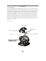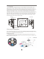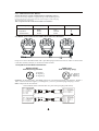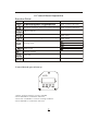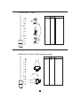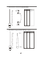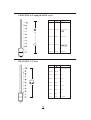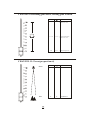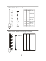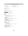
1
SPOT 250
USER MANUAL
www.yagang.com
1.Open the box and checking
Congratulations on choosing our products! Please carefully read this instruction manual in its
entirety and keep it well for using reference. This manual contained about the installation and the
relative using information of this products. Please according to this manual's relative speaking when
using this equipment.
This equipment was made of new style, high intensity plastic . It fully shows the modem times
light characteristic with beauty structure. And it was made according to CE standard. Fully up the
international standard of DMX512 agreement. Master or slave in phase control. Can be use in large
entertainment, theater, performing and playing hall, etc.
This product uses MSD 250 or MSD 250/2 electrical arc lamp. When receiving this product
please carefully bring and put; and check that whether this equipment has been damaged or not
during transportation. And please also check the following thing was enclosed:
Signal line ----------------------- one piece Safety string -----------------------one piece
User Manual-----------------------one set
Omega holder----------------------two pieces
2. Safety instructions
Every person involved with installation and maintenance of this device have to:
- be qualilfied
- follow the instructions of this manual
CAUTION:
¾
¾
¾
¾
¾
¾
K eep this device away from rain and moisture!
U nplug mains lead before opening the housing!
F OR YOUR OWN SAFETY, PLEASE READ THIS USER MANUAL CAREFULLY
B EFORE YOU INITIAL START - UP!
B e careful with your operations.
W ith a high voltage you can suffer a dangerous electric shock when touching the
wires!
¾ T his device has left our premises in absolutely perfect condition. In order to maintain
this condition and to ensure a safe operation, it is absolutely necessary for the user to
follow the safety instructions and warning notes written in this manual.
Important:
¾ The manufacturer will not accept liability for any resulting damages caused by the nonobservance of this manual or any unauthorized modification to the device.
¾ Please consider that damages caused by manual modifications to the device are not
subject to warranty.
¾ Never let the power-cord come into contact with other cables! Handle the power-cord
and all connections with the mains with particular caution!
¾ Make sure that the available voltage is not higher than stated on the rear panel.
¾ Always plug in the power plug least. Make sure that the power-switch is set to OFFposition before you connect the device to the mains. The power-plug has to be access
able after installing the device.
¾ Make sure that the power-cord is never crimped or damaged by sharp edges. Check the
device and the power cord from time to time.
¾ by the plug. Never pull out the plug by tugging the power-cord.
¾ This device falls under protection class I. Therefore it is essential to connect the
yellow/green conductor to earth.
¾ The electric connection, repairs and servicing must be carried out by a qualified
employee.
¾ Do not connect this device to a dimmer pack.
¾ Do not switch the fixture on and off in short intervals as this would reduce the lamp' s
life.
¾ During the initial start-up some smoke or smell may arise. This is a normal process and
does not necessarily mean that the device is defective.
¾ Do not touch the device's housing bare hands during its operation (housing becomes hot)!
¾ For replacement use lamps and fuses of same type and rating only.
CAUTION :
EYE DAMAGES !
Avoid looking directly into the light source(meant especially for epileptics) !
3. Operating determinations
¾ This device is a moving-head spot for creating decorative effects and was designed for
indoor use only.
¾ If the device has been exposed to drastic temperature fluctuation (e.g. After transportation), do not switch it on immediately. The arising condensation water might damage
your device. Leave the device switched off until it has reached room temperature.
¾ Never run the device without lamp!
¾ Do not shake the device. Avoid brute force when installing or operating the device.
¾ Never lift the fixture by holding it at the projector-head, as the mechanics may be
damaged. Always hold the fixture at the transport handles.
¾ When choosing the installation-spot, please make sure that the device is not exposed to
extreme heat, moistureor dust. There should not be any cables lying around. You
endanger your own and the safety of others!
¾ The minimum distance between light-output and the illuminated surface must be more
than 2 meters.
¾ Make sure that the area below the installation place is blocked when rigging, derigging
or servicing the fixture. Always fix the fixture with an appropriate safety-rope. Fix the
safety-rope at the correct holes only.
¾ Only operate the fixture after having checked that the housing is firmly closed and all
screws are tightly fastened.
¾ The lamp must never be ignited if the objective-lens or any housing-cover is open, as
discharge lamps may explose and emit a high ultraviolet radiation, which may cause
burns.
¾ The maximum ambient temperature ta = 45℃ must never be exceeded. Otherwise, the
lamp is switched off and the fixture is out of operation for 5 minutes..
4.Description of the device
1 - Moving head
2 - Yoke
3- Carry handles
4 - Base
Rear panel:
5 -Power switch
6 -DMX output
7 - DMX input
8- Power cord
9 - Fuse holder
LAM P:M SD 25 0/2
MSD 250
SERIAL DATA LI NK
1= GND
2= SIG.3= SIG.+
P OW ER S WI TCH
FUS E
LIGHTING CO NTRO L PROTOCOL:DMX51 2
S eria l n u m b er:
POW ER SUP PLY
T 3 .1 5A@2 30 V
T 6 .3 A@12 0V
Front panel:
10 - Mode-button
11 - Enter-button
12 - Up-button
13- Down-button
14 - Display
5.Installion
5.1 Fitting the lamp
To insert the lamp MSD 250 or MSD 250/2 open the top cover of the projector-head (see
the drawing to identify which cover is top) by loosening the 3 screws on the cover. Then
open the small lamp cover by loosening 2 fastening screws (see the drawing). If changing
the lamp, remove the old lamp from the socket. Insert the lamp to the socket. Do not
install a lamp with a higher wattage! A lamp like this generates temperatures the device is
not designed for. Damages caused by non-observance are not subject to warranty. Please
follow the lamp manufacturer‘s notes! Do not touch the glass bulb with bare hands
during the installation! Make sure that the lamp is installed tightly into the lampholder
system. Adjust the optimal distance 1-1.5 mm from the lens by turning the screw "A" (see
the drawings "Lamp adjustment" below) on the rear panel of the head. Then close the
small lamp cover by tighten 2 fastening screws again. Reclose the top cover of the head
and tighten the 3 screws.
Lamp assembly:
Fastening screws
Fastening screws
Top cover
Lamp
Lamp cover
5.2 Lamp adjust
The lamp holder is aligned at the factory. Due to differences between lamps , fine
adjustment may improve light performance. Strike the lamp, open the shutter and the iris,
set the dimmer intensity onto 100% and focus the light on a flat surface (wall). As the
optimum distance of the lamp from lens was adjusted during the installing or changing the
lamp (by turning the screw "A" ), it is necessary to adjust only the second position by
turning the screw "B" , in order to center the hot-spot (the brightest part of the beam). If
the hot spot seems to be too bright, you can lower its intensity by moving the lamp closer to
the reflector. Do so by turning the screw "A" until the light is evenly distributed. If the
light on the edge seems to be brighter as in the center, the lamp is too close at the reflector.
In this case, you need to move the lamp away from the reflector until the light is evenly
distributed and the beam appears bright enough.
Correct
Incorrect
Optimum distance
1-1,5mm
WARNING!
La mp is h ot! Ris k of fire ! P rote ct h and s a nd eye s.
Wait at l eas t 15 min . B efo re o pen ing the co vers
an d re mo vin g la mp from th e fi xture.
Minim um distan ce to li ght ed o bje ct:
Maximum ro om temperature t=45℃
Minimum distan ce f rom fla mmable mate rial d=0.5 m.
Ex terior surf ace tem pe ratu re T =8 0 ℃.
No t fo r do me stic us e.
Adjust lamp posit ion by t urning screws
and
Be su re t hat the lamp
bu lb n eve r to uch th e le ns
A
Screw“B”
B
Disco nne ct t he fixtu re from AC po we r
be fore re -lampin g.
Screw“A”
5.3Inserting/Exchanging gobos
Turn off the lamp and allow it to cool for at least 10 minutes. Disconnect the fixture from
power. To insert the gobos open the top cover of the moving-head by loosening the 3 screws
on the top cover and follow the instructions below:
Rotating gobo-wheel:
Press the ends of the fixation-ring together with an appropriate tool and remove it.
Remove the gobo and insert the new gobo. Press the ends of the fixation-ring together and
insert it in the front of the gobo.
5.4 Rigging the fixture
DANGER TO LIFE:Please consider the respective national norms during the
installation!The installation must only be carried out by an authorized dealer!
¾ The installation of the projector has to be built and constructed in a way that it can hold 10
times the weight for 1 hour without any harming deformation.
¾ The installation must always be secured with a secondary safety attachment, e.g. an
appropriate catch net. This secondary safety attachment must be constructed in a way that
no part of the installation can fall down if the main attachment fails.
¾ When rigging, derigging or servicing the fixture staying in the area below the installation
place, on bridges, under high working places and other endangered areas is forbidden.
¾ The operator has to make sure that safety-relating and machine-technical installations are
approved by an expert before taking into operation for the first time and after changes
before taking into operation another time.
¾ The operator has to make sure that safety-relating and machine-technical installations are
approved by an expert after every four year in the course of an acceptance test.
¾ The operator has to make sure that safety-relating and machine-technical installations are
approved by a skilled person once a year.
¾ The projector should be installed outside areas where persons may walk by or be seated.
¾ IMPORTANT! OVERHEAD RIGGING REQUIRES EXTENSIVE EXPERIENCE,
including (but not limited to)calculating working load limits, installation material being
used, and periodic safety inspection of all installationmaterial and the projector. If you
lack these qualifications, do not attempt the installation yourself, but instead use a
professional structural rigger. Improper installation can result in bodily injury and or
damage to property.
¾ The projector has to be installed out of the reach of people.
¾ If the projector shall be lowered from the ceiling or high joists, professional trussing
systems have to be used. The projector must never be fixed swinging freely in the room.
¾ Caution: Projectors may cause severe injuries when crashing down! If you have doubts
concerning the safety of a possible installation, do NOT install the projector!
¾ Before rigging make sure that the installation area can hold a minimum point load of 10
times the projector s weight.
¾ The projector can be placed directly on the stage floor or rigged in any orientation on a
truss without altering its operation characteristics.
¾ For overhead use, always install a safety-rope that can hold at least 10 times the weight of
the fixture. You must only use safety-ropes with screw-on carabines. Pull the safety-rope
through the two apertures on the bottom of the base and over the trussing system etc.
Insert the end in the carabine and tighten the fixation screw.
Omega holder
5.5 Connection to the mains
Verify the power supply settings before applying power!
If you wish to change the power supply settings,see the chapter Appendix.
Connect the fixture to the mains with the enclosed power cable and plug.
The earth has to be connected!
The occupation of the connection-cables is as follows:
Cable (EU)
Brown
Light blue
Y ellow/Green
Cable (US)
Black
White
Green
Pin
International
L
N
Live
Neutral
Earth
5.6 DMX-512 connection/connection between fixtures
Only use a stereo shielded cable and 3-pin XLR-plugs and connectors in order to connect the
controller with the fixture or one fixture with another.
Occupation of the XLR-connection:
DMX-OUTPUT
XLR mounting-socket:
1 - Ground
2 - Signal (-)
3 - Signal (+)
DMX-input
XLR mounting-plug:
1 1 - Ground
2 - Signal (-)
3 - Signal (+)
Caution: At the last fixture, the DMX-cable has to be terminated with a terminator. Solder a
120Ω resistor between Signal (-) and Signal (+) into a 3-pin XLR-plug and plug it in the
DMX-output of the last fixture.
The transform of the controller line of 3 pins and 5 pins (plug and socket)
5Pins canon(socket)
Pin 1: GND(SCREEN)
Pin 2: Signal(-)
Pin 3: Signal(+)
Pin 4: N/C
Pin 5: N/C
3Pins canon(plug)
Pin 1: GND(SCREEN)
Pin 2: Signal(-)
Pin 3: Signal(+)
3Pins canon(socket)
Pin 1: GND(SCREEN)
Pin 2: Signal(-)
Pin 3: Signal(+)
5Pins canon(plug)
Pin 1: GND(SCREEN)
Pin 2: Signal(-)
Pin 3: Signal(+)
Pin 4: N/C
Pin 5: N/C
6. Control Board Operation
Function Table:
Mode
Function
Condition
YES--negative direction
Vertical movement in positive or negative direction YES--negative direction
Address code set
Reset
YES--reset
Rainbow color wheel change color linear or stepping YES--linear
DMX512 mode
Automatic
Slave mode
Lamp on
Lamp off
Working mode
Lamp switch
Software version
Lamp hot
Lamp error
Control board operation way:
LED
1.Select working mode by pressing MODE.
2.Press ENTER to confirm the selection.
3.Press UP and DOWN to select working condition.
4.Press ENTER to confirm the selection.
7. DMX512 Channel Function
CHANNEL
FUNCTION
PAN
TILT
PAN FINE(proportional)
TILT FINE(proportional)
Speed of PAN/TILT movement
Lamp on/off & reset
Colors
Prism
Rotating gobos
R otating g obo index, rotating gobo rotation
Focus(proportional)
Shutter / strobe
Dimmer intensity(proportional)
CHANNEL 1: PAN
Value
Effect
255
100
0
0
Clockwise 53 0°
rotate
CHANNEL 2: TILT
Value
Effect
255
100
0
0
Anti-clockwise
280° rotate
CHANNEL 3: PAN FINE (proportio n al)
Value
Effect
255
100
0
0
Fine control of tilt
movement
CHANNEL 4: TILT FINE (proportional)
Value
Effect
255
100
0
0
Fine control of tilt
movement
CHANNEL 5: Speed of PAN/TILT movement
Value
Slow
Fast
Effect
255
100
0
0
Slow
fast
CHANNEL 6: Lamp on/off & reset
Value
Effect
240-255
95-100
No function
230-239
91-94
Lamp off after 3
140-229
55-90
No function
50-54
Lamp on after 3
0-127
0-49
No function
128-255
50-100
112-127
44-49
Pink
96-111
37-43
Blue
80-95
31-36
Orange
64-79
25-30
Green
48-63
19-24
Magenta
32-47
12-18
Yellow
16-31
6-11
Red
0-15
0-5
Open/white
128-139
CHANNEL 7: Color
Forwards rainbow
effect from slow to fast
CHANNEL 8: Prism
Value
Effect
Backwards rotation
from slow to fast
133-255
53-100
128-132
51-52
5-127
3-50
Forwards rotation
from fast to slow
0-4
0-2
No rotation
No rotation
CHANNEL 9: Rotating gobos
Value
Effect
224-255
88-100
Rotate gobo wheel
continue rotation
from slow to fast
160-223
63-87
Rotate gobo 5
128-159
50-62
Rotate gobo 4
96-127
37-49
Rotate gobo 3
64-95
25-36
Rotate gobo 2
32-63
12-24
Rotate gobo 1
0-31
0-11
Open/hole
CHANNEL 10:Rotating gobo index, rotating gobo rotation
Value
159-255
Effect
62-100
Backwards gobo rotation
from slow to fast
61-158
24-61
Forwards gobo rotation
from slow to fast
0-60
0-23
Gobo indexing (0-540°)
CHANNEL 11: Focus(proportional)
Near
Far
Value
Effect
255
100
0
0
close distance
far distance
CHANNEL 12:Shutter, strobe
Value
Effect
224-255
87-100 Shutter Open
192-223
75-86
Random strobeeffect from slow
to fast
160-191
62-74
Shutter Open
128-159
50-61
Pulse-effect in
sequences from
slow to fast
96-127
37-49
Shutter Open
64-95
25-36
Strobe-effect from
slow to fast (max
10flashes/s)
32-63
12-24
Shutter Open
0-31
0-11
Shutter closed
CHANNEL 13: Dimmer intensity(proportional)
Value
Brightest
Black
Effect
255
100
0
0
Brightest
Black
8. Technical specifications
US-model: Voltage............................AC100/110/120V , 50/60Hz
Fuse................................ T 6.3 A@120V
EU-model: Voltage............................AC 220/230/240V ,50/60Hz
Fuse ................................ T10 A @230V
Rated Power:500W
DMX512 Channel:13CHS
Luminous:18000 LUX
Lamp: Philips MSD250/2 or MSD 250 GY 9,5
Optical System: Linear electric focus
Color: 7dichroic-filters plus white
Strobe : Variable speed (1-10 flashes/sec)
Rigging:
-Stands directly on the floor
-Mounts horizontally or vertically with 2 clamps
-1 truss orientation
-Safety chain/cord attachment bolt
T emperatures
-Maximum ambient temperature ta: 45℃
-Maximum housing temperature tb (steady state): 80℃
Minimum distances:
-Min.distance from flammable surfaces: 0.5m
-Min.distance to lighted object: 2.0m
Dimmer: Smooth dimmer 0-100%
Pan / Tilt Movement:
-Pan 530°, Tilt 280°
-Micro-step scan effect
-Auto-repositioning by photoelectric repositioning system
-Linearity move speed adjust.
Dimensions and weight:
-Length of base (including handles): 400 mm
-Width of yoke: 400 mm
-Height (head horizontal): 476 mm
-Weight (net): 25 kg
Beampath:
9. Maintenance and cleaning
It is absolutely essential that the fixture is kept clean and that dust, dir t and smoke-fluid
residues must not buildup on or within the fixture. Otherwise, the fixtures light-output will
be significantly reduced. Regular cleaning willnot only ensure the maximum light-output,
but will also allow the fixture to function reliably throughout its life.A soft lint-free cloth
moistened with any good glass cleaning fluid is recommended, under no circumstances
should alcohol or solvents be used!
DANGER :Disconnect from the mains before starting anymaintenance work
The front objective lens will require weekly cleaning as smoke-fluid tends to building up
residues, reducing thelight-output very quickly. The cooling-fans should be cleaned
monthly.
The gobos may be cleaned with a soft brush. The interior of the fixture should be cleaned at
least annually using a vacuum-cleaner or an air-jet.
The dichroic colour-filters, the gobo-wheel and the internal lenses should be cleaned
monthly.
To ensure a proper function of the gobo-wheel , we recommend lubrication in six month
intervals. The quantity of oil must not be excessive in order to avoid that oil runs out when
the gobo-wheel rotates.
There are no ser viceable parts inside the device except for the lamp and the fuse.Please refer
to the instructions under "Fitting/Exchanging the lamp".Maintenance and service
operations are only to be carried out by authorized dealers.
Replacing the fuse
If the lamp burns out, the fine-wire fuse of the device might fuse, too. Only replace the fuse
by a fuse of same type and rating.Before replacing the fuse, unplug mains lead.
Procedure:
1) Unscrew the fuseholder on the rear panel of the base with a fitting screwdriver from the
housing (anti- clockwise).
2) Remove the old fuse from the fuseholder.
3) Install the new fuse in the fuseholder.
4) Replace the fuseholder in the housing and fix it.