1
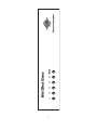
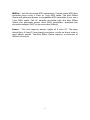
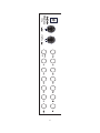
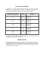
Mini Effect
Gizmo
User’s Manual
RJM Music Technology, Inc.
Mini Effect
Gizmo
User’s Manual
Version 1.3
September 26, 2013
RJM Music Technology, Inc.
2525 Pioneer Ave #1
Vista, CA 92081
E-mail: [email protected]
Web: www.rjmmusic.com
Copyright © 2011-2013 RJM Music Technology, Inc. All Rights
Reserved.
Amp Gizmo, Click Stopper, Effect Gizmo, Mini Amp Gizmo, Mini Effect
Gizmo, MasterMind, RG-16 and the RJM logo are trademarks of RJM
Music Technology, Inc.
Table of Contents
INTRODUCTION
1 FRONT PANEL
2 REAR PANEL
4 MIDI USAGE
7 Continuous Controllers
8 Bank Selection
8 Backing Up Your Settings: SysEx Dump
9 Factory Reset
9 10 SPECIAL FEATURES
Audio Buffer
10 Click Stopper
10 11 SETUP MODE
Selecting MIDI Channel and MIDI Options
11 MIDI Channels
11 Continuous Controller Ranges
12 GCX Compatibility Mode
12 Saving MIDI Channel and Options
12 EXAMPLE WIRING DIAGRAMS
13 TROUBLESHOOTING
16 SPECIFICATIONS
17 v
Introduction
Congratulations on purchasing the Mini Effect Gizmo audio loop
switcher! The Mini Effect Gizmo has been designed to provide our
acclaimed audio loop switching technology in a small package
suitable for pedalboards, rack drawers and other places where a full
sized switcher won’t fit.
The Mini Effect Gizmo provides five true bypass audio loops and a
professional quality audio buffer in a compact design. Because the
audio loops contain no active circuitry, the Mini Effect Gizmo can
work with any effects device regardless of signal level. Internal
voltage conversion is used to provide maximum headroom and
sound quality in the buffer and Click Stopper circuits. All of these
features work together to provide a pro-quality loop switcher in a
very small footprint.
1
Front Panel
Buttons 1 through 5 - These buttons turn audio loops 1 through 5
on and off. Each button lights up to indicate that the corresponding
audio loop is active.
Write – When held down for 3 seconds, this button saves the current
switch state to non-volatile memory. Buttons 1 through 5 will flash to
confirm that the state has been saved.
This function is not active until a Program Change message is
received at the MIDI In jack. See the MIDI Usage section for more
details.
The Write button is always lit up with a green LED to indicate that the
Mini Effect Gizmo is on.
2
3
1
2
3
4
5
Write
Mini Effect Gizmo
RJM Music Technology, Inc.
Rear Panel
Buf In – This is the Mini Effect Gizmo’s buffered input. Plugging into
this jack sends your guitar signal through the buffer and then on to
the audio loops. See the Special Features section for more
information on the audio buffer.
In – This is the passive input to the Mini Effect Gizmo. Plugging into
this jack sends the guitar signal straight to the audio loops, with no
active circuitry in between. Plugging in to the In jack overrides
anything plugged into the Buf In jack.
S / R 1 through 5 – These are the send and return jacks for each
audio loop. Connect your effect input to the S (send) jack and the
effect output to the R (return) jack. When a loop is active, the audio
signal from the previous loop is present at the send jack, and the
signal coming in to the return jack is passed on to the next loop.
When a loop is turned off, the audio signal bypasses the send and
return jacks and the send jack is grounded.
CS Out – This is the main output from the five loops. It uses the Click
Stopper circuit for click noise reduction. Please refer to the Special
Features section for more information on the Click Stopper.
Out – This is the passive output from the Mini Effect Gizmo. This jack
is directly connected to the output of loop 5, with no circuitry in
between. You can use both the Out and CS Out jacks simultaneously
if desired. For example, you can plug the CS Out jack into your amp
and the Out jack into a tuner.
MIDI Thru/Out – All incoming MIDI commands are passed back out
through this jack. The next MIDI device in your chain (if any) is
connected here. MIDI Thru/Out also doubles as a MIDI output when
transferring SysEx data over MIDI. (See the MIDI Usage section for
more details.) A standard 5-pin MIDI cable is typically used here, but
a 7-pin MIDI cable can be used to pass phantom power to a
connected MIDI device (if the connected device supports phantom
power).
4
MIDI In – Jack for incoming MIDI commands. Connect your MIDI foot
controller here using a 5-pin or 7-pin MIDI cable. The Mini Effect
Gizmo will phantom power a compatible MIDI controller if you use a
7-pin MIDI cable. The AC adapter provided with the Mini Effect
Gizmo can phantom power most MIDI controllers, provided the
controller accepts 9VDC at no more than 300mA.
Power – This unit requires power supply of 9 volts DC. The plug
should be a 5.5mm/2.1mm barrel connector, similar to those used in
most effects pedals. The Mini Effect Gizmo requires a minimum of
200mA of current.
5
6
MIDI Usage
The Mini Effect Gizmo can receive MIDI messages from any MIDI
controller. You can store different switch settings for MIDI program
numbers 1 through 128 in MIDI banks 0 and 1. When a Program
Change message is received on the correct channel, the Mini Effect
Gizmo will automatically recall the saved settings for the given
program number.
To set up for MIDI use, simply connect your MIDI controller to your
Mini Effect Gizmo’s MIDI In jack. The Mini Effect Gizmo is set for MIDI
Channel 1 by default. Either make sure your MIDI controller is set up
to transmit commands on Channel 1, or use the Mini Effect Gizmo’s
setup mode to change which MIDI channel the Mini Effect Gizmo
responds to. See the Setup Mode section for more details.
To save a program setting, perform the following steps:
1.
Using your MIDI controller, select a MIDI program number.
2.
Using the Mini Effect Gizmo buttons, select which audio
loops you wish to have turn on.
3.
Hold down the Write button on the Mini Effect Gizmo until
the LEDs flash. This should take about 3 seconds.
That’s all it takes. You can repeat this for any or all of MIDI program
numbers 1 though 128.
If the lights don’t flash after a few seconds of holding down the Write
button, it means that your Mini Effect Gizmo did not receive the MIDI
Program Change message. Check your MIDI cable connection, and
make sure that the MIDI controller and Mini Effect Gizmo are set to
the same MIDI channel.
Now that your settings have been saved, you can recall your settings
by using your MIDI controller to send a Program Change message
again. The Mini Effect Gizmo will call up your saved settings and turn
on the desired audio loops whenever it receives a MIDI Program
Change message.
7
Continuous Controllers
In addition to supporting MIDI Program Change messages, the Mini
Effect Gizmo supports MIDI Continuous Controller messages. The
following Continuous Controllers are supported by default:
Continuous Controller
Value
Function
CC88
0…63
64…127
Loop 1 off
Loop 1 on
CC89
0…63
64…127
Loop 2 off
Loop 2 on
CC90
0…63
64…127
Loop 3 off
Loop 3 on
CC91
0…63
64…127
Loop 4 off
Loop 4 on
CC92
0…63
64…127
Loop 5 off
Loop 5 on
*Setup Mode can be used to change which Continuous Controller
messages the Mini Effect Gizmo responds to. Please refer to the
Setup Mode section for more details.
Bank Selection
The Mini Effect Gizmo can store programs in MIDI banks 0 and 1, for a
total of 256 programs divided over two banks. Continuous Controller
#0 (Bank MSB) is used to select the current MIDI bank. Bank numbers
above bank 1 are ignored.
8
Backing Up Your Settings: SysEx Dump
A SysEx (System Exclusive) data dump will send the current Mini
Effect Gizmo system configuration out through the MIDI Thru/Out
port. You can then save this data to your computer, or copy the
settings directly to another Mini Effect Gizmo.
Hold down the Switch 5 button while powering up the Mini Effect
Gizmo, and the Mini Effect Gizmo will immediately send the SysEx
Dump. It only takes a couple of seconds to complete.
If you wish to copy settings from one Mini Effect Gizmo to another,
connect the MIDI Thru/Out of the transmitting unit to the MIDI Input
of the receiving unit, then power up the transmitting unit while
holding down the Switch 5 button. (Note that the receiving Mini
Effect Gizmo must be powered on and not in setup mode.) The
receiving unit will display a progress bar graph on the LEDs. The
transfer goes very quickly, taking only a couple of seconds. In the
case of an error, the receiving unit will flash all LEDs 5 times.
Once the transfer completes, the receiving unit will reset, then return
to normal operating mode. The receiving unit now has an exact copy
of the transmitting unit’s settings.
Factory Reset
To return the Mini Effect Gizmo to its factory state, hold the 1 and 4
buttons while you power it up. The lights should turn on briefly, then
turn off again. The Mini Effect Gizmo is now initialized and ready to
go.
9
Special Features
Audio Buffer
Using long cables or many effects may degrade the guitar signal,
causing it to lose clarity and definition. The audio buffer is used to
“strengthen” the guitar signal and preserve sound quality. The effect
may vary from subtle to significant, depending on the length and
quality of cables and type of effects used in your rig.
Plugging into the Buf In jack will put the buffer in the audio path,
and plugging into the In jack will bypass the buffer. When setting up
an effects rig, it’s best to try both of the inputs and use whichever
one you find sounds better.
Click Stopper
The Mini Effect Gizmo uses relays to perform its switching. Relays are
the cleanest, most transparent switching method available. The
disadvantage of relays is that they can produce a slight click in your
audio signal when they switch. This is more noticeable when using a
high gain amplifier or overdrive and distortion pedals. The Click
Stopper circuit found in the Mini Effect Gizmo is designed to greatly
reduce this click noise by muting the audio output briefly when the
relays switch.
Like the buffer, you can choose to use – or not use – the Click
Stopper. Using the CS Out jack enables the Click Stopper, and using
the Out jack bypasses the Click Stopper.
If you use both the In jack and the Out jack, the buffer and Click
Stopper are both bypassed, making the signal path completely
passive – the guitar signal only passes through relays.
10
Setup Mode
Selecting MIDI Channel and MIDI Options
Hold the Switch 1 button while powering the Mini Effect Gizmo on.
Keep holding the button until the LEDs flash. The Switch buttons will
now allow you to select the MIDI channel the Mini Effect Gizmo
responds to, as well as other MIDI-related options:
MIDI Channels
The Mini Effect Gizmo is set by default to send and receive on MIDI
Channel 1. To change the send/receive channel:
MIDI
Channel
1
2
3
4
5
6
7
8
9
10
11
12
13
14
15
16
Switch 1
LED
OFF
ON
OFF
ON
OFF
ON
OFF
ON
OFF
ON
OFF
ON
OFF
ON
OFF
ON
Switch 2
LED
OFF
OFF
ON
ON
OFF
OFF
ON
ON
OFF
OFF
ON
ON
OFF
OFF
ON
ON
Switch 3
LED
OFF
OFF
OFF
OFF
ON
ON
ON
ON
OFF
OFF
OFF
OFF
ON
ON
ON
ON
Switch 4
LED
OFF
OFF
OFF
OFF
OFF
OFF
OFF
OFF
ON
ON
ON
ON
ON
ON
ON
ON
You can also set a few other MIDI-related options using the other
Switch buttons:
11
Continuous Controller Ranges
The Switch 5 button controls the Continuous Controller range for all
switches:
CC Range
80…84
88…92 (default)
GCX
Number
1
2
Switch 5
LED
OFF
ON
GCX Compatibility Mode
To make the Mini Effect Gizmo work like a GCX by Voodoo Lab, turn
on all of Switches 1-4 in setup mode. This sets the MIDI channel to 16,
which is the channel used by the GCX. The GCX number (GCX#1 or
GCX#2) is set by Switch 5 (see above).
Enabling GCX mode allows the Mini Effect Gizmo to be easily
controlled by a Ground Control Pro (also by Voodoo Lab).
Saving MIDI Channel and Options
Once you’ve set the MIDI channel and options, press the Write
button. The Mini Effect Gizmo is now in normal operational mode.
12
Guitar
OUT
IN
OUT
IN
RJM Music Technology, Inc.
www.rjmmusic.com
OUT
IN
13
IN
OUT
IN
AC Adapter
To MIDI input of
next MIDI device
(if any)
MIDI Controller Out
Standard 5 pedal configuration
Pedals are wired in series and connected to the amp’s input
OUT
To Amplifier
Mini Effect Gizmo Wiring Diagram
Example Wiring Diagrams
14
Guitar
OUT
IN
OUT
IN
RJM Music Technology, Inc.
www.rjmmusic.com
OUT
IN
OUT
IN
Amp FX
Loop Return
AC Adapter
To MIDI input of
next MIDI device
(if any)
MIDI Controller Out
3 / 1 Split
The first three pedals are connected to the amp’s input
The last pedal is placed in the amp’s effects loop
Loop 4 (the split point) must be kept on at all times
Amp FX
Loop Send
To Amp
Input
Mini Effect Gizmo Wiring Diagram
15
Guitar
OUT
IN
OUT
IN
RJM Music Technology, Inc.
www.rjmmusic.com
OUT
IN
IN
OUT
IN
4
Mini
Line Out
Mixer
To Amp
2 pedals in series, 3 in parallel
Typically, the series pedals are overdrive, compression, etc.
and the parallel pedals are delay, chorus, reverb, etc.
This allows you to run multiple effects without muddying the
signal from placing too many effects in series.
This can be placed in front of an amp, or in an effects loop.
OUT
3
2
1
MIDI Controller Out
AC Adapter
To MIDI input of
next MIDI device
(if any)
Mini Effect Gizmo Wiring Diagram
Troubleshooting
Problem: The LEDs don’t flash when you hold down the Write
Button.
Solution: The Mini Effect Gizmo did not receive a MIDI Program
Change message. First, verify that you have a valid MIDI connection.
The MIDI output of your MIDI controller should be connected to the
MIDI input of the Mini Effect Gizmo by a MIDI cable that’s known to
be working correctly. The next most likely cause is that the Mini
Effect Gizmo is set to a different MIDI channel than your MIDI
controller. Check both devices to insure that they’re set to the same
channel. On the Mini Effect Gizmo, the MIDI channel is set to 1 by
default and can be changed in Setup Mode.
Problem: The signal coming out of the Mini Effect Gizmo is too loud.
Solution: There is a buffer level adjustment inside the Mini Effect
Gizmo. This is set to unity gain at the factory, but can be adjusted to
provide a boost. Remove the Mini Effect Gizmo lid (you need to
remove two screws on the top and two on each side). The level
adjustment is a small blue trimpot near the front panel input jack.
Using a Philips screwdriver, gently turn it all the way
counterclockwise for unity gain, or clockwise for a volume boost.
More troubleshooting tips can be found in the RJM Music Forum:
www.rjmmusic.com/forum
16
Specifications
Dimensions
Weight
Power
Phantom
Power
8.5 (W) x 1.6 (H) x 3.5 (D) inches
21.6 (W) x 4.1(H) x 8.9 (D) cm
21.7 ounces
615 grams
9 Volts DC @ 200mA
5.5mm OD, 2.1mm ID x 9.5mm barrel
connector
9VDC, 300mA maximum current when
using provided AC adaptor
Provided over pins 6 and 7 of the MIDI In
jack. Phantom power voltage is the same as
the power provided at the Power jack.
Phantom power is also passed through to
pins 6 and 7 of the MIDI Thru/Out jack.
Power coming out of this jack is limited to 1
Amp using a resettable fuse.
Memory
256 programs, arranged in 2 banks of 128
Memory is non-volatile and requires no
backup battery
17