1
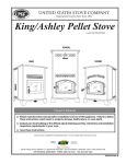
U USSC E STATES ST OV TED NI UNITED STATES STOVE COMPANY “Keeping North America Warm Since 1869” COMPANY King/Ashley Pellet Stove models 5500/5500M/5500XL 5500XL 5500M 5500 Owner’s Manual Please read this entire manual before installation and use of this appliance. Failure to follow these instructions could result in property damage, bodily injury, or even death. Contact your local building or fire officials about restrictions and installation inspection requirements in your area. Save these instructions. UNITED STATES STOVE COMPANY • 227 INDUSTRIAL PARK ROAD • SOUTH PITTSBURG, TENNESSEE 37380 • WWW.USSTOVE.COM FOR TECHNICAL ASSISTANCE: USSC PHONE: (800) 750-2723 FAX: (423) 837-2109 Part No.: 851641 E 1 Table of Contents TABLE OF CONTENTS............................................................................................... 2 Safety Precautions............................................................................................ 3 Specifications........................................................................................................ 4 Heating Specifications...................................................................................... 4 Dimensions....................................................................................................... 4 Electrical Specifications.................................................................................... 4 Fuel Considerations.......................................................................................... 4 Safety and EPA Compliance............................................................................. 4 Installation . ......................................................................................................... 5 Installation Options........................................................................................... 5 Floor Protection................................................................................................ 5 Clearances ...................................................................................................... 6 Venting Requirements...................................................................................... 7 Maximum Venting Distance.............................................................................. 7 Pellet Vent Type................................................................................................ 7 Pellet Vent Installation...................................................................................... 7 Pellet Vent Termination..................................................................................... 7 Vent Termination Clearances............................................................................ 8 Through the Wall Installation............................................................................ 9 Through the Roof/Ceiling Installation............................................................... 9 Outside Air Supply.......................................................................................... 10 Special Mobile Home Requirements.............................................................. 10 understanding your stove............................................................................ 11 control panel overview................................................................................. 12 Operation.........................................................................................................13-15 Unit Preparation.............................................................................................. 13 Performing Initial Test..................................................................................... 13 Performing a “Dry Run”................................................................................... 13 Start-Up Procedure......................................................................................... 14 Shut Down Procedure..................................................................................... 14 Daily Operation............................................................................................... 15 Safety and Convenience Features................................................................. 15 Maintenance....................................................................................................15-16 Exhaust System.............................................................................................. 15 Interior Chambers........................................................................................... 16 Ash Disposal................................................................................................... 16 Check and Clean the Hopper......................................................................... 16 Main Door Gaskets......................................................................................... 16 Blower Motors................................................................................................. 16 Painted Surfaces............................................................................................ 16 Glass............................................................................................................... 16 Fall Start-Up.................................................................................................... 16 Spring Shut Down........................................................................................... 16 Yearly Servicing.............................................................................................. 16 Trouble Shooting.............................................................................................. 17 ERROR CODES & DISPLAY INDICATORS.............................................................. 18 Repair Parts Diagram/LIST.........................................................................19-21 Wiring Diagram.................................................................................................... 22 2 USSC Safety Precautions IMPORTANT: Read this entire manual before installing and operating this product. Failure to do so may result in property damage, bodily injury, or even death. Proper installation of this stove is crucial for safe and efficient operation. Install vent at clearances specified by the vent manufacturer. Do not connect the pellet vent to a vent serving any other appliance or stove. Do not install a flue damper in the exhaust venting system of this unit. Use of outside air is not required for this unit. Contact your local building officials to obtain a permit and information on any additional installation restrictions or inspection requirements in your area. Do not throw this manual away. This manual has important operating and maintenance instructions that you will need at a later time. Always follow the instructions in this manual. Allow the stove to cool before performing any maintenance or cleaning. Ashes must be disposed in a metal container with a tight fitting lid. The closed container of ashes should be placed on a noncombustible surface or on the ground, well away from all combustible materials, pending final disposal. The exhaust system should be checked monthly during the burning season for any build-up of soot or creosote. Do not touch the hot surfaces of the stove. Educate all children on the dangers of a high-temperature stove. Young children should be supervised when they are in the same room as the stove. The hopper and stove top will be hot during operation; therefore, you should always use some type of hand protection when refueling your stove. A power surge protector is required. This unit must be plugged into a 110 - 120V, 60 Hz grounded electrical outlet. Do not use an adapter plug or sever the grounding plug. Do not route the electrical cord underneath, in front of, or over the heater. Do not route the cord in foot traffic areas or pinch the cord under furniture. This WKDWmeet or exceed the standard set by the Pellet)XHO Institute(PFI). The use of other fuels will voidZDUUDQW\ The heater will not operate during a power outage. If a power outage does occur, check the heater for smoke Never use gasoline, gasoline-type lantern fuel, spillage and open a window if any smoke spills into kerosene, charcoal lighter fluid, or similar liquids to the room. startor’freshenup’afireinthisstove.Keepallsuch The feed door must be closed and sealed during liquidswellawayfromthestovewhileitisinuse. operation. Aworkingsmokedetectormustbeinstalledinthesame Never block free airflow through the open vents of roomasthisproduct. the unit. Donotunplugthestoveifyoususpectamalfunction. TurntheON/OFFSWITCHto”OFF’andcontactyour Keep foreign objects out of the hopper. dealer. The moving parts of this stove are propelled by high torque electric motors. Keep all body parts away from Yourstoverequiresperiodicmaintenanceandcleaning the auger while the stove is plugged into an electrical (see”MAINTENANCE”).Failuretomaintainyourstove outlet. These moving parts may begin to move at any mayleadtoimproperand/orunsafeoperation. time while the stove is plugged in. Disconnect the power cord before performing any maintenance!NOTE:TurningtheON/OFFSwitchto Do not place clothing or other flammable items on or near this stove. ”OFF”doesnotdisconnectallpowertotheelectrical componentsofthestove. When installed in a mobile home, the stove must be grounded directly to the steel chassis and bolted Nevertrytorepairorreplaceanypartofthestoveunto the floor. WARNING—THIS UNIT MUST NOT lessinstructionsfordoingsoaregiveninthismanual. BE INSTALLED IN THE BEDROOM (per HUD Allotherworkshouldbedonebyatrainedtechnician. requirements). CAUTION—The structural Do not operate your stove with the viewing door integrity of the mobile home floor, wall, open. The auger will not feed pellets under these and ceiling/roof must be maintained. circumstancesandasafetyconcernmayarisefrom This appliance is not intended for commercial use. sparksorfumesenteringtheroom. * This appliance is a freestanding heater. It is not intended to be attached to any type of ducting. It is not a furnace. USSC 3 Specifications Heating Specifications Heat Output1 48,000 BTU/hr. Heating Capacity2 800 - 2,000 sq. ft. Fuel Burn Rate 2.0 - 6.0 lbs./hr. 3 Burn Time (lowest setting) 5500/5500M - 60 hrs. 5500XL - 160 hrs. Hopper Capacity 5500/5500M - 150 lbs. 5500XL - 320 lbs. BTU output will vary depending on the quality of fuel. Use PFI listed fuels for the best results. Heating capacity will vary depending on floor plan layout of your home, degree of insulation, and the outside temperature. 3 Pellet size may effect the actual rate of fuel feed and burn times. Fuel feed rates may vary by as much as 20%. Use PFI listed fuel for best results. 1 2 Dimensions Height 5500/5500M 5500XL 34 in. 47 1/4 in. 26 in. 26 in. Depth 25 in. 25 in. 250 lbs. 275 lbs. Width Weight Electrical Specifications Electrical Rating Watts (operational) 110-120 volts, 60 HZ, 3.0 Amps 175 (approx.) Watts (igniter running) 425 (approx.) FUEL CONSIDERATIONS Your King/Ashley stove is designed to burn premium hardwood pellets that comply with Association of Pellet Fuel Industries standards. (Minimum of 40 lbs density per cubic ft, 1/4” to 5/16” diameter, length no greater than 1.5”, not less than 8,200 BTU/lb, moisture under 8% by weight, ash under 1% by weight, and salt under 300 parts per million). Pellets that are soft, contain excessive amounts of loose sawdust, have been, or are wet, will result in reduced performance. SAFETY AND EPA COMPLIANCE Your King/Ashley stove has been safety tested and listed to ASTM E 1509, (UM) 84-HUD by OMNI-Test Laboratories, Inc. Portland, Oregon, USA. It is also certified and tested to EPA Phase II requirements. 4 USSC Installation Installation Options Read this entire manual before you install and use your King/Ashley stove. Failure to follow instructions may result in property damage, bodily injury, or even death! (See specific installation details for clearances and other installation requirements) A Freestanding Unit—supported by pedestal/legs and placed on a non-combustible floor surface in compliance with clearance requirements for a freestanding stove installation. An Alcove Unit—supported by pedestal/legs and placed on a non-combustible floor surface in compliance with clearance requirements for an alcove installation. Your King/Ashley stove may be installed to code in either a conventional or mobile home (see SPECIAL MOBILE HOME REQUIREMENTS). It is recommended that only a authorized technician install your King/Ashley stove, preferably an NFI certified specialist. IMPROPER INSTALLATION: The manufacturer will not be held responsible for damage caused by the malfunction of a stove due to improper venting or installation. Call (800) 750-2723 and/or consult a professional installer if you have any questions. Floor protection This unit must be installed on a non-combustible floor surface. If a floor pad is used, it should be UL listed or equal. The floor pad or non-combustible surface should be large enough to extend a minimum of 6-inches in front, 6-inches on each side, and 1-inch behind the stove (see FIGURE 1). Floor protection must extend under and 2-inches to each side of the chimney tee for an interior vertical installation (see FIGURE 2). Your King/Ashley stove will need a minimum 31” x 38” floor protector. A Floor Protector of 1 inch thick is recommended for this installation. USSC 5 Installation Clearances Your King/Ashley stove has been tested and listed for installation in residential, mobile home, and alcove applications in accordance with the clearances given in FIGURES 3-5 and TABLE 1. NOTE: Distance “C” on the left-hand side of your King/Ashley stove may need to be greater than the minimum required clearance for suitable access to the control panel. FIGURE 3 FIGURE 4 SIDEWALL CLEARANCES PARALLEL INSTALATION SIDEWALL CLEARANCES CORNER INSTALATION PARALLEL CORNER ALCOVE (5500(M) only) A - Backwall to unit B - Sidewall to flue C - Sidewall to top edge of unit D - Adjacent wall to unit E - Alcove depth F - Alcove height 2.00 / 50mm 13.00 / 330mm 8.00 / 203mm 8.00 / 203mm 36.00 - 914mm 60.00 - 1520mm TABLE 1 CLEARANCES ALCOVE INSTALLATION THIS INSTALLATION IS NOT APPLICABLE FOR MODEL 5500XL. FIGURE 5 ALCOVE CLEARANCES 6 USSC Installation Venting requirements Install vent at clearances specified by the vent manufacturer. Do not connect the pellet vent to a vent serving any other appliance or stove. Do not install a flue damper in the exhaust venting system of this unit. The following installation guidelines must be followed to ensure conformity with both the safety listing of this stove and to local building codes. IMPORTANT! This unit is equipped with a negative draft system that pulls air through the burn pot and pushes the exhaust out of the dwelling. If this unit is connected to a flue system other than the way explained in this manual, it will not function properly. Maximum venting distance Installation MUST include at least 3-feet of vertical pipe outside the home. This will create some natural draft to reduce the possibility of smoke or odor during appliance shutdown and keep exhaust from causing a nuisance or hazard by exposing people or shrubs to high temperatures. The maximum recommend vertical venting height is 12-feet for 3-inch type “PL” vent. Total length of horizontal vent must not exceed 4-feet. This could cause back pressure. Use no more than 180 degrees of elbows (two 90-degree elbows, or two 45-degree and one 90-degree elbow, etc.) to maintain adequate draft. Pellet vent type A UL listed 3-inch or 4-inch type “PL” pellet vent exhaust system must be used for installation and attached to the pipe connector provided on the back of the stove (use a 3-inch to 4-inch adapter for 4-inch pipe). Connection at back of stove must be sealed using Hi-Temp RTV. Use 4-inch vent if the vent height is over 12-feet or if the installation is over 2,500 feet above sea level. We recommend the use of Simpson Dura-Vent® or Metal-Fab® pipe (if you use other pipe, consult your local building codes and/or building inspectors). Do not use Type-B Gas Vent pipe or galvanized pipe with this unit. The pellet vent pipe is designed to disassemble for cleaning and should be checked several times during the burning season. Pellet vent pipe is not furnished with the unit and must be purchased separately. Pellet vent installation The installation must include a clean-out tee to enable collection of fly ash and to permit periodic cleaning of the exhaust system. 90-degree elbows accumulate fly ash and soot thereby reducing exhaust flow and performance of the stove. Each elbow or tee reduces draft potential by 30% to 50%. All joints in the vent system must be fastened by at least 3 screws, and all joints must be sealed with Hi-Temp RTV silicone sealant to be airtight. The area where the vent pipe penetrates to the exterior of the home must be sealed with silicone or other means to maintain the vapor barrier between the exterior and the interior of the home. Vent surfaces can get hot enough to cause burns if touched by children. Noncombustible shielding or guards may be required. Pellet vent termination Do not terminate the vent in an enclosed or semi-enclosed area, such as; carport, garage, attic, crawl space, under a sundeck or porch, narrow walkway, or any other location that can build up a concentration of fumes. The termination must exhaust above the outside air inlet elevation. The termination must not be located where it will become plugged by snow or other materials. Do not terminate the venting into an existing chimney. USSC 7 Installation Vent termination clearances: A) Minimum 4-foot clearance below or beside any door or window that opens. B) Minimum 1-foot clearance above any door or window that opens. C) Minimum 3-foot clearance from any adjacent building. D) Minimum 7-foot clearance from any grade when adjacent to public walkways. E) Minimum 2-foot clearance above any grass, plants, or other combustible materials. F) Minimum 3-foot clearance from an forced air intake of any appliance. G) Minimum 2-foot clearance below eves or overhang. H) Minimum 1-foot clearance horizontally from combustible wall. I) Must be a minimum of 36-inches above the roof and 24-inches above the highest point or the roof within 10-feet. G 8 USSC Installation THROUGH THE WALL INSTALLATION (Recommended installation) To vent the unit through the wall, connect the pipe adapter to the exhaust motor adapter. If the exhaust adapter is at least 18-inches above ground level, a straight section of pellet vent pipe can be used through the wall. Your King/Ashley dealer should be able to provide you with a kit that will handle most of this installation, which will include a wall thimble that will allow the proper clearance through a combustible wall. Once outside the structure, a 3-inch clearance should be maintained from the outside wall and a clean out tee should be placed on the pipe with a 90-degree turn away from the house. At this point, a 3-foot (minimum) section of pipe should be added with a horizontal cap, which would complete the installation (see FIGURE 7). A support bracket should be placed just below the termination cap or one every 4-feet to make the system more stable. If you live in an area that has heavy snowfall, it is recommended that the installation be taller than 3-feet to get above the snowdrift line. This same installation can be used if your stove is below ground level by simply adding the clean-out section and vertical pipe inside until ground level is reached. With this installation you have to be aware of the snowdrift line, dead grass, and leaves. We recommend a 3-foot minimum vertical rise on the inside or outside of the house. FIGURE 7 TYPICAL THROUGH THE WALL INSTALLATION The “through the wall” installation is the least expensive and simplest installation. Never terminate the end vent under a deck, in an alcove, under a window, or between two windows. We recommend Simpson Dura-Vent® or Metal-Fab® kits. Through the roof/Ceiling Installation When venting the stove through the ceiling, the pipe is connected the same as through the wall, except the clean-out tee is always on the inside of the house, and a 3-inch adapter is added before the clean-out tee. You must use the proper ceiling support flanges and roof flashing (supplied by the pipe manufacturer; follow the pipe manufacturer’s directions). It is important to note that if your vertical run of pipe is more than 15-feet, the pellet vent pipe size should be increased to 4-inches in diameter. Do not exceed more than 4-feet of pipe on a horizontal run and use as few elbows as possible. If an offset is required, it is better to install 45-degree elbows rather than 90-degree elbows. USSC 9 Installation Outside Air Supply (optional) Depending on your location and home construction, outside air may be necessary for optimal performance. Metal pipe (solid or flexible) must be used for the outside air installation. PVC pipe is NOT approved and should NEVER be used. A wind shield over the termination of the outside air pipe or a 90-degree elbow or bend away from the prevailing winds MUST be used when an outside air pipe is installed through the side of a building. The outside air termination MUST be at least 1-foot away from the exhaust system termination. The outside air pipe on your King/Ashley stove is 1 7/8” OD. The outside air connecting pipe must be at least 1 7/8” ID. The outside air connection used MUST NOT restrict the amount of air available to your stove. The outside air connecting pipe must be as short and free of bends as possible, and it must fit over, not inside, the outside air connection to the stove. FIGURE 9 TYPICAL FRESH AIR TERMINATION FIGURE 8 EXHAUST/INLET LOCATIONS NOTE: Dimensions from the floor to your stoves inlet/exhaust pipes are approximate and may vary depending on your installation. Special Mobile Home Requirements WARNING! - Do not install in a sleeping room CAUTION! - The structural integrity of the mobile home floor, wall, and ceiling/roof must be maintained. In addition to the previously detailed installation requirements, mobile home installations must meet the following requirements: • The stove must be permanently attached to the floor. • The stove must be electrically grounded to the steel chassis of the mobile home with 8 GA copper wire using a serrated or star washer to penetrate paint or protective coating to ensure grounding. • Vent must be 3 or 4-inch “PL” Vent and must extend a minimum or 36-inches above the roofline of the mobile home and must be installed using a UL/ULC listed ceiling fire stop and rain cap. • When moving your mobile home, all exterior venting must be removed while the mobile home is being relocated. After relocation, all venting must be reinstalled and securely fastened. • Outside Air is mandatory for mobile home installation. See your dealer for purchasing. • Check with your local building officials as other codes may apply. 10 USSC Understanding your stove How your stove works Your King/Ashley stove utilizes a inclined auger fuel feed system that is operated by a microprocessor controlled digital circuit board. The digital circuit board allows the inclined auger fuel feed system to run in a timer-based, non-continuous cycle; this cycling allows the auger to run for a predetermined period of seconds. The auger pushes pellets up a chute located at the front/bottom of the hopper which in turn falls through another chute into the burnpot. Your stove is equipped with an automatic ignition system that should ignite the fuel within 5-10 minutes from pressing the ON button. As pellets enter the burn pot and ignite, outside air is drawn across the fuel and heated during the combustion process which is then pulled through the heat exchanger by the exhaust motor or draft fan. As the stove heats up, room air is circulated around the heat exchanger by means of a room air blower, distributing warm air into the room. The amount of heat produced by the stove is proportional to the rate of the fuel that is burned, and this rate is controlled by the “HEAT RANGE” setting. In order to maintain combustion of the fuel at a desired rate, the air provided to the burn chamber by the exhaust or draft fan must be maintain precisely. Too little air will result in a flame that is non-energetic or lazy. If the fuel continues to flow with too little air for long enough, the burn pot will fill with too much fuel and the fire will smother out. To much air will result in a flame that is overactive or aggressive. The flame in this situation is typically very blue at the bottom and resembles a blow torch. If this situation continues, the fuel in the burn pot will be consumed and the fire will go out. Matching the amount of air required for proper combustion to the fuel rate is the primary objective in effectively burning pellets of various brands and qualities in your stove. The air to fuel ratio can be adjusted to allow almost any fuel quality to burn effectively by following the procedures detailed in the remainder of this manual. Because a forced draft pressure is required for the combustion process inside your stove, it is extremely important that the exhaust system be properly installed and maintained. And, that when operating your stove, you make sure that the viewing door is properly sealed. 4 Digit Display FIGURE 10 DIGITAL CONTROL PANEL Up / Down Buttons : Heat Range Room Fan Draft Fan On Indicator & Button USSC Auto Mode Indicator Off Indicator & Button Auger Delay Indicator & Button 11 Control Panel Overview Turning the heater ON/OFF, as well as adjustments for the fuel feed rate and room fan speed are performed by pressing the appropriate button(s) on the control panel which is located on the lower left-hand side of your heater. This unit can be changed between an automatic operation or a manual operation. The controller comes default in the automatic mode. • ON/OFF Pressing the “ON” button on the control panel will begin the start-up sequence for the heater. Fuel will begin to feed through the auger feed system after 3 minutes. Pressing and holding the “ON” button will rotate the auger continuously until button is released, which feeds additional fuel. Pressing the “OFF” button on the control panel will cause the heater to enter its shut-down sequence. The fuel feed system will stop pulling fuel from the hopper and, once the fire goes out and the heater cools down, the fans will stop running. • HEAT RANGE Pressing the “Heat Range” arrows, up or down, will adjust the amount of fuel being delivered to the burnpot. • DRAFT FAN The draft fan (exhaust) will come on as soon as the “ON” button is pressed. The fan will automatically adjust its speed in accordance to the heat range setting. However, this speed can be manually operated by pressing the “Draft Fan” arrows up or down. “Draft Fan” when pressed, the display will show “Df-A”, which is automatic. Press the arrows again to adjust fan speed. When the heater is in the manual mode, the optional thermostat will not properly control the unit. When adjusting the Draft Fan setting, try only 1 setting above or below the heat setting. It is better to leave the stove in the automatic mode. • ROOM FAN The room fan will come on once the unit has reached operating temperature. By pressing the “Room Fan” buttons, the display will show “Rf-A” which is automatic or “Rf-1” through “Rf-9” for manual settings. In auto mode, the room fan’s speed will automatically be adjusted in accordance with the heat range setting. By pressing the “Room Fan” up arrow, you can adjust the fan speed setting up to “Rf-9”. The room fan must operate at a level greater than or equal to the heat range setting. • AUX - USED TO RETURN THE STOVE TO THE FACTORY SETTINGS To return the stove to it’s original factory settings, press and hold the AUX UP and AUX DOWN buttons simultaneously for 3 seconds. • AUGER DELAY The “Auger Delay” button can be used to pause rotation of the Auger for approx. 1 minute. This can be cancelled by pressing the “ON” button. The “Auger Delay” is normally used only during the start up cycle to slow the fuel delivery down during the initial ignition. • MODE The “Mode” button is used to switch between manual and automatic mode. When in auto mode, the fans and auger will operate at preset intervals unless changed manually using the buttons mentioned above. When in manual mode, the draft fan (exhaust) will operate at full speed (100%). During normal operation, the unit is constantly monitored for problems. In the event of an error condition, the unit will stop and an error will be displayed. See the list of error codes found at the end of this manual. 12 USSC Operation UNIT PREPARATION After carefully unpacking and reading the instructions for installing your stove, you will need to perform the following steps: • Attach the included spring handle to the door handle by screwing it on in a respective location. • Attach the electrical cord to the back of the stove first; then plug it into a 110-volt outlet (an outlet surge protector is highly recommended). PERFROMING AN INTIAL TEST This test is used at the factory where the stoves are assembled to test the functionality of the control and the stove before the unit is shipped. To perform this test, press and hold the OFF and AUGER DELAY buttons simultaneously for 3 seconds. To advance through the test, press any key unless otherwise noted in the test step. 1.) Exhaust Fan Output Test – The display will show “drft”. The exhaust fan is turned on full then reduced to a level just above the typical minimum pressure switch setting. The ON LED indicates whether the pressure sensor is detected. If the pressure switch is not detected, the fan ramps to full on for two seconds then returns to the previously established level if the pressure switch closes. If the Draft Fan Fuse is not blown and the fuse detection circuit is functioning, the Draft Fan LED will be lit and the other three top row LEDs will be off. 2.) Room Fan Output Test - The display will show “rfan”. The room fan is turned on full. If the Room Fan Fuse is not blown and the fuse detection circuit is functioning, the Room Fan LED will be lit and the other three top row LEDs will be off. 3.) Ignitor Output Test - The display will show “ignt”. The ignitor motor is turned on full. If the Ignitor (AUX) Fuse is not blown and the fuse detection circuit is functioning, the Aux LED will be lit and the other three top row LEDs will be off. 4.) Auger Output Test - The display will show “augr”. The auger motor is turned on full. If the Auger Fuse is not blown and the fuse detection circuit is functioning, the Heat Range LED will be lit and the other three top row LEDs will be off. 5.) Hopper Switch Test – The display will show “hppr”. The “ON” LED is lit. If the hopper switch is open (lid is open), the “HEAT RANGE” LED will turn on. If the lid is closed, the “HEAT RANGE” LED will be off. 6.) Thermostat Input Test – The display will show “stat”. If the thermostat input is closed, the ON LED will turn on, otherwise it will be off. 7.) Flue gas Thermistor Test – The display will show the fluegas temperature in degrees F. 8.) AC Frequency Test - Displays the measured AC Frequency in hertz followed by the letter ‘H’. 9.) Watchdog Reset – The watchdog timer is tested to ensure that the board can be reset. The message “BYE” is displayed until the watchdog resets the board. Performing a “dry run” Perform a “dry run” on your stove prior to making the exhaust/inlet connections and starting your stove for the first time. 1.) Check that there is no fuel or ANY foreign material in the hopper or burn-pot. 2.) Check that the viewing door and hopper lid is securely closed. 3.) Press the “ON” button on the control panel. Verify that the ON LED is lit (blinking) and the display shows HR-1. Also the LED above the HEAT RANGE and the AUTO MODE indicator should be lit. If any other LED’s are lit or flashing, consult the “Display Indicators” in this manual. 4.) You should hear the exhaust (draft) fan running immediately and the auger should begin turning continuously for 1 minute. 5.) The auto fuel ignitor (located inside the backwall of the burnpot) should begin to glow red/orange after 3 minutes. 6.) The Room Fan will not operate at this time since the unit must reach a factory preset temperature. Do not open the viewing door, the auto-start igniter will get very hot during this test. The stove will automatically shut down after approximately 23 minutes. USSC 13 Operation START-UP PROCEDURE Never use gasoline, gasoline-type lantern fuel, kerosene, charcoal lighter fluid, or similar liquids to start or “freshen up” a fire in this stove. Keep all such liquids well away from the stove while it is in use. 1.) Verify that the hopper is clean and free of foreign matter. 2.) Verify that all of the required exhaust/inlet connections have been made in accordance with this manual and that the stove is plugged into an outlet (an outlet surge protector is highly recommended). 3.) Fill the hopper with wood pellets; do not allow any part of the bag or any other foreign material into the hopper, as this may jam the auger. 4.) Ensure that all pellet matter is cleared from the hopper seating surface. 5.) Close the hopper lid. The unit WILL NOT feed fuel with the hopper lid open. 6.) Make sure that the viewing door is securely closed (the safety pressure switch will not allow the stove to feed fuel if there is no draft pressure inside the stove) . 7.) Press the “ON” button on the control pad and set the “heat Setting” to your desired setting. 8.) The stove will begin to feed fuel and the auto-start igniter will ignite the fuel in approximately 5 minutes. Once a consistent flame has been established, you can adjust the “Heat Range” and “Blower Speed” on the control pad to your desired settings. (Note: The distribution blower will not function until the heat exchanger in the stove reaches the factory preset temperature). First Fire: Adjust the “Heat Range” and “Blower Speed” to a “3” setting and allow the stove to operate in this manner for approximately three (3) hours (or more if necessary), allowing the stove to “cure out” as the paint and oils from the manufacturing process burn off. We recommend that you open doors and windows in your home during this process. Adjust setting to desired setting. SHUT DOWN PROCEDURE WARNING: Never shut down this unit by unplugging it from the power source. Press the “OFF” button on the control pad to put the stove in shut down mode. At this time, the red light above the pad will illuminate. Once this is done, the auger will stop feeding pellets, but the distribution blower and exhaust blower will continue to operate. When the internal temperature of the unit drops below the factory preset temperature, the distribution blower and exhaust blower will cease to operate. The red light will then shut off and the unit will be completely shut down. The hotter the unit is during its operation, the longer it will take for the stove to complete the shut down cycle. If the stove stays on for more than 2 hours after pressing the “OFF” button and you are sure that the fire is out, the stove can be unplugged from the outlet. After approximately 10 seconds, the unit can be re-connected to the power source and the control board will be reset. 14 USSC Operation DAILY OPERATION The hopper and stove top will be hot during operation; therefore, you should always use some type of hand protection when refueling your stove. Never place your hand near the auger while the stove is in operation. This unit should be filled when the hopper level drops below 3-inches. In the event of a power outage, the stove will not function. It is very important that unit be vented properly (with outside air), as the natural draft is needed to clear the smoke from the stove during a power outage. If the unit was “ON” when the power outage occurred, one of the following will take place: 1.) If the stove is still warm, it will resume feeding fuel and continue to operate normally. If the fire has gone out, you will have to press the “OFF” button and then the “ON” button again to begin a new start-up sequence. 2.) If the stove has cooled-off, it will reset to its “OFF” condition. At this point, you may press the “ON” button and the unit will begin a new start-up sequence. NOTE: The unit will also shut down in the event of an exhaust blower failure; if this is the case, the unit will not re-start and you must contact Customer Service at (800) 750-2723. safety and Convenience features Your King/Ashley incorporates a safety pressure switch that helps ensure that everything is in proper working order before feeding fuel to the burn pot. Because the stove works using an induced draft pressure, the stove will not continue to operate if the viewing door is left open; or if the exhaust blower fails or the exhaust system is blocked. The temperature limit control will prevent your stove from operating at abnormally high temperatures. Should the stove temperature begin to approach the factory pre-set limit, the temperature limit control will automatically slow down the auger feed rate until the temperature returns to a normal condition. Even though the heater will operate on setting “5” (HI), we recommend to operate your heater on this setting for only a short period of time. (1 hour etc.) Your King/Ashley stove also includes an auto-start igniter as a standard feature. The use of other fire starter materials (wood chips, starter gel, etc.) is not necessary. By simply pressing the “ON” button on the digital control panel, your stove will begin to feed fuel and automatically start within 5 minutes. Maintenance Failure to clean and maintain this unit as indicated can result in poor performance and safety hazards. Unplug your stove’s electrical cord prior to removing the back panel or opening the exhaust system for any inspection, cleaning, or maintenance work. Never perform any inspections, cleaning, or maintenance on a hot stove. Do not operate stove with broken glass , leakage of flue gas may result. Exhaust System The by products of combustion contain small particles of fly ash. Fly ash will collect in the exhaust venting system and restrict the flow of flue gases. Incomplete combustion, such as during startup, shutdown, or incorrect operation of the stove will lead to soot formation which will collect in the exhaust system. Therefore, it is important that the exhaust system be inspected and cleaned at least monthly during the burning season. Check the clean out tees periodically to determine the required cleaning schedule. 3 or 4-inch chimney brushes are available for chimney cleaning. If the exhaust system or outside air pipes have screens on them, frequently clean the screen. A plugged screen will shut off combustion air and cause a fire to die or burn poorly. USSC 15 Maintenance Interior Chambers Periodically remove and clean the burnpot and the area inside the burnpot housing. In particular it is advisable to clean out the holes in the burnpot to remove any build up that may prevent air from moving through the burn pot freely. Remove the two(2) plates on each side of the burnpot housing and clean out that rear chamber. If a vacuum is used to clean your stove, we suggest using a vacuum designed for ash removal. Some regular vacuum cleaner (i.e. shop vacs) may leak ash into the room. Ash Disposal Ashes should be placed in a metal container with a tight fitting lid. The closed container of ashes should be placed on a noncombustible floor or on the ground, well away from all combustible materials, pending final disposal. If the ashes are disposed of by burial in soil or otherwise locally dispersed, they should be retained in the closed container until all cinders have been thoroughly cooled. Check and Clean the Hopper Check the hopper periodically to determine if there is any sawdust or pellets that are sticking to the hopper surface. Clean as needed. Door and glass Gaskets Inspect the main door and glass window gaskets periodically. The main door may need to be removed to have frayed, broken, or compacted gaskets replaced by your Authorized “King/Ashley” Dealer. The glass gasket has a gap at the bottom for the airwash. Blower Motors Clean the air holes on the motors of both the exhaust and distribution blowers annually. Remove the exhaust blower from the exhaust duct and clean out the internal fan blades as part of your fall start-up. Painted Surfaces Painted surfaces may be wiped down with a damp cloth. If scratches appear, or you wish to renew your paint, contact your Authorized “King/Ashley” Dealer to obtain a can of suitable high-temperature paint. GLASS We recommend using a high quality glass cleaner. Should a build up of creosote or carbon accumulate, you may wish to use 000 steel wool and water to clean the glass. In the event you need to replace the glass, only high temperature ceramic glass of the correct size and thickness may be used. Contact your Authorized “King/Ashley” Dealer to obtain this glass. FALL START UP Prior to starting the first fire of the heating season, check the outside area around the exhaust and air intake systems for obstructions. Clean and remove any fly ash from the exhaust venting system. Clean any screens on the exhaust system and on the outside air intake pipe. Turn all of the controls on and make sure that they are working properly. This is also a good time to give the entire stove a good cleaning throughout. SPRING SHUTDOWN After the last burn in the spring, remove any remaining pellets from the hopper and the auger feed system. Scoop out the pellets and then run the auger until the hopper is empty and pellets stop flowing (this can be done by pressing the “ON” button with the viewing door open). Vacuum out the hopper. Thoroughly clean the burnpot, and firebox. It may be desirable to spray the inside of the cleaned hopper with an aerosol silicone spray if your stove is in a high humidity area. The exhaust system should be thoroughly cleaned. YEARLY SERVICING A yearly servicing and cleaning by your Authorized “King/Ashley” Dealer is recommended. A fee may be charged for this service. 16 USSC Trouble Shooting Disconnect the power cord before performing any maintenance! NOTE: Turning the ON/OFF Switch to ”OFF” does not disconnect all power to the electrical components of the stove. Never try to repair or replace any part of the stove unless instructions for doing so are given in this manual. All other work should be done by a trained technician. PROBLEM CAUSE: To rich air/fuel mixture Orange, lazy flame_excessive fuel build-up in the burnpot • Clean out the burnpot and burnpot housing • Make sure that the viewing door is closed and sealed properly. If not, adjust door catch and/or replace door gaskets. • Check that all outside connections are clear of any obstructions. • Check the exhaust system; clean as needed. PROBLEM CAUSE: Burnpot burns out of fuel Fire goes out or stove shuts down. • Hopper is empty, refill the hopper. • Loss of draft pressure. Make sure that the viewing door is closed and sealed properly. If not, adjust door catch and/or replace door gaskets. Check that all outside connections are clear of any obstructions. Check the exhaust system; clean as needed. • Check that the pressure switch connection to the firebox is free of ash or clear of obstructions. • Auger system is jammed or there is a “bridging” of the fuel in the hopper, preventing fuel from flowing into the auger feed system. PROBLEM CAUSE: Auto-Start Igniter fails to ignite the fuel in the burn pot. Stove does not start a fire when the “ON” button is pushed • Turn the stove “OFF”. Clear the unburnt fuel from the burnpot and try again. • Check the pellet quality. Replace if moist, wet, or dirty. • Loss of draft pressure. Make sure that the viewing door is closed and sealed properly. If not, adjust door catch and/or replace door gaskets. Check that all outside connections are clear of any obstructions. Check the exhaust system; clean as needed. • Check that the auto-start igniter is not blocked with ash or soot. (The igniter is located behind the burnpot on the back wall of the firebox.) • Check that the pressure switch connection to the firebox is free of ash or clear of obstructions. • The auto-start igniter gets “red hot” during start-up. If you can not visibly see the igniter glowing during start-up, then the igniter may need to be replaced or there is a problem with the electrical control system. USSC 17 Error Codes and Display Indicators Error Code Error Descrption Possible Causes Err1 The high limit temperature sensor has tripped. • • • • Inadequate ventilation. Room fan failure. Exhaust Blockage. Electrical Open in the over temperature switch or wiring. Err2 Stove ran out of fuel during normal operation. • • • • Hopper Empty. Auger output failure or jam. Flame of fuel quality caused fire to burn too slowly or go out. Electrical Open in low temperature switch or wiring. Err3 The stove was unable to reach the Room Fan On temperature within the startup time. • Flame or Fuel quality caused the fire to burn too slowly or go out. • Auger output failure or jam Hopper empty on startup. Err4 The power failed while the stove was • Electrical Open in low temperature switch or wiring. hot, and when power was restored, • Power loss the fire was out. Err5 The Auger output fuse has blown. • Auger motor jammed or bad. Err6 The Ignitor output fuse has blown. • Ignitor shorted out or bad. Err7 The Draft Fan (Exhaust Fan) output fuse has blown. • Draft Fan motor jammed or bad. Err8 The Room Fan output fuse has blown. • Room fan motor jammed or bad. Display Indicators Several situations or events are indicated in normal operation by blinking display indicators or segments in the display: Flashing On Indicator: This means that the stove is in the “Start Up” state waiting for either a 3 minute timeout to begin burning or for the stove to reach the warm temperature whichever comes first. Flashing Off Indicator: This indicates that the stove is in the “Shutdown” state waiting for the OFF button, or for a 15 minute period after the stove was turned off, or for the stove to cool down, or for the door to be closed. Flashing dash in Heat Range Display: This indicates that the stove is in the normal run mode and is ramping from the current heat range setting to the target heat range setting. Once the ramp is complete, the dash will stop flashing. For ramping from heat range 1 to 5, the default time is 12 minutes (with a 90 second ramp time). Flashing Automatic Mode Indicator: This indicates that the stove is in normal operation and is running in the automatic mode. However, either the Draft Fan or Auxiliary setting is manually configured. Flashing Draft Fan Setting Indicator: This indicates that the stove is in normal operation and that the vacuum sensor detects a loss of pressure either because the door is open or because there is a negative pressure in the room with respect to the exhaust. Flashing Aux Indicator: This indicates that the ignitor is on during the lighting stage. Quickly (changes twice per second) Flashing Heat Range Setting Indicator: This indicates that the stove is in normal operation and that an overtemperature condition exists causing the fuel to stop. Slowly (changes once per second) Flashing Heat Range Setting Indicator: This indicates that the stove is in a cut back condition in an attempt to prevent an overtemperature shutdown. Factory Defaults To return the control to its original factory default settings, press and hold the AUX UP and AUX DOWN buttons together for three seconds. 18 USSC Parts Diagram/List models 5500, 5500M & 5500XL Model 5500 7 3 8 4 6 12 1 9 12 9 10 9 10 10 11 5 13 2 Item Part No. Title PARTS LIST Qty. Item Part No. Title 1 2 3 4 5 6 7 1 1 1 1 1 1 4.3 ft 25490 891166 891188 891186 25517 891168 88082 Door Weldment Ceramic Glass Glass Retainer, Top Glass Retainer, Bottom Handle, Door Latch, Door 3/4” Rope Gasket 8 9 10 11 12 13 88087 83297 83547 83903 83546 891167 Model 5500M/5500XL 3.75 ft 3 3 1 2 1 10 8 9 Qty. Glass Gasket 8-32 Hex Nut Washer Spring 5/16 x 18 Hex Jamb Nut Spring Handle 5 1 2 11 3 12 7 6 4 Item Part No. Title PARTS LIST Qty. Item Part No. Title 1 2 3 4 5 6 7 8 1 1 1 1 4.5 ft 3.5 ft 1 1 USSC 25507 25492 83506 891067 88066 88087 25520 25521 Feed Door Handle, Door 3/8 x 1 1/4 Roll Pin Door Glass w/ Ashley Logo 5/8” Rope Gasket Glass Gasket (1 x 1 3/16) Bottom Glass Retainer Top Glass Retainer 9 83278 10 83202 11 89574 12 25393 N/S 25080MB N/S 83508 N/S 83338 N/S - Not Shown Washer Machine Screw Spring Handle Retainer, Glass (Alternate For 7 & 8) Door Latch 5/16-18 x 1-3/4 Bolt 5/16-18 Lock-Nut Qty. 4 4 1 1 1 1 1 19 Parts Diagram model 5500, 5500M and 5500XL Note: All repair parts (other than Cabinet Sides, Hopper Assy., and Door Assy.) are same for models 5500, 5500M and 5500XL. 20 USSC Parts List model 5500/5500M/5500XL Item Part No. Title 1 2 3 4 5 6 7 8 - 9 10 10.1 10.2 10.3 11 11.1 11.2 11.3 12 13 14 15 16 17 18 - 19 20 21 22 USSC 86624 86625 86628 86633 80481 25506 69512 69518 69522 891164 69513 891190 891132 83534 69514 891189 891132 83534 891161 83543 83356 83299 891195 25498 25511 25515 80558 80480 88117 88100 Burnpot Assembly Housing Assy, Burnpot Weldment, Exhaust Duct Weldment, Igniter Tube Igniter Cartridge Weldment, Door Hinge Door Assembly Hopper Assembly (5500) Hopper Assembly (5500XL) Weldment Auger Housing Assy., Bushing Retainer Bottom Plate, Bottom Bushing Bushing Retaining Ring Assy., Bushing Retainer Top Plate, Top Bushing Bushing Retaining Ring Weld., Bot. Plate Retainer 6-32 x 3/8 Machine Screw 10-32 Hex Nut 6-32 Hex Nut Bracket, Drive Motor Weldment, Top Lid Weld, Left Side Cabinet (5500) Weld, Left Side Cabinet (5500XL) Circuit Board Assembly Thermistor Gasket, Exhaust Duct Gasket, Exhaust Blower PARTS LIST Qty. Item Part No. Title 1 1 1 1 1 1 1 1 1 1 1 1 1 1 1 1 1 1 1 2 4 2 1 1 1 1 1 1 1 1 23 24 25 26 27 28 29 30 31 32 33 34 35 36 - 37 38 39 40 41 42 43 44 45 46 47 N/S 80473 88118 891169 891141 80488 83529 891180 83297 891187 80549 89586 891148 891121 25512 25516 25510 80472 88106 25513 80491 88119 80462 80461 83516 83542 89390A 80548 Blower, Exhaust Gasket, Igniter Flange Hose, Heater Auger Drive Motor Hairpin Cover, Auger 8-32 Hex Nut Bracket, Pressure Switch/PCB Pressure Switch Nipple Handle, Plastic Silicone Tube Side, Right Cabinet (5500) Side, Right Cabinet (5500XL) Panel, Access Blower, Distribution Gasket, Distribution Blower Cleanout, Ash Microswitch Insulation, Blanket Receptacle, 3 Prong Power Supply Cord #4-40 Machine Screw #4-40 Nylon Lock Nut Rubber Grommet Wiring Harness Qty. 1 1 1.5in 1 1 1 1 4 1 1 1 1 3 in. 1 1 1 1 1 2 1 2 1 1 2 2 1 1 21 Wiring Diagram BLACK GRAY 22 USSC Notes USSC 23 How to order repair parts This manual will help you obtain efficient, dependable service from your KING OR ASHLEY, and enable you to order repair parts correctly. Keep this manual in a safe place for future reference. When writing, always give the full model number which is on the nameplate attached to the heater. When ordering repair parts, always give the following information as shown in this list: 1. The part number 2. The part description 3. The model number: 5500 5500M 5500XL STATES ST OV TED I N USSC COMPANY 24 E U 4. The serial number:____________________ United States Stove Company 227 Industrial Park Road P.O. Box 151 South Pittsburg, TN 37380 (800) 750-2723 WWW.USSTOVE.COM USSC