1
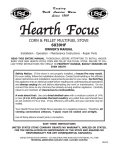
USSC UNITED STATES STOVE COMPANY E U STATES ST OV TED NI “Keeping North America Warm Since 1869” COMPANY American Harvest 2 1 MULTI-FUEL FURNACE MODEL 6500 B A Owner’s Manual Please read this entire manual before installation and use of this appliance. Failure to follow these instructions could result in property damage, bodily injury, or even death. 2 1 Contact your local building or fire officials about restrictions and installation inspection requirements in your area. Save these instructions. UNITED STATES STOVE COMPANY • 227 INDUSTRIAL PARK ROAD • SOUTH PITTSBURG, TENNESSEE 37380 • WWW.USSTOVE.COM FOR TECHNICAL ASSISTANCE: USSC PHONE: (800) 750-2723 FAX: (423) 837-2109 Part No.: 851782 rev A Table of Contents TABLE OF CONTENTS............................................................................................... 2 Safety Precautions............................................................................................ 3 Specifications........................................................................................................ 4 Heating Specifications...................................................................................... 4 Dimensions....................................................................................................... 4 Electrical Specifications.................................................................................... 4 Safety and EPA Compliance............................................................................. 4 Fuel Considerations.......................................................................................... 5 Installation . ......................................................................................................... 5 Installation Options........................................................................................... 6 Floor Protection................................................................................................ 6 Clearances ...................................................................................................... 7 Venting Requirements...................................................................................... 8 Maximum Venting Distance.............................................................................. 8 Pellet Vent Type................................................................................................ 8 Pellet Vent Installation...................................................................................... 8 Pellet Vent Termination..................................................................................... 8 Vent Termination Clearances............................................................................ 9 Through the Wall Installation.......................................................................... 10 Through the Roof/Ceiling Installation............................................................. 10 Primary and Secondary Furnace Illustrations................................................. 11 Operation.............................................................................................................. 12 How Your Furnace Works............................................................................... 12 Damper Control Adjustment............................................................................ 12 Control Panel.................................................................................................. 13 Unit Preparation.............................................................................................. 14 Start-Up Procedure......................................................................................... 14 Shut Down Procedure..................................................................................... 14 Daily Operation............................................................................................... 15 Safety and Convenience Features................................................................. 15 Maintenance......................................................................................................... 15 Exhaust System.............................................................................................. 15 Interior Chambers........................................................................................... 16 Ash Disposal................................................................................................... 16 Check and Clean the Hopper......................................................................... 16 Main Door Gaskets......................................................................................... 16 Fan Motors...................................................................................................... 16 Painted Surfaces............................................................................................ 16 Glass............................................................................................................... 16 Fall Start-Up.................................................................................................... 16 Spring Shut Down........................................................................................... 16 Yearly Servicing.............................................................................................. 16 Repair Parts DIAGRAM & List......................................................................17-18 Wiring Diagram.................................................................................................... 19 Trouble Shooting.............................................................................................. 20 Error codes......................................................................................................... 21 Flashing indicators.......................................................................................... 21 notes..................................................................................................................22-23 2 USSC Safety Precautions IMPORTANT: Read this entire manual before installing and operating this product. Failure to do so may result in property damage, bodily injury, or even death. Proper installation of this furnace is crucial for safe and efficient operation. Install vent at clearances specified by the vent manufacturer. Do not connect the pellet vent to a vent serving any other appliance or furnace. Do not install a flue damper in the exhaust venting system of this unit. Use of outside air is not required for this unit. However, fresh air and return air make-up is required for maximum burn characteristics and heat distribution throughout your house. Contact your local building officials to obtain a permit and information on any additional installation restrictions or inspection requirements in your area. Do not throw this manual away. This manual has important operating and maintenance instructions that you will need at a later time. Always follow the instructions in this manual. This heater is designed and approved as a multi-fuel, such as corn or wood pellets, burning furnace. Use only dried shelled corn with a moisture content of 11% or less (which provides the best results). A pellet type fuel used should have an ash content of 1% or less. If not, efficiency will suffer, and your warranty may be voided. Never use gasoline, gasoline-type lantern fuel, kerosene, charcoal lighter fluid, or similar liquids to start or ’freshen up’ a fire in this furnace. Keep all such liquids well away from the furnace while it is in use. A working smoke detector must be installed in the same room as this product. Do not unplug the furnace if you suspect a malfunction. Turn the ON/OFF SWITCH to ”OFF’ and contact your dealer. Your furnace requires periodic maintenance and cleaning (see ”MAINTENANCE ”). Failure to maintain your furnace may lead to improper and/or unsafe operation. Disconnect the power cord before performing any maintenance! NOTE: Turning the ON/OFF Switch to ”OFF” does not disconnect all power to the electrical components of the furnace. Never try to repair or replace any part of the furnace unless instructions for doing so are given in this manual. All other work should be done by a trained technician. Allow the furnace to cool before performing any maintenance or cleaning. Ashes must be disposed in a metal container with a tight fitting lid. The closed container of ashes should be placed on a noncombustible surface or on the ground, well away from all combustible materials, pending final disposal. The exhaust system should be checked monthly during the burning season for any build-up of soot or creosote. Do not touch the hot surfaces of the furnace. Educate all children on the dangers of a high-temperature furnace. Young children should be supervised when they are in the same room as the furnace. A power surge protector is recommended. This unit must be plugged into a 110 - 120V, 60 Hz grounded electrical outlet. Do not use an adapter plug or sever the grounding plug. Do not route the electrical cord underneath, in front of, or over the furnace. Do not route the cord in foot traffic areas or pinch the cord under furniture. The furnace will not operate during a power outage. If a power outage does occur, check the furnace for smoke spillage and open a window if any smoke spills into the room. The feed door must be closed and sealed during operation. Never block free airflow through the open vents of the unit. Keep foreign objects out of the hopper. The moving parts of this furnace are propelled by high torque electric motors. Keep all body parts away from the auger while the furnace is plugged into an electrical outlet. These moving parts may begin to move at any time while the furnace is plugged in. Do not place clothing or other flammable items on or near this furnace. This appliance is not intended for commercial use. USSC 3 Specifications Heating Specifications Input BTU/Hr1 50,000 to 105,000 BTU/hr. Heating Capacity2 1,200 - 2,800 sq. ft. Fuel Burn Rate 5.0 - 13.0 lbs./hr. 3 Burn Time (lowest setting) 70 hours continuous Hopper Capacity 320 lbs BTU output will vary depending on the quality and type of fuel. Use PFI listed fuels for the best results. Heating capacity will vary depending on floor plan layout of your home, degree of insulation, and the outside temperature. 3 Fuel size may effect the actual rate of fuel feed and burn times. Fuel feed rates may vary by as much as 20%. Use PFI listed fuel for best results. 1 2 Dimensions Height 43-1/8 in. Width 28-1/2 in. Depth 39-1/2 in. 250 lbs. Weight Electrical Specifications Electrical Rating Watts (operational) 110-120 volts, 60 HZ, 9.5 Amps 1150 (max. approx.) SAFETY AND EPA COMPLIANCE Your American Harvest Furnace has been safety tested and listed to UL 391, ASTM 1509, and(UM) 84-HUD, byOMNITest Laboratories, Inc. Portland, Oregon USA. It is also exempt from EPA Phase II requirements. 4 USSC Fuel Considerations SHELLED CORN (Dry, preferably corn with 11% or less moisture content) • Optimum moisture content of corn should be 11% or less. Wet corn will rapidly deteriorate furnace components, reduce efficiency and void all warranties. Purchase a moisture tester if in doubt. • Corn must be clean and free from debris. Never burn corn right from the field. Damage caused by dirty corn is not covered by the product warranty. Ask for clean filtered bagged corn only. Stalk parts, excessive fines and cob remnants will clog the auger. • NEVER BURN SEED CORN IN YOUR FURNACE. Seed corn is treated with chemical pesticides that are harmful or fatal if swallowed, therefore, seed corn is dangerous to have in the house, especially where children can reach it. • Never burn “Deer Corn.” It frequently contains molasses/sugars. • Store your corn supply in a dry place and keep bags or container sealed to prevent your corn from absorbing excess moisture. Test the moisture content periodically to ensure the proper dryness. • There are many varieties of corn grown around the world. Each variety has unique characteristics including the shape and size of the kernel. Your furnace will burn more consistently with a small to midsize kernel corn. If the kernel size of the corn varies greatly or if you switch sources frequently, you will get a less consistent burn. Therefore, purchasing corn from the same source will help achieve a more consistent burn. DO NOT USE CORN WITH A HIGH WAX CONTENT! • Oyster shell is highly recommended for best burn operations and to reduce clinker build-up WOOD PELLETS • As with corn, be consistent in your pellet supplier. Pellets will vary in content and burn characteristics from supplier to supplier. A consistent supply of pellets will result in a more consistent and efficient burn. • Check your pellets for foreign objects. Your furnace warranty will not cover damage done to your furnace due to foreign objects in the fuel supply. • Store your pellets in a dry place to prevent them from absorbing added moisture. • To decrease sawdust buildup, the hopper will need to be vacuumed out after every 6-8 bags of pellets or more often if the pellets are poor quality. You may have to screen each bag of pellets if sawdust becomes a problem. • Wood Pellets vary in size and ash content from less than 1% to 3% or more. Your furnace will burn more efficiently with small to midsize pellets. Low ash content pellets will allow you to burn the furnace longer between cleanings. Only wood pellets manufactured to the Association of Pellet Fuel Industries (A.P.F.I.) standard for residential pellet fuels are recommended. Performance will suffer if nonstandard pellets are used. Consult your local American Harvest reseller for more information on approved wood pellet fuel. CAUTION: DO NOT PLACE SUCH FUELS WITHIN THE SPACE HEATER’S INSTALLATION CLEARANCES OR WITHIN THE SPACE REQUIRED FOR CHARGING AND ASH REMOVAL. USSC 5 Installation Installation Options Read this entire manual before you install and use your Multi-Fuel Furnace. Failure to follow instructions may result in property damage, bodily injury, or even death! (See specific installation details for clearances and other installation requirements) As a Primary Furnace—the unit functions independently of any other system. The “Room Air” blowers will come on when the plenum and Exhaust temperatures reach a preset point on the furnace’s circuit board (PCB). Unit may also be used as a stand-alone shop heater As a Secondary (Add-On) Furnace—the unit aids an existing gas/electric furnace helping cut down on operation time. It is recommended that only a authorized technician install your Multi-Fuel Furnace, preferably an NFI certified specialist. IMPROPER INSTALLATION: The manufacturer will not be held responsible for damage caused by the malfunction of a furnace due to improper venting or installation. Call (800) 750-2723 and/or consult a professional installer if you have any questions. ADDITIONAL ITEMS NEEDED FOR INSTALLATION • UL listed 3 inch or 4 inch (Depending on application) “PL” pellet venting exhaust system. • Air distribution duct work. Transition from 4.5 inch x 18.5 inch rectangle to 10 inch round is provided. • Air filter (Optional). Size: 10 x 20 x 1 • Floor Protection (If not installed on a non-combustible floor) • Air return vent from the house to the room where furnace is installed. • Fresh air for combustion if located in a small, tightly constructed room. Floor protection This unit must be installed on a non-combustible floor surface. If a floor pad is used, it should be UL listed or equal. The floor pad or non-combustible surface should be large enough to extend a minimum of 6-inches in front, 6-inches on each side, and 1-inch behind the furnace for horizontal termination. Floor protection must extend under and 2-inches to each side of the chimney tee for an interior vertical termination. A Floor Protector of 1 inch thick is recommended for this installation. 6 USSC Installation Clearances NOTE: Distance on the left-hand side of your Multi-Fuel Furnace is set at 24 inches for suitable access to the control panel and for fuel loading. This distance may be less, but not less than 7 inches. USSC 7 Installation Venting requirements Install vent at clearances specified by the vent manufacturer. Do not connect the pellet vent to a vent serving any other appliance or furnace. Do not install a flue damper in the exhaust venting system of this unit. The following installation guidelines must be followed to ensure conformity with both the safety listing of this furnace and to local building codes. IMPORTANT! This unit is equipped with a negative draft system that pulls air through the burn pot and pushes the exhaust out of the dwelling. If this unit is connected to a flue system other than the way explained in this manual, it will not function properly. Maximum venting distance Installation MUST include at least 3-feet of vertical pipe. This will create some natural draft to reduce the possibility of smoke or odor during appliance shutdown and keep exhaust from causing a nuisance or hazard by exposing people or shrubs to high temperatures. The maximum recommend vertical venting height is 12-feet for 3-inch type “PL” vent. Total length of horizontal vent must not exceed 4-feet. Use no more than 180 degrees of elbows (two 90-degree elbows, or two 45-degree and one 90-degree elbow, etc.) to maintain adequate draft. Pellet vent type A UL listed 3-inch or 4-inch type “PL” pellet vent exhaust system must be used for installation and attached to the pipe connector provided on the back of the furnace (use a 3-inch to 4-inch adapter for 4-inch pipe). Use 4-inch vent if the vent height is over 12-feet or if the installation is over 2,500 feet above sea level. We recommend the use of Simpson Dura-Vent® or Metal-Fab® pipe (if you use other pipe, consult your local building codes and/or building inspectors). Do not use Type-B Gas Vent pipe or galvanized pipe with this unit. The pellet vent pipe is designed to disassemble for cleaning and should be checked several times during the burning season. Pellet vent pipe is not furnished with the unit and must be purchased separately. Pellet vent installation The installation must include a clean-out tee to enable collection of fly ash and to permit periodic cleaning of the exhaust system. 90-degree elbows accumulate fly ash and soot thereby reducing exhaust flow and performance of the furnace. Each elbow or tee reduces draft potential by 30% to 50%. All joints in the vent system must be fastened by at least 3 screws, and all joints must be sealed with HI-TEMP RTV silicone sealant to be airtight. The area where the vent pipe penetrates to the exterior of the home must be sealed with silicone or other means to maintain the vapor barrier between the exterior and the interior of the home. Vent surfaces can get hot enough to cause burns if touched by children. Noncombustible shielding or guards may be required. Pellet vent termination Do not terminate the vent in an enclosed or semi-enclosed area, such as; carport, garage, attic, crawl space, under a sundeck or porch, narrow walkway, or any other location that can build up a concentration of fumes. The termination must exhaust above the outside air inlet elevation. The termination must not be located where it will become plugged by snow or other materials. 8 USSC Installation Vent termination clearances: A Minimum 4-foot clearance below or beside any door or window that opens. B Minimum 1-foot clearance above any door or window that opens. C Minimum 3-foot clearance from any adjacent building. D Minimum 7-foot clearance from any grade when adjacent to public walkways. E Minimum 2-foot clearance above any grass, plants, or other combustible materials. F Minimum 3-foot clearance from a forced air intake of any appliance. G Minimum 2-foot clearance below eaves or overhang. H Minimum 1-foot clearance horizontally from combustible wall. I Must be a minimum of 36-inches above the roof and 24-inches above the highest point of the roof within 10-feet. VENT TERMINATION CLEARANCES USSC 9 Installation THROUGH THE WALL INSTALLATION (Recommended installation) To vent the unit through the wall, connect the pipe adapter to the exhaust motor adapter. If the exhaust adapter is at least 18-inches above ground level, a straight section of pellet vent pipe can be used through the wall. Your furnace dealer should be able to provide you with a kit that will handle most of this installation, which will include a wall thimble that will allow the proper clearance through a combustible wall. Once outside the structure, a 3-inch clearance should be maintained from the outside wall and a clean out tee should be placed on the pipe with a 90-degree turn away from the house. At this point, a 3-foot (minimum) vertical section of pipe should be added with a horizontal cap, which would complete the installation. A support bracket should be placed just below the termination cap or one every 4-feet to make the system more stable. If you live in an area that has heavy snowfall, it is recommended that the installation be taller than 3-feet to get above the snowdrift line. This same installation can be used if your furnace is below ground level by simply adding the clean-out section and vertical pipe inside until ground level is reached. With this installation you have to be aware of the snowdrift line, dead grass, and leaves. We recommend a 3-foot minimum vertical rise on the inside or outside of the house. The “through the wall” installation is the least expensive and simplest installation. Never terminate the end vent under a deck, in an alcove, under a window, or between two windows. We recommend Simpson Dura-Vent® or Metal-Fab® kits. Through the roof/Ceiling Installation When venting the furnace through the ceiling, the pipe is connected the same as through the wall, except the clean-out tee is always on the inside of the house, and a 3-inch adapter is added before the clean-out tee. You must use the proper ceiling support flanges and roof flashing (supplied by the pipe manufacturer; follow the pipe manufacturer’s directions). It is important to note that if your vertical run of pipe is more than 15-feet, the pellet vent pipe size should be increased to 4-inches in diameter. Do not exceed more than 4-feet of pipe on a horizontal run and use as few elbows as possible. If an offset is required, it is better to install 45-degree elbows rather than 90-degree elbows. 1 2 3 4 5 6 7 8 9 10 11 12 13 10 Vertical Cap Storm Collar Adjustable Roof Flashing Cathedral Ceiling Support Box Pipe 45° Elbow 90° Elbow Horizontal Cap Wall Thimble Black Ceiling Support Firestop Spacer Single Tee with Clean-Out Adapter Tee Support Bracket Double Tee with Clean-Out Adapter USSC Installation PRIMARY FURNACE SECONDARY (ADD-ON) FURNACE When installed as a secondary furnace, a Duct Damper must be installed between the air discharge of the 6500 furnace and the primary (Gas, Electric, etc.). This duct damper prevents the air from the primary furnace from back flowing to the secondary furnace. Damper must be a mechanical (spring return) style with a simple closure switch to determine if the damper is opened or closed. The damper will connect to the multi-fuel furnace’s printed circuit board (PCB). See wiring diagram in this manual. USSC 11 Component Location 12 USSC Operation Control Panel Turning the furnace OFF/ON, as well as adjustments for the fuel feed rate and room fan speed are performed by pressing the appropriate button(s) on the control panel which is located on the lower left-hand side of your American Harvest furnace. This unit can be changed between an automatic operation or a manual operation. The controller comes default in the automatic mode. Pressing the “ON” button on the control panel will begin the start-up sequence for the furnace. Fuel will begin to feed through the auger feed system after 3 minutes. Pressing and holding the “ON” button will rotate the auger continuously until button is released, which feeds additional fuel. Heat Range Room Fan Draft Fan Pressing the “OFF” button on the control panel will cause the furnace to enter its shut-down sequence. The fuel feed system will stop pulling fuel from the hopper and, once the fire goes out and the furnace cools down, the fans will stop running. Pressing the “Heat Range” arrows, up or down, will adjust the amount of fuel being delivered to the burnpot. This unit comes preset from the factory to burn shelled corn. The display will show a “Cr” in front of the heat setting. If burning only wood pellets, this setting must be changed. To change, press and hold the heat range up and down buttons simultaneously for approximately 2-3 seconds. The display will change from “Cr” to “Pr”. If burning a pellet(50%) and corn(50%) mix, the “Cr” setting will work the best for optimum performance. Aux. Auto ON OFF Auger Delay Mode Manual The draft fan (exhaust) will come on as soon as the “ON” button is pressed. The fan will automatically adjust its speed in accordance to the heat range setting. However, this speed can be manually operated by pressing the “Draft Fan” arrows up or down. “Draft Fan” when pressed, the display will show “Df-A”, which is automatic. Press the arrows again to adjust fan speed. When the furnace is in the manual mode, the optional thermostat will not properly control the unit. When adjusting the Draft Fan setting, try only 1 setting above or below the heat setting. The room fan(s) will come on once the unit has reached operating temperature. The room fans will automatically adjust their speed in accordance with the heat range setting. By pressing the “Room Fan” buttons, the display will show “RfA” which is automatic or how many fans are running. The “Aux” button is for Agitator operation. When the unit is “OFF”, pressing the “Aux” arrows will rotate the agitator for easy removal for cleaning. The agitator, when in Automatic mode, will operate at set intervals. However, these can be changed by pressing the arrows on the “Aux” button. The agitator can be adjusted from 0 to 9, setting “0” is off and setting “9” is high. The “Auger Delay” button can be used to pause rotation of the Auger and Agitator for approx. 1 minute. This can be cancelled by pressing the “ON” button. The “Mode” button is used to switch between manual and automatic mode. When in auto mode, the fans, auger, and agitator will operate at preset intervals unless changed manually using the buttons mentioned above. When in manual mode, the draft fan (exhaust) will operate at full speed (100%), so the air must be controlled with the damper just below the viewing door. During normal operation, the unit is constantly monitored for problems. In the event of an error condition, the unit will stop and an error will be displayed. See the list of error codes found at the end of this manual. USSC 13 LIGHTING INSTRUCTIONS CAUTION: DO NOT USE CHEMICALS OR FLUIDS TO START THE FIRE HOT WHILE IN OPERATION. KEEP CHILDREN, CLOTHING AND FURNITURE AWAY. CONTACT MAY CAUSE SKIN BURNS. Before lighting your heater for the first time, make sure that all items are out of the hopper, ash pan and firebox area. Press the “On” button and allow your heater to run for at least 4 minutes, to check for proper operation. Once your heater is started, you will notice the draft fan starts immediately. If you press the “Heat Setting” button up, the draft fan changes speed, increasing speed the higher the heat setting. After 3 minutes, the auger and agitator will start rotating. Note: The room fans will not operate until your furnace reaches preset operating temperatures. If proper operation of your heater is confirmed, you can add fuel to the hopper and allow the auger to purge the fuel to the firepot. START-UP PROCEDURE • Turn the Heater to the “OFF” position and place a small handful of wood pellets or fire starting pellets (Pellets that already contain fire starter) in the firepot. NOTE: Even if you are burning corn or other fuels in your unit, wood pellets make an excellent source of starter fuel. Corn takes too much starter to properly ignite and get up to temperature. • Squirt only a small amount of fire starter gel on top of the wood pellets (NOT necessary if using fire starting pellets). • Light the fire starter and wait approx. 1-minute for it to start actively burning. • Press the “On” button, adjust the heat range to read “Cr-3” or “Pr-3” depending on fuel setting. Pull the damper out approximately 1 inch. This will automatically match your feed rate with the proper combustion air. As you increase the heat setting, your feed rate and combustion air increase together. Once the unit reaches operating temperature, you may reduce the heat setting. • Three minutes after turning the stove “On”, the auger will begin feeding fuel into the firepot along with the agitator turning. You should have the starting fuel completely burning in the firepot as the agitator rotates. NOTE: If the starting fuel is not burning hot enough, you may see the fire begin to go out as new fuel is being added. If this occurs, pressing the “Auger Delay” button will allow the auger to pause for 1 minute. Pressing the “ON” button will resume the auger if 1 min. is too long. If not enough fuel is the reason for not burning, pressing and holding the “ON” button will allow the auger to run continuously until you release the button. • Once the fuel starts burning aggresively, you can adjust the heat setting to your desired range. Make sure that you pull the damper out approximately 1 inch. It may need to be pulled out more for higher heat settings. Try opening a 1/4 inch at a time. • As you begin to have better understanding of how the heater operates and the amount of heat you require, you can adjust the heat settings up or down to your satisfaction. • Never use gasoline, gasoline-type lantern fuel, kerosene, charcoal lighter fluid, or similar liquids to start or “freshen up” a fire in this heater. Keep all such liquids well away from the heater while it is in use. • Overfire Protection - If the heater is being overfired, burned too hot, the heater will automatically shutdown to avoid damage to components in the heater. Refer to “Lighting Instructions” for proper use. SHUT-DOWN PROCEDURE WARNING: Never shut down this unit by unplugging it from the power source. Press the “OFF” button on the control panel to put the furnace in shut down mode. At this time, the red light above the “OFF” button will illuminate. Once this is done, the auger will stop feeding fuel, but the room air fan(s) and draft fan will continue to operate. When the internal temperature of the unit drops below the factory preset temperatures, the room air fans and draft fan will cease to operate. The red light will then shut off and the unit will be completely shut down. The hotter the unit is during its operation, the longer it will take for the furnace to complete the shut down cycle. If the furnace stays on for more than 2 hours after pressing the “OFF” button and you are sure that the fire is out, the furnace can be unplugged from the outlet. After approximately 10 seconds, the unit can be re-connected to the power source and the control board will be reset. 14 USSC Operation DAILY OPERATION The hopper and furnace top will be hot during operation; therefore, you should always use some type of hand protection when refueling your furnace. Never place your hand near the auger while the furnace is in operation. In the event of a power outage, the furnace will not function. It is very important that unit be vented properly, as the natural draft is needed to clear the smoke from the furnace during a power outage. If the unit was “ON” when the power outage occurred, one of the following will take place when power is restored: 1.) If the furnace is still warm, it will resume feeding fuel and continue to operate normally. If the fire has gone out, you will have to press the “OFF” button and then the “ON” button again to begin a new start-up sequence. 2.) If the furnace has cooled-off, it will reset to its “OFF” condition. At this point, you may press the “ON” button to begin a new start-up sequence. NOTE: The unit will also shut down in the event of an draft fan failure; if this is the case, the unit will not re-start and you must contact Customer Service at (800) 750-2723. safety and Convenience features Your American Harvest incorporates a safety pressure switch that helps ensure that everything is in proper working order before feeding fuel to the burn pot. Because the furnace works using an induced draft pressure, the furnace will not continue to operate if the viewing door is left open; or if the draft fan fails or the exhaust system is blocked. The temperature limit control will prevent your furnace from operating at abnormally high temperatures. Should the furnace temperature begin to approach the factory pre-set limit, the temperature limit control will automatically slow down the auger feed rate until the temperature returns to a normal condition. Both room air fans will operate at full speed also until the furnace returns to normal operating temperatures. If your furnace continues to cut back because it is reaching the temperature limits, reduce the “heat setting” to the next lower setting. Maintenance Failure to clean and maintain this unit as indicated can result in poor performance and safety hazards. Unplug your stove’s electrical cord prior to removing the back panel or opening the exhaust system for any inspection, cleaning, or maintenance work. Never perform any inspections, cleaning, or maintenance on a hot furnace. Do not operate furnace with broken glass , leakage of flue gas may result. Exhaust System The by products of combustion contain small particles of fly ash. Fly ash will collect in the exhaust venting system and restrict the flow of flue gases. Incomplete combustion, such as during startup, shutdown, or incorrect operation of the furnace will lead to soot formation which will collect in the exhaust system. Therefore, it is important that the exhaust system be inspected and cleaned at least monthly during the burning season. Check the clean out tees periodically to determine the required cleaning schedule. 3 or 4-inch chimney brushes are available for chimney cleaning. If the exhaust system or outside air pipes have screens on them, frequently clean the screen. A plugged screen will shut off combustion air and cause a fire to die or burn poorly. USSC 15 Maintenance Interior Chambers Open the Ash Cleanouts and scrap all ash into the ash pan. Open the damper and allow the ashes to fall into the ash pan. The damper may need to be slide in and out several times to clear any ash build-up. This may need to be done daily depending on fuel consumption. Be sure the ash cleanouts located on either side of the damper are completely closed before operating. Periodically remove and clean the burnpot and the area inside the burnpot housing. In particular it is advisable to clean out the holes in the burnpot to remove any build up that may prevent air from moving through the burn pot freely. Placing the Burnpot and the Agitator in a bucket of water and allowing to soak will help with the clinker build-up and removal. Remove the two cleanout slides on each side of the burnpot at the rear of the burn chamber to clean out all ash. Remove the exhaust clean out plate located behind the ash pan and clean the exhaust duct of all ash. If a vacuum is used to clean your furnace, we suggest using a vacuum designed for ash removal. Some regular vacuum cleaner (i.e. shop vacs) may leak ash into the room. Ash Disposal Ashes should be placed in a metal container with a tight fitting lid. The closed container of ashes should be placed on a noncombustible floor or on the ground, well away from all combustible materials, pending final disposal. If the ashes are disposed of by burial in soil or otherwise locally dispersed, they should be retained in the closed container until all cinders have been thoroughly cooled. Check and Clean the Hopper Check the hopper periodically to determine if there is any fuel or fuel matter that is sticking to the hopper surface. Clean as needed. Gaskets Inspect the main door and glass window gaskets periodically. The main door may need to be removed to have frayed, broken, or compacted gaskets replaced by your Authorized “American Harvest” Dealer. Also, be careful not to damage the gaskets on the backside of the cleanouts on the front of the unit. If gaskets become torn or damaged, they must be replaced. FAN Motors Clean the air holes on the motors of both the draft fan and room air fans annually. Remove the draft fan from the exhaust duct and clean out the internal fan blades as part of your fall start-up. A new gasket may be purchased from U S Stove’s Parts Department. Replace the customer supplied air filter on the back of the furnace on a regular basis if installed. Painted Surfaces Painted surfaces may be wiped down with a damp cloth. If scratches appear, or you wish to renew your paint, contact your Authorized “American Harvest” Dealer to obtain a can of suitable high-temperature paint. GLASS We recommend using a high quality glass cleaner. Should a build up of creosote or carbon accumulate, you may wish to use 000 steel wool and water to clean the glass. In the event you need to replace the glass, only high temperature ceramic glass of the correct size and thickness may be used. Contact your Authorized “American Harvest” Dealer to obtain this glass. FALL START UP Prior to starting the first fire of the heating season, check the outside area around the exhaust and air intake systems for obstructions. Clean and remove any fly ash from the exhaust venting system. Clean any screens on the exhaust system and on the outside air intake pipe. Turn all of the controls on and make sure that they are working properly. This is also a good time to give the entire furnace a good cleaning throughout. SPRING SHUTDOWN After the last burn in the spring, remove any remaining fuel from the hopper and the auger feed system. Scoop out the fuel and then run the auger until the hopper is empty and fuel stops flowing (this can be done by pressing the “ON” button with the viewing door open). Vacuum out the hopper. Thoroughly clean the burnpot, and firebox. It may be desirable to spray the inside of the cleaned hopper with an aerosol silicone spray if your furnace is in a high humidity area. The exhaust system should be thoroughly cleaned. YEARLY SERVICING A yearly servicing and cleaning by your Authorized “American Harvest” Dealer is recommended. A fee may be charged for this service. 16 USSC Parts Diagram 52 51 33 5 32 31 30 29 50 49 4 6 27 62 26 64 28 25 63 34 23 24 43 44 35 47 42 27 54 58 22 53 57 48 24 28 39 38 36 37 55 45 55 28 46 27 40 41 56 2 18 19 20 21 59 3 8 9 1 60 10 13 14 11 61 16 12 17 15 7 17 USSC Parts List Item Part No. Title 1 2 3 4 5 6 7 8 9 10 11 12 13 14 15 16 17 18 19 20 21 22 23 24 25 - 26 27 28 29 30 31 32 33 34 35 891481 891471 891375 891376 891438 80554 69524 83508 25080 891372 891262 891440 891461 83551 891445 88047 891327 891364 891457 891485 89954 891455 40501 83529 88111 891232 891220 891132 83534 86620 83533 80488 25427 891284 80530 88127 Top Cover Weldment Lid Weldment Side Panel, Right Weld., Left Side Panel Access Panel, Back Assembly, Circuit Board Assembly, Feed Door 5/16-18 x 3/4 Bolt Latch, Door Pad, Door Hinge (Threaded) Baffle 3 Cleanout, Ash Cover, Exhaust Cleanout Wing Nut, 1/4-20 Brass Ash Pan Assembly Rope Gasket, 3/4 x 1/8 w/Adhesive Latch, Mini-Lift & Turn Hearth Plate Cleanout, Ash (Lower) Weldment, Damper Spring Handle (Small) Weldment, Burnpot Agitator, Cast Hairpin Gasket, Agitator Bracket Assy, Agitator Bracket (Items 26, 27, 28) Mounting Bracket for 3/4” Bushing 3/4” Bushing Retaining Ring Drive Shaft Roll Pin Drive Motor Retainer, Agitator Motor Access Panel, Agitator Motor 800 CFM Room (Distribution) Fan Gasket, Blower Qty. Item Part No. Title Qty. 1 36 80495 120 CFM Draft Fan 1 1 1 37 88123 Gasket, Blower 120 CFM 1 38 1 891491 Transition, Exhaust Blower 1 39 1 80531 RTD, Platinum 1 40 891269 Assy, Auger Housing 1 1 891141 Auger 1 41 1 1 42 891248 Weldment, Bottom Plate Retainer 1 43 1 891195 Bracket, Drive Motor 1 44 2 891169 Hose, Heater 2 - 69513 Assy, Bushing Retainer Bot. (Items 45, 26, 28) 1 1 45 891190 Plate, Bottom Bushing 1 2 2 - 69514 Assy., Bushing Retainer Top. (Items 46, 26, 28) 1 1 1 46 891189 Plate, Top Bushing 2 47 1 891180 Cover, Auger 1 48 80529 Auger Motor 1 4 ft 1 49 891470 Hopper Assembly PARTSLIST Hopper LidQTY 1 50 80491 Micro-Switch, ITEM 2 PARTNO TITLE 1 N/S Harness, Lid Switch 1 80499 Wiring 1 25507 PAINTED,FEEDDOOR 1 2 N/S 1 80497 Wiring Harness, Main 2 25492 PAINTED,DOORHANDLE 1 1 1 51 80462 Recepticle, 3 Prong 3 83506 3/8x1-1/4ROLLPIN 1 52 1 80461 Cord, Power Supply 1 4 891053 DOORGLASSW/OLOGO 1 1 1 53 891187 Brkt, Pressure Switch/PCB 5 88066 GASKET,5/8ROPE 1 1 1 54 80549 Pressure Switch, Dual Port 6 288087 N/S GLASSGASKET(1x3/16) 1 2 83905 3/4” Snap Bushing 7 125520 55 1 RETAINER,BOTTOMGLASS 1.2 ft 891121 Hose, Silicone 8 125521 56 1 RETAINER,TOPGLASS 1 89586 Nipple, Auger 9 183278 57 4 #10FLATWASHER 89603 1 Brass Connector 2 83537 Hose Clamp (#4) 10 383202 58 4 MACHINESCREW 1 80501 Thermistor (Long Lead) 1 11 389574 59 HANDLE,SPRING 1 891296 Transition Duct, 10” Round1 12 125393 60 GLASSRETAINER 1 1 61 891374 Access Panel, Plenum 62 1 1 25681 Primary Blower, Isolation Panel 1 1 63 25680 Secondary Blower, Isolation Panel 64 1 1 25683 Bridge Plate, Isolation Panel N/S = Not Shown 2 2 10 8 9 5 1 3 2 11 12 6 4 7 PARTS LIST Item Part No. Title 8 25521 Top Glass Retainer 1 2 3 4 5 6 7 18 25507 25492 83506 891053 88066 88087 25520 Feed Door Handle, Door 3/8 x 1 1/4 Roll Pin Door Glass w/o Logo 5/8” Rope Gasket Glass Gasket (1 x 1 3/16) Bottom Glass Retainer Qty. 1 1 1 1 4.5 ft 3 ft 1 1 Item Part No. 9 83278 10 83202 11 89574 12 25393 N/S 25080MB N/S 83508 N/S 83338 N/S - Not Shown Title Washer Machine Screw Spring Handle Retainer, Glass (Alternate For 7 & 8) Door Latch 5/16-18 x 1-3/4 Bolt 5/16-18 Lock-Nut Qty. 4 4 1 1 1 1 1 USSC Wiring Diagram Amendment USSC 19 Trouble Shooting Disconnect the power cord before performing any maintenance! NOTE: Turning the ON/OFF Switch to ”OFF” does not disconnect all power to the electrical components of the furnace. Never try to repair or replace any part of the furnace unless instructions for doing so are given in this manual. All other work should be done by a trained technician. PROBLEM CAUSE: Too rich air/fuel mixture Orange, lazy flame, excessive fuel build-up in the burnpot • Clean out the burnpot and burnpot housing • Adjust the air damper on the front of the furnace to an open position. • Make sure that the viewing door is closed and sealed properly. If not, check door gasket.. • Check that all outside connections are clear of any obstructions. • Check the exhaust system; clean as needed. PROBLEM CAUSE: Burnpot burns out of fuel Fire goes out or furnace shuts down. • Hopper is empty, refill the hopper. • Loss of draft pressure. Make sure that the viewing door is closed and sealed properly. Check that all outside connections are clear of any obstructions. Check the exhaust system; clean as needed. • Check that the pressure switch connection to the firebox is free of ash or clear of obstructions. • Auger system is jammed or there is a “bridging” of the fuel in the hopper, preventing fuel from flowing into the auger feed system. • Stove may be shutting down to an over temperture condition. PROBLEM Viewing window becoming black shortly after start-up. CAUSE: Not enough combustion air; Fuel has too much moisture. • Adjust the air damper to a more open position. • Use a fuel with less moisture content PROBLEM CAUSE: Not enough combustion air; Fuel has too much moisture. “Black Popcorn” is present in the burn chamber. • Adjust the air damper to a more open position. • Use a fuel with less moisture content • Stove might be cycling excessively due to temperature cut backs. • Reduce heat setting PROBLEM CAUSE: Chemical reaction between the starch in corn and the heat. “Clinkers” form in burnpot. • Add calcium carbonate (aka chicken scratch or oyster shell). • Adjust air mixture • Use corn with less moisture or starch. PROBLEM CAUSE: Unit is reaching the “Almost Over-temp” preset. Unit cycles up and down when on the “HIGH” heat setting. • Adjust the heat range to lower setting. • Fuel burns hot causing the furnace to cycle between high setting and lower settings. PROBLEM CAUSE: Corn is wet or it has a very high moisture content. Corn builds up and is not burning completely. Steam is coming from the corn. • Use corn with a moisture content of 11% or less for best results. 20 USSC Error Codes Below is a chart describing the Error Codes that might be displayed if an error occurs with your furnace. Error Code Error Descrption Possible Causes Err1 The high limit temperature sensor has tripped. • • • • Inadequate ventilation. Room fan failure. Exhaust Blockage. Electrical Open in the over temperature switch or wiring. Err2 Furnace ran out of fuel during normal operation. • • • • Hopper Empty. Auger output failure or jam. Flame of fuel quality caused fire to burn too slowly or go out. Electrical Open in low temperature switch or wiring. Err3 The furnace was unable to reach the Room Fan On temperature within the startup time. • Flame or Fuel quality caused the fire to burn too slowly or go out. • Auger output failure or jam Hopper empty on startup. Err4 The power failed while the furnace was • Electrical Open in low temperature switch or wiring. hot, and when power was restored, • Power loss the fire was out. • Electrical Open in low temperature switch or wiring. Err5 The Auger output fuse has blown. • Auger motor jammed or bad. Err6 The Agitator output fuse has blown. • Agitator motor jammed or bad. Err7 The Draft Fan (Exhaust Fan) output fuse has blown. • Draft Fan motor jammed or bad. Err8 The Room Fan blower output fuse has blown. • Room fan motor jammed or bad. Flashing Indicators Several situations or events are indicated in normal operation by blinking display indicators or segments in the display: Flashing On Indicator : This means that the furnace is in the “Lighting” state waiting for either a 3 minute timeout to begin burning or for the furnace to reach the warm temperature whichever comes first. Flashing Off Indicator : This indicates that the furnace is in the “Shutdown” state waiting for the OFF button, or for a 15 minute period after the furnace was turned off, or for the furnace to cool down, or for the door to be closed. Flashing dash “-“ in Heat Range Display : This indicates that the furnace is in the normal run mode and is ramping from the current heat range setting to the target heat range setting. Once the ramp is complete, the “-“ will stop flashing. For ramping from heat range 1 to 3, the default time is 90 seconds between internal settings. Flashing Automatic Mode Indicator : This indicates that the furnace is in normal operation and is running in the automatic mode. However, either the Draft Fan or Auxiliary setting is manually configured. Flashing Draft Fan Setting Indicator : This indicates that the furnace is in normal operation and that the vacuum sensor detects a loss of pressure either because the door is open or because there is a negative pressure in the room with respect to the exhaust. Flashing Heat Range Setting Indicator : This indicates that the furnace is in normal operation and that an overtemperature condition exists causing the fuel to stop. Flashing Auger Delay Indicator : This indicates that the furnace is in normal operation and that the hopper lid is open. USSC 21 Notes 22 USSC Notes USSC 23 How to order repair parts This manual will help you obtain efficient, dependable service from your KING OR ASHLEY, and enable you to order repair parts correctly. Keep this manual in a safe place for future reference. When writing, always give the full model number which is on the nameplate attached to the heater. When ordering repair parts, always give the following information as shown in this list: 1. The part number 2. The part description 3. The model number: 6500 4. The serial number:____________________ United States Stove Company 227 Industrial Park Road P.O. Box 151 South Pittsburg, TN 37380 (423) 837-2100 WWW.USSTOVE.COM 24 USSC