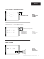
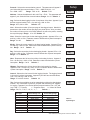
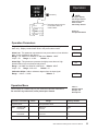
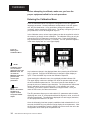
1
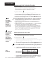
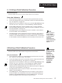
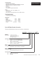
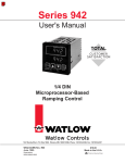
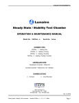
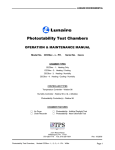
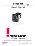
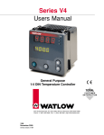
Series 945
High/Low
Limit Control
User's Manual
Watlow Controls, 1241 Bundy Blvd., P.O. Box 5580, Winona, MN 55987-5580, Phone: 507/454-5300, Fax: 507/452-4507
W945-LMT1-9345
November, 1993
$10.00
Made in the U.S.A.
Printed on Recycled Paper
WATLOW Series 945 High/Low Limit User's Manual
1
Starting Out
Starting Out With The Series 945,
A Microprocessor-Based Limit Control
Figure 1 Series 945 Input and
Output Overview
Signal to Drive
an Audible Alarm
Single Input Type J, K, T,
N, C or Pt2
Thermocouple,
RTD or Process
RS-422A, RS423A
(RS-232C compatible), or EIA-485
Optional Computer
Interface
Dual Alarm
Relay Outputs
General Description
Welcome to the Series 945, a 1/4 DIN microprocessor-based, audible alarm,
dual alarm relay, single input, high-low limit control. The 945 accepts a Type J,
K, T, N, C or Platinel 2 thermocouple, RTD, or process input.
The upper display provides process temperature information while the lower
display provides alarm status. Output 1 is a DC signal output used to drive an
external audible alarm. Output 2 and 3 are alarm relays that de-energize when
a limit condition exists.
Operator-friendly features include automatic LED indicators to aid in monitoring
and set-up, as well as a calibration offset at the front panel. The Series 945
automatically stores all information in a non-volatile memory.
2
WATLOW Series 945 High/Low Limit User's Manual
Power Wiring
How to Wire the Series 945
945A-2CA2-AJAP
Terminal
The Series 945 wiring is illustrated by model number option. Check the unit
sticker on the control (see right) and compare your model number to those
shown here and also the model number breakdown in the Appendix of this
manual.
Series 945 internal circuits appear "inside" the line drawing of the 945, while
connections and terminal designations appear "outside" the line drawing. All
outputs are referenced to a de-energized state. The final wiring figure is a
typical system example.
When you apply power without sensor inputs on the terminal strip, the Series
945 will display "- - - -" in the Upper display, and a "0" in the Lower display.
Press the ALARM CLEAR key twice, and an ER 7 is displayed for one second.
This error indicates an open sensor or A/D error. Remove power to the control
and connect the sensor properly, see Page 4 and 5. All wiring and fusing must
conform to the National Electric Code and to any locally applicable codes.
Fuse
1
2
3
4
5
6
7
8
9
10
11
12
13
14
15
16
17
18
19
20
21
22
23
24
25
26
27
Function
4-20, 0-5 +
4-20, Jumper to 3
4-20, 0-5 S1 RTD
S2 RTD
S3 RTD
T.C. +
Not Used
T.C. L1 240V
L1 120V
L2
Earth Ground
Not Used
Not Used
DC Output #1
DC +
Not Used
Not Used
Not Used
Not Used
Not Used
Not Used
Com.
N.O. or N.C.
Com.
N.O. or N.C.
Alarm #2
Alarm #1
Figure 2 120 VAC Power
Wiring
11
12
L1
13
Earth Ground
L2
120 VAC
WARNING:
Fuse
L1
10
To avoid potential
electric shock, use
National Electric
Code (NEC) safety
practices when
wiring and connecting this unit to a
power source and to
electrical sensors or
peripheral devices.
Fuse
L2
12
13
Earth Ground
240 VAC
Figure 3 240 VAC Power
Wiring
WATLOW Series 945 High/Low Limit User's Manual
3
Input Wiring
Sensor Installation Guidelines
We suggest you mount the sensor at a location in your process or system
where it reads an average temperature. Choose a point that will adequately
represent the process temperature without being overly reactive.
For thermocouple inputs: Use an isolated or ungrounded thermocouple if an
external 4-20mA output device with a non-isolated circuit common is connected. Extension wire must be of the same alloy as the thermocouple itself to
limit errors.
For RTD Inputs: There could be a +2°F input error for every 1Ω of lead length
resistance when using a 2 wire RTD. That resistance, when added to the RTD
element resistance, will result in erroneous input to the instrument. To overcome this problem, use a three wire RTD sensor, which compensates for lead
length resistance. When extension wire is used for a three wire RTD, all wires
must have the same electrical resistance (i.e. same gauge, copper stranded).
For 0-5VDC or 4-20mA process inputs: The rL and rH settings scale the
display to match the measured range of the process signal. For 0-5VDC
process input, the impedance is 100KΩ. For 4-20mA process input, the
impedance is 249Ω.
Thermocouple Input
Figure 4 Thermocouple
Input Wiring.
945A - 1 _ _ _ - _ 000
945A - 2 _ _ _ - _ 000
945A - 3 _ _ _ - _ 000
7
9
+
-
RTD, 2 or 3 Wire
Figure 5 2 or 3 wire RTD
Input Wiring.
Jumper #5 to #6
for 2 Wire RTD
945A - 2 _ _ _ - _ 000
945A - 3 _ _ _ - _ 000
4
WATLOW Series 945 High/Low Limit User's Manual
4
5
6
4
5
6
Wiring
0 - 5VDC Process or Remote Set Point Input
+
1
945A - 2 _ _ _ - _ 000
V DC
3
945A - 3 _ _ _ - _ 000
Input impedance: 100KΩ
Figure 6 0 - 5 VDC Process
Input Wiring.
4 - 20mA Process or Remote Set Point Input
+
1
2
3
945A - 2 _ _ _ - _ 000
IDC
4-20mA process input: 249Ω.
A jumper must be
installed between
Terminal #2 and 3.
945A - 3 _ _ _ - _ 000
Figure 7 4-20mA Process
Input Wiring.
Output 1 - Sonalert
945A
- _DC,
COpen
_ _Collector,
- _ 000
Switched
Non-Isolated
Logic
Switch
+
16
-
17
+
AL1
Figure 8 DC Output 1
(Open Collector).
Sonalert
Output 1
WATLOW Series 945 High/Low Limit User's Manual
5
Alarm Wiring
Alarm Outputs, Form A or B, 6 Amp Mechanical Relay
Figure 9 Alarms Option
Wiring Diagram.
945A- _ _ _ 2 - _ 000
Off state impedance is 20KΩ minimum.
24
Output 3
25
26
Output 2
27
Fuse
L1
Alarm
AL2 2
Fuse
L2
L1
AL2 1
Alarm
L2
Changing the Position of an Alarm Jumper
Whenever you change the position of a jumper, follow this procedure:
1. Remove power from the Series 945. Turn the front panel screw 90°
counterclockwise.
2. Grip the front panel bezel and pull it straight out from the control case. The
control chassis will come out of the case as you pull the bezel.
3. Set the jumper to the position you want. See Figure 10 for jumper location.
4. Return the control chassis to the case. Be sure you have it oriented
correctly. It will not fit in upside down, but check just the same. Press
firmly, but gently, to seat the chassis.
Options Board
A007-1789
Figure 10 Alarms Jumper
Location.
AL2
Output 2
A007-1828
Output 3
AL2
N.O.
Contacts
(Form A)
N.C.
Contacts
(Form B)
NOTE:
Depending on the
unit you order, your
control may have 0,
1, or 2 alarm jumpers.
Control Chassis - Top View
NOTE:
The alarm output de-energizes upon an alarm or power interruption to the 945's power
supply. When you select N.O. Contacts, the contact is open when an alarm occurs.
When selecting N.C. Contacts, the contact closes when an alarm occurs.
6
WATLOW Series 945 High/Low Limit User's Manual
Alarms
Using Alarms
The Series 945 has two alarm types, Process or Deviation. A Process alarm
sets an absolute temperature when the process exceeds that absolute temperature limit.
A Deviation alarm alerts the operator when the process strays too far from set
point. The reference for the deviation alarm is the process value.
Both Process and Deviation alarms can be latching or non-latching. The
operator must manually reset a latching alarm before the alarm will reset.
The operator must also remove the condition that created the alarm. When the
operator removes the condition causing the alarm, a non-latching alarm
automatically resets the alarm output.
Flashing 'LO" or "HI" in the lower display indicates an alarm. The Lower
display alternately shows information from the current parameter and the "LO"
or "HI" alarm message at one second intervals. The audible alarm (Output 1) is
energized and the alarm relay outputs are de-energized and the A1 and A2
LED are lit.
CAUTION:
An alarm display will
be masked by an
error condition or
when the control is
in the Calibration or
Setup Menus.
To silence the audible alarm (Output 1)...
•
Press the alarm clear button once.
To clear an alarm (Output 2 or Output 3)…
•
First correct the alarm condition, then…
• If the alarm is latching…
Clear it manually; press the ALARM CLEAR key twice as soon as
the process temperature is inside the alarm limit according to the
HYS parameter.
• If the alarm is non-latching…
The alarm will clear itself automatically as soon as the process
temperature is inside the alarm limit according to the HYS parameter.
Figure 11 Alarm Display
Examples
Press twice Clear
a latched
and
corrected
alarm.
AL1 - Indicates Sonalert Output
AL2 - Indicates Alarm 2 Outputs 2 & 3
WATLOW Series 945 High/Low Limit User's Manual
7
Keys/Displays
How to Use the Keys and Displays
NOTE:
The Upper display
will automatically
display the process
value after 1 minute
without key strokes.
Upper Display
Red, 0.56" high, seven segment, four digit LED display, indicating either process actual temperature, the operating parameter
values, or an open sensor. When powering up, the Process
display will be blank for 8 seconds.
Figure 12 Series 945
Displays
F&C
Indicates the displayed temperature is in degrees Fahrenheit (F) or
Celsius (C). If neither F or C are lit,
the 945 is displaying process variable units.
A1 & A2
When lit, A1 indicates the
audible alarm is active.
When A2 is lit, the relay
outputs are de-energized.
Lower Display
Red 0.56" high, seven segment,
four digit LED display, prompts for
data in the upper display, or error
and alarm codes.
ALARM CLEAR Key
Pressed once, it silences
the audible alarm and A1
is no longer lit. If pressed
again, the alarm relays
are reset, A2 is no longer
lit, and the alarm message
is cleared.
MODE Key
Steps the control through the Operating menu; also, in the Auto
mode, enters new data selected
less than 5 seconds previously .
UP Key
Increases the value of the displayed parameter. A light touch
increases the value by one. Holding the key down increases the
display value at a rapid rate. New
data is self entering in 5 seconds.
Front Panel
Locking Screw
Secures or releases
the control chassis in
its case.
DOWN Key
Decreases the value of the displayed
parameter. A light touch decreases
the value by one. Holding the key
down decreases the displayed value
at a rapid rate. New data is self
entering in 5 seconds.
UP/DOWN keys
When pressed simultaneously for 3 seconds, the Set Up Menu will appear
displaying the LOC parameter. At the LOC parameter, continue to press
the UP/DOWN keys, and the Calibration Menu will appear.
8
WATLOW Series 945 High/Low Limit User's Manual
Setup
How to Set the DIP Switch
The Series 945 has a Dual In-line Package (DIP) switch inside the control on
the A007-1954 circuit board (middle board). The location of the board and
switches appear below. The switches are clearly numbered. When Switch #1
is ON, the Setup parameters can be viewed but not changed. Switch #2 is not
used. The factory default is OFF.
A007-1954
Figure 13 DIP Switch Location
and Orientation
1 Hardware Lockout of
SETUP Parameters
2 Battery
Not Used
Discharge for
Storage
(Factory default is OFF)
Control Chassis - Top View
Entering the Setup Menu
The Setup Menu displays the parameters that configure the Series 945's
features to your application.
To enter the Setup Menu, press the UP and DOWN keys simultaneously for 3
seconds. The Lower display will show the LOC parameter, and the Upper
display will show its current level. All keys will be inactive until you release both
keys. You can get to the LOC parameter from anywhere.
Use the MODE key to cycle through the menu; use the UP/DOWN keys to
select Setup data. You may not see all the parameters in this menu, depending on the unit's configuration and model number. After stepping through the
menu, you will return to the control set point parameter under the Operation
menu.
Figure 14 Entering the Setup
Menu.
Setup Parameters
When you are at the top of the menu, the Series 945 displays the user level of
operation in the upper display, and the LOC parameter in the lower display.
When you press the MODE key, the value of the next parameter appears in the
upper display, and the parameter itself appears in the lower display.
Shaded parameters will not always appear, depending on your control
configuration.
WATLOW Series 945 High/Low Limit User's Manual
9
Setup
LOC
Lock: Selects the level of operator lock-out.
Range: 0 - 2
Default: 0
The levels of operator lock-out are defined as follows:
LOC 0: All operating parameters may be viewed or changed.
LOC 1: No calibration offset adjustments permitted.
LOC 2: No adjustments permitted.
In
NOTE:
In the deviation
mode, rL and rH
only effect the
target set point
values.
10
Input: Selects the sensor input type. Only those input types which are compatible with your unit will appear. See the model number information for your type.
Range: J, K (appears as H), t, n, c, Pt2, rtd, rt.d, 0-5, 420
Default: t
dEC
Decimal: Selects the location of the decimal point for all process related data.
This parameter only appears if the In parameter is 0-5 or 420.
Range: 0, 0.0, 0.00
Default: 0
C_F
Celsius _ Fahrenheit: Selects the units of temperature measurement for the
control. This parameter only appears if the In parameter is a thermocouple or
RTD input selection.
Range: C or F
Default: F
rL
Range Low: Selects the low limit of the process alarm set point and the deviation alarm target set point. See Table 1 on Page 11 for range values.
Range: Sensor range low to rH
Default: Low limit of sensor type
rH
Range High: Selects the high limit of the process alarm set point and the
deviation alarm target set point. See Table 1 on Page 11 for range values.
Range: Sensor range high to rL
Default: High limit of sensor type
AtyP
Alarm 2 Type: Determines whether the Alarm 2 Outputs are a process or
deviation alarm. A process alarm is set at an absolute temperature to prevent
over/underrange.
Range: Pr or dE
Default: Pr
LAt
Latching : Selects whether Alarm 2 Outputs are latching or non-latching.
Latching must be cleared before the alarm output will reset. Non-latching automatically resets the alarm output when the condition clears.
Range: LAt or nLA
Default: LAt
HYS
Hysteresis: Selects the switching hysteresis for Alarm 1 and Alarm 2.
Range: 1°F - 99°F
0.1°F - 9.9°F
Default: 3°F
1°C - 55°C
0.1°C - 5.5°C
1Unit - 99 Units
0.1 Units - 9.9 Units
rtd
RTD: Selects the RTD calibration curve for RTD inputs. This parameter will not
appear unless In = rtd or rt.d. JIS = 0.003916Ω/Ω°C, DIN = 0.003850Ω/Ω°C.
Range: din or JIS
Default: DIN
bAUd
Baud: Represents the baud rate the serial communications is running at.
Appears if your 945 has communications.
Range: 300, 600, 1200, 2400, 4800, 9600
Default: 1200
dAtA
Data: Allows the user to select the data bits and parity for communication. This
parameter will appear if your Series 945 has communications.
Range: 7 o = 7 data bits and odd parity
Default: 7 o
7 E = 7 data bits and even parity
8 n = 8 Data bits and no parity
WATLOW Series 945 High/Low Limit User's Manual
Protocol: Selects the communication protocol. This parameter will appear if
your Series 945 has communications. FULL = ANSI X3.28 2.2 - A.3
On = XON - XOFF
Range: FULL or On
Default: FULL
Setup
Prot
Address: Selects the address for this unit if Prot = FULL. This parameter will
appear if your Series 945 has communications. Range: 0 to 31 Default: 0
Addr
Log: Selects the data logging function for a printout of the data. Appears if your
945 has communications, Prot = On, and Log = tAbL or CHrt.
Range: OFF, tAbL or CHrt
Default: OFF
Log
Line: Selects the number of lines per page of data logged output. Match this
parameter to the number of lines per page your printer prints. After you select
the number of lines to print, a form feed character is sent to the printer, resetting
the top of the page. Range: 10 to 127 Default: 65
LinE
Year: Select the current year for the data logging header. Appears if Prot = On
and Log = tAbL or CHrt. Parameter resets to default after a power interruption.
Range: 0 to 99
Default: 92
Month: Select the current month for the data logging header. Appears if Prot =
On and Log = tAbL or CHrt. Parameter resets to default after a power interruption. Range: 1 to 12 Default: 01
Day: Select the current day for the data logging header. Appears if Prot = On
and Log = tAbL or Chrt. Parameter resets to default after a power interruption
Range: 1 to 31 Default: 01
YEAr
Mon
Day
Hour: Represents the 24 hour time-of-day clock setting for hours. Appears if
Prot = On and Log = tAbL or CHrt Parameter resets to default after a power
interruption. Range: 0 to 23
Default: 0
Hour
Minutes: Represents the 24 hour time-of-day clock setting for minutes.
Appears if Prot = On and Log = tAbL or CHrt. Parameter resets to default after
a power interruption. Range: 0 to 59 Default: 0
Min
Interval: Selects the time interval for the logging function. The logging interval
is in tenth of a minute increments. Appears if your 945 has communications,
Prot = On, and Log = tAbL or CHrt.
Range: 0.0 to 60.0 minutes
Default: 0.0
Int
Tag: Selects what variables are to be transmitted out during the data logging
function. Any combination of process, set point and alarms may be "tagged"
for logging. Appears if your Series 945 has communications, Prot = On, and
Log = tAbL. P = Process
t = Target Set Point
A = Alarm Set Points
Range: PtA, Pt -, P-A, P-- -tA, -A-, --t, --Default: ---
tAg
Input Type
J
K (appears as H)
t
n
c
Pt2
rtd (1°)
rt.d (0.1°)
0-5 (VDC)
420 (mA)
Sensor Range Low
32°F/0°C
-328°F/-200°C
-328°F/-200°C
32°F/0°C
797°F/425°C
32°F/0°C
-328°F/-200°C
-99.9°F/-99.9°C
-5.00/-50.0/-500
-5.00/-50.0/-500
Sensor Range High
1382°F/750°C
2282°F/1250°C
662°F/350°C
2282°F/1250°C
4200°F/2315°C
2543°F/1395°C
1112°F/600°C
392.0°F/200.0°C
35.00/350.0/3500
35.00/350.0/3500
Table 1 Input Ranges.
WATLOW Series 945 High/Low Limit User's Manual
11
Setup
Setup Menu
Use this page as a master copy for configuring your Series 945.
Do not enter any values here; make photocopies instead.
Table 2 Setup Menu
Prompts and
Descriptions.
Setup Parameters
Range
Factory Default
LOC
0-2
0
In
J, K (appears as H), t, n, c, Pt2,
rtd, rt.d, 0-5, 420
Dependent on model number.
t
dEC
0, 0.0, or 0.00
Dependent on input type.
0
C_F
C or F
Will not appear if In = 0-5 or 420.
F
rL
rL to rH
Input selection dependent.
rH
rH to rL
Input selection dependent.
AtyP
Pr or dE
Pr
LAt
LAt or nLA
LAt
HYS
1°F - 99°F, 1°C - 55°C, 1U - 99U
3°F
0.1°F - 9.9°F, 0.1°C - 5.5°C, 0.1U - 9.9U
rtd
JIS or din
DIN
bAUd
300, 600, 1200, 2400, 4800, 9600
1200
dAtA
7 o = Odd parity, 7 E = Even parity
8 n = 8 data bits and no parity
7o
Prot
FULL or On
FULL
Addr
0 to 31
0
Log
OFF, tAbL or CHrt
OFF
LinE
10 to 127
65
YEAr
0 to 99
92
Mon
1 to 12
01
Day
1 to 31
01
Hour
0 to 23
0
Min
0 to 59
0
Int
0.0 to 60.0 minutes
0.0
tag
PtA, Pt, P-A, P--, -tA, -t-, --A, --P = Process, T = Target
A = Alarm Set points
---
12
Value
WATLOW Series 945 High/Low Limit User's Manual
Operation
M
Mode Key
NOTE:
ACt
ALO
(
)
AHI
(
)
CAL
OFF
(
)
The Upper display
will always return to
the process value
after 1 minute
without key strokes.
Represents target set point
for deviation alarms, or
remains blank
Figure 15 The Operation Menu.
Operation Parameters
Target Set Point or Blank: Displays the target set point while using deviation
alarm only. Display remains blank while in the process alarm mode.
Alarm Low: This parameter represents the low process alarm or low deviation
alarm for the mechanical relay alarms.
Range: 0 to -999°F/0 to -999°C/0 to -999 Units Default: -999°F
If AtyP = Pr:
Range: rL to AHI
Default: rL
Alarm High: This parameter represents the high process alarm or high
deviation alarm for the mechanical relay alarms.
Range: 0 to 999°F/0 to 999°C/0 to 999 Units
Default: 999°F
If AtyP = Pr:
Range: ALO to rH
Default: rH
AHI
Calibration Offset: Adds or subtracts degrees from the input signal.
Range: ± 180°F / ± 100°C
Default: 0
OFF
Operation Menu
Table 3 Operation Menu
Prompts and
Descriptions.
Use this page as a master copy for your Series 945 Operation Parameters.
Do not enter any values here; make photocopies instead.
Operation Parameters
Value
Range
Factory Default
Target Set Point
See explanation above.
ALO-
Deviation dE
Process Pr
-999° to 0°
rL to AHI
-999
rL
AHI-
Deviation dE
Process Pr
0° to 999°
ALO to rH
999°
rH
± 180°F / ± 100°C
0
OFF
ALO
WATLOW Series 945 High/Low Limit User's Manual
13
Calibration
Before attempting to calibrate, make sure you have the
proper equipment called for in each procedure.
Entering the Calibration Menu
Enter the Calibration Menu to change the configuration of the dFL (default
language) parameter. Several parameters are dependent on the dFL parameter, they are listed below. It is a good idea to change this parameter, if
necessary, before entering the Setup menu. The factory configures your unit to
your preference, but can be changed at any time.
In the Calibration menu, various input signals must also be supplied in order for
the control to go through its auto calibration. The calibration menu can only be
entered from the LOC parameter in the Setup menu. Press the UP/DOWN
keys simultaneously for 3 seconds. (±1 second). The CAL parameter appears
in the lower display with "no" in the upper display.
Figure 16 Entering the
Calibration Menu.
NOTE:
Calibration values
are not retained
unless you are in the
MANUAL mode. Do
not enter the
MANUAL mode until
you are at the
correct input
parameters.
NOTE:
While in the Calibration Menu, all
outputs are OFF,
except the 4-20mA
output.
Any inadvertent change in the displayed data, when pressing the UP/DOWN
keys, is ignored. Press the UP/DOWN keys to change the upper display to
"yES." Press the MODE key to enter the calibration sequence.
Upon entering the calibration menu, the top display window indicates CAL.
The upper display continues to indicate CAL while the operator walks through
the entire calibration parameter list. The control uses the lower display to
prompt the user as to what the input should be. The rSt parameter restores the
factory calibration values to the Series 945. If you calibrate your control
incorrectly, you have the option to default to the original values. Once you
leave the CAL menu, the values are entered.
The dFL parameter allows you to select either U.S. parameters which include
displaying rate, reset, °F, and proportional band in degrees or units, or select SI
(System International). The parameters displayed here are integral, derivative,
°C, and proportional band in % of span.
Once the information has been properly established and maintained for 5 to 10
seconds, the MODE key may then be used to display the next parameter. After
the final input is established, press the MODE key twice to return the unit to the
configuration menu at the top of the parameter list.
14
WATLOW Series 945 High/Low Limit User's Manual
Calibration
Calibration Menu
CAL
(
)
YES to calibrate, No skips to display test.
tCL
(
)
Input 0.00mV for low thermocouple input.
tCH
(
)
Input 50.00mV (16.035 for r, S or b units) for high thermocouple input.
tC
(
)
Connect a "J" T/C compensator, with inputs shorted. T/C units only.
rLO
(
)
Connect the JIS RTD low resistance per model number.
rHI
(
)
Connect the JIS RTD high resistance per model number.
O U
(
)
Set the voltage source to 0.000 volts.
5 U
(
)
Set the voltage source to 5.000 volts.
4 A
(
)
Set the current source to 4.00mA.
20A
(
)
Set the current source to 20.00mA.
4tYP
(
)
Select "rEly."
rst
(
)
Restores factory calibration values.
dISP
(
)
dFL
(
)
MEM (
)
Factory use only.
Select US (rate, reset, proportional band in degrees or units, °F) or SI (integral, derivative, proportional band in % of span, °C).
Factory use only.
Figure 17 Calibration Menu
Before attempting to calibrate,
make sure you have the proper
equipment called for in each procedure.
The Series 945 is calibrated and tested
before leaving the factory.
WATLOW Series 945 High/Low Limit User's Manual
15
T/C and RTD
Thermocouple Field Calibration Procedure
Equipment Required:
•
•
Type "J" or "R" Reference Compensator with reference junction at
32°F/0°C, OR Type "J" or "R" Thermocouple Calibrator set at 32°F/0°C.
Precision millivolt source, 0-50mV min. range, 0.01mV resolution
Setup And Calibration
1. Connect the AC line voltage L1, L2, and ground to the proper terminals.
2. Connect the millivolt source to Terminal #9 Negative and Terminal #7 Positive on the
Series 945 terminal strip. Use regular 20 - 24 gauge wire.
3. Apply power to the unit and allow it to warm up for 15 minutes. After warm-up put the
unit in the CAL menu. See Page 14.
NOTE
Before calibration
on an installed
control, make sure
all data and
parameters are
documented. See
Setup, and
Operation Tables,
Pages 12 and 13.
4. Press ALARM CLEAR twice to enter the calibration mode. The unit is calibrating when
the ALARM CLEAR LED is ON. Make sure the LED is on only when you are in the
correct parameters. See Figure 16.
5. At tcL, enter 0.00mV from the millivolt source to the control. Allow 10 seconds to
stabilize. Press MODE.
6. At tcH, enter 50.00mV for type "J" units or 16.035mV for type "R" units from the millivolt
source to the 945. Allow at least 10 seconds to stabilize. Press MODE.
7. At tc, disconnect the millivolt source, and connect the reference compensator or T/C
calibrator to Terminal #9 Negative, and Terminal #7 Positive on the 945 terminal strip.
Allow 10 seconds to stabilize. The unit leaves CAL if 1 minute passes between key
activations. Press ALARM CLEAR twice to exit the calibration mode. To conclude,
advance to the next prompt or exit the CAL menu.
IMPORTANT:
When the ALARM
CLEAR LED is ON
the unit is
automatically
calibrating. Your
sequence is
VERY important.
Always move to the
next parameter
before changing the
calibration
equipment.
RTD Field Calibration Procedure
Equipment Required:
•
1KΩ precision decade resistance box with 0.01 ohms resolution.
Setup And Calibration
1.
Connect the AC line voltage L1, L2, and ground to the proper terminals.
2.
Connect the decade resistance box to Terminal #4, 5 and 6 on the ter-minal strip. Use
regular 20 - 24 gauge wire of the same length and type.
3.
Apply power to the unit and allow warm up for 15 minutes. After warm-up put the unit
in the CAL menu. See Page 14. Press MODE until rLO s displayed.
4.
Press ALARM CLEAR twice to enter the calibration mode. The unit is calibrating when
the ALARM CLEAR LED is ON. Make sure the LED is on only when you are in the
correct parameters. See Figure 16.
5.
At rLO set the decade resistance box to the correct low setting below. This can be
calibrated to JIS or DIN. Allow 10 seconds to stabilize. Press MODE.
Calibration
Table 4 RTD Settings.
945A-2XX0-0000
945A-3XX0-0000
6.
16
1°
0.1°
Low
17.31
59.59
High
317.33
177.13
At rHI, set the decade resistance box to the correct high setting. Allow at least 10
seconds to stabilize. The unit leaves the CAL mode if 1 minute passes between key
activations. Press ALARM CLEAR twice to exit the calibration mode. To conclude,
theManual
MODE key to the next prompt or exit the CAL menu.
WATLOW Series 945 High/Lowadvance
Limit User's
0 - 5V/4-20mA Input
0 - 5 Volt Input Field Calibration Procedure
Equipment Required:
•
Precision voltage source 0-5 volt minimum range with 0.001 volt resolution.
Setup And Calibration
1.
Connect the AC line voltage L1, L2, and ground to the proper terminals on the 945.
2.
Connect the voltage/current source to Terminal #1 and #3 on the Series 945 terminal
strip. Use regular 20 - 24 gauge wire.
3.
Apply power to the unit and allow it to warm up for 15 minutes. After warm-up put the
unit in the CAL menu. See Page 14. Press the MODE key until OU is displayed.
4.
Press ALARM CLEAR twice to enter the calibration mode. The unit is calibrating
when the ALARM CLEAR LED is ON. Make sure the LED is on only when you are in
the correct parameters. See Figure 16.
5.
At the OU parameter, set the voltage/current source to 0.000volts. Allow at least 10
seconds to stabilize. Press the MODE key.
6.
At the 5U parameter, set the voltage/current source to 5.000 volts. Allow at least 10
seconds to stabilize. The unit leaves the CAL mode if 1 minute passes between key
activations. Press ALARM CLEAR twice to exit the calibration mode. To conclude the
0-5 Volt calibration, advance the MODE key to the next prompt or exit the CAL menu.
NOTE
Before calibration
on an installed
control, make sure
all data and parameters are
documented. See
Setup and Operation
Tables, Pages 12
and 13.
4-20mA Input Field Calibration Procedure
Equipment Required:
•
Precision current source 0-20mA minimum range with 0.01 mA resolution.
Setup And Calibration
1.
Connect the AC line voltage L1, L2, and ground to the proper terminals on the Series
945. Jumper for correct line voltage. See Chapter 2.
2.
Connect the voltage/current source to Terminal #1 and #3. Jumper Terminal #2 to #3
on the Series 945 terminal strip. Use regular 20 - 24 gauge wire.
3.
Apply power to the unit and allow it to warm up for 15 minutes. After warm-up put the
unit in the CAL menu. See Page 14. Press the MODE key until 4A is displayed.
4.
Press the ALARM CLEAR key twice to enter the calibration mode. The unit is
calibrating when the ALARM CLEAR LED is ON. Make sure the LED is on only when
you are in the correct parameters. See Figure 16.
5.
At the 4A parameter, set the mA source to 4.00mA. Allow at least 10 seconds to
stabilize. Press the MODE key.
6.
At the 20A parameter, set the voltage/current source to 20.00mA. Allow at least 10
seconds to stabilize. The unit leaves the CAL mode if 1 minute passes between key
activations. Press ALARM CLEAR twice to exit the calibration mode. To conclude,
advance the MODE key to the next prompt or exit the CAL menu.
IMPORTANT:
When the ALARM
CLEAR LED is ON
the unit is
automatically
calibrating. Your
sequence is VERY
important. Always
move to the next
prompt before
changing the
calibration
equipment.
WATLOW Series 945 High/Low Limit User's Manual
17
Specifications
Control Mode
• High/Low limit.
• RS-422A,RS423A, or EIA-485 data communications available.
Operator Interface
• Membrane front panel.
• Dual, four digit 0.56" LED displays.
• MODE, UP, DOWN, and ALARM CLEAR keys.
Input
• Thermocouple, RTD, and electrical process input.
• Automatic cold junction compensation for thermocouple.
• RTD input 2 or 3 wire, platinum, 100 ohm @ 0°C software selectable, JIS
curve #3916 (0.003916 Ω/Ω/°C) or DIN curve #3850 (0.003850 Ω/Ω/°C).
• Sensor break protection de-energizes control outputs to protect the system.
• Grounded or ungrounded sensors.
• °F, °C, or process variable units are user selectable.
• Operating ranges user selectable.
J t/c:
32 to
1382°F
or
0 to
750°C
K t/c:
-328 to
2282°F
or
-200 to
1250°C
T t/c:
-328 to
662°F
or
-200 to
350°C
N t/c:
32 to
2282°F
or
0 to
1250°C
C t/c:
797 to
4200°F
or
425 to
2315°C
PT2
32 to
2543°F
or
0 to
1395°C
1° RTD:
-328 to
1112°F
or
-200 to
600°C
0.1° RTD:
-99.9 to
392.0°F
or
-99.9 to 200.00°C
0-5VDC:
-500 to 3500 units
4-20mA:
-500 to 3500 units
Sonalert, Alarm 1, Output 1
• Switched DC (Open Collector), 500Ω minimum load resistance, 1KΩ load,
9mA minimum, 22mA maximum, non-isolated. Energized in alarm state.
Alarm 2, Output 2
• Electromechanical relay, Form A or B, 6A @ 115/230VAC, 6A @ 28VDC,
1/8 hp, @ 115 VAC, 125VA @ 115VAC. Off state impedance is 20KΩ
minimum.
Alarm 2, Output 3
• Electromechanical relay, Form A or B, 6A @ 115/230VAC, 6A @ 28VDC,
1/8 hp @ 115VAC, 125VA @ 115VAC. Off state impedance is 20KΩ
minimum.
Accuracy
• Calibration Accuracy and Sensor Conformity: ±0.1% of span, ± 1 LSD,
77°F ±5°F (25°C ±3°C) ambient and rated line voltage ± 10%.
• Accuracy Span: 1000°F or 540°C minimum.
• Temperature Stability: 0.1°F/°F (0.1°C/°C) change in ambient.
• Voltage Stability: ± 0.01% of span /% of rated line voltage.
Terminals
• #6 compression type screw terminals.
18
WATLOW Series 945 High/Low Limit User's Manual
Communications
• Serial data communications.
• RS-422A or RS-423A (RS-232C compatible) or EIA-485.
• ANSI X3.28 protocol, or XON/XOFF protocol.
• Isolated.
• Data logging.
• #6 compression type screw terminals.
Specifications
Power
• 120/240VAC + 10%, -15%, 50/60Hz, ± 5%.
• 16VA maximum.
• Data retention upon power failure via non volatile memory.
Operating Environment
• 32 to 149°F/0 to 65°C.
• 0 to 90% RH, non-condensing.
Dimensions
• Height:
• Width:
• Overall depth:
• Behind panel depth:
• Weight:
3.8 in.
3.8 in.
7.0 in.
6.0 in.
2.5 lb. max.
97 mm
97 mm
178 mm
153 mm
0.4 kg
Series 945 Model Number Information
The Series 945 Model Number, listed on your unit sticker, is defined below.
94 5A
Control
Series 945 =
Input Type
1 =
2 =
3
=
1CA 2
P
A 0J 0A 0
1/4 DIN, single input,
High/Low limit, dual alarms,
dual digital displays.
Type J, K, T, N, C, PT2 thermocouple
Type J, K, T, N, C, PT 2 thermocouple,
RTD 1°, 4-20mA, 0-5VDC
Type J, K, T, N, C, PT 2 thermocouple,
RTD 0.1°, 4-20mA, 0-5VDC
Alarm 1
Output 1 Type
C = Switched DC, (Open Collector), non-isolated
Alarm 2
Output 2 & 3 Type
2 = Dual, Mechanical Relay, 6A, Form A or B
Communications
A = None
B = Isolated RS-423/RS-422
D = EIA-485
WATLOW Series 945 High/Low Limit User's Manual
19
Model No.
Series 945 High/Low Limit Control User's Manual
Watlow Controls, 1241 Bundy Blvd., P.O. Box 5580, Winona, MN 55987-5580, Phone: 507/454-5300, Fax: 507/452-4507
20
WATLOW Series 945 High/Low Limit User's Manual