1
Series 945
User’s Manual
TOTAL
CUSTOMER
SATISFACTION
3 Year Warranty
1/4 DIN
Microprocessor-Based
Auto-tuning Control
Watlow Controls
1241 Bundy Blvd., P.O. Box 5580, Winona, Minnesota USA 55987-5580, Phone: 507/454-5300, Fax: 507/452-4507
0600-0017-0000 Rev A
August, 1994
Supersedes without change: W945-MA40-9432
$10.00
Made in the U.S.A.
Recycled Paper At Least 10% Postconsumer Waste
Contents
Starting Out
Page
Item
Chapter 1
3 Starting Out With The Watlow Series 945
3 General Description
4
4
4
5
5
6
7
8
9
10
11
Chapter 2
How To Install And Wire The Series 945
Installation Procedure
Dimensional Information
Wiring the Series 945
Sensor Installation Guidelines
Input Wiring
Output 1 Wiring
Output 2 Wiring
Alarm Wiring
Retransmit Wiring
System Wiring Examples
Chapter 3
12 How To Use The Keys And Displays
12 Series 945 Keys and Displays
Chapter 4
13 How To Setup The Series 945
13 How to Set the DIP Switch
13 Entering Setup Menu
14 Setup Parameters
17 Setup Menu Table
18 Operation Parameters
20 Operation Menu Table
Chapter 5
21 How To Tune And Operate
21 Auto-tuning
22 Manual Tuning
23 Manual and Automatic Operation
24 Changing the Position of an Alarms Jumper
25 Using Alarms
26 Error Code Messages
27 Error Code Actions
28
28
28
29
30
30
31
Appendix 1
Noise Sources
Decreasing Noise Sensitivity
Eliminating Noise
Checking For Ground Loops
Noise Suppression Devices Available…
Line Filtering Configurations For Controls
32
32
33
35
39
41
Appendix 2
Entering the Calibration Menu
Restoring Factory Calibration
Calibration Procedures
Glossary
Index
42
43
43
43
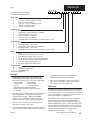
Specifications
Model Number Information
Returns
Warranty
Notes
Technical Assistance
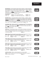
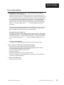
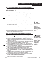
Informational notes alert you to important details. When
you see a note icon, look for an explanation in the margin.
If you encounter a problem with your Watlow control,
review all of your configuration information to verify that
your selections are consistent with your application...
Inputs, Outputs, Alarms, Limits, etc. If the problem persists
after checking the above, you can get technical assistance
by dialing: 1-507-454-5300
or
Safety Information
Boldface safety information protects both you and your
equipment. Please be attentive to them. Here are
explanations:
An Application Engineer will discuss your problem with you.
Please have the following information available:
• Complete model number
• Serial Number
• All configuration information
• User's Manual
The model and serial numbers can be found on the outside
of the case.
The WARNING symbol in the wide text column alerts you
to a "WARNING," a safety hazard which could affect you
and the equipment. A full explanation is in the narrow
column on the outside of the page.
ç
The CAUTION symbol in the wide text column alerts you to
a "CAUTION," a safety or functional hazard which could
affect your equipment or its performance. A full explanation is in the narrow column on the outside of the page.
2
WATLOW Series 945 User's Manual
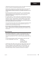
Your Feedback
Your comments or suggestions on this manual are welcome, please send them to: Technical Writer, Watlow
Controls, 1241 Bundy Blvd., P.O. Box 5580, Winona, MN
55987-5580, or phone 507/454-5300. The Watlow Series
945 User's Manual and integral software are copyrighted
by Watlow Winona, Inc., © 1989, with all rights reserved.
blr0392
How to Use the Manual
Chapter 1
Starting Out
Starting Out
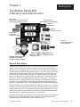
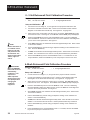
The Watlow Series 945,
A Microprocessor-Based Control
Single Input Type J, K, T, N, R, S, B, C or Pt2
Thermocouple, RTD or Process
Dual Outputs PID or ON/OFF, User Selectable
Output 1 Heat or Cool
Output 2 Heat, Cool or None
Remote Set
Point Input 0-5VDC or 4-20mA
Dual Alarms
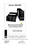
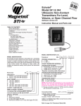
Figure 1 Series 945 Input and
Output Overview
Retransmit Output
(Up to 10 Slaves)
Process
RS-422A, RS423A (RS-232C
compatible), or EIA-485
Optional Computer Interface
Output 1
Auto-tuning
(Heat only)
Set Point
Output 1 or 2
Percent Power
General Description
Welcome to the Watlow Series 945, a 1/4 DIN microprocessor-based temperature
control. It has a single input, remote set point input, dual output, and dual alarm.
The 945 is an auto-tuning control when Output 1 is in the heat mode, and features
Automatic/Manual capability with bumpless transfer. In the Auto mode, the 945 has
closed loop control with sensory feedback, while the Manual mode has open loop
control with user defined output power level. The 945 accepts a variety of thermocouples, as shown above, along with RTD, or process input. The primary output is
heat or cool, while the secondary output can be heat, cool or none. An optional
retransmit output is offered in place of one of the alarms. Selectable as retransmit
of set point or process variable. Units with communications feature data logging
with user selectable table, chart or SPC (Statistical Process Control) printout of data.
With the Series 945 you can select either PID or ON/OFF for Output 1 or 2. Input a
complete set of PID parameters for both outputs, including proportional band, reset/
integral and rate/derivative. By setting either output's proportional band to zero, the
Series 945 becomes a simple ON/OFF control with the switching differential selectable under the HYS (hysteresis) parameter in the Setup menu.
Operator-friendly features include automatic LED indicators to aid in monitoring and
setup, as well as a calibration offset at the front panel. The Watlow Series 945
automatically stores all information in a non-volatile memory.
Getting Started, Chapter 1
WATLOW Series 945 User's Manual
3
Installation
Chapter 2
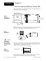
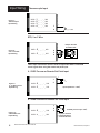
How to Install and Wire the Series 945
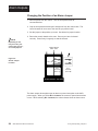
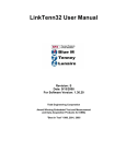
1. Make a panel cutout per the dimensions given below. Your panel thickness can
be from 0.06" to 0.25" (1.52 to 6.35 mm).
3.62" to 3.65" sq.
(92 to 92.25 mm)
Figure 2 Series 945
Panel Cutout and
Unit Dimensions
0.92"
(23 mm)
Panel
Cutout
6.0"
(152 mm)
3.6" ± 0.015"
(90 mm ± 0.381)
3.8" sq.
(97 mm)
3.63" X 3.63"
(92.08 X 92.08 mm)
Bezel
0.17" sq.
Dimension (4 mm)
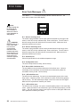
2. Remove the 945 from its case by turning the front panel screw 90° counterclockwise (CCW). Grip the bezel firmly and pull the control out of the case.
Figure 3 How to Open the
Series 945.
!
LOCK
!
CAUTION:
The front panel
screw turns 90°
only. Do not apply
excessive force or
turn the screw more
than 90°.
3. Place the case in the cutout you just made. Attach the two mounting brackets,
shipped with your unit, either to the top and bottom, or to both sides of the unit.
Tighten the brackets securely against your panel.
Panel
Figure 4 Mounting the
Series 945 Case.
Mounting Bracket
4. Insert the control chassis into its case and press the bezel to seat it. Turn the
front panel screw 90° clockwise (CW) to lock the control in place.
4
WATLOW Series 945 User's Manual
Install and Wire, Chapter 2
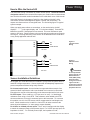
Power Wiring
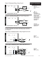
How to Wire the Series 945
The Series 945 wiring is illustrated by model number option. Check the terminal
designation sticker on the control and compare your model number to those shown
here and also the model number breakdown on the inside back cover of this manual.
Series 945 internal circuits appear "inside" the line drawing of the 945, while
connections and terminal designations appear "outside" the line drawing. All
outputs are referenced to a de-energized state. The final wiring figure is a typical
system example.
When you apply power without a sensorinput on the terminal strip, the 945
displays "- - - -" in the upper display, and "0" in the lower display. Press AUTO/
MAN twice, and ER 7 is displayed for one second. This error indicates an open
sensor or A/D error. Remove power to the control and connect the sensor properly,
see Page 6. All wiring and fusing must conform to the National Electric Code and
to any locally applicable codes as well.
Fuse
11
12
13
L1
L2
Figure 5 120 VAC Power
Wiring
Earth Ground
120 VAC
L1
10
Fuses
L2
12
13
Figure 6 240 VAC Power
Wiring
Earth Ground
WARNING:
240 VAC
Sensor Installation Guidelines
We suggest you mount the sensor at a location in your process or system where it
reads an average temperature. Choose a point that will adequately represent the
process temperature without being overly reactive.
For thermocouple inputs: Use an isolated or ungrounded thermocouple if an
external 4-20mA output device with a non-isolated circuit common is connected.
Extension wire must be of the same alloy as the thermocouple itself to limit errors.
To avoid potential
electric shock, use
National Electric
Code (NEC) safety
practices when
wiring and connecting this unit to a
power source and to
electrical sensors or
peripheral devices.
For RTD inputs: There could be a +2°F input error for every 1 of lead length
resistance when using a 2 wire RTD. That resistance, when added to the RTD
element resistance, will result in erroneous input to the instrument. To overcome
this problem, use a 3 wire RTD sensor, which compensates for lead length resistance. When extension wire is used for a 3-wire RTD, all wires must have the
same electrical resistance (i.e. same gauge, copper stranded).
For 0-5VDC or 4-20mA process inputs: The rL and rH settings scale the display
to match the measured range of the process signal. For 0-5VDC process input, the
impedance is 100KΩ. For 4-20mA process input, the impedance is 249Ω.
Install and Wire, Chapter 2
WATLOW Series 945 User's Manual
5
Input Wiring
Figure 7 Thermocouple
Input Wiring
Thermocouple Input
945A - 1 _
945A - 2 _
945A - 3 _
945A - 4 _
_
_
_
_
_ - _ 000
_ - _ 000
_ - _ 000
_ - _ 000
7
9
+
-
(-) = Red
RTD, 2 or 3 Wire
Jumper #5 to #6
for 2 Wire RTD
Figure 8 2 or 3 wire RTD
Input Wiring.
945A - 2 _ _ _ - _ 000
945A - 3 _ _ _ - _ 000
4
4
5
6
5
6
These input connections are also used in conjunction with T/C and RTD
sensor types when using the remote set point input.
0 - 5VDC Process or Remote Set Point Input
+
1
Figure 9 0 - 5 VDC Process
Input Wiring.
945A - 2 _ _ _ - _ 000
VDC
3
Input impedance: 100KΩ
945A - 3 _ _ _ - _ 000
4 - 20mA Process or Remote Set Point Input
945A - 2 _ _ _ - _ 000
Figure 10 4-20mA Process
Input Wiring.
6
945A - 3 _ _ _ - _ 000
WATLOW Series 945 User's Manual
1
2
3
+
IDC
-
4-20mA process input: 249Ω.
A jumper must be
installed between
Terminal #2 and 3.
Install and Wire, Chapter 2
Output 1 Wiring
Output 1 - Solid State Relay With Contact Suppression
945A - _
Figure 11 Solid State Relay
With Contact
Suppression
B _ _ - _ 000
Suppression
17 N.O.
External
Load
18 COM.
L2
L1
Fuse
Off state
state impedance:
impedance: 20K
31MΩmax.
max.
Off
Figure 12 Switched DC
(Open Collector)
Output 1 - Switched DC Output (Open Collector)
NOTE:
Minimum load
resistance is 500 .
Available current is
22mA maximum.
Typical voltage drop
across a 1K load is
12 to 19 volts.
945A - _ C _ _ - _ 000
Switched DC, Open Collector,
Non-Isolated
Logic
Switch
-
16
-
+
17
+
External
Load
Output 1 - Mechanical Relay, 6 Amp, Form C
Figure 13 6 Amp Mechanical
Relay
945A - _ D _ _ - _ 000
Mechanical Relay, Form C, 6 Amp
16 COM.
Fuse
17 N.O.
18 N.C.
Off state impedance: 20KΩ min.
External
Load
NOTE:
This output is
supplied with an arc
suppression snubber
across the output
terminals. High
impedance loads may
remain energized
even though the
output device is
turned OFF.
L1
L2
Output 1 - Process, 4 - 20mA
945A - _ F _ _ - _ 000
Process, 4-20 mA, Non-Isolated
I DC
Figure 14 Process, 4-20mA
+
17
+
-
18
-
External
Load
Load impedance: 600Ω max.
Install and Wire, Chapter 2
WATLOW Series 945 User's Manual
7
Output 1 & 2 Wiring
Output 1 - Process, 0 - 5VDC
945A - _ H _ _ - _ 000
Figure 15 Process, 0 - 5VDC
+
17
+
-
18
-
External
Load
Load impedance: 10KΩ min.
Figure 16 Solid State Relay
Without Contact
Suppression
Output 1 - Solid State Relay Without Contact Suppression
945A - _ K _ _ - _ 000
Solid State Relay, Form A, 0.5 Amp
17 N.O.
External
Load
18 COM.
Figure 17 Solid State Relay
With Contact
Suppression
NOTE:
This output is supplied
with an arc suppression
snubber across the
output terminals. High
impedance loads may
remain energized even
though the output device
is turned OFF.
L2
L1
Fuse
Off state impedance: 31MΩ max.
Output 2 - Solid State Relay With Contact Suppression
945A - _ _ B _ - _ 000
Suppression
14 N.O.
Fuse
L1
15 COM.
L2
External
Load
Off state impedance: 20KΩ max.
NOTE:
Minimum load resistance is 500Ω. Available
current is 22mA
maximum. Typical
voltage drop across a
1KΩ load is 12 to 19
volts.
Output 2 - Switched DC Output (Open Collector)
Switched DC, Open Collector,
945A - _ _ C _ - _ 000
Non-Isolated
Logic
Switch
14
+
15
-
External
Load
Figure 18 Switched DC Output
(Open Collector)
Load impedance: 10KΩ min.
8
WATLOW Series 945 User's Manual
Install and Wire, Chapter 2
Output 2 & Alarms
Output 2 - Mechanical Relay, 6 Amp, Form A
945A - _ _ D _ - _ 000
External
Load
Suppression
14 N.O.
L2
15 COM.
Figure 19 6 Amp Mechanical
Relay
L1
Fuse
Off state impedance: 20KΩ min.
Output 2 - Solid State Relay Without Contact Suppression
945A - _ _ K _ - _ 000
Solid State Relay, Form A, 0.5 Amp
Fuse
14 N.O.
L1
15 COM.
NOTE:
This output is
supplied with an arc
suppression snubber
across the output
terminals. High
impedance loads may
remain energized
even though the
output device is
turned OFF.
L2
External
Load
Figure 20 Solid State Relay
Without Contact
Suppression
Off state impedance: 31MΩ max.
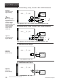
For more information on alarms and alarm jumper selection,
see Chapter 5.
Alarm Output - Mechanical Relay, 6 Amp, Single Form A or B
945A- _ _ _ 1 - _ 000
Figure 21 Alarms
Option 1 Wiring.
Suppression
Fuse
26
L1
Output #3
27
Load
L2
Off state impedance: 20KΩ min.
Alarm Output - Mechanical Relay, 6 Amp, Dual Form A or B
945A- _ _ _
2 - _ 000
Suppression
24
25
Output #4
Fuse
Load
Fuse
26
Output #3
27
L1
L2
Figure 22 Alarms
Option 2 Wiring.
L1
Load
L2
Off state impedance: 20KΩ min.
Install and Wire, Chapter 2
WATLOW Series 945 User's Manual
9
Alarm/Retransmit
Mechanical Relay, 6 Amp, Form A or B/0 - 5VDC Retransmit
Figure 23 Alarm/Retransmit
Option 3 Wiring.
-
945A- _ _ _ 3 - _ 000
External
Load
+
NOTE:
This output is supplied with an arc
suppression snubber
across the output
terminals. High
impedance loads may
remain energized
even though the
output device is
turned OFF.
24
25
26
+
Fuse
27
L1
Load
L2
Load impedance: 10KΩ min. for 0-5VDC. Relay offstate impedance: 20KΩ.
Mechanical Relay, 6 Amp, Form A or B/4 - 20mA Retransmit
945A- _ _ _ 4 - _ 000
-
IDC
Figure 24 Alarm/Retransmit
Option 4 Wiring.
+
External
Load
+
24
25
26
Fuse
L1
27
Load
L2
Load impedance: 10K min. for 4-20mA. Relay offstate impedance: 20K .
0 - 5VDC Retransmit Output
Figure 25 Retransmit
Option 5 Wiring.
Process,
_ 000
945A- _0-5VDC
_ _ 5 - non-isolated
-
24
+
25 +
-
External
Load
Load impedance: 10KΩ min.
4 - 20mA Retransmit Output
945A- _ _ _ 6 - _ 000
Figure 26 Retransmit
Option 6 Wiring.
-
IDC
+
24 25 +
External
Load
Load impedance: 600Ω max.
10
WATLOW Series 945 User's Manual
Install and Wire, Chapter 2
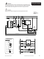
Wiring Example
WARNING:
All wiring and fusing must conform to the National Electric Code NFPA70 and to
any locally applicable codes. Contact your local board for additional information.
Failure to observe NEC safety guidelines could result in injury to personnel.
ç
CAUTION:
Watlow mercury relays are designed to be used only with resistive loads.
Figure 27 System Wiring
Example
L1
120 VAC
L2
Earth Ground
Fuse
140A-16XX-6000
High Limit Control
945A-2DD0-A000
Rear View
11
12
13
(+)
7
(-)
(-) (+)
Ground
16
17
COM
N.O.
Normally Open
Momentary
Switch
9
Mercury
Relay for
Control
Red
High Limit
Mechanical
Contactor
ç
Heater
Coil
Limit Sensor
Process Sensor
945A-2DD0-A000
140A-1601-6000
L1
L2
945A-2DD0-A000
Terminal
Function
1
1
2
3
4
5
6
7
8
9
10
11
12
13
14
15
16
17
18
4-20, 0-5 +
4-20, Jumper to 3
4-20, 0-5 S1
S2
S3
T.C. +
Not Used
T.C. L1 240V
L1 120V
L2
Earth Ground
N.O.
Output #2
Com.
Com.
N.O.
Output #1
N.C.
1
3
4
1
11
3
2
4
(+) 7
5
(-) 9
6
16
2
17
7
1CR
2
Hg
5
6
7
8
9
10
11
1
L1
8
L2
2
9 Reset
Series 140
10
COM
Limit
11 TC (+) Control
12 TC (-)
N.O.
COM
N.C.
13
1
15
2CR
R
2
2
Hi Temp. Light
Hg
12
1
16
17
1CR-1
Install and Wire, Chapter 2
12
Series 945
Temperature
Control
18
Heater
2
2CR-1
WATLOW Series 945 User's Manual
11
Keys/Displays
Chapter 3
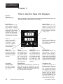
How to Use the Keys and Displays
Figure 28 Series 945
Keys and Displays.
After 1 minute with no key activations, the control reverts to the process value in the
upper display and the set point in the lower display.
Upper Display
Red, 0.56" (14 mm) high,
seven segment, four digit
LED display, indicating
either process actual
temperature, the operating
parameter values, or an
open sensor. When powering up, the Process display
will be blank for 8 seconds.
Lower Display
Red 0.56" (14 mm) high, seven
segment, four digit LED
display, indicating the set
point, operation parameters,
menu parameters, and error
or alarm codes.
L 1 & L2
When lit, these LED's
tell you when Output 1
or Output 2 is energized. L2 only appears
if your unit has the #2
output hardware.
A1 & A2
When lit, these LEDs tell you
when Alarms 1 or 2 are active.
Only appears on those units
with alarms option.
MODE Key
Steps the control
through the Operating
menu; also, in the Auto
mode, enters new data
selected.
UP Key
Increases the value of
the displayed parameter. A single touch increases the value by
one. Hold the key
down to increase the
value at a rapid rate.
New data is self entering in 5 seconds.
Front Panel
Locking Screw
Secures or releases
the control chassis
from its case.
UP/DOWN keys
When pressed simultaneously for 3 seconds, the
Setup Menu appears displaying the LOC
parameter. At the LOC parameter, continue to
press the UP/DOWN keys simultaneously , and
the Calibration Menu will appear.
12
WATLOW Series 945 User's Manual
DOWN Key
Decreases the value of
the displayed parameter. A single touch decreases the value by
one. Hold the key down
to decrease the value
at a rapid rate. New
data is self entering in 5
seconds.
AUTO/MAN Key
Pressed once, it clears any
latched alarms. If the key is
pressed again within 5
seconds, the control toggles
between the Auto and Manual
mode. While in the Manual
mode, percent power is always
displayed in the lower display.
Auto/Manual LED
Lit when the control is in
Manual operation. Press the
key twice to enter Auto operation. A blinking Auto/Manual
LED indicates that pressing
the AUTO/MAN key toggles
between Auto and Manual.
After 5 seconds without pressing the AUTO/MAN key, the
LED stops blinking, and returns to its previous state.
Keys and Displays, Chapter 3
Setup
Chapter 4
How To Setup The Series 945
Setting up the Series 945 is a simple process. First configure the 945's features to
your application in the Setup Menu, and then enter values in the Operating Menu.
Use the MODE key to move through the menus and the UP/DOWN keys to select
data.
At this point, enter the Calibration menu by pressing the UP/DOWN keys simultaneously for 3 seconds. Selecting US or SI under the dFL parameter determines the
following: If selected as US, rate, reset, °F and proportional band in degrees will
appear. If selected as SI, integral, derivative, °C and proportional band in % of span
will appear. See Appendix II to change this parameter.
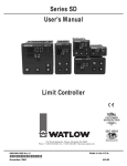
How to Set the DIP Switch
The Watlow Series 945 has a Dual In-line Package (DIP) switch inside the control on
the A007-1954 circuit board (middle board). The location of the board and switches
appear below. The switches are clearly numbered. When Switch #1 is ON, the Setup
parameters can be viewed but not changed. Switch #2 is not used. The factory
default is OFF.
A007-1954
Figure 29 DIP Switch Location
and Orientation
1 Hardware Lockout of
SETUP Parameters
2 Battery
Not Used
Discharge for
Storage
(Factory default is OFF)
Control Chassis - Top View
Entering the Setup Menu
Enter the Setup Menu by pressing the UP/DOWN keys simultaneously for 3 seconds.
The lower display shows the LOC parameter, and the upper display shows its current
level. All keys are inactive until you release both keys. You can reach the LOC
parameter from anywhere.
You will not see all parameters in this menu, depending on the unit's configuration and
model number. After stepping through the menu it returns to the control set point
parameter under the Operation menu.
Figure 30 Entering the
Setup Menu
Setup, Chapter 4
WATLOW Series 945 User's Manual
13
Setup Menu
= Parameter may or may not appear
depending on control configuration.
M
Figure 31 The Setup Menu
NOTE:
The rL and rH
parameters are used
to scale the display
for process inputs,
and/or will scale the
retransmit range for
process output. rL
and rH also limit the
range of the set
point.
[Set Point]
75
LOC
(
)
User lock out
In
(
)
Input type
rSP
(
)
Remote set point
dEC
(
)
Decimal place
C_F
(
)
Celcius_Fahrenheit
rL
(
)
Range low
rH
(
)
Range high
Ot 1
(
)
Output 1
HYS1 (
)
Hysteresis 1
(
)
Output 2
HYS2 (
)
Hysteresis 2
AL 1
(
)
Alarm 1
LAt1
(
)
Latching for alarm 1
HYS3 (
)
Hysteresis 3
Ot4
(
)
Output 4
AL 2
(
)
Alarm 2
LAt2
(
)
Latching for alarm 2
Ot 2
= Only appear if your unit has communications. See the Series 945
data communications manual for more
information on these parameters.
HYS4 (
)
Hysteresis 4
SIL
(
)
Silence alarm
rtd
(
)
RTD calibration curve
bAUd
(
)
Baud rate
dAtA
(
)
Data bits and parity
Prot
(
)
Protocol type
Addr
(
)
Address
Log
(
)
Logging printout
LSL
(
)
Lower spec limit
USL
(
)
Upper spec limit
tbS
(
)
Time base
LinE
(
)
Lines per page
YEAr
(
)
Current year
Mon
(
)
Current month
dAY
(
)
Current day
HOUr
(
)
Real time hour
Min
(
)
Real time minutes
Int
(
)
Time interval
tAg
(
)
Variables to transmit
Setup Parameters
When you are at the top of the menu, the Series 945 displays the user level of
operation in the upper display, and the LOC parameter in the lower display.
Press the MODE key and the value of the next parameter appears in the upper
display, the prompt appears in the lower display. For units with process input, see
the L-r parameter on Page 20 for how LOC is affected.
LOC
Lock: Selects the level of operator lockout. Range: 0 - 3
Default: 0
LOC 0: All operating parameters may be viewed or changed. Manual operation is
permitted. Bumpless transfer to manual operation can occur on sensor break.
LOC 1: The set point, actual, and L-r (if rSP is enabled) are the only visible parameters,
set point is adjustable in this level. Manual operation is permitted. Bumpless
transfer to manual operation can occur on sensor break.
LOC 2: The set point, actual, and L-r (if rSP is enabled) are the only visible parameters,
set point is adjustable in this level. Manual operation is not permitted.
Bumpless transfer is defeated, outputs are disabled on sensor break.
LOC 3: The set point and actual are the only visible parameters, set point is not
adjustable in this level of lockout. Manual operation is not permitted. Bumpless
transfer is defeated, outputs are disabled on sensor break.
14
WATLOW Series 945 User's Manual
Setup, Chapter 4
Setup
Input: Selects the sensor input type. Only those input types which are compatible
with your unit will appear. See the model number information for your type.
Range: J, K (appears as H), t, n, c, r, S, b, Pt2, rtd, rt.d, 0-5, 420
Default: J or r
In
Remote Set Point: Enables models with process input capability to accept a remote
set point signal from another device. This parameter only appears if In = Thermocouple or RTD.
Range: OFF, 0-5, 420
Default: OFF
rSP
Decimal: Selects the location of the decimal point for all process related data. This
parameter only appears if the In parameter is 0-5 or 420.
Range: 0, 0.0, 0.00
Default: 0
dEC
Celsius _ Fahrenheit: Selects the units of temperature measurement. This parameter only appears if the In parameter is a thermocouple or RTD input. Dependent on
the dFL parameter. See Appendix II.
Range: C or F
If dFL = US: Default: C
If dFL = SI: Default: F
C_F
Range Low: Selects the low end of the set point range. See the model number and
specification information on the inside back cover, and Table 1 on Page 16 for sensor
range values. Also used to set the low end of the process or remote set point input
and/or the low end of the range for the retransmit output. 0.0VDC and 4mA represent
Range Low (rL) for process inputs and outputs. The process input and retransmit
output are linearly scaled between rL and rH.
Range: Sensor range low to rH
Default: Low limit of sensor type
Range High: Selects the high end of the set point range. See the model number and
specification information on the inside back cover, and Table 1 on Page 16 for your
sensor range values. Also used to set the high end of the process or remote set point
input and/or the high end of the range for the retransmit output. 5.0 VDC and 20mA
represent Range High (rH) for process input and output. The process input and
retransmit output are linearly scaled between rL and rH.
Range: Sensor range high to rL
Default: High limit of sensor type
rL
rH
Output 1: Selects the output action for the primary output. Action is in response to
the difference between set point and process variable. Select ht (heat) for reverse
acting or select CL (cool) for direct acting. Range: ht, CL
Default: ht
Ot1
Hysteresis 1: Selects the switching hysteresis for Output 1 when Pb1 = 0 (ON/
OFF). See Page 18 for the Pb1 parameter.
Range: 1°F - 99°F
0.1°F - 9.9°F
Default: 3°F/0.3°F
1°C - 55°C
0.1°C - 5.5°C
1 Unit - 99 Units
0.1 Units - 9.9 Units
HYS1
Output 2: Selects the output action for the secondary output. Action in response to
the difference between set point and process variable. Select ht (heat) for reverse
acting or select CL (cool) for direct acting. This parameter only appears if you have a
secondary output. Range: CL, ht, no
Default: CL
Hysteresis 2: Selects the switching hysteresis for Output 2 when Pb2 = 0 (ON/OFF).
See Page 18 for the Pb2 parameter. This parameter only appears if you have a
secondary output; it will not appear if Ot2 = no.
Range: 1°F - 99°F
0.1°F - 9.9°F
Default: 3°F/0.3°F
1°C - 55°C
0.1°C - 5.5°C
1 Unit - 99 Units
0.1 Units - 9.9 Units
Setup, Chapter 4
Ot2
HYS2
WATLOW Series 945 User's Manual
15
Setup
AL1
LAt1
HYS3
Alarm 1: Determines whether the alarm type for Alarm 1 is process, deviation, or
none. A process alarm is set at an absolute temperature. A deviation alarm follows
or tracks the set point. This parameter only appears if your unit has alarms.
Range: Pr, dE, no Default: Pr
Latching 1: Selects whether Alarm 1 is latching or non-latching. Latching alarms
must be cleared before the alarm output will reset. Non-latching automatically resets
the alarm output when the condition clears. This parameter will not appear if AL 1 =
no, or your unit does not have alarms. Range: LAt or nLA Default: nLA
Hysteresis 3: Selects the switching hysteresis for Alarm 1. Appears if
your unit has alarms and AL 1 = Pr or dE.
Range: 1°F - 99°F
0.1°F - 9.9°F
Default: 3°F
1°C - 55°C
0.1°C - 5.5°C
1 Unit - 99 Units
0.1 Unit - 9.9 Units
Ot4
Output 4: Selects Output 4 as retransmit of Process (PrOC) or Set Point (StPt).
Hardware must be present. Scaling of the retransmit output is determined by rL and
rH.
Range: PrOC, StPt, no
Default: PrOC
AL2
Alarm 2: Determines whether Alarm 2 type is process, deviation, or none. A process
alarm is set at an absolute temperature. A deviation alarm follows or tracks the set
point. This only appears if your unit has alarms.
Range: Pr, dE, no
Default: Pr
LAt2
HYS4
SIL
rtd
Latching 2: Selects whether Alarm 2 is latching or non-latching. Latching alarms
must be cleared before the alarm output will reset. Non-latching automatically resets
the alarm output when the condition clears. Will not appear if your unit does not have
alarms or AL2 = no. Range: LAt or nLA Default: nLA
Hysteresis 4: Selects the switching hysteresis for Alarm 2. Appears if
your unit has alarms and AL 2 = Pr or dE.
Range: 1°F - 99°F
0.1°F - 9.9°F
Default: 3°F
1°C - 55°C
0.1°C - 5.5°C
1 Unit - 99 Units
0.1 Unit - 9.9 Units
Silencing: Selects alarm silencing (inhibit) for Alarm 1. This parameter only appears
when AL1 = dE. For more information see Chapter 5.
Range: On or OFF
Default: OFF
RTD: Selects the RTD calibration curve for RTD inputs. Appears if In = rtd or rt.d.
JIS = 0.003916Ω/Ω°C, DIN = 0.003850Ω/Ω°C.
Range: din or JIS
Default: din
Any parameters that appear after RTD are related to data communications. See How
to Use Data Communications with the Watlow Series 945 for more information.
Input Type
Table 1 Input Ranges.
16
J
K (appears as H)
t
n
c
Pt2
r
S
b
rtd (1°)
rt.d (0.1°)
0-5 (VDC)
420 (mA)
WATLOW Series 945 User's Manual
Sensor Range Low
Sensor Range High
32°F/0°C
-328°F/-200°C
-328°F/-200°C
32°F/0°C
797°F/425°C
32°F/0°C
32°F/0°C
32°F/0°C
1598°F/870°C
-328°F/-200°C
-99.9°F/-99.9°C
-5.00/-50.0/-500
-5.00/-50.0/-500
1382°F/750°C
2282°F/1250°C
662°F/350°C
2282°F/1250°C
4200°F/2315°C
2543°F/1395°C
2642°F/1450°C
2642°F/1450°C
3092°F/1700°C
1112°F/600°C
392.0°F/200.0°C
35.00/350.0/3500
35.00/350.0/3500
Setup, Chapter 4
Setup
Setup Menu
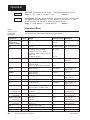
Use this page as a master copy for configuring your Series 945.
Do not enter any values here; make photocopies instead.
Table 2 Setup Menu Prompts
and Descriptions.
Parameter
Range
Factory Default
LOC
0-3
0
In
J, K (appears as H), t, n, c, Pt2,
r, S, b, rtd, rt.d, 0-5, 420
J or r
rSP
OFF, 0-5, 420
OFF
In = T/C or RTD
dEC
0, 0.0, or 0.00
0
In = 0-5 or 420
C_F
C or F
F
In = T/C or RTD
rL
rL to rH
Input dependent.
rH
rH to rL
Input dependent.
Ot1
ht or CL
ht
HYS1
1°F - 99°F, 1°C - 55°C, 1U - 99U
0.1°F - 9.9°F, 0.1°C - 5.5°C, 0.1U - 9.9U
3°F
Ot2
ht, CL or no
CL
Unit has secondary output
HYS2
1°F - 99°F, 1°C - 55°C, 1U - 99U
0.1°F - 9.9°F, 0.1°C - 5.5°C, 0.1U - 9.9U
3°F
Unit has secondary output
Ot2 = ht or CL
AL1
Pr, dE or no
Pr
Unit has alarms
LAt 1
LAt or nLA
nLA
Unit has alarms and
AL1 = Pr or dE
HYS3
1°F - 99°F, 1°C - 55°C, 1U - 99U
0.1°F - 9.9°F, 0.1°C - 5.5°C, 0.1U - 9.9U
3°F
Unit has alarms and
AL1 = Pr or dE
Ot4
no, PrOC, StPt
PrOC
Hardware is present
AL 2
Pr, dE or no
Pr
Unit has alarms
LAt 2
LAt or nLA
nLA
Unit has alarms and
AL2 = Pr or dE
HYS4
1°F - 99°F, 1°C - 55°C, 1U - 99U
0.1°F - 9.9°F, 0.1°C - 5.5°C, 0.1U - 9.9U
3°F
Unit has alarms and
AL2 = Pr or dE
SIL
On or OFF
OFF
Unit has alarms & AL1 = dE
rtd
JIS or din
din
In = rtd or rt.d
Setup, Chapter 4
Value
Appears If:
WATLOW Series 945 User's Manual
17
Operation
Operation Menu
In the Operation menu, the 945 operates as a digital set point control. All outputs
are turned OFF when set point is set to OFF.
= Parameter may not appear
depending on control configuration
NOTE:
= Only appears if your unit has communications.
See the Series 945 data communications
manual for more information.
The upper display will
always return to the
process value after 1
minute without key
strokes.
M
75
Figure 32 The Operation Menu
Mode Key
[Control Set Point or
Remote Set Point ]
Ct1
(
)
Ct2
(
)
Cycle time 1
Cycle time 2
SP2
(
)
Set point 2
db
(
)
Dead band
Pb1
(
)
A1LO
(
)
Alarm 1low
Pb2
(
)
Proportional band 1
Proportional band 2
A1HI
(
)
Alarm 1 high
rE1/It1 (
)
Reset 1/Integral 1
A2LO
(
)
Alarm 2 low
rE2/It2 (
)
Reset 2/Integral 2
A2HI
(
)
Alarm 2 high
rA1/dE1 (
)
CAL
(
)
Calibration offset
rA2dE2 (
)
Rate 1/Derivative 1
Rate 2/Derivative 2
AUt
(
)
Auto-tune
CLUP
(
)
Control limit update
L-r
(
)
Local-remote
Operation Parameters
75
Set Point 1 or Remote Set Point 1: Sets the operating set point for the control
outputs. Appears if L-r = L, see Page 20. If L-r = R, this parameter represents the
remote set point. Range: OFF / rL to rH
Default: Dependent on input range
SP2
Set Point 2: Sets the operating set point for Output 2 when control mode is ht/ht or
CL/CL. Appears when Ot1 and Ot2 are the same, and functions as an ON/OFF
control. Range: rL to rH
Default: Same as primary set point.
Pb1
Proportional Band: Expressed in degrees, process units or % of span, within which
a controller proportioning function is active for Output 1 or 2. When PbX = 0, it
functions as an ON/OFF control. The switching differential is then determined by the
corresponding HYSX parameter. Pb1 is always visible. Pb2 will not appear if your unit
does not have Output 2, Ot2 = no, or Ot2 is the same value as Ot1. Also dependant
on the dFL parameter in the Calibration menu.
If dFL = US: Range: 0 to 999°F/0 to 555°C/0 to 999 Units; 0.0 to 9.9°F/0.0 to 5.5°C/
0.0 to 9.9 Units Defaults: Pb1 = 25°F/2.5°F
Pb2 = 0
If dFL = SI: Range: 0 to 999.9% of span Defaults: Pb1 = 3.0%
Pb2 = 0.0%
Pb2
18
WATLOW Series 945 User's Manual
Setup, Chapter 4
Operation
Reset/Integral1: A reset (integral) control action for Output 1 or Output 2 automatically eliminating offset, or "droop," between set point and actual process temperature.
Will not appear if your unit does not have a secondary output.
rE1/It1: Will not
appear if Pb1 = 0. rE2/It2: Will not appear if Pb2 = 0, Ot2 = no, or Ot2 is the same
configuration as Ot1. Either reset (rE) or integral (It) will appear depending on how the
dFL parameter is set in the Calibration menu.
See Appendix II.
If dFL = US:
Range: 0.00 to 9.99 repeats/minute
Default: 0.00
If dFL = SI:
Range: 00.1 to 99.9 minutes per repeat
Default: 0.00
Rate/Derivative 1: The rate (derivative) function for Output 1 or Output 2. Rate or
derivative is used to eliminate over shoot on start up, or after the set point changes.
rA1/dE1: Will not appear if Pb 1 = 0. rA2/dE2: Will not appear if your unit does not
have a secondary output, Pb2 = 0, Ot2 = no, or Ot2 is the same value as Ot1. Either
rate (rA) or derivative (dE) will appear depending on how dFL is set in the Calibration
menu. If dFL = US or SI: Range: 0.00 to 9.99 minutes Default: 0.00
Cycle Time 1 & 2: Time for a controller to complete one ON/OFF cycle for Output
1or Output 2; expressed in seconds. Ct1: Will not appear if Pb 1 = 0, or Output 1 is 420mA. Ct2: Will not appear if your unit does not have a secondary output, Pb2 = 0,
Ot2 = no, or Ot2 is the same value as Ot1.
Range: 1 to 60 seconds
Default: 5
Dead Band: The area between Output 1 and 2 where no heating or cooling takes
place in a heat/cool proportional control. Only appears if your unit is set up as a ht/CL
or CL/ht unit. Range: ±0 to 99°F/0 to 55°C/0 to 99 Units; or ±0.0 to 9.9°F/0.0 to
5.5°C/0.0 to 9.9 Units
Default: 0
Alarm 1 Low: Represents the low process alarm or low deviation alarm for Alarm 1.
Will not appear if your unit does not have alarms and AL 1 = no.
If AL 1 = dE:
Range: 0 to -999°F/0 to -999°C/0 to -999 Units Default: -999°F
If AL 1 = Pr:
Range: rL to A1HI
Default: rL
rE1/It1
rE2/It2
rA1/dE1
rA2/dE2
Ct1
Ct2
db
A1LO
Alarm 1 High: Represents the high process alarm or high deviation alarm for Alarm
1. Will not appear if your unit does not have alarms and AL 1 = no.
If AL 1 = dE:
Range: 0 to 999°F/0 to 999°C/0 to 999 Units
Default: 999°F
If AL 1 = Pr:
Range: A1LO to rH
Default: rH
A1HI
Alarm 2 Low: Represents the low process alarm or low deviation alarm for Alarm 2.
Will not appear if your unit does not have Alarm 2 and AL 2 = no.
If AL 2 = dE:
Range: 0 to -999°F/0 to -999°C/0 to -999 Units Default: -999°F
If AL 2 = Pr:
Range: rL to A2HI
Default: rL
A2LO
Alarm 2 High: Represents the high process alarm or high deviation alarm for Alarm
2. Will not appear if your unit does not have Alarm 2 and AL 2 = no .
If AL 2 = dE:
Range: 0 to 999°F/0 to 999°C/0 to 999 Units
Default: 999°F
If AL 2 = Pr:
Range: A2LO to rH
Default: rH
Calibration Offset: Adds or subtracts degrees from the input signal.
Range: -180°F to 180°F/-100°C to 100°C/-180Units to 180 Units; or -180.0°F to
180.0°F/-100.0°C to 100.0°C
Default: 0
Setup, Chapter 4
A2HI
CAL
WATLOW Series 945 User's Manual
19
Operation
AUt
L-r
Table 3 Operation Menu
Prompts and
Descriptions.
Parameters
Auto-Tune: Initiates auto-tune for Output 1. This parameter appears if Ot 1 =ht.
Range: 0 = off, 1 = slow, 2 = medium, 3 = fast
Default: 0
Local-Remote: Selects a local or remote set point for the Series 945. This parameter
only appears if the LOC parameter = 0, 1 or 2, and rSP = 0-5 or 420. If L-r = r, the
remote set point will be displayed in place of the internal set point.
Range: L = Local operation r = remote operation
Default: L
Operation Menu
Use this page as a master copy for your Series 945 Operation parameters.
Do not enter any values here; make photocopies instead.
Value
Range
Set Point 1 or
Remote Set Point 1
SP2
rL to rH
Pb1
If dFL = US:
0 - 999°F/0 - 555°C/0 - 999U
0 - 99.9°F/0 - 55.5°C/0 - 99.9U
0=ON/OFF control. HYS1 =swtch. diff.
If dFL = SI:
0 to 999.9% of span
Factory Default
Appears If:
rL to rH
75°F
Primary set point.
Ot1 = Ot2, Pb1 = 0
25°F/2.5°F
3%/.3%
Pb2
Same as Pb1.
0°F
Ot2 = ht or CL
Ot2 ≠ Ot1
rE1/It1
If dFL = US: 0.00 to 9.99 repeats/min.
0.00 = No Reset.
If dFL = SI: 00.1 to 99.9 min./repeat
0.00 rpt/min.
Pb1 ≠ 0
rE2/It2
Same as rE1/It1.
0.00 rpt/min.
Pb2 ≠ 0, Ot2 ≠ Ot1
Ot2 = ht or CL
rA1/dE1
0.00 to 9.99 min.
0.00 = No Rate.
0.00 min.
Pb1 ≠ 0
rA2/dE2
Same as rA1/dE1.
0.00 min.
Pb2 ≠ 0, Ot2 ≠ Ot1
Ot2 = ht or CL
Ct1
1 to 60 seconds
5 seconds
Pb1 ≠ 0, Output1 ≠ 420
Ct2
1 to 60 seconds
5 seconds
Pb2 ≠ 0, Ot2 ≠ Ot1,
Ot2 = ht or CL
db
±0 - 99°F/±0 - 55°C/0 - 99U.
±0.0 - 9.9°F/0.0 - 5.5°C/0.0 - 9.9U
0
Ht/CL or CL/Ht
A1LO Deviation dE
Process Pr
-999° to 0°
rL to A1HI
-999°
rL
AL1 = Pr, dE
Unit has alarms
A1HI
Deviation dE
Process Pr
0° to 999°
A1LO to rH
999°
rH
AL1 = Pr, dE
Unit has alarms
A2LO Deviation dE
Process Pr
-999° to 0°
rL to A2HI
-999
rL
AL2 = Pr, dE
Unit has Alarm 2
A2HI
0° to 999°
A2LO to rH
999°
rH
AL2 = Pr, dE
Unit has Alarm 2
CAL
±180°F/±100°C/±180U
0
AUt
0-3
0
Ot1 = ht, L-r = L
L-r
L or r
L
rsP = 0-5 or 420
20
Deviation dE
Process Pr
WATLOW Series 945 User's Manual
0.00
Setup, Chapter 4
Tuning
Chapter 5
How to Tune and Operate
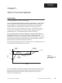
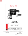
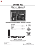
Auto-tuning
Auto-tuning applies to Output 1, heating only.
The auto-tuning procedure operates on a thermal response value — slow, medium,
or fast. Use the slow thermal response when your process does not reach set
point too rapidly, or if it usually does not exceed set point a lot. A fast thermal
response produces a rapid temperature change over a short period of time.
Once the auto-tune sequence has begun, the Output 1 heat proportional band is
set to 0 and the control goes into an ON/OFF mode of control at 90% of the
established set point. The displayed set point remains unchanged.
The cool output remains off for the tuning duration. Once the control learns the
thermal system response, it returns to a standard PID control using the PID values
automatically set as a result of auto-tuning. Output 2 cool PID values are
unaffected by auto-tuning, and remain at their factory default settings. See Manual
tuning on the next page to set cool PID parameters. Any change of the set point,
while in auto-tune, re-initiates the auto-tune procedure.
The Series 945 will not Auto-tune while in remote set point. Transferring from local
to remote set point takes the 945 out of auto-tune.
Auto-tune
Begins
Auto-tune
Complete
Set Point
200
°Temp
180
Process
100
Figure 33 Auto-tuning at a Set
Point of 200°F.
90% of
Set Point
°Time
In order for the 945 to successfully complete auto-tune, the process must cross set
point four times within 80 minutes after auto-tune has started. If this does not
happen within the 80 minute time limit, the Pb remains at 0 and the control
functions in an ON/OFF mode.
Tuning and Operating, Chapter 5
WATLOW Series 945 User's Manual
21
Tuning
To start auto-tuning:
1. Press the MODE key until the AUt parameter appears in the data display.
2.
Select a thermal response value using the UP/DOWN keys, 1=slow,
2=medium, and 3=fast. A thermal response value of 2 satisfactorily tunes
most thermal systems.
3.
Press the MODE key. While the control is in the tuning mode, the lower
display alternately displays the normal information and the prompt At. The
time between alternations is 1 second.
4.
When tuning is complete, the displays return to their previous state and AUt
reverts to 0. The 945 installed appropriate PID tuning parameters and saved
them in the non-volatile memory. If a mechanical relay or contactor is
switching power to the load, a longer cycle time may be desirable to
minimize wear on the mechanical components. Typical life of a
mechanical relay is 100,000 cycles.
To abort auto-tuning, the operator must reset the AUt parameter to 0, press
AUTO/MAN twice, or cycle power off and on. In all cases, aborting auto-tune
restores all values to those previous to auto-tuning.
Manual Tuning
For optimum control performance, tune the Series 945 to your thermal system.
The tuning settings here are for a broad spectrum of applications; your system may
have somewhat different requirements. NOTE: This is a slow procedure, taking
from minutes to hours to obtain optimum value.
NOTE:
Tune heating outputs at a set point above ambient temperature.
Tune cooling outputs at a set point below ambient temperature.
1. Apply power to the Series 945 and enter a set point. Begin with these
Operation parameters: Pb = 1, rE/It = 0.00, rA/dE = 0.00, Ct = 5, CAL = 0,
AUt= 0.
2. Proportional Band Adjustment : Gradually increase Pb until the upper
display temperature stabilizes to a constant value. The process temperature
may not be right on set point because the initial reset value is 0.00 repeats per
minute.
3. Reset/Integral Adjustment: Gradually increase rE/It until the upper display
temperature begins to oscillate or "hunt." Then slowly decrease rE/It until the
upper display stabilizes again near set point.
4. Cycle Time Adjustment: Set Ct as required. Faster cycle times sometimes
achieve the best system control. However, if a mechanical contactor or
solenoid is switching power to the load, a longer cycle time may be desirable to
minimize wear on the mechanical components. Experiment until the cycle time
is consistent with the quality of control you want. Ct will not appear on units
with a process output.
22
WATLOW Series 945 User's Manual
Tuning and Operating, Chapter 5
Tuning/Operation
5. Rate/Derivative Adjustment: Increase rA/dE to 1.00 minute. Raise set point
by 20° to 30°F, or 11° to 17°C, observe the system's approach to set point. If
the load temperature overshoots set point, increase rA/dE to 2.00 minutes.
Next raise set point by 20 to 30°F, or 11 to 17°C and watch the approach to the
new set point. If you increase rA/dE too much, approach to set point will be
very sluggish. Repeat as necessary until the system rises to the new set point
without overshooting or approaching the set point too slowly.
6. Calibration Offset Adjustment: You may want your system to control to a
temperature other than the value coming from the input sensor. If so, measure
the difference between that temperature (perhaps at another point in the
system) and the process value showing in the upper display. Then enter the
CAL offset value you want. Calibration offset adds or subtracts degrees from
the value of the input signal.
Manual and Automatic Operation
To change from manual to auto operation, press AUTO/MAN twice.
Manual operation provides open loop control of the outputs from a range of -100%
(full cooling) to 100% (full heating) power. The 945 allows a negative output value
only with a Cl (Cool) selection on either Ot1 or Ot2. Automatic operation provides
closed loop ON/OFF or PID control. When the operator transfers from a closed
loop to an open loop, the 945 retains the power level from the closed loop control,
referred to as bumpless transfer. When the 945 returns to closed loop control, it
restores the previous set point temperature.
The LED on the AUTO/MAN key indicates auto or manual operation. When the
LED is ON, the control is in manual operation. When the LED is OFF, it is in
Automatic operation. When the LED flashes, press the key again within five
seconds to complete the change in operation.
When a sensor opens the 945 will switch from automatic to manual operation.
•
If LOC = 0 or 1 and the conditions for bumpless transfer are met, process
stabilizes within ± 5% of set point within the last two minutes and less than 75%
power. The 945 switches to manual operation at the last automatic power
level.
•
If LOC = 2 or 3, or the conditions of bumpless transfer have not been met, the
945 switches into manual operation at 0% power (outputs disabled).
When transferring from auto to manual operation, the control output(s) remains
stable ("bumpless," smooth transition). When transferring from manual to
automatic operation, the control output(s) may change significantly. In manual
operation, the output value appears in the lower display; in automatic operation, the
set point appears.
Tuning and Operating, Chapter 5
WATLOW Series 945 User's Manual
23
Alarm Outputs
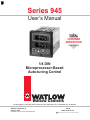
Changing the Position of an Alarm Jumper
1. Remove power from the control. Turn the front panel screw 90°
counterclockwise.
2. Grip the front panel bezel and pull it straight out from the control case. The
control chassis will come out of the case as you pull the bezel.
3. Set the jumper to the position you want. See below for jumper location.
4. Return the control chassis to the case. Be sure you have it oriented
correctly. Press firmly, but gently, to seat the chassis.
NOTE:
Depending on the
unit you order, your
control may have 0, 1,
or 2 alarm jumpers.
Options Board
A007-1954
AL1
Figure 34 Alarms Jumper
Location.
A007-1828 AL2
N.O.
Contacts
(Form A)
N.C.
Contacts
(Form B)
Control Chassis - Top View
The alarm output de-energizes upon an alarm or power interruption to the 945's
power supply. When you select N.O. Contacts, the contact is open when an alarm
occurs. When selecting N.C. Contacts, the contact closes when an alarm occurs.
24
WATLOW Series 945 User's Manual
Tuning and Operating, Chapter 5
Alarms
Using Alarms
The Series 945 has two alarm types, Process or Deviation. A Process alarm sets
an absolute temperature. When the process exceeds that absolute temperature
limit an alarm occurs. The Process alarm set points may be independently set high
and low.
A Deviation alarm alerts the operator when the process strays too far from set
point. The operator can enter independent high and low alarm settings. The
reference for the deviation alarm is the set point. Any change in set point causes a
corresponding shift in the deviation alarm. Example: If your set point is 100°F,
and a deviation alarm set at +7°F as the high limit, and -5°F as the low limit, the
high alarm trips at 107°F, and the low alarm at 95°F. If you change the set point to
130°F, the alarms follow the set point and trip at 137°F and 125°F.
Both process and deviation alarms can be latching or non-latching. When the
alarm condition is removed a non-latching alarm automatically clears the alarm
output. You must manually clear a latching alarm before it will disappear.
Flashing 'LO" or "HI" in the lower display indicates an alarm. The lower display
alternately shows information from the current parameter and the "LO" or "HI"
alarm message at one second intervals. The alarm output is de-energized and the
A1 or A2 LED is lit.
To clear an alarm…
• First correct the alarm condition, then…
• If the alarm is latching…
Clear it manually; press AUTO/MAN once as soon as the process temperature
is inside the alarm limit according to the HYSX parameter.
• If the alarm is non-latching…
The alarm will clear itself automatically as soon as the process
temperature is inside the alarm limit according to the HYSX parameter.
Press once Clear
a latched
and
corrected
alarm.
Figure 35 Alarm Display
Examples
Alarm Silencing for alarm output A1 is available with the deviation alarm. This
overrides alarm A1 during power up. The non-latching mode automatically
enables alarm output A1 on initial power up. In the latching mode, manually
disable the alarm by pressing AUTO/MAN once. In both cases alarm silencing
disables the A1 alarm output relay, but the A1 LED displays the alarm condition
until the process value is within the "safe" region of the deviation alarm band.
Once the process value crosses into the "safe" region, both a latching or a nonlatching alarm is ready. Any future deviation outside this safe band triggers an
alarm.
Tuning and Operating, Chapter 5
WATLOW Series 945 User's Manual
25
Error Codes
Error Code Messages
ç
Four dashes, "- - - -", in the upper display indicate a Series 945 error. The
error code is visible in the lower display.
NOTE:
An alarm display will
be masked by an
error condition or
when the control is
in the Calibration or
Setup Menus.
ç
WARNING:
Electrical noise or a
noise event, vibration or excess
environmental
moisture or temperature may cause
Series 945 errors to
occur. If the cause
of an error is not
otherwise apparent,
check for these.
Er 1 - Sensor overrange error
The sensor input generated a value higher than that allowed for the range of the
sensor, or the A/D circuitry malfunctioned. Enter a valid input. The A/D value is
above the range limits, but within the A/D conversion limits. Make sure the In
parameter matches your sensor.
Er 2 - Sensor underrange error
The sensor input generated a value lower than that allowed for the range of the
sensor, or the A/D circuitry malfunctioned. Enter a valid input. The A/D value is
below the range limits, but within the A/D conversion limits. Make sure the In
parameter matches your sensor.
Er 3 - Ambient error
Check the specification for the ambient temperature range.
Er 4 - Configuration error
The unit's microprocessor is faulty; call the factory.
Er 5 - Non volatile checksum error
The nonvolatile memory checksum discovered a checksum error. Unless a
momentary power interruption occurred while the unit was storing data, the
nonvolatile memory is bad. Call the factory.
Er 6 - A/D underflow error
The A/D circuit is underrange. An open or reversed polarity sensor is the most
likely cause. Check the sensor; if the connection is good, and functions properly,
call the factory. The A/D underrange voltage is too low to convert an A/D signal.
Make sure the In parameter matches your sensor.
Er 7 - A/D overflow error
The A/D circuit is overrange. An open or reversed polarity sensor is the most likely
cause. Check the sensor; if the connection is good, and functions properly, call the
factory. The A/D overrange voltage is too high to convert an A/D signal. Make sure
the In parameter matches your sensor.
26
WATLOW Series 945 User's Manual
Tuning and Operating, Chapter 5
Error Codes
Error Code Actions
• Error codes Er 1, Er 2, Er 3, Er 6, or Er 7 will result in these conditions:
• If operator access is LOC 0 or 1…
…and the control was in AUTO operation when the error occurred, it goes into
manual (% power) operation. If the output power is less than 75% power, and
a <5% change in power occurred within the last two minutes, the 945 switches
into manual operation at the last automatic power level (bumpless transfer). If
the control was in manual operation, it remains there. (Press AUTO/MAN
twice to see the error code.) The alarm output (if present) is in its alarm state
(LED lit). The upper display reads "- - - -". The lower display indicates the
error code.
If the control was operating with stable output values when the error occurred,
it continues to operate at those levels on a % power basis. If output values
were not stable, the control outputs go to 0% power (OFF).
• If operator access is LOC 2 or 3…
The control remains in AUTO operation and the outputs go OFF. AUTO/MAN
and MODE are inactive. The UP/DOWN keys may be used simultaneously to
enter the Setup Menu. The alarm output (if present) is in its alarm state (LED
lit). The Upper display reads "- - - -". The Lower display indicates the error
code.
• To clear a corrected error…
• Cycle power or MODE through Setup until you return to the set point.
• Error codes Er 4 or Er 5 will result in these conditons:
• The control is in AUTO operation with both outputs OFF.
• The alarm outputs are in their alarm state (de-energized with the LED lit).
• The upper display indicates the process value.
• The lower display indicates the error code.
• All keys are inactive.
• All Setup Menu parameters return to default values.
• The above conditions occur regardless of the LOC value, or the presence of
the Setup or Calibration Menus.
• To clear a corrected error…
• Cycle power to the control.
Tuning and Operating, Chapter 5
WATLOW Series 945 User's Manual
27
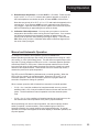
Noise Guidelines
Appendix 1
Noise and Installation Guidelines
For wiring guidelines, refer to the IEEE Standard No. 518-1982, available from
IEEE, Inc. 345 East 47th Street, New York, NY 10017.
Noise Sources
• Switches and relay contacts operating inductive loads such as motors, coils,
solenoids, and relays, etc.
• Thyristors or other semiconductor devices which are not zero crossover-fired
(randomly-fired or phase angle-fired devices).
• All welding machinery and heavy current carrying conductors.
• Fluorescent and neon lights.
Decreasing Noise Sensitivity
• Physical separation and wire routing must be given careful consideration in
planning the system layout. For example, A.C. power supply lines should be
bundled together and physically kept separate from input signal lines (sensor
lines). A 12" (305 mm) minimum separation is usually effective. Keep all
switched output signal lines (high power level) separate from input signal
lines (sensor lines). Cross other wiring at 90° angles whenever crossing is
unavoidable.
• Look at the system layout; identify and locate electrical noise sources such as
solenoids, relay contacts, motors, etc. Route the wire bundles and cables as
far away as possible from these noise sources. Don't mount relays or
switching devices close to a microprocessor control. Don't have phase anglefired devices in the same electrical enclosure or on the same power line with
the control.
• Shielded cables should be used for all low power signal lines to protect from
magnetic and electrostatic coupling of noise. Some simple pointers are:
◊ Run low level signal lines unbroken from signal source to the control circuit.
◊ Connect a shield to the control circuit common at the control end only.
Never leave shields unconnected at both ends or connect both shield ends
to a common ground.
◊ Maintain shield continuity at daisy chain connection points by reconnecting
the broken shield.
◊ Assume no electrostatic shielding when using the shield as a signal return.
If you must, use triaxial cable (electrostatically shielded coaxial cable).
28
WATLOW Series 945 User's Manual
Appendix
Noise
• Twisted pair wire should be used any time control circuit signals must travel over
two feet, or when they are bundled in parallel with other wires.
• Select the size or gauge of wire by calculating the maximum circuit current and
choose the gauge meeting that requirement. Using larger wire sizes than
required generally increases the likelihood of electrostatic (capacitance) coupling
of noise.
• Eliminate ground loops in the entire control system. You can spot the obvious
loops by studying the "as-built" wiring diagram. There are also not-so-obvious
ground loops resulting from connecting internal circuit commons in the
manufacturer's equipment.
• Do not daisy chain A.C. power (or return) lines, or output signal (or return) lines
to multiple control circuits. Use a direct line from the power source to each input
requiring A.C. power. Avoid paralleling L1 (power lead) and L2 (return lead) to
load power solenoids, contactors, and control circuits. If an application uses L1
(power lead) to switch a load, L2 (return lead) has the same switched signal and
could couple unwanted noise into a control circuit.
• Tie all ground terminals together with one lead (usually green wire) tied to ground
at one point. Don't connect ground to the control case if the control is in a
grounded enclosure (preventing ground loops).
• Do not confuse chassis grounds (safety ground) with control circuit commons or
with A.C. supply L2 (return or neutral line). Each return system wiring must be
separate. Absolutely never use chassis ground (safety) as a conductor to return
circuit current.
Eliminating Noise
• Use "snubbers" ("QUENCHARC™") to filter out noise generated by relays, relay
contacts, solenoids, motors, etc. A snubber is a simple filter device using a
0.1µf, 600 volt, non-polarized capacitor in series with a 100 , 1/2 watt resistor.
The device can be used on A.C. or D.C. circuits to effectively dampen noise at its
source.
• The general purpose Watlow snubber, described above, is 0804-0147-0000.
For other "QUENCHARC" sizes contact:
PAKTRON
P.O. Box 5439
Lynchburg, VA 24502
Phone: 804/239-6941
• A Metal Oxide Varistor (MOV) can be used to limit voltage "spikes" that occur on
the A.C. supply lines as a result of lightning strikes, switching large motors, etc.
The MOV is available in several varieties and for 115 or 230 volt lines. The
device dissipates the voltage "spikes" to ground and in doing so repeatedly,
deteriorates its ability to function. MOVs have a limited life. See Table 4.
Appendix
WATLOW Series 945 User's Manual
29
Wiring Guide
• "Islatrols" and other similar power line filters are designed to carry the power for
the control circuit and "buffer" the control circuit from A.C. line noise. Devices
like the Islatrol use media (electromagnetic filtering) other than electric circuits to
filter out electrical noise. Take care in matching the power capabilities of the filter
with power demands of the circuit. Keep line filters as close to the control as
possible to minimize the area for interference pick up.
• Islatrols are available from:
I - 101 (1A, 120VAC)
I - 202 (2.5A, 208/240VAC)
Control Concepts Corporation
328 Water Street
P.O. Box 1380
Binghamton, NY 13902-1380
Phone: 607/724-2484
I - 105 (5A, 120VAC)
I - 207 (7.5A, 208/240VAC)
I - 115 (15A, 120VAC)
• The ultimate protection is an "uninterruptable" power supply. This "senses" the
A.C. power line; when the line fluctuates, a battery powered 60Hz inverted circuit
takes over, supplying power within one-half to one cycle of the A.C. line; very
expensive.
Checking for Ground Loops
To check for ground loops, disconnect the ground wire at the ground termination.
Measure the resistance from the wire to the point where it was connected. The
ohmmeter should read a high ohm value. If you have a low ohm value across this
gap, there is at least one ground loop present in your system.
Or check for continuity; your reading should be "open." If you do find continuity,
begin looking for the ground loops. Begin disconnecting ground in the system one
at a time, checking for continuity after each disconnection. When continuity reads
"open" you have eliminated the ground loop(s). Also, as you reconnect grounds,
keep making the continuity test. It is possible to reconnect a ground loop.
Noise Suppression Devices Available From Watlow
Watlow Controls stocks a few key noise suppression parts. You may order these
by calling your local Watlow distributor.
Item
Table 4 Noise Suppression
Device Ratings
30
Electrical Ratings
Part Number
Common Mode Line Filter
250V, 3 Amp
0804-0196-0000
Differential Mode Line Filter
Refer to the Islatrol listing above.
Metal Oxide Varistor
150V, 80 Joule
0802-0273-0000
MOV
130V, 38 Joule
0802-0304-0000
MOV
275V, 75 Joule
0802-0266-0000
MOV
275V, 140 Joule
0802-0405-0000
Quencharc
0.01µf, 100 , 600VAC
0804-0147-0000
WATLOW Series 945 User's Manual
Appendix
Noise Guidelines
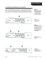
Line Filtering Configurations For Controls
These three diagrams show filter configurations for removing input power noise.
Choose the one best suited for your system. For very dirty or critical applications use a microcomputer-regulated power supply or Uninterruptable Power Supply
(U.P.S.). Don't fasten common mode line filters or filters with metal cases to metal
at ground potential. This prevents ground loops and maintains filter effectiveness.
1 NOTE:
Keep filters 12" (305
mm) or less from the
control. Minimize the
line distance where
noise can be reintroduced to the control.
1
Figure 37 Differential Mode
Filter Wiring
2
2 NOTE:
To prevent ground loops
do not fasten common
mode line filters or filters
with metal that is at
ground potential. Doing
so will reduce filter
effectiveness.
1
Figure 38 Common Mode Filter
Wiring
2
Line
Appendix
Load
1
Figure 39 Combination
Differential/Common
Mode Filter Wiring
WATLOW Series 945 User's Manual
31
Calibration
Appendix 2
Calibration
Before attempting to calibrate, make sure you have the proper
equipment called for in each procedure.
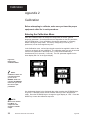
Entering the Calibration Menu
Enter the Calibration Menu to change the configuration of the dFL (default
language) parameter. Several parameters are dependent on the dFL parameter,
they are listed below. It is a good idea to change this parameter, if necessary,
before entering the Setup menu. The factory configures your unit to your
preference, but can be changed at any time.
In the Calibration menu, various input signals must also be supplied in order for the
control to go through its auto calibration. The calibration menu can only be entered
from the LOC parameter in the Setup menu. Press the UP/DOWN keys
simultaneously for 3 seconds (± 1 second). The CAL parameter appears in the
lower display with "no" in the upper display.
Figure 40 Entering the
Calibration Menu.
NOTE:
Calibration values are
not retained unless
you are in the
MANUAL mode. Do
not enter the MANUAL
mode until you are at
the correct input
parameters.
Any inadvertent change in the displayed data, when pressing the UP/DOWN keys,
is ignored. Calibration values are not retained unless you are in the MANUAL
mode. Press the UP/DOWN keys to change the upper display to “YES.” Press the
MODE key to enter the calibration sequence.
NOTE:
While in the Calibration Menu, all
outputs are OFF,
except the 4-20mA
output.
32
WATLOW Series 945 User's Manual
Appendix
Calibration
Upon entering the calibration menu, the top display window indicates CAL. The
upper display continues to indicate CAL (with the exception of calibration of the 420mA output) while the operator walks through the entire calibration parameter list.
While calibrating the 4-20mA output, the upper display contains a numeric value to
be slewed up or down until the output value is correct. The control uses the lower
display to prompt the user as to what the input should be.
The dFL parameter allows you to select either U.S. parameters which include
displaying rate, reset, °F, and proportional band in degrees or units, or select SI
(System International). The parameters displayed here are integral, derivative, °C,
and proportional band in % of span.
Once the information has been properly established and maintained for 5 to 10
seconds, the MODE key may then be used to display the next parameter. After the
final input is established, press the MODE key twice to return the unit to the
configuration menu at the top of the parameter list.
Restoring Factory Calibration
The rSt parameter restores the factory calibration values to the Series 945. If you
calibrate your control incorrectly, you have the option to default to the original
values. Once you leave the CAL menu, the values are entered.
1. Press the UP/DOWN keys simultaneously for three seconds. The LOC
parameter appears in the lower display. Continue holding the UP/DOWN keys
until the lower display reads CAL.
2. Press the UP key until YES appears in the upper display.
3. MODE through the calibration menu until rSt appears in the lower display.
4. Press the UP key until YES appears in the upper display.
5. Press the MODE key and the 945 advances to test the displays.
This procedure is used only to restore calibration, it is not meant to clear
values.
Appendix
WATLOW Series 945 User's Manual
33
Calibration
Calibration Menu
(
)
YES to calibrate, No skips to display test.
tCL
(
)
Input 0.00mV for low thermocouple input.
tCH
(
)
Input 50.00mV (16.035 for r, S or b units) for high thermocouple input.
tC
(
)
Connect a "J" T/C compensator, with inputs shorted. T/C units only.
rLO
(
)
Connect the JIS RTD low resistance per model number.
rHI
(
)
Connect the JIS RTD high resistance per model number.
O U
(
)
Set the voltage source to 0.000 volts.
5 U
(
)
Set the voltage source to 5.000 volts.
4 A
(
)
Set the current source to 4.00mA.
20A
(
)
Set the current source to 20.00mA.
O1LO (
)
Press the UP/DOWN keys until Output 1 reads process low.
O1HI (
)
Press the UP/DOWN keys until Output 1 reads process high.
4tYP
(
)
Factory select for Output 4 type.
O4LO (
)
Press the UP/DOWN keys until Output 4 reads process low.
O4HI (
)
Press the UP/DOWN keys until Output 4 reads process high.
rst
(
)
Restores factory calibration values.
dISP
(
)
dFL
(
)
MEM (
)
Factory use only.
Select US (rate, reset, proportional band in degrees or units, °F) or SI
(integral, derivative, proportional band in % of span, °C).
Factory use only.
CAL
No
Figure 41 Calibration Menu
Yes
ç
Before attempting to calibrate,
make sure you have the proper
equipment called for in each procedure.
The Series 945 is calibrated and tested
before leaving the factory.
34
WATLOW Series 945 User's Manual
Appendix
T/C and RTD
Calibration
Thermocouple Field Calibration Procedure
Equipment Required:
•
•
Type "J" or "R" Reference Compensator with reference junction at
32°F/0°C, OR Type "J" or "R" Thermocouple Calibrator set at 32°F/0°C.
Precision millivolt source, 0-50mV min. range, 0.01mV resolution.
Setup And Calibration
1. Connect the AC line voltage L1, L2, and ground to the proper terminals.
2. Connect the millivolt source to Terminal #9 (-) and Terminal #7 (+) on the Series 945
terminal strip. Use regular 20 - 24 gauge wire.
3. Apply power to the unit and allow it to warm up for 15 minutes. After warm-up put the
unit in the CAL menu. See Page 32.
4. Press AUTO/MAN twice to enter the MANUAL mode. The unit is calibrating when the
MANUAL LED is ON. Make sure the unit is in MANUAL mode only when you are in the
correct parameters. See Figure 41. Press MODE.
5. At tcL, enter 0.00mV from the millivolt source to the control. Allow 10 seconds to
stabilize. Press MODE.
6. At tcH, enter 50.00mV for type "J" units or 16.035mV for type "R" units from the millivolt
source to the 945. Allow at least 10 seconds to stabilize. Press MODE.
7. At tc, disconnect the millivolt source, and connect the reference compensator or T/C
calibrator to Terminal #9 (-), and Terminal #7 (+) on the 945 terminal strip. Allow 10
seconds to stabilize. The unit leaves CAL if 1 minute passes between key activations.
Press AUTO/MAN twice to exit the MANUAL mode. To conclude, advance to the next
prompt or exit the CAL menu.
NOTE
Before calibration
on an installed
control, make sure
all data and
parameters are
documented. See
Setup, and
Operation Tables,
Pages 18 and 20.
IMPORTANT:
RTD Field Calibration Procedure
Equipment Required:
•
1KΩ precision decade resistance box with 0.01 ohms resolution.
Setup And Calibration
1.
Connect the AC line voltage L1, L2, and ground to the proper terminals.
2.
Connect the decade resistance box to Terminal #4, 5 and 6 on the terminal strip. Use
regular 20 - 24 gauge wire of the same length and type.
3.
Apply power to the unit and allow warm up for 15 minutes. After warm-up put the unit
in the CAL menu. See Page 32. Press MODE until rLO s displayed.
4.
Press AUTO/MAN twice to enter the MANUAL mode. The unit is calibrating when the
MANUAL LED is ON. Make sure the unit is in MANUAL mode only when you are in the
correct parameters. See Figure 41.
5.
At rLO set the decade resistance box to the correct low setting below. This can be
calibrated to JIS or DIN. Allow 10 seconds to stabilize. Press MODE.
Calibration
945A-2XX0-0000
945A-3XX0-0000
6.
1°
0.1°
Low
17.31
59.59
When the MANUAL
LED is ON the unit is
automatically
calibrating. Your
sequence is
VERY important.
Always move to the
next parameter
before changing the
calibration
equipment.
High
Table 5 RTD Settings.
317.33
177.13
At rHI, set the decade resistance box to the correct high setting. Allow at least 10
seconds to stabilize. The unit leaves the CAL mode if 1 minute passes between key
activations. Press AUTO/MAN twice to exit the MANUAL mode. To conclude,
advance the MODE key to the next prompt or exit the CAL menu.
Appendix
WATLOW Series 945 User's Manual
35
0-5V/4-20mA Input
0 - 5 Volt Input Field Calibration Procedure
Equipment Required:
•
Precision voltage source 0-5 volt minimum range with 0.001 volt resolution.
Setup And Calibration
NOTE:
Before calibration on
an installed control,
make sure all data
and parameters are
documented. See
Setup and Operation
Tables, Pages 18
and 20.
IMPORTANT:
When the MANUAL
LED is ON the unit is
automatically
calibrating. Your
sequence is
VERY important.
Always move to the
next prompt before
changing the
calibration
equipment.
36
1.
Connect the AC line voltage L1, L2, and ground to the proper terminals on the 945.
2.
Connect the voltage/current source to Terminal #1 and #3 on the Series 945 terminal
strip. Use regular 20 - 24 gauge wire.
3.
Apply power to the unit and allow it to warm up for 15 minutes. After warm-up put the
unit in the CAL menu. See Page 32. Press the MODE key until OU is displayed.
4.
Press AUTO/MAN twice to enter the MANUAL mode. The unit is calibrating when the
MANUAL LED is ON. Make sure the unit is in the MANUAL mode only when you are
in the correct parameters. See Figure 41.
5.
At the OU parameter, set the voltage/current source to 0.000volts. Allow at least 10
seconds to stabilize. Press the MODE key.
6.
At the 5U parameter, set the voltage/current source to 5.000 volts. Allow at least 10
seconds to stabilize. The unit leaves the CAL mode if 1 minute passes between key
activations. Press AUTO/MAN twice to exit the MANUAL mode. To conclude the 0-5
Volt calibration, advance the MODE key to the next prompt or exit the CAL menu.
4-20mA Input Field Calibration Procedure
Equipment Required:
•
Precision current source 0-20mA minimum range with 0.01 mA resolution.
Setup And Calibration
1.
Connect the AC line voltage L1, L2, and ground to the proper terminals on the Series
945. Jumper for correct line voltage. See Chapter 2.
2.
Connect the voltage/current source to Terminal #1 and #3. Jumper Terminal #2 to #3
on the Series 945 terminal strip. Use regular 20 - 24 gauge wire.
3.
Apply power to the unit and allow it to warm up for 15 minutes. After warm-up put the
unit in the CAL menu. See Page 32. Press the MODE key until 4A is displayed.
4.
Press the AUTO/MAN key twice to enter the MANUAL mode. The unit is calibrating
when the MANUAL LED is ON. Make sure the unit is in the MANUAL mode only when
you are in the correct parameters. See Figure 41.
5.
At the 4A parameter, set the mA source to 4.00mA. Allow at least 10 seconds to
stabilize. Press the MODE key.
6.
At the 20A parameter, set the voltage/current source to 20.00mA. Allow at least 10
seconds to stabilize. The unit leaves the CAL mode if 1 minute passes between key
activations. Press AUTO/MAN twice to exit the MANUAL mode. To conclude,
advance the MODE key to the next prompt or exit the CAL menu.
WATLOW Series 945 User's Manual
Appendix
0-5 or 0-10 Volt/0-20 or 4-20mA Output
0 - 5 or 0-10 Volt Output Field Calibration Procedure
Equipment Needed:
• 20KΩ, 1/4 watt, 10% resistor
• 4 1/2 digit digital multimeter.
Setup and Calibration
1. Connect the AC line voltage L1, L2, and ground to the proper terminals.
2. Connect the multimeter across the 20KΩ resistor to Terminal #17 (+) and #16 (-) for 05Volt and 0-10Volt units on the Series 945 terminal strip. Use regular 20-24 gauge wire.
3. Apply power and allow warm up for 15 minutes. After warm-up put the unit in the CAL
menu. See Page 32. Press the MODE key until O1LO is displayed.
4. Press AUTO/MAN twice to enter the MANUAL mode. The unit is calibrating when the
MANUAL LED is ON. Make sure the unit is in the MANUAL mode only when you are in
the correct parameters. See Figure 41.
5. At the O1LO parameter, the multimeter should read approximately 0V. Allow at least 10
seconds to stabilize.
6. Use the UP/DOWN keys (reverse acting) to adjust the reading on the multimeter for
0.00V ±0.05V. To achieve this, you will need to press and hold the UP or DOWN key
until the reading on the multimeter comes above 0V, then with the opposite key, adjust
the multimeter for 0.00V ±0.05V.
7. At O1HI, the multimeter should read approx. 5V. Allow 10 seconds to stabilize. The unit
leaves the CAL mode if 1 minute passes between key activations.
8. Use the UP/DOWN keys (reverse acting) to adjust the reading on the multimeter for
5.00V ± 0.05V for 0-5Volt units and 10.00V ± 0.05V for 0-10Volt units.
9. Press the AUTO/MAN key twice to exit the MANUAL mode. To conclude, advance the
MODE key to the next prompt or exit the CAL menu.
NOTE
Before calibration
on an installed
control, make sure
all data and parameters are
documented. See
Setup and Operation
Tables, Pages 18
and 20.
0-20 or 4-20mA Output Field Calibration Procedure
Equipment Required: • 470Ω, 1/2 watt 10% resistor.
• 4 1/2 digit digital multimeter.
Setup and Calibration
1. Connect the AC line voltage L1, L2, and ground to the proper terminals.
2. Connect the multimeter in series with the 470Ω resistor to Terminals #17 (+)
and #16 (-) for 0-20mA units and 4-20mA units on the 945 terminal strip. Use
regular 20 - 24 gauge wire.
3.
Apply power to the unit and allow warm up for 15 minutes. After warm-up put the unit
in the CAL menu. See Page 32. Press MODE until O1LO is displayed.
4.
Press the AUTO/MAN key twice to enter the MANUAL mode. The unit is calibrating
when the MANUAL LED is ON. Make sure the unit is in the MANUAL mode only when
you are in the correct parameters. See Figure 41.
5.
At the O1LO parameter, the multimeter should read approximately 0mA for 0-20mA
units, and 4mA for 4-20mA units. Allow at least 10 seconds to stabilize.
6.
Use the UP/DOWN keys (reverse acting) to adjust the reading on the multimeter for
0mA ± 0.10mA on 0-20mA units, and 3.85mA ± 0.10mA on 4-20mA units. Press the
MODE key.
7.
At O1HI, the multimeter should read approx. 20mA. Allow 10 seconds to stabilize. The
unit leaves the CAL mode if 1 minute passes between key activations.
8.
Use the UP/DOWN keys (reverse acting) to adjust the reading on the multimeter for
20.15mA ± 0.10mA on 0-20mA units and 4-20mA units.
9.
Press the AUTO/MAN key twice to exit the MANUAL mode. To conclude, advance the
MODE key to the next prompt or exit the CAL menu.
Appendix
IMPORTANT:
When the MANUAL
LED is ON the unit is
automatically
calibrating. Your
sequence is VERY
important. Always
move to the next
prompt before
changing the
calibration
equipment.
WATLOW Series 945 User's Manual
37
0-5V/4-20mA Retransmit
0 - 5 Volt Retransmit Field Calibration Procedure
Equipment Required:
•
20KΩ, 1/4 watt, 10% resistor.
•
4 1/2 digit Digital Multimeter.
Setup and Calibration
1.
Connect the AC line voltage L1, L2, and ground to the proper terminals of the 945.
2.
Connect the multimeter across the 20KΩ resistor to Terminal #25 Positive and #24
Negative on the Series 945 terminal strip. Use regular 20 - 24 gauge wire.
3.
Apply power to the unit and allow it to warm up for 15 minutes. After warm-up put the
unit in the CAL menu. See Page 32. Press MODE until the O4LO prompt is displayed.
4.
Press the AUTO/MAN key twice to enter the MANUAL mode. The unit is calibrating
when the MANUAL LED is ON. Make sure the unit is in the MANUAL mode only when
you are in the correct parameters. See Figure 41.
5.
At the O4LO parameter, the multimeter should read approximately 0.00V. Allow at least
10 seconds to stabilize.
6.
Use the UP/DOWN keys (reverse acting) to adjust the reading on the multimeter for 0.0
volts. Press the MODE key.
7.
At O4HI, the multimeter should read approximately 5.00V. Allow at least 10 seconds to
stabilize. The unit leaves the CAL mode if 1 minute passes between key activations.
8.
Use the AUTO/MAN key twice to exit the MANUAL mode. To conclude the 0-5 volt
output calibration, advance the MODE key to the next prompt or exit the CAL menu.
NOTE:
Before calibration on
an installed control,
make sure all data
and parameters are
documented. See
Setup and Operation
Tables, Pages 18
and 20.
4-20mA Retransmit Field Calibration Procedure
IMPORTANT:
When the MANUAL
LED is ON the unit is
automatically
calibrating. Your
sequence is
VERY important.
Always move to the
next prompt before
changing the
calibration
equipment.
38
Equipment Required:
•
470Ω, 1/2 watt 10% resistor.
• 4 1/2 digit Digital Multimeter.
Setup and Calibration
1.
Connect the AC line voltage L1, L2, and ground to the proper terminals of the 945.
2.
Connect the multimeter in series with the 470Ω resistor to Terminal #25 Positive and
#24 Negative on the Series 945 terminal strip. Use regular 20 - 24 gauge wire.
3.
Apply power to the unit and allow it to warm up for 15 minutes. After warm-up put the
unit in the CAL menu. See Page 32. Press MODE until the O4LO prompt is displayed.
4.
Press the AUTO/MAN key twice to enter the MANUAL mode. The unit is calibrating
when the MANUAL LED is ON. Make sure the unit is in the MANUAL mode only when
you are in the correct parameters. See Figure 41.
5.
At the O4LO parameter, the multimeter should read approximately 4mA. Allow at least
10 seconds to stabilize.
6.
Use the UP/DOWN keys (reverse acting) to adjust the reading on the multimeter for
4.00mA. Press the MODE key.
7.
At O4HI, the multimeter should read approximately 20mA. Allow at least 10 seconds to
stabilize. The unit leaves the CAL mode if 1 minute passes between key activations.
8.
Use the UP/DOWN keys (reverse acting) to adjust the reading on the multimeter for
20.00mA.
9.
Press AUTO/MAN twice to exit the MANUAL mode. To conclude, advance the MODE
key to the next prompt or exit the CAL menu.
WATLOW Series 945 User's Manual
Appendix
Glossary, A-J
Alarm: A condition, generated by a controller,
indicating that the process has exceeded or dropped
below a predetermined alarm set point.
Alarm Silence: Disables the alarm relay output.
Anti-reset: Control feature that inhibits automatic
reset action outside the proportional band. Also
known as "reset windup inhibit."
Automatic prompts: Data entry points where a
microprocessor-based control "prompts" or asks the
operator/programmer for information input.
Auto-tune: Automatically tunes the Series 945 PID
parameters to fit the characteristics of your particular
thermal system.
Bumpless transfer: When transferring from auto to
manual operation, the control output(s) will not
change ("bumpless," smooth transition).
Closed loop: Control system that has a sensing
device for process variable feedback.
Cold junction: Point of connection between thermocouple metals and the electronic instrument.
Cold junction compensation: Electronic means to
compensate for the ambient temperature at the cold
junction.
Cycle time: The time necessary to complete a full
ON-through-OFF period in a time proportioning
control system.
Data Logging: A convenient replacement for chart
recorders. Information is sent from the 945 to a
serial printer. Provides a handy reference to review
process performance.
Dead band: A temperature band between heating
and cooling functions.
Derivative: Anticipatory action that senses the rate
of change of the process, and compensates to
minimize overshoot and undershoot. Also "rate."
Deviation alarm: An alarm referenced at a fixed
number of degrees, plus or minus, from set point.
Appendix
Default parameters: The parameters permanently
stored in memory to provide a data base.
DIN: Deutsche Industrial Norms, a widely-recognized German standard for engineering units.
Droop: Difference in temperature between set point
and stabilized process temperature.
Duty cycle: Percentage of "load ON time" relative to
total cycle time.
Form A: Single Pole Single Throw relay that only
utilizes the N.O. and Common contacts. These
contacts close when the relay coil is energized. The
contacts open when power is removed from the
control.
Form B: Single Pole Single Throw relay that only
utilizes the N.C. and Common contacts. These
contacts will open when the relay coil is energized.
The contacts will close when power is removed from
the control.
Form C: Single Pole Double Throw. Utilizes the
N.O., N.C. and Common contacts. The user has the
option of wiring for a Form A or Form B contact. Refer to Form A & Form B above for more information.
Hysteresis: In ON/OFF control, the temperature
change necessary to change the output from full OFF
to full ON again.
Hunting: Oscillation or fluctuation of process
temperature about the set point.
Input: Process variable information being supplied
to the instrument.
Integral: Control action that automatically eliminates
offset, or “droop,” between set point and actual
process temperature. Also "reset."
Isolation: Electrical separation of sensor from high
voltage circuitry. Allows for application of grounded
or ungrounded sensing element.
JIS Japanese Industrial Standards. Also Japanese
Industrial Standards Committee (JISC). Establishes
standards on equipment and components.
WATLOW Series 945 User's Manual
39
Glossary, D-P
Glossary, O-Z
ON/OFF control: Control of temperature about a set
point by turning the output full ON below set point
and full OFF above set point in the heat mode.
Open loop: System with no sensory feedback.
Output: Action in response to difference between
set point and process variable.
Overshoot: Condition where temperature exceeds
set point due to initial power up or process changes.
Parameter: A physical property whose value
determines the response of an electronic control to
given inputs.
PID control: Proportioning control with auto-reset
and rate. Also known as 3 mode control.
Process variable: Thermal system element to be
regulated, such as time, temperature, relative
humidity, etc.
Set point: Intended value of the process variable.
Switching sensitivity: In ON/OFF control, the
temperature change necessary to change the output
from full ON to full OFF.
Thermal system: A regulated environment consisting of a heat source, heat transfer medium, sensing
device and a process variable control instrument.
Thermocouple: Temperature sensing device that is
constructed of two dissimilar metals wherein a
measurable, predictable voltage is generated corresponding to temperature.
Thermocouple break protection: Fail-safe operation that assures output shutdown upon an open
thermocouple condition.
Proportional band: Span of temperature about the
set point where time proportional control action takes
place.
Time Proportioning Control: Action which varies
the amount of ON time when "close" to the set point,
i.e., in the proportional band. This variance is
proportional to the difference between the set point
and the actual process temperature. In other words,
the amount of time the output relay is energized
depends on the system temperature.
Rate: Anticipatory action that senses the rate of
change of temperature and compensates to minimize
overshoot. Also "derivative."
Warm Start: Start-up condition where all program
information is remembered by the instrument's
memory back-up protection.
Reset: Control action that automatically eliminates
offset, or "droop," between set point and actual
process temperature. Also "integral."
Zero switching: Action that provides output switching only at the zero voltage crossing points of the AC
line.
RTD: Resistance Temperature Detector. Resistive
sensing device displaying resistance versus temperature characteristics. Displays positive temperature coefficient.
40
WATLOW Series 945 User's Manual
Appendix
Index
A
Alarms, 25
Jumper Selection, 24
Parameter, 19
Wiring, 9
Appendix, 26
AUTO/MAN key, 12
Automatic Operation, 12, 23
Auto-tuning, 21
B
Bumpless transfer, 23, 27
C
Calibration, 32 - 38
Combination Differential Filter, 31
Common Mode Filter Wiring, 31
D
DC Output 1, 7
DC Output 2, 8
Default Parameters,
Operation, 20, Table 3
Setup, 17, Table 2
DIP Switch, How to Set, 13
Differential Mode Filter Wiring, 31
Dimensions, 4
Displays, 12
DOWN key, 12
E
Error Codes, 26
F, G
General Description, 3
Glossary, 40
Ground Loops, 30
H, I
Hysteresis, 15 & 16
Input Wiring, 6
Installation, 4
J
Jumper Selection, Alarms, 24
K
Keys, 12
L
Line Filtering Configurations, 31
Line Voltage, 5
LOC Parameter, 14
Lower Display, 12
M
Manual Operation, 12, 22, 23
Mechanical Relay, 6 Amp,
Output 1 Wiring, 7
Output 2 Wiring, 9
Alarm Wiring, 9
MODE key, 12
Model Number, 43
Mounting, 4
Appendix
N
Noise,
How To Eliminate, 29
Sources, 28
Suppression Device & Ratings, 30
Sensitivity, How To Decrease, 28
O
Opening the 945, 4
Operating Menu & Parameters, 18
Output 1 Wiring, 7
Output 2 Wiring, 8
P
Panel Cutout, 4
Power Wiring, 5
Process,
Calibration, 36
Input Wiring, 6
Output 1, 7
Output 2, 8
Proportional Band, 18
Q, R
Remote Set Point,
Parameter, 15
Input Wiring, 6
Retransmit, 3
Calibration, 38
Output Wiring, 10
Returns, 43
RTD,
Calibration, 35
Input Wiring, 6
S
Sensor
Calibration, 35
Guidelines, 5
Wiring, 6
Setup
Chart, 17
Entering, 13
Menu & Parameters, 14 - 16
Specifications, 42
SS Relay, with & without contact suppression,
Output 1 Wiring, 7 & 8
Output 2 Wiring, 8 & 9
Switched DC,
Output 1 Wiring, 7
Output 2 Wiring, 8
System Wiring Example, 11
T
Thermocouple
Calibration, 35
Input Wiring, 6
Tuning, 21
U, V, W
UP key, 12
Upper Display, 12
Warranty, 43
Wiring, 5
WATLOW Series 945 User's Manual
41
Specifications
(1359)
Control Mode
• Single or dual set point, non-ramping.
• Single input, dual outputs, dual alarms.
• Optional retransmit of set point or process variable.
• Control outputs: User selectable as: Heat, Heat/Heat,
Heat/Cool, Cool, Cool/Cool, Cool/Heat.
• Outputs independent, or related via deadband for
Heat/Cool.
• ON/OFF: Determined by the HYSX parameter for
Outputs 1 and 2.
• Proportional band: 0 to 999°F/0 to 555°C/0 to 999 U
or 0 to 999.9% of span.
Reset: 0.00 to 9.99 repeats per minute.
Integral: 0 and 00.1 to 99.9 minutes per repeat.
Rate/Derivative: 0.00 to 9.99 minutes.
Cycle time: 1 to 60 seconds.
• Dead band: ±99°F, ±99 units or ±55°C (±9.9°F, ±9.9
units or ±5.5°C for rtd.1 and process units)
Secondary Output (Heat, Cool or None)
• Solid state relay, Form A, 0.5A @ 24VAC min., 264VAC
maximum, opto-isolated, zero cross switching. Off state
impedance is 20KΩ minimum for 945A-XBXX-X000
units, and 31MΩ for 945A-XKXX-X000 units.
• Electromechanical relay, Form A, 6A @ 120/240VAC, 6A
@ 28VDC, 1/8 hp. @ 120VAC, 125VA @ 120VAC. Off
state impedance is 20KΩ min. Typical relay life is
100,000 cycles.
• Switched DC (Open collector), 500Ω min. load resistance, 1KΩ load, 9mA min., 22mA max., non-isolated.
Alarms
• Electromechanical relay, Form A (N.O.) or B (N.C.), 6A
@ 120/240VAC, 6A @ 28VDC, 1/8 hp. @ 120VAC,
125VA @ 120VAC. Off state impedance is 20KΩ min.
Typical relay life is 100,000 cycles.
• Latching or non-latching.
• Process or deviation.
• Separate high and low values.
• Alarm silencing (inhibit) on power up for Alarm 1.
Operator Interface
• Membrane front panel.
• Dual, four digit 0.56" (14 mm) LED displays.
• MODE, AUTO/MANUAL, UP, and DOWN keys.
Retransmit Output
• 4-20mA into a 600Ω maximum load, non-isolated.
• 0-5VDC into a 10KΩ minimum load, non-isolated.
• Retransmit of process or set point. User selectable range.
Input
• Automatic cold junction compensation for thermocouple.
• RTD input 2 or 3 wire, platinum, 100 ohm @ 0°C
software selectable, JIS curve #3916 (0.003916 Ω/Ω/°C)
or DIN curve #3850(0.003850 Ω/Ω/°C).
• Sensor break protection de-energizes control outputs to
protect system or selectable bumpless transfer to
manual operation.
• Grounded or ungrounded sensors.
• °F,°C, or process variable units are user selectable.
• Operating ranges user selectable.
J t/c:
32 to
1382°F or
0 to 750°C
K t/c:
-328 to
2282°F or -200 to 1250°C
T t/c:
-328 to
662°F or -200 to 350°C
N t/c:
32 to
2282°F or
0 to 1250°C
C t/c:
797 to
4200°F or 425 to 2315 °C
PT 2 (Platinel 2) 32 to
2543°F or
0 to 1395°C
R t/c:
32 to
2642°F or
0 to 1450°C
S t/c:
32 to
2642°F or
0 to 1450°C
B t/c:
1598 to
3092°F or 870 to 1700°C
1° RTD:
-328 to
1112°F or -200 to 600°C
0.1° RTD:
-99.9 to 392.0°F or -99.9 to 200.0°C
0-5VDC:
-500 to 3500 units
4-20mA:
-500 to 3500 units
Accuracy
• Calibration Accuracy & Sensor Conformity: ± 0.1% of
span, ± 1LSD, 77°F ± 5°F(25°C ±3°C) ambient & rated
line voltage ±10%.
• Accuracy Span: 1000°F or 540°C minimum.
• Temperature Stability: 0.1°F/°F (0.1°C/°C) change in
ambient.
• Voltage Stability: ± 0.01% of span / % of rated line
voltage.
Primary Output (Heating or Cooling)
• Solid state relay, 0.5A @ 24VAC min., 264VAC max.
opto-isolated, zero cross switching. Off state impedance
is 20KΩ min. for 952A-XBXX-X000 units, and 31MΩ
for 945A-XKXX-X000 units.
• Electromechanical relay, Form C, 6A @ 120/240VAC, 6A
@ 28VDC, 1/8 hp. @ 120VAC, 125VA @ 120VAC. Off
state impedance is 20KΩ minimum. Typical relay life of
100,000 cycles.
• Switched DC (Open collector), 500Ω min. load resis
tance, 1KΩ load,9mA min., 22mA max., non-isolated.
• 4-20mA reverse or direct acting into a 600Ω maximum
load impedance,non-isolated.
• 0-5 VDC reverse or direct into a 1KΩ minimum load
impedance, non-isolated.
42
WATLOW Series 945 User's Manual
Communications
• Serial data communications.
• RS-422A or RS-423A (RS-232C compatible) or EIA-485.
• ANSI X3.28 protocol, or XON/XOFF protocol.
• Isolated.
• Data logging.
• #6 compression type screw terminals.
Agency Approvals
• UL recognized, File #E43684, UL873.
• CSA recognized, File # LR30586.
Terminals
• #6 compression type screw terminals.
Power
• 120/240VAC +10%, -15%, 50/60Hz, ± 5%.
• 16VA maximum.
• Data retention upon power failure via nonvolatile
memory.
Operating Environment
• 32 to 149°F/0 to 65°C.
• 0 to 90% RH, non-condensing.
Dimensions
• Height:
• Width:
• Overall depth:
• Behind panel depth:
• Weight:
3.8 in
3.8 in
7.0 in
6.0 in
2.5 lb max.
97 mm
97 mm
178 mm
153 mm
0.4 kg
Appendix
(1360)
1/4 DIN, single input, dual output
dual alarms, dual digital displays.
94 5A
Model No.
000
Inputs Type
1 = Type J, K, T, N, C, PT 2 thermocouple
2 = Type J, K, T, N, C, PT 2 thermocouple,
RTD 1°, 4-20mA, 0-5VDC
3 = Type J, K, T, N, C, PT 2 thermocouple,
RTD 0.1°, 4-20mA, 0-5VDC
4 = Type R, S, B thermocouple
#1 Output Type
B = Solid State Relay, Form A, 0.5A
C = Switched DC, (Open Collector), non-isolated
D = Mechanical Relay, Form C, 6A*
F = Process 4-20mA, non-isolated
H = Process 0-5VDC, non-isolated
K = Solid State Relay without contact suppression, Form A, 0.5A
#2 Output Type
A = None
B = Solid State Relay, Form A, 0.5A
C = Switched DC, (Open Collector), non-isolated
D = Mechanical Relay, Form A, 6A*
K = Solid State Relay without contact suppression, Form A, 0.5A
Alarms
0
1
2
3
4
5
6
=
=
=
=
=
=
=
None
Single, Mechanical Relay, 6A, Form A or B
Dual, Mechanical Relay, 6A, Form A or B
Single, Mechanical Relay, 6A/0-5VDC Retransmit
Single, Mechanical Relay, 6A/4-20mA Retransmit
No Alarm Output/0-5VDC Retransmit
No Alarm Output/ 4-20mA Retransmit
Communications
A = None
B = Isolated RS-423/RS-422
D = Isolated EIA-485
*See warranty statement
Returns
1. Call Watlow Customer Service, 507/454-5300, for a
Return Material Authorization (RMA) number before
returning any item for repair. We need this information:
• Ship to address
• Bill to address
• Contact name
• Phone number
• Ship via
• Your P.O. number
• Symptoms and/or special instructions
• Name and phone number of person returning
the material.
2. Prior approval and an RMA number, from the Customer
Service Department, is needed when returning any
unused product for credit. Make sure the RMA
number is on the outside of the carton, and on all
paperwork returned. Ship on a Freight Prepaid basis.
3. After we receive your return, we will examine it and
determine the cause for your action.
4. In cases of manufacturing defect, we will enter a repair
order, replacement order, or issue credit for material. A
Appendix
20 percent restocking charge is applied for all
returned stock controls and accessories.
5. If the unit is unrepairable, it will be returned to you
with a letter of explanation. Repair costs will not
exceed 50 percent of the original cost.
Warranty
The Watlow Series 945 is warranted to be free of defects
in material and workmanship for 36 months after delivery
to the first purchaser for use, providing that the units have
not been misapplied. This excludes mechanical relays
which are warrantied for 100,000 cycles.
Since Watlow has no control over their use, and sometimes misuse, we cannot guarantee against failure.
Watlow's obligations hereunder, at Watlow's option, are
limited to replacement, repair or refund of purchase price,
and parts which upon examination prove to be defective
within the warranty period specified. This warranty does
not apply to damage resulting from transportation,
alteration, misuse, or abuse.
(1190)
WATLOW Series 945 User's Manual
43
44
Watlow Series 945 User's Manual
Blvd., Winona, MN 55987, 507/454-5300, Fax: 507/452-4507 Appendix
WATLOW
945 User's
Watlow Series
Controls,
1241Manual
Bundy