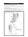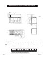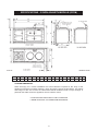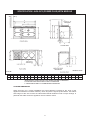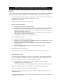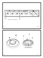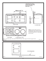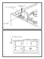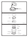
1
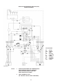
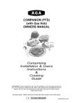
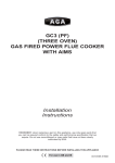
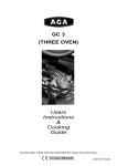
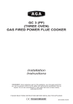
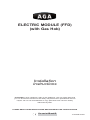
ELECTRIC MODULE (FFD)
(with Gas Hob)
Installation
Instructions
REMEMBER: when replacing a part on this appliance, use only spare parts that
you can be assured conform to the safety and performance specification that we
require. Do not use reconditioned or copy parts that have not been clearly
authorised by AGA.
PLEASE READ THESE INSTRUCTIONS BEFORE INSTALLING THIS APPLIANCE
For use in GB and IE
11/10 EINS 511621
CONTENTS
SECTION
PAGE
INTRODUCTION
3
TECHNICAL DATA
4
ELECTRICAL CONNECTION
5
LOCATION
6
SPECIFICATION - AGA GC (2 OVEN) WITH MODULE
7
SPECIFICATION - 3 OVEN AGA WITH MODULE (GC3M)
8
SPECIFICATION - AGA GC3 (POWER FLUE) WITH MODULE 9
INSTALLATION SEQUENCE AND PROCEDURE
10 - 16
SERVICING
17
WIRING DIAGRAM
18
2
INTRODUCTION
WARNING: THIS APPLIANCE SHALL BE INSTALLED IN ACCORDANCE WITH THE
REGULATIONS IN FORCE AND ONLY USED IN A WELL VENTILATED SPACE. READ THE
INSTRUCTIONS BEFORE INSTALLING OR USING THIS APPLIANCE.
PRIOR TO INSTALLATION, ENSURE THAT THE LOCAL DISTRIBUTION CONDITIONS
(NATURE OF THE GAS AND GAS PRESSURE) AND THE ADJUSTMENT OF THE
APPLIANCE ARE COMPATIBLE.
THE ADJUSTMENT CONDITIONS FOR THIS APPLIANCE ARE STATED ON THE DATA
PLATE.
THE DATA PLATE IS SITUATED IN THE CENTRE VENT SLOT NEAR THE BASE OF THE
FRONT PLATE.
This appliance is not connected to a combustion products evacuation device. It shall be installed
and connected in accordance with current installation regulations. Particular attention shall be
given to the relevant requirements regarding ventilation. (B.S. 5440 Part 2: 1989).
It should be in accordance also with any relevant requirements of the Gas Region and Local
Authority.
In your own interest, and that of safety to comply with the law, all gas appliances must be
installed by a competent person. Failure to install appliances correctly could lead to prosecution.
On completion, test the gas installation for tightness.
WARNING: THIS APPLIANCE MUST BE EARTHED.
The appliance is designed for the voltage stated on the data plate.
The appliance is supplied with and installed adjacent to the LH side of any one of the current
range of traditional AGA cookers.
Installation of the Module must, therefore, be in conjunction with the build instructions of the
‘parent’ AGA.
Reference must be made to the above Installation instructions for the ‘parent’ AGA especially
regarding pre-site inspection, not only for both cookers but to consider any pipework that may
pass at the rear of the Module. i.e. boiler piping or flue duct from a Fan Flue AGA.
The appliance has been designed to accommodate pipework passing at the rear.
NOTE! THE MAIN AGA COOKER IS DELIVERED EX-WORKS UNASSEMBLED.
ASSEMBLY IS UNDERTAKEN ON SITE, BY AN AUTHORISED AGA ENGINEER.
The Module is supplied from the manufacturers in a fully assembled condition
3
TECHNICAL DATA
HOTPLATE
NATURAL GAS G20 - (APPLIANCE CATEGORY I2H)
R.H.F.
L.H.R.
R.H.R.
L.H.F.
BURNER TYPE
ULTRA-RAPID RAPID
SEMI-RAPID
SEMI-RAPID
MAXIMUM HEAT
INPUT
3.5 kW
3.0 kW
1.75 kW
1.75 kW
INJECTOR MARKING
130
116
097
097
PRESSURE POINT POSITION: REAR LH SIDE OF APPLIANCE JUST BELOW HOTPLATE
LEVEL
PRESSURE SETTING:
20mbar
BURNER IGNITION: H.T. SPARK
(APPLIANCE CATEGORY I3+)
R.H.F.
L.H.R.
R.H.R.
L.H.F.
BURNER TYPE
ULTRA-RAPID RAPID
SEMI-RAPID
SEMI-RAPID
MAXIMUM HEAT
INPUT
3.5 kW
(250g/h)
(0.50 l/h)
3.0 kW
(214g/h)
(0.42 l/h)
1.75 kW
(125g/h)
(0.25 l/h)
1.75 kW
(125g/h)
(0.25 l/h)
INJECTOR MARKING
95
85
65
65
PRESSURE POINT POSITION: REAR LH SIDE OF APPLIANCE JUST BELOW HOTPLATE
LEVEL
PRESSURE SETTING:
G30: 28-30 mbar
G31 - 37 mbar
BURNER IGNITION: H.T. SPARK
ELECTRIC GRILL AND OVENS
GRILL ELEMENT - POWER RATING 2 x 1.05 kW
TOP OVEN - POWER RATING 1.0 kW
LOWER OVEN (FAN) - 1.9 kW
4
ELECTRICAL CONNECTION
Electrical connections are located at the back of the appliance.
Refer to Figs. 1 for wiring connection to the appliance.
Remember that an excess of cable length is required for the possible withdrawal of the cooker.
Always double check connections and ensure terminals are fully tightened and the cable is
secured to the cable clamp.
THE ISOLATOR SHOULD NOT BE POSITIONED IMMEDIATELY ABOVE THE MODULE, BUT
MUST BE SITED WITHIN 2 METRES OF THE APPLIANCE.
The Module requires a 30amp power supply fitted in conjunction with a double pole isolator with
a minimum contact clearance of 3mm and be connected to the mains with a minimum 4mm2
cable to comply with the latest editions of the local and national wiring regulations.
MINIMUM 4mm2 AND MUST COMPLY WITH THE LATEST EDITIONS OF THE LOCAL
AND NATIONAL WIRING REGULATIONS
DESN 513370
REMOVE
COVER
(4
SCREWS) TO GAIN ACCESS
TO THE MAINS TERMINAL
DESN 513372
FIG. 1
5
LOCATION
This is a class 2, type X appliance.
The side wall above the hob shall be greater than 60mm from the cooker, only when adjacent
to combustible material.
Surfaces over the top of the cooker must not be closer than 650mm.
The vent slots in the back of the top plate (or shroud) must not be obstructed.
If possible, any hot water pipes from the AGA Cooker should be routed away from the Module.
The extension channel section at the rear of each side plate may be removed, if required, to
clear hot water or flue pipes with the following provisos:If hot water pipes pass at the rear, they should be lagged and a 50mm air gap provided
on the LH side of the cooker.
Note: It is advisable that the supply cable is routed away from any hot surfaces i.e. hot
water/flue pipes.
In the interest of safety, due consideration must be given to the protection of the electric
cable to the module.
NOTE: The parent AGA may require a gas supply (See Figs. 2, 2A & 2B) and
‘INSTALLATION - Connecting to Gas’ section.
.
6
SPECIFICATIONS - AGA GC (2 OVEN) WITH MODULE
E
A
N
POSITION OF LIDS WHEN
RAISED
G
C
F
B
O
L
D
M
H
J
OVEN DOOR IN
OPEN POSITION
K
COOKER DIMENSIONS
When surveying for a cooker installation the actual clearance required for the ‘body’ of the appliance should be
increased overall by 10mm beyond the figures quoted below. This allows safe margin to take into account the
natural dimensional variations found in major castings. In particular the width across an appliance recess could be
critical.
A
B
C
D
***
E
mm 1598 889 851 679 60
FIG. 2
F*
G
H
J
K
967 1330 756 1125 116
* ELECTRIC AND GAS POWER FLUE MODELS ONLY
** POSITION FOR GAS SUPPLY PIPE TO MODULE
*** WHEN ADJACENT TO COMBUSTIBLE MATERIAL
7
L
3
M
N**
O**
698 1533 800
DESN 511633
SPECIFICATIONS - 3 OVEN AGA WITH MODULE (GC3M)
FIG. 2A
DESN 512430
A
B
C
D
E
F
G
H
J
K
L
M
N
mm 1598 889 851 679 467 1035 41 1330 756 1125 73
39
3
P
S
T
698 1533 800
U
W
60
116
COOKER DIMENSIONS
When surveying for a cooker installation the actual clearance required for the ‘body’ of the
appliance should be increased overall by 10mm beyond the figures quoted below. This allows
safe margin to take into account the natural dimensional variations found in major castings. In
particular the width across the appliance recess could be critical.
* POSITION FOR GAS SUPPLY PIPE TO MODULE
** WHEN ADJACENT TO COMBUSTIBLE MATERIAL
8
SPECIFICATION - AGA GC3 (POWER FLUE) WITH MODULE
DESN 513392
FIG. 2B
A
B
C
D
***
E
mm 1598 889 851 679 60
F
G
H
J
I*
K
967 1330 756 1125 685 116
L
3
M
N** O**
P
698 1533 800 48
Q
R
S
T
65 375 500 595 960
* GAS SUPPLY PIPE FOR GC3 (PF) WHEN FITTED TO MODULE
** POSITION FOR GAS SUPPLY PIPE TO MODULE
*** WHEN ADJACENT TO COMBUSTIBLE MATERIAL
COOKER DIMENSIONS
When surveying for a cooker installation the actual clearance required for the ‘body’ of the
appliance should be increased overall by 10mm beyond the figures quoted below. This allows
safe margin to take into account the natural dimensional variations found in major castings. In
particular the width across the appliance recess could be critical.
9
U
INSTALLATION SEQUENCE AND PROCEDURE
Installation must be to Local and National Wiring Regulations and carried out by a Qualified
Engineer.
Having ensured all space requirements and regulations have been satisfied for the combined
arrangement (AGA Cooker & Module), the build and installation is to proceed as follows:1.
It is essential that the base or hearth on which both cooker and module stands should be
level and capable of supporting the total weight of both units.
Module weight = 129 kgs.
2.
Unpack and remove the Module from the pallet.
3.
Remove top plate as follows:
a)
b)
c)
d)
e)
4.
Remove hotplate as follows:a)
b)
c)
d)
e)
5.
Remove pan supports and all control knobs.
Remove four chrome buttons and the four top plate retaining screws (2 each side).
Remove left hand and centre shrouds from the control panel to gain access to the
fixing screws. Remove two screws from control panel (one from left hand hole and
one from centre hole). (See Fig. 3)
Pull top plate forwards slightly and lift up at front. Support top plate and disconnect
wiring to the two neons. Remove top plate.
Lay the top plate on its top face, suitably protected.
Remove burner heads and burner caps.
Remove all of the screws retaining hotplate burner trims (4 from Wok burner, 2 each
from the other three burners). (See Fig. 4).
Carefully remove burner trims and gaskets, taking care not to damage gaskets or
burner electrodes.
Disconnect earth wire from left hand control panel mounting bracket.
Remove hotplate casting.
First check that the current is OFF.
Connect the mains wire to the terminal block at the rear of the cooker (See Fig. 1).
6.
CONNECTING TO GAS
The cooker must be installed by connection to rigid pipework, which should not be less
than 15mm diameter. Connection is made to the 15mm compression fitting located just
below the hotplate level on the rear left hand side of the cooker.
a)
b)
Mark off approximate position on wall for gas supply to cooker (See Fig. 2
Dimensions N and O, see also Fig. 5).
Isolate the gas supply and connect pipework as required up to the position marked.
NOTE: For connecting gas supply to AGA GC3 (Three Oven Model), see Fig. 5A.
Check for gas tightness after connecting the gas supply.
7.
Position the cooker alongside the main AGA baseplate leaving 16mm between the two
bases (See Fig. 6).
Check with a spirit level that the front plate is vertical and the ovens level. Shim under the
module base if necessary.
10
8.
Make final gas connection to the cooker (15mm compression) into the combined gas
cock/pressure test fitting (See Fig. 7). Check for gas tightness after connecting the gas
supply.
9.
PRESSURE TESTING
The pressure test point is situated at the rear left hand side of the appliance just below
hotplate level. (See Fig. 7).
Remove screw from pressure test nipple. Fit the pressure gauge onto the pressure test
nipple.
Turn the gas cock to the ON position.
Place one of the burner heads and burner cap into position on the burner body. Push in and
turn the appropriate control knob anti-clockwise to full-on position, and light the burner
with a match.
For Natural Gas appliance, the pressure should be nominal 20mbar (8 inches water
gauge).
For LPG appliance (propane) the pressure should be nominal 37mbar (14.8 inches water
gauge).
Turn off the tap, turn off gas cock, disconnect the pressure gauge and refit pressure test
screw to pressure test nipple.
Turn the gas cock back to the ON position.
Check for gas tightness.
10.
Proceed with the main AGA build in accordance with normal practice until a check can be
made that the Module front plate and AGA front are the same height and that the distance
between the two units has been maintained. If not, adjustment should be made to the
Module position.
11.
Levelling of the simmering plate on the main cooker can be carried out with its top plate
in position and verified across the Module. (See Fig. 8).
12.
Complete the main cooker build and loosely screw down the top plate.
13.
Apply tape (provided) to the underside of the lap strip on the Module top plate.
14.
Replace module hotplate. Reassemble in reverse order (See section 4). Ensure burner
heads and burner caps are correctly located (See Fig. 9A, 9B and 9C), and electrodes
are not damaged.
15.
Replace Module top plate as follows:a)
b)
c)
d)
Support top plate at front and reconnect the wiring to the two neons.
Carefully lower the top plate into position taking care not to damage wiring or neons.
Ensure holes for control spindles are aligned correctly, and replace 2 screws into
control panel.
Loosely screw the top plate down with 4 retaining screws.
16.
Verify that the two top plates are level.
17.
Secure handrails as shown on Instruction Sheet EINS 511080.
18
Finally tighten both top plates.
Commission the main AGA cooker, as stated in the relevant Installation Instructions and carry
out functional tests on each of the features on the Module. (See Users Instructions).
11
REMOVE 2 FIXING SCREWS
DESN 511645
FIG. 3
(WOK BURNER ONLY)
DESN 511646
FIG. 4
12
FIG. 5
DESN 511647
Gas Supply Connections
13
NOTE: A special rubber grommet is
provided to fill-in the ‘knock-out’ hole in
the side panel. Pierce the centre of the
grommet and pass the 1/4” gas supply
pipe through it.
Fig 5A - AGA GC3 (Open Flue) & GC3 Power Flue Only - Gas Supply Connections (approximate
positions)
DESN 512449
DESN 511254
FIG. 6
14
DESN 511648
FIG. 7
FROM SURFACE OF THE AGA TO
LUGS ON FRONT PLATE OF MODULE
64
TOP PLATE
OF MODULE
REMOVED
DESN 511255
FIG. 8
15
BURNER CAP
RETAINING LUGS
Fig. 9A
DESN 511617
Fig. 9B
DESN 513513
Fig 9C
DESN 513898
16
SERVICING
z
In the event of your appliance requiring maintenance please call AGA Service or contact
your authorised distributor/stockist.
z
Your cooker must only be serviced by a Qualified Engineer from an authorised distributor
or stockist.
z
Do not alter or modify the cooker.
z
Only the spares specified by the manufacturer are to be fitted.
17
AGA ELECTRIC MODUILE GAS HOB (FFD)
WIRING DIAGRAM
COLOUR KEY
BL
WH
R
BK
Y
PK
BR
P
GR
NOTE:
1.
IGNITION SWITCHES AND THERMOSTATS
ARE SHOWN IN THE OFF POSITION
WITH THE APPLIANCE COLD AND
FAN OVEN DOOR CLOSED.
2.
THE COOKER IS COLD
(IE. CUT-IN & CUT-OUT NOT OPERATED)
18
-
BLUE
WHITE
RED
BLACK
YELLOW
PINK
BROWN
PURPLE
GREY
19
For further advice or information contact
your local AGA Specialist
With AGA’s policy of continuous product
improvement, the Company reserves the right to
change specifications and make modifications to
the appliance described and illustrated at any time
Manufactured by
AGA
Station Road
Ketley Telford
Shropshire TF1 5AQ
England
www.aga-web.co.uk
www.agacookshop.co.uk
www.agalinks.com
20