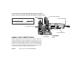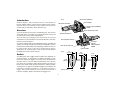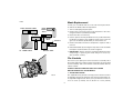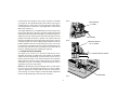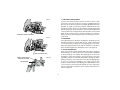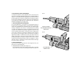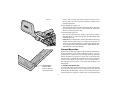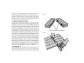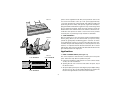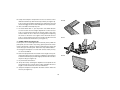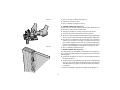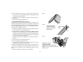
1
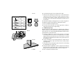
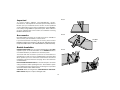
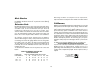
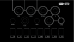
DEWALT Industrial Tool Company, 626 Hanover Pike, P.O. Box 158, Hampstead, MD 21074
Printed in U.S.A. (SEP95-CD-1) Form No. 154527
For information call toll free between 8:00 a.m. and 8:00 p.m. ET, seven days a week. 1-800-4-DEWALT (1-800-433-9258).
DW682
Copyright 1995
INSTRUCTION MANUAL
MANUAL DE INSTRUÇÕES
MANUAL DE INSTRUCCIONES
DW682 Plate Joiner
Fresadora DW 682
IF YOU HAVE ANY QUESTIONS OR COMMENTS ABOUT THIS OR ANY
DEWALT TOOL, CALL US TOLL FREE AT 1-800-4-DEWALT (1-800-433-9258).
Serial Number from Nameplate
Date of Purchase
AUXILIARY HANDLE
SPINDLE LOCK
PIN
LOCK ON BUTTON
DANG
_B
E R:
Save this information for future reference
ADJUSTABLE FENCE
R
0
15
30
45
60
75
90
NCE INDUSTR
GH PER
HI
DEWALT…BUILT JOBSITE TOUGH
D E WALT high performance industrial tools are made for America’s
toughest industrial and construction applications. The design of every tool
in the line—from drills to sanders to grinders—is the result of rigorous use
on jobsites and throughout industry. Each tool is produced with painstaking
precision using advanced manufacturing systems and intense quality
control. Every tool is checked before it leaves the factory to make sure that
it meets your standards for durability, reliability and power.
DEWALT
Built Jobsite Tough…WE GUARANTEE IT.
FIXED SHOE
IA
OOLS
MA
LT
RMA
FO
D E IN T H E U . S . A
TRIGGER SWITCH
.
PLUNGE DEPTH
ADJUSTMENT
KNOB
Important Safety Instructions
WARNING: When using Electric Tools, basic safety precautions should
always be followed to reduce risk of fire, electric shock, and personal
injury, including the following
•
Read all Instructions
•
•
KEEP WORK AREA CLEAN. Cluttered areas and benches invite injuries
CONSIDER WORK AREA ENVIRONMENT. Don’t expose power tools
to rain. Don’t use power tools in damp or wet locations. Keep work area
well lit.
GUARD AGAINST ELECTRIC SHOCK. Prevent body contact with
grounded surfaces. For example: pipes, radiators, ranges, refrigerator
enclosures.
KEEP CHILDREN AWAY. All visitors should be kept away from work
area. Do not let visitors contact tool or extension cord.
STORE IDLE TOOLS. When not in use, tools should be stored in dry,
and high or locked-up place - out of reach of children.
DON’T FORCE TOOL. It will do the job better and safer at the rate for
which it was intended.
USE RIGHT TOOL. Don’t force small tool or attachment to do the job of
a heavy-duty tool. Don’t use tool for purpose not intended, for example,
don’t use circular saw for cutting tree limbs or logs.
DRESS PROPERLY. Do not wear loose clothing or jewelry. They can be
caught in moving parts. Rubber gloves and non-skid footwear are
recommended when working outdoors. Wear protective hair covering to
contain long hair.
USE SAFETY GLASSES. Also use face or dustmask if cutting operation
is dusty.
DON’T ABUSE CORD. Never carry tool by cord or yank it to disconnect
from receptacle. Keep cord from heat, oil, and sharp edges.
SECURE WORK. Use clamps or a vise to hold work. It’s safer than
using your hand and it frees both hands to operate tool.
DON’T OVERREACH. Keep proper footing and balance at all times.
MAINTAIN TOOLS WITH CARE. Keep tools sharp and clean for better
and safe performance. Follow instructions for lubricating and changing
•
•
•
•
•
•
•
•
•
•
•
•
•
•
•
•
•
•
accessories. Inspect tool cords periodically and if damaged have
repaired by authorized service facility. Inspect extension cords
periodically and replace if damaged. Keep handles dry, clean, and free
from oil and grease.
DISCONNECT TOOLS. When not in use, before servicing, and when
changing accessories, such as blades, bits, cutters.
REMOVE ADJUSTING KEYS AND WRENCHES. Form habit of
checking to see that keys and adjusting wrenches are removed from tool
before turning it on.
AVOID UNINTENTIONAL STARTING. Don’t carry plugged-in tool with
finger on switch. Be sure switch is off when plugging in.
OUTDOOR USE EXTENSION CORDS. When tool is used outdoors,
use only extension cords intended for use outdoors and so marked.
STAY ALERT. Watch what you are doing. Use common sense. Do not
operate tool when you are tired.
CHECK DAMAGED PARTS. Before further use of the tool, a guard or
other part that is damaged should be carefully checked to determine that
it will operate properly and perform its intended function. Check for
alignment of moving parts, binding of moving parts, breakage of parts,
mounting, and any other conditions that may affect its operation. A guard
or other part that is defective should be properly repaired or replaced by
an authorized service center unless otherwise indicated elsewhere in this
instruction manual. Have defective switches replaced by authorized
service center. Do not use tool if switch does not turn it on and off.
DO NOT OPERATE portable electric tools near flammable liquids or in
gaseous or explosive atmospheres. Motors in these tools normally spark,
and the sparks might ignite fumes.
SAVE THESE INSTRUCTIONS FOR FUTURE USE
1
Introduction
Examine Figure 1 and your plate joiner for a few minutes to
become familiar with the various features and the names used to
describe them. The following sections will discuss the various
controls and you will need to know where they are.
FIG 1
AUXILIARY HANDLE
LOCK KNOB
LOCK ON BUTTON
HEIGHT ADJUSTMENT
KNOB
R
Overview
DUST EXHAUST PORT
You have purchased a precision woodworking tool. The function
of the plate joiner is to enable you to make extremely strong and
accurate joints in wood and wood byproducts.
The tool works by a plunging action to precisely cut crescent
shaped slots for the placement of flat wooden dowels or “biscuits”
like those shown in Figure 2.
The various adjustments on the patented base/fence assembly will
enable you to make virtually any biscuit joint imaginable. The tool
may be further enhanced by some simple jigs and fixtures that can
be easily made. Some of the more common biscuit joinery
applications are shown in Figure 3 and are discussed in detail in
the applications section of this manual.
TRIGGER SWITCH
R
ADJUSTABLE FENCE
PLUNGE
DEPTH
ADJUSTMENT
KNOB
ANTI-SLIPPAGE PIN
LOCK KNOB
FIG 2
1/2"
(12.7 mm)
Switch
Your plate joiner has a trigger switch located on the underside, as
shown in Figure 1. To turn the tool on, depress the trigger. To turn
the tool off, release the trigger. To lock the tool on for continuous
operation, there is a lock on button located at the rear of the tool
just above the cord. When cutting always hold the tool with one
hand on the switch handle and one hand on the auxiliary handle.
To lock the tool on, depress and hold the trigger as you depress the
lock button. Hold the lock button in as you gently release the
trigger. The tool will continue to run. To turn the tool off from a
locked on condition, depress and release the trigger once.
2 3/8"
(60 mm)
(flat biscuits)
2
3/8"
(9.5 mm)
2 3/16"
(56 mm)
#20
5/16"
(8 mm)
1 13/16"
(46mm)
#10
#0
Blade Replacement
FIG 3
EDGE TO EDGE JOINT
In time your saw blade will wear out and need replacement.
To remove the blade, follow the steps below.
1. Turn off and unplug the plate joiner.
2. Remove the 4 torx head screws from the bottom of the shoe,
using the T20 torx screwdriver provided.
3. Rotate the shoe out of the way.
4. Use the spanner wrench provided to loosen (counterclockwise)
the blade nut. Depress the spindle lock pin on the top of the
gear case to hold the spindle while you unscrew the nut.
5. Remove the blade and have it sharpened or replace it with a
new one.
6. Reinstall the blade by reversing the steps above. Be sure blade
teeth point counterclockwise as shown in Figure 4.
7. IMPORTANT: Always check the fine depth adjustment when
sharpening or replacing the blade. Adjust if necessary.
(See “Controls” section).
EDGE
MITRE
JOINT
"T" JOINT
CORNER
JOINT
45° FRAME JOINT
OFFSET
OFFSET JOINT
The Controls
The heart of your plate joiner is the base/fence assembly. All of
the controls that let you make a variety of precision cuts are located
on this assembly. Take a few minutes to become familiar with the
various controls.
ALWAYS TURN OFF AND UNPLUG PLATE JOINER
BEFORE MAKING ANY ADJUSTMENTS.
R
1. ADJUSTABLE FENCE
The adjustable fence provides a sturdy, precise reference surface
to determine the point at which the slots for the biscuits will be cut.
Its adjustable height feature allows you to position biscuit slots as
close as 3/16" (4.76mm) and as distant as 1-3/8" (35mm)
FIG 4
3
measured from the workpiece surface to the centerline of the blade
(see Figure 6). The adjustable angle feature allows a full range of
settings from 0° to 90 as well as a reverse 45° bevel which allows
outside registration on miter joints. (See Applications section under
Miter Joints, Figure 27.)
The height adjustment is accomplished by first loosening the lock
knob on the right side of the fence and then rotating the knurled
adjustment knob until the desired height is reached (see Figure 5).
Tightening the lock knob will then automatically align the fence
parallel to the blade and lock it in position. The vertical scale and
pointer located directly under the lock knob can be used to assist in
setting this height. The scale readings indicate distance from the
blade centerline to the fence surface when the fence is set at 90°
(see Figure 6). If the depth scale ever needs to be adjusted, loosen
the two screws that secure the scale and move the scale until the
pointer is indicating the proper reading (see Figure 6).
FIG 5
ADJUSTMENT
KNOB
LOCK KNOB
FIG 6
2. PLUNGE DEPTH ADJUSTMENT
The depth of cut can be set to match the dimensions of the
particular size biscuit you will be using. The numbers on the depth
adjustment knob (0,10,20,M) coincide with the three sizes of
biscuits shown in Figure 2. The letter M stands for the maximum
depth capacity of the tool which is 20mm (25/32"). This depth is
obtainable only with a new blade and by backing out the fine
adjustment screw (see next section).
NOTE: The M setting has been provided for future use and will not
be necessary for most biscuiting operations. To select a depth,
align the appropriate number with the red mark scribed in the
tool’s housing, as shown in Figure 7. Rotate the depth adjustment
knob to the desired position and it will “click” into place.
POINTER POINTS
TO 1/2" MARK
1/2" CENTERLINE OF BLADE
R
20
M
0
10
RED MARK
FIG 7
4
FIG 8
3. FINE DEPTH ADJUSTMENT
You may encounter situations where you want to leave a little
looseness in your joint so that you can move it slightly before the
glue sets up. For these instances a fine depth adjustment has been
provided. To adjust, you must first raise the adjustable fence to its
uppermost position. Then insert the T20 torx screwdriver provided
into the opening as shown in Figure 8. Turn the depth adjustment
screw clockwise for less depth and counterclockwise for increased
depth. Each full turn causes a change in depth of 1mm (0.04").
Always check the depth adjustment by first making test cuts in
scrap wood.
R
FINE DEPTH ADJUSTMENT
FIG 9
4. ALIGNMENT
If the adjustment fence becomes misaligned to the blade, use the
following procedure to realign: With the two support attachment
screws (located just above the anti-slippage pins) loosened,
adjust the support position to be flush to the bottom of the base.
Then carefully retighten the attachment screws (see Figure 9).
R
5. ANTI-SLIPPAGE PINS
Plate Joiners tend to slide to the right with respect to the workpiece
when making a cut. This tendency is increased with a dull blade
or when plunging very rapidly. Anti-slippage pins have been
provided to reduce this tendency and are located on the front
registration surface on either side of the blade opening slot. When
making some joints, you may wish to retract the anti-slippage pins
so as not to scratch your workpiece in a visible area. For this
purpose, simply rotate the anti-slippage pins approximately 1/6 of
a turn and they will retract back behind the front registration
surface. A flat blade screwdriver can be used to rotate the pins as
shown in Figure 9.
ANTI-SLIPPAGE PIN
FIG 10
ANGLE INDICATING
POINTER SCREW
LOCK KNOB
45
0
5
6. ADJUSTABLE FENCE SQUARENESS
To adjust the squareness of the adjustable fence to the front of the
unit, loosen the angle indicating pointer screw, and while holding a
square in contact between the adjustable fence and the front of
the unit, tighten the lock knob. Carefully place the indicator against
the stop on the 90 degree end of the angle scale and retighten the
screw. When the angle indicator is against the stop, the pointer
will indicate 90 degrees (see Figure 10).
FIG 11
7. BOTTOM REGISTRATION SURFACE
For certain applications, you will want to use the bottom surface of
the plate joiner for alignment. When using the bottom registration
surface, the adjustable fence should be set to 0° and the height
setting is unimportant. This surface is used primarily when making
‘T’ joints (see applications section). The distance between the
centerline of the blade and the bottom registration surface is fixed
at 3/8" (9.5mm) which allows centering on 3/4" (19mm) thick
stock. The 3 red marks on the bottom registration surface indicate
the centerline (or the deepest point) of the biscuit cut and the
approximate width of a #20 biscuit so that you’ll know where the
edge of the blade is and can prevent breakthrough. To avoid
breaking through the workpiece, align the shoe so that neither
outside mark extends beyond the end of the workpiece. If either
side does, there is a good chance that the blade will break through
the surface and ruin your work.
R
ROTATE ELBOW
FOR DESIRED EXHAUST
DIRECTION
FIG 12
R
8. DUST EXTRACTION
There are three options provided for collecting dust from your
plate joiner as described below.
A. Adjustable Direction Elbow (See Figure 11)
This attachment inserts into the dust exhaust port on the right
side at the rear of the base assembly and clicks into place. To
VACUUM HOSE
CONNECTION
6
FIG 13
remove, pull out firmly. The directional elbow rotates easily to
aim the dust in the most convenient direction suitable for the
particular application.
B. Dust Adaptor (See Figure 12)
This attachment, when inserted as described above, allows the
use of several common sizes of vacuum hose to be attached for
direct vacuum pick-up of the dust.
C. Dust Bag (See Figure 13)
The dust bag provided fits snugly over the dust adaptor
described above. To empty the bag, open the zipper underneath
and dump dust out.
NOTE: When the bag becomes full, the dust will back-up into the
adaptor and the exhaust port on the right rear of the tool. To
clean out, turn off and unplug the tool and remove packed dust.
The bag will hold the dust generated from approximately 70 to
100 #20 biscuit cuts before filling up.
R
R
FIG 14
General Operation
Plate joiners are primarily used for making cabinetry and furniture,
joining millwork or other similar applications where a strong,
accurate joint is required in wood or wood by-products. There are
literally hundreds of variations of joints that can be made with
your Plate Joiner. We will limit our discussion to six basic joints that
can be used to build on and adapt to your own applications.
The following are some basic set-up steps that will apply to all
biscuit joints.
PROTRUDING
BISCUIT END
(Trim off with saw
and sand smooth)
1. BISCUIT SIZE SELECTION
As mentioned earlier, the three biscuit sizes are #0, #10 and #20.
It is a good rule of thumb to use the largest biscuit size that will
physically fit in the application. Unless you are joining narrow face
or picture frames or using 1/2" or thinner stock, you will find the #20
7
biscuit size to suit most applications. After selecting the biscuit size,
set the depth adjustment knob to the corresponding size (see
Controls section). Also, be sure the fine depth adjustment is
correctly set by first testing in a scrap piece. This is extremely
important as you do not want to discover during glue-up that your
biscuit slots are not quite deep enough.
FIG 15
2. BISCUIT LOCATION AND LAYOUT
Generally, biscuits may be spaced and located at your discretion.
For edge joints, a good rule of thumb is to space biscuits every
6-10 inches on center. It is further recommended that biscuits be
placed so that the centerline of the end biscuits is 2-3 inches from
the end of the workpiece. When joining face frames or picture
frames where the workpiece is narrow, you may have to choose the
smaller biscuit sizes to keep from “breaking out” on the end of the
joint. Breaking out should be avoided if possible, but if not you can
assemble the joint and trim off the exposed biscuit tip after the glue
sets (see Figure 14). When working with material up to 1" thick, we
advise to use a single biscuit located in the approximate center of
the material thickness. If thicker stock is to be joined, you may
choose to use 2 biscuits across the thickness for greater strength
(see Figure 15). Biscuit locations should be marked by first
positioning the mating pieces exactly as they are to be assembled.
Next, make a mark at 90° to the joint interface across both pieces at
the desired biscuit locations (see Figure 16). See Application
section for more specific information on joint layout. The marks you
make will then be aligned with one of the center registration marks
on the tool, again, depending upon your specific application.
1" OR GREATER STOCK THICKNESS
FIG 16
3. MAKING THE CUT
Prior to making any cut, be sure that all fence adjustments are set
and lock knobs are tight. Also, be sure you have selected the proper
depth setting. Clamp your workpiece firmly and align the plate
8
FIG 17
2"-3"
joiner’s center registration mark with your layout mark. Turn on the
tool and let the blade come up to full speed (approximately
1 second). Grasping the switch handle and auxiliary handle and
positioning the fence firmly and squarely against the workpiece,
plunge the blade until it bottoms against the stop. Continuing to hold
the tool squarely and firmly, allow the return spring to retract the
blade from the work and then release the switch to shut the tool off.
It will take some practice to obtain a “feel” for the tool to produce
accurate joints, so practicing in scrap wood first is advisable.
6"-10"
4. JOINT ASSEMBLY
After your joints are cut, you may wish to trial fit everything together
before gluing. When you are satisfied with your joints, evenly
spread any good quality woodworking glue in each slot as well as
on the mating flat surfaces of your joint. Place biscuits in the slots,
assemble the joint and clamp until dry. For a biscuit joint to be most
effective, it is important that the biscuits themselves be in contact
with the glue. This is because the biscuits absorb the moisture in the
glue and expand to form a tight joint.
FIG 18
R
Applications
1. EDGE TO EDGE JOINTS (See Figure 17)
This is the simplest to make and most common joint for the plate
joiner. Follow the steps below to produce this joint.
A. Prepare the workpieces and lay them on a work surface exactly
as they are to be assembled.
B. Spacing biscuits 2-3" in from the ends and 6-10" apart, layout
the biscuit centers.
C. Set up the plate joiner by first selecting the proper depth setting.
Set the fence to 90°. Set the height adjustment to position the
biscuit in the approximate center of the stock thickness.
FIG 19
3/16" MINIMUM
3/16" MINIMUM
3/16" MINIMUM
9
D. Clamp the workpiece and position the tool so that the center
indicator mark lines up with the first layout mark (see Figure 18).
Turn on the tool and make the plunge cut. Retract the tool and
release the trigger to turn the tool off. Repeat for each layout mark.
E. Glue, assemble and clamp the joint.
F. For stock thicker than 1", you may wish to use double biscuits
at each location. Set the height adjustment to allow at least
3/16" of stock between the biscuit and the edge of the work
surface. Make all cuts at this fence setting before readjusting
the fence for the lower cuts. Again, there should be at least
3/16" of stock between the biscuit and the outside wall and
between the biscuits themselves (see Figure 19).
FIG 20
FIG 21
2. FRAME JOINTS (See Figure 20)
Frame joints are an ideal application for biscuit joinery. With the
plate joiner you can create a very strong, precise joint that is much
faster to make than a dowel or mortise and tenon joint. Figure 20
shows two types of frame joints. Follow the steps outlined below.
A. Arrange the workpieces on a flat work surface exactly as they
are to be assembled.
B. Select the proper biscuit size based on the length of the joint.
(If the frame pieces are too narrow for a #0 biscuit, you will have
to allow the biscuit tip to protrude slightly and then trim it off after
the joint is dry (see Figure 14).
C. Lay out the biscuit locations.
D. Set up the tool by selecting the depth that corresponds to the
chosen biscuit size. Lock the fence at 90° and adjust the fence
height to center the biscuit on the stock thickness.
E. Clamp the workpiece and position the Plate Joiner to make the
first cut (see Figure 21).
R
FIG 22
10
FIG 23
F. Turn on the tool and make the plunge cut.
G. Repeat for each layout mark.
H. Glue, assemble and clamp the frame.
3. CORNER JOINTS (See Figure 22)
Corner joints are another common and excellent application for
biscuit joinery. Follow the procedure below.
A. Arrange the workpieces exactly as they are to be joined.
B. Select the biscuit size and layout the biscuit locations.
C. Set up the tool by selecting the proper depth setting, adjusting the
fence to center on the stock thickness and setting the angle to 90°.
D. For this joint, you will make cuts into the edge of one workpiece
and the face of another. The edge cut is performed the same
as for edge to edge joints. The face cut is made by clamping the
workpiece and aligning the tool as shown in Figure 23. Turn the
tool on, make the plunge cut and repeat for each layout mark.
E. Glue, assemble and clamp the joint.
R
FIG 24
4. OFFSET JOINTS (See Figure 24)
You may wish to have a deliberate offset between two workpieces.
This is easily accomplished with your plate joiner by performing the
following steps.
A. Arrange the workpieces as they are to be assembled and layout
the biscuit locations.
B. Set up the tool by selecting the proper biscuit size and adjusting
the fence angle to 90°. Select the workpiece that will be set back
and adjust the fence height to center the cut within the thickness
of that piece.
C. Clamp the workpiece, align the tool and make the plunge cut.
11
D. Next, adjust the fence up by an amount equal to the desired
offset. Use the scale and pointer located on the right side of the
tool under the fence lock knob.
E. Clamp the second workpiece, align the tool and make the
plunge cut.
F. Glue, assemble and clamp the joint.
FIG 25
5. EDGE MITER JOINTS (See Figure 25)
Edge miters are most commonly used in box structures or for
making multisided pedestals where you would like to hide the end
grain. Once again, biscuit joinery is an outstanding method to use
both for added strength as well as ease of assembly. Follow the
steps below to assemble a 90° joint.
A. Position the workpieces as they are to be assembled and layout
biscuit locations on the outside of the joint.
B. Set up tool by first setting fence angle to 90°. Make the fence
adjustment such that the biscuit is located toward the inside of
the joint where the material is thicker, then select the biscuit size
so that the blade does not protrude through the outside wall
when the cut is made (see Figure 26).
C. Clamp the workpiece and align the tool as shown in column in
Figure 27.
D. Turn on the tool and make the plunge cut.
E. Glue, assemble and clamp the joint.
F. For joints other than 90° see outside registration column
Figure 28 for proper fence angle setting.
The above method will produce a joint where the outside surfaces
of the joint are aligned. If you wish to produce a joint where the
inside surfaces are aligned, use the following procedures for a 90°
joint.
A. Position workpieces as they are to be assembled.
FIG 26
POSITION BISCUIT
CLOSER TO INSIDE
EDGE TO INCREASE
DIMENSION “A”
INSIDE
EDGE
A
FIG 27
REVERSE 45° BEVEL:
ALLOWS OUTSIDE
REGISTRATION ON MITER JOINTS.
(NOTE: The tool is registered against the
outside surface.)
12
FIG 28
#
OF SIDES JOINT ANGLE
B. Layout biscuit locations on the inside of the angle.
C. Set up tool by setting fence angle to 45°. Set vertical fence
adjustment so that the biscuit is located toward the inside of
the joint where material is thicker. Select biscuit size so that
the blade does not protrude through the outside face of
the material.
D. Clamp the workpiece and align the tool as shown in Figure 29.
E. Make the plunge cut and repeat for all biscuit locations.
F. Glue, assemble and clamp the joint.
G. For joints other than 90° see inside registration column in
Figure 28 for proper fence angle setting.
FENCE ANGLE SETTING
OUTSIDE REGISTRATION INSIDE REGISTRATION
90
4
5
6
8
90
108
120
135
45
81
54
75
60
67.5
67.5
4
5
6
8
6. T-JOINTS (Figure 30)
Biscuit joining is a viable alternative to dadoing when making a
T-joint. T-joints are most commonly used when attaching shelves
to the sides of a case. The method described below will work if your
shelf material is at least 5/8" thick.
A. Place the workpieces on a work surface exactly as you will be
assembling them in the form of an upside down “T.” Mark
lightly along the joint where the top of the shelf is to end up
(see Figure 31). Mark biscuit locations at the joint interface on
the shelf piece only.
B. Lay the shelf down on the mating workpiece. Clamp the two
workpieces together and to the work surface in this position
(see Figure 32).
C. Set up the tool by selecting the proper biscuit size and setting
the adjustable fence angle at 0°.
D. Using the bottom registration surface, align the tool with the
biscuit location marks and make a vertical and a horizontal
plunge cut for each biscuit location as shown in Figure 33.
E. Glue, assemble and clamp the joint.
FIG 29
FIG 30
“T” JOINT
13
Important
FIG 31
To assure product SAFETY and RELIABILITY, repairs,
maintenance, and adjustment should be performed by Black &
Decker (U.S.) Inc. Industrial Service Centers or other qualified
service organizations. These service organizations service DeWALT
tools always using DEWALT replacement parts. Black & Decker
(U.S.) Inc. industrial tool service centers are certified for servicing
DEWALT industrial tools.
FIG 32
Accessories
Recommended accessories for use with your tool are available at
extra cost from your local dealer or service center.
If you need assistance in locating any accessory, please contact
DeWALT Industrial Tool Company, P.O. Box 158, 626 Hanover Pike,
Hampstead, MD 21074 or call 1-800-4-DEWALT (1-800-433-9258).
LAYOUT
LINE
Double Insulation
DOUBLE-INSULATED tools are constructed throughout with TWO
separate “layers” of electrical insulation or one DOUBLE thickness
of insulation between you and the tool’s electrical system.
Tools built with this insulation system are not intended to be
grounded. As a result, your tool is equipped with a two-prong plug
which permits you to use extension cords without concern for
maintaining a ground connection. See page 15 for more extension
cord information.
NOTE: DOUBLE-INSULATION does not take the place of normal
safety precautions when operating this tool. The insulation system
is for added protection against injury resulting from a possible
electrical insulation failure within the tool.
CAUTION: When servicing all tools, USE IDENTICAL REPLACEMENT PARTS. Repair or replace damaged cords.
FIG 33
R
14
Motor Brushes
Before using an extension cord, inspect it for loose or exposed wires,
damaged insulation, and defective fittings. Make any needed repairs or
replace the cord if necessary.
DeWalt uses an advanced brush system which automatically stops
the drill when the brushes wear out. This prevents serious damage
to the motor.
Full Warranty
Extension Cords
DEWALT heavy duty industrial tools are warranted for one year from
date of purchase. We will repair, without charge, any defects due to
faulty materials or workmanship. Arrangements have been made
with the Industrial Tool Division of Black & Decker (U.S.) Inc. to
provide warranty repairs for D E WALT tools. Please return the
complete unit, transportation prepaid, to any Black & Decker (U.S.)
Inc. Industrial Service Center or Authorized Service Station listed
under “Tools, Electric” in the Yellow Pages. This warranty does not
apply to accessories or damage caused where repairs have been
made or attempted by others. This warranty gives you specific
legal rights and you may have other rights which vary from state to
state.
In addition to the warranty, DEWALT tools are covered by our:
30 DAY NO RISK SATISFACTION GUARANTEE
If you are not completely satisfied with the performance of your
D E WALT heavy duty industrial tool, simply return it to the
participating seller within 30 days for a full refund. Please return the
complete unit, transportation prepaid. Proof of purchase may be
required.
Double insulated tools have 2-wire cords and can be used with 2wire or 3-wire extension cords. Only round jacketed extension cords
should be used, and we recommend that they be listed by
Underwriters Laboratories (U.L.) (C.S.A. in Canada). If the
extension will be used outside, the cord must be suitable for outdoor
use. Any cord marked as outdoor can be used for indoor work. The
letters “WA” on the cord jacket indicate that the cord is suitable for
outdoor use.
An extension cord must have adequate wire size (AWG or
American Wire Gauge) for safety, and to prevent loss of power and
overheating. The smaller the gauge number of the wire, the greater
the capacity of the cable, that is 16 gauge has more capacity than
18 gauge. When using more than one extension to make up the
total length, be sure each individual extension contains at least the
minimum wire size.
To determine the minimum wire size required, refer to the chart
below.
CHART FOR MINIMUM WIRE SIZE (AWG)
OF EXTENSION CORDS
NAMEPLATE
RATING-AMPS
0 - 10.0
10.1 - 13.0
13.1 - 15.0
TOTAL EXTENSION CORD LENGTH-FEET
25
50
75 100 125 150 175 200
18
16
14
18
16
14
16
14
12
16
14
12
14
14
12
14
12
12
12
12
12
See ‘Tools-Electric’
– Yellow Pages –
for Service & Sales
12
12
—
15