1
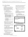
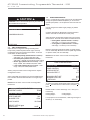
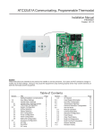
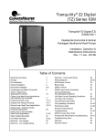
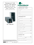
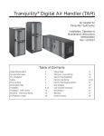
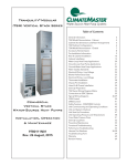
ATC32U02 iGate™ Communicating,
Programmable Thermostat
Installation Manual
97B0055N03
Rev.: 2/24/14
Caution:
These instructions are intended to be used by the installer or service personnel. End users are NOT advised to change or
modify any of these settings. Doing so may cause the equipment to stop working properly and/or may void the warranty on
both the thermostat and the equipment.
Table of Contents
Section
1.0
2.0
2.1
2.2
3.0
3.1
3.2
3.3
3.4
3.5
3.6
4.0
4.1
4.2
4.3
Title
Safety/Installation Considerations
User Menu Settings
Installer Menu Settings
Installer Menu Settings Access
Thermostat Configuration
System Configuration
Airflow Selection
Option Selection
Unit Configuration
Pump Configuration
Valve Configuration
Multi-Unit Configuration
Accessory Configuration
Air Filter
Humidifier
UV Lamp
Page
3
4
6
6
6
7
7
7
8
8
9
9
10
10
10
10
Section
4.4
5.0
6.0
7.0
8.0
9.0
9.1
9.2
9.3
9.4
9.5
9.6
9.7
10.0
11.0
Title
Air Cleaner
Input Dealer Information
Humidity Configuration
Temperature Algorithm
Demand Reduction Configuration
Service Mode
Manual Operation
Control Diagnostics
Dipswitch Configuration
Fault History
Clear Fault History
Multi-Unit Diagnostics
Multi-Unit Fault Information
Restore Defaults
Revision History
Page
10
10
11
11
12
12
12
12
13
13
14
14
15
15
16
This page was intentionally left blank.
AT C 3 2 U 0 2 C o m m u n i c a t i n g , P r o g r a m m a b l e T h e r m o s t a t - I O M
R e v. : 2 4 F e b . , 2 0 1 4
ClimateMaster’s ATC32U** Communicating, Programmable
Thermostat is the perfect compliment to a ClimateMaster
Geothermal Heat Pump System and represents a significant
advancement in thermostat communicating technology. For
homeowners, the ATC32U** provides highly customizable climate control features designed to maximize comfort and reduce the amount of energy consumed by the ClimateMaster
Geothermal Heat Pump System. For dealers, it represents
a significant, industry leading advancement in configuration,
monitoring and diagnostics from the thermostat. Please read
the following instructions carefully to maximize the comfort
and cost-saving potential of your ClimateMaster Geothermal
Heat Pump System.
SAFETY CONSIDERATIONS
Improper wiring or installation may damage thermostat. Wiring must conform to local and national electrical codes
WARNING!
WARNING! Before installing thermostat, turn off all
power to unit. There may be more than one power
disconnect. Electrical shock can cause personal
injury or death.
INSTALLATION CONSIDERATIONS
The thermostat requires no batteries. The thermostat is not
a power stealing device and MUST have both R and C terminals connected. See Diagram 1.
INSTALLATION
I. THERMOSTAT LOCATION
Thermostat should be mounted:
• Approximately 5 ft. (1.5m) above floor.
• Close to or in a frequently used room, preferably on an
inside partitioning wall.
• On a section of wall without pipes or duct work.
Thermostat should NOT be mounted:
• Close to a window, on an outside wall, or next to a
door leading to the outside.
• Exposed to direct light and heat from a lamp, sun,
fireplace, or other temperature-radiating object which
may cause a false reading.
• Close to or in direct airflow from supply registers.
• In areas with poor air circulation, such as behind a
door or in an alcove.
II. THERMOSTAT INSTALLATION
1. Turn off all power to unit.
2. If an existing thermostat is being replaced:
A. Remove existing thermostat from wall.
B. Disconnect wires from existing thermostat, one at
a time. Be careful not to allow wires to fall back
into the wall.
C. As each wire is disconnected, record wire color
and terminal marking.
D. Discard or recycle old thermostat.
NOTE: Mercury is a hazardous waste and MUST be disposed of properly.
3. Separate the thermostat from base.
4. Route thermostat wires through hole in base. Level
base against wall (for aesthetic value only - thermostat need not be leveled for proper operation) and
mark wall through 2 mounting holes.
5. Drill two 3/16-in. mounting holes in wall where
marked. (Note: Mounting holes on thermostat are
designed to fit on a horizontal J-box).
6. Secure base to wall with 2 anchors and screws
provided making sure all wires extend through hole in
base.
7. Connect wires to proper terminal of the connector
block in the thermostat.
8. Push any excess wire back into wall. Excess wire
inside the thermostat case can interfere with proper
air flow across the temperature sensor. Seal hole in
wall to prevent air leaks. Leaks can affect operation.
9. Install thermostat on base.
10. Turn on power to the unit.
III. WIRING DIAGRAMS
All excess wire should be pushed back into the wall as far as
possible. Excess wire inside the thermostat plastic case may
interfere with the air flow across the temperature sensor.
Diagram 1: Thermostat Connections
DXM2
Control
ATC32U** Thermostat
24Vac Common
C
Comm +
A+
24Vac Hot
R
Comm -
B-
Gnd
A+
B24V
OD
GND
ID
Outdoor
Sensor
(Optional)
Remote Indoor
Sensor
(Optional)
Thermostat Connections
C
24V Common for Control Circuit
R
24V Supply for Control Circuit
A+
Communications (Positive)
B–
Communications (Negative)
GND Ground
OD
Outdoor Temperature Sensor
ID
Indoor Temperature Sensor
3
AT C 3 2 U 0 2 C o m m u n i c a t i n g , P r o g r a m m a b l e T h e r m o s t a t - I O M
R e v. : 2 4 F e b . , 2 0 1 4
The Auto Changeover Time is the amount of time that
elapses before operation switches from heating to
cooling mode or from cooling to heating mode.
1.0 User Menu Settings
1.1 OFFSETS
If you find that the temperature displayed on the
thermostat does not accurately represent the room
temperature where the thermostat is located, this
offset function compensates for the difference.
The thermostat will apply an offset between what
temperature the thermostat is measuring versus the
temperature that is displayed.
Adjust the Auto Changeover Time using the up/
down arrow buttons. Press the center button to save
changes.
• Auto Change Over Time (default 15 minutes):
options: 0 to 120 minutes (in 15 minute
increments)
1.3 DEMO MODE
Demo mode is designed to showcase heat pump
operation when the unit is connected to an above
ground water loop with the supply air being blown
directly over the water loop.
1.1.1 TEMPERATURE OFFSET
The Temperature Offset function allows for
calibration of the temperature sensor.
Adjust the Temperature Offset settings using the
up/down arrow buttons. Press the center button to
save changes.
• Indoor Temperature (default 0°F): options:
-5°F to +5°F (in 1°F increments)
• Remote Temperature (default 0°F): options:
-5°F to +5°F (in 1°F increments)
• Outdoor Temperature (default 0°F): options:
-5°F to +5°F (in 1°F increments)
•
•
•
1st Stage (default 1°F): options: 1°F to 4°F
(in 1°F increments)
2nd Stage (default 1°F): options: 1°F to 4°F
(in 1°F increments)
Aux Heat (default 1°F): options: 1°F to 4°F
(in 1°F increments)
NOTE 1: The thermostat must be configured for
Multistage by installer to access the 2nd Stage
Differential setting. The thermostat must be
configured for Auxiliary Heat by installer to access
the Auxiliary Heat Differential setting.
NOTE 2: The temperature control algorithm must
be configured for Differential control to access the
Differential settings by installer.
1.1.2 HUMIDITY OFFSET
If you find that the Humidity level displayed on
the thermostat does not accurately represent the
Humidity level of the room in which the thermostat
is located, use the Humidity Offset function to
calibrate the humidity sensor.
Adjust the Humidity Offset setting using the up/
down arrow buttons. Press the center button to
save changes.
•
Indoor Humidity (default 0%): options:
-10% to +10% (in 1% increments)
1.3.1 ENTER DEMO MODE
To enter Demo Mode, navigate to the Service
Information screen (Menu>Settings>Service
Information) then press and hold the right arrow for
5 seconds
SERVICE INFORMATION
FAULT STATUS
CLEAR FAULT HISTORY
SYSTEM STATUS
SELECT OPTION
PREVIOUS
1.3.2 DEMO MODE OPERATION
Control Demo Mode operation parameters from the
Demo Operation screen shown below.
DEMO OPERATION
OUTDOOR
78%
RH 36%
72%
AUTO
SETPOINT
HEAT 70
COOL 74
RH
TEMP
1.2 AUTO CHANGEOVER TIME
When the thermostat is configured for AUTO mode,
the thermostat automatically selects heating or
cooling mode depending on the indoor temperature.
4
FAN AUTO
HEATING
HUMID ON
Geothermal Heat Pump Systems
MODE
FAN
MENU
AT C 3 2 U 0 2 C o m m u n i c a t i n g , P r o g r a m m a b l e T h e r m o s t a t - I O M
R e v. : 2 4 F e b . , 2 0 1 4
The starting mode (heating or cooling) depends
on the loop temperature at the time when Demo
Mode is entered. The unit will operate in heating or
cooling based upon the following algorithm.
Start in Cooling Mode
Start in Heating Mode
90°F
70°F
50°F
Solid lines represent heating operation. Dashed lines represent
cooling operation.
1.3.3 EXITING DEMO MODE
To exit demo mode, remove power to the
thermostat.
5
AT C 3 2 U 0 2 C o m m u n i c a t i n g , P r o g r a m m a b l e T h e r m o s t a t - I O M
R e v. : 2 4 F e b . , 2 0 1 4
2.0 Installer Menu Settings
2.1
INSTALLER MENU SETTINGS ACCESS
The Installer Settings can be accessed at any time from the
Main Operating screen by holding the up/down arrows simultaneously for 5 seconds while the thermostat is in OFF Mode.
2.2.1
STAGING
Adjust the staging option using the up/down arrow buttons.
Press the center button to save changes.
• Single Stage – for control of a single stage
compressor applications
• Multi-Stage (default) – for control of multistage compressor applications
THERMOSTAT
CONFIGURATION
SINGLE STAGE
MULTI STAGE
Installer Menu Settings Overview
Thermostat Configuration
System Configuration
Airflow Selection
Option Selection
Unit Configuration
Pump Configuration
Valve Configuration
Accessory Configuration
Air Filter
Humidifier
UV Lamp
Air Cleaner
Input Dealer Information
Humidity Configuration
Temperature Algorithm
Demand Reduction Configuration
Service Mode
Manual Operation
Control Diagnostics
Dipswitch Configuration
Fault History
Clear Fault History
Restore Defaults
SELECT OPTION
PREVIOUS
2.2.2
AUXILIARY HEAT
Adjust the Auxiliary Heat options using the up/down arrow
buttons. Press the center button to save changes.
• Electric (default) – for control of a system with
electric auxiliary heat
• Multi-Fuel – for control of a system with furnace
for auxiliary heat
• No Auxiliary Heat – for control of a system with no
auxiliary heat
THERMOSTAT
CONFIGURATION
ELECTRIC
MULTI FUEL
NO AUXILIARY HEAT
2.2
THERMOSTAT CONFIGURATION
Upon initial power up, the communicating thermostat will
prompt the installer for the thermostat configuration settings.
Model number and software version of thermostat and
software version of connected DXM2 are also displayed on
this screen.
INSTALLER SETTINGS
THERMOSTAT CONFIG
SYSTEM CONFIG
ACCESSORY CONFIG
INPUT DEALER INFO
HUMIDITY CONFIG
TEMPERATURE CONTROL
DEMAND REDUCTION CNFG
SERVICE MODE
SETPOINT LIMITS
RESTORE DEFAULTS
DXM2
ATC32U02
SELECT OPTION
PREVIOUS
6
SAVE
SELECT OPTION
PREVIOUS
SAVE
2.2.2.1 AUXILIARY HEAT CONFIGURATION
Select Electric Auxiliary Heat mode
• Auxiliary Heat to Supplement Pump
• Auxiliary Heat for Emergency Heat Only
THERMOSTAT
CONFIGURATION
AUXILIARY HEAT TO
SUPPLEMENT HEAT PUMP
AUXILIARY HEAT FOR
EMERGENCY HEAT ONLY
3.3
C 1.0
SELECT OPTION
PREVIOUS
Geothermal Heat Pump Systems
SAVE
AT C 3 2 U 0 2 C o m m u n i c a t i n g , P r o g r a m m a b l e T h e r m o s t a t - I O M
R e v. : 2 4 F e b . , 2 0 1 4
3.0 System Configuration
Use the System Configuration option on the start-up screen
to adjust critical equipment settings.
The System Configuration information will be automatically
obtained from each communicating control in the system.
Note 1: The Airflow Selection menu (section 3.1) will not be
present if the connected communicating control system has
no blower.
Note 2: The Pump Configuration menu (section 3.4) will
not be present if the connected communicating control is
configured for No Loop Configuration (OTHER).
Note 3: The Valve Configuration menu (section 3.5) will
not be present if the connected communicating control is
configured for No Loop Configuration (OTHER).
INSTALLER SETTINGS
THERMOSTAT CONFIG
SYSTEM CONFIG
ACCESSORY CONFIG
INPUT DEALER INFO
HUMIDITY CONFIG
TEMPERATURE CONTROL
DEMAND REDUCTION CNFG
SERVICE MODE
SETPOINT LIMITS
RESTORE DEFAULTS
DXM2
ATC32U02
SELECT OPTION
PREVIOUS
3.3
C 1.0
NOTE 2: If multiple units are connected to one thermostat,
refer to section 3.6 for unit selection.
AIRFLOW SELECTION
HEAT STAGE 1
HEAT STAGE 2
AUXILIARY HEAT
EMERGENCY HEAT
COOL STAGE 1
COOL STAGE 2
COOL DEHUMID 1
COOL DEHUMID 2
CONTINUOUS FAN
HEAT OFF DELAY
COOL OFF DELAY
CFM
600
750
850
850
525
700
425
550
350
60
30
NEXT
3.2
OPTION SELECTION
This option allows the configuration of heat pump options to
be modified.
Adjust the Option settings using the up/down arrow buttons.
Press the center button to select each item.
• Motorized Valve (defaults stored in control) –
valid range: Off, On “On” delays compressor start
until the valve is fully open.
AIRFLOW SELECTION
OPTION SELECTION
TE026
PUMP CONFIGURATION
SELECT OPTION
PREVIOUS
NOTE 1: The Airflow Settings will only be present if the
connected communicating control is configured for ECM
blower.
PREVIOUS
SYSTEM CONFIGURATION
UNIT CONFIG
3.1
AIRFLOW SELECTION
Adjust the airflow settings for each system operating mode
using the up/down arrow buttons. Press the center button to
select each item.
• Airflow Settings (defaults stored in control)
- valid range: obtained from control (in 25 CFM
increments)
• Blower Off Delay (default 60 seconds) – valid
range: 0 to 255 seconds (in 5 second increments)
SAVE
NOTE: “Motorized Valve” used here refers to a two-position
motorized water valve, not to be confused with the modulating
motorized water valve found in the LOOP CONFIG.
• Compressor ASCD (Anti-Short Cycle Delay
(default stored in control) – valid range: 5 to 8
(in 1 minute increments)
NOTE 1: The Compressor Anti-Short Cycle Delay setting
provides equipment protection by forcing the compressor to
wait a few minutes before restarting.
NOTE 2: If multiple units are connected to one thermostat,
refer to section 3.6 for unit selection.
7
AT C 3 2 U 0 2 C o m m u n i c a t i n g , P r o g r a m m a b l e T h e r m o s t a t - I O M
R e v. : 2 4 F e b . , 2 0 1 4
CAUTION!
CAUTION! This is a Commercial option only and does not
alter Residential unit operation.
OPTION SELECTION
MOTORIZED VALVE
OFF
COMPRESSOR ASCD
PREVIOUS
5
NEXT
3.3
UNIT CONFIGURATION
Adjust the Unit Configuration settings including Heat
Pump Family, Heat Pump Size, Blower Type, and Loop
Configuration using the up/down arrow buttons. Press the
center button to select each item.
• Heat Pump Family (default stored in control) –
valid range: TE, TY, TES, TEP, TRT, TSM
• Heat Pump Size (default stored in control) –
valid range: depends on Heat Pump Family setting
• Blower Type (default stored in control) – valid
range: NONE, PSC–2SPD, ECM, PSC–1SPD
• Loop Config (default stored in control) – valid
range: Other, VS PUMP, MOD VALVE
3.4
PUMP CONFIGURATION
vFlow™ vs internal flow control pump can be controlled either
through temperature differential (Delta T) or can be set to
specific speed (fixed; % of full speed for each heat and cool
stage).
Can be configured for either single pumping or parallel
pumping.
Configure temperature differentials at the thermostat for
vFlow™ units with an internal flow control pump.
Adjust the Pump Configuration settings using the up/down
arrow buttons. Press the center button to select each item.
• Heating Delta T (default stored in control) –
valid range: 4 to 12ºF (in 1ºF increments)
• Cooling Delta T (default stored in control) –
valid range: 9 to 20ºF (in 1ºF increments)
Maximum Heat LWT (valid range based on specific model;
refer to model IOM). Minimum Cool LWT (valid range based
on specific model; refer to model IOM).
NOTE: Refer to section 3.6.3 for multi-unit configuration
instructions.
VARIABLE SPD INTERNAL
PUMP CONFIGURATION
LOOP OPTION
PUMP CONTROL
PARALLEL
DELTA T
Airflow, pump and valves can be configured from ‘System
Configuration’ screen.
HEATING DELTA T
COOLING DELTA T
7F
10 F
Select ‘VS PUMP’ when applying an internal variable speed
flow controller with other flow controllers on a single loop in
parallel.
MAXIMUM HEAT LWT
MINIMUM COOL LWT
80 F
40 F
NOTE: Refer to section 3.6.3 for multi-unit configuration
instructions.
PREVIOUS
SELECT
To control vs pump by fixed speed, select ‘Pump Control’,
press , use down arrow to select ‘Fixed’, and press to
save.
UNIT CONFIGURATION
CURRENT CONFIG
TE026
HEAT PUMP FAMILY
TE
HEAT PUMP SIZE
026
BLOWER TYPE
8
ECM
LOOP CONFIG
VS PUMP
SELECT OPTION
PREVIOUS
SAVE
Default stored in control. Valid range: 15% - 90% (in 1%
increments)
Heating Stage 1
Cooling Stage 1
Heating Stage 2
Cooling Stage 2
If Loop Option is set to ‘PARALLEL’, valid range changes to
50-90% (in 1% increments).
Geothermal Heat Pump Systems
AT C 3 2 U 0 2 C o m m u n i c a t i n g , P r o g r a m m a b l e T h e r m o s t a t - I O M
R e v. : 2 4 F e b . , 2 0 1 4
VARIABLE SPD INTERNAL
PUMP CONFIGURATION
LOOP OPTION
PUMP CONTROL
SINGLE
FIXED
HEATING STAGE 1
COOLING STAGE 2
60%
75%
COOLING STAGE 1
COOLING STAGE 2
50%
70%
PREVIOUS
Or
SELECT
3.5
VALVE CONFIGURATION
Configure temperature differentials at the thermostat for
vFlow™ units with a motorized modulating valve.
Adjust the Valve Configuration settings using the up/down
arrow buttons. Press the center button to select each item.
• Heating Delta T (default stored in control) –
valid range: 4 to 12ºF (in 1ºF increments)
• Cooling Delta T (default stored in control) –
valid range: 9 to 20ºF (in 1ºF increments)
NOTE 1: Minimum and Maximum degree values are shown
only when the control is configured with the appropriate
values.
Two
connections
on DXM2
board to allow
for multi-unit
installation
NOTE 2: Refer to section 3.6.3 for multi-unit configuration
instructions.
MODULATING VALVE
CONFIGURATION
OFF POSITION
0.0
VALVE CONTROL DELTA T
HEATING DELTA T
COOLING DELTA T
7F
10 F
MAXIMUM HEAT LWT
MINIMUM COOL LWT
80 F
40 F
PREVIOUS
SELECT
For certain commercial multi-unit applications, the modulating
valve can be kept slightly open by choosing an off position
value between 3.3-4.0.
3.6.1 MULTI-UNIT AIRFLOW SELECTION
In section 3.1, when an installer selects “Airflow Selection”
from the System Configuration menu, the installer may
choose the unit to configure by the last 4 digits of its serial
number from the following screen.
AIRFLOW SELECTION
TT026
TT026
TT038
SN-----1234
SN-----5678
SN-----9012
NOTE: Off position 0.0 means that the value is fully closed
when the unit is not operating.
3.6
MULTI-UNIT CONFIGURATION
If multiple units are connected to one ATC thermostat upon
unit start-up, the thermostat will automatically register the
serial numbers of all units connected to it.
PREVIOUS
SELECT
NOTE: Multiple units may be connected directly to the ATC
thermostat or connected to one another in series, as shown
by the figure below.
9
AT C 3 2 U 0 2 C o m m u n i c a t i n g , P r o g r a m m a b l e T h e r m o s t a t - I O M
R e v. : 2 4 F e b . , 2 0 1 4
3.6.2
MULTI-UNIT OPTION SELECTION
In section 3.2, when an installer selects “Option Selection”
from the System Configuration menu, the installer may
choose the unit to configure by the last 4 digits of its serial
number from the following screen.
Adjust the Humidifier Reminder settings using the up/down
arrow buttons. Press the center button to save changes.
•
•
OPTION SELECTION
TT026
TT026
TT038
SN-----1234
SN-----5678
SN-----9012
PREVIOUS
SELECT
3.6.3
Multi-Unit, Unit, Pump, & Valve Configuration
To configure Unit, Pump, and Valve options in sections 3.33.5, the thermostat must be connected to only one unit at a
time.
4.0 Accessory Configuration
A service message will flash at the top of the Main screen
when a service timer expires to alert the user that it is time to
service these options. Refer to DXM2 AOM for instructions on
configuring DIP switches to configure accessories. Follow the
instructions below to set service timers.
INSTALLER SETTINGS
THERMOSTAT CONFIG
SYSTEM CONFIG
ACCESSORY CONFIG
INPUT DEALER INFO
HUMIDITY CONFIG
TEMPERATURE CONTROL
DEMAND REDUCTION CNFG
SERVICE MODE
SETPOINT LIMITS
RESTORE DEFAULTS
DXM2
ATC32U02
SELECT OPTION
PREVIOUS
Cumulative Run Time (default Off) – valid range:
Off, 400 to 3600 hours (in 100 hour increments)
Calendar Time (default Off) – valid range: Off, 3
to 24 months (in 3 month increments)
4.3
UV LAMP
This feature displays an alert to remind the user to change
the UV lamps after the selected time has passed.
Adjust the UV Lamp Reminder settings using the up/down
arrow buttons. Press the center button to save changes.
• Cumulative Run Time (default Off) – valid range:
Off, 400 to 3600 hours (in 100 hour increments)
• Calendar Time (default Off) – valid range: Off, 3
to 48 months (in 3 month increments)
4.4
AIR CLEANER
This feature displays an alert to remind the user to clean the
filter(s) after the selected time has passed.
Adjust the Air Cleaner Reminder settings using the up/down
arrow buttons. Press the center button to save changes.
• Cumulative Run Time (default Off) – valid range:
Off, 400 to 3600 hours (in 100 hour increments)
• Calendar Time (default Off) – valid range: Off, 3
to 24 months (in 3 month increments)
5.0 Input Dealer Information
Enter/edit the Dealer Information settings, including Brand
Name, Model Number, Serial Number, Contractor Name, and
Contractor Phone number, using the up/down arrow buttons.
Press the center button to save changes.
BRAND NAME
CLIMATEMASTER
3.3
C 1.0
MODEL NUMBER
TTV038AGD01ALKS
SERIAL NUMBER
1234567890
4.1
AIR FILTER
This feature displays an alert to remind the user to change
the air filter after the selected time has passed.
Adjust the Air Filter Reminder settings using the up/down
arrow buttons. Press the center button to save changes.
• Cumulative Run Time (default Off) – valid range:
Off, 400 to 3600 hours (in 100 hour increments)
• Calendar Time (default Off) – valid range: Off, 3
to 48 months (in 3 month increments)
CONTRACTOR NAME
MR GEOTHERMAL
CONTRACTOR PHONE
555-1234
PREVIOUS
4.2
HUMIDIFIER
This feature displays an alert to remind the user to change
the humidifier pad after the selected time has passed.
10
Geothermal Heat Pump Systems
SAVE
AT C 3 2 U 0 2 C o m m u n i c a t i n g , P r o g r a m m a b l e T h e r m o s t a t - I O M
R e v. : 2 4 F e b . , 2 0 1 4
6.0 Humidity Configuration
Configure humidity control settings (dehumidification/
humidification).
Adjust the Humidity Control settings using the up/down arrow
buttons. Press the center button to save changes.
• Dehumidification – This logic will communicate
a Dehumidification output when the humidity is
greater than the setpoint (acts as a dehumidistat).
The Dehumidification output will not be
communicated when the humidity is below the
setpoint.
• Humidification – This logic will communicate a
Humidification output when the humidity is less
than the setpoint (acts as a humidistat). When the
Humidification output is active, the fan output will
also be active. The Humidification output will not
be communicated when the humidity is above the
setpoint.
• Both – Incorporates both Dehumidification and
Humidification logic.
• None (default) – Dehumidification
and Humidification outputs will not be
communicated.
7.0 Temperature Algorithm
TEMPERATURE CONTROL
SAVE
7.1
TEMPERATURE CONTROL
Configure the logic the thermostat uses to meet the
temperature setpoints.
•
•
•
NOTE 2: The Differential option will activate first stage heating
or cooling when the temperature is more than the first stage
differential value (User Manual section 5.6.2.3), below or
above the setpoint. Second stage heating or cooling will be
activated when the temperature is more than the first and
second stage differential values combined (User Manual
section 5.6.2.3), below or above the setpoint. Third stage
heating will be activated when the temperature is more than
the first, second, and third stage differential values combined
(User Manual section 5.6.2.3), below the setpoint.
7.2
ANTICIPATOR
If you find that the thermostat is overshooting or
undershooting the temperature setpoint value, the Anticipator
setting allows for adjustment to correct the temperature
algorithm. When the Anticipator value is set to a lower
number, the thermostat becomes more sensitive and when
the Anticipator value is raised, the thermostat becomes less
sensitive. If the thermostat is overshooting the temperature
setpoint, adjust the Anticipator value up to reduce thermostat
sensitivity. If the thermostat is undershooting the temperature
setpoint, adjust the Anticipator value down to increase
thermostat sensitivity.
Adjust the Anticipator setting using the up/down arrow
buttons. Press the center button to save changes.
• Anticipator (default 3): valid range: 1 to 9
TEMPERATURE ALGORITHM
ANTICIPATOR
DIFFERENTIAL
CYCLES PER HOUR
SMART HEAT STAGING
ELECTRIC HEAT LOCKOUT
SELECT OPTION
PREVIOUS
NOTE 1: The Proportional Integral options require first stage
heating or cooling to be active for a minimum of 5 minutes,
before energizing second stage when configured for multi
stage operation.
Proportional Integral (default) – This logic will
use a combination of temperature differential and
operating time to determine the appropriate heating
or cooling stages for operation (see NOTE 1).
Proportional Integral (No Down Staging) – This
logic includes the Proportional Integral logic, but
in addition the logic keeps all active heating or
cooling stages energized until the demand is fully
satisfied (see NOTE 1).
Differential – This logic will only use temperature
differential to determine the appropriate heating or
cooling stages for operation. This logic will keep
all active heating or cooling stages energized until
the demand is fully satisfied (see NOTE 2).
7.3
DIFFERENTIAL
The Differential adjustment will vary the number of degrees
from the setpoint before a call for heating or cooling is made.
Use this function if you find that the thermostat is starting a
call too soon/late or staging equipment up/down too quickly/
slowly. For example, with a 1 ˚F 1st stage differential and
a heating setpoint of 70˚F, your thermostat will not call for
heating until the temperature is 69˚F.
Adjust the Differential setting using the up/down arrow
buttons. Navigate between Differentials using the left/right
arrow buttons. Press the center button to save changes.
7.4 CYCLES PER HOUR
The thermostat allows the user to adjust the maximum
number of on/off cycles per hour to maintain the desired
indoor temperature.
Adjust the Cycles per Hour setting using the up/down arrow
buttons. Press the center button to save changes.
• 4 (default): operation will start no sooner than 15
minutes after the previous call was initiated
• 6: operation will start no sooner than 10 minutes
after the previous call was initiated (can provide
tighter temperature control)
11
AT C 3 2 U 0 2 C o m m u n i c a t i n g , P r o g r a m m a b l e T h e r m o s t a t - I O M
R e v. : 2 4 F e b . , 2 0 1 4
7.5
SMART HEAT STAGING
When there is auxiliary heating demand, Smart Heat Staging
defines the minimum amount of time to wait before activating
auxiliary heating. If you find that the thermostat is operating
auxiliary heating equipment too quickly/slowly, this setting
allows for adjustment to correct the temperature algorithm.
9.0 Service Mode
SERVICE MODE
MANUAL OPERATION
CONTROL DIAGNOSTICS
DIPSWITCH CONFIG
Adjust the Smart Heat Staging setting using the up/down
arrow buttons. Press the center button to save changes.
• Smart Heat Staging (default Off): options: OFF,
5 – 120 minutes (in 5 minute increments)
7.6
ELECTRIC HEAT LOCKOUT
Electric heat lockout keeps electric heat turned off if the
outdoor temperature is above the specified temperature so
as only to use electric heat when necessary.
Adjust the Electric Heat Lockout setting using the up/down
arrow buttons. Press the center button to save changes.
• Electric Heat Lockout (default Off): options:
OFF, 5 – 60°F (in 5°F increments)
NOTE: An outdoor temperature sensor must be installed for
this feature to work.
8.0 Demand Reduction Configuration
Demand Reduction is activated by an input signal at the unit
control board to reduce the electric load while peak utility
rates are high. The Demand Reduction Configuration mode
selects which of the available unit control inputs is to be
used as the activation signal. While a physical input signal is
present at the selected input, the thermostat will implement
load reduction by limiting operation or capacity. Refer to
section 5.6.9 in the user manual (part number 97B0055N02)
for more details on Demand Reduction.
Adjust the Demand Reduction Configuration setting using
the up/down arrow buttons. Press the center button to save
changes.
• No Demand Reduction (default) – Demand
Reduction operating mode will not be activated by
a DXM2 input.
• DXM2 Inputs – Assigns a DXM2 input to activate
Demand Reduction operating mode.
INSTALLER SETTINGS
THERMOSTAT CONFIG
SYSTEM CONFIG
ACCESSORY CONFIG
INPUT DEALER INFO
HUMIDITY CONFIG
TEMPERATURE CONTROL
DEMAND REDUCTION CNFG
SERVICE MODE
SETPOINT LIMITS
RESTORE DEFAULTS
DXM2
ATC32U02
SELECT OPTION
PREVIOUS
12
FAULT HISTORY
CLEAR FAULT HISTORY
SELECT OPTION
PREVIOUS
SELECT
9.1
MANUAL OPERATION
Manual Operation mode allows the service personnel to
manually command operation for any of the thermostat
outputs, blower speed, as well as pump speed or valve
position to help troubleshoot specific components.
NOTE 1: The ECM Airflow adjustment will not be present if the
connected communicating control (DXM2) is not configured for
ECM (section 3.3).
NOTE 2: The Pump Speed adjustment will not be present
if the connected communicating control (DXM2) is not
configured for Pump (section 3.3).
NOTE 3: The Valve Position adjustment will not be present if
the connected communicating control (DXM2) is configured for
Valve (section 3.1).
NOTE 4: If multiple units are connected to one thermostat,
refer to section 9.6
MANUAL OPERATING MODE
Y1
Y2
W
O
G
H
DH
ECM
PUMP
TEST
COMM OUTPUT
COMM OUTPUT
COMM OUTPUT
COMM OUTPUT
COMM OUTPUT
COMM OUTPUT
COMM OUTPUT
AIRFLOW
SPEED
MODE
SELECT OPTION
PREVIOUS
OFF
OFF
OFF
OFF
OFF
OFF
OFF
0
0%
OFF
SELECT
9.2
CONTROL DIAGNOSTICS
Control Diagnostics mode allows the service personnel to
view the status of all physical inputs, switches, temperature
sensor readings, as well as the operational status of the
pump at the thermostat.
3.3
C 1.0
Navigate between diagnostic screens using the left/right
arrow buttons.
Geothermal Heat Pump Systems
AT C 3 2 U 0 2 C o m m u n i c a t i n g , P r o g r a m m a b l e T h e r m o s t a t - I O M
R e v. : 2 4 F e b . , 2 0 1 4
NOTE 1: The Pump Status will not be present if the connected
communicating control (DXM2) is not configured for Pump
(section 3.3).
CONTROL CONFIGURATION
DIPSWITCH S2
1
2
3
ON \ ACCESSORY 1
ON ACCESSORY 2
ON/
CONTROL DIAGNOSTICS - 1
LT1 TEMP
38.1
LT2 TEMP
79.9
COMP DISCHARGE
157.7
ENTERING WATER
78.5
LEAVING WATER
73.3
HOT WATER EWT
121.5
LEAVING AIR
75.1
LOOP PUMP SPD
60%
LOOP PUMP WATTS
140
LOOP FLOW GPM
7.4
ECM BLOWER RPM
550
ECM TARGET CFM
800
ECM BLOWER STATIC
0.5
PREVIOUS
NEXT
4
5
6
ON \ ACCESSORY 2
ON ACTIVE W/ COMP
ON /
CONTROL DIAGNOSTICS - 2
HP SWITCH
LOC SWITCH
Y1 PHYSICAL INPUT
Y2 PHYSICAL INPUT
W PHYSICAL INPUT
O PHYSICAL INPUT
G PHYSICAL INPUT
H PHYSICAL INPUT
EMERG SHUTDOWN
NIGHT SETBACK
OVR INPUT
CONTROL VOLTAGE
JW3 LT1 SETTING WELL
NOTE 2: If multiple units are connected to one thermostat,
refer to section 9.6.
CL
CL
ON
OFF
OFF
ON
ON
OFF
OFF
OFF
OFF
26.4
PREVIOUS
9.3
DIPSWITCH CONFIGURATION
Dipswitch Configuration mode allows the service personnel
to view the status of all dipswitch settings for the connected
communicating control (DXM2/AXM) at the thermostat.
Navigate between configuration screens using the left/right
arrow buttons.
7
8
ON H DEHUM INPUT
ON FACTORY SETTING
PREVIOUS
NEXT
CONTROL CONFIGURATION
DIPSWITCH S3
1
2
3
4
ON
OFF
OFF
OFF
FACTORY SETTING
HWG TEST OFF
HWG SP 125
HWG DISABLED
PREVIOUS
9.4
FAULT HISTORY
Fault History mode displays the five most recent stored fault
codes for the connected communicating control (DXM2).
Navigate between control fault codes using the up/down
arrow buttons. Press the center button to view more
information about the highlighted fault code.
NOTE: If multiple units are connected to one thermostat, refer
to section 9.7.
TT038 SN - - - - - 0 1 2 3
LAST 5 FAULTS
LT1 LOW WATER TEMP
NOTE 1: The unit control dipswitch settings cannot be
changed from the thermostat.
NO FAULT
NO FAULT
NOTE 2: If multiple units are connected to one thermostat,
refer to section 9.6.
NO FAULT
CONTROL CONFIGURATION
DIPSWITCH S1
1
2
3
4
5
6
7
8
ON
ON
ON
ON
ON
ON
ON
ON
PREVIOUS
UPS ENABLED
DUAL COMP STG 1
HEAT PUMP TSTAT
RV O THERMOSTAT
DEHUMID OFF
EH2 AUX HEAT
BOILERLESS
SEE DXM2 AOM
PREVIOUS
NO FAULT
NEXT
SELECT
NEXT
13
AT C 3 2 U 0 2 C o m m u n i c a t i n g , P r o g r a m m a b l e T h e r m o s t a t - I O M
R e v. : 2 4 F e b . , 2 0 1 4
FAULT CONDITION MENU
FAULT I / O CONDITIONS
LT1 LOW WATER TEMP
HEAT 1 11:11 AM 11/14
LT1 LOW WATER TEMP
HEAT 1 11:11 AM 11/14
TSTAT
SAFETY
CONV COMM
HPS
Y1
Y1
LOC
Y2
Y2
CO
W
W
O
O
OUTPT
G
G
FAN
H
H
HWG
OVR
DH
PUMP
FAULT TEMP CONDITIONS
FAULT FLOW CONDITIONS
FAULT I/O CONDITIONS
FAULT CONFIG COND
FAULT POSSIBLE CAUSES
PREVIOUS
SELECT
CC
RV
ACC1
ACC2
AL1
EH1
EH2
PREVIOUS
9.4.1 Temperature Conditions
Displays detailed temperature readings that were
recorded at the time the fault occurred.
9.4.4 Configuration Conditions
Displays the status of all dipswitch settings that were
recorded at the time the fault occurred.
NOTE: If multiple units are connected to one thermostat, refer
to section 9.6.
NOTE: If multiple units are connected to one thermostat, refer
to section 9.7.
FAULT TEMPERATURE CONDITIONS
LT1 LOW WATER TEMP
HEAT 1 11:11 AM 11/14
LT1 TEMP
LT2 TEMP
HOT WATER EWT
COMP DISCHARGE
LEAVING AIR
LEAVING WATER
ENTERING WATER
CONTROL VOLTAGE
FAULT CONFG CONDITIONS
LT1 LOW WATER TEMP
HEAT 1 11:11 AM 11/14
28.1
97.3
121.5
157.7
92.7
34.9
42.1
26.4
PREVIOUS
9.4.2 Flow Conditions
Displays detailed blower and pump speed / valve
position readings that were recorded at the time the
fault occurred.
NOTE: If multiple units are connected to one thermostat, refer
to section 9.7.
FAULT FLOW CONDITIONS
LT1 LOW WATER TEMP
HEAT 1 11:11 AM 11/14
ECM TARGET CFM
800
ECM BLOWER RPM
550
FLOW RATE GPM
6.5
PUMP SPEED
60%
PUMP WATTS
140
LOOP CONFIG
PREVIOUS
VS PUMP
SINGLE
9.4.3 Input/Output Conditions
Displays the status of all physical and communicated
inputs, switches, and control outputs that were
recorded at the time the fault occurred.
1
2
3
4
5
6
7
8
S1
S2
ON
1 ON
ON
2 ON
ON
3 ON
ON
4 ON
ON
5 ON
ON
6 ON
ON
7 ON
ON
8 ON
PREVIOUS
1
2
3
4
S3
ON
OFF
OFF
OFF
LT1
LT2
WELL
WELL
9.4.5 Possible Causes
Possible causes as to why the fault occurred
NOTE: If multiple units are connected to one thermostat, refer
to section 9.7.
POSSIBLE FAULT CAUSES
LOW WATER COIL TEMP
LOW WATER TEMP - HTG
LOW WATER FLOW - HTG
LOW REFRIG CHARGE - HTG
INCORRECT LT1 SETTING
BAD LT1 THERMISTOR
PREVIOUS
9.5
CLEAR FAULT HISTORY
Clear Fault History will clear all fault codes stored in the
thermostat as well as the fault history in any connected
communicating controls (DXM2/AXM).
NOTE: If multiple units are connected to one thermostat, refer
to section 9.7.
14
OUTPT
Geothermal Heat Pump Systems
AT C 3 2 U 0 2 C o m m u n i c a t i n g , P r o g r a m m a b l e T h e r m o s t a t - I O M
R e v. : 2 4 F e b . , 2 0 1 4
9.6
MULT-UNIT DIAGNOSTICS
If multiple units are connected to one thermostat when
Manual Operation, Control Diagnostics, or Dipstick
Configuration is selected, the service personnel will see a
screen to select a specific unit by the last 4 digits of its serial
number.
9.7
MULT-UNIT FAULT INFO
When multiple units are connected to one thermostat,
UNLIKE Mult-Unit Diagnostics, the service personnel views
each units’ fault information by selecting the next option.
TT038
NOTE: Multiple units may be connected directly to the ATC
thermostat or connected to one another in series, as shown by
the figure below.
SN-----0123
LAST 5 FAULTS
LT1 LOW WATER TEMP
NO FAULT
NO FAULT
NO FAULT
NO FAULT
PREVIOUS
Or
NEXT
SELECT
10.0 Restore Defaults
The thermostat will reset all settings, excluding the
thermostat configuration settings (section 2), to their factory
defaults.
Two
connections
on DXM2
board to allow
for multi-unit
installation
CONTROL DIAGNOSTICS
TT026
TT026
TT038
PREVIOUS
SN-----1234
SN-----5678
SN-----9012
SELECT
15
AT C 3 2 U 0 2 C o m m u n i c a t i n g , P r o g r a m m a b l e T h e r m o s t a t - I O M
R e v. : 2 4 F e b . , 2 0 1 4
11.0 Revision History
Page #
24 Feb. 14
All
Contents Updated from ACD32U01 to ACD32U02
4 Feb. 13
8
Unit Config Section Updated
1 Oct., 12
8-9
1 Oct., 12
6
Tstat Config Section and Installer Setting Screen Updated
2 July, 12
Various
Demo Mode, Auxiliary Heat Configuration and Multiple Unit
Information and Screen Shots Added
8 May, 12
All
Description
Unit Config, Pump Config and Valve Config Sections Updated
First Published
R
AI
BR
I
HE
AT P U M P S
A
TO
NE
WATER
TO
IFIED TO ARI A
RT
S
C
CE
NG WITH
LYI
MP
O
IR
MANUFACT
UR
ER
Date
IS
ST
AND
3
ARD 1
-1
R
O
25
6
ISO 9001:2008
Certified
Quality: First & Always
7300 S.W. 44th Street
Oklahoma City, OK 73179
Phone: 405-745-6000
*97B0055N03*
Fax: 405-745-6058
climatemaster.com
97B0055N03
ClimateMaster works continually to improve its products. As a result, the design and specifications of each product at the time for order may be
changed without notice and may not be as described herein. Please contact ClimateMaster’s Customer Service Department at 1-405-745-6000
for specific information on the current design and specifications. Statements and other information contained herein are not express warranties and do not form the basis of any bargain between the parties, but are merely ClimateMaster’s opinion or commendation of its products.
The management system governing the manufacture of ClimateMaster’s products is ISO 9001:2008 certified.
© ClimateMaster, Inc. 2012
16
Geothermal Heat Pump Systems
Rev.: 24 Feb., 2014