1
Data Connect
V.3600UI modem
User Manual
V1.7
07008-00027
2004/11/15
Contents
CHAPTER 1:
MODEM INTRODUCTION ....................................2
1.1 Description ..........................................................................................................2
1.2 Technical Specifications .....................................................................................3
1.3 Ordering Information .........................................................................................7
CHAPTER 2: INSTALLATION ..................................................................................10
2.1 Description ..........................................................................................................10
2.2 Unpacking ...........................................................................................................10
2.3 Site Requirements ...............................................................................................10
2.4 Site Selection.......................................................................................................11
2.5 AC Electrical Outlet Connection ........................................................................11
2.6 Connecting With Dial Line .................................................................................12
2.7 Connecting With Leased Line.............................................................................13
CHAPTER 3 : FRONT PANEL AND MENU TREE .............................................16
3.1 The Front Panel Description ...............................................................................16
3.2 The Rear Panel Description.................................................................................16
3.3 Operating the Network Series Modem ................................................17
3.4 The Menu Tree ....................................................................................................19
3.5 Detailed Description of the Menu Tree...............................................................23
3.5.1
STATUS MENU ....................................................................23
3.5.2
DIAL MENU ..........................................................................25
3.5.3
PROTOCOL MENU...............................................................26
3.5.4
TEST MENU ..........................................................................27
3.5.5
CONFIG MODEM MENU ....................................................28
3.5.6
CONFIG DTE MENU ............................................................30
3.5.7
COMMAND MENU ..............................................................32
3.5.8
LINE SETUP MENU .............................................................33
3.5.9
PROFILE MENU....................................................................34
CHAPTER 4: GENERAL INFORMATION AND FEATURES ........................38
4.1 Preview................................................................................................................38
4.2 Dial Line VS. Leased Line ..................................................................................38
4.3 2W/4W Leased Line............................................................................................39
4.4 Answer Mode VS. Originate Mode.....................................................................39
4.5 Synchronous VS. Asynchronous .........................................................................40
4.6 Error Correction And Data Compression............................................................40
4.7 Configuration Profile Set-Up ..............................................................................41
4.8 Remote Access .....................................................................................................41
4.9 Multi-standard Handshake ..................................................................................41
4.10 Auto Dial Back-Up............................................................................................42
4.11 Auto Fallback And Fall Forward ......................................................................42
4.12 Line Status Monitoring......................................................................................42
4.13 B.E.R Test .........................................................................................................43
4.14 Intelligent Dial...................................................................................................43
4.15 Front Panel Lock and Password Protect............................................................43
4.16 ITU-T V.13/ V.23 Simulated Carrier Control in Half Duplex..........................44
4.17 PASSWORD AND CALLBACK FUNCTIONS..............................................44
4.17.1 Dynamic Password/CallBack: ............................................................44
4.17.2 Extension Code for Stored Phone Numbers
i
(‘+’+<char>):..................................................................................................44
4.17.3 Additional Information:......................................................................44
4.18 Intelligent Dial Polling ......................................................................................45
CHAPTER 5 : INSTRUCTION SETS ......................................................................47
5.1 AT Command Set................................................................................................47
5.2 Dial Modifiers .....................................................................................................53
5.3 Result Codes........................................................................................................54
5.4 V.25bis Auto call Unit ........................................................................................56
CHAPTER 6 : MAINTENANCE..............................................................................58
6.1 Description ..........................................................................................................58
6.2 Instruments ..........................................................................................................58
6.3 Periodic Maintenance..........................................................................................58
6.4 Troubleshooting ..................................................................................................58
6.5 Return Procedures ...............................................................................................58
APPENDIX 1: S-REGISTER TABLE...................................................................59
APPENDIX 2: LCD MENU QUICK REFERENCE ............................................67
APPENDIX 3: LCD MENU QUICK REFERENCE .............................................68
ii
INFORMATION TO THE USER
NOTE: This equipment has been tested and found to comply with the limits for a
Class A digital device. Pursuant to Part 15 of the FCC Rules. These limits are
designed to provide reasonable protection against harmful interference in a residential
installation. This equipment generates, uses and if not installed and used in
accordance with the instructions may cause harmful interference will not occur in a
particular installation. If this equipment does cause harmful interference to radio or
television reception, which can be determined by turning the equipment off and on.
The user is encouraged to try to correct the interference by one or more of the
following measures:
Reorient or relocate the receiving antenna.
Increase the separation between the equipment and receiver.
Connect the equipment into an outlet on a circuit different from that to which the
receiver is connected.
Consult the dealer or an experienced radio/TV technician for help.
The shielded RS-232 cable is to be used in order to ensure compliance with FCC Part
15, and it is the responsibility of the user to provide and use shielded RS-232 cable
from MODEM to personal computer.
CAUTION:
iii
Any changes of modifications not expressly approved by the grantee of
this device could void the user's authority to operate the equipment.
FCC REQUIREMENTS
This equipment complies with Part 68 of the FCC Rules. On the base unit of this
equipment is a label that contains, among other information, the FCC Registration
Number and Ringer Equivalence Number (REN) for this equipment. IF REQUESTED,
THIS INFORMATION MUST BE GIVEN TO THE TELEPHONE COMPANY.
The REN is useful to determine the quantity of devices you may connect to your
telephone line and still have all of those devices ring when your telephone number is
called. In most, but not all areas, the sum of the REN's of all devices connected to one
line should not exceed five (5.0). To be certain of the number of devices you may
connect to your line, as determined by the REN you should contact your local
telephone company to determine the maximum REN to your calling area.
If your equipment causes harm to the telephone network, the telephone company may
discontinue your service temporarily. If possible, they will notify you in advance. But
the advance notice isn't practical, you will be notified as soon as possible. You will be
informed of your right to file a complaint with the FCC. Your telephone company may
make changes in its facilities, equipment, operations or procedures that could affect
the proper functioning of your equipment. If they do, you will be notified in advance
to give you an opportunity to maintain uninterrupted telephone service.
If you experience trouble with this telephone equipment, please contact the following
address and phone number for information on obtaining service or repairs.
The telephone company may ask that you disconnect this equipment from the network
until the problem has been corrected or until you are sure that the equipment is not
malfunctioning.
This equipment may not be used on coin service provided by the telephone company.
Connection to party lines is subject to state tariffs.
iv
CHAPTER 1: MODEM INTRODUCTION
Chapter 1
MODEM INTRODUCTION
1.1 Description
1.2 Technical Specifications
1.3 Ordering Information
1
CHAPTER 1: MODEM INTRODUCTION
CHAPTER 1:
MODEM INTRODUCTION
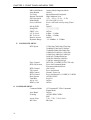
1.1 Description
• The Network Series Modem are high performance,
synchronous and asynchronous, full duplex multi-standard modems designed for
use on 2-wire dial circuits and 2/4 wire leased lines.
The MODEM series fully comply with ITU-T V.34、V.32bis/V.32、 V.22bis、
V.22、V.23、V.21 and BELL 212A/103,speed: 115200 - 300bps Asynch,
33600 - 1200bps Synchronization。
In V.34 and V.32bis/ V.32 modes, echo concellation provides 2-wire full
duplex operation over all PSTN circuits including those with satellite sections.
Compatibility is also provided with Bell 212A and Bell 103 operating standard.
• V.34 mode provide full duplex operation at up to 33.6 kbps speed, with line
probing, symbol rate and carrier frequency selection technologies.
• V.34 mode also use other advance technologies such as Adaptive Precoding, NonLinear Encoding (Warping), Constellation Expansion, Multidimensional Trellis
coding and Shell Mapping ,Tx power back off(Power Reduction).
• There are 10 factory default profiles and 10 user's profiles for your easiest
configuration setting.
• Allow up to 16 modem cards with 16 port on a rack shelf (TRS-16).
• Allow up to 16 modem cards, with 32 port on a rock shelf (TRS-32).
• A 2 by 16 characters LCD display on the front panel with back lighted control for
configuration set-up and monitoring conveniently.
• Line status monitoring including transmit/receive signal level, S/N ratio, EQM (eye
quality monitoring), signal quality, frequency shift, delay, echo, retrain count,
phase jitter, Tx/Rx baud rate, Tx/Rx carrier frequency, Tx/Rx DCE speed, TX
power back-off ..., etc.
• Front panel lock and password protect features prevents from the operation of
unauthorized person.
• Enable remote configuration through secondary channel.
• V.13& V.23 simulated carrier control for half duplex application.
• 2 wires or 4wires automatic or manual dial back-up and restore.
2
CHAPTER 1: MODEM INTRODUCTION
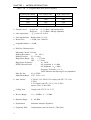
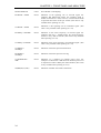
1.2 Technical Specifications
Modem
fully complies with ITU-T recommendations V.34, V.32bis, V.32,
V.22bis, V.22, V.21, V.23, V.24, V.26bis,V.28, V.25, V.25bis, V.52, V.54, V.42,
V.42bis, V.8, and BELL 212A/103 operating standards.
• Modulation type : Refer to table 1-1A,1-1B.
• Clock tolerance
(1) Synchronous : ± 0.01%
(2) Asynchronous : Basic range + 1% to - 2.5%
Extended overspeed range + 2.3% to - 2.5%
• DTE speed
(1) Synchronous :
(2) Asynchronous
33600/31200/28800/26400/24000/21600/19200/16800
/14400/12000/9600/7200/4800/2400/1200 bps
:
115200/76800/57600/38400/33600/32000/31200/28800/
26400/24000/21600/19200/16800/14400/12000/9600/7200
/4800/3600/2400/1200/600/300 bps with speed conversion.
Total bit length : 8, 9, 10, 11 bits
Parity bit
: odd, even, none
Stop bit
: 1, 1.5, 2 bits
: MNP 4/ITU-T V.42
• Error Correction
• Data Compression : MNP 5/ITU-T V.42bis
• Flow Control
: HArdware
CTS/RTS, CTS only
Software
X-ON/X-OFF
• Dial Command : Extended AT and ITU-T V.25bis command set.
3
CHAPTER 1: MODEM INTRODUCTION
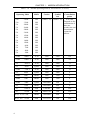
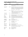
Table 1-1A : Modem operating mode (4 wires/2wires L-L or D-L)
Operating Mode
MOD.
Carrier
Symbol
rate
Constellation
points
(Table 1-1c)
(Table 1-1c)
4 to 1024
Depends on the
combination of
data rate,
symbol rate and
constellation
expansion
chosen.
V.34+
V.34+
V.34
V.34
V.34
V.34
V.34
V.34
V.34
V.34
V.34
33600
31200
28800
26400
24000
21600
19200
16800
14400
12000
9600
SM
SM
SM
SM
SM
SM
SM
SM
SM
SM
SM
V.34
V.34
V.34
7200
4800
2400
SM
SM
SM
V.32bis
14400 T
TCM
1800
2400
128
V.32bis
12000 T
TCM
1800
2400
64
V.32
9600 T
TCM
1800
2400
32
V.32
9600
QAM
1800
2400
16
V.32bis
7200 T
TCM
1800
2400
16
V.32
4800
QAM
1800
2400
4
V.26bis
2400
DPSK
1800
1200
4
V.26bis
1200
DPSK
1800
1200
4
V.22bis
2400
QAM
1200/2400
600
16
V.22
1200
DPSK
1200/2400
600
4
V.23
1200/75
FSK
1700/420
1200
N/A
V.21
0-300
FSK
1080/1750
300
N/A
DPSK
1200/2400
600
4
FSK
1175/2125
300
N/A
BELL 212A 1200
BELL 103
4
0-300
CHAPTER 1: MODEM INTRODUCTION
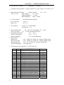
Table 1-1B : V.34 Symbol Rate and Carrier Frequency
Symbol Rate (Baud)
Low Carrier (Hz)
High Carrier (Hz)
2400
1600
1800
3000
1800
2000
3200
1829
1920
3429
1959
1959
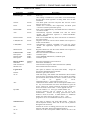
• Transmit Level
Lease-Line: 0~-31 dBm 1 dB stepadjustable.
Dial-Line:
0~-15 dBm 1 dB step adjustable.
• Line requirement : 4/2 wires L-L or D-L
• Line Impedenance : Balance 600Ω ± 10 %
• Return Loss
:> 20 dB, 300 - 3400 Hz
• Longitude Balance :> 60 dB
• Dial Line Characteristics:
Maximum Current :120 mA
Holding Resistance :
50 ~ 220 Ω
Holding Current : 25 ~ 110 mA
Ring Detect Range : ON - > 27 Vrms
OFF - < 13 Vrms
Ring Detect Frequency
:
16 - 50 Hz
DTMF Characteristics
:
O/P Lowband -8 ± 1 dBm
O/P Highband -6 ± 1 dBm
Frequency Tolerance ≤ ± 1 %
TONE Duration and Spacing 95 ms (adjustable)
Pulse Per Sec
: 10 ± 0.5 PPS
Make/Break Ratio : 33/67, 39/61 ± 3 %
• Auto Answer
: V.32bis/V.32/V.22bis/V.22 comply with ITU-T V.25 &
V.25bis
V.34 Comply with ITU-T V.8, V.25/V.25bis
Answer Tone : 2100±15Hz
• Calling Tone
: Comply with ITU-T V.8, V.25
• Receive Range
: -12 ~ -44 dBm, -2 ~ -35 dBm
• Dynamic Range
: 0 ~ -44 dBm
• Equalization
: Automatic Adaptive Equalizer
• Frequency Shift
: Compensation cancel at least of ± 7Hz offset
5
CHAPTER 1: MODEM INTRODUCTION
• Far-end Echo Coverage
:
Maximum 1.2 seconds.
• Scrambler & Descrambler : Comply with ITU-T V.34,V.32bis,V.32,V.22bis, V.22
Output Voltage
• Data And Control Signal :
± (6 ~ 12)V
(ITU-T V.28)
Input Voltage
± (3 ~ 25)V
Output Impedance ≧ 330 Ω
Input Impedance
3000 ~ 7000 Ω
• Tx Clock Source
Freq. Tolerance
Duty Cycle
• Test Features
: Internal/External/Loopback
: ± 0.01 %
: 50 ± 1 %
: V.54/V.52 , LAL/DL/RDL
Test Patterns - 511
90 ~ 265 VAC Auto Range, 47 ~ 63 Hz
• Power Requirement :
DC Power Input : -36 ~ -72 VDC option(Chassis type)
Operating
Temperature :
0 °C ~ 50 °C
•
Storage Temperature
:
-25 °C ~ 70 °C
Relative Humidity
:
95 % (non-condensing)
:
• Physical Size
Stand alone
Ö W - 180mm, H - 48mm, D - 262mm, Weight 0.9kg
Rack mount card
Ö W - 220mm, H - 26mm, D - 328mm, Weight 0.6kg
Rack mount shelf
Ö W - 19", H - 6RU, D - 380mm, Weight 8kg
Full shelf Equipped Ö Weight 16kg
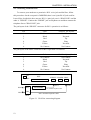
• DTE Interface: EIA RS-232C, CCITT V.24/V.28
Pin
1
2
3
4
5
6
7
8
9
10
15
17
18
20
21
22
24
25
6
V.24
101
103
104
105
106
107
102
109
114
115
141
108
140
125
113
142
DESCRIPTION
(PG) Protective Ground
(TXD) Transmit Data
(RXD) Receive Data
(RTS) Request To Send
(CTS) Clear To Send
(DSR) Data Set Ready
(SG) Signal Ground
(DCD) Data Carrier Detect
+12 VDC
-12 VDC
(TXC)Transmit Clock
(RXC) Receive Clock
(AL) Local Analog Loopback
(DTR) Data Terminal Ready
(RDL) Remote Digital Loopback
(RING) Ring Detect
(XTC) External Clock
(TST) Test Mode
Source
—
DTE
MODEM
DTE
MODEM
MODEM
—
MODEM
MODEM
MODEM
MODEM
MODEM
DTE
DTE
DTE
MODEM
DTE
MODEM
CHAPTER 1: MODEM INTRODUCTION
7
CHAPTER 2: INSTALLATION
CHAPTER 2
INSTALLATION
2.1 Description
2.2 Unpacking
2.3 Site Requirements
2.4 Site Selection
2.5 AC Electrical Outlet Connection
2.6 Connecting With Dial Line
2.7 Connecting With Leased Line
9
CHAPTER 2: INSTALLATION
CHAPTER 2: INSTALLATION
2.1 Description
This chapter provides the information needed to install the Network
Series Modem and to ensure that it is working properly. You may obtain more
information about this subject for rack-mount modem shelf from the User's Manual of
TRS16 or TRS32 rack-mount modem shelf.
2.2 Unpacking
Save the carton and protective packing material in which your Network
Series Modem was shipped; you might need them for repackaging if you have to store
or ship the modem in the future. The following items are shipped with your modem:
* One Modem User's Manual.
* One 7-feet (2.13m) modular telephone cable for connection to RJ45 8-pin
jack.or one site is RJ-45 and the other site is Utype(option).
* One 7-feet (2.13m) modular telephone cable for connection to an RJ11 4-pin
jack.
* One 8-pin RJ-45 box for leased line application.
* One 6-feet power cord.
Rough handling during shipping causes most early modem failure; after you
unpack the modem, check carefully for shipping damage. Contact the shipper if you
notice any damage. Direct any additional questions about damaged or missing parts to
the nearest sales representative.
2.3 Site Requirements
The FCC requires telecommunications equipment to withstand electrical surges
which may result from lightning strikes; the Network Series Modem meet
the requirements set forth by the FCC. Make sure the electrical service in your
building is properly grounded as described in article 250 of the National Electrical
Code (NEC) handbook. The following procedure outlines some common practices
which can minimize the risk of damage to computer equipment from electrical surges:
* Verify that a good copper wire of the appropriate gauge, as described in Tables
250-94/95 of the NEC Handbook, is permanently connected between the
electrical service panel in the building and a proper grounding device such as:
1) A ground rod buried outside the building at least 8 feet (2.44 meters) deep in the
earth. Several ground rods, connected together, buried outside the building at
least 8 feet (2.44 meters) deep in the earth.
10
CHAPTER 2: INSTALLATION
2) If you are unsure whether the electrical service in your building is properly
grounded, have it examined by your municipal electrical inspector.
3) Install a surge protector between the modem and AC power outlet. Any
additional computer equipment you have connected to the modem (directly or
through another device), such as a terminal or printer, should also be plugged
into the same surge protector. Make sure that the surge protector is properly rated
for the devices you have connected to it.
4) Call your telephone company and ask them if your telephone line is equipped
with a circuit surge protector.
5) If you are operating the modem in an area where the risk of electrical surges form
lightning is high, disconnect the modem form the telephone line at the modem's
rear panel when it is not in use.
2.4 Site Selection
Locate the Network Series Modem no farther than 50 feet (15.24 meters)
from your data terminal equipment (DTE) and within 6 feet (1.83 meters) of a
grounded AC outlet furnishing the required power. Install the modem in a clean area
that is free from environmental extremes. Allow at least 6 inch (15.24 cm) in front of
the modem for access to the front panel, and at least 4 inch (10.2 cm) in back for cable
clearance. Position the modem so you can easily see the front panel. Do not stack
another modem on top of modem.
For more detailed information on installation Modem Shelf TRS-16 and NMC16 installation, please refer the Rack-Mounted Modem Shelf - TRS-16 or
TRS-32 User’s Manual”.
2.5 AC Electrical Outlet Connection
The power line associated with MODEM is about 2 meters, three pins plug.
Middle cylinder is for grounding. For power source adapting, an automatic switching
power supply (90 〜265VAC) is used for the device, the fuse for stand alone type is
2A, for rack-mount type is 4A. The rack-mount type is also capable for DC Source
Power Supply (option) and its voltage range is -36 ~ -72VDC.
11
CHAPTER 2: INSTALLATION
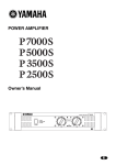
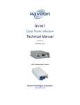
2.6 Connecting With Dial Line
To connect your modem to a permissive RJ11 voice jack and dial line, follow
this procedure: On the rear panel of MODEM, there is an 8 pins RJ-45 jack used for
Leased Line, beside this, there are two RJ-11 6 pins jack, one is “DIAL LINE“ and the
other is "PHONE". Connect the “PHONE” jack to telephone set and then connect the
telephone line to "DIAL LINE" jack.
The pin layout of the “PHONE” connector for RJ11 operation is as follows:
Pin.
Color
“PHONE”pin defined
1
2
3
4
5
6
No Connect
Black
Red
Green
Yellow
No Connect
No Connect
Not used
Tip
Ring
Not used
No Connect
The pin layout of the DIAL connector for RJ11 operation is as follows:
Pin.
Color
“Dial Line”pin defined
1
2
3
4
5
6
No Connect
Black
Red
Green
Yellow
No Connect
No Connect
Not used
Tip
Ring
Not used
No Connect
ON
OFF
DTE
PHONE LEASED DIAL
RJ11
DIAL
RED
LINE
GRN
BOX
TELEPHONE
RJ11 modular telephone cable
RJ11 modular telephone cable
Figure 2-1 Dial Line connecting diagram
12
RJ11
CHAPTER 2: INSTALLATION
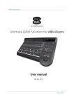
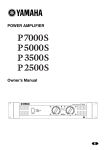
2.7 Connecting With Leased Line
For the leased line connection, you should connect the lines RJ45 connector
labeled with "Leased" on the back of Modem:
Modem
Color
2-Wire
4-Wire
Pin No.
Leased
Line
1
Blue
TX/RX
TX
2
Orange
TX/RX
TX
3
Black
4
Red
TX/RX
TX
5
Green
TX/RX
TX
6
Yellow
RX
7
Brown
RX
RX
8
White (or Gray)
RX
When it used RJ-45 8 core wire, pin 1, 2 is a group used for 2 wires leased line
application. it is TX for 4 wires leased line application. Pin 7,8 is another group, it is
no used in 2 wire leased line application, it is RX for 4 wires leased line application.
When it used RJ-11 4 core wire, pin 4, 5 is TX/RX for 2 wire leased line
application. If it is 4 wires leased line, the pin 4, 5 is TX, pin 3, 6 is RX.
When you connect two modems in "back-to-back" style, don't forget to
interchange TX and RX lines.
A-TX Ö B-RX, A-RX Ö B-TX
ON
OFF
Leased
Line
DTE
TX/2W
BLU
TX/2W
RX
ORG
BWN
RX
WTE
PHONE
LEASED
DIAL
RJ11
RJ45
RJ45 modular
telephone cable
Back-up Line
( If use dial back-up
feature )
BOX
or
Leased
Line
RX
BLK
TX/2W
TX/2W
RED
GRN
RX
YEW
BOX
Figure 2-2 Leased Line connecting diagram
13
CHAPTER 3 : FRONT PANEL AND MENU TREE
CHAPTER3
FRONT PANEL AND MENU TREE
3.1 The Front Panel Description
3.2 The Rear Panel Description
3.3 Operating the Network Series Modem
3.4 The Menu Tree
3.5 Detailed Description of the Menu Tree
15
CHAPTER 3 : FRONT PANEL AND MENU TREE
CHAPTER 3 : FRONT PANEL AND MENU TREE
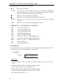
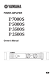
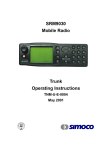
3.1 The Front Panel Description
There are 5 key on the front panel of Modem (VO/DA Key, Right Key,
Left Key, ENTER Key and EXIT Key), one 2 x 16 LCD displayer and 10 LEDs.
Through these interfaces, users are able to see the status of modem or chang the
configurations as illustrated below:
Figure 3-1 Front Panel
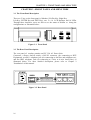
3.2 The Rear Panel Description
The rear panel of modem contains an IEC 320 AC Power Inlet
Connector, a Power On/Off switch, a RS-232 connector (for connecting to DTE
Equipment), two RJ11 telephone jack (for connecting to dial line and telephone set),
and one RJ45 telephone jack (for connecting to 2-wire or 4-wire leased line), as
illustrated below. For more detailed description, please refer to Chapter 2
"Installation" of this manual.
Figure 3-2 Rear Panel
16
CHAPTER 3 : FRONT PANEL AND MENU TREE
3.3 Operating the Network Series Modem
Total 5 keys, as follow:
1. Key :
VO/DA
It is used as the voice/data select key for dial line application,
Disconnect/Reconnect selection for leased line applications, or "home"
key for set-up menu to go back to the home menu.
Left key ; It is used to shift to left field.
Right key; It is used to shift to right field or next item.
ENTER
Enter key; It is used to enter the next lower level menu or confirm
selections.
EXIT
Exit key; use it to go back to the upper level menu.
2. LED indicator : total 10 indicators as following:
PWR
DTR
DSR
RTS
CTS
TXD
DCD
RXD
OH
TST
-----------
On for power supply ok.
On for DTR signal present.
On for DSR signal present.
On for RTS signal present.
On for CTS signal present.
On for "0", off for "1" TXD signal present.
On for received carrier signal (DCD) present.
On for "0", off for "1", RXD signal present..
On for Off Hook.
On for test mode active.
3. LCD displayer :
The modem has a 2 by 16 characters LCD with auto backlight control. Some
different pictures of the LCD display are shown below.
A. Top Menu
Example:
V34+ 336 V42bis
D ANS CONNECT 9
Description:
1) Modem Protocol: V34+ 336,V34+ 312,V34 288, V32b 144T, V32 96T, V22b
24,....
2) Data Protocol: V.42bis, V.42, MNP-5, Normal, Direct.
3) Line Type: D (Dial Line), L (Leased Line).
4) Mode: ANS (Answer Mode) ,ORG (Originate Mode).
5) Status: Stanby, Handshaking, Connect, Retrain, Ring...
6) SQ: Signal quality 9,8,7,6....,0
17
CHAPTER 3 : FRONT PANEL AND MENU TREE
B. Menu Select
Exp 1 :
Exp 2 :
L MENU Select
STATUS
L MENU Select
TEST
Description:
1) In top menu, press "ENTER" key to enter this menu.
2) Select "LOCAL"or "REMOTE" first if connected and remote access function
enabled.
3) The character "L" on the upper left corner stands for local.
4) You may use " " and " " keys to select menu.
5) Press "ENTER " key to enter the "MENU".
6) Press "EXIT" key to quit from this menu.
7) Note that status menu is not available before connection.
C. Menu Screen
Exp 1 :
Exp 2 :
L STATUS
RX Level =-10dBm
Exp 3 :
L TEST
LAL
R CONFIG MODEM
TX clock
Exp 4 :
(ON)
L DIAL
Dial a number
Description:
1)
2)
3)
4)
L=Local, R=Remote.
Menu name: STATUS, TEST, DIAL.......
Status or setting: RX Level=-10dBm, LAL = ON
Use " " or " " keys to shift among fields; press "ENTER" key to enter the
selected menu.
D. Set-up Menu
Exp 1 :
LL TX Level
-10dBm
Exp 2 :
←
R Protocol type
Auto MNP/V42 ←
1) Use " " or " " keys to shift among fields, then press "ENTER" key to confirm
and wait for ← appears on the LCD screen.
2) Press "EXIT" key to quit from this menu.
18
CHAPTER 3 : FRONT PANEL AND MENU TREE
3.4 The Menu Tree
Main Menu
STATUS
DIAL
PROTOCOL
Version
Top
TEST
CONFIG MODEM
CONFIG DTE
COMMAND
LINE SETUP
PROFILE
REMOTE STATUS
A. STATUS MENU / REMOTE STATUS MENU
Tx Level
= -XX dBm
Rx Level
= -XX dBm
S/N. Ratio
= XX dB
EQM Valueio = XXX
F-Shift
= X.X Hz
F F-Shift
= X.X Hz
* Delay
= XXXX ms
* P jitter
= X Deg.
STATUS :
* F Echo
= XX.X dB
DTE
= XXXXX ASY 10
Retrains
= XXXXX
*/ RX Speed
= XXXX
*/ TX Speed
= XXXX
*/ RX Baud
= XXXX
*/ TX Baud
= XXXX
*/ RX Freq
= XXXX Hz
*/ TX Freq
= XXXX Hz
*/ TX PowerOff = X dB
Menu Retrain
Interface indicators = TR MR RS CS CD T
Note:
19
The function with asterisk mark (*) is only available for V.32 and above.
The function with both (*) and (/) marks is only available for V.34.
CHAPTER 3 : FRONT PANEL AND MENU TREE
B. DIAL MENU
Dial a Number
Edit a Number
Ring Times
Progress Tone
Redial Delay
Dial Type
SPK. Control
dial\Off
SPK. Volume
C. PROTOCOL MENU
Protocol Type
#0 nnnn\#1 nnnn\...\#9 nnnn
#0 nnnn\#1 nnnn\...\#9 nnnn
Auto ANS Off\1 Times...255 Times
Basic Code\Don't Care\Dial Tone
\Busy Tone\Dial+Busy Tone
Immediate\1\... \255 Second
Tone\Pulse
Until DCD on\Always on\Off when
Low\Medium\High
Compress
Normal\ Direct\Reliant MNP \Auto
\Reliant LAPM\ LAPM Normal
\LAPM MNP\ MNP Normal
Immediate\With Clear-down \Modem
Reset
Disable\ #0..#9\ ALL\ By NMS
Off\ #0..#9
#0..#9
Disable\ 1…255 Seconds
DTE Speed\DCE/EC/DTE Speed
\DCE Speed
Off\On
Clear All
LAL
DL
RDL
RDL Grant
Error Count
B.E.R. Test
Has Been Done
Off\On
Off\On
Off\On
Off\On
0 ... 65535
Off\511
Discon. Method
Login Check
Send Password
CallBack No.
CallBack Timer
Connect Code
D. TEST MENU
E. CONFIG MODEM MENU
Modem Speed
20
V.34 Adaptive\V34+ 336\V34+ 312
\V34 288\V34 264 \V34 240\V34 216
\V34 192\V34 168\V34 144 \V34 120
\V34 96\V34 72\V34 48\V34 24
\V32b Adaptive\V32b 144\V32b 120
\V32 96Q\V32 96T\V32b 72\V32 48
\V26b 24\V26b 12\ V23 1200
\V22b 2400\V22 1200\BELL 212A
\BELL 103 \V21 300
CHAPTER 3 : FRONT PANEL AND MENU TREE
ORG/ANS Mode
Auto Retrain
Tx Clock
Retrain Threshold
ASI Overspeed
Make/Break
Force Off Hook
OH by DTR
Pump Edit
FB\FF Ctrl
LL Tx Level
DL Tx Level
Remote Access
Dynamic Range
F. CONFIG DTE MENU
DTE Speed
Flow Control
DTR Off Action
DTR Control
TS Control
DSR Control
DCD Control
Data Format
Total Bits
AL by 141
RDL by 140
G. COMMAND MENU
Command Mode
Auto Baud
Framing
Async Form
Idle Char
21
Answer Mode\Originate Mode
On\Off
Internal\External\Loopback
High \Medium \Low
+1%…-2.5% \ +2.3%…-2.5%
US (39%)\UK (33.3%)
Force a off hook activity using "Enter"
key
On\Off
□□□:□□□□
Off\On
0 dBm...-31 dBm
0 dBm...-15 dBm
On\Off
-12..-44dBm\ -2..-35dBm
115200 bps\76800 bps\57600 bps
\38400bps\33600 bps\31200bps
\32000bps\28800 bps\26400 bps
\24000 bps\21600 bps \19200 bps
\16800 bps\14400 bps\12000 bps
\9600 bps\7200bps\4800 bps
\3600 bps\2400 bps\1800 bps
\1200 bps \600 bps\300 bps
Off\X-On, X-Off\RTS/CTS\CTS only
Force On\Command Mode
\Disconnect\Modem Reset
108-2\108-1
Force On\Normal
Normal \ Force On
Force On\Normal\V.13 HDX\V.23 HDX
ASYNC\SYNC
8\9\10\11
Off\On
Off\On
AT Command\V.25bis Command
\Dumb Mode
Off\On
ASYNC\HDLC\SDLC
\BSC
7-O-1 \7-E-1 \7-N-2 \8-N-1
Idle\Sync
CHAPTER 3 : FRONT PANEL AND MENU TREE
H. LINE SETUP MENU
Line Type
Leased To Dial
Backup Tel
Backup Speed
Dial To Leased
Dial \2W Leased Line\4W Leased Line
Manual\Auto
No Dial Backup\#0nnnn\#1nnnn
\…\#9nnnn
V34 Adaptive\V34+ 336\V34+ 312\V34 288
\V34 264\V34 240\V34 216\V34 192
\V34 168\V34 144\V34 120\V34 96
\V34 72\V34 48\V34 24\V32b Adaptive
\V32b 144\V32b 120\V32 96Q\V32 96T
\V32b 72\V32 48\V26b 2400\V26b 1200
\V23 1200\V22b 2400\V22 1200
\BELL 212A\BELL 103\V21 300
Manul\Auto
Dial To Leased Timer Forver\0~255 Minutes
Dial to Dail
I. PROFILE MENU
Load
Power Up
Initial
Front Lock
Password Edit
Sreg Edit
Save
22
Off\On
User Profiles#0...#9
\0:AS-DL-AT-AUTO
\1:AS-DL-AT-NONE
\2:SY-DL-V25-NONE
\3:AS-2L-ANS-V34
\4:AS-2L-ORG-V34
\5:SY-2L-ANS-V34
\6:SY-2L-ORG-V34
\7:SY-4L-ANS-V34
\8:SY-4L-ORG-V34
\9:AS-2L-ANS-AUTO
User Profile #0…#9
Are You Sure?
Unlock\Lock
Input:--BASE=DECIMAL\BINARY
User Profiles#0...#9
CHAPTER 3 : FRONT PANEL AND MENU TREE
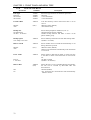
3.5 Detailed Description of the Menu Tree
3.5.1
STATUS MENU
Item Name
Command
Description
TX LEVEL = -XX
dBm
AT%S
Transmitted signal level. This value is equal to the " TX level"
of config modem. Normally, for the 2w leased line and the dial
line, the recommended value is between -10 and -13dBm. It
can be increased of in order to obtain a more satisfactory S/N
ratio (signal to noise ratio) by setting a higher level as possible,
but a saturation of the active transmission equipment should be
avoided. The Tx level level should be setting under -13dBm
while to operating V.34 mode.
RX LEVEL= -XX dBm
AT%S
Received signal level. This value is the result of the line
attenuation from the transmitted signal. Normally, the RX level
of 2w leased line and the dial line is between -15 and -33dBm.
S/N. RATIO = XX dB
AT%S
Signal to noise ratio. The bigger the S/N ratio, the better
quality of a line is. A higher operating speed needs a higher
S/N ratio. Normally, the S/N requirement of running 14400
bps should be more than 24 dB while to operate at 9600 bps,
a S/N better than 20 dB is required.
EQM VALUE=XXX
AT%S
Eye pattern quality monitoring. This value represent the quality
of receiving signal.
F-SHIFT = XX Hz
AT%S
Frequency-shift (offset). It is the shift of the carrier central
frequency caused by the transmission link. This shift normally
should be less than + / - 7 Hz. The smaller is better.
F F-SHIFT = XX Hz
AT%S
Far end frequency-shift (offset). The frequency shift of the far
end received carrier signal. It normally should be less than +/7 Hz. The smaller is better. The value will not accurate once
level is too small from the remote site.
DELAY = XXXX ms
AT%S
Round trip delay time. This delay is caused by a round trip of a
long distance line , especially in a satellite circuit. Usually,
round trip of a satellite link shall create a time delay of 0.5
second (500ms). The modem will accept a maximum time
delay of 1.2 seconds.
P JITTER = -X Deg
AT%S
Monitoring the phase jitter of the phone line.
F ECHO = -XX.X dB
AT%S
Far end echo. This echo is caused when the far end line
impedance is not matched. A smallest far end echo level is
always required. Normally,the far end echo level is between 20 dB and -55 dB
DTE = XXXXX ASY
10
AT%S
Indication of speed and data format of DTE. For examples:
DTE = 19200 ASY 10 stands for 19200 bps Asynchronous 10
bits in total bit length. DTE=14400 SYN means 14400 bps
synchronous.
RETRAINS = XXXX
AT%S
Total retrain count. From the total retrain count, you will find
the total times of line interference occurred. This value will not
be cleared automatically unless pressing the "ENTER" key or
power off.
23
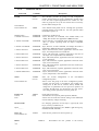
CHAPTER 3 : FRONT PANEL AND MENU TREE
MANU RETRAIN
ATO2
Force Modem redo adapting.
RX BAUD = XXXX
AT%S
Indication of the signaling rate of received signal. For
examples: RX Baud=3429 means the switching speed or
number of transitions is 3429, however, one baud can be made
to represent more than one bit per second. (This value is only
available when operating on V.34)
TX BAUD = XXXX
AT%S
Indication of the signaling rate of transmitted signal. (This
value is only available when operating on V.34).
RX FREQ = XXXXHz
AT%S
Indication of the carrier frequency of received signal. For
examples: RX Freq = 1959Hz means the unique frequency
used to to "carry" data is 1959 Hz. (This value is only available
when operating on V.34).
TX FREQ = XXXXHz
AT%S
Indication of the carrier frequency of transmitted signal. (This
value is only available when operating on V.34).
TX SPEED =
XXXXbps
AT%S
Indication of the DCE speed of transmission.
RX SPEED =
XXXXbps
AT%S
Indication of the DCE speed of receiving.
TX POWEROFF =
XdB
AT%S
Indication of a reduction of transmit power level. For
examples: TX PowerOff = 6dB means the transmit power level
is requested to reduce 6 dB by the remote modem. (This value
is only available when operating on V.34).
TR,MR,RS,CS,CD,T
AT%S
Indication of the RS-232 interface lead status.
24
CHAPTER 3 : FRONT PANEL AND MENU TREE
3.5.2
Item Name
DIAL MENU
Command
Description
Dial a Number
\#0...#9
ATDSn
Dial out a preset telephone number #n(n=0..9). This function
can interact with the auto redial function or dial line auto
establishment function.
Edit a Number
\#0...#9
AT&Zn=xx
Edit telephone number #n (n=0..9) for up to 20 digits each
group.If the "@" is included inside the number and auto-redial
is ON, then it will redial next number after no answer until the
number without "@". If it is still unsuccessful then retirn to the
first number. Up to 10 intelligent redial group is allowed. #1
xxx@ →#2 xxx@ ... →#n xxx →#1 xxx@ →...
Ring Times
ATS0=n
Auto Ans Off
1..255 Times
ATS0=0
Auto answer activates when detected ring count = n
(default=1).
**If 108.1 (DTR ON Auto Dial/Ans) is used for auto answer,
it must be set to OFF and the answer shall be activated by
DTR provided by DTE (default value=1 times).
/Turn off the auto answer function.
/An auto answer will be given when bell rings 1..255 times.
Progress Tone
ATXn
Basic
Don't Care
Dial Tone
Busy Tone
Dial+Busy Tone
ATX0
ATX1
ATX2
ATX3
ATX4
Redial Delay
Immediately
1..255 seconds
Dial Type
Tone
Pulse
ATS37=n
ATS37=0
ATS37=n
ATT
ATP
Enable detecting of busy tone or dial tone to proceed dialing
and showing the connection
/Don't care any tone and do not show line connection speed.
/Don't care any tone and show the line connection speed.
/Don't detect busy tone but show the line connection speed.
/Don't care dial tone but show the line connection speed.
/Do care dial tone, busy tone and show the extended result
code (default).
Pause time between auto redial
/Redial Immediately
/Set up redial time ( /Default=2 second)
Select dial type
/Tone (DTMF) dialing mode
/Pulse dialing mode
SPK.Control
Off
Until DCD On
Always On
Off When Dial
ATMn
ATM0
ATM1
ATM2
ATM3
Monitoring speaker switch control.
/Keep speaker always off
/Speaker turn on until DCD ON,then turn off (default).
/Keep speaker always on.
/Turn on speaker after dialing is completed, and then detect
until to find out carrier and then turn off speaker.
SPK. Volume
Low
Medium
High
ATLn
ATL0
ATL1
ATL2
Speaker volume control.
/Set speaker volume to low.
/Set to medium (default).
/Set to high..
25
CHAPTER 3 : FRONT PANEL AND MENU TREE
3.5.3
Item Name
PROTOCOL MENU
Command
Protocol Type
AT\Nn
Normal
AT\N0
Direct
AT\N1
Reliant MNP
AT\N2
Auto
AT\N3
Reliant LAPM
AT\N4
LAPM,Normal
AT\N5
LAPM,MNP
AT\N6
MNP Normal
AT\N7
Connect Code
DTE Speed
DTE/EC/DCE
DCE Speed
ATWn
ATW0
ATW1
ATW2
Discon. method
Immediate
With clear-down
Modem reset
ATS28=n
(bit3,2)
Login Check
Disable
#0..#9
ALL
By NMS
Send Password
Off
#0..#9
26
Description
Select error correction and data compression function for async
mode only.
*This setting is ineffective in sync mode. It will automatically
become direct mode regardless of setting made once the link
established.
/with DTE speed conversion only.Note that the flow control
function must be active.
/disable error correction, data compression, and DTE speed
conversion.(modem speed=DTE speed)
/Link con be established only when MNP function is enabled on
the remote modem.
/Automatically negotiate V42/MNP level with the remote
modem. The negotiation sequence is V42bis-V42-MNP5MNP4-NORMAL.
/Link can be established only when V42 function is enabled on
the remote modem.
/Negotiate V42 level with the remote modem. The sequence is
V42bis-V42-NOMAL.
\/Automatically negotiate V42/MNP level with the remote
modem. The negotiation sequence is V42bis-V42-MNP5MNP4.
Negotiate MNP level with the remote modem. The sequence is
MNP5-MNP4-NORMAL.
Select the extended CONNECT result code.
/with DTE speed
/with CARRIER, PROTOCOL, and DTE speed
/with DCE speed
Disconnect method for V34/V32bis/V32
/Disconnect immediately.
/Send clear-down sequence before disconnection (default)
/Reset modem after disconnection
(this option is effective only under ANS mode). Assign the
password to authenticate dial-in modem:
/Disable Login Check function.
/With this setting, ANS modem will authenticate dial-in modem
with one of the stored phone number #0..#9, timeout for waiting
password from dial-in modem is about 8 seconds; Control code
‘+’
can
be
applied
in
#0..#9.
(information about ‘+’ is described in section 4.17).
/Authenticate dial-in modem with all stored phone number #0 to
#9. Any successful match will force ANS modem to grant the
access, timeout for waiting password from dial-in modem is
about 8 seconds; Control come ‘+’ can be applied in #0..#9.
/If ANS modem is a card type modelV3600Ui, the
received password will be relayed to CS V1.5x for
authentication. Timeout for waiting password from dial-in
modem is about 8 seconds. If ANS mdoem is a standalone
model, this option will be the same as ‘ALL’. (The
program CS V1.5x is an additional software on CS server)
(this option is effective only under ORG mode). Assign the
stored telephone number, which will be sent out as password
during dial-out connection:
/Disable the action of sending password, this also disables the
function of Dynamic Password assignment function.
/Send one of the stored phone number between #0..#9 as the
CHAPTER 3 : FRONT PANEL AND MENU TREE
password. Time required for sending password is about 2
seconds; Control code ‘+’ can be applied in #0..#9.
(Call back telephone number). Assign one of the stored phone
number #0..#9 as the Call Back Number. Control codes such as
‘+’, ‘<’, ‘>’ should not appear in phone number.
CallBack No.
#0..#9
The period ANS modem will delay before start Call Back
procedure (from Idle to Dial). When this option is set to
‘Disable’, all Call Back related function will also be disabled
(including Dynamic Callback assignment function).
CallBack Timer
Disable
1…255 Seconds
Compress
Off
At%Cn
AT%C0
On
AT%C1
3.5.4
Item Name
Control of the data compression function
/disable data compression function
(use V42 or MNP4 error correction only)
/enable data compression function
(use V42bis or MNP5 data compression in addition
to V42 or MNP4 error correction)
TEST MENU
Command
Description
Clear All
AT&T0
Clear all the tests in one time, and a statement "Has been done"
shall be shown.
LAL
ON
OFF
AT&T1
Local analog loop test (ON/OFF).This test is normally used to
certify if the modem is in normal operation condition. Also,
this test is usually carried out together with B.E.R test.
RDL
ON
OFF
AT&T6
For remote digital loop test (ON/OFF). This test can control
remote modem to executive digital loop for BER test to find
out if the modem and line of both ends are in normal condition.
DL
ON
OFF
AT&T3
For digital loop test (ON/OFF). This test enable the received
digital data demodulated and send back to match with the far
end test.
RDL Grant
ON
OFF
AT&T4
AT&T5
Bit error count display function. Press Left or Right shift key to
insert error. Press "ENTER" key to clear.
Error Count
0..65535
B.E.R Test
OFF
511
27
Set for accepting remote digital loop(RDL) test.
/Enable. (default)
/Disable.
AT&T10
Set bit error rate test function.
/Disable (default).
/use the 511 test pattern
CHAPTER 3 : FRONT PANEL AND MENU TREE
3.5.5
Item Name
Speed
V34
Command
Description
AT%Bn
Set modem speed and protocol.
AT%B0
V34+
336
V34+
312
V34
288
V34
264
V34
240
V34
216
V34
192
V34
168
V34
144
V34
120
V34
96
V34
72
V34
48
V34
24
V32b Adapt
AT%B42
AT%B41
AT%B28
AT%B37
AT%B27
AT%B36
AT%B26
AT%B35
AT%B34
AT%B38
AT%B33
AT%B32
AT%B31
AT%B40
AT%B47
V32b
144
V32b
120
V32
96Q
V32
96T
V32b
72T
V32
48
V26b
2400
V26b
1200
V23
1200
V22b 2400
V22
1200
V21
300
BELL
212A
BELL
103
AT%B20
AT%B19
AT%B18
AT%B17
AT%B16
AT%B15
AT%B9
AT%B8
AT%B7
AT%B5
AT%B3
AT%B1
AT%B4
AT%B2
/Set modem speed to be V.34 adaptive (multi-standard hand-shaking)
mode, connectable speed from V.34 / V.32b / V.32 / V.22bis / V.22
/V.21. Only work for Dial Line.
/Set modem speed to V34 + 33.6k bps....4DTCM(SM)
/Set modem speed to V34 + 31.2k bps....4DTCM(SM)
/Set modem speed to V34 28800 bps....4DTCM(SM)
/Set modem speed to V34 26400 bps....4DTCM(SM)
/Set modem speed to V34 24000 bps....4DTCM(SM)
/Set modem speed to V34 21600 bps....4DTCM(SM)
/Set modem speed to V34 19200 bps....4DTCM(SM)
/Set modem speed to V34 16800 bps....4DTCM(SM)
/Set modem speed to V34 14400 bps....4DTCM(SM)
/Set modem speed to V34 12000 bps....4DTCM(SM)
/Set modem speed to V34 9600 bps....4DTCM(SM)
/Set modem speed to V34 7200 bps....4DTCM(SM)
/Set modem speed to V34 4800 bps....4DTCM(SM)
/Set modem speed to V34 2400 bps....4DTCM(SM)
/Set modem speed to V.32 Auto, auto detact V.32b /V.32 /V.22bis /
V.22 /V.21
/ Set modem speed to V.32bis 14400 bps TCM
/ Set modem speed to V.32bis 12000 bps TCM
/ Set modem speed to V.32 9600 bps QAM
/ Set modem speed to V.32 9600 bps TCM
/ Set modem speed to V.32bis 7200 bps TCM
/ Set modem speed to V.32 4800 bps QAM
/ Set modem speed to V.26 2400 bps DPSK
/ Set modem speed to V.26 1200 bps DPSK
/ Set modem speed to V.23 1200 bps FSK
/ Set modem speed to V.22bis 2400 bps QAM.
/ Set modem speed to V.22 1200 bps DPSK
/ Set modem speed to V.21 300 bps FSK
/ Set modem speed to BELL 212A 1200bps DPSK
/ Set modem speed to BELL 103 300 bps FSK
ORG/ANS
Mode
ATS14=n
Set modem as the originate or answer mode.
Originate Mode
Answer Mode
(bit7)
/Originate site
/Answer site
Auto Retrain
AT%En
On
Off
AT%E1
AT%E0
The automatic adaptive equalizer can be re-adjusted via retrain
procedure activated automatically when the S/N become worse than
the preset threshold.
/Retrain occurs automatically according to SQ/EQM value. (default)
/Auto retrain disable.
Tx Clock
AT&Xn
Select transmit clock source.
Internal
External
AT&X0
AT&X1
Loopback
AT&X2
/Internal clock source, for most point to point application (default).
/External clock source, for cascade and TDM/STDM network
application.
/Received clock source, for used in slave side of polling networks or
the modem in the most far end of a cascading network.
28
Adapt
CONFIG MODEM MENU
CHAPTER 3 : FRONT PANEL AND MENU TREE
LL TX Level
ATS30=n
0..-31 dBm
DL TX Level
Set leased line transmit level.
/-13dBm (default)
ATS56 =n
0..-15 dBm
Set dial line transmit Level.
/-13dBm (default)
ASI Overspeed
AT%An
Select async data speed tolerance.(ITU-T V.14)
+1%
+2.3%
Make/Break
AT%A0
AT%A1
AT&Pn
/Basic range +1% to -2.5% (default).
/Extended overspeed range +2.3% to -2.5%.
Pulse dial make / break ratio selection.
UK(33.3%)
US(39%)
AT&P1
AT&P0
/33.3\66.7% (default).
/39\61%.
Force OFF Hook
ATH1
Force modem off-hooking the line to busy out the in
coming calls.
OH by DTR
ATS19=n
(bit 6)
Make the modem to off-hook the line when DTR being
off for a period of time
/enable the OH By DTR function
/disable the OH By DTR function (default)
ATS57=n
(bit1,0)
High
Medium
Low
Select the scaleable retrain threshold for determining the
data rate of the connection.
/Issue a retrain or rate change in normal line condition
/Issue a retrain or rate change in poor line condition
/Issue a retrain or rate change in worse line condition
Pump Edit
product designer use only.
On
Off
RTRN.Threshold
FB/FF CTRL
AT%Gn
Auto speed fallback and fall forward
On
Off
AT%G1
AT%G2
/Enable (Dial Line Default)
/Disable (Leased Line Default)
Remote Access
ATS27=n
(bit3)
Enable the modem to monitor and control the remote
modem through the secondary channel
/enable remote access function
/disable remote access function (default)
ATS28=n
(bit0)
Select the dynamic range of receiving signal.
On
Off
Dynamic Range
-12..-44dBm
-2 ..-35 dBm
29
/-12 to -44 dBm (Default)
/-2 to -35 dBm
CHAPTER 3 : FRONT PANEL AND MENU TREE
3.5.6
CONFIG DTE MENU
Item Name
DTE Speed
Command
AT
300 bps
Description
This setting is used to determine DTE speed when auto
speed conversion is ON in V.42 / MNP / normal mode.
*When using direct mode and all the synchronous
modes, this setting will not available and DTE speed
will be determined by modem speed, DTE speed =
modem speed.
600 bps
1200 bps
1800 bps
2400 bps
*The throughput is improved by using data
compression, enhance this set higher than the modem
speed is suggested to enable more effective operation.
3600 bps
4800 bps
7200 bps
*When use "AT" command and auto baud rate detect
function "ON", this setting will be replaced by
identified speed.
9600 bps
12000 bps
*The Auto baud rate function can detect all the listed
DTE speed.
14400 bps
16800 bps
19200 bps
/Default = 57600 bps.
21600 bps
24000 bps
26400 bps
28800 bps
31200 bps
33600 bps
38400 bps
57600 bps
76800 bps
115200 bps
Flow Control
AT\Qn
Off
X-ON/X-OFF
CTS Only
AT\Q0
AT\Q1
AT\Q2
RTS/CTS
AT\Q3
DTR CTL
108-2
108-1
AT%Dn
AT%D0
AT%D1
Modem action select for DTR from OFF to ON.
/Same as V.25 108.2 DTR operation (default).
/Same as V.25/V.25bis 108.1 DTR operation. When
DTR is from OFF to ON,the modems will dial the
designed preset telephone number or answer according
to the current ring count.
DTR Off Action
AT&Dn
Forced On
AT&D0
Command mode
AT&D1
On originate and answer site respectively modem action
select for DTR from ON to OFF.
/Force DTR in ON position
A power-on auto dial operation can be achieved when
operating with DTR ON auto dial (default).
/Return to the command mode.
30
Used to set flow control between terminal and modem
when using V.42/MNP and normal mode (asynchronous
mode only).
/No flow control
/Software control, used in text data.
/Hardware control identical to RTS/CTS control, but
modem send the data in spite of RTS from DTE,
unilateral control.
/Hardware control, bilateral, accept any type of data
(default).
CHAPTER 3 : FRONT PANEL AND MENU TREE
Disconnect
MODEM Reset
AT&D2
AT&D3
/Disconnect. Normally used with 108.1.
/Force Modem reset.
DSR Control
Normal
Forced on
AT&Sn
AT&S1
AT&S0
DSR signal control selection.
/DSR ON after Modem handshaking.
/Force DSR in ON position.
DCD Control
Forced on
Normal
AT&Cn
AT&C0
AT&C1
V.13 HDX
AT&C2
V.23 HDX
AT&C2
DCD signal control selection.
/Force DCD in ON position.
/DCD ON means line is in connection while DCD OFF
means line is OFF (default).
/ITU-T V.13 standard simulated carrier in half-duplex
mode.
/ITU-T V.23 standard simulated carrier in half-duplex
mode.
RTS Control
Normal
Forced on
AT&Rn
AT&R0
AT&R1
RTS signal control selection.
/Controlled by RTS.
/Keep RTS in ON position..
Data Format
Async
Sync
AT&Mn
AT&M0
AT&M1
Data format selection in data mode.
/Async.
/Sync.
Total bits
ATS19=n
(bit5,4)
Total bit length for async data format
(including Start, Stop, Parity, Data bits, default =10)
ATS23=n
(bit2)
DTE control AL through EIA RS-232 pin18
8/9/10/11
AL by 141
On
Off
RDL by 140
On
Off
31
/Enable
/Disable (default)
ATS23=n
(bit1)
DTE control RDL through EIA RS-232 pin21
/Enable
/Disable (default)
CHAPTER 3 : FRONT PANEL AND MENU TREE
3.5.7
COMMAND MENU
Item Name
Command Mode
AT command
Command
ATS19=n
(bit1.0)
V.25bis command
Dumb mode
Description
Intelligent function command set selection.
/Hayes compatible "AT" command set with async
format.
/ITU-T V.25bis command set with async, Bisync and
HDLC\SDLC formats.
/Dumb mode, don't accept any command. This mode is
set for all leased line and most of the sync dial line to
prevent modem from interference made by the data of
the terminal, and protect the terminal against any
malfunction caused by the return result code from the
modem.
Auto Baud
AT%Un
On
Off
AT%U1
AT%U0
Framing
ASYNC
HDLC/SDLC
BSC
ATS19=n
(bit1,0)
V.25bis command data format.
/Async (default).
\HDLC/SDLC
\Bisync/monosync
Async form
ATS19=n
(bit5,4)
Select the Async data parity
7-O-1
7-E-1
7-N-2
8-N-1
Idle char.
Idle
SYNC
32
Auto baud rate detection function control for AT
command mode.
/Enable (default).
/Disable.
/7 Data Bits, odd parity 1 stop bit
/7 Data Bits, even parity 1 stop bit
/7 Data Bits, none parity 2 stop bits
/8 Data Bits, none parity 1 stop bit (default)
ATS19=n
(bit3)
Select the char to be transmitted for the BSC & HDLC
faming
/No character to be Tx when idle.
/SYNC char be Tx when idle.
CHAPTER 3 : FRONT PANEL AND MENU TREE
3.5.8
LINE SETUP MENU
Item Name
Command
Description
Line Type
Dial Line
2W Leased
4W Leased
AT&Ln
AT&L0
AT&L1
AT&L2
Select line type and also set dial back-up function.
/Dial line.
/2 wire leased line.
/4 wire leased line.
Leased to Dial
ATS31=n
Manual
Auto
(bit0)
Auto dial back-up control while leased line is out of
service.
\Manual control (default)
/Auto dial back-up.
Backup Tel.
No dial backup
#0 nnnn .. to #9 nnnn
Select backup telephone number #n (n=0~9)
/Disable backup function (default)
/Enable backup function and make a choice of the
phone number group.
Backup Speed
V34 Adapt to V21 300
ATS55=n
Select modem speed used in the auto dial backup mode.
\(default =V.34 288)
Dial To Leased
ATS31=n
Manual
Auto
(bit1)
Select whether return to leased line automatically or not
during dial back-up mode.
/Manual control (default)
/Return to the leased line automatically when leased line
is recovered.
D to L Timer
ATS36=n
When operate in dial back-up mode, to select how long
it will take to detect if the leased line is recovered or
not.
/No dial to leased
\(default = 60 minutes)
ATS42=n
( bit 3 )
When dial line is in use (excluding dial back-up mode),
the line can be restored by auto-redial after line
disconnection.
/Disable (default)
/Any abnormal line disconnection shall automatically
redial to connect.
Forever
1..255 mins.
Dial To Dial
Off
On
33
CHAPTER 3 : FRONT PANEL AND MENU TREE
3.5.9
PROFILE MENU
Item Name
LOAD
Command
ATZn
Description
This machine provides 20 groups of load configuration
profile. Among them 10 groups configuration profile which
cover the most required applications for normal use. The
other 10 groups are set by the user which can be revised by
the user before filing for use.
(n=0-9)
User Defined :
User Profile#0..#9
AT&Zn
/User defined load profile #0..#9. Through this operation,
required settings can be made for the next operation when
the modem is power on.
Default profile :
0: AS-DL-AT-AUTO
AT&Fn&W
AT&F0&W
1: AS-DL-AT-NONE
AT&F1&W
2: SY-DL-V25-NONE
AT&F2&W
3: AS-2L-ANS-V34
AT&F3&W
4: AS-2L-ORG-V34
AT&F4&W
5: SY-2L-ANS-V34
AT&F5&W
6: SY-2L-ORG-V34
AT&F6&W
7: SY-4L-ANS-V34
AT&F7&W
8: SY-4L-ORG-V34
AT&F8&W
9: ASY-2L-ANS-AUTO
AT&F9&W
Load factory profile #0..#9.
/Async, dial line, AT command, Auto reliable mode, V34
Adapt, this mode is most applicable to BBS networks.
/Async, dial line, AT command, direct mode and V34 Adapt,
this is a typical operating mode for Hayes compatible
modem
/Sync, dial line, V.25bis command, V34 Adapt, this mode is
applicable to IBM AS-400 series sync dial networks.
/Async, 2W leased line, answer, applicable to the most of the
async, non-compressed 2 wire leased line.
/Async, 2W leased line, originate, applicable to the most of
the Async, non-compressed 2 wire leased line.
/Sync, 2W leased, answer, applicable to the most of the Sync,
2 wire leased line.
/Sync, 2W leased line, originate, applicable to the most of the
Sync, 2 wire leased line.
/Sync, 4W leased, answer, applicable to the most of the Sync,
4 wire leased line.
/Sync, 4W leased line, originate, applicable to the most of the
Sync, 4 wire leased line.
/Async, 2W leased line, answer, applicable to the most of the
async, compressed, 2 wire leased line.
SAVE
AT&Wn
(n=0-9)
Store the revised configuration in the user-defined
configuration profile.
\/Store in the nth group in the user's configuration profile.
Usually, the 0th group is provided for the working area,
setting store in this area or load the factory default will
change the set parameters for next power-on operation. If
you want the nth group is to be used for the next poweron working profile, operate the load user profile #n.
ATS29=n
(bit4)
Front panel lock control.
/No limitation for any front panel operation (default).
/Allow view the status and current setting of the modem,but
can not make any changes of setting.
User Profile#0..#9
Front Lock
Unlock
Lock
Password edit
For changing password, use left key-L, right key-R, enter
key-E, exit key-X, Home key-V.
/The password by the factory are "REEE" (right moving key,
ENTER, ENTER, ENTER).
Input:_ _ _ _
Power up
User Profile#0..#9
Initial
34
AT&Yn
select the user profile to be used on power up.
AT&F10
Re-initialize the user profiles to the Factory
CHAPTER 3 : FRONT PANEL AND MENU TREE
profile#0,and flush the stored telephone numbers.
/confirm the initializing action. Press enter key to
confirm or any other key to quit.
Are you sure???
Serg edit
Base = DEC
Base = Bin
XX : △△△□□□□□□□□
ATSn=m
Edit the contain of the selected sreg.
/Edit the value of the S-register in decimal form.
/Edit the value of the S-register in binary form.
After selecting the form, press Enter to starting
editing S-register shown in the following format.
xx: Use left key,right key and enter key to select
the S-register to be edited.
∆∆∆: Use left key, right key and enter key to edit
the value of the selected S-register in decimal
form.
: Use lift, right, and enter key to
edit the value of the selected S-register in binary
form.
To discard editing, press exit key.
35
CHAPTER 4: GENERAL INFORMATION AND FEATURES
CHAPTER 4
GENERAL INFORMATION AND FEATURES
CONTENT
4.1
4.2
4.3
4.4
4.5
4.6
4.7
4.8
4.9
4.10
4.11
4.12
4.13
4.14
4.15
4.16
4.17
4.18
4.19
37
Preview
Dieal Line VS. Leased Line
2W/4W Leased Line
Originate Mode VS. Answer Mode
Synchronous VS. Asynchronous
Error Correction And Data Compression
Configuration Profile Set-up
Remote Access
Multi-standard Handshake
Auto Dial Back-Up
Auto Fallback And Fall Forward
Line Status Monitoring
B.E.R. Test
Intelligent Dial
Front Panel Lock And Password Protect
ITU-T V.13/ V.23 Simulated Carrier Control in Half Duplex
Password and Call Back Functions
Intelligent Dial Polling
G3 Fax Send/Receive
CHAPTER 4: GENERAL INFORMATION AND FEATURES
CHAPTER 4: GENERAL INFORMATION AND FEATURES
4.1 Preview
In order to help you to get familiar with your Network Series Modem, this
chapter introduces you some common applications. For most applications, the
materials of this chapter will be enough.
4.2 Dial Line VS. Leased Line
There are two kinds of telephone lines --- dial lines and leased lines described as
below.
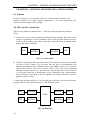
A. Leased line provides users a dedicated communication channel. Both ends of the
circuit are permanent. It offers continuous service and provides absolute security.
It will not be invaded by any other circuit due to the dedication, it supports better
quality and higher reliability.
DTE
MODEM
∼
MODEM
DTE
FIG. 4-1: Leased Line
B. B. Before using a dial line such as the circuits for telephone and facsimile machine,
we have to dial a number. For the users who are used to communicate with
different counterparts such as bulletin board system (BBS), public service network,
and toll free services, this will be a better choice. Due to the time consuming
dialing procedure (45-60) Sec.), the efficiency is lower than that of leased lines. It
is even worse when line or destination is busy. Furthermore, the communication
path is different at each dial, so the line quality is not ensured. Besides, it doesn’t
guarantee good security.
To make this modem operate in 2/4-wire leased line, or dial line, you need to do some
settings with Line Type Selection under “LINE SETUP” menu.
DTE
MODEM
MODEM
DTE
MODEM
DTE
PSDN
DTE
MODEM
FIG 4-2: Dial Line
38
CHAPTER 4: GENERAL INFORMATION AND FEATURES
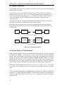
4.3 2W/4W Leased Line
We had talked modem operate in the previous section. There are two-wire leased lined
and four-wire leased line.
2W leased line achieves full duplex with only a pair of lines. There comes up the
problem of interference. In V.21, V.22, V.22bis operating modes, the Modem used
the frequency split method. Whereas, in V.32/V32bis/V.34 mode, it must provides
"echo cancellation", because originate and answer modems occupy the same
frequency band.
4W leased line offers two independently unilateral transmission channel, therefore, it
can achieve full duplex communication with less interference.
Obviously, the line quality of 4W leased line is better than that of 2W leased line.
However, the modem does an excellent job with both 2W and 4W leased lines and
even dial line.
DTE
MODEM
∼
MODEM
DTE
2W Leased Line
DTE
MODEM
∼
∼
MODEM
DTE
4W Leased Line
FIG. 4-3: 2W/4W leased line.
4.4 Answer Mode VS. Originate Mode
While using the dial line, there must be a modem initiating the call, once the exchange
recognizes the number, it connects the circuit to the answering modem with ring
signals. Answering modem can pick up the call manually or automatically. Afterward,
it issues the answer tone to connect with the originate modem. Usually, we call the
modem which dials the call as originate mode and the other one as answer mode.
According to the role of the connection the training sequence and working frequency
band of either modem is different from each other even operating with leased line.
With 2/4-wire full-duplex operation such as V.21, V.22, V.22bis, V.23, V.32, V.32bis,
V.34, Bell 103, and Bell 212A, there should be an originate mode and an answer
mode.
You may find the information of originate/answer settings in the “ORG/ANS MODE”
column of “CONGIF MODEM” MENU. Note that the modem will automatically
determine either mode whenever you use the “AT” commands, front panel dialing, or
auto answering.
39
CHAPTER 4: GENERAL INFORMATION AND FEATURES
4.5 Synchronous VS. Asynchronous
The data formats of both connecting modems must be exactly the same in order to
exchange data with each other.
There are synchronous and asynchronous data formats. The common personal
computers and terminals are asynchronous. Whereas, the host computers and their
terminals are often synchronous.
For most multiplexes, the connecting modems should be synchronous. However, the
user should know the type of the data terminal equipment (DTE) to get proper
operation.
Except V.21, V.23, and Bell 103 which only can operate in asynchronous mode, other
protocols can run in either mode.
About the settings of this issue, you may find it at “Data Format” column of
“CONFIG DTE” menu. Note that if the asynchronous mode is selected, you need to
set “Data Bits”, “DTE Speed”, as well. On the other hand, if you operate the modem
with “AT” command, it will automatically determine these parameters.
4.6 Error Correction And Data Compression
The Network Series Modem supports “Error Correction” and “Data
Compression” while operating in asynchronous mode. In addition to 100% error free,
it also provides two to four times data compression rate to increase throughput.
MNP class 4 provides error corrections. MNP class 5 provides data compression for
up to two times. On the other hand, V.42 and V.42bis are the recommendations from
ITU-T V.42 to provide error correction and V.42bis provides data compression for up
to four times.
Due to the improved throughput, the modem it provides DTE speed up to 115200 bps
for between data terminal and modem.
During connecting, the modem automatically recognizes the protocol being used by
the remote modem and set the priority order as LAPM with EC→LAPM→MNP-5→
MNP-4→NORMAL.
Under these error correction and data compression operations, there should be some
kinds of flow control between modem and data terminal equipment (DTE) to avoid
data loss. the hardware solution to the modem is by controlling RTS and CTS signals.
The software solution is by utilizing X-on and X-off codes.
To find the setting information dealing with error correction and data compression,
you may look up the “PROTOCOL” menu. In addition, “CONFIG DTE” menu gives
you the guide to flow control setting.
40
CHAPTER 4: GENERAL INFORMATION AND FEATURES
4.7 Configuration Profile Set-Up
The Network Series Modem have various operating modes. To save your
energy, it provides 10 sets of factory default settings as well as 10 sets of user setup
profile which store data even the power is off. Users may choose the most similar
factory default setting; make some modifications with front panel or by AT commands
from terminal then save the modified setting to a user profile. From then on, once the
modem is turned on, it will use this user profile as default.
You may find the “Load”, ”Save” selections in the “PROFILE” Menu where you can
save the current configuration into the selected user profile or load the user or the
factory profile.
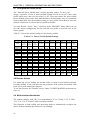
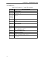
Table 4.7.1 shows the default settings of each factory profiles.
Table 4.7.1 Factory Profile Default Settings
Profile #
SETTING
ITEM
#0
#1
#2
#3
#4
#5
#6
#7
#8
#9
ASY-DL- ASY-DL- SYN-DL- ASY-2L- ASY-2L- SYN-2L- SYN-2L- SYN-4L- SYN-4L- ASY-2LANS-V34 ORG-V34 ANS-V34 ORG-V34 ANS-V34 ORG-V34 ANSV25ATATAuto
NONE
NONE
AUTO
ASYNC ASYNC
SYNC
ASYNC ASYNC
SYNC
SYNC
SYNC
SYNC
ASYNC
DATA
FORMAT
COMMAND
AT
AT
LINE Type
DIAL
DIAL
RING Times
1
1
MODEM
V.34
V.34
SPD
Adapt
Adapt
ORG/ANS
ANS
ANS
Tx level
-13dBm -13dBm
Auto Retrain
On
On
DTE Speed
57600
57600
PROTOCOL V42bis
Direct
FLOW
RTS/CTS Xon/Xoff
CTRL.
RTS CTRL.
ON
ON
DCD CTRL Normal
ON
DTR OFF
ON
ON
DSR CTRL.
ON
ON
Disconnect
clear
immediate
Method
down
V25bis
DIAL
1
V.34
Adapt
ANS
-13dBm
On
57600
Direct
Off
Normal
Normal
DISCNT
Normal
clear
down
DUMB
DUMB
DUMB
DUMB
DUMB
DUMB
DUMB
2WL.L
2WL.L
2WL.L
2WL.L
4WL.L
4WL.L
2WL.L
1
1
1
1
1
1
1
V.34 288 V.34 288 V.34 288 V.34 288 V.34 288 V.34 288 V.34 288
ANS
-13dBm
On
57600
Direct
Off
ORG
-13dBm
On
57600
Direct
Off
ANS
-13dBm
On
57600
Direct
Off
ORG
-13dBm
On
57600
Direct
Off
ANS
-13dBm
On
57600
Direct
Off
ORG
ANS
-13dBm -13dBm
On
On
57600
57600
Direct
V42 bis
Off
RTS/CTS
ON
Normal
ON
ON
clear
down
ON
Normal
ON
ON
clear
down
Normal
Normal
ON
ON
clear
down
Normal
Normal
ON
ON
clear
down
Normal
Normal
ON
ON
clear
down
Normal
Normal
ON
ON
clear
down
Normal
Normal
ON
ON
clear
down
4.8 Remote Access
For improving service loading, the modem offers a remote access function through
secondry channel. It can read and write the parameter of the remote site modem from
local site for well maintenance purpose.
To use this function, the "Remote Access" under "CONFIG MODEM" menu must set
to be on.
4.9 Multi-standard Handshake
The modem complys with ITU-T recommendations V.34, V.32bis, V.32, V.22bis,
V.22, V.21, V.8, V.42 and V.42bis operating standard.
This functions in both calling and answering mode to automatically recognize the
remote modem standard and connect to it accordingly.
41
CHAPTER 4: GENERAL INFORMATION AND FEATURES
4.10 Auto Dial Back-Up
When you apply the modem to leased lines, no matter what protocol you are using, in
case that the lines don't function well, you may allow modem dial a stored number via
a dial line to rebuild the connection. This line is called "back-up line."
While using the back-up line, the modem periodically checks the recovery of leased
lines to find the opportunity to go back to leased lines in order to save the charge of
dial line.
To use this function, you must set "leased To Dial" and "Dial To Leased" to be
"AUTO" or "MANUAL" under "LINE SETUP" menu; also fill up "Backup Tel#1"
and recovery time.
4.11 Auto Fallback And Fall Forward
When auto fallback & fall forward is enabled in V.34 or V.32bis mode, the modem
will automatically initial a V.34 or V.32bis rate renegotiation when the line condition
changes, so that the optimum available data rate is always select with minimal
interruption to user data.
To use this function, the "FF/FB control " under "CONFIG MODEM"menu must set
to be on.
4.12 Line Status Monitoring
In order to let users manage transmission conditions, the Network Series
Modem provides a signal quality displayed at right lower corner of the screen. It
ranges from 0 to 9. The following shows the relationship between the displayed
number and bit error rate (BER).
9
8
7
6
5
4
3
2
1
0
-----------
< 10 ^ -9
< 10 ^ -8
< 10 ^ -7
< 10 ^ -6
< 10 ^ -5
< 10 ^ -4
< 10 ^ -3
< 10 ^ -2
< 10 ^ -1
NO Connect
Basically, 10^-5 to 10^-6 is the basic required bit error rate. If this condition is not
achievable; leased line users should report to telephone company, however, it is better
for dial line users to try the dial again.
There are some real time line condition information which may help you judge the
line quality:
Examples :
1. Transmitted signal level
Tx level = -10 dBm
2. Received signal level
Rx level = -25 dBm
3. Signal to noise ratio
S/N Ratio = 35 dB
4. Received frequency shift
F-Shift = 0.2 Hz
5. Far-end frequency shift
F F-Shift = 1.7 Hz
6. Round trip delay
Delay = 560 ms
42
CHAPTER 4: GENERAL INFORMATION AND FEATURES
7. Phase jitter
P J = 1 Degree
8. Far-end echo level
F Echo = -40 dB
9. Terminal mode
DTE = 19200 ASY 10
10 .Retrain count
Retrains = 1
The parameters above can be found in “STATUS” menu.
4.13 B.E.R Test
In addition to the parameters stated in the previous section, the Network
Series Modem also offers bit error rate test without any extra test instruments.
Before using the BER test, you have to build a connection then enter "TEST"
menu, set "BER Test" to be ON, select "Error count". Note that if you want to do this
test with both modems, you need to do the setting described above with both modems.
During test, you may press "→" or "←" key to send some error codes and observe
whether the other modem received them or not. The number of error bits for each
issue is from 2 to 5. At the beginning of the test, you may press “ENTER” to clear
"Error Count. " Wait a period, you may get B.E.R by dividing error count by total
transmitted bits. There are one test pattern, say 511, you may choose from. The
selection can be done at "BER TEST" under "Test" menu. Note that the settings of
both modems should be consistent.
You may execute this test even no one is at the remote site. It can be done by utilizing
remote digital loopback (RDL) which makes remote modem loopback its received
data. To start it, activate “RDL” in “Test” menu, then execute BER test stated above.
Beware that error codes generated by local modem will be received by itself. Hence,
the error count you get is the sum of that of transmitted and received routes (bilateral).
You may judge whether the modem is good or not by operating local analog loopback
then execute BER test. No matter how long you execute this test, the error count
should be 0.
4.14 Intelligent Dial
There are some data terminal equipment such as multiplexes, controllers, and
synchronous terminals can’t issue “AT” commands to dial. The modem offers you a
very convenient way to dial by means of operating front panel. In addition to ten set
phone number, it provides you a 108/1 auto dial function which dial pre-determined
number when you turn the modem on or when DTR is turned on (off to on transition).
4.15 Front Panel Lock and Password Protect
In order to prevent from the operation of unauthorized persons, we offer you this
function. After you set “Front Lock” under “PROFILE” menu to be “Lock”, even the
front panel keys are still effective, all the operations affecting transmission are not
allowed. You only may observe the setting and monitor the line conditions.
To release the lock, you need to enter a password. The following is the table of panel
keys.
"EXIT" --X
"ENTER" --E
"HOME" --V
"Æ"
--R
"Å"
--L
The factory setting is “REEE”, and can be modified by users. Before you change the
password, you need to enter the old one. So don’t forget the password you had entered.
43
CHAPTER 4: GENERAL INFORMATION AND FEATURES
4.16 ITU-T V.13/ V.23 Simulated Carrier Control in Half Duplex
The modem normally operates in full duplex. mode. However, some applications may
requires control of a remote DCD signal by a local RTS signal. V.13/ V.23 operation
allows local RTS control of remote DCD signal without on-off carrier switching in
half duplex operation.
The V.13/ V.23 function apply to the SNA network and the related setting is located
in "DCD control" under "CONFIG DTE" menu.
4.17 PASSWORD AND CALLBACK FUNCTIONS
4.17.1 Dynamic Password/CallBack:
Special Control codes below can be utilized to assign Dynamic Login Password or
Call Back Phone Number (work with both AT command dialing string and front panel
dialing operation):
a. ‘<’ +<string>: Control code for Dynamic Password assignment. <string> after ‘<’
will be sent to ANS modem as Password. It overrides the setting in ‘Send
Password’, but will be ignored if ‘Send Password’ = ‘Off’.
b. ‘>’ +<string>: Control code for Dynamic Call Back Number assignment. <string>
after ‘>’ will be sent to ANS modem as the desired Dial Back Number. After ANS
modem authenticated ORG modem, it will call back with <string>. This Control
code overrides the setting of ‘Call Back No.’ in ORG modem. If ‘Send Password’
= ‘Off’ on ORG modem or ‘Call Back No.’ = ‘Disable’, this character will be
ignored.
4.17.2 Extension Code for Stored Phone Numbers (‘+’+<char>):
If the last two digits of Stored Phone Number is ‘+’+<char>, modem will dial current
number and continue on with specific stored number as designated by <char>. <char>
is the stored phone number order(#n). (any other characters after <chart> will be
omitted)
For example: ATDT1234+5 will force the modem to dial 1234 and the number stored
in #5. Total number in a dial string should not exceed 250 characters. The ‘+’ Code
should not appear in Call Back Number or it will be ignored when ANS modem
calling back.
4.17.3 Additional Information:
a.
b.
c.
d.
44
Front Panel LCD will show “Call Back” to indicate it is under Call Back mode:
When ANS modem is waiting under ‘Call Back Timer’ to call back.
When ORG modem dial with Dynamic Call Back Control Code “>”+<string> and
sending Password for authentication(no matter send with ‘Send Password’ or
Dynamic Password): ANS modem will save received Password, and send it back
while Call Back link was built. And it overrides the setting in its own ‘Send
Password’.
When modem is under Call Back operation, VO/DA can be used to cancel
procedure.
When applying Password or Call back Security function, ‘PROTOCOL’ setting in
both modems should be identical.
CHAPTER 4: GENERAL INFORMATION AND FEATURES
Dynamic Password/Call Back Control Code as “>”, “ <” will not take effect
during Login check (will be treated as part of Password).
There’s no Call Back function under leased line mode.
f. Password Security by Pass through
e.
4.18 Intelligent Dial Polling
1. Settings:
When under Dial Modifiers setting, use “@” symbol for intelligent dial polling
instead, but “=” is still “wait for quiet answer (silence).
2. Operations:
If a “@” symbol included in the Telephone Number #0- #9, also abnormal
disconnection, i.e. jumping back to Idle before connecting occurred (exception:
when Originate user press the VO/DA button), then dialing will be proceeded from
the telephone number with a “@” symbol and stop at the one without a “@” symbol.
For instant: Tel #0: 12345678@
Tel #1: 23456789@
Tel #2: 34567890
If dialing starts from #0, it will automatically dial from #0, #1 to #2 and stops at #2.
Note: if user has set Dial To Dial function to “On”, then the dialing will keep
dialing #2.
Also reminds that:
a. If user is using ATDTxxxx@ command to dial, then it will start the dial polling
from Telephone Number #0.
b. If the setting of DTR is “DTR off to on (108-1)”, then the “@” symbol (function)
needs to be set included in #0 in order to start the dial polling function after the
initial dialing.
c. If the setting is “Dial to Dial on”, then the “@” symbol (function) needs to be set
included in the Backup Tel in order to start the dial polling function after the
initial dialing.
d. If the dial polling number followed by an “Empty” phone number, then the
dialing will cycle back to #0. (However, if the Tel #0 is an empty number, then
the dial polling will terminate.)
e. When dial polling to #9 (or #5 when the Country Code is Beijing it will
return back to #0.
f. When during the “Dial Backup” (Leased to Dial), then the “@” function will not
be working.
g. The dial polling will terminate when a connection has been made.
h. Before the connection, user at Originate can press the VO/DA key to terminate
the dial polling.
45
CHAPTER 5 : INSTRUCTION SETS
CHAPTER 5
INSTRUCTION SETS
CONTENT
5.1 AT Command Set
5.2 Dial Modifiers
5.3 Result Codes
5.4 V.25bis Auto Call Unit
46
CHAPTER 5 : INSTRUCTION SETS
CHAPTER 5 : INSTRUCTION SETS
5.1 AT Command Set
Table 5-1: AT Command Set
Cmd
A/
repeat the last AT command
ATA
answer command
ATD
dial command
ATEn
echo on/off
0 : echo off
1 : echo on
hang on/off
0 : on hook
1 : off hook
modem identification command
0 : report product code
1 : ROM checksum
2 : verify ROM checksum
3 : Report ROM components
4 : modem capabilities and version
5 : Country Code
6 : pump controller : CS
7 : pump-DSP : CS
8 : CTL/ SPX Version
9 : OK
speak volume control
0 : Low
1 : Medium
2 : High
speak control
0 : off
1 : untill DCD on
2 : Always
3 : off when dial
go online
0 : go back to data mode
1 : rate change
2 : retrain
enable pulse dialing
ATHn
ATIn
ATLn
ATMn
ATOn
ATP
47
Function Description
CHAPTER 5 : INSTRUCTION SETS
Cmd
ATQn
ATS
ATT
ATVn
ATWn
ATXn
ATZn
AT&Cn
AT&Dn
AT&Fn
48
Function Description
response on/off
0 : response on
1 : response off
S register read/write
ATSnn? : read s register
ATSnn=mm : write value mm (in decimal form) to the s
register nn
enable tone dialing
result code form (long/short)
0 : short
1 : long
extented result code formats
0 : CONNECT with DTE speed
1 : CONNECT with CARRIER, PROTOCOL and DTE speed
2 : CONNECT with DCE speed
result code formats / call progress options
0 : CONNECT without speed message,
blind dial, no busy tone
1 : CONNECT with speed message,
blind dial, no busy tone
2 : CONNECT with speed message,
wait for dial tone, no busy tone
3 : CONNECT with speed message,
blind dial, check busy tone
4 : CONNECT with speed message,
wait for dial tone, check busy tone
load user profile n (n=0~9)
0 : load user profile 0
n : load user profile n
DCD control
0 : DCD forced on
1 : DCD normal
2 : V.13 HDX
3 : V.23HDX
DTR on-to-off actions
0 : ignore
1 : recall command mode
2 : disconnect
3 : reset modem
load factory profile n
n = 0 .. 9
CHAPTER 5 : INSTRUCTION SETS
Cmd
AT&Gn
AT&Kn
or
AT\Qn
AT&Ln
AT&Mn
or AT&Qn
AT&Pn
AT&Rn
AT&Sn
AT&Tn
AT&Vn
AT&Wn
AT&Xn
49
Function Description
guard tone options
0 : disabled
1 : 550 Hz
2 : 1800 Hz
DTE flow control options
0 : no flow control
1 : XON/XOFF flow control
2 : CTS only flow control
3 : RTS/CTS flow control
line type selections
0 : dial line
1 : 2-wired leased line
2 : 4-wired leased line
data format options
0 : async data mode
1 : sync data mode
dial pulse (MAKE/BREAK) ratio
0 : USA (39/61%)
1 : UK (33/67%)
RTS/CTS options
0 : RTS normal
1 : RTS forced on
DSR control
0 : DSR forced on
1 : DSR on after connect
selftest commands
0 : clear all test
1 : LAL test
3 : DL test
4 : RDL grant enable
5 : RDL grant disable
6 : RDL test
7 : RDL + TP test
8 : LAL + TP test
10 : TP on
view active config/user profiles/tel numbers
0 : view current active profile
n : view user profile n (n=1~9)
save to user profile n
n = 0 to 9
sync tx clock source options
0 : internal clock
1 : external clock
2 : slave (loopback) clock
CHAPTER 5 : INSTRUCTION SETS
Cmd
AT&Yn
AT&Zn
AT\Jn
AT\Nn
AT%An
50
Function Description
powerup user profile n (n=0~9)
0 : load user profile 0 on power up
n : load user profile n on power up
view/store telephone number n (n=0~9)
n = 0 .. 9, the selected telephone number
AT&Zn? : view tel number n
AT&Zn=string : store the string to tel number n.
DTE/DCE speed convert on/off
0 : enable DTE/DCE speed convert
1 : disable DTE/DCE speed convert
protocol type options
0 : normal mode
1 : driret mode
2 : MNP reliable mode
3 : auto-reliable mode
4 : LAPM reliable
5 : LAPM reliable with fallback to normal mode
6 : LAPM reliable with fallback to MNP mode
7 : MNP reliable with fallback to normal mode
async tolerance
0 : basic ASI (+1% to -2.5%)
1 : extended ASI (+2.3% to -2.5%)
CHAPTER 5 : INSTRUCTION SETS
Cmd
AT%Bn
AT%Cn
51
Function Description
modem speed
0 : V.34_Adaptive
1 : V21_300 / FAX 300
2 : B103_300
3 : V22_1200
4 : B212_1200
5 : V22_2400
7 : V23_1200
8 : V26b_1200
9 : V26b_2400
10 : V27_2400
11 : V27_4800
13 : V29_7200
14 : V29_9600
15 : V32_4800
16 : V32b_7200
17 : V32_9600T
18 : V32_9600Q
19 : V32b_12000
20 : V32b_14000
26 : V34_19200
27 : V34_24000
28 : V34_28800
29 : V32t_16800
30 : V32t_19200
31 : V34_4800
32 : V34_7200
33 : V34_9600
34 : V34_14400
35 : V34_16800
36 : V34_21600
37 : V34_26400
38 : V34_12000
40 : V34_2400
41 : V34_31200
42 : V34_33600
43 : V17_7200
44 : V17_9600
45 : V17_12000
46 : V17_14400
47 : V32b_Adaptive
data compression on/off
0 : data compression off
1 : data compression on
CHAPTER 5 : INSTRUCTION SETS
Cmd
AT%Dn
AT-V
DTR off-to-on actions
0 : DTR off-to-on normal (108.2)
1 : DTR off-to-on dial/ans according to ring-in(108.1)
auto retrain control
0 : auto retrain disable
1 : auto retrain enable
display current line status
0 : display local status
1 : display remote status
auto fall forward/fallback enable
0 : auto fall forward/fallback disable
1 : auto fall forward/fall back enable
autobauding on/off
0 : autobauding off
1 : autobauding on
calling tone on/off
0 : calling tone off
1 : calling tone on
display versions
AT-Rn
read DSP ram content (for test only)
AT-Wn=mm
write DSP ram content (for test only)
AT%En
AT%Sn
AT%Gn
AT%Un
AT-Cn
52
Function Description
CHAPTER 5 : INSTRUCTION SETS
5.2 Dial Modifiers
Table 5-2 Dial Modifiers for AT and V25bis command
CODE
'T' or 't'
enable tone dial
'P' or 'p'
enable pulse dial
'0' to '9''
A' to 'D'
'a' to 'd'
'*', '#'
dial digit
','
pause
'!'
flash hook
'W' or 'w'
or ':'
';'
wait for dial tone
return to idle after dial
'@' or '='
wait for quiet answer (silence)
“@” intelligent dial polling
'R' or 'r'
reverse to the answer mode
'Sn' or 'sn'
'+'
'-' or '(' or ')'
or ' '
53
Function Description
dial stored tel number n
cascade the tel number to the next one
do nothing
CHAPTER 5 : INSTRUCTION SETS
5.3 Result Codes
Table 5-3 AT Command Result Codes
Short
54
Long form
0
OK
1
CONNECT
2
RING
3
NO CARRIER
4
ERROR
5
CONNECT 1200
6
NO DIAL TONE
7
BUSY
8
NO ANSWER TONE
9
None
10
CONNECT 300
11
CONNECT 600
12
None
13
CONNECT 1800
14
CONNECT 2400
15
CONNECT 3600
16
CONNECT 4800
17
CONNECT 7200
18
CONNECT 9600
19
CONNECT 12000
20
CONNECT 14400
21
CONNECT 16800
22
CONNECT 19200
23
CONNECT 21600
CHAPTER 5 : INSTRUCTION SETS
Table 5-3 Result Codes (cont.)
Short
55
Long form
24
CONNECT 24000
25
CONNECT 26400
26
CONNECT 28800
27
CONNECT 32000
28
CONNECT 38400
29
CONNECT 57600
30
CONNECT 76800
31
CONNECT 115200
32
CONNECT 31200
33
CONNECT 33600
CHAPTER 5 : INSTRUCTION SETS
5.4 V.25bis Auto call Unit
V.25bis auto call unit is used for auto calling in asynchronous and synchronous data
formats.
1. V.25bis Commands
a. CRNx
b. CRSy
c. PRNy;x
d. RLN
e. CIC
f. DIC
- Call request - dial a phone number (x) entered on DTE keyboard.
- Call request - dial a phone number stored in specified memory
address (y). y=0-9.
- Program number - store a phone number (x) in specified
memory address (y). y=0-9
- Request list of all stored numbers.
- Connect incoming call. Auto answer enable.
- Disregard incoming call. Auto answer disable.
2. V.25bis Responses
a. INC
b. INV
c. VAL
d. LSN
e. CNX
-
Modem detects an incoming call.
Modem received invalid command entry.
Modem received valid command entry.
Modem responses LSN when received RLN command.
Connection.
3. V.25bis Call Failure Responses
a. CFIET
b. CFIAB
c. CFIRT
d. CFICB
e. CFINS
f. CFIND
56
-
Busy tone had been detected
Modem aborted a call.
Ringback timeout.
Modem busy.
No phone number is stored.
No dial tone is detected.
CHAPTER 6 : MAINTENANCE
CHAPTER 6
MAINTENANCE
CONTENT
6.1 Description
6.2 Instruments
6.3 Periodic Maintenance
6.4 Troubleshooting
6.5 Return Procedure
57
CHAPTER 6 : MAINTENANCE
CHAPTER 6 : MAINTENANCE
6.1 Description
This chapter gives you the information of maintenance and the required instruments in
order to let you recover the troubles quickly.
6.2 Instruments
The only instrument you need is a mult-meter, due to the embedded digital and analog
test abilities.
6.3 Periodic Maintenance
For every three months, you should do the following jobs.
(A) Turn the power off, clean the modem, check the plugs, make sure all the
connectors are connected firmly.
(B) Be sure that the indicators function well.
6.4 Troubleshooting
Once the Network Series Modem malfunctions, please check and record the
indicators at the moment then turn the power off. Consequently, make sure the IC's on
printed circuit board are firmly sited. Try to turn the power on again, if the trouble still
exists, please follow the procedures below.
1)
Power Unit
•
•
2)
Make sure you get a proper power source. If no indicator is lighted,
probably the problem is the power unit.
Check the power fuse; if it is broken, replace it.
RS-232 Interface
•
•
Do the AL (local analog loopback) test, feed some data into the modem
and check if they were returned correctly.
Please make sure the interface is connected firmly; also check if the cable
is in good condition.
6.5 Return Procedures
We suggest the individuals who hold a malfunctioned the Network Series
Modem would contact with your local representative or distributor of or just
directly access our customer service department as soon as possible in order not to
cause catastrophe. You may find the contact address and phone number in the cover
sheet of this manual.
58
APPENDIX 1: Modem S-REGISTER TABLE
APPENDIX 1: Modem S-REGISTER TABLE
No
Default
Unit
S0
S1
S2
S3
S4
S5
S6
S7
S8
S9
S10
1
0
43
13
10
8
2
45
2
6
15
times
times
decimal
decimal
decimal
decimal
second
second
second
100ms
1/.1s
S11
S12
S13
95
14
19
ms
100 ms
binary
S14
00001010
binary
No
Default
Unit
59
Function Description
Auto-answer Ring Count
Current Ring Count (read only)
Escape Char
CR Char
LF Char
Backspace Char
Pause Before Blind Dial
Wait for Carrier Time
Pause for Comma
Carrier Validation Time
Lost Carrier Detect Time
( 1 sec unit for V34/V32bis/V32)
(0.1 sec unit for V22bis/V22)
DTMF Tone Duration
Guard Time (Escape Sequence Pause)
Bit-Mapped Options (set/clear)
bit 4,3,2,1,0 - DTE Speed
0 - 300 bps
1 - 600 bps
2 - 1200 bps
3 - 1800 bps
4 - 2400 bps
5 - 3600 bps
6 - 4800 bps
7 - 7200 bps
8 - 9600 bps
9 - 12000 bps
10 - 14400 bps
11 - 16800 bps
12 - 19200 bps
13 - 21600 bps
14 - 2400 bps
15 - 26400 bps
16 - 28800 bps
17 - 32000 bps
18 - 38400 bps
19 - * 57600 bps
20 - 76800 bps
21 - 115200 bps
22 - 31200 bps
23 - 33600 bps
bit 7,6,5
- reserved
Bit Mapped Options(set / clear)
bit 0
*0 - AT-C0
calling tone off
1 - AT-C1
calling tone on
bit 1
0 - ATE0
echo off
*1 - ATE1
echo on
bit 2
*0 - ATQ0
response on
1 - ATQ1
response off
bit 3
0 - ATV0
response code
*1 - ATV1
response word
bit 4
- reserved
bit 5
*0 - ATT
Tone Dial
1 - ATP
Pulse Dial
Function Description
APPENDIX 1: S-REGISTER TABLE
bit 6
bit 7
S15
S16
01000000
binary
S17
S18
S19
0
00011100
minute
binary
S20
S21
00000101
binary
No
Default
Unit
Answer
Originate
reserved
Bit Mapped Options(set / clear)
bit 0
*0 - AT&T0
Test Pattern off
1 - AT&T10,&T7,&T8 Test Pattern on
bit 1
*0 RDL off
1RDL on
bit 2
*0 - AT&T0
LAL off
1 - AT&T1,T8
LAL on
bit 3
0 - AT&T0
LDL off
*1 - AT&T3
LDL on
bit 4
*0 - AT&T0
RDL off
1 - AT&T6,T7
RDL on
bit 5
- reserved
bit 7,6
- test pattern selection
00 - reserved
*01 - AT%T1
511 pattern
10 - reserved
11 - reserved
reserved
Modem Test Timer(minute)
Bit Mapped Options(set/clear)
bit 0,1
- V25bis character framing
*00 - Async
01 - HDLC
10 - BSC
11 - reserved
bit 2
*1 - NRZ / 0 NRZI
bit 3
*1 - flag idle / 0 mark idle
bit 5,4
- word length
00 - 7-bit data, even parity, 1 stop bit
*01 - 8-bit data, no parity, 1 stop bit
10 - 7-bit data, odd parity, 1 stop bit
11 - 7-bit data, no parity, 2 stop bit
bit 6
- DTR off cause busy out /* nothing
bit 7
*0 - V.32bis fast training disable
1 - V.32bis fast training enable
Reserved
Bit Mapped Options
bit 1,0
- DCD control
00 - AT&C0 DCD forced on
*01 - AT&C1 DCD on after connect
10 V.13 HDX
11 V.23 HDX
bit 2
0 - AT&R0 RTS normal
*1 - AT&R1 RTS forced on
bit 4,3
- DTR on-to-off action
*00 - AT&D0
Ignore(force on)
01 - AT&D1
recall command mode
10 - AT&D2
Disconnect
11 - AT&D3
reset modem
bit 5
*0 - CTS off in retrain (CCITT)*
1 - CTS follows RTS (EIA)
Function Description
bit 6
bit 7
60
- reserved
*0 - ATA
1 - ATD
*0 - AT&S0
1 - AT&S1
- reserved
DSR forced on
DSR on after connect
APPENDIX 1: S-REGISTER TABLE
S22
01110110
binary
S23
00100001
binary
No
Default
Unit
S24
01000000
binary
61
Bit Mapped Options
bit 1,0
- speak volume
00 - low
*01 - medium
10 - high
11 - reserved
bit 3,2
- speak control
00 - off
*01 - speaker on until carrier detected
10 - always on
11 - off when dial
bit 6,5,4
- result code and call progress
000 - ATX0 CONNECT without speed
message, blind dial, no busy
tone(Basic Code)
001 - reserved
010 - reserved
011 - reserved
100 - ATX1 CONNECT with speed
message, blind dial, no busy
tone(Dialn Tone)
101 - ATX2 CONNECT with speed
message, wait for dial tone, no busy
tone
110 - ATX3 CONNECT with speed
message, blind dial, check busy
tone(Busy Tone)
*111 - ATX4 CONNECT with speed
message, wait for dial tone, check
busy tone(Dial+Busy Tone)
bit 7
0 - AT&P0 Make/Break ration USA
(39%)
*1 - AT&P1 Make/break ratio UK
(33.3%)
Bit Mapped Options (set / clear)
bit 0
0 - AT&T5 slave RDL disabled
*1 - AT&T4 slave RDL enabled
bit 1
*0
RDL by 140 disable
1
RDL by 140 enable
bit 2
*0
AL by 141 disable
1
AL by 141 enable
bit 3
*0 - AT%A0 basic ASI (-2.5% to +1%)
1 - AT%A1 extended ASI (-2.5% to +2.3%)
bit 5,4
- data length on direct mode
00 - 8 bits (6-N-1)
01 - 9 bits (7-N-1)
*10 - 10 bits (8-N-1)
11 - 11 bits (8-Stuff Parity –1)
bit 7,6
- guard tones
*00 - AT&G0 Disabled
01 - AT&G1 550 Hz
10 - AT&G2 1800 Hz
11 - reserved
Function Description
Bit Mapped Options
bit 1,0
- DTR off-to-on control
*00 - AT%D0 normal (108.2)
01 - AT%D1 dial/ans according to ringin (108.1)
APPENDIX 1: S-REGISTER TABLE
S25
00
100ms
S26
S27
0
00001000
10ms
binary
S28
00000000
binary
No
Default
Unit
S29
10101101
binary
62
10 - reserved
11 - reserved
bit 3,2
- reserved
bit 7-4
- Login check
0000..1001 - #0..#9
1010 - ALL
1011 By NMS
*1100.. 1111 Disable security check
DTR Debounce Time
bit 3,2,1,0
- DTR drop detection time
bit 7,6,5,4
- DTR rising detection time
RTS to CTS Delay
Bit Mapped Options(set /clear)
bit1,0
- data mode data format
*000 - AT&Q0,&M0 async data mode
001 - AT&Q1,&M1 sync data mode
010 - reserved
011 - reserved
bit 2
remote status enable / *disable
bit 3
*remote access on / remote access off
bit 5,4
- sync transmit clock source
*00 - AT&X0 internal clock
01 - AT&X1 external clock
10 - AT&X2 slave (loopback) clock
11 - reserved
bit 7,6
- line type
*00 - AT&L0 dial line
01 - AT&L1 2-wired leased line
10 - AT&L2 4-wired leased line
11 - reserved
Bit Mapped Options
bit 0
1 - -2 to -35 dBm
receive dynamic range
*0 - -12 to -44 dBm
receive dynamic range
bit 1
- reserved
bit 3,2
- disconnect option
*00 - send clear down before disconnect
01 - immediately disconnect
10 - reset modem on disconnect
11 - reserved
bit 5,4
- ENQ/ACK control
*00 - AT\H0 no ENQ/ACK
01 - AT\H1 to host (simulate peripheral)
10 - AT\H2 to peripheral (simulate host)
11 - reserved
bit 6
- fix speed function
bit 7
- reserved
Function Description
Bit Mapped Options
bit 1,0
- command selection
00 - dumb mode
*01 - Hayes AT command mode
10 - V.25bis command mode
11 - reserved
bit 2
0 Line break
*1 Send continuous space
bit 3
0 - AT%E0
auto retrain off
*1 - AT%E1
auto retrain on
bit 4
*0 - front panel unlock
APPENDIX 1: S-REGISTER TABLE
1 - front panel lock
00 - AT%G0
auto FB/FF disable
*01 - AT%G1
auto FB/FF enable
10 - AT%G2
Auto FF off but FB on
11 - reserved
bit 7
0 - AT%U0
autobauding off
*1 - AT%U1
autobauding on
Leased Line Tx Level (0..-31 dBm)
Bit Mapped Options
bit 0
- leased to dial
0 - manual*
1 - auto
bit 1
- dial to leased
0 - manual*
1 - auto
bit 2
- V.32 auto FFFB by Retrain
bit 3
- reserved
bit 7,6,5,4
- backup tel. (#0~9)/no dial backup
- reserved
Test time(minute)
Test time(second)
OH by DTR timer (default 30 seconds)
D to L timer (default 60 mins)
Redial delay, Immediately 1….255 Second
V34 Baud Rate Selection
bit 0
- enable 2400 /disable 2400
bit 1
- reserved (this bit always must be
set)
bit 2
- enable 2800 /disable 2800
bit 3
- enable 3000 /disable 3000
bit 4
- enable 3200 /disable 3200
bit 5
- enable 3429 /disable 3429
Break type during Normal, V.42 or
bit 7,6
MNP operation
00 AT\K0 break -0 (destructive)
01 AT\K1 break -1(nondestructive)
*10 AT\K2 break -2 (queue)
11 - reserved
reserved
Call back time(unit : second)
0 - Disable acll back
1..255 - Second
Bit Mapped Options
bit 1,0
- connect message display
00 - ATW0 CONNECT with DTE
speed
*01 - ATW1 CONNECT with CARRIER,
PROTOCOL and COMPRESSION
10 - ATW2 CONNECT with DCE speed
11 - reserved
bit 2,3,4,5
- reserved
bit 7,6
- DTMF level selection (Low Band /
High Band)
00 -8 / -6 dBm
01 -10 / -8 dBm
10 -12 / -11 dBm
11 -11 / -9 dBm
Function Description
bit 6,5
S30
S31
13
00000000
S32
S33
S34
S35
S36
S37
S38
0
-dBm
binary
30
second
2
00000000
second
binary
S41
00000001
binary
No
Default
Unit
S39
S40
63
APPENDIX 1: S-REGISTER TABLE
S42
00000010
S43
00000000
S44
S45
S46
S47
S48
S49
S50
00000000
S51
00000011
No
Default
binary
Bit Mapped Options
bit 0
reserved
bit 1
0 - receive power drop control off
*1 - receive power drop control on
bit 2
*0 - enable V.34 asymmetrical rate
1 - disable V.34 asymmetrical rate
bit 3
*0 - disable dial to dial
1 - enable dial to dial
bit 7,6,5,4 0000-1010 - Pre-Emphasis Filter Suggestions
Number 0-A
*1011-1111 - Ignore Pre-Emphasis Filter
binary
Fast Connect Control
bit 3,2,1,0
- Answer tone length (100ms time
base.) 0ms-1500ms
bit 4
- Fast connect on/*off (1/*0)
bit 7,6,5
- reserved
Reserved
Reserved
Reserved
Reserved
Reserved
Reserved
binary
Bit Mapped Options
bit 1,0
- FAX/DATA Mode Selection
*00 - (DATA mode)
01 - reserved
10 - reserved
11 - reserved
bit 2
- reserved
bit 7,6,5,4,3
- reserved
binary
Bit Mapped Options
bit 1,0
- flow control
00 - AT\Q0,AT&K0 no flow control
01 - AT\Q1,AT&K1 XON/XOFF flow
control
10 - AT\Q2,AT&K2 CTS only flow
control
*11 - AT\Q3,AT&K3 RTS/CTS flow
control
Unit
Function Description
bit 3,2
S52
64
0
dec
- DTE/DCE speed convert
*00 - AT\J0 enable DTE/DCE speed
convert
01 - AT\J1 disable DTE/DCE speed
convert
10 - reserved
11 - reserved
bit 7,6,5,4
- auto dial telephone number
AT%B Desired Highest DCE Speed
*0 - adaptive baud rate
1 - V21_300
2 - B103_300
3 - V22_1200
4 - B212A_1200
5 - V22b_2400
6 - reserved
7 - V23_1200(1200Tx / 75Rx)
8 - V26b_1200( V26b_1200 )
9 - V26b_2400( V26b_2400 )
APPENDIX 1: S-REGISTER TABLE
S53
00010011
binary
No
Default
Unit
10 - reserved
11 - reserved
13 - reserved
14 - reserved
15 - V32_4800
16 - V32b_7200 TCM
17 - V32_9600 TCM
18 - V32_9600 QAM
19 - V32b_12000T
20 - V32b_14400T
26 - V34_19200
27 - V34_24000
28 - V34_28800
29 - reserved
30 - reserved
31 - V34_4800
32 - V34_7200
33 - V34_9600
34 - V34_14400
35 - V34_16800
36 - V34_21600
37 - V34_26400
38 - V34_12000
40 - V34_2400
41 - V34+_31200
42 - V34+_33600
43 - reserved
44 - reserved
45 - reserved
46 - reserved
47 - V32b_Adaptive
Bit Mapped Options
bit 3,2,1,0
protocol type
0000 - AT\N0 normal mode
0010 - AT\N2 MNP reliable mode
*0011 - AT\N3 auto-reliable mode
0100 - AT\N4 LAPM reliable
Function Description
0101 - AT\N5
S54
S55
S56
S57
65
13
00
-dBm
binary
LAPM reliable with
fallback to normal mode
0110 - AT\N6 LAPM reliable with
fallback to MNP mode
0111 - AT\N7 MNP reliable with
fallback to normal mode
bit 4
0 - AT%C0 data compression off
*1 - AT%C1 data compression on
bit 7,6,5
- reserved
Bit Mapped Options
bit 3,2,1,0
Call back telephone number
0000..1001 - #0..#9
1010…1111 - Off
Bit 3-0, Call back telephone number
bit 7,6,5,4
Send login word
0000..1001 Send security password #0~#9
1010..1111 - reserved
backup speed V.34+ 33600 .. V.21 300
Dial Line Tx Level
Bit Mapped Options
bit 1,0
- retrain threshold
*00 - High
APPENDIX 1: S-REGISTER TABLE
S58
S59
S60
66
0
01 - medium
10 - Low
11 - reserved
bit 2
- reserved
bit 3
Security password pass through
bit 7,6,5,4
- reserved
Retrain times , 0 ~ 255 (default 2 )
Profile Checksum
decimal Power-up # (AT&Yn)
APPENDIX 2: LCD MENU QUICK REFERENCE
APPENDIX 2: LCD MENU QUICK REFERENCE
MENU
I
T
E
M
Version screen
Main Screen
V.34 Modem
V:2.XX/BA/8.050
V34 Adapt V42bis
D ANS Standby
SN: xxxxxxxxxxxx
V:2.XXX/BA/8.050
L TARGET SELECT
LOCAL
L TARGET SELECT
REMOTE
↓
↑
→
# Note 1
=
“ENTER” KEY
=
“EXIT” KEY
=
“>” KEY
← = “<” KEY
Scroll item & parameter by “>” or “<”
Note1: Only available when connected and
Remote Access function is enabled
STATUS
DIAL
PROTOCOL
TEST
CONFIG. MODEM
CONFIG. DTE
COMMAND
LINE SETUP
Tx Level
Dial a Number
Protocol Type
Clear All
Speed
DTE Speed
Command Mode
Line Type
Load
Rx Level
Edit a Number
Discon. Method
LAL
ORG/ANS Mode
Flow Control
Auto Baud
Leased To Dial
Power Up
S/N Ratio
Ring Times
Login Check
DL
Auto Retrain
DTR Off Action
Framing
Backup Tel
Initial
EQM
Progress Tone
Send password
RDL
Tx Clock
DTR Control
Async form
Backup Speed
Front Lock
F-Shift
Redial Delay
Call Back No.
RDL Grant
RTRN. Threshold
RTS Control
Idle Char
Dial to Leased
Password Edit
F F-Shift
Dial Type
Call Back Timer
Error Count
ASI Overspeed
DSR Control
Dial to Leased Timer
Sreg Edit
Delay
SPK Control
Connect Code
B.E.R Test
Make/Break
DCD Control
Dial To Dial
Save
Phase jitter
SPK Volume
Compress
Force Off Hook
Data Format
F Echo
OH By DTR
Total Bits
DTE
Pump edit
AL by 141
Retrains
FB\FF Ctrl
RDL by 140
Menu Retrain
LL Tx Level
RX Baud
DL Tx Level
TX Baud
Remote Access
RX Freq
Dynamic Range
TX Freq
RX Speed
TX Speed
Tx Power Off
Interface indicators
67
Version screen
PROFILE
APPENDIX 3: LCD MENU QUICK REFERENCE
APPENDIX 3: LCD MENU QUICK REFERENCE
↓ =
"ENTER” KEY
↑ =
"EXIT” KEY
→=
“>” KEY
←=
“<” KEY
Card Selection = "CARD#” KEY
Go to the top layer of menu tree = "HOME” KEY
NMC - 16
V5.xx-11 ID=001
↓ ↑
01Select Menu
Modem Control
↓ ↑
01 Secect Menu
3333333333333333
→
←
01Select Menu
Current Alarm
↓ ↑
Stand Alone
Modem Menu
68
01 Alarm Config
Group Setup
↓ ↑
RXL Low
RXL High
SNR Bad
DTR Off
N-Echo High
TXD Inactive
RXD Inactive
Connect Fail
Rmt RXL low
Rmt RXL high
Rmt SNR bad
Rmt DTR off
Rmt N-Echo
No Dial Tone
Dial Backup
Card Fail
→
←
01Select Menu
Ararm Config
01 Select Menu
NMC ID
↓ ↑
01 Current Alarm
No alarm or alarm occur
↓ ↑
V34 Adapt Direct
D ANS Standby
→
←
→ 01 Group Setup
XXXXXXXXXXXXXXXX
←
↓ ↑
→
←
RXL Low
RXL High
SNR Bad
Chk Dial Line
Dial Backup
DTR Off
TD/RD Inactive
N-Echo High
01 NMC ID
001 ~ 253
→
←
01 Select Menu
NMS Speed
↓ ↑
External Clk
2400
4800
7200
9600
12000
14400
16800
19200
21600
24000
26400
28800
31200
33600
36000
38400
40800
43200
45600
48000
50400
52800
55200
57600
→
←
01 Select Menu
NMS Interface
↓ ↑
RS-485 port
RS-232 with CTS
RS-232 no CTS
→
←
01 Select Menu
NMS Protocol
↓ ↑
ASYNC_HDX
HDLC_NRZI_HDX
HDLC_NRZ HDX
→
←
01 Select Menu
NMS Diagnostic
↓ ↑
NAK COUNT
BCC COUNT
Pending Block
→
←
01 Select Menu
Copy Profile
↓ ↑
01 Copy Profile