1
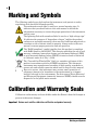
User’s Guide iii General Precautions Before turning on the instrument, carefully read the instructions contained in this manual. Keep this user manual in a safe place for future reference. Follow the installation and operation procedures carefully. Imperatively respect the safety warnings found on the instrument and in this manual. When carrying the Ectane™, it is the user’s responsibility to make sure that the safety precautions used are in accordance with the local department of transportation’s (or equivalent governing body) rules and regulations. The electrical plug shall only be inserted in a power outlet providing a protective earth contact. You must not negate the protective action by using an extension cord (power cable) without a protective conductor (grounding). Grounding one conductor of a two-conductor outlet is not sufficient protection. The instrument must only be connected to a power source corresponding to the type indicated on the rating plate. If the equipment is used in a manner not specified by Eddyfi NDT, Inc., the protection provided on the equipment may be rendered ineffective. Do not install substitute parts or perform any unauthorized modification to the instrument. Service instructions, when applicable, are for trained service personnel only. To avoid dangerous electric shock, do not perform any service unless qualified to do so. For any problem or question regarding this instrument, contact Eddyfi NDT, Inc., or an authorized Eddyfi NDT, Inc. representative. Battery Charger Precautions Note The battery charger is optional. Do not expose the battery charger or its power supply to water or liquids. The charger case is not sealed. Do not open the battery charger or power supply case. They contain no userserviceable parts. Do not cover the fan exhaust or obstruct airflow; this would cause overheating. Use only the included power supply and observe terminal polarity. Place the charger away from external heat sources. General Precautions iv Marking and Symbols The following symbols may be found on the instrument, and pertain to safety regulations that should be followed carefully. The exclamation mark label is used as a general warning sign. It indicates that you should refer to this user manual to obtain the information necessary to ensure the proper protection of the instrument and its users. The lightning flash with arrowhead label is used as a “high voltage sign.” It indicates the presence of “hazardous voltages” (within the product enclosure or accessible externally) that may be of sufficient magnitude to constitute a risk of electric shock to persons. Always refer to the user manual to ensure proper protection and safe practices. The “RoHS compliant” symbol signifies that this product is compliant with RoHS directive 2002/95/EC. This directive prohibits the use of lead, mercury, cadmium, hexavalent chrome, poly-bromated biphenyl (PBB) or poly-bromated diphenyl-ether (PBDE) in certain classes of electrical or electronic units as of July 1, 2006. The “Crossed-Out Wheeled Bin” label is a reminder to dispose of this product in accordance with local WEEE regulations. This electronic instrument was manufactured according to high quality standards to ensure safe and reliable operation when used as stated in this manual. Due to its nature, this instrument may contain small quantities of substances known to be hazardous to the environment or to human health if released in the environment. For this reason, Waste Electrical and Electronic Equipment (commonly known as WEEE) should never be disposed of in the public waste stream. Calibration and Warranty Seals Calibration and warranty seals are hidden under the Ectane’s front left bumper to prevent inadvertent damages. Important Broken seals void the calibration certification and product warranty. Marking and Symbols Table of Contents General Precautions ...................................................................................................................... iii Battery Charger Precautions ......................................................................................................... iii Marking and Symbols ................................................................................................................... iv Calibration and Warranty Seals ..................................................................................................... iv Table of Contents ........................................................................................................................... v Safety Indications ........................................................................................................................ vii Typographical Conventions ........................................................................................................... viii Introducing the Ectane ............................................................ 1 Presentation .................................................................................................................................. What is in the Box .................................................................................................................... Instrument Description ............................................................................................................. Ground Connector .......................................................................................................................... Battery Compartment ..................................................................................................................... 2 2 3 8 9 Preparing the Inspection System .......................................... 11 Setting Up the Instrument ............................................................................................................ Connection Configurations ..................................................................................................... Starting the Instrument ................................................................................................................ Understanding Indicators ............................................................................................................. Power Indicators .................................................................................................................... Battery Indicators ................................................................................................................... Connection Indicators ............................................................................................................ 12 13 15 15 15 16 18 Managing Batteries ............................................................... 19 General ........................................................................................................................................ Charging the Batteries ................................................................................................................. Battery Charger LED Status Indicator ..................................................................................... Removing the Batteries ................................................................................................................ Hot-Swapping Batteries ......................................................................................................... Battery Indicators ......................................................................................................................... 20 20 21 22 22 23 Connector References ........................................................... 25 EXTENDED ET Connector (41 pins) .................................................................................................. RFT/NFT/MFL Connector (19 pins) ................................................................................................ ECT BOBBIN Connector (4 pins) ...................................................................................................... ENCODERS Connector (18 pins) ....................................................................................................... 26 29 31 32 Table of Contents vi IRIS Connector ............................................................................................................................. 34 EDDY CURRENT ARRAY Connectors ................................................................................................... 34 Ethernet Connector ...................................................................................................................... 35 Specifications ........................................................................ 37 General ....................................................................................................................................... System .................................................................................................................................. Power Requirements ............................................................................................................. Environmental Conditions ...................................................................................................... Housing ................................................................................................................................. Ethernet Cable ....................................................................................................................... By Inspection Technique .............................................................................................................. Eddy Current (ECT) ................................................................................................................ Eddy Current Array (ECA) ....................................................................................................... Remote Field Testing (RFT / NFT) ............................................................................................ Magnetic Flux Leakage (MFL) ................................................................................................ Internal Rotary Inspection System (IRIS) ................................................................................. 38 38 38 39 39 39 40 40 41 41 42 42 Maintenance & Troubleshooting ............................................. 45 Preventive Maintenance .............................................................................................................. Cleaning the Instrument ........................................................................................................ Calibrating Batteries .................................................................................................................... Troubleshooting ........................................................................................................................... Firmware Corruption .............................................................................................................. 46 46 47 47 47 Accessories ............................................................................ 49 Protective Caps ........................................................................................................................... Adapters and Connectors ............................................................................................................ Battery Charger and Batteries ...................................................................................................... Remote Control ........................................................................................................................... 50 50 50 50 Warranty, Trademarks, Copyrights ......................................... 51 Limited Warranty ......................................................................................................................... 52 Trademarks ................................................................................................................................. 52 Copyrights ................................................................................................................................... 53 Table of Contents vii Safety Indications The purpose of the various safety indications is to ensure operator safety and instrument integrity. WARNING! The WARNING sign denotes a hazard. It calls attention to a procedure, practice, or the like, which, if not correctly performed or adhered to, could result in personal injury. Do not proceed beyond a WARNING sign until the indicated conditions are fully understood and met. CAUTION The CAUTION sign denotes a hazard. It calls attention to a procedure, practice, or the like, which, if not correctly performed or adhered to, could result in material damage or loss of data. Do not proceed beyond a CAUTION sign until the indicated conditions are fully understood and met. Important The Important sign calls attention to a note that provides important information, or information essential to the completion of a task. Note The Note sign calls attention to an operating procedure, practice, or the like, that requires special attention. A Note also denotes related, parenthetical information that is useful, but not imperative. Safety Indications viii Typographical Conventions The various typographical conventions explained below were defined to standardize and simplify the look and feel of this documentation. Italic An italic typeface is used to indicate emphasis on a specific word or phrase (i.e., This options should never be checked.) Bold A bold typeface is used to indicate the name of a menu item or a named user interface element (i.e., the File menu, the Options button, etc.) Generally, items in bold are capitalized to reflect the capitalization used on screen. SMALL CAPITALS Small capitals are generally used when reference is made to inscriptions found “as is” on an instrument (buttons, connectors, indicator lights, etc.) Typographical Conventions Introducing the Ectane 2 Presentation Eddyfi’s innovative Ectane™ instrument completely redefines the potential of electromagnetic technologies (ET) for surface and tube inspection. This highperformance ET data acquisition system offers the following top-of-the line key features: Light, rugged, portable, and sealed SmartMUX™: integrated, universal, and programmable array multiplexer for up to 256 elements Multi-technology for tube inspections: ECT, RFT, NFT, MFL, ECA, and IRIS1 ultrasound technology Battery power and backup, for flexibility and 100% uptime Plug & Play connectivity – no more BootP! Standard connectors The Ectane is controlled by a remote PC running Microsoft Windows XP or Windows 7 and Eddyfi’s Magnifi® software. This PC will be referred to as the workstation in this manual. For more information about Magnifi, please refer to its user manual. What is in the Box All Ectane instruments come with the following standard accessories: 1. Two high-capacity batteries One power adapter (100 V – 240 V) Power cords (one for North America and one for Europe) Ballistic nylon shoulder strap High-quality shielded Ethernet cable One 41-to-4-pin adapter (with Ectane E and Ectane E64 models only) User manual Transportation case Patent pending Chapter 1: Introducing the Ectane Presentation 3 Instrument Description At this time, the Ectane is available in 11 different configurations. Numbers after the Ectane name indicate the maximum number of channels available with this instrument. The “RNM” option indicates RFT, NFT, and MFL capabilities. The “I” option indicates IRIS capabilities Available configurations are: Ectane E Ectane E64 Ectane E128 Ectane E256 Ectane EI Ectane ERNM Ectane ERNMI Ectane E64RNM Ectane E64RNMI Ectane E128RNM Ectane E128RNMI Front Plate Descriptions Ectane instruments come in one of eight different front plates: Ectane E (without SmartMUX) Ectane E64 and Ectane E128 Ectane E256 Ectane I Ectane ERNM (without SmartMUX) Ectane ERNMI (without SmartMUX) Ectane E64RNM and Ectane E128RNM Ectane E64RNMI and Ectane E128RNMI Presentation 4 Figure 1 Ectane E Figure 2 Ectane I ( W Chapter 1: Introducing the Ectane , Presentation 5 Figure 3 Ectane E64 and Ectane E128 Figure 4 Ectane E256 Presentation 6 Figure 5 Ectane ERNM RFT/NFT/MFL Figure 6 Ectane ERNMI Chapter 1: Introducing the Ectane Presentation 7 Figure 7 Ectane E64RNM and Ectane E128RNM RFT/NFT/MFL Figure 8 Ectane E64RNMI and Ectane E128RNMI ( W Presentation ( 510, 8 Ground Connector Behind the instrument, you will find the ground connector used to ground the Ectane when the situation requires it. Figure 9 Ground connector The ground connector is a simple screw that you remove to insert the ground wire, putting the screw back in to secure the connection. Chapter 1: Introducing the Ectane Ground Connector 9 Battery Compartment The Ectane can be powered either from an external AC/DC power supply or via two high-power batteries. These batteries are accessible from a side access panel, as shown below. Figure 10 Battery compartment door Backup firmware button Important The backup firmware button is used in cases where the Ectane’s original startup firmware becomes corrupted. The troubleshooting procedure to perform in case of firmware corruption is given in the Magnifi documentation. Battery Compartment Preparing the Inspection System 12 Setting Up the Instrument To properly set up the Ectane™: 1. Remove the instrument from the transportation case. 2. Position the instrument on a level and stable surface. You can position it either horizontally or vertically. WARNING! Never use the instrument if it is positioned upside down (batteries on top). This position prevents batteries from dissipating heat properly and could lead to the Ectane going into “power safe mode.” For more information on the “power safe mode”, see “Environmental Conditions” on page 39. Important Regardless of how you position the instrument, you must always have at least 10 centimeters (4 inches) of clearance on all sides of the instrument. You must also always position the instrument away from heat sources. This ensures proper heat dissipation while the instrument is in use. CAUTION When in use, and depending on the loaded setup, the instrument can generate a non negligible amount of heat. The amount of heat generated should not cause any kind of harm, but could prove uncomfortable to the touch. When moving the instrument, you should use the carrying handle. Chapter 2: Preparing the Inspection System Setting Up the Instrument 13 Connection Configurations The Ectane allows various test configurations. The following figures show you some of these configurations. Figure 1 Typical configuration 1: Ectane with SmartMUX™ ECA Probe Figure 2 Typical configuration 2: Ectane with SmartMUX, external drive unit, scanner, and probe ECA Probe External Drive Unit Scanner Unit Setting Up the Instrument 14 Figure 3 Typical configuration 3: Ectane with external multiplexer, external drive unit, scanner, and probe ECA Probe External multiplexer External Drive Unit Scanner Unit Figure 4 Typical configuration 4: Ectane with probe-integrated multiplexer ECA Probe Chapter 2: Preparing the Inspection System Setting Up the Instrument 15 Starting the Instrument Once you have properly connected all the instruments in your inspection setup, you can start the Ectane. To start the Ectane: 1. Connect the power adapter to the power cord. 2. Connect the power adapter to the power socket on the front of the Ectane. 3. Connect the power cord to the wall outlet. 4. Press the ON/OFF button until it clicks. An orange LED lights up on the ON/OFF button, and all indicators on the front of the instrument light up as well. Note If you want to work from the batteries, simply press the ON/OFF button. Understanding Indicators There are various indicators on the front of the Ectane. The following pages explain the various behaviors of these indicators. Power Indicators Two indicators are assigned to the instrument power status: Power switch indicator Circular LED integrated in the ON/OFF switch. Should light orange when the Ectane is powered on. External power indicator Should light green when the external AC adapter is connected and powered. Starting the Instrument 16 Figure 5 Power Indicators Power switch indicator External power indicator Battery Indicators Each battery has its own charge level indicator, and charging status indicator. Figure 6 Battery B indicators Charge level indicators Charging status indicators Chapter 2: Preparing the Inspection System Understanding Indicators 17 Figure 7 Battery corresponding to battery indicators Battery A Battery B Charge level indicators light up and/or flash depending on each battery’s charge level, as explained below: LED 1 (from bottom) is flashing Charge is less than 10% LED 1 (from bottom) is solid Charge is over 10% LED 2 is solid Charge is over 25% LED 3 is solid Charge is over 50% LED 4 is solid Charge is over 75% Charging status indicators can have one of three states: Note Off When two conditions are present: no external power is present instrument is turned off Green Battery is fully charged Yellow Battery charging Indicators are set off for up to 1 minute when the instrument in powered on. Understanding Indicators 18 Connection Indicators Just above the Ethernet port, two indicators give information on the state of the communication between the Ectane and your workstation. Figure 8 Connection Indicators Connection speed indicator Connection indicator The connection speed indicator can be in either of two states: On (green) Communication is established at 100 Mbps Off Communication is established at 10 Mbps The connection indicator can also be in either of two states: Flashing (green) Communication is being established between the Ectane and the workstation Solid (green) Communication is established between the Ectane and the workstation Chapter 2: Preparing the Inspection System Understanding Indicators Managing Batteries 20 General The Ectane™ uses lithium-ion–type rechargeable batteries. This type of battery does not suffer from the “memory effect” affecting batteries of previous generations. WARNING! Whenever carrying the Ectane in its transportation case, YOU MUST remove the batteries from the instrument and make sure that they can not come in contact during transport, as this could result in a significant fire or explosion hazard. When carrying the Ectane, it is the user’s responsibility to make sure that the safety precautions used are in accordance with the local department of transportation’s (or equivalent governing body) rules and regulations. The transportation case provided with the Ectane comes with two slots fitted to receive batteries once removed from the instrument. Use them. Charging the Batteries Usually, batteries charge automatically in the Ectane whenever the instrument is plugged in a wall outlet and turned on. Note Batteries will not charge if their internal temperature exceeds 45 °C (113 °F). Also, batteries will not power the Ectane if the instrument’s internal temperature exceeds 55 °C (131 °F). However, Eddyfi provides an optional external charger that also conditions and calibrates your batteries, which is important to maximize their useful lifespan and ensure accurate readings for the battery charger indicator in Magnifi®. Eddyfi recommends calibrating batteries at least every six months (for more information on calibrating batteries, see “Calibrating Batteries” on page 47). Chapter 3: Managing Batteries General 21 Figure 1 Battery charger Battery bays Calibration buttons Status window To charge the batteries using the optional external charger: 1. Place the charger on a flat and level surface, away from sources of heat and moisture. 2. Plug the DC connector from the power supply into the back of the charger. 3. Connect the power supply to the mains AC supply using the supplied cable. All LEDs will flash momentarily to let you know that power is present. 4. Place the battery into either of the battery bays, ensuring that the 5-way connector is fully seated. The LEDs in the status window will provide status information, and the charger will automatically begin charging. Battery Charger LED Status Indicator When batteries are inserted in the charger, status LEDs light up in the status window: Green (flashing) Battery is charging Green (solid) Battery is fully charged Blue (flashing) Battery in calibration mode Blue (solid) Battery fuel gauge calibrated Red (flashing) Battery gauge in need of calibration Red (solid) Error Charging the Batteries 22 Removing the Batteries Normally, you can leave the batteries in the Ectane as long as you want. However, there will be times when you will have to remove them from Ectane (i.e., for calibration purposes, or before putting the instrument on a plane). To do so: 1. Turn each screw of the battery compartment door a quarter turn counterclockwise. The battery compartment door pops out. Figure 2 Opening the battery compartment door Battery tab Screws Battery latch Note The screws are designed to stay with the compartment door. 2. Press down the latch holding the battery in place. 3. Pull on the battery tab. The battery slides out. Note The battery compartment is designed to hold the batteries firmly. You might need to use a certain amount of force to pull out the batteries. Hot-Swapping Batteries Batteries in the Ectane can be removed, one at a time, while the instrument is powered up. Normally, the Ectane can run off only one battery. Should the power left in the remaining battery be insufficient to keep the Ectane up and running, the instrument will shut down without damaging the electronics. However, all work in progress within Magnifi (acquisition, etc.) will be lost. Chapter 3: Managing Batteries Removing the Batteries 23 Battery Indicators Each battery has its own charge level indicator, and charging status indicator. For more information on which charge level indicator relates to which battery, see “Battery Indicators” on page 16. Figure 3 Battery B indicators Charge level indicators Charging status indicators Charge level indicators light up and/or flash depending on each battery’s charge level, as explained below: LED 1 (from bottom) is flashing Charge is less than 10% LED 1 (from bottom) is solid Charge is over 10% LED 2 is solid Charge is over 25% LED 3 is solid Charge is over 50% LED 4 is solid Charge is over 75% Charging status indicators can have one of three states: Note Off When two conditions are present: no external power is present instrument is turned off Green Battery is fully charged Yellow Battery charging Indicators are set off for up to 1 minute when the instrument in powered on. Battery Indicators Connector References 26 EXTENDED ET Connector (41 pins) The EXTENDED ET connector is used to connect eddy current probes. The signals contained in the EXTENDED ET connector are the eddy current generator outputs, the eddy current channel amplifier inputs, the multiplexing outputs, and a DC power supply. Figure 1 Description 41-pin, female, shell 20 connector Manufacturer, number Amphenol 58-570127-41S Eddyfi NDT, Inc., MACN4012 Suggested cable connector ITT Cannon, KPT06B20-41P or Amphenol PT06J-20-41P Eddyfi NDT, Inc., MACN0005 EXTENDED ET connector A B C X Y D V j U i Z E m a F k s S n r b G g p R q ç H f P d e J N K Table 1 T h L M EDDY CURRENT connector pinout Pin I/O Signal Description A Output ECT1 generator ECT1 eddy current generator output B, C, D, E, Outputs ECT1 Generator / 100 Ω F, G, H ECT1 eddy current generator outputs through 100 Ω J – Multiplexer mode selection K Input Identification Probe identification L – GND Power supply ground to the instrument and casing M Output ECT2 generator ECT2 eddy current generator output Chapter 4: Connector References EXTENDED ET Connector (41 pins) 27 Table 1 EDDY CURRENT connector pinout (continued) Pin I/O N, P Outputs ECT2 Generator / 100 Ω ECT2 eddy current generator outputs through 100 Ω R, S Outputs ECT2 Generator / 100 Ω ECT2 eddy current generator outputs through 100 Ω (if external MUX is not connected) R Output MUX 4 Multiplexing signal output (bit 4) S Output MUX 5 Multiplexing signal output (bit 5) T Output MUX 0 CLK – Multiplexing signal output (bit 0) (if pin J is not grounded) Clock – signal (if pin J is grounded) U Output MUX 1 CLK + Multiplexing signal output (bit 1) (if pin J is not grounded) Clock + signal (if pin J is grounded) V Output MUX 2 +12.5 V supply Multiplexing signal output (bit 2) (if pin J is not grounded) +12.5 V supply voltage (if pin J is grounded) W Output MUX 3 –12.5 V supply Multiplexing signal output (bit 3) (if pin J is not grounded) –12.5 V supply voltage (if pin J is grounded) X – GND Power supply ground to the instrument and casing Y Output –15 V supply –15 V supply voltage (1.0 A max.) Z Input In1 + input Positive input of input amplifier 1 a Input In1 – input Negative input of input amplifier 1 b Input In2 + input Positive input of input amplifier 2 c Input In2 – input Negative input of input amplifier 2 d Input In3 + input Positive input of input amplifier 3 e Input In3 – input Negative input of input amplifier 3 f Input In4 + input Positive input of input amplifier 4 g Input In4 – input Negative input of input amplifier 4 h – GND Power supply ground to the instrument and casing EXTENDED ET Connector (41 pins) Signal Description 28 Table 1 EDDY CURRENT connector pinout (continued) Pin I/O Signal Description i Input In5 + input Positive input of input amplifier 5 j Input In5 – input Negative input of input amplifier 5 k Input In6 + input Positive input of input amplifier 6 m Input In6 – input Negative input of input amplifier 6 n Input In7 + input Positive input of input amplifier 7 p Input In7 – input Negative input of input amplifier 7 q Input In8 + input Positive input of input amplifier 8 r Input In8 – input Negative input of input amplifier 8 s – GND Power supply ground to the instrument and casing t Output +15 V supply +15 V supply voltage (1.0 A max.) Chapter 4: Connector References EXTENDED ET Connector (41 pins) 29 RFT/NFT/MFL Connector (19 pins) The RFT/NFT/MFL connector is used to connect the remote field (RFT) and magnetic flux leakage probes. The signals contained in the RFT/NFT/MFL connector are the RFT generator outputs, the RFT channel amplifier inputs, and a DC power supply. Figure 2 Description 19-pin, female, shell 14 connector Manufacturer, number Amphenol, 58-570124-19S or Souriau 851-02E1419S50A7 Eddyfi NDT, Inc., MACN4015 Suggested cable connector ITT Cannon, KPT06A14-19P027 or Amphenol PT06J-14-19P Eddyfi NDT, Inc., MACN4021 RFT/NFT/MFL Connector A B P C R D L U V S E Table 2 M N T F G K J H RFT/NFT/MFL connector pinout Pin I/O Signal Description A – GND Ground B Input RFT_IN 4- / MFL4 Negative input C Input RFT_IN 3+ Positive input D Input RFT_IN 3- / MFL3 Negative input +15 V supply +15 V supply voltage, 1.0 A max. E F Output Drive2_OUT Coil driver #2 output G – GND Ground RFT/NFT/MFL Connector (19 pins) 30 Table 2 RFT/NFT/MFL connector pinout (continued) Pin I/O Signal Description H Output Drive1_OUT Coil driver #1 output -15 V supply -15 V supply voltage, 1.0 A max. J K Input RFT_IN 2+ Positive input L Input RFT_IN 2- / MFL2 Negative input M Input RFT_IN 1+ Positive input N Input RFT_IN 1- / MFL1 Negative input P Input RFT_IN 4+ Positive input R – GND Ground S Input Identification Probe identification T – NC No connection U – GND Ground V – GND Ground Chapter 4: Connector References RFT/NFT/MFL Connector (19 pins) 31 ECT BOBBIN Connector (4 pins) The ECT BOBBIN connector allows you to connect standard 4-pin inspection probes. Figure 3 Table 3 Description 4-pin, female, shell 14 connector Manufacturer, number Amphenol ACS02A-14S-2S(472) Eddyfi NDT, Inc., MACN4020 Suggested cable connector Amphenol 97-3106A-14S-2P Eddyfi NDT, Inc., MACN0059 ECT BOBBIN Connector A D B C ECT BOBBIN connector pinout Pin Signal A Bobbin Abs/Diff B Bobbin Diff C GND D GND ECT BOBBIN Connector (4 pins) 32 ENCODERS Connector (18 pins) The ENCODERS connector allows the instrument to send and receive various signals such as acquisition start and stop commands, encoder and rotation synchronization signals, relay outputs, etc. Figure 4 Description 18-pin, female, shell 14 connector Manufacturer, number Amphenol 58-570124-18S Eddyfi NDT, Inc., MACN4014 Suggested cable connector ITT Cannon, KPT06B14-18P or Amphenol PT06J-14-18P Eddyfi NDT, Inc., MACN0011 ENCODERS Connector B A P C E L U R D Table 4 M N K J T H S F G ENCODERS connector pinout Pin I/O Signal Description A TTL Input B1 Phase B axis 1 B Output CLK_ACQ_OUT Acquisition clock output (open drain with 10 kΩ pull-up) C TTL Input A2 Phase A axis 2 D – GND Encoders ground E TTL Input Input 1 User-defined input for software and hardware function activation. F TTL Input Input 3 User-defined input for software and hardware function activation. G TTL Input Input 2 User-defined input for software and hardware function activation. Chapter 4: Connector References ENCODERS Connector (18 pins) 33 Table 4 ENCODERS connector pinout (continued) Pin I/O Signal Description H Output Alarm Used to indicate that the probe is in the air (for tube inspections) (open drain with 10 kΩ pull-up) J Relay contact Relay 2 Relay used for automatic acquisition sequence control K Relay contact Relay 3 Relay used for automatic acquisition sequence control L Relay contact Relay 1 Relay used for automatic acquisition sequence control M TTL Input CLKACQ Receives signal to trigger acquisition with probe position along the scanning axis. NC No connection N P TTL Input B2 Phase B axis 2 R TTL Input A3 / Input 5 Phase A axis 3, or user-defined input for automatic acquisition sequence S Supply Output +5 V 5 V supply output, 250 mA max T TTL Input B3 /Input 4 Phase B axis 3, or user-defined input for automatic acquisition sequence U TTL Input A1 Phase A axis 1 ENCODERS Connector (18 pins) 34 IRIS Connector The IRIS connector allows the instrument to control IRIS probes. Description BNC Adapter, bulkhead, 50 Ω Manufacturer, number Amphenol 31-220N-RFX Eddyfi NDT, Inc., MACN4022 Suggested cable connector POMONA, 2249-C-120 Eddyfi NDT, Inc., MAME0021 Figure 5 IRIS Connector Table 5 IRIS connector pinout Pin Signal Description Center Pulser output Receiver input Ultrasound pulser outputs and ultrasound receiver input Shell Power supply common to the instrument and casing Ground EDDY CURRENT ARRAY Connectors On Ectane™ units with the SmartMUX™ option, 160-pin connectors are available on the front of the instrument, under EDDY CURRENT ARRAY. These connectors are specific and designed by Eddyfi. For more information on the Eddyfi 160-pin connectors, please contact Eddyfi directly at [email protected]. Chapter 4: Connector References IRIS Connector 35 Ethernet Connector The Ethernet connector is used to connect the Ectane to the workstation via an Ethernet or Fast Ethernet link. Eddyfi provides a high-quality, military-grade circular Ethernet connector and cable. International Ethernet standards are used. Description RJ-45, female connector Manufacturer, number PEI Genesis, Amphenol RJF22B00SCC Eddyfi NDT, Inc., MACN4016 Figure 6 Ethernet connector Table 6 Ethernet connector pinout Pin I/O Signal Description 1 Output TX+ Data transmission 2 Output TX– Data transmission 3 Input RX+ Data reception 4 – NC No connection 5 – NC No connection 6 Input RX– Data reception 7 – NC No connection 8 – NC No connection Important The Ectane must be linked to the workstation with at least a category 5e, shielded, Ethernet cable. Ethernet Connector Specifications 38 General This section presents the Ectane™ system general specifications. System Warm-up timea 15 minutes Workstation link Ethernet 100BaseT Transfer rate on Ethernet cable 100 Mbps a. The warm-up time corresponds to the time required by the unit to reach its optimal accuracy after power-up. Eddyfi recommends to wait until the end of the warm-up tim before balancing probes and performing acquisitions. Power Requirements Power configuration 100 W external AC/DC power supply of 15 VDC, or battery (removable) Voltage 100 – 240 VAC, ±10 % Frequency 50 / 60 Hz Maximum input current 1.5 A Battery type Lithium-ion, rechargeable, DOTcompliant Battery lifea 8 hours a. Typical (with two batteries in the instrument) Chapter 5: Specifications General 39 Environmental Conditions Operating temperaturea 0 °C to 45 °C (32 °F to 113 °F) Storage temperature –20 °C to 60 °C (–4 °F to 140 °F) Relative humidity 95%, non-condensing Pollution degree rating 2 Protection Designed of IP64 Compliance ASME, EN61010-1, EMC, CE, WEEE, RoHS a. The Ectane warn you through Magnifi® when its operating temperature reaches 65 °C. It enters “power safe mode” to better protect itself when the operating temperature reaches 70 °C. In “power safe mode”, some internal circuitry shuts down, acquisitions are stopped, and the instrument becomes inactive for work purposes until the condition that initiated the “power safe mode” is corrected. Housing Dimensions (W × H × D)a 279.6 mm × 254.0 mm × 158.8 mm. (11.00 in. × 10.00 in. × 6.25 in) Net weightb 6.8 kg (15 lb) a. b. The outline dimensions include the handle. Ectane E64 or E128 with batteries. Ethernet Cable General Type At least category 5e, shielded Maximum length 100 m (328 ft) 40 By Inspection Technique This section presents the Ectane’s operating specifications by inspection technique. Eddy Current (ECT) Probe inputs 8 Number of frequencies 8 Frequency range 5 Hz – 4 MHz Generator / Coil driver 2 Generator output / Coil drive Up to 20 V, peak-to-peak Injection modes Multiplexed, simultaneous, continuous Receiver gain 35 dB range, 23 – 58 dB Data resolution 16 bits Acquisition / sampling rate Up to 40,000 / sec. Compatible with external multiplexer Through 41-pin extended ET connector Number of channels (via external multiplexer) up to 64 per ECT frequency (max. 5 frequencies) Chapter 5: Specifications By Inspection Technique 41 Eddy Current Array (ECA) Number of channels Ectane E64 Up to 64 channels for each ECT frequency (max. 5 frequencies) Ectane E128 Up to 128 channels for each ECT frequency (max. 5 frequencies) Ectane E256 Up to 256 channels for each ECT frequency (max. 2 frequencies) OR Up to 128 channels for each ECT frequency (max. 5 frequencies) Multiplexer SmartMUX™: integrated, universal, and programmable Connector typea Single or double 160-pin connector a. The Ectane uses an ID device found in Eddyfi probes. This ID device contains information that helps in setting up acquisitions and confirm compatibility between setup and probe. Remote Field Testing (RFT / NFT) Probe inputs 4 Number of frequencies 5 Frequency range 5 Hz – 100 kHz Generator / Coil driver 2 Generator output / Coil drive 20 V, peak-to-peak Receiver gain 50-dB range, 36 – 86 dB Acquisition / sampling rate Up to 20,000 / sec. Connector type 19-pin RFT/NFT connector By Inspection Technique 42 Magnetic Flux Leakage (MFL) Probe inputs 4 Receiver gain 35-dB range, 12 – 47 dB Connector type 19-pin RFT/NFT connector Internal Rotary Inspection System (IRIS) Number of UT channels 1, pulse-echo Transducer frequency 5, 10, 15, or 20 MHz Pulsing rate Up to 28 kHz Pulser voltage 75 – 200 V (25-V steps) Pulse width Automatically adjusted for 5, 10, 15, or 20 MHz transducer Receiver gain 8 – 72 dB (in 1-dB steps) Receiver DAC Up to 15 dB/µs RF Filters 4 user-selectable filters for 5-, 10-, 15-, and 20-MHz transducers Digitizer 12-bit, 100 MHz Gates 3; needle, front wall, back wall Chapter 5: Specifications By Inspection Technique Maintenance & Troubleshooting 46 Preventive Maintenance Due to its design, the Ectane™ requires only minimal maintenance. Since it has no moving parts, it does not require any preventive maintenance from the user. Only a regular inspection of the instrument is recommended, to ensure that it is properly grounded. Also, Eddyfi strongly recommends an annual calibration and a factory-performed preventive maintenance by an officially qualified Eddyfi technician. Cleaning the Instrument The Ectane external surfaces, that is, the casing and the front panel, can be cleaned when needed. This section provides the procedure for the appropriate cleaning of the instrument. To clean the instrument 1. Make sure the instrument is turned off and the power cord is disconnected. 2. To bring the instrument back to its original finish, clean the casing and the front panel with a soft cloth. WARNING! Do not clean the instrument with a water jet, spray can, or spray bottle. Connector contacts could stay wet and produce a short circuit when plugging cables. To get rid of persistent stains, use a damp cloth with a soft soapy solution. Do not use abrasive products or powerful solvents that might damage the finish. Wait until the instrument is completely dry before plugging in the power cord and cables. Chapter 6: Maintenance & Troubleshooting Preventive Maintenance 47 Calibrating Batteries To ensure that your batteries will perform to their full capacity for the longest possible time, it is important to calibrate them at regular intervals. Calibration consists of a standard battery charge followed by a deep discharge and, finally, a complete charge. This procedure usually takes between 10 and 13 hours, whereas a standard charge takes about 3.5 hours. This calibration can be performed simply by placing the batteries in the external charger (optional) and pressing the Recalibrate button (See “Managing Batteries” on page 19.) Eddyfi recommends calibrating your batteries at least once every six months. CAUTION During calibration, the charger may become warm. Troubleshooting You cannot troubleshoot the Ectane without first connecting it to a workstation running Magnifi®. Thus, troubleshooting tips are given in the Magnifi documentation. Firmware Corruption In case of firmware corruption, you will need to start up the instrument from a backup firmware. This procedure is explained in the Magnifi documentation, but to locate the backup firmware button, see “Battery Compartment” on page 9. Calibrating Batteries Accessories 50 Protective Caps If you need to go in challenging inspection environments, where dust or nuclear contamination is present, you will need protective caps to cover the Ectane™ connectors. All connectors have a specific protective cap. Contact your Eddyfi representative for more information on pricing and availability. Adapters and Connectors The Ectane connectors were chosen to match the most common connectors in use today. However, you might have specific needs outside of the connectors provided on the Ectane. Eddyfi offers a comprehensive list of adapters and specialty connectors to suit your needs. Contact your Eddyfi representative for more information on pricing and availability. Battery Charger and Batteries The Ectane is delivered with batteries. However, depending on your work environment and your workload, you might need to have more than the provided batteries, and you might need the optional battery charger. Contact your Eddyfi representative for more information on pricing and availability. Remote Control The Ectane can be operated remotely via the optional remote control. Contact your Eddyfi representative for more information on pricing and availability. Appendix A: Accessories Protective Caps Warranty, Trademarks, Copyrights 52 Limited Warranty Eddyfi NDT, Inc., warrants the hardware to be free of any defects in materials or workmanship for a period of twelve (12) months from the date of delivery, under normal use and service. These warranties are limited to the original purchase of the product and are not transferable. Eddyfi NDT, Inc. will repair or replace any product component or documentation, at its option and at no additional charge, if found defective within the warranty period. The purchaser is responsible for returning the product to Eddyfi NDT, Inc. Eddyfi NDT, Inc., will not be held responsible in any way whatsoever for damage resulting from improper installation, accident, misuse, or from service or modification of the product by anyone other than Eddyfi NDT, Inc., or an authorized Eddyfi NDT, Inc. service center. Eddyfi NDT, Inc. will not be held responsible in any way whatsoever for direct, indirect, special, incidental, or consequential damages resulting from possession, use, improper installation, accident, service, modification, or malfunction of the product (including, without limitation, damages for loss of business profits, business interruption, loss of business information, or other pecuniary loss). Eddyfi’s total shall in no event exceed the purchase price of the applicable item(s). This warranty is in lieu of all other warranties, whether oral, written, expressed, or implied, including any warranty of merchantability or fitness for a particular purpose, and no other representation or claims of any nature shall be binding on or obligate Eddyfi NDT, Inc. This agreement is governed by the laws of the province of Québec, Canada. Each of the parties hereto irrevocably attorns to the jurisdiction of the courts of the province of Québec and further agrees to commence any litigation which may arise hereunder in the courts located in the judicial district of Québec. Trademarks Eddyfi™, Ectane™ and Magnifi®, along with the associated logos, are registered trademarks of Eddyfi NDT, Inc. You must obtain written consent from Eddyfi before using any of these marks. Eddyfi reserves the right to change, without notice, product offerings or specifications. Appendix B: Warranty, Trademarks, Copyrights Limited Warranty 53 Copyrights This manual and the product and programs it describes are protected by the Copyright Act of Canada, by laws of other countries, and by international treaties, and therefore may not be reproduced, in whole or in part, whether for sale or not, without prior written consent from Eddyfi NDT, Inc. Under copyright law, copying includes translation in another language or format. © Eddyfi NDT, Inc., 2013 This document was prepared with particular attention to usage to ensure accuracy of the information contained therein. It corresponds to the version of the product manufactured prior to the date appearing on the title page. There may, however, be some differences between the manual and the product, if the product has been modified thereafter. The information contained in this document is subject to change without notice. Manual version G Part number: SXSC2001G First edition, June 2011 Copyrights T + 1 418-780-1565 F + 1 418-780-2354 [email protected] www.eddyfi.com © Eddyfi NDT, Inc. Eddyfi, Ectane, Magnifi, and their associated logos are trademarks or registered trademarks of Eddyfi NDT, Inc. Eddyfi reserves itself the right to change product offerings and specifications without notice. 2013-10-16 SXSC2001G