1
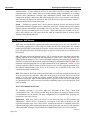
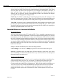
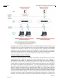
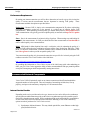
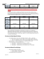
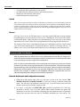
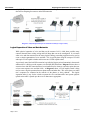
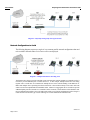
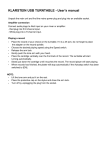
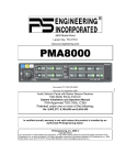
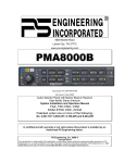
Voice Carrier Preparing Your Network For Voice Carrier VoIP Voice Carrier Preparing Your Network For Voice Carrier VoIP Version 1.0 Page 1 of 15 Voice Carrier Preparing Your Network For Voice Carrier VoIP Version 1.0 Last Edited: 3/11/2014 Summary This document is intended to help Voice Carrier Partners and Customers prepare their networks for implementation of Voice Carrier Services. The concepts discussed in this document can be applied to installation of any Voice Carrier product and are intended to educate the reader on the various, general network components and also provide information on Voice Carrier specific requirements and concepts. Upon reading this document the customer or Partner should have a better understanding of how to evaluate and prepare a network prior to attempting to deploy Voice Carrier services. In addition, the terms and concepts introduced in this document are intended to help Voice Carrier partners determine where they may need to spend additional time researching and educating themselves on the concepts that are instrumental in becoming a successful user and evangelist for Voice Carrier SIP based VoIP services. Description of Network Components and Terms By adhering to the recommendations provided in this document, Voice Carrier Partners and Customers will be able to prepare their network for deploying Voice Carrier Services. While implementation models may vary slightly based on product, general recommendations will be provided that will help ensure successful implementation and operation of Voice Carrier services. Internet Service Provider (ISP) - All Voice Carrier services are IP based and as a result rely heavily, if not entirely, on the customer’s connection to the internet. This connection is provided by the customer’s ISP and can range from dedicated fiber or metro Ethernet to cable internet or DSL. The choice of ISP is one of the most important choices that can be made when making the decision to move to VoIP since the speed and stability of the ISP will likely have the greatest impact on the quality of service. IP Addresses - IP addresses are used to uniquely identify devices on a network and are classified as either ‘public’ or ‘private’ IP addresses as defined in RFC 1918 (http://en.wikipedia.org/wiki/Private_network). The customer’s ISP will typically distribute one or more public IP address to the customer and the public IP will be assigned to the WAN interface of the customer’s router or modem/router. Modem - a modem is provided with services such as cable internet and DSL and is the demark between the ISP and the customer’s internal network. An Ethernet handoff is typically provided from the modem to the customer. In some cases the modem provided by the ISP actually contains router and/or firewall functionality as described below. When a separate router/firewall is to be used by the customer, the modem must be set to “bridge mode” to avoid issues with double NAT (Network Address Translation) that can negatively impact voice traffic. Version 1.0 Page 2 of 15 Voice Carrier Preparing Your Network For Voice Carrier VoIP Router - In the purest sense a router is a device that routes packets between various IP subnets/networks. A router makes the decision to route traffic based on its routing table which is populated either via static routes which are provided manually during configuration or via routing protocols which automatically exchange route information between routers based on network configuration and status. Most routers that will be deployed by Voice Carrier customers will likely use static route and will simply route between the ISP on the WAN side of the router and the customer’s internal network on the LAN side of the router. Switch - Switches are generally layer 2 devices that are deployed in Local Area Network (LAN) environments and used to aggregate device connections on the LAN. Switches can be used to segment Ethernet networks and connect a large number of devices on a Layer 2 network to a layer 3 network which is typically represented by the use of a router. While some higher end switches can act as a router, most switches you will work with do not make IP routing decisions or perform firewall functions such as filtering and NAT. Voice Carrier VoIP Basics While there are many different signaling and media protocols that can be used for VoIP traffic, all conversations regarding Voice Carrier VoIP will assume that SIP/UDP is being used as the signaling method and RTP/UDP is being used for all media. When working with VoIP service there are two types of IP traffic that need to be handled properly in order for call setup and voice communication to be successful. SIP: SIP stands for Session Initiation Protocol. SIP is used for call setup, tear down, and all other signaling required for the management and manipulation of VoIP service. While SIP primarily uses UDP port 5060 for transport, Voice Carrier recommends configuring your router/firewall so that ports 5060-5070 are prioritized outbound to the internet and with the recommended settings described in this document so that the appropriate two way SIP communication can be maintained.. NOTE: It is not typically required to explicitly permit any traffic inbound as this is usually implicitly permitted due to the outbound communication of the device on the customer site as described in the “How VoIP communication works” section below. RTP: RTP stands for Real-Time-Protocol and is the actual voice traffic that is transmitted once the call is set up between the two endpoints. Many calls can be going on at the same time from one site to another so a wide range of ports are typically available for RTP traffic so that each call can be designated a unique port. While a smaller subset of ports is typically needed, UDP ports 10,000-20,000 are earmarked for RTP traffic and can be used when establishing rules to allow and prioritize VoIP traffic as needed. How VoIP Communication Works: The following represents a very basic, high level description of how Voice Carrier VoIP communications work. This is being provided solely for the purpose of helping to illustrate why the recommendations for both network and device configuration are so important when preparing your network for Voice Carrier services. Registration: With Voice Carrier, all services are SIP based and relay on SIP registration and authentication. When a device is connected to your network it will make an attempt to send SIP registration messages to the Voice Carrier cloud. Assuming the network is configured properly the registration messages will be exchanged between the cloud system and your device(s) and registration will be established. Messages will periodically be exchanged between the Voice Carrier cloud and Version 1.0 Page 3 of 15 Voice Carrier Preparing Your Network For Voice Carrier VoIP your SIP devices in order to maintain this registration status. It is these periodic messages that keep connections open through your router/firewall and allows for consistent two way communication. If for any reason your router/firewall closes this connection between your phone and the Voice Carrier cloud, the phone will either become unregistered or will be flagged as unreachable by the PBX. In either case Voice Carrier services will cease to function properly. It is for this reason that it is imperative that you follow the network recommendations provided in this document and configure your equipment with the appropriate settings provided. Call Set Up: In addition to establishing and maintaining Registration status, SIP messages are also used to set up and tear down VoIP calls. When call set up is performed, both ends acknowledge set up of the call and establish the appropriate ports for sending and receiving of the call media (RTP) traffic. Voice Calls: Once the call set up is complete the PBX and the device making or receiving the call will pass the actual call media back and forth as RTP traffic between the PBX and device. This is separate from the SIP traffic and is why we need to prioritize and manage both SIP and RTP when preparing our network to appropriately handle Voice Carrier VoIP Bandwidth Utilization vs. Concurrent Call Utilization Bandwidth Utilization All Voice Carrier services use the G.711 codec for RTP. This is essentially an uncompressed voice codec which utilizes 80Kbps of bandwidth in each direction (upstream and downstream) on a customer network during an active call. While there is always some small amount of SIP traffic on the network that will be exchanged back and forth between phones or other devices at the customer location and the Voice Carrier cloud, estimating the maximum number of concurrent calls the customer will have active and using the 80Kbps bandwidth utilization as shown below will help ensure that the ISP connection the customer intends to use to carry their Voice Carrier services will be sized properly to effectively handle their VoIP traffic. Example: customer site will have up to 5 active calls at any given time 5 calls x 80Kbps in each direction = 400Kbps of upstream and downstream bandwidth required. Bandwidth is consumed for all calls made from a SIP device through a system in the Voice Carrier cloud. The 80Kbps (in each direction) described above is per device involved in a call and represents the packetized audio sent and received. Concurrent Call Utilization As previously discussed, Voice Carrier’s service is somewhat unique in that it is priced based on concurrent calls instead of by seat, user, or extension. A concurrent call is defined as a call to/from somewhere on the Voice Carrier Network to/from somewhere outside of the Voice Carrier network such as the PSTN or cellular network. While all calls made from a SIP device on Voice Carrier service will consume bandwidth on the local network, not all calls will consume concurrent call paths or lines. It is important to make this distinction as it is integral in the planning for network capacity and for contracted line count as both represent a cost to the end customer. Version 1.0 Page 4 of 15 Voice Carrier Preparing Your Network For Voice Carrier VoIP The diagram above illustrates the difference between bandwidth utilization and line (concurrent call) utilization in the Voice Carrier environment. Here you can see the difference between the bandwidth consumed for an extension to extension call at the same location when compared to the bandwidth consumed for a call from a single extension to/from the PSTN. You can also see how an internal or extension to extension call does not consume any concurrent call paths as all traffic stays within the Voice Carrier network while a call to or from the PSTN will consume a concurrent call path. Conference Bridges and Line Utilization In addition to understanding when bandwidth is consumed on the local ISP link versus when a concurrent call line is used in a normal call setting is important but it is also important to understand how non-standard call patterns such as conference calling affect and are affected by the concurrent call line concept. As demonstrated above, calls within the Voice Carrier network do not consume a concurrent call path but any calls to/from outside networks such as the PSTN will consume a call path for each individual call. Voice Carrier hosted systems allow customers to configure conference call bridges that are capable of supporting a large number of attendees. While the number of attendees can be configured on the PBX for a specific bridge, the total number of callers into a conference bridge from the PSTN is limited by the number of concurrent call lines available for that specific PBX. While most customers will combine both internal and external users on conference bridges, a conference bridge will be limited to a maximum number of outside callers that is equal or less than their total number of contracted lines. Because calls within the Voice Carrier PBX (extension to extension) do not have an impact on concurrent call Version 1.0 Page 5 of 15 Voice Carrier Preparing Your Network For Voice Carrier VoIP lines, there is effectively no limit on the number of internal callers dialing into a conference bridge. Performance Requirements By testing your internet connection you will be able to determine (at least for a given slice in time) the quality of various network measurements that are important to ensuring VoIP quality. Those measurements and their description are provided below. Packet Loss: Because VoIP is simply voice communication transported in IP packets, minimizing (preferably eliminating) packet loss on the network is a critical part of ensuring quality VoIP communication. When measuring network quality you should ideally look for 0.0% packet loss but VoIP communication will typically provide acceptable quality on networks with up to 0.75% packet loss. Jitter: Jitter is the measurement of variation in delay of packets. When running tests and looking for acceptable jitter measurements for VoIP you should look for Jitter measurements of less than 5ms in order to sustain quality voice communications. MOS: MOS stand for Mean Opinion Score and is a subjective scale for estimating the quality of a particular VoIP call based on the combination of factors such as Jitter, Packet Loss, and Delay. While MOS is a subjective measurement, a network should be able to maintain an MOS measurement of at least 3.8 or greater in order to provide acceptable quality VoIP You can measure the quality of a given network connection at a specific slice in time by using the VoIP readiness test on the Voice Carrier website via the link below. http://voicecarrier.com/support/network-diagnostics.html By providing this information to Voice Carrier as part of the initial setup guide when submitting an order, you give Voice Carrier support the ability to make recommendations and spot potential problem areas prior to attempting an install and potentially running into an issue. Recommended Network Components Voice Carrier VoIP will technically work on any internet connection with sufficient bandwidth to support the number of calls required. There are a number of networking variables that, if set up properly, can improve the consistency and quality of VoIP communications. Internet Service Provider Depending on the service provider and service type, internet services can be delivered at synchronous speeds (upstream and downstream speeds are the same) or asynchronous (typically upstream speed is much slower than downstream speed). While synchronous high speed connections are cost prohibitive in some cases and in most cases ISP options are limited, the following is a list of ISP connectivity options in order of preference for Voice Carrier services. 1) Synchronous, dedicated internet: This may include optical fiber, metro Ethernet or other high speed, dedicated circuits. Version 1.0 Page 6 of 15 Voice Carrier Preparing Your Network For Voice Carrier VoIP 2) 3) 4) 5) 6) Business Cable Residential (non-business) Cable internet Dedicated T-1 U-verse DSL You will notice that services like U-Verse and DSL are at the bottom of the preference list. While these services may deliver speeds comparable to Cable and dedicated internet services, the quality, consistence, and stability of DSL-like services are typically not as good as the services higher on the list above. In addition, some versions of the equipment used to deliver these services, specifically the modems, can interfere with SIP traffic without special configuration. Router While there are many options available for SOHO and small enterprise routers today, the goal is to find a router that provides easy-to-configure prioritization for VoIP traffic and that does not interfere with SIP messaging both inbound and outbound. Voice carrier recommends the Peplink series of routers for their ease of configuration , VoIP friendly QOS algorithms and enhanced diagnostic capability. Below are several recommended Peplink router models based on the size of the installation in question as well as some suggested router specifications to adhere to should you choose to use a different router manufacturer for you installations. Peplink Router Recommendation Based on Size of Install Small Medium Large Up To 15 Users 15-50 users 50+ users * Peplink Pepwave Surf SOHO Peplink Balance 210 Peplink Balance 305 Additional information on specifications for each of these routers as well as information on where to purchase can be found on the Peplink website at http://www.peplink.com. General Router/Firewall Specifications Based on Installation Size (Voice and Data on Separate Networks) Voice Carrier realizes that customer networking requirements may make it impossible to install the Voice Carrier recommended Peplink router as specified above. The information provided below gives general guidelines to follow when selecting a router or firewall that is outside of the Voice Carrier recommended Peplink routers provided above. Keep in mind that not all router/firewall vendors provide detailed specifications for their devices and these are simply intended to be guidelines to be followed in an effort to ensure that the router being deployed is capable of managing the SIP and RTP traffic that will be entering and leaving the local network at the site. Small Medium Large Users Up To 15 Users 15-50 50+ users * Packets Per Second (Min) 2,500 10,000 15,000 Version 1.0 Page 7 of 15 Voice Carrier Preparing Your Network For Voice Carrier VoIP Concurrent Sessions RAM 1,000 64MB 2,500 128MB 10,000 512MB General Router/Firewall Specifications Based on Installation Size (Voice and Data on Same Network) In situations where both voice and data are utilizing the same network at the customer site, the specifications for each device based on number of users must be increased to support the additional data traffic and need for QOS/prioritization. The following table provides recommended specifications for router/firewall that will support both voice and data at a customer location. Small Medium Large Users Up To 15 Users 15-50 50+ users * Packets Per Second (Min) 15,000 IMIX 50,000 IMIX 75,000 IMIX Concurrent Sessions RAM 2,500 128MB 5,000 512MB 20,000 1GB Keep in mind that the recommendations provided above are meant to serve as guidelines for appropriately sizing network hardware. Network conditions and other factors such as usage patterns and user behavior can impact network quality. It is important to understand the types of traffic on the network and the hardware used (switches, hubs, cabling, etc.) in order to guarantee the best chance for a successful VoIP installation. Recommended Peplink Specific Settings o o o Set Up QOS to Prioritze Voice Carrier VoIP Under Advanced >> QOS >> Application Add a Custom Application called VC-SIP to prioritize (High) UDP ports 5060-5070 Add a Custom Application called VC-RTP to prioritize (High) UDP ports 10000-20000 Under Advanced >> Service Passthrough select “Compatibility Mode” for SIP Set the items below to enable easy remote access Under System >> Admin Security set “Security” to HTTPS Under System >> Admin Security set “Web Admin Port” to 8080 Under System >> Admin Security set “Web Admin Access” to LAN/WAN Recommended Router/Firewall Settings o o Enable QOS to Prioritize VoIP Traffic Prioritize UDP ports 5060-5070 for SIP Prioritize UDP ports 10,000-20,000 for RTP Turn off/disable SIP ALG (when present) Version 1.0 Page 8 of 15 Voice Carrier Preparing Your Network For Voice Carrier VoIP o o o o o Turn off/diable consistent NAT Transormations (when present) Turn off/disable SIP Transformations (when present) Set UDP Connection inactivity timeout to 300 seconds (minimum) Disable Port Scan Protection (when present) Disable DOS protection (when present) Switch While no specific make and model of switch is recommended, it is important to select a switch which provides all of the required features based on the type and size of deployment (see the architecture recommendations below for reference). If features such as VLANs, QOS, Power Over Ethernet, or Gigabit ports you must select a switch or switches with those capabilities and also ensure that the switch has high enough throughput to easily pass all voice and data on the LAN at wire speed. Phones All Voice Carrier services are SIP based and as a result any unlocked SIP phone running standards based SIP firmware will work with Voice Carrier services. With that said, Voice Carrier sells a number of different SIP phones. When SIP phones are purchased through Voice Carrier they are provisioned and tested by Voice Carrier’s order processing department before being shipped to the customer site. The majority of Voice Carrier’s installed base currently uses Yealink phones and Voice Carrier has had years of successful implementations of Yealink SIP phones in networks of all shapes and sizes. In addition, Voice Carrier’s relationship with Yealink keep cost low and support simple and convenient. Recommended Architecture While all implementations are different and not every implementation scenario allows for changes to be made to the customer network, it is important to consider, or at least be aware, of, some best practices when it comes to setting up a network to support VoIP communications. At the core of the recommendations below is the concept that the more separate you can keep voice and data the better off you will be in terms of guaranteed quality of VoIP communications. This becomes particularly important as the size of the local LAN and the customer network grows. Below we will touch on methods for keeping voice and data separate as well as some important configuration rules to follow as the network becomes more converged. In addition we have highlighted architectural components that need to be adhered to independent of the architecture of the customer’s local network. Network Architecture and Configuration Constants 1) When both an ISP modem (cable, DSL, etc.) and router are used in the same network, THE MODEM MUST BE IN BRIDGE MODE to avoid NAT occurring on both the modem and router. This will cause VoIP problems in almost all cases. If you do not have access to the ISP modem in question you will need to contact your ISP. 2) It is always a good idea to CONFIGURE QOS (specifically prioritization for VoIP at the connection to the ISP. Even in an ideal situation where separate networks and separate ISP connections are used for voice and data, configuring QOS at the upstream router will guarantee quality in the event that a non-voice device is accidentally introduced to the voice network. The Version 1.0 Page 9 of 15 Voice Carrier Preparing Your Network For Voice Carrier VoIP method you use to configure QOS will depend on the make and model of router you are using. Some general methods for accomplishing this are as follows. a. Give the highest possible priority to the following i. UDP ports 5060-5070 (for SIP traffic) ii. UDP ports 10000-20000 (for RTP traffic) b. Prioritize all traffic to and from the Voice Carrier PBX using either IP or URL Note: Using only the IP address of the PBX can cause issues with QOS as the IP address of the Voice Carrier PBX can change over time. c. Prioritize traffic based on the network segment or VLAN it is coming from in situations where you have created separate voice and data networks (either physically or logically) Physical Separation of Voice and Data Networks The best way to ensure that VoIP traffic doesn’t have to compete with, and potentially lose to, traditional data traffic is to make sure that VoIP and data do not ever cross the same wire or piece of equipment in the network. By keeping VoIP and data traffic separate you remove any competition for resources and guarantee that VoIP has unfettered access to all available resources. Diagram 1 below shows a basic example where two completely separate networks are created, one network for voice and one for data. With this example separate ISP connections are provided which is an ideal situation when deploying VoIP services. The local ISP connection is typically the biggest bottleneck in any network and establishing a separate ISP connection for the voice network guarantees that voice traffic has the greatest chance for minimal delay, jitter, or packet loss to the ISP. Providing a separate ISP connection for voice also helps you right-size your ISP connection to appropriately support your expected VoIP traffic. Diagram 1. Complete Physical Separation of Voice and Data Diagram 2 shows a slight variation to the network described in Diagram 1 above. With the network shown below, there are still physically separate voice and data networks at layer2 on the customer LAN but those networks converge at layer 3 (IP layer) when they connect to the customer router. This is great for helping to avoid collisions and congestion issues on the LAN but it does make configuration Version 1.0 Page 10 of 15 Voice Carrier Preparing Your Network For Voice Carrier VoIP of QOS/VoIP prioritization on the customer router a critical component of success as both voice and data will be competing for resources on the ISP connection. Diagram 2. Physical Separation of Voice and Data on all Layer 2 (up to router) Logical Separation of Voice and Data Networks While physical separation of voice and data on the customer LAN is ideal when possible, many customer networks have existing wiring and LAN drops that can not be reconfigured. In a scenario where voice and data must traverse the same physical cabling, networking equipment can be used to create a virtual segmentation of voice and data. This is typically done using the concept of VLANS and require VLAN capable switches and in some cases VLAN capable routers. As previously stated, the local ISP connection is typically the biggest point of contention in the network and therefore it is ideal to provide separate voice and data ISP connections. Diagram 3 below shows a scenario where dual ISP connections have been installed but for whatever reason the option does not exist to create separate voice and data LANs. As Diagram 3 shows, a VLAN capable switch is being used to create a logical separation between phone traffic and other data. This can be done even when user’s computers are connected to the network via the phones or “daisy chained”. This logical separation makes it easy for the switch to separate the voice and data traffic into separate physical uplinks as the traffic is passed up to the voice or data router as appropriate. Version 1.0 Page 11 of 15 Voice Carrier Preparing Your Network For Voice Carrier VoIP Diagram 3. Logical Separation via VLAN on LAN, Physical Separation at To ISP Diagram 4 below shows an example of a network where there is no option at either the LAN or WAN level to physically separate voice and data traffic. In this example VLANS are still used to logically separate voice and data traffic until traffic is merged at the router and handed off to the ISP. Because voice and data are traversing all of the same physical components in this example, the only real advantages to using VLANs is; 1) you have the ability to more easily provide QOS further out in the LAN if the switches in the network support QOS and 2) it may be easier to prioritize and manage voice traffic since it will all be on a specific VLAN and can be controlled separately from standard Data. In a network scenario similar to the one depicted in Diagram 4, ample bandwidth and properly configured QOS are critical factors in maintaining voice quality. NOTE: Unless the appropriate type of high quality ISP connection and high end networking gear is being used, it is recommended that some level of physical separation between voice and data (as shown in diagrams 1 through 3) is maintained for all networks containing more than 20 SIP devices. Diagram 4. Logical Separation of Voice and Data via VLANs to Router Physically and Logically Converged Networks The least customized type of network configuration is a standard flat network with no physical or logical separation of voice and data as shown in Diagram 5 below. It is not advised that this type of network configuration be used for networks containing 20 or more SIP devices. Bursty traffic patterns and other unforeseen data usage can significantly impact voice traffic on the LAN as well as on the ISP connection. Any time this type of network configuration is used it is critical that QOS be properly configured on the customer router, the ISP connection be right-sized to adequately handle both voice and data traffic, and that the ISP connection be stable and consistent at any time when measured using the Voice Carrier network test and metrics described in the Performance Requirements section provided earlier in this document. Version 1.0 Page 12 of 15 Voice Carrier Preparing Your Network For Voice Carrier VoIP Diagram 5. Physically and Logically Converged Networks Network Configurations to Avoid The following diagrams represent a couple of very common possible network configurations that need to be avoided in networks where Voice Carrier services are deployed. Diagram 6. Multiple Inline Routers Providing NAT The diagram above shows a network setup that is quite common when someone attempts to extend the reach of a network or provide additional ports to connect devices to. In this example, multiple routers have been strung together and as a result there are would then be multiple devices in the network handing out IP addresses via DHCP and multiple devices providing NAT between networks. This will almost always cause issues with VoIP and at best will cause unpredictable and unreliable results. Whenever an aggregation device is needed to provide additional uplink ports into a network or to extend the reach of a network, a switch and not a router should be used. Keep in mind that if the modem is not set to bridge mode in this type of network configuration it will be acting as a router and will cause the same type of issues as having two or more standard router/firewalls in line. Version 1.0 Page 13 of 15 Voice Carrier Preparing Your Network For Voice Carrier VoIP Diagram 7. Separate Routers Providing Uplink to Same ISP Diagram 7 depicts a scenario where there may be several separate networks using the same ISP connection. It may seem logical to connect each network directly into the ISP modem or uplink device as shown above. When a network is configured like this it is likely that issues will arise with voice quality because there is no longer a single device that all traffic passes through that is capable and configured to prioritize voice traffic over regular data traffic. While physical separation of voice and data is ideal, if the same ISP is going to be used for both types of traffic they should ideally be merged through a QOS capable router that has the capacity to handle and appropriately prioritize all traffic. Basic Troubleshooting If you have followed all of the guidelines and configuration rules covered in the sections above, your network should be in set up and ready for the installation and operation of Voice Carrier services. Should you have issues with installation or ongoing operation the following are some basic steps to follow to try and determine what might be causing and then resolve the issues you are experiencing. Check the registration status of the device. As previously described, all Voice Carrier services are SIP registration based. One of the most elementary building blocks of your Voice Carrier service is the device registration. Device registration can be confirmed in the following ways. 1) Check the interface of the phone or device in question and confirm that it is showing as “Registered” 2) Log in to the Voice Carrier PBX and check the SIP Peer status under Tools >> SIP Info >> Peers Typical causes of failed registrations are misconfigured SIP device (phone, ATA, customer PBX in the case of SIP trunk) or local network issue preventing the phone from accessing the network and sending SIP registration requests to the PBX Confirm Device Reachability (From the Standpoint of the PBX) Version 1.0 Page 14 of 15 Voice Carrier Preparing Your Network For Voice Carrier VoIP There are certain circumstances where you may find that devices will register but then intermittent issues arise with the phone not appearing online or with inbound calls (or transfers) going straight to voicemail instead of ringing the phone. In most cases this is caused by the PBXs inability to reach the phone or device in question. This can be confirmed by looking at the Peer information on the Voice Carrier PBX. If you log into the Voice Carrier PBX and go to Tools >> SIP Info >> Peers you should see that all extensions that should be operational will have “OK” on the same line as the extension number in the peer statement. If a phone or device is not reachable you will see the word “UNREACHABLE” in all caps on the same line as the extension in question. Reachability issues are 99.99% of the time caused by a configuration issue on the end customer router or LAN and are the result of the router/firewall closing the session/connection between the PBX and the phone. In order to resolve this issue make sure that you have done the following 3 things. 1) Configure QOS on the router to mimize delay in responses from the phone to the PBX 2) Configure the router with the settings specified in the ‘Recommended Router/Firewall Settings’ section earlier in this document 3) Make sure you do not have multiple devices providing NAT in the path between the phone and the Voice Carrier cloud as shown in Diagram 6 above. Voice Carrier Support can check the PBX logs if needed to determine if devices have been intermittently going UNREACHABLE over the 48-72 hour period prior to you reporting the issue. Test An Extension or Device from Another Location If you are consistently having issues with devices at a particular site and are trying to isolate the issue, it is always helpful to configure an extension on the PBX that can be used for testing and either configure a device at another location to see if it exhibits the same symptoms or take one of the devices that is having an issue at a particular location and move it to another location on a different router and ISP connection in an attempt to isolate whether the issue is with the network, the ISP, the router, or the phone itself. Version 1.0 Page 15 of 15