1
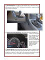
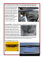
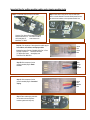
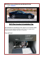
RX75 Plus INSTALLED RADAR & LASER DEFENSE SYSTEM
by BELTRONICS
RX75 Plus Corvette C-6 Installation Tips
We recommend bench assembling the entire system if you are a first time installer.
We also recommend reading the installation manual. Power can be applied and all
programming options selected on the bench or in the vehicle.
Power and Ground:
The fuse box is
located in the
passenger’s foot well
against the firewall.
Locate a switched fuse
and tap into the hot leg.
Ground for power can
also be found on the Bose
amplifier case. Pull the
carpet back to expose the
fuse box. The interface
(Letter Code F on the
Installation Manual) will fit
in the cavity under the
Bose unit.
Note: the optional
amplified speaker will also
get power from this area.
Display Controller, Remote Mute / Volume Adjust, Amplified Speaker (Optional HV model),
Concealed Display (Optional HV model): All wires from these components will run from the
driver side. Feed the wires through the console to the passenger side where the interface is
located. The small opening in the console for the wires is located towards the rear of the
console. The space is large enough for all wires.
The
Display
Controller
(Code letter E on the installation
manual) can be mounted on the lower
dash to the right of the steering wheel or
buried under the dash or in the center
console or anywhere on the HV model
after user preferences are programmed
if any. NOTE: If the owner wants laser
shifting enabled this must be performed
in programming mode in the Bands
MOD selection by setting SHFT in the
LSR selection column after all items are completely installed and power is restored.
The Remote Mute Button (Code letter H on the installation manual) should be located
within easy reach of the driver. NOTE: This button has three functions – please consult the
owner’s manual for explanation.
The Bi-Colored Concealed LED Display (optional HV model) can be mounted in the
“crease” of the instrument
cluster and upper dash as
shown. The LED comes
with a trim bezel –
a ¼ inch hole pulling the
LED through and attaching
trim and snapping it back in
the hole in almost any
location that is clearly
visible to the driver
will work.
The Amplified Speaker (optional and required for voice alerts) can be zip tied to the wiring
harness under the dash with the speaker pointing toward the driver’s lower legs. Use the
knurled knobs as “anchors” for the zip tabs (tip: for even greater volumes such as needed in
convertibles, open T-tops, etc., the speaker can be mounted above the dash).
Front Laser Shifters: The Front Laser
Shifters (Code letter B on the
installation manual) can be mounted
different ways. They can be mounted
inside the grill area as on the
Yellow Z06 with the supplied mount
brackets and 3M Scotch VHB 1 double
sided tape (follow surface preparation
and temperature instructions for the
VHB tape),
or they can be mounted outside the grill using
VHB double sided tape as shown on the black
car. Spread the shifters as far apart as possible
but maintain a clear view of the road ahead. The
shifters should be mounted as level as possible
(use the sight line on the short side of the shifter
as a level line) with the bubble lens on the top of
the front face. Remove the protective film from
the front face after installation. Feed the wires
towards the passenger side of the car under the
hood.
Front Radar Receiver: The Front Radar Receiver (Code letter A on the installation manual)
can be mounted inside the grill area using self taping hardware. Place the unit in the middle
and screw it to the plastic shroud. The unit can also be mounted inside under the hood
using double side tape and placed on the small ledge on the driver side as along as no
metallic parts obstruct the view forward (tip: do not mount radar receiver behind license
plate). The ledge is located behind the bumper.
Penetrating the Firewall: The wires from both front
shifters and the radar receiver should be run towards
the passenger side. The main wiring harness going
into the firewall will have a soft rubber boot around it.
You will need to disconnect and remove the battery
except on the Z06.
3M VHB (Very High Bond) tape 4979F Black, 1 inch x 36 yard 62.0 mil. thick. Conformable foam, multi-purpose acrylic
adhesive, black, clear PE film liner, double sided. VHB tape can be ordered through any automotive paint supple outlet that
carries 3M automotive products.
1
Take a small sharpened 1/8 inch metal rod and poke three holes through the rubber boot.
Cut the phone jack connectors off the wires and run thru the holes in the rubber boot.
This is much easier when taping the wires individually to the 1/8 inch metal rod and pushing
through. Once all wires are on the
other side of the firewall you will
need to cut the wires to length and
put new phone jack connectors on.
(Suggested replacement plugs and
the cut / crimper part numbers and
suppliers are noted on the
attached work instruction) Plug the
shifter wires into the supplied “Y”
connector and plug the Yconnector and radar receiver into
the proper interface location.
Rear Laser Shifter: The Rear Laser Shifter is (Code letter G on the installation manual)
mounted to the rear license plate. Using a
factory supplied square hole and the
same 1/8 inch metal rod as before cut the
phone jack connector off and run wire
towards the factory rubber boot located on
the right side of the trunk area. You will
need to remove the carpet cover from the
rear panel on the right side on the back.
Use the same method as the front shifters
and run the wire thru the rubber boot. Run
the wire towards the front passenger side to the interface, cut the wire to length, attach a
new modular plug and plug the rear laser into the correct interface location.
Rear Laser Shifter properly installed -
Interface: Ensure all jacks
are plugged into the interface.
Use cable ties on the mute
switch and amplified speaker
jacks. Place wiring into the
cavity and cover everything
back up.
Once the unit is tested put all body and interior components back in place.
Important tips for cutting modular cables and crimping modular jacks
Step 1: Cut modular cable in crimp tool as shown.
Step 2: Place cable in strip part of crimp tool and rotate
wire in a circular direction to remove outside jacket. Be sure
not to knick the insulation on the separate strand of wire.
Crimping Tool: Mouser Part Number 382-2094C
Mouser Electronics, Inc. Phone 800.346.6873
1000 North Main St.
www.mouser.com
Mansfield, TX 76063
Step 3A: Color sequence of wires placed in modular plug for
front shifters, rear shifters, and display module.
Modular Connector Digi-Key PN A9091-ND 4 Pos / 4 Cont
Digi-Key Corporation
Phone 800.344.4539
701 Brooks Ave South www.digikey.com
Thief River Falls, MN 56701
Step 3B: Color sequence of wires
placed in modular plug for Radar
receiver.
Step 3C: Color sequence of wires
placed in modular plug for Concealed
display.
Step 4: Place modular plug with cable
into location as shown. Squeeze
handles together until they stop.
Yellow
Red
Green
Blue
White
Orange
Blue
No wire
Yellow
Red
No wire
Blue