1
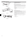
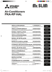
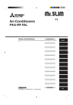
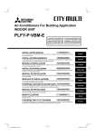
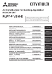
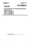
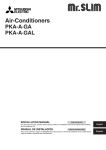
Air-Conditioners For Building Application INDOOR UNIT PKFY-P·VKM-E For use with the R410A, R407C & R22 English Contents 1. 2. 3. 4. Safety precautions.............................................................................................2 Installation location ............................................................................................3 Installing the indoor unit ....................................................................................3 Installing the refrigerant piping ..........................................................................7 5. Drainage piping work.........................................................................................9 6. Electrical work .................................................................................................10 7. Test run (Fig. 7-1) ............................................................................................ 11 1. Safety precautions X Before installing the unit, make sure you read all the “Safety precautions”. X Please report to your supply authority or obtain their consent before connecting this equipment to the power supply system. : Indicates an action that must be avoided. : Indicates that important instructions must be followed. : Indicates a part which must be grounded. : Indicates that caution should be taken with rotating parts. Warning: Describes precautions that must be observed to prevent danger of injury or death to the user. : Indicates that the main power switch must be turned off before servicing. : Beware of electric shock. : Beware of hot surface. Caution: Describes precautions that must be observed to prevent damage to the unit. After installation work has been completed, explain the “Safety Precautions,” use, and maintenance of the unit to the customer according to the information in the Operation Manual and perform the test run to ensure normal operation. Both the Installation Manual and Operation Manual must be given to the user for keeping. These manuals must be passed on to subsequent users. ELV : At servicing, please shut down the power supply for both the Indoor and Outdoor Unit. Warning: Carefully read the labels affixed to the main unit. Warning: Ask the dealer or an authorized technician to install the air conditioner. Install the unit at a place that can withstand its weight. Use the specified cables for wiring. Use only accessories authorized by Mitsubishi Electric and ask the dealer or an authorized technician to install them. • Do not touch the heat exchanger fins. • Install the air conditioner according to this Installation Manual. • Have all electric work done by a licensed electrician according to local regulations. • If the air conditioner is installed in a small room, measures must be taken to prevent the refrigerant concentration from exceeding the safety limit even if the refrigerant should leak. • The cut face punched parts may cause injury by cut, etc. The installers are requested to wear protective equipement such as gloves, etc. Caution: • Do not use the existing refrigerant piping, when use R410A or R407C refrigerant. • Use ester oil, either oil or alkylbenzene (small amount) as the refrigerator oil to coat flares and flange connections, when use R410A or R407C refrigerant. • Do not use the air conditioner where food, pets, plants, precision instruments, or artwork are kept. • Do not use the air conditioner in special environments. • • • • • • • • • • • • 2 Ground the unit. Install an leak molded case circuit braker, as required. Use power line cables of sufficient current carrying capacity and rating. Use only a molded case circuit braker and fuse of the specified capacity. Do not touch the switches with wet fingers. Do not touch the refrigerant pipes during and immediately after operation. Do not operate the air conditioner with the panels and guards removed. Do not turn off the power immediately after stopping operation. 2. Installation location PKFY-P·VKM-E 2.1. Outline dimensions (Indoor unit) (Fig. 2-1) B L Select a proper position allowing the following clearances for installation and maintenance. (mm) A 1170 29 5 PKFY-P·VKM-E C K 365 (mm) A B C D E Min. 100.5 Min. 22.4 Min. 48 Min. 250 Min. 220 F Air outlet: Do not place an obstacle within 1500 mm of the air outlet. M G Floor surface D F H Furnishing E I When the projection dimension of a curtain rail or the like from the wall exceeds 60 mm, extra distance should be taken because the fan air current may create a short cycle. * J J 1800 mm or greater from the floor surface (for high location mounting) I H K 108 mm or greater with left or rear left piping and optional drain pump installation L 550 mm or greater with optional drain pump installation G M Minimum 7 mm: 265 mm or greater with optional drain pump installation Fig. 2-1 3. Installing the indoor unit 1 2 3.1. Check the indoor unit accessories (Fig. 3-1) 3 The indoor unit should be supplied with the following accessories. PART NUMBER 4 5 ACCESSORY QUANTITY P63 P100 1 Mount board 1 2 Tapping screw 4 u 25 7 7 3 Felt tape 2 2 4 L-shaped connection pipe 1 1 5 Charge nut 1 1 LOCATION OF SETTING 1 Fix at the back of the unit 3.2. Installing the wall mounting fixture Fig. 3-1 3.2.1. Setting the wall mounting fixture and piping positions X Using the wall mounting fixture, determine the unit’s installation position and the locations of the piping holes to be drilled. 585 A 364 384.5 408.5 439 454 465.5 (mm) 314 110 3 60 60 10 0 10 314 110 H G F 454 439 408.5 384 364 517.4 585 0 54 PKFY-P·VKM-E Warning: Before drilling a hole in the wall, you must consult the building contractor. B 54 25 0 12.5 37.5 62.5 87.5 104.5 129.5 167 15.5 0 25 50 75 100 117 125 142 192 217 229.5 264 292 308.5 311 242 279.5 292 R3 D B Indoor unit C Bottom left rear pipe hole (ø75-ø80) D Bottom right rear pipe hole (ø75-ø80) E Knockout hole for left rear hole (75 × 480) F Bolt hole (4-ø9 hole) G Center measurement hole (ø2.5 hole) H Tapping hole (75-ø5.1 hole) I Hole centre J Align the scale with the line. K Insert scale. X Use a core drill to make a hole of 75-80 mm diameter in the wall in the piping direction, at the position shown in the diagram to the left. X The hole should incline so that the outside opening is lower than the inside opening. X Insert a sleeve (with a 75 mm diameter and purchased locally) through the hole. K J A Mount board 1 3.2.2. Drilling the piping hole (Fig. 3-3) 100 A 439 449.2 216.5 0 189 339 384 439 430.5 530.5 E 339 349.2 384 7.5 C PKFY-P·VKM-E (Fig. 3-2) I Note: The purpose of the hole’s inclination is to promote drain flow. Fig. 3-2 B A A Sleeve B Hole C (Indoors) C D D Wall E E (Outdoors) Fig. 3-3 3 3. Installing the indoor unit 3.2.3. Installing the wall mounting fixture X Since the indoor unit weighs near 21 kg, selection of the mounting location requires thorough consideration. If the wall does not seem to be strong enough, reinforce it with boards or beams before installation. X The mounting fixture must be secured at both ends and at the centre, if possible. Never fix it at a single spot or in any nonsymetrical way. (If possible, secure the fixture at all the positions marked with a bold arrow.) Warning: If possible, secure the fixture at all positions indicated with a bold arrow. Caution: • The unit body must be mounted horizontally. • Fasten at the holes marked with S as shown by the arrows. PKFY-P·VKM-E F PKFY-P·VKM-E (Fig. 3-4) C A Min. 90 mm (617.6 mm or greater with optional drain pump installation) B Min. 200 mm C Min. 70 mm (130 mm or greater with left, rear left, or lower left piping, and optional drain pump installation) D Fixing screws (4 × 25) 2 E Level F Fasten a thread to the hole. G Place the level against the horizontal reference line of the mount board and mount so that it is level. Hang a weight from the thread and align with V EPK of the mount board to permit leveling. H Weight I Mount board 1 E A B G I D H 3.3. When embedding pipes into the wall (Fig. 3-5) Fig. 3-4 B A • The pipes are on the bottom left. • When the cooling pipe, drain pipes internal/external connection lines etc are to be embedded into the wall in advance, the extruding pipes etc, may have to be bent and have their length modified to suit the unit. • Use marking on the mount board as a reference when adjusting the length of the embedded cooling pipe. • During construction, give the length of the extruding pipes etc some leeway. A B C D C Mount board 1 Reference marking for flare connection Through hole On-site piping 3.4. Preparing the indoor unit D * Check beforehand because the preparatory work will differ depending on the exiting direction of the piping. * When bending the piping, bend gradually while maintaining the base of the piping exiting portion. (Abrupt bending will cause misshaping of the piping.) Fig. 3-5 PKFY-P·VKM-E Attachment of L-shaped connection pipe 4 Right, left and rear piping (Fig. 3-6) PKFY-P·VKM-E A A Fig. 3-6 Fig. 3-7 A B C D E A B 1. Remove the flare nut and cap of the indoor unit. (Gas pipe only) 2. Apply refrigerating machine oil to the flare sheet surface. (Preparation on location) 3. Facing the direction in which the L-shaped connection pipe 4 will be removed, make a quick connection to the indoor unit flare connection opening. 4. Tighten the flare nut using a double open-end wrench. (Fig. 3-9) Tightening force: 68 to 82 N·m 5. Attach the charge nut 5 to the liquid pipe side joint portion, and check for leakage of the L-shaped connection pipe 4 connection portion. Remove the charge nut 5 after completion of the work. Tightening force: 34 to 42 N·m 6. Cover the flare connection portion with the pipe cover of the L-shaped connection pipe 4 so that it is not exposed. (Fig. 3-10) L-shaped connection pipe 4 Cut-off position (Straight pipe portion) Tightening direction Cover with pipe cover Cover the flare nut connection portion with the pipe cover. Lower piping (Fig. 3-7) Fig. 3-8 E C D Fig. 3-9 4 Fig. 3-10 1. Cut L-shaped connection pipe 4 at the position indicated in (Fig. 3-8). 2. Insert the flare nut that was removed earlier onto the straight pipe side of the cut L-shaped connection pipe 4 and then flare the end of the pipe. 3. Remove the flare nut and cap of the indoor unit. (Gas pipe only) 4. Apply refrigerating machine oil to the flare sheet surface. (Preparation on location) 5. Quickly connect the L-shaped connection pipe 4 that has been processed as described in part 2) to the indoor unit flare connection opening. 6. Tighten the flare nut using a double open-end wrench. (Fig. 3-9) Tightening force: 68 to 82 N·m 7. Attach the charge nut 5 to the liquid pipe side joint portion, and check for leakage of the L-shaped connection pipe 4 connection portion. Remove the charge nut 5 after completion of the work. Tightening force: 34 to 42 N·m 8. Cover the flare connection portion with the pipe cover of the L-shaped connection pipe 4 so that it is not exposed. (Fig. 3-10) 3. Installing the indoor unit Leakage check of the L-shaped connection pipe connection portion 1. Attach the charge nut 5 to the liquid pipe side joint portion. Tightening force: 34 to 42 N·m 2. Pressurize by filling with nitrogen gas from the charge nut. Do not pressurize to the current constant pressure all at once. Pressurize gradually. 1) Pressurize to 0.5 MPa, wait five minutes, and make sure the pressure does not decrease. 2) Pressurize to 1.5 MPa, wait five minutes, and make sure the pressure does not decrease. 3) Pressurize to 4.15 MPa and measure the surrounding temperature and refrigerant pressure. 3. If the specified pressure holds for about one day and does not decrease, the pipes have passed the test and there are no leaks. • If the surrounding temperature changes by 1°C, the pressure will change by about 0.01 MPa. Make the necessary corrections. 4. If the pressure decreases in steps (2) or (3), there is a gas leak. Look for the source of the gas leak. C Extraction and processing of the piping and wiring (Fig. 3-11) 1. Connection of indoor/outdoor wiring See page. 8. 2. Wrap the felt tape 3 in the range of the refrigerant piping and drain hose which will be housed within the piping space of the indoor unit. • Wrap the felt tape 3 securely from the base for each of the refrigerant piping and the drain hose. • Overlap the felt tape 3 at one-half of the tape width. • Fasten the end portion of the wrapping with vinyl tape. A D B E A Liquid pipe B Gas pipe Fig. 3-11 C Indoor/outdoor connection cable D Drain hose 1) E Felt tape 3 2) 3. Be careful that the drain hose is not raised, and that contact is not made with the indoor unit box body. Do not pull the drain hose forcefully because it might come out. Rear, right and lower piping (Fig. 3-12) A 1) Be careful that the drain hose is not raised, and that contact is not made with the indoor unit box body. Arrange the drain hose at the underside of the piping and wrap it with felt tape 3. 2) Securely wrap the felt tape 3 starting from the base. (Overlap the felt tape at one-half of the tape width.) B Fig. 3-12 A Cut off for right piping. B Cut off for lower piping. Left and left rear piping (Fig. 3-13) 4. Drain hose replacement See 6. Drainage piping work Be sure to replace the drain hose and the drain cap for the left and rear left piping. Dripping may occur if you forget to install or fail to replace these parts. C Drain cap C 1) Be careful that the drain hose is not raised, and that contact is not made with the indoor unit box body. 2) Securely wrap the felt tape 3 starting from the base. (Overlap the felt tape at one-half of the tape width.) 3) Fasten the end portion of the felt tape 3 with vinyl tape. D Cut off for left piping. 1) D 2) 3) Fig. 3-13 5 3. Installing the indoor unit C 3.5. Mounting the indoor unit 1. Affix the mount board 1 to the wall. 2. Hang the indoor unit on the hook positioned on the upper part of the mount board. Rear, right and lower piping (Fig. 3-14) 3. While inserting the refrigerant piping and drain hose into the wall penetration hole (penetration sleeve), hang the top of the indoor unit to the mount board 1. 4. Move the indoor unit to the left and right, and verify that the indoor unit is hung securely. 5. Fasten by pushing the bottom part of the indoor unit onto the mount board 1. (Fig. 3-15) * Check that the knobs on the bottom of the indoor unit are securely hooked into the mount board 1. 6. After installation, be sure to check that the indoor unit is installed level. A B Fig. 3-14 A Mount board 1 B Indoor unit C Hook D square hole C D B A Fig. 3-15 PKFY-P·VKM-E B A C Left and left rear piping (Fig. 3-16) 3. While inserting the drain hose into the wall penetration hole (penetration sleeve), hang the top of the indoor unit to the mount board 1. Giving consideration to the piping storage, move the unit all the way to the left side, then cut part of the packaging carton and wrap into a cylindrical form as illustrated in the diagram. Hook this to the rear surface rib as a spacer, and raise the indoor unit. 4. Connect the refrigerant piping with the site-side refrigerant piping. 5. Fasten by pushing the bottom part of the indoor unit onto the mount board 1. * Check that the knobs on the bottom of the indoor unit are securely hooked into the mount board 1. 6. After installation, be sure to check that the indoor unit is installed level. A Indoor unit B Packaging carton C Cut off D Wrap into a cylindrical form E Fasten with tape D E Fig. 3-16 6 4. Installing the refrigerant piping C B øA 45±2° 4.1. Connecting pipes (Fig. 4-1) • When commercially available copper pipes are used, wrap liquid and gas pipes with commercially available insulation materials (heat-resistant to 100 °C or more, thickness of 12 mm or more). • The indoor parts of the drain pipe should be wrapped with polyethylene foam insulation materials (specific gravity of 0.03, thickness of 9 mm or more). • Apply thin layer of refrigerant oil to pipe and joint seating surface before tightening flare nut. • Use two wrenches to tighten piping connections. • Use refrigerant piping insulation provided to insulate indoor unit connections. Insulate carefully. D .4~ R0 90°±0.5° A .8 R0 Fig. 4-1 A Flare cutting dimensions Copper pipe O.D. (mm) ø9.52 ø15.88 ø19.05 Flare dimensions øA dimensions (mm) 12.8 - 13.2 19.3 - 19.7 22.9 - 23.3 B Refrigerant pipe sizes & Flare nut tightening torque C Do not apply refrigerating machine oil to the screw portions. (This will make the flare nuts more apt to loosen.) D Be certain to use the flare nuts that are attached to the main unit. (Use of commercially-available products may result in cracking.) R407C or R22 Liquid pipe Gas pipe Tightening Tightening Pipe size O.D. Pipe size O.D. torque. torque. (mm) (mm) (N·m) (N·m) ODø9.52 (3/8”) 34 - 42 ODø15.88 (5/8”) 68 - 82 ODø9.52 (3/8”) 34 - 42 ODø19.05 (3-4”) 68 - 82* P63 P100 R410A Liquid pipe Gas pipe Tightening Tightening Pipe size O.D. Pipe size O.D. torque. torque. (mm) (mm) (N·m) (N·m) ODø9.52 (3/8”) 34 - 42 ODø15.88 (5/8”) 68 - 82 ODø9.52 (3/8”) 34 - 42 ODø15.88 (5/8”) 68 - 82 Flare nut O.D. Liquid pipe (mm) 22 22 Gas pipe (mm) 29 29 * Connect the joint with the following pipes: Liquid and gas pipes of P50, gas pipe of P100/P125. E Apply refrigerating machine oil over the entire flare seat surface. PKFY-P·VKM-E 295 1170 5 18.2 65 123 154 134 67 7.8 77 444 (A)* 482 (B) 585 (C) D E 65 65 65 7.8 77 67 365 G 77 87 1155 F F 77 87 71.2 Fig. 4-2 4.2. Positioning refrigerant and drain piping (Fig. 4-2) PKFY-P·VKM-E A Gas pipe * Indicates the condition with accessories mounted. B Liquid pipe C Drain hose D Left-side piping knockout hole E Right-side piping knockout hole F Lower piping knockout hole G Mount board 1 7 4. Installing the refrigerant piping A 4.3. Refrigerant piping (Fig. 4-3) Indoor unit 1. Remove the flare nut and cap of the indoor unit. 2. Make a flare for the liquid pipe and gas pipe and apply refrigerating machine oil (available from your local supplier) to the flare sheet surface. 3. Quickly connect the on site cooling pipes to the unit. 4. Wrap the pipe cover that is attached to the gas pipe and make sure that the connection join is not visible. 5. Wrap the pipe cover of the unit’s liquid pipe and make sure that it covers the insulation material of the on site liquid pipe. 6. The portion where the insulation material is joined is sealed by taping. B A Site-side refrigerant piping B Unit side refrigerant piping Fig. 4-3 4.3.1. Storing in the piping space of the unit (Fig. 4-4) PKFY-P·VKM-E 1. Wrap the supplied felt tape in the range of the refrigerant piping which will be housed within the piping space of the unit to prevent dripping. 2. Overlap the felt tape at one-half of the tape width. 3. Fasten the end portion of the wrapping with vinyl tape, etc. A Gas pipe B C C Indoor/outdoor connection cable A D Fig. 4-4 8 B Liquid pipe D Felt tape 3 5. Drainage piping work 5.1. Drainage piping work (Fig. 5-1) A D B C C E F J I G K C • Drain pipes should have an inclination of 1/100 or more. • For extension of the drain pipe, use a soft hose (inner dia. 15 mm) available on the market or hard vinyl chloride pipe (VP-16/O.D. ø22 PVC TUBE). Make sure that there is no water leakage from the connections. • Do not put the drain piping directly in a drainage ditch where sulphuric gas may be generated. • When piping has been completed, check that water flows from the end of the drain pipe. Caution: The drain pipe should be installed according to this Installation Manual to ensure correct drainage. Thermal insulation of the drain pipes is necessary to prevent condensation. If the drain pipes are not properly installed and insulated, condensation may drip on the ceiling, floor or other possessions. A Inclined downwards B Must be lower than outlet point H C Water leakage D Trapped drainage Fig. 5-1 E Air F Wavy 1 G The end of drain pipe is under water. 2 A H Drainage ditch a I 5 cm or less between the end of drain pipe and the ground. J Drain hose b 3 4 B K Soft PVC hose (Inside diameter 15 mm) or Hard PVC pipe (VP-16) * Bond with PVC type adhesive Preparing left and left rear piping (Fig. 5-2) 1 Remove the drain cap. • Remove the drain cap by holding the bit that sticks out at the end of the pipe and pulling. A A Drain cap 2 Remove the drain hose. • Remove the drain hose by holding on to the base of the hose a (shown by arrow) and pulling towards yourself b. 3 Insert the drain cap. • Insert a screwdriver etc into the hole at the end of the pipe and be sure to push to the base of the drain cap. 4 Insert the drain hose. • Push the drain hose until it is at the base of the drain box connection outlet. • Please make sure the drain hose hook is fastened properly over the extruding drain box connection outlet. A Fig. 5-2 B Hooks PKFY-P·VKM-E ¡ Storing in the piping space of the indoor unit (Fig. 5-3) D B C A E * When the drain hose will be routed indoors, be sure to wrap it with commercially available insulation. * Gather the drain hose and the refrigerant piping together and wrap them with the supplied felt tape 3. * Overlap the felt tape 3 at one-half of the tape width. * Fasten the end portion of the wrapping with vinyl tape, etc. A Gas pipe B Liquid pipe C Drain hose Fig. 5-3 D Indoor/outdoor connection wiring E Felt tape 3 ¡ Check of drainage (Fig. 5-4) 1. Open the front grille and remove the filter. 2. Facing the fins of the heat exchanger, slowly fill with water. 3. After the drainage check, attach the filter and close the grille. Fig. 5-4 9 6. Electrical work PKFY-P·VKM-E 6.1. Electrical work PKFY-P·VKM-E (Fig. 6-1) D G A F B E C M L A Elactrical box cover B Fixing screw H K Connection can be made without removing the front panel. 1. Open the front grille, remove the screw (1 piece), and remove the electrical parts cover. 2. Securely connect each wire to the terminal board. * In consideration of servicing, provide extra length for each of the wires. * Take care when using strand wires, because beards may cause the wiring to short out. 3. Install the parts that were removed back to their original condition. 4. Fasten each of the wires with the clamp under the electrical parts box. C Clamp KLM D Ground wire connection portion E MA remote control terminal board: (1, 2) do not have polarity F Transmission terminal board: (M1, M2, S) do not have polarity G Power supply terminal board (L, N, Earth). 55mm 12mm H Lead J Ground wire connection portion: Connect the ground wire in the direction illustrated in the diagram. L K Remote control cable N L Transmission cable M Power supply cable J 6.2. Power supply wiring • Power supply cable of appliance shall not be lighter than design 245 IEC 53 or 227 IEC 53. • Install an earth line longer than other cables. • A switch with at least 3 mm, 1/8 inch contact separation in each pole shall be provided by the air conditioner installation. Power cable size : more than 1.5 mm2 (3-core) [Fig.6-2] M Fig. 6-1 A Switch 16 A B Overcurrent protection 16 A C Indoor unit D Total operating current be less than 16 A E Pull box A B C E L N TB2 X Selecting non-fuse breaker (NF) or earth leakage breaker (NV). For breaker, means shall be provided to ensure disconnection of all active phase conductors of the supply. M1 M2 S TB5 Fig. 6-2 1 2 TB15 6.3. Types of control cables 1. Wiring transmission cables Types of transmission cable Cable diameter Length Shielding wire CVVS or CPEVS More than 1.25 mm2 Less than 200 m 2. M-NET Remote control cables Types of remote control cable Cable diameter Length Shielding wire MVVS More than 0.5 to 1.25 mm2 Add any portion in excess of 10 m to within the longest allowable transmission cable length 200 m. 3. MA Remote control cables Types of remote control cable Cable diameter Length 10 2-core cable (unshielded) 0.3 to 1.25 mm2 Less than 200 m 6. Electrical work B 1 A M1 M2 A M1 M2 S TB3 1 2 M1 M2 S TB5 1 2 TB15 TB5 TB15 C 2 B M1 M2 TB3 C A A M1 M2 S M1 M2 S TB5 TB5 C C 3 6.4. Connecting remote controller, indoor and outdoor transmission cables (Fig. 6-3) • Connect indoor unit TB5 and outdoor unit TB3. (Non-polarized 2-wire) The “S” on indoor unit TB5 is a shielding wire connection. For specifications about the connecting cables, refer to the outdoor unit installation manual. • Install a remote controller following the manual supplied with the remote controller. • Connect the remote controller’s transmission cable within 10 m using a 0.75 mm2 core cable. If the distance is more than 10 m, use a 1.25 mm2 junction cable. 1 MA Remote controller • Connect the “1” and “2” on indoor unit TB15 to a MA remote controller. (Nonpolarized 2-wire) • DC 9 to 13 V between 1 and 2 (MA remote controller) 2 M-NET Remote controller • Connect the “M1” and “M2” on indoor unit TB5 to a M-NET remote controller. (Nonpolarized 2-wire) • DC 24 to 30 V between M1 and M2 (M-NET remote controller) 3 Wireless remote controller(When installing wireless signal receiver) • Connect the wire of wireless signal receiver (9-pole cable) to CN90 of indoor con-troller board. • When more than two units are run under group control using wireless remote controller, connect TB15 each with the same number. • To change Pair No. setting, refer to installation manual attached to wireless remote controller. (In the default setting of indoor unit and wireless remote controller, Pair No. is 0.) A Terminal block for indoor transmission cable B Terminal block for outdoor transmission cable(M1(A), M2(B), (S)) C Remote controller D Wireless signal receiver E Wireless remote controller Fig. 6-3 6.5. Setting addresses (Fig. 6-4) A SWA 9 7 8 4 5 6 4 5 6 (10ths DIGIT) (1s DIGIT) SW14 F01 3456 2 3 2 3 7 8 0 1 BCDE 0 1 CN82 2 9 SW11 A 1 2 3 4 5 6 7 8 9 10 789 ON OFF SW12 CN43 3 2 1 SW1 No./ No. (BRANCH No.) (Be sure to operate with the main power turned OFF.) • There are two types of rotary switch setting available: setting addresses 1 to 9 and over 10, and setting branch numbers. 1 How to set addresses Example: If Address is “3”, remain SW12 (for over 10) at “0”, and match SW11 (for 1 to 9) with “3”. 2 How to set branch numbers SW14 (Series R2 only) Match the indoor unit’s refrigerant pipe with the BC controller’s end connection number. Remain other than series R2 at “0”. • The rotary switches are all set to “0” when shipped from the factory. These switches can be used to set unit addresses and branch numbers at will. • The determination of indoor unit addresses varies with the system at site. Set them referring to the Data Book. 6.6. Sensing room temperature with the built-in sensor in a remote controller Fig. 6-4 If you want to sense room temperature with the built-in sensor in a remote controller, set SW1-1 on the control board to “ON”. The setting of SW1-7 and SW18 as necessary also makes it possible to adjust the air flow at a time when the heating thermometer is OFF. 7. Test run (Fig. 7-1) B F E A ON/OFF button D B Test run display C Indoor temperature liquid line temperature display D ON/OFF lamp C E Power display TEST RUN COOL, HEAT F Error code display °C °C SIMPLE TEMP. MENU BACK MONITOR/SET PAR-21MAA ON/OFF ON/OFF FILTER DAY CLOCK A CHECK TEST OPERATION CLEAR Test run remaining time display G Set temperature button H Mode selection button I Fan speed button M TEST button HG 1 Turn on the power at least 12 hours before the test run. 2 Press the [TEST] button twice. “TEST RUN” liquid crystal display 3 Press the [Mode selection] button. Make sure that wind is blown out. 4 Press the [Mode selection] button and switch to the cooling (or heating) mode. Make sure that cold (or warm) wind is blown out. 5 Press the [Fan speed] button. Make sure that the wind speed is switched. 6 Check operation of the outdoor unit fan. 7 Release test run by pressing the [ON/OFF] button. Stop 8 Register a telephone number. The telephone number of the repair shop, sales office, etc., to contact if an error occurs can be registered in the remote controller. The telephone number will be displayed when an error occurs. For registration procedures, refer to the operation manual for the indoor unit. I M Fig. 7-1 11 This product is designed and intended for use in the residential, commercial and light-industrial environment. The product at hand is based on the following EU regulations: x x Low Voltage Directive 2006/95 EEC Electromagnetic Compatibility Directive 2004/108 EEC Please be sure to put the contact address/telephone number on this manual before handing it to the customer. HEAD OFFICE: TOKYO BLDG., 2-7-3, MARUNOUCHI, CHIYODA-KU, TOKYO 100-8310, JAPAN Authorized representative in EU: MITSUBISHI EUROPE.B.V HARMAN HOUSE, 1 GEORGE STREET, UXBRIDE, MIDDLESEX UB8 1QQ.U.K. RG79D346H01 Printed in Thailand