1
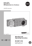
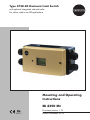
Type 3738-20 Electronic Limit Switch
with optional integrated solenoid valve
for valves used in on/off applications
Mounting and Operating
Instructions
EB 8390 EN
Firmware version 1.12
Edition December 2013
Definition of the signal words used in these mounting and operating instructions
DANGER!
indicates a hazardous situation which,
if not avoided, will result in death or
serious injury.
WARNING!
indicates a hazardous situation which,
if not avoided, could result in death or
serious injury.
2
NOTICE
indicates a property damage message.
Note:
Supplementary explanations, information and tips
EB 8390 EN
Contents
1
Important safety instructions...........................................................................6
2
Article code....................................................................................................7
3
Design and principle of operation...................................................................8
3.1Versions.......................................................................................................11
3.2Communication............................................................................................12
3.3
Safety-related information.............................................................................12
4
Technical data..............................................................................................14
4.1
Electronic limit switch....................................................................................14
4.2
Solenoid valve..............................................................................................16
5
Attachment..................................................................................................17
5.1Accessories..................................................................................................18
5.2
Attachment to linear actuators........................................................................19
5.2.1Preparations.................................................................................................19
5.2.2Attachment...................................................................................................20
5.3
Attachment to rotary actuators.......................................................................22
5.3.1Preparations.................................................................................................24
5.3.2Attachment...................................................................................................26
6
Connections.................................................................................................28
6.1
Pneumatic connections..................................................................................28
6.2
Supply pressure............................................................................................28
6.3
Electrical connection......................................................................................29
7
Operator controls and readings....................................................................33
7.1
Rotary pushbutton.........................................................................................33
7.2
SAMSON SSP interface.................................................................................33
7.3
Operating structure.......................................................................................34
8
Start-up.......................................................................................................38
8.1
Adapting the display direction.......................................................................38
8.2
Verifying readings on display........................................................................38
8.3
Determining the actuator type........................................................................39
8.4
Determining the direction of action.................................................................40
8.5
Determining the switching function of contacts.................................................40
EB 8390 EN
3
Contents
8.6
Adjusting the limit contacts............................................................................40
8.7Initialization.................................................................................................41
8.7.1
Start automatic initialization..........................................................................42
8.7.2
Start manual initialization..............................................................................43
8.8
Replacing an electronic limit switch.................................................................44
8.9
Zero/end position calibration........................................................................44
8.10
Reset to default settings..................................................................................45
9
Operation....................................................................................................46
9.1
Lock operation..............................................................................................46
9.2
9.2.1
9.2.2
9.2.3
Partial stroke test (PST)...................................................................................46
Defining the PST target range.........................................................................49
Starting the partial stroke test.........................................................................49
Configuration example based on PTO direction of action.................................50
9.3
Testing the contacts........................................................................................53
9.4
Testing the solenoid valve...............................................................................53
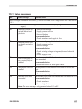
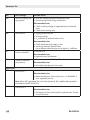
9.5Faults...........................................................................................................54
9.5.1
Status messages............................................................................................54
9.5.2
Error messages.............................................................................................54
9.5.3
Confirming status and error messages............................................................55
10
Maintenance, calibration and work on equipment.........................................55
10.1Maintenance................................................................................................55
11
Servicing explosion-protected devices...........................................................56
12
Firmware update (serial interface).................................................................56
13
Parameter list...............................................................................................57
13.1
Status messages............................................................................................61
13.2
Error messages.............................................................................................63
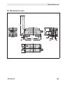
14
Dimensions in mm........................................................................................65
Index...........................................................................................................74
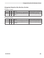
Assignment based on the direction of action..................................................79
4
EB 8390 EN
Firmware revisions
Firmware
Revisions
1.12
Changes to parameters and error messages (see section 13)
• Parameters renumbered due to parameters being added or removed.
Removed parameters:
– 'PST initialization' (the partial stroke test no longer needs to be initialized).
– Info: Rotary motions
New parameters:
– 'Actuator type' (rotary or linear actuator). See section 8.3.
– 'Switching function of contacts' (NO or NC contact). See section 8.5.
• Error messages renumbered due to error messages being removed.
Removed error messages:
– 'PST target range not reached'
– 'PST target range exceeded'
• The new parameter 'Actuator type' as well as the 'Actuator’s direction of action' parameter are locked after the electronic limit switch has been initialized. See sections
8.3 and 8.4.
• The actuator transit time monitoring (F4) depends on the value adjusted in 'Status
readout for actuator transit time (P13). This is adjustable between 0 (OFF) and 1800 s.
• The dead time is already included in the information parameters 'Actuator transit time
when the solenoid valve is de-energized' (P22) and 'Actuator transit time when the solenoid valve is energized' (P23).
• The monitoring of the rotary motion counter can be deactivated by configuring 'Maximum rotary motions' (P26) = OFF.
Changes to the partial stroke test (PST) (see section 9.2)
• The minimum pulse length at contact C is three seconds during partial stroke testing.
• The PST target range is made up of 'PST step end (P14) ± ½ 'PST tolerance band'
(P15).
• After a successfully completed partial stroke test, the assessment of the transit times
when the solenoid valve is de-energized' and energized ('PST transit time when the
solenoid valve is de-energized and 'PST transit time when the solenoid valve is energized'). In firmware version 1.01, only the duration of the entire test could be read.
• In the TROVIS-VIEW software, a diagram plotting the valve position against time while
the solenoid valve is de-energized and energized is shown (256 measuring points).
The data can be read out by connecting the device at the SSP interface to a PC.
Important safety instructions
1 Important safety instructions
For your own safety, follow these instructions concerning the mounting, start up and operation
of the electronic limit switch:
−− The device is to be mounted, started up or operated only by trained and experienced personnel familiar with the product. According to these mounting and operating instructions,
trained personnel is referred to as individuals who are able to judge the work they are assigned to and recognize possible dangers due to their specialized training, their knowledge
and experience as well as their knowledge of the applicable standards.
−− Explosion-protected versions of this device are to be operated only by personnel who has
undergone special training or instructions or who is authorized to work on explosion-protected devices in hazardous areas.
−− Any hazards that could be caused by moving parts are to be prevented by means of the
appropriate measures.
−− For use within hazardous areas, the Special Conditions mentioned in the EC type examination certificate and its addenda must be observed.
−− If inadmissible motions or forces are produced in the pneumatic actuator as a result of the
supply pressure level, it must be restricted using a suitable supply pressure reducing station.
To avoid damage to any equipment, the following also applies:
−− Proper shipping and storage are assumed.
−− Do not ground electric welding equipment near to the electronic limit switch.
6
Note:
The device with a CE marking fulfills the requirements of the Directive 2004/108/EC.
EB 8390 EN
Article code
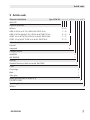
2 Article code
Electronic Limit Switch
Type 3738-20- x x x 1 x 0 0 x x x x 0 x
With LCD
Explosion protection
Without
0 0 0
ATEX: II 2G Ex ia IIC T6; II 2D Ex IIIC T80°C IP 66
1 1 0
ATEX: II 2G Ex eb[ia] IIC T4; II 2D Ex tb IIIC T80°C IP 66
3 1 0
GOST: 1Ex ia IIC T6/T5/T4 Ga X; Ex tb IIIC T80°C Db X
1 1 3
GOST: 1Ex e [ia] IIC T4 Gb X; Ex tb IIIC T80°C Db X
3 1 3
0
Solenoid valve
External
0
Integrated
4
Company version
SAMSON
0
AIR TORQUE
1
Housing
Standard aluminum, black structured, RAL 9005
1
Cover
Gray beige
0
Black
1
Silver gray
3
Safety approval (refer to section 3.3)
TÜV/IEC 61508
2
Special applications
Without
EB 8390 EN
0
7
Design and principle of operation
3 Design and principle of operation
The Type 3738-20 Electronic Limit Switch can
replace conventional solenoid valves and limit switches used for the automation of on/off
valves without the need to change the wiring
or signal level. Major features of the electronic limit switch include:
−− Unification of the functions featured in limit switches and a solenoid valve in one
housing
−− Power supplied in a two-wire system from
the connection of contact A, without the
need for an additional power supply
−− Non-contact sensing of the rotation angle
by a magnetoresistive sensor system
−− Integrated diagnostics with partial stroke
testing (PST)
−− Suitable for use in safety-instrumented systems up to SIL 2 (single device) and SIL 3
(redundant configuration). Refer to section
3.3 on page 12.
Fig. 2 and Fig. 3
The electronic limit switch is designed for attachment to linear and rotary actuators. The
travel is measured without contact using a
magnet (on a screw) positioned centrically
on the actuator shaft. The screw with magnet does not need to be adjusted. The AMR
(anisotropic magnetoresistive) sensor located
in the device together with the measuring electronics (1) can detect the directional change
of the applied magnetic field and, as a result,
sense the movement of the actuator.
The actuator is actuated by a solenoid valve
(7) which converts the binary signal issued by
electric control equipment (6) into a binary
pressure signal.
The electronic limit switch has four NAMUR
contacts: the limit switch for fail-safe position
(contact A, 13) and the limit switch for operating position (contact B, 14) issue a limit signal when the valve reaches the corresponding end position. Contact C indicates that a
third limit has been reached or that the target range has been reached during the partial
stroke test. The switching response of the contacts can be adjusted within the travel range.
The fault alarm contact St (16) indicates the
generation of any status and error messages.
An electronic limit switch version for an external solenoid valve (Fig. 2) is available for
higher air capacities required by large actuators. The principle of operation is the same.
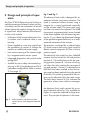
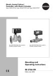
Fig. 1: Valve assembly with electronic limit
switch (version with integrated solenoid
valve)
8
EB 8390 EN
Design and principle of operation
12
Electronic limit
switch
Power
Supply
SSP
interface
13
A
10
9
14
B
15
3
C
5
4
16
St
6
Signal for solenoid
valve: V1 or V3
11
7
8
2
1
Actuator
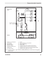
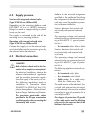
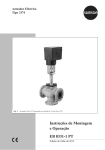
1 AMR sensor with electronics
2 A/D converter
3Microcontroller
4 Electrical insolation
5 Electrical insolation
6 Actuation of solenoid valve
7 Solenoid valve
8 Air capacity booster
9
10
11
12
13
14
15
16
Display
Rotary pushbutton (on-site operation)
LED for solenoid valve
Internal supply
NAMUR contact A (limit switch for fail-safe position)
NAMUR contact B (limit switch for operating position)
NAMUR contact C (signal when PST target range reached)
NAMUR contact St (fault alarm contact)
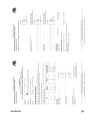
Fig. 2: Schematic diagram – Type 3738-20-xxx1400xxx000 Electronic Limit Switch with integrated
solenoid valve
EB 8390 EN
9
Design and principle of operation
12
Electronic limit
switch
Power
Supply
SSP
interface
13
A
10
9
14
B
15
3
C
5
4
16
St
6
Signal for solenoid
valve: V1
11
2
V2
7
1
Actuator
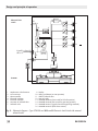
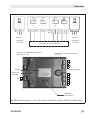
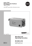
1 AMR sensor with electronics
2 A/D converter
3Microcontroller
4 Electrical insolation
5 Electrical insolation
6 Actuation of solenoid valve
7 Solenoid valve
9 Display
10 Rotary pushbutton (on-site operation)
11 LED for solenoid valve
12 Internal supply
13 NAMUR contact A (limit switch for fail-safe position)
14 NAMUR contact B (limit switch for operating position)
15 NAMUR contact C (signal when PST target range reached)
16 NAMUR contact St (fault alarm contact)
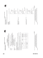
Fig. 3: Schematic diagram – Type 3738-20-xxx1000xxxx00 Electronic Limit Switch with external
solenoid valve
10 EB 8390 EN
Design and principle of operation
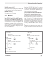
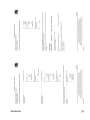
NAMUR contacts A, B, C
The contacts can be configured as either NO
or NC contacts. See Fig. 4 and section 8.5.
NAMUR contact St
This contact is a NC contact.
3.1 Versions
Type 3738-20-xxx1400xxx000 Electronic
Limit Switch with integrated solenoid valve
The electronic limit switch with integrated solenoid valve form a compact unit together with
a pneumatic actuator, which is easy to mount.
The 3/2-way or 5/2-way function of the solenoid valve is selected by changing the position of a molded seal.
NC contact
No response
Metal tag outside the inductive field
Based on VDI/VDE 3845, level 2, its version
can be mounted onto Pfeiffer Type 31b Rotary Actuators. The need for additional pneumatic connections is eliminated.
Type 3738-20-xxx1000xxxx00 Electronic
Limit Switch for external solenoid valve
The electronic limit switch for an external solenoid valve allows switching capacities up to
max. 18 W at 24 V DC, meaning all common
solenoid valves, even the Ex e versions, can
be combined with the electronic limit switch.
This version is suitable for rotary actuators according to VDI/VDE 3845, level 1. See Fig.
4.
Changes to the electronic limit switch's settings do not effect the external solenoid valve.
NO contact
Reponds
Metal tag inside the inductive field
[mA]
[mA]
2.1
2.1
No response
Metal tag outside the inductive
field
Reponds
Metal tag inside the inductive field
1.2
1.2
Wire break
0.05
Wire break
0.05
Fig. 4: NO and NC contacts
EB 8390 EN
11
Design and principle of operation
3.2 Communication
The electronic limit switch can be configured
with SAMSON's TROVIS-VIEW Configuration
and Operator Interface.
The electronic limit switch has for this purpose
a SAMSON SSP interface to allow the RS-232
or USB port of a computer to be connected to
it over a serial interface adapter cable.
The TROVIS-VIEW software enables the user
to easily configure the electronic limit switch as
well as view and document process parameters on a computer.
See Table 1 on page 18 for order numbers.
Note:
TROVIS-VIEW provides a uniform user
interface that allows users to configure
and parameterize various SAMSON
devices using device-specific database modules. The Type 3738-20 device module can be downloaded free
of charge from our website (www.
samson.de) at Services > Software >
TROVIS-VIEW. Further information on
TROVIS-VIEW (e.g. system requirements) is available on our website and
in the Data Sheet u T 6661 EN.
3.3 Safety-related information
The Type 3738-20 Electronic Limit Switch
was developed to meet the requirements stipulated in IEC 61508. The safety-related data are listed in the Manufacturer’s Declaration HE 1163.
The conformity of the development process
and the performed FMEDA as well as the
12 statements in the Manufacturer’s Declaration
HE 1163 are certified by TÜV Rheinland Industrie Service GmbH in the Certificate 968/
EL 485.01/09 dated 9 November 2009.
Type 3738-20-xxx1000xxxx00 in combination with an external solenoid valve
The forwarding of the switching voltage for the external solenoid valve by the
Type 3738-20-xxx1000xxxx00 Electronic
Limit Switch has the same quality as wiring
and does not lead to a change in the safetyrelated data of the circuit.
Safety-related assumptions
Safety-related end position monitoring
All switching contacts of the Type 3738-20
Electronic Limit Switch behave as stipulated
in IEC 60947-5-6 and are suitable for use in
safety-instrumented systems up to SIL 2 (single
device) and SIL 3 (redundant configuration)
according to TÜV/IEC 61508. The contacts
can be used either as NC or NO contacts.
Their switching states are indicated according
to IEC 60947-5-6. Contact A is assigned to
the end position for the fail-safe position (limit switch for fail-safe position). The fail-safe
position is the end position to which the single-acting actuator is moved by the springreturn mechanism when the solenoid valve is
de-energized.
Emergency venting
When the optional integrated solenoid valve
is used, the electronic limit switch discharges its pneumatic output to the atmosphere
when the solenoid valve is de-energized. This
causes the mounted actuator to be vented.
The function is suitable for use in safety-inEB 8390 EN
Design and principle of operation
strumented systems up to SIL 2 (single channel) and SIL 3 (redundant configuration) according to IEC 61508.
Note:
Safety-related end position monitoring and emergency venting work independently from one another to meet
the device design requirements to conform with SIL.
Requirements
−− Short mean time to repair compared to
the average rate of demand
−− Normal exposure to industrial environment and fluids
−− The user is responsible for ensuring that
the device is used as intended.
Useful lifetime
−− The correct setting of all parameters must
be verified before every start-up.
Proof testing
All switching contacts need to be activated for
the proof test. This can be done by:
−− Using the mounted actuator to move the
valve to the end position
−− Simulating the outputs using P19 parameter. Refer to section 9.4.
During the proof test, check that the outputs
switch properly.
Intended use
The specifications and information in the data sheet and in these instructions must be observed.
Note concerning diagnosis of connected solenoid valve and actuator
According to IEC 61508-2, section 7.4.9.5,
a useful lifetime of 8 to 12 years can be assumed. Other values can be used based on
the user’s experience.
The diagnostics functions performed in the
device, e.g. actuator transit time monitoring,
are suitable for diagnosis of connected devices, such as solenoid valve, pneumatic actuator and valve.
Notes concerning diagnostics
Repairs
−− A diagnostics are performed cyclically inside the device. Critical errors (device error E9) are indicated by contact B as wire
breakage according to IEC 60947-5-6.
Existing errors must be remedied as described in these Mounting and Operating Instructions. If this is not possible, the
electronic limit switch must not be used in
safety loops.
−− The proper functioning of the display can
be verified over P3 parameter. Refer to
section 8.2.
EB 8390 EN
Devices which are used in safety-instrumented
systems must be repaired by the manufacturer.
13
Technical data
4 Technical data
4.1 Electronic limit switch
Electronic Limit Switch Type
3738-20-xxx1400xxx000
Version
With integrated solenoid valve With external solenoid valve
Permissible range of rotation
Min.: 0 to 30° Max.: 0 to 170°
Communi- Local communication
cation
Software
SAMSON SSP interface with serial interface adapter
Supply air Supply air
2.4 to 8 bar
Air quality
3738-20-xxx1000xxxx00
TROVIS-VIEW with database module 3738-20
Acc. to ISO 8573-1
Max. particle size and density:
Class 4
Oil content: Class 3
Moisture and water: Class 3
Pressure dew point: at least
10 K beneath the lowest
ambient temperature to be
expected
Same as specifications of the
solenoid valve manufacturer
Electric power supply
Powered over contact A acc. to IEC 60947-5-6 (e.g. NAMUR
isolating switch amplifier)
Permissible ambient temperature
–25 to 80 °C
The limits specified in the examination certificate additionally apply.
Metal cable glands must be used for ambient temperatures below –20 °C.
Influences
Temperature
±0.7 %/90° angle above the permissible temperature range
Influence of vibrations
≤ 0.25 % up to 2500 Hz and 4 g according to IEC 770
–40 to 80 °C
Electromagnetic compatibility
Complying with EN 61000-6-2, EN 61000-6-3, EN 61326-1
and NAMUR Recommendation NE 21
Electrical connections
Four M20 x 1.5 cable glands for 6 to 12 mm clamping range,
screw terminals for 0.2 to 2.5 mm² wire cross-sections
Explosion protection
ATEX:
ATEX:
GOST:
GOST:
NEPSI:
14 Type 3738-20-000…
Type 3738-20-110…
Type 3738-20-310…
Type 3738-20-113…
Type 3738-20-313…
Type 3738-20-812...
Without
II 2G Ex ia IIC T6; II 2D Ex ia IIIC T80°C IP66
II 2G Ex eb[ia] IIC T4; II 2D Ex tb IIIC T80°C IP66
1Ex ia IIC T6/T5/T4 Ga X; Ex tb IIIC T80°C Db X
1Ex e [ia] IIC T4 Gb X; Ex tb IIIC T80°C Db X
Ex nL IIC T4~T6 Gc; Ex nA IIC T4~T6 Gc; DIP A22 Ta, T4~T6
EB 8390 EN
Technical data
Electronic Limit Switch Type
3738-20-xxx1400xxx000
Version
With integrated solenoid valve With external solenoid valve
Degree of protection
IP 66
Safety
approval
Safety-related end
position monitoring
The limit switches are suitable for use in safety-instrumented
systems up to SIL 2 (single channel) and SIL 3 (redundant configuration) according to IEC 61508. For further details, refer to
section 3.3 Safety-related information.
Emergency venting
See section 3.3 Safety-related
information.
Housing
Die-cast aluminum EN AC-AlSi12(Fe) (EN AC-44300) acc. to
DIN EN 1706, powder paint coated
Housing cover
PC
Cover gasket
PU
Indicator wheel
PC
Magnet material
Hard ferrite
Materials
Weight
Approx. 1.2 kg
3738-20-xxx1000xxxx00
Same as specifications of the
solenoid valve manufacturer
Approx. 1.0 kg
Contacts · Only for connection according to IEC 60947-5-6, reverse polarity protection, galvanic
isolation
Switching function
Switching
contacts
NC contact
NO contact
No response/no fault
≥ 2.1 mA
≤ 1.2 mA
Response/fault indication
≤ 1.2 mA
≥ 2.1 mA
Hysteresis
Contacts
1%
Contact A
Limit switch for fail-safe
position (solenoid valve
de-energized)
Contact B
Limit switch for operating
position (solenoid valve
energized)
PTO (power to open): Responds when the valve moves through
the switching contact towards the lower end position (P7)
PTC (power to close): Responds when the valve moves through
the switching contact towards the upper end position (P8)
PTO (power to open): Responds when the valve moves through
the switching contact towards the upper end position (P8)
PTC (power to close): Responds when the valve moves through
the switching contact towards the lower end position (P7)
Signal for wire breakage according to IEC 60947-5-6
Contact C
Responds when the valve reaches the PST target range*
Signal when target range
reached during partial
stroke test
*PST target range =
'PST step end' (P14) ± ½ 'PST tolerance band' (P15)
EB 8390 EN
15
Technical data
Electronic Limit Switch Type
3738-20-xxx1400xxx000
Version
With integrated solenoid valve With external solenoid valve
Contacts
Contact C
Limit contact for
intermediate position
Contact St
Fault alarm contact
Current specifications when contact A
is not connected
3738-20-xxx1000xxxx00
PTO (power to open): Responds when the valve moves through
the switching contact towards the operating position (P14)
PTC (power to close): Responds when the valve moves through
the switching contact towards the fail-safe position (P14)
Responds when a status message or error message is
generated (always NC contact)
Contact B: I = 50 µA (wire breakage)
Contact C: I = 1.2 mA
Contact St: I = 1.2 mA
4.2 Solenoid valve
Integrated solenoid valve (Type 3738-20-xxx1400xxx000)
Current draw
I=
– 3.325 mA (corresponding to 14.4 mA at 24 V)
Version
3/2-way or 5/2-way function
Function determined by the position of the molded seal
KVS coefficient
0.32
Service life
1,000,000 switching cycles
Temp. range (operation)
–25 to +80 °C
Switching
voltage
Nom. voltage
24 V DC, reverse polarity protection, galvanic isolation
Signal 0
When the voltage falls below 15 V DC
Signal 1
Min. 18 V DC
Switching capacity
24 V DC, 15.2 mA (0.36 W)
Duty cycle
100 %
Static destruction limit
32 V DC
External solenoid valve (Type 3738-20-xxx1000xxxx00)
Read manufacturer’s specifications!
24 V DC, max. 18 W
Switching
voltage
Signal 0
When the voltage falls below 15 V DC
Signal 1
Min. 18 V DC
Static destruction limit
16 32 V DC
EB 8390 EN
Attachment
5 Attachment
DANGER!
−−Electrostatic charging
Due to the high surface resistance of
the enclosure cover (RIsol. ≥ 109 Ω),
installation and maintenance on the
equipment must be performed in
such a way that electrostatic charging cannot occur.
−−Mechanical effects
In areas where damage to the housing can be expected due to mechanical influences, the housing must be
protected by an additional cover.
NOTICE
Observe the following instructions to
avoid damaging the electronic limit switch:
−−Use only the accessories listed in the
Table 1 to mount the electronic limit switch!
−−Observe the shaft height of the actuator on mounting the electronic limit
switch on rotary actuators!
−−Combustible dust atmospheres
The electronic limit switch complies with the requirements for type
of protection Ex tb as the enclosure
(housing) is designed according to
EN 60079-31. The housing has the
degree of protection IP 66 according
to IEC 60529.
WARNING!
Mount the electronic limit switch, keeping the following sequence:
−−Mount the electronic limit switch on
the actuator. Refer to section 5.2
and 5.3.
−−Connect the supply air. Refer to section 6.1 and 6.2.
−−Connect the electrical power. Refer
to section 6.3.
−−Perform the start-up settings. Refer
to section 8.
EB 8390 EN
17
Attachment
5.1 Accessories
Table 1: Accessories
Order no.
Attachment to linear
actuators (NAMUR
attachment)
Version with integrated solenoid valve
G ¼ 1402-0540
Version with integrated solenoid valve
¼ NPT 1402-0541
Version for external solenoid valve
G ¼ 1402-0542
Version for external solenoid valve
¼ NPT 1402-0543
Plus mounting parts for Type 3271 Actuator
Version up to 700 cm²
Attachment to rotary
actuators acc. to VDI/
VDE 3845, fixing level 1
(2010)
Cable glands (M20 x 1.5)
TROVIS-VIEW Configuration and Operator Interface
software
18 –
1400-60 and 2800-120 versions
1402-0544
2800-30 and 2800-60 versions
1402-0545
Attachment (20 mm shaft height)
1400-9859
Attachment (30 mm shaft height)
1400-9860
Attachment (50 mm shaft height)
1400-9861
Attachment (50 mm shaft height, 88 mm shaft diameter),
e.g. Pfeiffer Type 31b, size 2000
1402-0332
Standard mounting platform (black)
G ¼ 1380-1266
Standard mounting platform (black)
¼ NPT 1380-1268
Mounting platform with piping as required
G ¼ 1380-1738
Mounting platform with piping as required
¼ NPT 1380-1739
Nickel-plated brass
1880-4875
Stainless steel 1.1305
8808-0160
Version for Ex i: black plastic
8808-0180
Version for Ex i: blue plastic
8808-0181
TROVIS-VIEW with device module 3738-20 (free download from www.
samson.de)
Serial interface adapter (SAMSON SSP interface to
RS-232 port on a PC)
1400-7700
Isolated USB interface adapter (SAMSON SSP interface
to USB port on a PC)
1400-9740
EB 8390 EN
Attachment
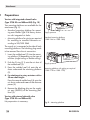
5.2 Attachment to linear actuators
2. Push the O-ring (3.1) onto the air duct of
the molded seal (3).
3. Fasten the electronic limit switch (1) to the
mounting unit (2) using the two screws
mounted on the electronic limit switch as
shown in Fig. 5.
The electronic limit switch is mounted to linear
actuators according to IEC 60534-6 (NAMUR
attachment).
Required accessories: see Table 1
4. Remove the stopper on the supply air port
(SUPPLY, 2.1) of the mounting unit (2).
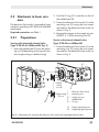
5.2.1 Preparations
Version with external solenoid valve
(Type 3738-20-xxx1000xxx00)
Version with integrated solenoid valve
(Type 3738-20-xxx1400xxx000) (Fig. 5)
1. Fasten the electronic limit switch (1) to the
mounting unit (2) using the two screws
mounted on the electronic limit switch as
shown in Fig. 5.
1. Insert the molded seal (3) into the mounting unit (2) depending on the type of actuator (single-acting or double-acting).
2.1
Doubleacting
5/2-way
1
3.1
3
2
1
Single-acting 2
3/2-way
2.1
3
3.1
Y1
Y2
Electronic limit switch
Mounting unit
Supply air port
Molded seal
O-ring
Output signal pressure
Opposing signal pressure
Fig. 5: Preparations for mounting the electronic limit switch with integrated solenoid valve
EB 8390 EN
19
Attachment
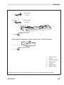
5.2.2 Attachment
Mounting to Type 3271 Actuators with
1400 and 2800 cm² actuator areas and
with 200 mm rated travel (Fig. 7 2 )
Fasten the follower plate (7.4) on the outer
holes to the stem connector (9) of the actuator using the screws (7.5).
Use the lever (5) underneath the mounting
unit (2) and the pin (6) on the lever to adapt
the electronic limit switch to the linear actuator used.
Mounting to Type 3271 Actuators with
2800 cm² actuator area and with 50,
100 or 200 mm rated travel (Fig. 7 3 )
Fasten the bracket (8) onto the stem connector (9) of the actuator using the screws
(8.2).
Fasten the follower plate (7.1) together
with the pins (8.1) on the middle holes
to the bracket (8) using the washers (7.2)
and screws (7.3).
Table 2: Travel table
Actuator
size [cm²]
Rated
travel
[mm]
Lever
Recommended pin position
120 to 350
15
M
35
700
15/30
M
50
1400
60
L
100
2800
120
XL
200
2800
30
M
50
2800
60
L/XL
100/200
The electronic limit switch is equipped with the
lever M (pin position 35) as standard.
Levers L and XL are included in the mounting
parts 1402-0544 or 1402-0545.
1. Select lever (5) according to Table 2.
5. Fasten the mounting unit (2) on the actuator using the screw (4), making sure that
the follower pin (6) comes to rest in the slot
of the follower plate (7.1/7.4).
6. Electronic limit switch with integrated solenoid valve: connect supply air to supply
air port (SUPPLY, 2.1).
2. Insert the follower pin (6) into the pin position according to Table 2 of the lever (5).
Fasten tight using the washers and nuts
(Fig. 6).
3. Place the lever (5) on the shaft of the
mounting unit (2) and screw tight using
the disk spring (5.1) and nut (5.2).
4. Mounting to actuators with 120 to
700 cm² actuator areas (Fig. 7 1 ):
Fasten the follower plate (7.1) on the middle holes of the stem connector (9) of the
actuator using the washers (7.2) and
screws (7.3).
20 6
6.2
5
5.2
5.1
6.1
6.2
5
5.1
5.2
6
6.1
6.2
Lever
Disk spring
Nut
Follower pin
Washer
Nut
Fig. 6: Fastening the follower pin on the lever
EB 8390 EN
Attachment
1
2
2.1
4
5
5.1
5.2
6
6.1
6.2
7.1
7.2
7.3
7.4
7.5
8
8.1
8.2
9
Electronic limit switch
Mounting unit
Supply air port (SUPPLY)
Screw
Lever
Disk spring
Nut
Follower pin
Washer
Nut
Follower plate
Washer
Screws
Follower plate
Screws
Bracket
Pin
Screws
Stem connector
9
7.1
7.2
7.4
8
7.3
1
6
7.5
7.1
5
2
8.2
8.1
7.2
6
7.3
3
5
2
4
6
5
2.1
1
Fig. 7: Mounting the electronic limit switch on linear actuators
EB 8390 EN
21
Attachment
5.3 Attachment to rotary actuators
Fig. 8
The electronic limit switch is mounted on rotary actuators according to VDI/VDE 3845,
level 1 (2010). The version with integrated
solenoid valve can be directly mounted to a
Pfeiffer Type 31b Rotary Actuator.
Required accessories: see Table 1
22 EB 8390 EN
Attachment
Versions with integrated solenoid valve
(Type 3738-20-xxx1400xxx000)
Version for external solenoid valve
(Type 3738-20-xxx1000xxxx00)
Actuator surface
M6
B
Actuator surface
Ø 5.5
30
*C
A
Shaft height B
[mm]
20
30
50
Distance between holes A
[mm]
80
80/130
130
Fig. 8: Mounting to rotary actuators according to VDI/VDE 3845, level 1 (2010)
EB 8390 EN
23
Attachment
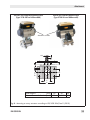
.1 Preparations
Version with integrated solenoid valve
(Type 3738-20-xxx1400xxx000) (Fig. 10)
Two mounting platforms are available for the
attachment (Fig. 9):
−− Standard mounting platform for mounting onto Pfeiffer Type 31b Rotary Actuator with integrated air holes
−− Mounting platform for piping as required
for mounting to standard actuators according to VDI/VDE 3845
Supply pressure
Standard mounting platform
(1380-1266 or 1380-1268)
The supply air is connected at the side of both
mounting platforms. The blanking plug needs
to be removed from the air connection.
1. Insert the molded seal (3) into the mounting platform (2) depending on the type of
actuator (single-acting or double-acting).
2. Push the O-ring (3.1) onto the air duct of
the molded seal (3).
Supply pressure
3. Press the molded seal (4) onto the air
ducts underneath the mounting platform
(2).
Mounting platform with piping as required
(1380-1738 or 1380-1739)
4. For attachment to rotary actuators with a
50 mm shaft height:
Press the second molded seal (4) onto the
air ducts underneath one of the distance
pieces (5).
5. Remove the blanking plug on the supply
air port (SUPPLY) of the mounting platform (2).
Version with external solenoid valve
(Type 3738-20-xxx1000xxx00)
No preparation is necessary.
24 Fig. 9: Mounting platform
EB 8390 EN
Attachment
Single-acting
3/2-way
3.1
3
Double-acting
5/2-way
2
4
Distance piece for attachment to rotary actuators with a 50 mm shaft height
5
4
1
2
3
3.1
4
5
Electronic limit
switch
Mounting platform
Molded seal
O-ring
Molded seal
Distance piece
Fig. 10:Preparations for mounting the electronic limit switch with integrated solenoid valve
EB 8390 EN
25
Attachment
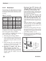
5.3.2 Attachment
The attachment depends on the shaft height of
the rotary actuator upon which the electronic
limit switch is to be mounted (Fig. 11).
Shaft height
20 mm
30 mm
50 mm
Screw with
magnet (6)
SW 24,
30 mm
SW 24,
20 mm
SW 24,
20 mm
Fillister-head
screws (10)
M5x16
M5x16
M5x40
1. Attachment to rotary actuators with a 20
or 30 mm shaft height: Place the spacers (11) on the inner holes of the actuator.
Attachment to rotary actuators with a
50 mm shaft height: Place the distance
pieces (5) on the rotary actuator.
Note concerning electronic limit switches with integrated solenoid
valve:
Place the distance piece including inserted molded seal (4) over the air
ducts of the actuator.
2. Fasten the mounting platform (2) on the
rotary actuator:
−− Version with integrated solenoid
valve: screws 10a and 10b
−− Version for external solenoid valve:
screws 10a
Note concerning electronic limit switches with integrated solenoid
valve:
Fasten the mounting platform (2),
making sure that the air ducts located
on the rotary actuator and the mounting platform are properly aligned.
3. Attachment to rotary actuators with a
20 mm shaft height: Place the adapter
(7) and indicator wheel (8) one after the
other onto the actuator shaft.
Attachment to rotary actuators with a
30 or 50 mm shaft height: Place the indicator wheel (8) onto the actuator shaft.
4. Insert plate (9) into the indicator wheel
(8).
NOTICE
Do not exceed the maximum torque of
8 Nm when fastening the screw with
magnet (6).
5. Fasten the screw with magnet (6) onto the
actuator shaft.
6. Bend the two flaps on the plate (9) towards the width flats of the screw with
magnet (6).
7. Place the electronic limit switch on the
mounting platform (2) as shown in Fig. 11
and fasten it using the two screws mounted on the device.
8. Electronic limit switch with integrated solenoid valve: connect supply air to supply
air port (SUPPLY, 2.1).
26 EB 8390 EN
Attachment
6
6
6
9
9
9
8
8
8
7
10b
10b
10a
10a
10a
2
2
2
2.1
2.1
2.1
11
11
5
20 mm shaft height
1
2
2.1
5
6
30 mm shaft height
Electronic limit switch
Mounting platform
Supply air port (SUPPLY)
Distance piece
Screw with magnet
7
8
9
10
11
50 mm shaft height
Adapter
Indicator wheel
Plate
Fillister-head screws
Spacer
Fig. 11:Mounting the electronic limit switch on rotary actuators
EB 8390 EN
27
Connections
6 Connections
WARNING!
Mount the electronic limit switch, keeping the following sequence:
−−Mount the electronic limit switch on
the actuator. Refer to section 5.2
and 5.3.
−−Connect the supply air. Refer to section 6.1 and 6.2.
−−Connect the electrical power. Refer
to section 6.3.
−−Perform the start-up settings. Refer
to section 8.
The connection of the power may
cause the actuator shaft to move, depending on the operating mode.
Do not touch the actuator shaft or obstruct it to avoid risk of injury to hands
or fingers.
6.1 Pneumatic connections
NOTICE
Observe the following instructions to
avoid damaging the electronic limit
switch and/or solenoid valve:
−−Mount the pipes and screw fittings
properly. Check them for leaks and
damage at regular intervals and, if
necessary, repair them. Before performing any repair work, depressurize any air lines to be opened.
−−G ¼ or ¼ NPT threaded ports (depending on the device version) are
28 used to connect the air pipes. Prevent water and dirt from entering the
exhaust ports or vent plugs by installing a filter or by other suitable
measures.
−−Operation with pressure reducing
valves: The KVS coefficient of an upstream pressure reducing valve must
be at least 1.6 times larger than that
of the device.
−−Air pipe: The minimum nominal size
of the air pipe must be a pipe with
an inside diameter of ≥ 4 mm. A
larger nominal size must be used for
connection lengths longer than 2 m.
Operation with external solenoid
valve
(Type 3738-20-xxx1000xxxx00):
The input pressure must not exceed
the maximum supply pressure of the
external solenoid valve (refer to the
specifications given by the solenoid
valve manufacturer). Do not remove
the blanking plug on the air port of
the mounting platform (3)!
−−The supply air must be dry and free
from oil and dust. The maintenance
instructions for upstream pressure
reducing stations must be observed.
−−Blow through all air pipes and hoses
thoroughly before connecting them.
EB 8390 EN
Connections
6.2 Supply pressure
Version with integrated solenoid valve
(Type 3738-20-xxx1400xxx000)
Depending on the mounting platform used
(ISO 228/1–G ¼ or ¼–18 NPT), customary
fittings for metal or copper tubing or plastic
hoses can be used.
The supply is connected at the side of the
mounting unit or mounting platform.
Operation with external solenoid valve
(Type 3738-20-xxx1000xxxx00)
Connect the supply air to the external solenoid valve following the instructions given by
the solenoid valve manufacturer.
6.3 Electrical connection
DANGER!
Risk of electric shock and/or the formation of an explosive atmosphere!
For electrical installation, observe the
relevant electrotechnical regulations
and the accident prevention regulations that apply in the country of use.
The following regulations apply to
installation in hazardous areas:
EN 60079-14 (VDE 0165, Part 1) Explosive Atmospheres – Electrical Installations Design, Selection and Erection.
The maximum permissible values
specified in the EC type examination
certificate apply when connecting the
intrinsically safe circuits.
EB 8390 EN
Adhere to the terminal assignment
specified in the certificate! Switching
the assignment of the electrical terminals may cause the explosion protection to become ineffective.
Version: electronic limit switch with
intrinsically safe external solenoid
valve
The operating voltage and external
solenoid valve are connected according to EN 60079-11, type of protection Ex i.
−− Ex i terminals: color: blue or black
Version: electronic limit switch with
non-intrinsically safe external solenoid valve
The operating voltage and external
solenoid valve are connected according to EN 60079-7, type of protection Ex e.
The following applies to external connection:
−− Ex i terminals: color: blue
−− Ex e terminals: color: black
−− Cable entry: Ex e cable entry:
black; Ex i cable entry: blue
The cable entries of the electronic limit switch with external non-intrinsically safe solenoid valve must be certified
according to type of protection Ex e
according to ATEX.
The degree of protection (IP grade)
of the cable entries and the blanking
plug must be the same as that of the
electronic limit switch.
29
Connections
Do not loosen enameled screws in or
on the housing.
Note on the selection of cables and
wires:
−− Observe clause 11.2 for installation of the non-intrinsically safe circuits and Clause 12 of
EN 60079-14 (VDE 0165, Part 1)
for installation of the intrinsically
safe circuits. Clause 12.2.2.7 of
EN 60079-14 applies when running multi-core cables and wires
with more than one intrinsically
safe circuit.
−− The radial thickness of the insulation of a conductor for common
insulating materials (e.g. polyethylene) must not be smaller than
0.2 mm. The diameter of individual wires in a fine-stranded conductor must not be smaller than
0.1 mm. Protect the conductor
ends against splicing, e.g. by using wire-end ferrules.
−− When two separate cables are
used for connection, an additional cable gland can be installed.
−− Seal cable entries left unused with
certified Ex e blanking plugs.
The electronic limit switch is powered over
the connection of the contact A according to
IEC 60947-5-6. An additional electrical power supply is not required.
30 The function of the contacts A and B as well
as the terminal labeling 41/42 or 51/52 depend on the direction of action:
Connection
+
–
Position
PTO (power to open)
Contact A
41
42
Fail-safe position (0 %)
Contact B
51
52
Operating position
(100 %)
PTC (power to close)
Contact A
51
52
Fail-safe position (100 %)
Contact B
41
42
Operating position (0 %)
Cable entry
The threaded connection for the terminal
compartment is designed with an M20 x 1.5
thread.
The screw terminals are designed for wire
cross-sections of 0.2 to 1.5 mm². Tighten by
at least 0.5 Nm.
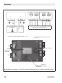
NOTICE
−−The switching voltage of the integrated solenoid valve is connected
either at the terminals V1 (81/82)
or at the terminals V3 (281/282)
(Type 3738-20-xxx1400xxx000).
−−Do not connect the switching voltage
to the contacts A-St! Otherwise, the
device will be damaged.
EB 8390 EN
Connections
V1
+
_
_
81
82
84
St
+
_
83
62
C
_
+
61
B
+
_
A
V3
+
_
282
PTO
52
51
42
41
PTC
42
41
52
51
+
281
24 V DC
24 V DC
Optionally
V1 or V3
Optionally
V1 or V3
Connection acc. to IEC 60947-5-6
Connection of integrated solenoid valve:
optionally V1 or V3
Connection of electronic limit switch:
A, B, C, St
–
+
–
+
Display
C
Rotary pushbutton
LED for solenoid valve
V1
St
+
–
–
+
B
–
+
A
–
V3
+
SAMSON
SSP interface
Fig. 12:Electrical connection – Version for internal solenoid valve (Type 3738-20-xxx1400xxx000)
EB 8390 EN
31
Connections
V2
+
_
Acc. to manufacturer´s
specifications
V1
+
81
_
_
82
84
24 V DC,
max. 18 W
Connection of external solenoid valve: V1, V2
V2
+
–
St
+
83
_
62
C
+
61
_
B
PTO 52
PTC 42
_
42
52
A
+
41
51
Connection acc. to IEC 60947-5-6
Connection of electronic limit switch:
A, B, C, St
–
+
–
+
St
C
Rotary pushbutton
Display
LED for solenoid valve
V1
+
51
41
+
–
–
+
B
–
+
A
SAMSON
SSP interface
Fig. 13:Electrical connection – Version for external solenoid valve (Type 3738-20-xxx1000xxxx00)
32 EB 8390 EN
Operator controls and readings
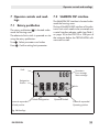
7 Operator controls and readings
7.1 Rotary pushbutton
The rotary pushbutton ( ) is located underneath the housing cover.
The electronic limit switch is operated on site
using the rotary pushbutton:
Turn
Press
: Select parameters and values
7.2 SAMSON SSP interface
The SAMSON SSP interface is located underneath the housing cover.
The local SAMSON SSP interface of the electronic limit switch needs to be connected over
a serial interface adapter cable (see Table 1
on page 18) to the RS-232 or USB port of
the computer before the TROVIS-VIEW software can be used.
: Confirm setting/exit parameter
Fault
Parameters
Error message
Status message
Designation
Position
%
Contact A responded
Fail-safe position
Unlock configuration
Units
Operation locked
Contact B responded
Operating position
Fig. 14:Readings
EB 8390 EN
33
Operator controls and readings
7.3 Operating structure
The P2 parameter allows the user to switch
between the RUN operating mode and SET
configuration mode. In the SET configuration
mode, the parameters marked with an asterisk
(*) (see section 13) can be changed and the
device can be initialized.
To switch over modes, the key code must be entered first. The key code can be found on page
77. To avoid unauthorized use of the key
code, remove the page or make the key code
unreadable.
To meet the device design requirements to conform with SIL, the SET configuration mode is indicated by the fault alarm contact St responding after the device has been initialized successfully. In the display, the SET configuration
mode is additionally indicated by the icon. If
the device has not yet been initialized or it has
been reset to its default settings (P21), the three
contacts A, B and C also respond.
It is possible to monitor the PST target range
when the P12 parameter (status readout for
PST target range) is activated. In this case, the
fault alarm contact St responds whenever the
valve position is above or below the limit ('PST
step end' ± ½ 'PST tolerance band'). This monitoring function is not active by default.
If the partial stroke test is not used, a third
switching position can be indicated by contact C.
The contacts can indicate the operating states
listed in Table 3.
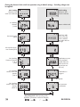
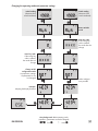
The operating structure is shown on the following pages in the form of schematic diagrams:
−− Placing the electronic limit switch into operation using its default settings (page
36)
−− Changing the operating mode and parameter settings (page 37)
After the device has been initialized and is
in RUN operating mode, various states of the
contacts can be set (see Table 3) depending on
the control and status or error messages. Parameters cannot be changed or, for example,
the device cannot be re-initialized in the RUN
operating mode for reasons of safety.
Errors E0 to E8 have priority over the switching
positions for reasons of safety. A serious device
error E9 is additionally signalized by a wire
breakage in accordance with IEC 60947-5-6.
Contact C can be used for monitoring the partial stroke test (PST). It responds when the valve
position exceeds the selected limit ('PST step
end' ± ½ 'PST tolerance band' (P14 ± ½ P15).
34 EB 8390 EN
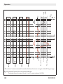
Operator controls and readings
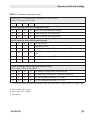
Table 3: Indication of operating states
Contacts A, B, C can configured as required (NC or NO contact)
Contact St is always a NC contact
A
B
C
St
Possible operating states in SET configuration mode
Device not initialized/default settings
Device initialized, fail-safe position
Device initialized, operating position
Possible operating states in RUN operating mode
Fail-safe position
Operating position
Fail-safe position, F0 to F10 status messages or E10 error message
Operating position, F0 to F10 status messages or E10 error message
E0 to E8 error messages, F10 status message
U
Error E9 (serious device error)
Possible operating states during partial stroke test (PST),
refer to section 9.2 for further details
PST started, PST target range not reached yet
PST target range reached/PST completed successfully
PST not completed successfully, P12 = NO
PST not completed successfully, P12 = YES
1)
The contact remains activated three seconds after the valve moves out again of the PST target range.
1)
NC = closed; NO = open
NO = open; NC = closed
U Wire break
EB 8390 EN
35
Placing the electronic limit switch into operation using its default settings – Switching voltage must
be applied!
Initial reading
(electronic limit
switch not initialized)
%
P1: Reading
direction
[1234]
Initial reading
(electronic limit
switch initialized)
Return to RUN mode
¿
Enter key code:
If the wrong key
code is entered,
the mode does not
change
P4: Actuator type
[ROT]
P5: Actuator’s direction of action [PTO]
P6: Switching
function of contacts
A, B, C
[NC]
P7: Switching
contact, lower end
position
[2.0 %]
Initialization successfully completed
%
Initialization in
progress
%
¿
P8: Switching
contact, upper end
position
[98.0 %]
36 %
Gray background: RUN operating mode
(operation, parameters cannot be changed)
¿
: Turn
: Press
Partial stroke test
(PST) can be configured (see section 9.2).
Six seconds
P9: Automatic
initialization
EB 8390 EN
Changing the operating mode and parameter settings
Initial reading
(electronic limit
switch initialized)
%
%
Initial reading
(electronic limit
switch initialized)
Return to RUN
mode
¿
¿
Enter key code:
If the wrong key
code is entered,
the mode does not
change
Enter key code:
If the wrong key
code is entered,
the mode does not
change
¿
¿
Change to SET
configuration mode
(no operation, settings
of parameters Px can
be changed)
Other configurations possible
Example:
adapting the display direction
¿
¿
EB 8390 EN
Gray background: RUN operating mode
(operation, parameters cannot be changed)
¿
: Turn
: Press
37
Start-up
WARNING!
Mount the electronic limit switch, keeping the following sequence:
−−Mount the electronic limit switch on
the actuator. Refer to section 5.2 and
5.3.
−−Connect the supply air. Refer to section 6.1 and 6.2.
−−Connect the electrical power. Refer
to section 6.3.
−−Perform the start-up settings. Refer
to section 8.
NOTICE
Perform the start-up settings in the
same sequence as described (section
8.1 to 8.7).
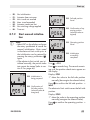
Reading after connecting the electrical power supply:
P0: Display when the
electronic limit switch
has not yet been initialized
−− The fault alarm icon and – – – – appear on the display when the electronic
limit switch has not yet been initialized.
The electronic limit switch is not in service.
Parameter settings can be changed (P2 =
SET). Refer to page 37.
Note:
The current angle of rotation is set to
0° by pressing the rotary pushbutton
( ).
−− The current angle of rotation is displayed
in % when the electronic limit switch has
been initialized. To change parameter settings, the configuration mode (SET) must
be activated. See page 37.
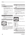
8.1 Adapting the display direction
The reading on the electronic limit switch display can be turned by 180° to adapt it to how
the electronic limit switch is mounted.
P1: Reading direction
If the displayed data appear upside down,
proceed as follows:
Turn
g P1
Press
, P1 blinks
Turn
1234/
1234
8 Start-up
Press
to confirm reading direction and to
exit the parameter.
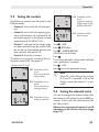
8.2 Verifying readings on display
NOTICE
For safety-instrumented systems, the
display’s functioning must be tested.
38 EB 8390 EN
Start-up
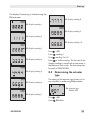
The display’s functioning is checked using the
P3 parameter.
P3: Display reading 8
P3: Display reading 1
P3: Display reading 9
%
P3: Display reading 2
P3: Display reading 10
P3: Display reading 3
Turn
Press
P3: Display reading 4
P3: Display reading 5
P3: Display reading 6
Turn
g P3
, reading 1
, reading 2 to 10
Press
to confirm testing. The last test of the
display readings is saved with a time stamp in
the electronic limit switch. The time stamp can
be read in TROVIS-VIEW.
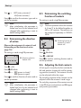
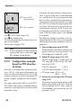
8.3 Determining the actuator
type
The setting of the actuator type (rotary or linear actuator) is made using P4 parameter.
P4: Actuator type
Default: ROT
P3: Display reading 7
EB 8390 EN
Turn
g P4
Press
, P4 blinks
39
Start-up
Turn
g
ROT (rotary actuator)/
LIN (linear actuator)
Press
to confirm the actuator type and to
exit the parameter.
Note:
After initialization, this parameter is
locked and can first be selected and
changed after performing a reset to
default settings (P21).
8.5 Determining the switching
function of contacts
The setting is made using P6 parameter.
Note:
The local operation allows the contacts
A, B and C to be defined together as
NO or NC contacts. The contacts can
be configured separately in TROVISVIEW.
8.4 Determining the direction
of action
Observe the assignment of contacts A and
B depending on the direction of action
(page 79)!
The setting is made using P5 parameter.
P5: Direction of action
Default: PTO
Turn
g P5
Press
, P5 blinks
Press
g
PTC (power to close)/
PTO (power to open)
Press
to confirm direction of action and to
exit the parameter.
40 Note:
After initialization, this parameter is
locked and can first be selected and
changed after performing a reset to
default settings (P21).
P6: Switching function of
contacts A, B and C
Default: NC
Turn
g P6
Press
, P6 blinks
Turn
g NO/NC
Press
to confirm switching function and to
exit the parameter.
8.6 Adjusting the limit contacts
A limit signal is issued by the limit switches for
fail-safe position (contact A) and for operating position (contact B). The contacts A and B
can be adjusted within the range.
The switching response of the contacts can be
adjusted within the actuator’s travel range.
The switching responses of the contacts are set
in the P7 (lower end position) and P8 (upper
end position) parameters.
EB 8390 EN
Start-up
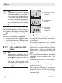
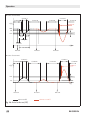
Direction of action PTC:
Direction of action PTO:
Fail-safe position 100 %
Fail-safe position 0 %
Operating position 100 % Operating position 0 %
x [%]
x [%]
100
100
Contact B
P8
Contact A
P7
Contact A
Contact B
%
P8
P7
0
0
Switching range
Fig. 15:Switching range of end positions
Note:
The following correlations apply to the
setting ranges of the switching ranges for lower end position (P7) and the
upper end position (P8):
−−P7: 0.5 % to (P8 – 2.0 %)
−−P8: (P7 + 2.0 %) to 99.5 %
Observe the assignment of contacts A and
B depending on the direction of action
(page 79)!
%
EB 8390 EN
P7: Switching contact,
lower end position
Default: 2.0 %
Example: Fail-safe
position for PTO
Turn
P8: Switching contact,
upper end position
Default: 98.0 %
Example: Operating
position for PTO
g P7/P8
Press
, P7/P8 blinks
Turn
g Required switching value
to confirm the switching value and to
Press
exit the parameter.
8.7 Initialization
WARNING!
−−The initialization must only be started when the switching voltage is
connected and the actuator is in
the operating position.
−−Check the max. permissible signal
pressure before starting initialization.
−−The actuator is moved through its
entire travel range during initialization. Therefore, do not start initialization while a process is running,
but only during start-up, when all
shut-off valves are closed.
NOTICE
After the electronic limit switch has
been mounted onto another actuator or its mounting location has been
changed and prior to re-initializing,
the electronic limit switch needs to be
reset to its default setting (Code P21).
Refer to section 8.10 on page 45).
41
Start-up
Note:
If an electronic limit switch is replaced
with another electronic limit switch of
the same type, the replaced electronic limit switch may not need to be reinitialized, provided certain conditions
are met. Refer to section 8.8 Replacing an electronic limit switch on page
44.
After the electronic limit switch has been initialized, the current valve position appears in
% on selecting P0. Keep the rotary pushbutton ( ) pressed to display the reading as an
angle (°).
Two types of initialization are available:
−− Automatic initialization with P9 parameter
−− Manual initialization with P10 parameter
by manually confirming the end positions
(POS1 and POS2)
8.7.1 Start automatic initialization
42 Note:
The automatic initialization can be
canceled by pressing the rotary pushbutton ( ). ESC appears on the display.
Data saved in the electronic limit
switch prior to the initialization can be
restored by pressing the rotary pushbutton ( ) again.
P9: Initialization is being
prepared
P9: Initialization in
progress
%
Turn
P9:Initialization
successfully
completed
g P9
Press
six seconds long. The seconds remaining until the initialization starts appear
on the display.
Initialization starts (display: INIT): The valve
moves twice from the operating position to the
fail-safe position and back again to the operating position. It measures the travel between
the end stops as well as the dead time and
transit times for opening and closing the
valve.
After the initialization has been successfully
completed, the current valve position in % is
indicated.
The electronic limit switch is in the configuration mode (SET).
To start operation, exit the configuration
mode. See page 37.
The automatic initialization is automatically
canceled if a fault occurs (ERR on the display).
The initialization error can be read in the ERR
parameter level:
EB 8390 EN
Start-up
−−
−−
−−
−−
−−
−−
−−
E0:
E1: E2: E3: E4: E5:
E6: No initialization
Actuator does not move
Min. travel not reached
Max. travel exceeded
Actuator travels too fast
No switching voltage applied
Time-out
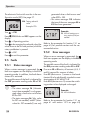
P10: Fail-safe position
found
P10: Confirmation of operating position
(solenoid valve energized)
8.7.2 Start manual initialization
Note:
−−Select ESC on the display and press
the rotary pushbutton to cancel the
manual initialization. Data saved
in the electronic limit switch prior to
the initialization can be restored by
pressing the rotary pushbutton ( )
again.
−−If the electronic limit switch was initialized manually, the partial stroke
test cannot be started (refer to section 9.2 on page 46).
P10: Initialization is
being prepared
P10: Confirmation of
fail-safe position
(solenoid valve deenergized)
P10: Operating position
found
%
Turn
P10:Initialization
successfully
completed
g P10
Press six seconds long. The seconds remaining until the position check starts appear on
the display.
Display: POS1
))Move
the valve to the fail-safe position
manually (de-energize the solenoid valve).
Press
WAIT
to confirm the fail-safe position g
The electronic limit switch saves the fail-safe
position.
Display: POS2
))Move the valve to the operating position
manually (energize the solenoid valve).
Press
WAIT
EB 8390 EN
to confirm the operating position g
43
Start-up
The electronic limit switch saves the operating position.
After the initialization has been successfully
completed, the current valve position in % is
indicated.
The electronic limit switch must be in the configuration mode (SET).
To start operation, exit the configuration
mode. See page 37.
The manual initialization is automatically canceled if a fault occurs (ERR on the display).
The initialization error can be read in the ERR
parameter level:
−−
−−
−−
−−
E0:
E2: E3: E6: No initialization
Min. travel not reached
Max. travel exceeded
Time-out
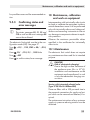
8.8 Replacing an electronic limit switch
An (old) electronic limit switch can be replaced by another (new) electronic limit switch
of the same type by performing an end position calibration in the operating or fail-safe
position, but without having to initialize the
new one, provided the following conditions
are met:
−− Data from the electronic limit switch being replaced are downloaded and saved
in TROVIS-VIEW.
−− The screw with magnet must not be unfastened while the electronic limit switch
is being replaced.
44 −− The end stops of the valve must not be
changed while the electronic limit switch
is being replaced.
Replacing an electronic limit switch
))Download and save data from the electronic limit switch being replaced in TROVIS-VIEW.
))Replace electronic limit switch.
))Load data from TROVIS-VIEW
new electronic limit switch.
onto the
))Perform an end position calibration as described in section 8.9.
8.9 Zero/end position calibration
When the zero point or end positions are incorrect, it may be necessary to recalibrate
them. Always perform an end position calibration for the fail-safe position and for the
operating position.
The electronic limit switch must be in the configuration mode (SET). See page 37.
P11: Zero/end position
calibration in progress
Turn
g P11
Press
six seconds long. The seconds remaining until the end position calibration
starts appear on the display.
The current valve position is set to the end stop
(0 % or 100 %).
EB 8390 EN
Start-up
The electronic limit switch must be in the configuration mode (SET).
To start operation, exit the configuration
mode. See page 37.
))Re-initialize the electronic limit switch (see
section 8.7).
))Set PST parameters (see section 9.2).
The end position calibration is automatically
canceled if a fault occurs (ERR on the display).
The error can be read in the ERR parameter level:
−− E6: Time-out
−− E8: Unable to calibrate end positions
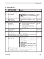
8.10Reset to default settings
This function resets all parameters to the factory default settings (see parameter list in section 13 on page 57). All error and status
messages are also reset.
NOTICE
After performing a reset, the electronic limit switch needs to be re-initialized
(see section 8.7).
The electronic limit switch must be in the configuration mode (SET). See page 37.
P21: Reset
Turn
g P21
Press
, P21 blinks
Turn
g RST
Press .
The initialization values are reset to the default settings.
EB 8390 EN
45
Operation
9 Operation
WARNING!
The actuator shaft moves while the
electronic limit switch is operating.
Do not touch the actuator shaft or obstruct it to avoid risk of injury to hands
or fingers.
9.1 Lock operation
When the locking function is active, the electronic limit switch can only be operated remotely using the TROVIS-VIEW software. The
locked local operation of the electronic limit switch is indicated on the display by the
icon.
The local operation is locked and unlocked in
the TROVIS-VIEW software.
9.2 Partial stroke test (PST)
WARNING!
Ear protection must be worn if the test
is performed on the version with integrated solenoid valve while the housing cover is open!
The probability of failure on demand (PFD)
can be reduced and maintenance intervals
can be extended by the partial stroke test
(PST).
This helps prevent the valve from seizing up in
its operating position.
−− An automatic initialization must have
been performed. Refer to section 8.7.1.
−− The switching voltage must be applied.
Test procedure (Fig. 16)
The electronic limit switch issues pulses of various lengths to the solenoid valve (briefly deenergizing it) during the partial stroke test
(PST), moving the valve further towards the
fail-safe position.
The test has been completed successfully when
the valve has reached the target range ('PST
step end' ± ½ 'PST tolerance band') by one
pulse, but not exceeded it. When the target
range is reached, contact C responds
The analysis of a successfully completed test
provides the following data:
−−
−−
−−
−−
−−
−−
−−
PST pulse length
PST dead time
PST transit time SV de-energized
PST hold time
PST transit time SV energized
PST travel
PST status
If the test could not be completed, the corresponding F8 or F9 status message is generated:
−− F8: No switching voltage during PST
−− F9: Time-out during PST
The following conditions must be met before
the partial stroke test (PST) can be performed:
46 EB 8390 EN
Operation
Note:
−−If the travel of the PST is monitored
and, if necessary, the status messages F6 ('Min. value for PST not
reached') and F7 ('Max. value for
PST exceeded') are to be generated, the P12 parameter must be set
to YES.
−−Contact C can be used to indicate a
third switching position. Refer to following example for direction of action PTO.
Contact C
x [%]
Contact B
Contact A
Contact B
100
P8
P14
P15
P7
t [s]
EB 8390 EN
47
Operation
Direction of action PTO
Contact C
Contact B
Contact C
Contact B
Contact B
Contact B
x [%]
Contact St
100
P8
P15
P14
SV off
SV on
Holding time
Dead time
t [s]
PST duration
PST start
PST start
PST start
Direction of action PTC
Contact C
Contact B
Contact C
Contact B
Contact B
Contact B
Contact St
x [%]
P14
P15
P7
t [s]
PST start
PST successful
PST start
PST start
PST not successful
Fig. 16:Partial stroke test (PST)
48 EB 8390 EN
Operation
9.2.1 Defining the PST target
range
9.2.2 Starting the partial
stroke test
Define the target range by configuring P14
and P15 parameters.
A single PST test can be started manually or a
regular PST test can be started automatically
at defined time intervals.
PST target range = 'PST step end' (P14) ± ½
'PST tolerance band' (P15)
NOTICE
It is important to take the process conditions (e.g. pressure, medium, dead
time, breakaway torque and torque of
the valve) into account on defining the
PST target range. A valve that opens
(PTC) and closes (PTO) too far may affect the process!
The electronic limit switch must be in the configuration mode (SET). See page 37.
%
Start PST automatically at defined intervals
(RUN mode)
The test is performed automatically after a
time interval (days) entered in P16 ('Automatic PST).
NOTICE
The automatic test causes the valve to
leave its operating position without a
switching demand.
P14: PST step end
Default: 90.0 %
Note:
The default setting OFF causes the automatic test to be deactivated.
P16: Start automatic PST
%
Turn
P15: PST tolerance band
Default: 10.0 %
g P14/P15
Press
, P14/P15 blinks
Turn
g PST step end/PST tolerance band
Press
to confirm the value and to exit the
parameter.
Turn
g P16
Press
, P16 blinks
Turn
g Required time period [days]
Press
to confirm the entry and to exit the
parameter.
Start PST manually (SET or RUN configuration mode)
A single test is started by the P17 parameter.
EB 8390 EN
49
Operation
P17: Start of PST is
being prepared
P17: Test in progress
Turn
g P17 (travel range in %)
six seconds long.
Press
The seconds remaining until the test starts appear on the display.
The test starts (display: PST).
Note:
A test in progress can be canceled by
pressing the rotary pushbutton ( ).
ESC appears on the display.
9.2.3 Configuration example
based on PTO direction
of action
The valve is normally open (operating position = 100 %). In the event of emergency, the
valve is to close (fail-safe position = 0 %). The
actuator's direction of action is therefore PTO
(power to open), configured in the P5 parameter.
The upper end position (P8) is set at 98 %.
This value is the same as the default setting.
Contact B is activated when the valve moves
beyond this value.
50 To prevent the valve seizing in the open position, a partial stroke test is to be performed
on a weekly basis. During the partial stroke
test, the valve is moved from the operating position towards the fail-safe position to a step
end of 90 % by briefly de-energizing the solenoid valve. During the test, the valve must not
move beyond a position of 85 % and a status message is activated for monitoring purposes if the PST target range is not reached
or exceeded.
The following settings are made to the initialized electronic limit switch in the example
while taking the process conditions into consideration:
1. Select configuration mode SET (P2)
The parameters required to configure the
partial stroke test can only be set in the
SET configuration mode (P2 = SET).
2. Define PST target range (P14, P15)
The PST target range is made up of the
'PST step end' (P14) and the 'PST tolerance band' (P15).
P14 ('PST step end')
= 90 %
P15 ('PST tolerance band') = 10 %
g PST target range= 90 % ± 5 %
= 85 % … 95 %
3. Activate the monitoring of the PST target
range (P12)
The monitoring of the target range as well
as the status readout F6 'Min. value for
PST not reached' and F7 'Max. value for
PST exceeded' are activated by the P12
parameter = YES.
EB 8390 EN
Operation
When the status message F6 or F7 is generated, check the attachment, supply air
lines and the valve. If necessary, the settings of the target range must be changed
accordingly (P14 and P15). See "Define
PST target range (P14, P15)" in point 2.
4. Start automatic PST (P16)
P16 = 7 days
The test starts automatically once a week
after switching to RUN operating mode.
The valve leaves the operating position
(100 %) without a switching demand.
5. Select RUN operating mode (P2)
The countdown starts after the electronic
limit switch has been switched to the RUN
operating mode (P2 = RUN).
6. Evaluate PST (Fig. 17)
A partial stroke test is successfully completed when the valve reaches the defined PST
target range, but has not moved beyond
it. Contact C responds when the valve enters the PST target range and remains activated three seconds after the valve leaves
the PST target range again.
The status contact St remains in the no response state (> 2.1 mA) as long as the PST
target range is reached and not exceeded.
If the status contact St is activated by the
valve not reaching the PST target range,
it remains activated until the next partial
stroke test is started. This partial stroke test
is then reevaluated.
EB 8390 EN
The evaluation of the performed test provides the following data:
−−
−−
−−
−−
−−
−−
−−
PST pulse length
PST dead time
PST transit time SV de-energized
PST hold time
PST transit time SV energized
PST travel
PST status
Check the voltage supply and solenoid
valve wiring when the status message
F8 ('No switching voltage during PST') is
generated.
Check the attachment and supply air line
when the status message F9 ('Timeout during PST') is generated.
The last 10 evaluations are saved in a
non-volatile memory in the electronic limit switch and can be read in the TROVISVIEW software.
The solenoid valve is briefly de-energized
by pulses issued by the electronic limit
switch to close the valve.
In this example, the valve does not reach the
PST target range during the first partial stroke
test and moves beyond it. The test was not successfully completed. In the second automatic
test, the valve initially does not reach the PST
target range. The next step though ends in the
PST target range, meaning the test has been
successfully completed.
51
85
P14 – ½ P15
P15 = 90
P14 + ½ P15 ⇒ 95
100
P8 = 98
x [%]
> 2.1 mA
< 1.2 mA
Contact St
> 2.1 mA
< 1.2 mA
Contact C
< 1.2 mA
Contact B
> 2.1 mA
< 1.2 mA
Contact A
> 2.1 mA
Start
PST 1
not successful
*
End
Start
PST 2
successful
*
End
t [s]
Target
range
Operation
* The contact C remains activated 3 seconds after the valve moves out again of the PST target range.
Fig. 17:Example: Course of first two partial stroke tests
The graph shows the states when A, B and C contact setting = NC (P6)
52 EB 8390 EN
Operation
9.3 Testing the contacts
P19: Simulation of contact C:
(signal on reaching
target range during
partial stroke test)
The following contacts can be tested in the
P19 parameter.
−− Contact A: Limit switch for fail-safe position
−− Contact B: Limit switch for operating position and simulation of wire break (B_LB
parameter appears on the display to meet
requirements of IEC 60947-5-6)
−− Contact C: Indicates that the target range
has been reached during the partial stroke
test or that an intermediate position has
been reached. See section 9.2.
−− Contact St: Fault alarm contact
The electronic limit switch must be in the configuration mode (SET). See page 37.
Display when P6 = NC
P19: Simulation of contact A
(limit switch for failsafe position)
P19: Simulation of contact B
(limit switch for operating position)
P19: Simulation of wire
break at contact B
P19: Simulation of fault
alarm contact
Turn
g P19
Press
, P19 blinks
g A/B/B_LB/C/St
Turn
All contacts are activated.
Press .
The contact selected is deactivated while the
rotary pushbutton is pressed.
Turn
Press
g ESC
to exit the parameter setting.
Note:
When P6 = NO, the logic for contacts
A, B and C is reversed. B_LB on the
display means the contact C is activated.
9.4 Testing the solenoid valve
You can de-energize the solenoid valve while
the voltage is still applied using the P20 parameter. In this case, the valve moves to the
fail-safe position.
Observe the assignment of contacts A and B
depending on the direction of action (page
page 79)!
EB 8390 EN
53
Operation
The electronic limit switch must be in the configuration mode (SET). See page 37.
P20: Testing solenoid
valve
%
Turn
Example: PTO
g P20
Press , P20 blinks and ESC appears on the
display.
Turn
g Operating position
to de-energize the solenoid valve (the
Turn
valve moves to the fail-safe position) while the
rotary pushbutton is pressed.
Turn
Press
g ESC
to exit the parameter.
9.5 Faults
9.5.1 Status messages
When a status message is generated, the
fault icon appears on the display in the RUN
operating mode. In addition, the fault alarm
contact St is activated.
The possible cause of the fault is indicated by
the STAT parameter reading under F0 to F10.
54 Note:
−−The status message F4 ('Actuator
transit time exceeded') is only generated when a fault occurs and when
P13 ≠ OFF.
−−The status messages F6 ('Min. value
for PST not reached') and F7 ('Max.
value for PST exceeded') are only
generated when a fault occurs and
when P12 = YES.
−−The status message F10 indicates
that one of the error messages E0 to
E10 has been generated.
Example:
F2: Limit of maximum rotary motion (P26) exceeded
Refer to the parameter list (section 13.1 on
page 61) for possible causes and the recommended action.
9.5.2 Error messages
When an error message is generated, the
fault icon appears on the display in the RUN
operating mode.
The possible cause of the fault is indicated by
the ERR parameter reading under E0 to E10.
If an error E0 to E8 exists, all contacts (A, B, C
and St) respond for reasons of safety.
Error E9 (device error 1) causes a wire break
(contact B) to be additionally signaled to meet
requirements of IEC 60947-5-6.
Error E10 (device error 2) causes the switching position to be displayed unchanged.
Example:
E0: No initialization
Refer to the parameter list (section 13.1 on
page 61 and section 13.2 on page 63)
EB 8390 EN
Maintenance, calibration and work on equipment
for possible causes and the recommended action.
10 Maintenance, calibration
and work on equipment
9.5.3 Confirming status and
error messages
Interconnection with intrinsically safe circuits
to check or calibrate the equipment inside or
outside hazardous areas is to be performed
only with intrinsically safe current/voltage calibrators and measuring instruments to rule out
any damage to components relevant to explosion protection.
Note:
The status messages F0, F1, F3 and
F10 as well as the error message E0
cannot be confirmed.
The electronic limit switch must be in the configuration mode (SET). See page 37.
Turn
ERR
g F0/…/F10, STAT or E0/…/E10,
Press
, F0/…/F10, E1/…/E10 blinks
Turn
g RST
Press
to confirm status/error message.
Observe the maximum permissible values
specified in the certificates for intrinsically
safe circuits.
10.1Maintenance
The electronic limit switch does not require
any maintenance when used for its intended
purpose.
DANGER!
Risk of electrostatic charging!
Due to the high surface resistance of
the enclosure cover (RIsol. ≥ 109 Ω),
installation and maintenance on the
equipment must be performed in such
a way that electrostatic charging cannot occur.
Version with integrated solenoid valve
(Type 3738-20-xxx1400xxx000)
There are filters with a 100 µm mesh size in
the pneumatic connections for supply and output which can be removed and cleaned, if required.
The maintenance instructions of any upstream
supply air pressure reducing stations must be
observed.
EB 8390 EN
55
Servicing explosion-protected devices
11 Servicing explosion-protected devices
12 Firmware update (serial interface)
If a part of the device on which the explosion
protection is based needs to be serviced, the
device must not be put back into operation until a qualified inspector has assessed it according to explosion protection requirements, has
issued an inspection certificate or given the
device a mark of conformity.
Firmware updates on electronic limit switches currently in operation can be performed
as follows:
Inspection by a qualified inspector is not required if the manufacturer performs a routine
test on the device prior to putting it back into
operation. Document the passing of the routine test by attaching a mark of conformity to
the device.
Replace explosion-protected components only by original, routine-tested components provided by the manufacturer.
Devices that have already been used outside
hazardous areas and are intended for future use inside hazardous areas must comply
with the safety requirements placed on serviced devices. Before being operated inside
hazardous areas, test the devices according
to the specifications for servicing explosionprotected devices.
When updates are performed by a service
employee appointed by SAMSON, the update
is confirmed on the electronic limit switch by
the test mark assigned by SAMSON’s Quality Assurance.
In all other cases, only plant operator personnel with written approval may perform updates. Updates are to be confirmed by approved personnel on the device.
Laptops and PCs connected to the power supply must not be used without an additional
protective circuit.
This does not apply to laptops in battery operation. In this case, it is assumed that a battery-powered laptop runs briefly for software
programming or testing purposes.
a) Updates outside the hazardous area:
Remove the electronic limit switch from the
plant and update it outside the hazardous area.
b) Updates on site:
Updates on site are only permitted after
the plant operator presented a signed hot
work permit.
After updating has been completed, add
the current firmware to the nameplate; this
can be done using labels.
56 EB 8390 EN
Parameter list
13 Parameter list
No.
Parameter – Readings,
values [default setting]
Description
Parameters marked with an asterisk (*) can only be changed when the electronic limit switch is in the
SET configuration mode (set in P2).
P0
Info: actual value
After initialization: current valve position in %
See secKeep
pressed down –> current valve position tion 8
in ° (angle)
Prior to initialization: Travel in °
P1
Reading direction
The reading direction of the display is turned
by 180°.
See section
8.1
RUN · [SET] · ESC
RUN: Operation mode, parameter settings
cannot be changed
See page
37
P3
Verify LCD segments
Read only
See section
8.2
P4*
Actuator type
ROT:
Rotary actuator
[ROT] · LIN · ESC
LIN:
Linear actuator
See section
8.3
1234
1234 ·
· ESC
Start-up
P2
Configuration
SET:
Configuration mode (device not in
service, parameter settings can be
changed, ,
0000 to 9999
Note: After initialization, this parameter is locked and can first be selected and
changed after performing a reset to default settings (P21).
P5*
Direction of action of actuator PTO (power to open):
Fail-safe position = Valve CLOSED, 0 % of
[PTO] · PTC · ESC
travel range
Operating position = Valve OPEN, 100 %
of travel range
See section
8.4
PTC (power to close):
Fail-safe position = Valve OPEN, 100 % of
travel range
Operating position = Valve CLOSED, 0 % of
travel range
Note: Observe the assignment of contacts A and B depending on the direction
of action (page page 79)!
After initialization, this parameter is locked and can first be selected and
changed after performing a reset to default settings (P21).
EB 8390 EN
57
Parameter list
No.
Parameter – Readings,
values [default setting]
P6
Switching function of contacts NC contact
A, B, C
NO contact
[NC] · NO
Description
See section
8.5
NX1 … NX6
ESC
Note: The contacts A, B and C can be individually configured in the TROVISVIEW software.
This indicated on the display as NX1 … NX6.
All the contacts are configured together as NC contact (1) or NO contact (2) by
the local operation.
P7*
Switching contact, lower end
position
0.5 % to (P8 – 2.0 %) · ESC
[2.0 %]
The following applies:
PTO g Switching contact for fail-safe position
See section
8.6
PTC g Switching contact for operating position
Note: Observe the assignment of contacts A and B depending on the direction
of action (page 79)!
P8*
Switching contact, upper end
position
(P7 + 2.0 %) to 99.5 % · ESC
[98.0 %]
The following applies:
PTO g Switching contact for operating position
See section
8.6
PTC g Switching contact for fail-safe position
Note: Observe the assignment of contacts A and B depending on the direction
of action (page 79)!
P9*
Automatic initialization (INIT)
Starts initialization
See section
8.7.1
P10*
Manual initialization (INIT)
Initialization after manual confirmation of failsafe position (POS1) and operating position
(POS2)
See section
8.7.2
P11*
End position calibration
A calibration at the current position is performed.
See section
8.9
Issue status message F6/F7 if the valve moves
to a position outside the PST target range ('PST
step end' ± ½ 'PST tolerance band').
See section
9.2
Status readout
P12*
Status readout PST target
range
YES · [NO] · ESC
58 EB 8390 EN
Parameter list
No.
Parameter – Readings,
values [default setting]
Description
P13*
Status readout actuator transit time
Issue status message F4 when the actuator exceeds the adjusted actuator transit time.
See section
9.5.1
[OFF] · 0.5 to 1800.0 s · ESC
Partial stroke test (PST)
The PST step range is limited between 2 and 98 % ('PST step end' ± ½ 'PST tolerance band')
P14*
PST step end
4.0 to 96.0 % · ESC
P15*
[90.0 %]
If the partial stroke test is not used, a third
switching position can be indicated by contact C.
PST tolerance band
Tolerance added to the PST step end position.
4.0 to 96.0 % · ESC
[10.0 %]
P16*
Step end position that the valve is to be moved
to during the PST.
Start automatic PST
See section
9.2
The partial stroke test has been completed successfully when the valve has reached the target
range ('PST step end' ± ½ 'PST tolerance band')
by one pulse, but not exceeded it.
Interval between automatic partial stroke tests
See section
9.2
A single automatic partial stroke test is started.
See section
9.2
HMI:
Locking of local operation (icon:
See section
9.1
SSP:
Locking of remote operation in TROVISVIEW.
[OFF] · 1 to 999 days · ESC
P17
Start manual PST
See section
9.2
Locking function
P18*
Lock operation
[NO] · SSP · HMI · ESC
)
Only using TROVIS-VIEW!
Only with local operation!
Test functions
P19*
Testing contacts A, B, B_LB,
C, St
Checking of contacts A, B, C and St
See section
9.3
ESC
Note: B_LB on the display simulates a wire break according to NAMUR at contact B.
P20*
Testing solenoid valve
EB 8390 EN
Solenoid valve de-energized (fail-safe position)
See section
9.4
59
Parameter list
No.
Parameter – Readings,
values [default setting]
Description
Reset function
P21*
Reset
RST · ESC
Resets all settings of electronic limit switch to the
factory default settings.
See section
8.10
Display functions · Read only
P22
Info: actuator transit time
Time [s] required by the actuator to move to the
when solenoid valve is de-en- fail-safe position (dead time + transit time)
ergized
Values determined during automatic initialization (P9)
–
P23
Info: actuator transit time
when solenoid valve is energized
Time [s] required by the actuator to move to the
operating position (dead time + transit time)
–
P24
Info: temperature
Current operating temperature [°C] inside the
electronic limit switch
P25
Info: operating hours
Number of operating hours
–
Status message F2 is set when the max. number
of rotary motions has been reached.
–
Values determined during automatic initialization (P9)
Keep
–
pressed down –> reading in °F
Rotary motions
P26*
Max. rotary motions
OFF · 100 to 9.9E7 · ESC
[1.0E4]
Note: The monitoring of the rotary motions is deactivated by P26 = OFF.
P27*
Reset rotary motion counter
RST · ESC
The unopened parameter indicates the number of rotary motions from one end position to
the other.
–
To reset the counter, open the parameter, select
RST and confirm.
Firmware version
P28
60 Info: firmware version
Current firmware version
–
EB 8390 EN
Parameter list
13.1Status messages
No.
Status message
Possible causes
Status messages marked with an asterisk (*) can be confirmed in SET configuration mode. See section
9.5.1.
TROVIS-VIEW: Current status messages are saved with a time stamp in [Diagnostics – Status messages].
F0
Stationary outside required/desired end
positions
• Mechanical blockage
• Supply pressure too low
• External leakage
Recommended action
• Check attachment and supply air line.
F1
Left end position without being required to
move
• Incorrect voltage supplied to the solenoid valve
• Supply pressure too low
• External leakage
Recommended action
• Check switching voltage to integrated/external solenoid
valve.
• Check supply air line.
F2
Limit of maximum rotary motion (P26) exceeded
The value entered in P26 for the maximum rotary motion has
been exceeded.
Recommended action
• Deactivate function or enter higher value.
F3
Temperature limits exceeded
The temperature in the electronic limit switch is too low/too
high.
Recommended action
• Check the operating conditions.
F4*
Actuator transit time
exceeded
The actuator transit time has exceeded the limit entered in P13.
Recommended action
• Check attachment.
• Enter a higher limit.
Note: The status message is only generated when P13 ≠ OFF.
EB 8390 EN
61
Parameter list
No.
F5*
Status message
Possible causes
Actuator stationary when required to
move
• Mechanical blockage
• Supply pressure too low
• External leakage
Recommended action
• Check attachment and supply air line.
Note: If the valve moves after a delay, F5 remains active until the next successful switching demand.
Partial stroke test (PST)
F6*
Min. value for PST not
reached
• Mechanical blockage
F7*
Max. value for PST exceeded
• Supply pressure too low
• Friction too high
Recommended action
• Check attachment and supply air line.
• Check valve.
Note: The status messages are only generated when P12 = YES.
F8*
No switching voltage
during PST
• Incorrect voltage supplied to the solenoid valve
• Breakage of wire to external solenoid valve
Recommended action
• Check switching voltage to integrated/external solenoid
valve.
Note: It is only evaluated when the partial stroke test is started manually (P17).
F9*
Time-out during PST
• Mechanical blockage
• Supply pressure too low
• External leakage
Recommended action
• Check attachment and supply air line.
Error messages
F10
62 Error E0 to E10 exists
See section 13.2.
EB 8390 EN
Parameter list
13.2Error messages
No.
Error message
Possible causes
Error messages marked with an asterisk (*) can be confirmed in SET configuration mode. See section
9.5.2.
TROVIS-VIEW: The last 32 error messages are displayed with a time stamp in [Diagnostics – Logging of device errors].
E0
Positioner not initialized
• The electronic limit switch has not yet been initialized.
Recommended action
• Start initialization with P9 or P10 parameter.
E1*
INIT: actuator does not
move
• Mechanical blockage
• Supply pressure too low
• External leakage
• Incorrect voltage supplied to the solenoid valve
Recommended action
• Check attachment and supply air line.
• Check switching voltage to integrated/external solenoid
valve.
E2*
INIT: min. travel not
reached
• Mechanical blockage
• Supply pressure too low
• External leakage
Recommended action
• Check attachment and supply air line.
• Increase angle of rotation at the actuator.
E3*
INIT: max. travel exceeded
• Maximum angle exceeds 170°.
Recommended action
• Reduce angle of rotation at the actuator.
E4*
INIT: actuator travels
too fast
• KV coefficient of solenoid valve too high
Recommended action
• Install a restriction.
• Version for external solenoid valve:
Reduce KV coefficient at solenoid valve.
EB 8390 EN
63
Parameter list
No.
E5*
Error message
Possible causes
INIT: no switching voltage applied
• Incorrect voltage supplied to the solenoid valve
• Forced venting active during initialization
Recommended action
• Check switching voltage to integrated/external solenoid
valve.
• Check forced venting input.
E6*
INIT: time-out
• Supply pressure too low
• Friction too high
• KV coefficient of solenoid valve too low
Recommended action
• Check attachment and supply air line.
• Version for external solenoid valve:
Use a different solenoid valve with a higher KV coefficient.
E7*
Function canceled
• Internal error
Recommended action
• Repeat function/initialization.
E8*
Unable to calibrate
end positions
• The end stops have shifted by 10° at the minimum.
Recommended action
• Re-initialize the electronic limit switch.
Device error
E9*
Device error 1
• Internal error
Recommended action
• Restart the electronic limit switch (return it to SAMSON if
error repeatedly occurs).
Note: When E9 is generated, the wire break (contact B_LB) is additionally signaled in
accordance with IEC 60947-5-6.
E10*
Device error 2
• Internal error
Recommended action
• The electronic limit switch should be replaced soon. The device still functions.
64 EB 8390 EN
Dimensions in mm
14 Dimensions in mm
231
84
42
20
10
17
130
185
30
40
97
EB 8390 EN
65
66 EB 8390 EN
EB 8390 EN
67
68 EB 8390 EN
EB 8390 EN
69
70 EB 8390 EN
EB 8390 EN
71
72 EB 8390 EN
EB 8390 EN
73
Index
Index
Firmware update................................... 56
A
I
Accessories........................................... 18
Actuator type........................................ 39
Article code............................................ 7
Attachment
accessories...................................... 18
to linear actuators............................ 19
to rotary actuators........................... 22
Initialization
automatic........................................ 42
manual........................................... 43
L
Limit contacts........................................ 40
M
Maintenance......................................... 55
C
O
Cable entry........................................... 30
Operating structure............................... 34
Calibration........................................... 55
Operation............................................. 46
lock................................................ 46
Communication
TROVIS-VIEW................................. 12
Connections
electric............................................ 29
pneumatic....................................... 28
Contacts
technical data.................................. 15
testing............................................. 53
D
Design.................................................... 8
Direction of action................................... 8
Display
adapt..............................................
device initialized..............................
device not yet initialized...................
verifying readings............................
Operator controls.................................. 33
P
Parameter list........................................ 57
Partial stroke testing............................... 46
R
Replacing electronic limit switch.............. 44
Reset to default settings.......................... 45
Rotary pushbutton................................. 33
S
Safety instructions................................... 6
38
38
38
38
Safety-related information...................... 12
End position calibration......................... 44
SSP interface......................................... 33
E
Error messages............................... 54, 63
F
Fault..................................................... 54
74 Servicing.............................................. 56
Solenoid valve
technical data.................................. 16
testing............................................. 53
Start-up................................................ 38
Status messages.............................. 54, 61
EB 8390 EN
Index
Supply.................................................. 28
Supply pressure..................................... 28
Switching function of contacts................. 40
T
Technical data
electronic limit switch....................... 14
solenoid valve................................. 16
Testing contacts..................................... 53
Testing solenoid valve............................ 53
W
Wire break........................................... 30
Z
Zero calibration.................................... 44
EB 8390 EN
75
76 EB 8390 EN
Key code
EB 8390 EN
42
77
Parameter list
P0
Info: actual value
P1
Reading direction
P2
P3
Status messages
F0
Stationary outside required/desired end positions
Configuration: RUN/SET
F1
Left end position without being required to move
Verify LCD segments
F2
Limit of P26 exceeded
P4*
Actuator type
F3
Temperature limits exceeded
P5*
Actuator's direction of action
F4
Actuator transit time exceeded
P6*
Switching function of contacts A, B, C
F5
Actuator stationary when required to move
P7*
Switching contact, lower end position
F6
Min. value for PST not reached
P8*
Switching contact, upper end position
F7
Max. value for PST exceeded
P9*
Automatic initialization
F8
No switching voltage during PST
P10*
Manual initialization
F9
Time-out during PST
P11*
End position calibration
F10
Error E0 to E10 exists
P12*
Status readout PST target range
P13*
Status readout of actuator transit time
E0
No initialization
P14*
PST step end
E1
INIT: actuator does not move
P15*
PST tolerance band
E2
INIT: min. travel not reached
P16*
Start automatic PST
E3
INIT: max. travel exceeded
P17*
Start manual PST
E4
INIT: actuator travels too fast
P18*
Lock operation
E5
INIT: no switching voltage applied
P19*
Testing contacts A, B, B_LB, C, St
E6
INIT: time-out
P20*
Testing solenoid valve
E7
Function canceled
P21*
Reset
E8
Unable to calibrate end positions
P22
Info: actuator transit time when solenoid valve is
de-energized
E9
Device error 1
P23
Info: actuator transit time when solenoid valve is
energized
E10
Device error 2
P24
Info: temperature
P25
Info: operating hours
P26*
Max. rotary motions
P27*
Reset rotary motion counter
P28
Info: firmware version
Error messages
The parameters/errors marked with an asterisk (*) can
only be changed/confirmed in the SET configuration
mode.
Assignment based on the direction of action
Assignment based on the direction of action
PTO (power to open)
Contact A
Contact B
+
–
Position
Switching contact for end position
41
42
Fail-safe position (0 %) · Valve CLOSED
P7 (0.5 to 96.0 %, [2.0 %])
51
52
Operating position (100 %) · Valve
OPEN
P8 (4.0 to 99.5 %, [98.0 %])
PTC (power to close)
Contact A
Contact B
+
–
Position
Switching contact for end position
51
52
Fail-safe position (100 %) · Valve OPEN
P8 (4.0 to 99.5 %, [98.0 %])
41
42
Operating position (0 %) · Valve
CLOSED
P7 (0.5 to 96.0 %, [2.0 %])
EB 8390 EN
79
Weismüllerstraße 3 · 60314 Frankfurt am Main, Germany
Phone: +49 69 4009-0 · Fax: +49 69 4009-1507
Internet: http://www.samson.de
EB 8390 EN
2014-04-08
SAMSON AG · MESS- UND REGELTECHNIK