1
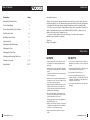
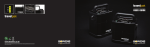
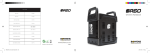
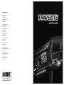
Retail Locations
New York, NY 10011
16 W. 19th St.
212-989-8500
Cambridge, MA 02141
65 Bent St.
617-576-2600
Philadelphia, PA 19147
1400 S. Columbus Blvd.
215-399-2155
Bensenville, IL 60106
890 Supreme Dr.
630-860-7458
Chicago, IL 60622
1111 N. Cherry Ave.
312-440-4920
San Francisco, CA 94110
2001 Bryant St.
415-643-9275
Santa Barbara, CA 93101
228 E. Cota St.
805-965-7053
Santa Ana, CA 92705
1430 S. Village Way, Suite A
714-285-0143
San Diego, CA 92025
830 W. Valley Parkway
760-737-6002
Los Angeles, CA 90038
1135 N. Highland
323-466-1238
1-800-CALUMET (225-8638)
www.calumetphoto.com
USER GUIDE
Table of Contents
Description
Introduction
Page
Introduction & Safety Notes
3
Control Panel Guide
4
Connecting and Using Your Travelite
5
Flash Power Control
6
Modeling Lamp Controls
6
Synchronization
6
Changing the Modeling Lamp
7
Changing the Fuse
7
Changing the Flash Tube
7
Mounting and Removing Reflectors
7
Travelite Accessories
Specifications
8–9
10 – 11
Dear Valued Customer,
Thank you for choosing the Calumet Travelite professional flash system. Accurate, ergonomic,
powerful and simple to use, the Travelite was designed by working closely with photographers
to develop a flash that meets the high standards demanded in professional studios today.
All ‘S-Type’ accessories from the Calumet/Bowens range can be used with the Travelite. For
details of all related products, please call 1-800-CALUMET (225-8638), contact your local
Calumet retail center or visit calumetphoto.com.
In order to obtain the full benefit from your purchase, please take a few moments to
familiarize yourself with this user manual.
Thank you,
Calumet Photographic
Safety Notes
ALWAYS
DO NOT’S
• Always switch power off and disconnect from
the supply before changing modelling bulb or
flash tube.
• Do not use in an environment where moisture or
flammable vapor is likely to come in contact with
the unit.
• Always disconnect the supply before changing
the fuse. Never replace with a fuse of a different
rating.
A spare fuse is fitted in the fuse holder under the
AC inlet (see page 4).
• Do not plug your Travelite into an AC supply and
a Travel-Pak battery at the same time.
• Always excercise care when handling equipment
that has been in use. The reflector and front end
of the unit can become Very Hot.
• Always avoid placing cables where they can be
tripped over. Protect from heavy, sharp or hot
objects, which may cause damage and replace
damaged cables immediately.
• Do not restrict air vents while in use.
• Do not use a unit with damaged housing,
moldings, flash tube or modeling lamp. If the unit
is dropped or damaged in any way, always have
it checked out before using.
• Do not operate the unit without a safe grounded
AC supply.
• Due to the high voltage / high energy used in
Travelites, all servicing must be carried out by a
Calumet-authorized service center.
• Always remove the power cord by gripping the
plug. NEVER pull the cord.
• Always ensure that any extension cord used has
a suitable current rating to prevent overheating
and never use coiled extension cords.
• Always remove the flash head covers before
using.
2 calumetphoto.com
calumetphoto.com 3
Control Panel Guide
Connecting and Using Your Travelite
Rear Control Panel
Operating Your Travelite
Carry handle
The Calumet Travelite may be operated either on an AC supply
or with a Calumet Travel-Pak
For AC operation, the AC switch (page 4) should be in the upper position I.
For battery operation the switch should be in the lower position II.
AC / Battery
Power Select
Photocell On/Off
The center position is off.
NOTE: When operated from a battery source, the modeling functions are not available.
• Ensure the power source is off.
Model Lamp
Full/Proportional
• Connect the unit using the appropriate cable.
AC Inlet
Modeling Lamp
Control Switch
Fuse
(and Spare Fuse)
• If using the Travel-Pak, ensure the connector locks are fully tightened.
• Switch the power source on, then switch on the Travelite.
• The unit will charge and indicate it is ready for use by illuminating the green flash-ready light.
• Press the test button to check the unit fires.
Sync Socket
Battery Power Inlet
WARNING HIGH VOLTAGE! NEVER CONNECT THE TRAVELITE TO
Side Control Panel
Photocell
BOTH AC SUPPLY AND BATTERY SUPPLY AT THE SAME TIME. THIS
APPLIANCE MUST BE GROUNDED WHEN USED WITH AC. DISCONNECT
THE AC PLUG WHEN CHANGING MODELING LAMPS AND FLASH TUBES.
Mounting Your Travelite
Reflector
Release
Mount your Travelite
on a dependable
support system
The mount bushing on the
L-bracket allows for two
possible ways of mounting
to the stand/support (RIGHT).
Flash Power/
Model Lamp Control
4 calumetphoto.com
Flash-Ready
Indicator
Test/
Open Flash
Method B may be found
useful if the light is required
to point down.
A
B
calumetphoto.com 5
Flash Power Control
The flash-power output level is variable over 5-stops, from full to 1/32 power. The maximum power
available depends upon the model (See specification table) and is denoted by the number 6 on the control
panel. The power settings are denoted in 1⁄3-stops. The numeric divisions indicate full-stop divisions.
When switched on from either AC or battery supply, the unit will charge. Once the unit has charged to the
desired power level, the green flash-ready lamp will illuminate indicating that the unit is ready to fire.
Changing the Modeling Lamp
Switch off Travelite and disconnect from the power supply. Screw modeling lamp into ES lampholder in the
center of the reflector. Allow lamp to cool before removing.
NOTE: It is recommended that a Photoflood or Halostar bulb with a maximum wattage of 275 watts
is used. The manufacturer will not accept liability on the use of any lamp with a greater wattage
than 275.
NOTE: If the unit is subjected to rapid operation over extended periods, it may automatically go
into an overheat condition. In this condition, the flash-ready lamp will illuminate to indicate the
presence of power, while the charging and modeling functions are disabled in order to allow the
unit to cool. The unit will automatically resume operation once cooled sufficiently.
In an overheat condition, the unit will typically take 15 minutes to cool down. By switching the unit off
and then on again after approximately 5 minutes, the unit can be re-activated in order to get a few extra
shots if needed.
Changing the Fuse
The modeling and flash circuitry is protected by a single 10-amp fuse mounted on the rear panel. Never
replace the fuse with one of a different rating. As the fuse may blow when the modeling lamp fails, always
check the fuse when replacing the bulb. A spare fuse is supplied in the fuse holder. Always switch the unit
and disconnect the Travelite unit from the power supply before changing the bulb or fuse.
Changing the Flash Tube
Modeling Lamp Controls
With the modeling lamp control switch (see Rear Control Panel, page 4) in the upper position the modeling
light is off. With the switch set to center, the modeling light stays on all the time. With the switch set in the
lower position, the lamp will go out when the unit is flashed and come back on when the unit comes to
ready. This enables the photographer to see from the camera position that all Travelite units in use have
fired. The modeling light may set to full power or ratioed to the flash tube setting by using the
Full/Proportional switch on the rear control panel. With the switch in the upper position, the lamp is
proportional to flash output, while in the lower position, the lamps stay at full output regardless of power
setting selected.
Ensure that the unit is switched off and disconnected from the AC
supply and then wait thirty minutes before touching/removing flash
tube. Remove the protective cap and unwind the twisted trigger
wire from the flash tube support. Gently pull the flash tube
assembly out of the unit. To replace the assembly, hold the flash
tube as shown and taking care to support both legs of the tube,
gently but firmly, push the flash tube into position, and wind the
trigger wire around the flash tube support.
Always replace with the correct flash tube assembly:
UV-Coated BW1498 Clear BW1499
Synchronization
There are several ways to trigger your Travelite
Open Flash:
For testing or multiple-flash applications the open-flash button can be used.
Sync Socket:
The standard 1⁄4" socket on the rear panel of the unit may be used for direct connection to a camera set to
'X' synchronization. Two Travelites may be connected together using a 'Y' connector. An Infrared receiver
or flash slave may also be plugged into this socket. The socket operates at +5V and is safe for use on
digital cameras.
Built-in Photocell:
The Travelite has a built-in switchable photocell enabling the unit to be triggered by the flash from any
other flash unit or a small camera mounted flash gun. It is mounted behind the red transparent cover on
the top of the unit. The photocell on/off switch is located on the rear control panel.
Mounting and Removing Reflectors
A range of reflectors is available for your Travelite. To mount, slide the neck of the reflector over the
front of the unit. Align the three pegs on the reflector with the three slots in the retaining ring. Press
down and turn clockwise to lock.
To remove reflector, pull back reflector-release (page 4), turn the reflector fully anti-clockwise and
withdraw.
If an umbrella is to be used, a 6" Umbrella reflector should be mounted and the umbrella fitted
through the hole in the mounting bracket on the reflector and locked in position with the knurled
screw.
NOTE: Take care when mounting and removing reflectors not to damage the flash-tube assembly.
The flash tube is very delicate, avoid unnecessary handling of the glass tube. Always switch the
unit off and disconnect from power supply before fitting and changing reflectors.
WARNING HIGH VOLTAGE! DO NOT TOUCH THE FLASH TUBE ASSEMBLY FOR 30
MINUTES AFTER DISCONNECTING FROM SUPPLY.
6 calumetphoto.com
calumetphoto.com 7
Accessories
Accessories
LiteLink Radio Trigger System
Reflectors
Calumet’s light-control reflectors are built to withstand many years of rigorous, daily use. They feature
extremely strong housing and steel bayonet-type mounts for quick, positive mounting. The inner steel
ring provides additional durability for frequent reflector changes. From studio sets to location sites,
Calumet’s comprehensive system of accessories can handle any situation or assignment.
LiteLink Radio Trigger System
With the Travelite you are free from AC power cables.
With the Calumet LiteLink Radio Trigger system you can
free yourself from sync cables too!
This multifunctional device can be used to trigger flash
units, film and digital cameras and light meters up to 300'
away. Because LiteLink is a radio transmittor, rather than
IR, it allows for triggering around corners or through walls
and is not affected by high ambient- light situations.
Choose from four individual channels, each providing a
unique ID for different flash devices or combine them to
trigger all equipment within a given setup or studio.
Visit calumetphoto.com
for the widest range of
photographic lighting
accessories
Because of its low-voltage operation, it is perfect for
digital cameras. Each unit can be used as either a
transmitter or receiver and operates off of two AAA
batteries. LiteLink (Set of 2) CE1560
The Travel-Pak
6" Umbrella Reflector (120°)
CE1885
7" Grid Reflector
CE18630
The Travel-Pak
The Travelite is great in the studio, but
what if you need to work on location?
Thanks to this handy battery pack, your
Calumet Travelite can leave the studio to
go on location anytime, anywhere!
Able to power two Travelites
simultaneously with a total power of up to
1500w/s, the Travel-Pak is capable of
bringing a 375w/s unit to full charge as fast
as 4 seconds, and can offer in excess of
200 flashes on a single charge.
Also available for the
Calumet Travel-Pak:
Travel-Pak Booster Battery CE1109
Travel-Pak-to-Travelite Spare Cable CE1111
Universal 2-Amp SLA Charger CE1108
8 calumetphoto.com
91 ⁄2" Reflector (50°)
CE1886
High Performance
Reflector
BW1878
Back-Lite Reflector
CE2560
With a fast/slow charge option to prolong
battery life as well as a carry bag offering
protection from the elements and up to 3"
of water, no location photographer should
be without this unique power pack.
Dimensions: 7.1(l) x 4.75(w) x 6.9(h)"
Weight: 9 lbs.
Travel-Pak CE1107
8" Reflector (60°)
CE1887
15" Soft-Lite
Reflector
CE1899
17" Sunlite
Reflector (40°)
CE1868
calumetphoto.com 9
Specifications
Travelite Specifications Comparison Chart
Unit
Travelite 375
Travelite 750
375w/s
750w/s
5V
5V
Flash Color Temperature
5600 K ±300 K
5600 K ±300 K
Circuit Protection
115V - 10A (T)
115V - 10A (T)
95-130V AC 60Hz
95-130V AC 60 Hz
±1%
±1%
Maximum Stored Energy
Sync Voltage
Supply Voltage
Voltage Stabilization
Guide Number
(Full Power, 50° Keylite, ISO 100)
Typical Recycle Time (Full Power)
220
350
1.7 sec.
2.1 sec.
Full / Intermittant / Off
Full / Intermittant / Off
1/900
1/600
Full to 1/32 (5 stops)
Full to 1/32 (5 stops)
Max 275w
Max 275w
100%
100%
Clear = BW1499 UV = BW1498
Clear = BW1499 UV = BW1498
Photocell
On/Off
On/Off
Audio-Ready Signal
On/Off
On/Off
275w Photoflood 250w Halostar
275w Photoflood 250w Halostar
6.4 lbs.
7.5 lbs.
15.13 x 6.75 x 5"
15.13 x 6.75 x 5"
Modeling Power Control
Flash Duration (t=0.5, Full Power)
Flash Power Control
Modeling Lamp
Flash-Ready Indication
User Replaceable Flash Tube
Recommended Modeling Lamps
Weight
Dimensions (l x w x h)
Due to our policy of constant product improvement, Calumet Photographic reserves the right to change equipment
specifications at any time and without notice.
10 calumetphoto.com
calumetphoto.com 11