1
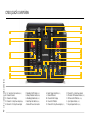
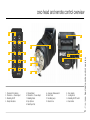
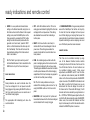
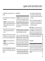
Owner’s Handbook
contents
warranty
Information
Warranty
2
Introduction
3
Safety Notes
3
Operation
Creo Pack Overview
4
Creo Head and Remote Overview
5
Connecting & Using Flash Heads 6
Modelling Options & Synchronisation 7
Ready Indication & IR Remote Control 8
Speed Control & Test Function
9
Flash Before Ready, Fan Cooling and
Protection System and Faults
10
Technical Specifications
11
All Bowens electrical products are covered by a two
year warranty against any faulty design, materials
and workmanship.
If a product does not work on arrival or up to a
maximum period of four weeks from the date of
purchase, it should be returned to the dealer/retail
outlet from where it was purchased, to exchange (if
available) the faulty unit for a new one; if the faulty
unit was part of a kit that was purchased, the dealer/
retailer may choose to simply replace the unit and
not the entire kit. Alternatively the dealer may offer
to repair the unit as soon as possible at no charge.
If neither an exchange or repair is possible for the
faulty unit, then a full refund may be made.
If a warranty fault occurs after the initial four week
period (and within the max two year warranty
period), then the unit should be returned to the
dealer, who will arrange to repair the unit as soon as
possible, at no charge.
This warranty does not apply to consumable items
such as flash tubes, modelling lamps, fuses and
consumable type batteries.
Should a unit be returned at any time within the
two year warranty period, and it is judged to have
experienced any of the following points, failure to
follow working instructions correctly, accidental or
willful damage, misuse, alteration or repair by a non
authorised Bowens service/repair centre, then a
warranty will be deemed invalid and any repairs that
may need carrying out will be payable by the owner.
The cost of repairs should be notified to the owner,
by the dealer, in advance of undertaking any work
that may be required.
No warranty repairs can be undertaken to any units
without proof of purchase.
All warranty repairs must be conducted with the
dealer from where the product was purchased.
Other terms and conditions may be applicable in
specific countries, if stated by the dealer at the time
of purchase.
All Bowens products are certified by
the CE mark. The CE certified mark
is a declaration of conformity to the
required EMC directives 2004/108/
EC ‘Electromagnetic Compatibility’
and 2006/95/EC ‘Low Voltage
Directive’.
introduction
Accurate, ergonomic and robust, the Creo
generator and Creo flash head have been designed
by working closely with photographers to develop
a system that meets the exacting high standards
demanded in professional studios while remaining
simple and intuitive to use.
For more information about these products and to
find details of your nearest Bowens dealer, please
visit the Bowens website - www.bowens.co.uk
In order to obtain the full benefit from your purchase,
please take a few moments to familiarise yourself
with this user manual.
safety notes
never
• Switch turn power OFF before before fitting or
• Always remove the power cord by gripping the
• Use in an environment where moisture or
removing any flash heads.
plug. NEVER pull the cord.
flammable vapour is likely to come into contact
• Avoid placing cables where they can be tripped
• Always ensure that any extension cord used has
with the unit.
over. Protect from heavy, sharp or hot objects,
a suitable current rating to prevent overheating
• Use a unit with damaged housing or mouldings.
which may cause damage and replace damaged
and never use a coiled extension cord.
If the unit is dropped or damaged in any way
cables immediately.
• Have the unit serviced / repaired by an authorised
Bowens service centre.
always have it checked before using.
3 - Creo | introduction and safety notes
always
creo pack overview
J
A
K
B
L
C
M
D
E
O
P
N
4 - Creo | creo pack overview
Q
F
G
R
H
S
I
T
A. 1/4” Jack Sync Connections (PG 7)
B. Channel A Socket
C. Channel A LED Display
D. Channel A 1-Stop Power Adjust (PG 6)
E. Channel A 1/10-Stop Power Adjust
F. Modelling On/Off Button (PG 7)
G. Ready Indication Button (PG 8)
H. Modelling Mode Button (PG 7)
I. Flash/Open Test Button (PG 9)
J. Mains AC Power Connection
K. Radio Trigger Card Slot (PG 7)
L. Channel B Socket
M. Channel B LED Display
N. Power On/Off Button
O. Channel B 1-Stop Power Adjust (PG 7)
P. Channel B 1/10-Stop Power Adjust
Q. Photocell / IR Receiver Window (PG 7)
R. IR Remote On/Off Button (PG 6)
S. Sync Options Button (PG 7)
T. Recycle Speed Button (PG 9)
creo head and remote control overview
1
E
2
6
A
7
4
8
F
G
B
H
C
5
9
D
1.
2.
3.
4.
Channel LED Indicators
Channel A +/- Power Adjust
Modelling On/Off
Ready Indications
5.
6.
7.
8.
9.
Channel Select
Channel B +/- Power Adjust
Modelling Mode
Sync Options
Flash/Open Test
A.
B.
C.
D.
Accessory Release Latch
Flash Tube
Modelling Lamp
Glass Dome
E.
F.
G.
H.
Carry Handle
Locking Knob
Modelling On/Off Switch
Fuse Holder
5 - Creo | creo head and remote control overview
3
connecting and using flash heads
One or two compatible flash heads may be
connected to a Creo generator. Always switch the
generator to ‘standby’ when fitting or removing any
flash heads. When connecting a flash head to a
Creo pack always ensure that the head connectors
are fully engaged with the locking clips before
turning the generator ‘on’.
6 - Creo | connecting and using flash heads
When a flash head is not fully connected/fitted, the
associated channel LED display will show ‘- -’.
When a flash head is connected fully the appropriate
channel LED display shows the selected flash
power setting in f-stops.
flash power control
The flash power adjust buttons are used to control
the power output for the associated flash head
fitted to a particular channel. A single press of either
1-Stop or 1/10-Stop flash power adjust button will
adjust the output by a single increment; the flash
power adjustment will be confirmed by a single
short beep (if the sounder is enabled).
By pressing and holding a flash power adjust
button, the generator will adjust the flash power at
an increased rate; every increment adjustment will
be confirmed by a single short beep (if the sounder
is enabled). At the end of the achievable power
range the generator will emit a long continuous
beep until the flash power adjust button is released.
The generator will not alter the actual power level
setting until a short period after the user has
stopped changing the setting; this is to avoid
unnecessary dumping/charging of the flash power.
To manually dump an excess flash power press the
‘flash/open test button’.
• The STOPS +/- buttons will adjust the flash
power by 1-Stop steps until the end of the
achievable flash power range is reached.
• The TENTHS +/- buttons will adjust the flash
power by 1/10-Stop steps until the end of the
achievable range is reached.
The maximum flash power available from each
head is dependant on the number of channels used
and the flash power setting of each channel (see
tables opposite for max power settings).
When two heads are fitted and more power is
required from a particular channel than is currently
available, then the setting of the other head must
be decreased i.e. when using a Creo 2400Ws, if
channel A is set to 9.7 then the range of channel
B is 1.0 to 6.5. By lowering the setting of channel
A to 9.4 then the power range of channel B will be
extended from 1.0 to 8.2.
Creo 1200
Channel A Max
Channel B Max
10.0
Head Not Fitted
9.7
6.5
9.4
8.2
9.0
9.0
Creo 2400
Channel A Max
Channel B Max
10.0
Head Not Fitted
9.8
5.5
9.7
7.2
9.5
8.0
9.4
8.4
9.2
8.7
9.0
9.0
modelling options and synchronisation
The MODEL button on the Creo control panel
switches the modelling lamp on and off for any
connected flash heads. The associated LED
indicator will illuminate when turned ‘on’. If the
modelling lamps are switched ‘on’ the user can
then select a modelling mode. A single press of
the MODE button will scroll through the various
modelling mode options; the associated LED
indicator will illuminate to highlight which mode is
selected. When the modelling lamps are switched
‘off’ the various ‘modelling modes’ cannot be
selected or changed and the LED indicators will
remain ‘off’. Any previous modelling mode settings
will be remembered and reverted to when the
modelling lamps are switched back ‘on’.
NB. Modelling will only work if the modelling switch
on the Creo flash head is turned ‘on’.
• PROP - automatically adjusts the modelling
output proportionally to the flash power setting.
• AUTO - automatically sets the modelling lamp
on the channel with the highest power setting to
max. When in AUTO mode, the modelling output
on the channel with the lowest flash power
setting will be set proportionally to the flash
power output on the channel with the highest
setting. If both channels are set to the same flash
power setting then the modelling output on both
channels will be set to max.
• MAX - sets the modelling on both channels to
max regardless of flash power settings.
• FREE - when FREE mode is first selected the
LED indicator will flash and the modelling
intensity on each channel will be displayed on
the appropriate channel LED displays. The
modelling output setting for each channel
can then be adjusted independently by using
the STOPS and TENTHS buttons regardless
of the flash power setting. Reducing the intensity
below ‘1.0’ will turn the modelling lamp ‘off’
and will be indicated on the appropriate channel
LED display by showing ‘- -’. The first press of
a ‘+’ STOPS or TENTHS button on the associated
channel will turn the lamp on at the lowest power
setting. When the modelling output has been
selected on each channel press the MODE
button and the chosen modelling outputs on the
appropriate channels will be set; the LED
indicator will then stay lit continuously and the
channel LED displays will revert back to
showing the flash power levels.
sync options
The Creo generator can be sync’d with a camera in
a number of ways. Each press of the SYNC button
will scroll through the various available options
and the appropriate LED indicator will highlight the
selected option.
• OFF - both LED indicators will be switched ‘off’.
In this mode the Creo generator will only trigger
from a camera or flash meter connected using a
sync cord to either 1/4” jack sync sockets (see
pack overview on page 4).
• CELL - in this mode the Creo will sync via the
‘Photocell / IR Receiver window’. The Creo will
trigger when either an IR signal is received or
when the photocell detects a flash from another
unit.
• RADIO - when this option is first selected the
appropriate LED indicator will flash for ten
seconds. During this ten second window the
Creo enters ‘learn mode’. While in ‘learn mode’
the user can sync a Pulsar transmitter with a
Pulsar radio receiver card by pressing the
TEST button on the Pulsar transmitter at least
five times (or until Creo flashes).
7 - Creo | modelling options and synchronisation
modelling mode options
8 - Creo | ready indications and ir remote control
ready indications and remote control
• RADIO - to use a particular channel/studio
setting on the Pulsar transmitter, simply turn on
the Pulsar unit and set the Pulsar to the required
setting; next, select the RADIO option on the
Creo generator by pressing the SYNC button,
during the initial ten second period while the
generator is in ‘learn mode’, press the TEST
button on the Pulsar at least five times (or until
the Creo flashes). The Creo will then learn the
channel/studio settings of the Pulsar and set
itself in accordance.
• OFF - both LED indicators will be ‘off’ and no
ready signal will utilised to highlight the Creo has
recharged to the set power level. This setting
also disables the sounder from indicating a
button press.
NB. The ‘Radio’ sync option will only work if
a Pulsar Radio Receiver Card is inserted into the
RADIO slot on top of the Creo control panel.
• DIM - the modelling lamps will dim while the
pack is recharging and will come back on when
the Creo had recharged to the set power level.
This setting also disables the sounder to indicate
a button press. Because of the fast recharging
capabilities of the Creo, the lamps may appear to
not dim with low flash power settings.
ready indications
Ready indicators are used to indicate when the
Creo has recharged to the set power level after
being triggered. By pressing the READY button on
the Creo control panel the user can select one of
four different ready signals.
The appropriate LED indicator(s) will show the
current selection:
• BEEP - the Creo will emit a clear ‘beep’ to
indicate that the unit has recharged to the set
power level. This setting also enables the
sounder to indicate that a control button has
been pressed.
NB. The ‘dim’ ready indication will only be
enabled if the modelling option is turned ‘on’ by
using the MODEL button on the Creo control
panel.
• BEEP/DIM - both ‘beep’ and ‘dim’ options will
be enabled to show when the Creo has recharged
and to indicate that it is ready to trigger.
• GREEN READY RING - the green ready indicator
around the Flash/Open Test button will stay fully
lit when the Creo has recharged to the set power
level. While charging or dumping flash power the
green indicator ring will rotate clockwise. Automatic
capacitor switching is used so dumping can occur
even if the flash power has been increased.
remote control
The Creo can be controlled remotely by using
one of the Bowens Infra-Red remote controls
including the Gemini IR Remote Control and the
Creo IR Remote Control. All main functions can
be controlled remotely except 1-Stop power
adjustments and REMOTE on/off. To set the Creo
to a particular radio channel press the REMOTE
button on the Creo control panel when the REMOTE
option is turned off, the REMOTE LED indicator will
then flash to confirm the IR channel can now be
altered and the Creo will display the current set
IR channel on the ‘Channel B LED Display’; the IR
channel can then be selected by using channel A or
B +/- STOPS or TENTHS power adjust buttons. To
confirm the IR channel selection press the REMOTE
button once; the remote LED indicator will then
stay lit continuously to confirm the selection and to
indicate the REMOTE option is turned on.
speed control and test function
speed control
• OFF - the IR receiver is ‘off’ and remote control is
not possible.
• FLASHING - the current IR channel setting is
displayed on channel B’s LED display and can be
altered using either channel A or B +/- power
adjust buttons.
The SPEED button on the Creo control panel makes
it possible to utilise the available mains power
supply by adjusting and optimising the maximum
possible speed and load without blowing fuses or
trip switches. The Creo’s amperage load from the
mains power supply corresponds proportionally to
the speed setting.
• ON - the IR receiver is ‘on’ and the Creo can be
controlled using one of Bowens IR remote
controls.
The SPEED control button is used to select one of
four recycling speed settings. The appropriate LED
indicator will highlight the chosen setting:
Depending on the set IR channel on the Creo and
the IR channel set on one of Bowens IR remote
controls, the Creo will accept IR signals as follows:
• 25% - the slowest recycling speed (25%) is
approximately four times as long as the fastest
(100%) recycling speed. This option should be
selected when the Creo is connected to a mains
power supply with weak fuses or inadequate sized
wiring, or if you are uncertain as to how well the
mains power supply is fused. It may also allow three
or four generators to be connected to the same wall
outlet or fuse group provided it is adequately fused.
• CHANNEL 0 - ANY incoming channel from
0 (ALL) - 8.
• CHANNEL 1-8 - only a matching IR channel
from 1-8 or 0 (ALL).
NB. If the Creo trigger option is set to CELL
then using an IR remote control too close to the
generator (<1m) it may cause the generator to be
triggered.
• 50% - this option is twice as long as the fastest
100%) recycling speed. This setting will allow
two generators to be attached to the same wall
outlet / fuse group (provided adequately fused).
• 75% - this option is only slightly longer than
the fastest (100%) recycling speed. It reduces
the load by 25% and may prevent sensitive fuses
from blowing.
• 100% - this is the fastest recycling speed. Only
one generator should be connected to any one
power outlet or fuse group and this should be
adequately rated and fused.
DUTY CYCLE - for the longest service life it is
recommended that the user always selects the
slowest SPEED that is consistent with the users
requirements. The Creo is designed to be able to
flash up to 1000 times at 100% (full power) per hour.
It is not recommended to run harder than necessary
due to the effect on the life of the flash tube(s).
test function
9 - Creo | speed control and test function
The REMOTE LED indicator displays the current
status as:
The Flash/Open Test Button is used to test all light
settings are correct and that the functionality is
as expected. When the Flash/Open Test Button is
pressed, any connected heads will flash and the
‘green ready indicator ring’ will rotate to indicate
charging.
flash before ready, fan cooling and protection system and faults
10 - Creo | flash before ready, fan cooling, protection system and faults
flash before ready
The ‘flash before ready’ feature makes it possible
to trigger the Creo before recharging has been
completed. If a flash is released before the
generator has recharged to the set power level a
‘warbling beep’ will be emitted and the channel
LED displays will flash for a short period. This is to
indicate a possible under-exposed frame since the
flash power may not correspond to the set power
level.
fan cooling and protection system
The Creo is equipped with an effective cooling
and protection system that operates to prevent
excessive heat build-up and possible damage.
The system comes into operation when working
at elevated temperatures, at higher flash power
settings and at faster flash rates. Limiting any of
these factors will help keep the internal temperature
of the Creo down.
• FANS - multiple fans are automatically switched
to increase the airflow through the Creo. Always
keep the vents clear of obstructions and away
from external sources of heat.
• CHARGE LIMITER - if the Creo detects a
risk of overheating by use in abnormal operating
conditions, fan failure etc. then the system
will protect the Creo by automatically reducing
the charge rate. The appropriate SPEED LED will
flash to indicate this is in operation. The Creo can
still be used in this mode but it is recommended
that the reason for the increased temperature is
found and removed.
• OVERHEAT - if the charge limiter fails to prevent
the temperature rising then the recharging will
stop completely. This will be indicated by ‘OH’
on both ‘channel LED displays’. The generator
cannot be used in this state; once the temperature has decreased sufficiently then
recharging will continue automatically. The
automatic protection should normally only
operate under extreme or fault conditions or
when the air vents are blocked. If an overheat
condition occurs it is recommended the Creo is
left switched ‘on’ without triggering it to allow the
fans to reduce the temperature accordingly.
fault indications
If a fault develops the Creo will show an error code;
this will override the ‘channel LED display’. Error
codes will be displayed as follows:
Channel A Display
Channel B Display
Meaning
E1
01
Inter-board
communication failure
E1
02
Incorrect capacitor
block configuration
E2
01
Low mains input
E2
02
Low DC link voltage
E2
03
Low mains input and
low DC links voltage
E2
08
Discharge fault
01-63
Thermal sensor fault number indicates fault
sensor
E3
If an error code is displayed it does not necessarily
mean that the unit is faulty but rather a particular
parameter is out of limits. The error may correct
itself once the cause has been removed or if the
Creo is switched to ‘standby’ and back ‘on’. If a
fault persists then the generator should be sent to a
Bowens authorised service centre for analysis.
technical specifications
Creo 1200
Creo 2400
Rated Energy (F10)
1200Ws
Rated Energy (F10)
2400Ws
Input Power Supply
100-127V / 200-240V 50/60Hz
Input Power Supply
100-127V / 200-240V 50/60Hz
Automatic Multi-Voltage
Yes (use appropriately rated modelling lamp)
Automatic Multi-Voltage
Yes (use appropriately rated modelling lamp)
Fuse
Slow Blow Fuse 16A @ 230V / 20A @ 117V
Fuse
Slow Blow Fuse 16A @ 230V / 20A @ 117V
Auto Fuse / Breaker Per Generator
Type C,D,E 16A / 230V, 20A / 117V
Auto Fuse / Breaker Per Generator
Type C,D,E 16A / 230V, 20A / 117V
Digital Energy Display
Yes (in digital F-Stops)
Digital Energy Display
Yes (in digital F-Stops)
Max Number of Heads
2
Max Number of Heads
2
Total Energy Control Range
F2.0 - F10.0
Total Energy Control Range
F1.0 - F10.0
Energy Control Increments
1-Stop and 1/10-Stop Adjustments
Energy Control Increments
1-Stop and 1/10-Stop Adjustments
Energy Distribution
Channel A=F2.0-F10.0 / Channel B=F2.0-F9.0
Energy Distribution
Channel A=F1.0-F10.0 / Channel B=F1.0-F9.0
Auto Power Dumping
Yes
Auto Power Dumping
Yes
Manual Power Dumping
Yes
Manual Power Dumping
Yes
Speed Control
100%, 75%, 50% and 25%
Speed Control
100%, 75%, 50% and 25%
Ready Indications
Beep, Lamp Dimming and Beep+Lamp Dimming
Ready Indications
Beep, Lamp Dimming and Beep+Lamp Dimming
Max Rated Modelling Lamp
300W @ 120V / 650W @ 230V
Max Rated Modelling Lamp
300W @ 120V / 650W @ 230V
Sync Sockets
2 x 1/4” phono jack sockets
Sync Sockets
Photocell Sync
Yes - Flash/IR Slave with noise filter
Photocell Sync
Yes - Flash/IR Slave with noise filter
Radio Sync
Yes - compatible with Pulsar Radio Module
Radio Sync
Yes - compatible with Pulsar Radio Module
Cooling
Managed Multiple Fans
Cooling
Managed Multiple Fans
Size
36 x 29.7 x 20.5cm / 14.2 x 11.7 x 8.1”
Size
44.2 x 29.7 x 20.5cm / 17.4 x 11.7 x 8.1”
12Kg / 26.5lbs
Weight
CREO 1200 PERFORMANCE
15.35Kg / 33.85lbs
CREO 2400 PERFORMANCE
Guide Number (@3m / 100ISO )
128.7 (with Keylite Reflector)
Guide Number (@3m / 100ISO )
Recycle Time (to full power / 100%)
0.56 seconds
Recycle Time (to full power / 100%)
0.9 seconds
Repetition Rate at 100% Speed & Power Level
2.0 - 8 Flashes / 4.0 - 6 Flashes / 6.0 - 4 Flashes
Repetition Rate at 100% Speed & Power Level
1.0 - 8 Flashes / 3.0 - 6 Flashes / 5.0 - 4 Flashes
Repetition Rate at 100% Speed & Power Level
8.0 - 3 Flashes / 10.0 - 1.7 Flashes
Repetition Rate at 100% Speed & Power Level
7.0 - 3 Flashes / 10.0 - 1 Flash
Flash Duration @ t=0.5
1/5000 sec (min power) - 1/2400 sec (max power)
Flash Duration @ t=0.5
1/5000 sec (min power) - 1/1500 sec (max power)
Fastest Camera Shutter Speed
1200Ws 1/500 with cable, IR. 1/250 with Pulsar
Fastest Camera Shutter Speed
2400Ws 1/500 with cable, IR. 1/250 with Pulsar
Energy Stability Flash to Flash
± 1/50 F-Stop
Energy Stability Flash to Flash
Colour Stability Flash to Flash
± 40K
Colour Stability Flash to Flash
± 40K
Colour Stability Energy Range
10.0 - 7.0 = ±65K
Colour Stability Energy Range
10.0 - 7.0 = ±50K
Colour Stability Energy Range
10.0 - 4.0 = ±80K
Colour Stability Energy Range
10.0 - 3.0 = ±80K
Colour Stability Energy Range
10.0 - 2.0 = ±175K
Colour Stability Energy Range
10.0 - 1.0 = ±180K
186.5 (with Keylite Reflector)
± 1/50 F-Stop
11 - Creo | technical specifications
Weight
2 x 1/4” phono jack sockets
PART CODES
CREO 1200
BW-9005
CREO 2400
BW-9000
CREO FLASH HEAD
BW-7760
FLASH TUBE (CLEAR)
BW-3019
MODELLING LAMP (230V)
650W - BW2503
300W - BW2504
MODELLING LAMP (117V)
300W - BW7515
GLASS DOME (UV COATED)
BW-2981
GLASS DOME (CLEAR)
BW-2982
GLASS DOME (FROSTED)
BW-2983
CREO REMOTE CONTROL
BW-7770
www.bowens.co.uk
BWL0670-2 | Creo User Guide
11/2012