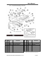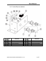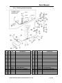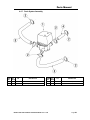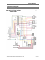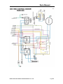
1
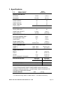
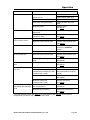
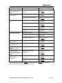
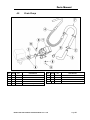
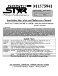
MODEL CMA-180UC SERVICE & PARTS MANUAL Rev 1.18B CMA DISHMACHINES 12700 KNOTT STREET GARDEN GROVE, CALIFORNIA 92841 800-854-6417 FAX 714-895-2141 www.cmadishmachines.com TABLE OF CONTENTS MODEL CMA-180UC 1. SPECIFICATIONS ........................................................................................ 2 1.1. CMA-180UC ......................................................................................................................... 2 1.2. CMA-180UC OPERATIONAL CYCLE ...................................................................................... 3 2. GETTING STARTED..................................................................................... 5 2.1. INTRODUCTION TO CMA-180UC ........................................................................................... 5 2.2. RECEIVING AND INSTALLATION.............................................................................................. 6 3. 2.2.1. Electrical ....................................................................................................................... 6 2.2.2. Plumbing........................................................................................................................ 6 2.2.3. BETA Detergent And Rinse Dispenser (Optional). ........................................................ 7 2.2.4. NOVA Detergent and Rinse Dispenser (Optional). ....................................................... 8 2.2.5. Safe Ttemp Feature .......................................................................................................10 2.2.6. Water Tempering Kit ....................................................................................................11 2.2.7. Booster Heater Setup ....................................................................................................12 2.2.8. Installers Checklist .......................................................................................................12 OPERATION ............................................................................................... 13 3.1. INITIAL SETUP .......................................................................................................................13 3.1.1. Dema Valve and Dema Flow Disc (New Models). .......................................................13 3.1.2. Rinse Pressure Regulator (Old Models Prior January 2008).......................................13 3.1.3. Rinse and Wash Temperatures .....................................................................................13 3.1.4. Post Instructions ...........................................................................................................13 3.2. STARTUP PROCEDURES..........................................................................................................13 3.3. OPERATING AND CLEANING INSTRUCTIONS ..........................................................................14 3.4. PREVENTIVE MAINTENANCE CHART .....................................................................................15 3.5. QUICK SERVICE GUIDE ...........................................................................................................16 3.6. TROUBLESHOOTING ...............................................................................................................17 4. PARTS MANUAL ........................................................................................ 20 4.1. INITIAL PARTS KIT (P/N 1100.66) .........................................................................................20 4.2. DRAIN PUMP .........................................................................................................................21 4.3. DRAIN PUMP REMOVAL INSTRUCTIONS ................................................................................22 4.4. MECHANICAL DRAWINGS ......................................................................................................23 4.4.1. Cabinet Assembly..........................................................................................................23 4.4.2. Door Assembly ..............................................................................................................24 4.4.3. Electrical Tray ..............................................................................................................25 4.4.4. Control Box Assembly p/n 18611.61.............................................................................26 4.4.5. Chemical Dispenser (Optional) ....................................................................................27 4.4.6. Plumbing System Assembly...........................................................................................28 www.cmadishmachines.com 5. 4.4.7. Drain System Assembly.................................................................................................29 4.4.8. Wash System .................................................................................................................30 4.4.9. Rinse System .................................................................................................................31 4.4.10. S/S Pump Assembly (Effective August 2009) ................................................................32 4.4.11. Pump System Assembly .................................................................................................33 4.4.12. Old Heater Assembly (Square Flange) .........................................................................34 4.4.13. New Heater Assembly (Triangular Flange)..................................................................35 4.4.14. Drain Valve...................................................................................................................36 4.4.15. Drain Valve (Effective January 2011) ..........................................................................37 ELECTRICAL DIAGRAM ............................................................................ 38 www.cmadishmachines.com 1. Specifications 1.1. METRIC EQUIVALENT CMA-180UC WATER CONSUMPTION PER RACK .75 GAL. (2.83 L) PER HOUR 17.9 GAL. (67.6 L) WASH TIME-SEC 94 94 RINSE TIME-SEC 16 16 DWELL TIME-SEC 10 10 2 MIN. 2 MIN. 30 30 WASH TANK CAPACITY 2.5 GAL. (9.46 L) PUMP CAPACITY 38 GPM (144 LPM) REQUIRED MINIMUM TEMP. * 110°F (43°C) RECOMMENDED TEMP. ** 140°F (60°C) WATER INLET ½” 1.27cm DRAIN CONNECTION 1” 2.54cm OPERATING CYCLE TOTAL CYCLE OPERATING CAPACITY RACKS PER HOUR WATER REQUIREMENTS RINSE PRESSURE SET 2 20 PSI±5 PSI 1.41 kg/cm WASH-°F 150°F -160°F (65.5°C/71°C) RINSE -°F 180°F -195°F (82°C/90°C) CYCLE TEMPERATURES FRAME DIMENSIONS DEPTH 25” (63.5 cm) WIDTH 24” (60.96 cm) HEIGHT 33 ¼” (84.45 cm) MAX CLEARANCE FOR DISHES 14.5” (36.8 cm) 208 VOLTS 1 PH—60 Hz 230 VOLTS 1 PH—60 Hz 33 AMPS 35 AMPS 5.3 kW 6.5 kW ¾ HP ¾ HP ELECTRICAL RATING* BOOSTER HEATER WASH PUMP MOTOR THIS SYSTEM REQUIRES THREE POWER WIRES, WHICH INCLUDES A CURRENT CARRYING NEUTRAL. AN ADDITIONAL FOURTH WIRE MUST BE PROVIDED FOR MACHINE GROUND. SHIPPING WEIGHT 234# (106 kg) * For machines having "SAFETY TEMP" feature. ** For faster heat recovery. MODEL CMA-180UC SERVICE & PARTS MANUAL Rev. 1.18B Page 2 1.2. CMA-180UC Operational Cycle The CMA-180UC Operational Cycle has a total cycle time of 2 minutes (120 seconds). The Timing Diagram and the steps listed below detail the individual functions that are executed during each Operational Cycle. Seconds: 0 10 20 30 40 50 60 70 80 90 100 110 120 Instant Start Relay Cam Timer Motor Cam Rinse Cycle Cam Wash Cycle Cam Optional Drain Pump Cam Safe-TTemp Cam 1. With the machine powered up toggling the START switch begins a cycle. a) Toggling the START switch energizes both the Cam Timer motor and the Instant Start Relay. The Instant Start Relay latches ON the power to the Cam Timer motor so that the START switch can be released a moment after it has been toggled without the Cam Timer motor losing power. b) After about 1.5 seconds the Cam Timer’s first cam—the Cam Timer Motor Cam— latches ON the power to the Cam Timer motor and drops out the Instant Start Relay. The Cam Timer motor continues to run for a total of 2 minutes, at which time it switches OFF—resetting the Cam Timer—and waits for the next START command. 2. The Cam Timer’s third cam controls the Wash Pump. The Wash Pump comes ON about 3 seconds into the Operational Cycle and continues to run for 94 seconds. This 94-second period is the Wash Cycle. 3. At the same time that the Wash Pump comes ON the Cam Timer’s fourth cam powers ON the Optional Drain Pump—if one is present—and keeps it running for about 7 seconds before powering OFF. This cam turns ON again midway through the Rinse Cycle and stays ON for 10 seconds, turning OFF 2 seconds after the Rinse Cycle has completed. 4. About 3 seconds after the Wash Cycle has completed the Cam Timer’s second cam, which controls the Rinse Cycle, turns ON—energizing the Water Solenoid—and stays ON for 16 seconds. This 16-second period is the Rinse Cycle. MODEL CMA-180UC SERVICE & PARTS MANUAL Rev. 1.18B Page 3 5. When the cam timer assembly approaches the final rinse portion of the cycle, the “Safe-TTemp” sixth micro switch will pause cam timer assembly if the booster heater has not reached 180 degrees. Machine will remain in wash cycle mode until 180-degree rinse temperature is reached, and at this time the cam timer will advance automatically into the rinse cycle and dispense 180 degrees rinse water over the dishes. MODEL CMA-180UC SERVICE & PARTS MANUAL Rev. 1.18B Page 4 Getting Started 2. Getting Started 2.1. Introduction to CMA-180UC The CMA-180UC is a hot water sanitizing, single rack, under-counter dishmachine. It is a standalone machine featuring a self-contained booster heater. The only external connections necessary are power supply, water supply, drainpipe, and optional chemical dispensers. The machine uses re-circulated wash water and fresh water final-rinse. Operation of the CMA-180UC is extremely user friendly. To initially fill the machine each day, push the switch marked “FILL”. The machine is full when water begins to flow into the scrap tray. The booster tank heater will maintain the wash water temperature at 155°F. The booster heater will produce a minimum of 180°F final rinse water each cycle. The supply water to the CMA-180UC must be a minimum of 140°F at 24 PSI (Pounds per Square Inch) with a 6 GPM (Gallons Per Minute) flow rate and 60 GPH (Gallons Per Hour) recovery rate. The pipe supplying the water must be ½” minimum. The plumbing connection is located at the back of the machine. (See specification sheet on page 2). The drain is a 1" barbed fitting on the back of the machine for easy attachment of your drain hose. The machine retains the features of the standard CMA-180 Series in that it has a scrap tray and the manner in which the tank is filled ensures that the dishes are always rinsed with fresh water instead of re-circulated water. The CMA-180UC is the first under-counter dishmachine of its kind to discharge soil from the wash tank into a scrap tray outside of the wash chamber. This feature keeps the wash water much cleaner over long periods of time. The scrap tray may be emptied on a periodic basis without interruption of the flow of work, thereby providing a much cleaner environment for the wash and rinse cycle. There are also enhancements that can be chosen when required such as drain pump kits and other accessories. Refer to Section 4 “Parts Manual” for the parts list and accessories available for the machine. This manual is structured to provide a complete reference guide to the CMA-180UC. It is presented in a manner that all users will be able to comprehend and use as an effective tool in supporting the operation and maintenance of the dishmachine. The first section explains how the machine is packaged and what to look for when receiving the machine. After unpacking the machine, this manual explains how to install and set up the machine for use. Requirements are given for plumbing, wiring, and space considerations. These attributes of the machine are always taken into consideration by our well-trained sales representatives prior to the order being placed. In the manual, guidance is also given for installation to ensure that the machine will be able to run at optimum conditions. The Operation Section of the manual may be used for instruction and procedures when required. We make this portion of the manual easy to understand so that all levels of operators may be able to read and comprehend the operation of the machine. The function of the machine itself is mostly automatic and takes little training to put into full operation. The Operation Section also includes diagnostic considerations for the machine when problems occur. The next section of the manual is the Parts Manual.This section has the parts lists and wiring diagram for the machine. We are committed to providing the best machines and customer service in the food industry and your feedback is welcome. MODEL CMA-180UC SERVICE & PARTS MANUAL Rev. 1.18B Page 5 2.2. Receiving and Installation The dishwasher is shipped from the factory in a corrugated box on a wooden pallet. The installation guidelines give a systematic procedure for setting up the machine. Start by removing the packaging material. Unwrap the machine and check for the following component parts: The Wash Tank Scrap Screen is shipped inside the wash cavity of the machine. This screen must be in place during operation. It has been designed to perform two basic functions: 1. Strain water that is circulating through the spray arms and pump assembly. 2. A basket to catch broken glass, or heavy solids that may plug the impeller. Set the machine in place, and level from side-to-side and front-to-back. 2.2.1. Electrical 1 A 50-amp, single-phase 230 volt, 60 Hz dedicated circuit should be used to supply electrical energy to the CMA-180UC dishwasher (see specification sheet page 2). This system requires three power wires, which include a current carrying neutral. An additional fourth wire must be provided for ground. CMA and local codes require the CMA-180UC to be hardwired using #8 AWG (90°C) copper wire (minimum). Approximately 4-feet of ¾” flexible conduit with power leads (L-1, L-2, Neutral and Ground) extending out of the conduit are provided for easily connecting the power at installation. The power connection must be located such that there is sufficient length of the flexible conduit remaining to permit the machine to be moved for cleaning. 2.2.2. Plumbing2 The machine is equipped with a ½” NPT connection located at the lower left-hand corner (facing the back) of the machine. A 140°F water line should be plumbed to this point (see specification sheet page 2). The water line used must be of sufficient length and flexibility to permit the machine to be moved for cleaning. Important: New machines equipped with Dema Valve and Dema Flow Disc require an unrestricted water supply line minimum of ½”. The supply water to the CMA-180UC must be a minimum of 140°F at 24 PSI (Pounds per Square Inch) with a 6 GPM (Gallons Per Minute) flow rate and 60 GPH (Gallons Per Hour) recovery rate. The pipe supplying the water must be ½” minimum. The plumbing connection is located at the back of the machine. (See specification sheet on page 2). The CMA-180UC may be supplied with an optional drain pump for elevated drains. For floor gravity drain applications the drain pump should not be used and a good commercial grade hose needs to be connected to the discharge side of the diverter valve (drain valve) and run to the floor drain. If removing a drain pump, safe-end (insulate electrically) the white and purple wires and secure them out of the way. If a drain pump is used with a floor drain, the drain hose must rise 12 to 16” before dropping to the floor drain (to reduce any chance of the pump cavitations). Warning: If the water hardness is greater than 3 grains per gallon, a water softener is required to prevent damage to heating elements (scale build- up) and booster tank rinse flow restriction. Rinse flow restriction will cause the booster tank to expand and contract causing metal flex, which will eventually crack the tank. 1,2 All electrical and plumbing connections must be made by a qualified person who will comply with all available Federal, State, and Local Health, Electrical, Plumbing and Safety codes MODEL CMA-180UC SERVICE & PARTS MANUAL Rev. 1.18B Page 6 2.2.3. BETA Detergent And Rinse Dispenser (Optional). Optional built-in Beta dispenser (CMA p/n 14585.00) has easy access for chemical settings behind the front kick panel. Both initial charge and recharge are factory pre-set. Basic settings for both detergent and rinse speed are 50%. Operating fine-adjustment screws on the dispenser can control the amount of chemicals drawn into chemical lines. Undercounter machine with the optional dispenser must be ordered separately, as option at time of order. Optional dispenser has to be pre-wired prior to shipment (see electrical diagram for wiring options). MODEL CMA-180UC SERVICE & PARTS MANUAL Rev. 1.18B Page 7 2.2.4. NOVA Detergent and Rinse Dispenser (Optional) 1. The NOVA Detergent and Rinse Dispenser has its own reference manual. Familiarize yourself with the dispenser’s reference manual before proceeding with installation. 1. The NOVA dispenser is pre-wired with a multi-conductor electrical cable that is to be run through a conduit to the power block inside the control panel drawer. Use a ½” watertight conduit meeting all local and national codes. A conduit fitting is present on the bottom of the dispenser where the power cable exits. A mounting plate to receive the ½” conduit is provided on the top right-hand corner (facing the back) of the machine. i. Run an appropriate length of ½” conduit from your dispenser to the mounting plate where it will be secured. The conduit needs to be of sufficient length and flexibility to permit the machine to be moved for cleaning without having to disconnect any wiring. ii. Run your dispenser wires through the conduit and through the enclosed area across the top of the machine and then feed them through the access hole provided in the back of the control panel drawer. iii. With the machine’s power “OFF”, connect your detergent and rinse dispenser wires to the power block supplied and labeled (“DISPENSER 110V - 3 AMPS MAX”) inside the control panel drawer. The table that follows lists the function of each conductor of the multi-conductor electrical cable. Wire Colors Circuit Voltage Function Gray/Violet Black Brown 90 VAC-130 VAC 50/60 Hz 90 VAC-130 VAC 50/60 Hz No Connection. Insulate this wire! Main AC Power Main AC Power This wire is LIVE! Yellow White/Yellow 90 VAC-130 VAC 50/60 Hz 90 VAC-130 VAC 50/60 Hz Detergent Signal Detergent Signal Violet White/Violet 90 VAC -130 VAC 50/60 Hz 90 VAC -130 VAC 50/60 Hz Rinse Signal Rinse Signal The individual conductors need to be connected as shown in Figure 2.2.4 and as described on next page. 1 All electrical and plumbing connections must be made by a qualified person who will comply with all available Federal, State, and Local Health, Electrical, Plumbing and Safety codes MODEL CMA-180UC SERVICE & PARTS MANUAL Rev. 1.18B Page 8 Brown (LIVE) wire Multi-conductor cable Rinse Signal wires (Blue terminals) Detergent Signal wires (Red terminals) Black (Main Power) Gray/Violet (Main Power Neutral) (Same terminal as rinse neutral) Note: Machine Neutral (White wires) Figure 2.2.4 Note: In Figure 2.2.4 the machine’s wire harness was left out of the back of the power block to more clearly show the dispenser wires. 2. Remove the plug from the mixing chamber located by the vacuum breaker on the back of machine; and install the rinse injection fitting (supplied with your dispenser). See Figure 2.2.4. Figure 2.2.4. 3. A 7/8" detergent injection hole is provided in the back of the wash tank. Remove the S.S. plug and install the detergent fitting (supplied with your dispenser). 4. The final step of installing the CMA supplied Detergent and Rinse Dispenser is programming it to your specific application. The reference manual supplied with the dispenser shows you how to program it. Keep in mind while reading the reference manual that the CMA-180UC operates in “probe-less” mode. (This mode is selected by setting a value of “2” in screen 21). Screen 22 must be set to “1” (Door). MODEL CMA-180UC SERVICE & PARTS MANUAL Rev. 1.18B Page 9 2.2.5. Safe Ttemp Feature The CMA “SafeTtemp” feature assures the final rinse cycle is always at a consistent minimum of 180 degrees. th How it works: the “SafeTtemp” function operates off the 5 cam (labeled “SafeTtemp”) on the timer assembly. When the cam timer assembly completes the wash cycle, and approaches the final rinse portion of the cycle, the “SafeTtemp” micro switch will drop into the cam slot and pause cam timer assembly if the booster heater has not reached 180 degrees. Machine will remain in wash cycle mode until 180 degree rinse temperature is met, and at this time the cam timer will advance automatically into the rinse cycle and dispense 180 degrees rinse water over the dishes. Note: if Safe Ttemp cam is not to be used, it becomes a spare cam. CMA -180“SafeTtemp” Installation Instructions: 1) Remove the 4cam timer assembly (note wire colors and wire placement for all 4cam timer micro switches) and install 5cam timer in its place. 2) Place all wires removed from 4cam timer assembly in exact position on 5cam timer assembly. 3) The cam timer motor receives (1) yellow wire and (1) white wire (re-connect the yellow wire only from dishmachine harness to the motor). 4) The “SafeTtemp” 5 cam timer assembly kit includes a two white harness – connect white wire with female bullet connector to the timer motor, stripped end to #22/NC on contactor, th and spade end to center terminal 5 micro switch. 5) Connect white wire with male bullet connector from the kit to the white wire with female bullet connector coming from dishmachine harness, stripped end to #21/NC on contactor, th and spade end to top terminal on 5 micro switch. L1 L2 L3 HEATER CONTACTOR T1 T2 SafeTtemp harness T3 21 A1 N/C 22 A2 Dishmachine harness Female bullet connector Male bullet connector Female bullet connector Male bullet connector MODEL CMA-180UC SERVICE & PARTS MANUAL Rev. 1.18B Page 10 2.2.6. Water Tempering Kit MODEL CMA-180UC SERVICE & PARTS MANUAL Rev. 1.18B Page 11 2.2.7. Booster Heater Setup The booster tank must be filled with water before the heating element is energized. For this reason the “High Limit Switch” has intentionally been disconnected at the factory and will require re-connection before the heating element will turn on. Follow the procedure below to complete the initial installation: 1. Close the door on the machine. 2. Turn the Power switch to the "ON" position. 3. Hold the “FILL” switch in until water overflows into the scrap tray. 4. Turn the Power switch to the "OFF" position. 5. Connect blue wire with disconnect, identified by red tag, to the High Limit Switch which is located behind the thermostat behind the front kick panel. 2.2.8. Installers Checklist Dishmachine checked for concealed damage Hot water supply is 140° F (60 C) — minimum Incoming water supply line is ½” — minimum Incoming water supply is 6 GPM minimum at 24 PSI Supply circuit breaker for machine is properly sized (50 amp) Service voltage and phase type are correct to machine data plate If drain pump is used, drain hose rises 12 to 16” before dropping to drain Drain hose is installed with air gap (discharge 1” above drain) Optional detergent and rinse dispenser (if present) is properly installed Dishmachine is properly grounded Dishmachine is properly leveled Machine circuit breaker is labeled “DISHWASHER” Machine has been “hard-wired” with correctly sized wire Booster tank has been filled with water (before High Limit Switch is reset) High Limit Switch for heater has been reset (after Booster Tank has been filled) MODEL CMA-180UC SERVICE & PARTS MANUAL Rev. 1.18B Page 12 Operation 3. Operation 3.1. Initial Setup 3.1.1. Dema Valve and Dema Flow Disc (New Models). New Dema Valve made of stainless steel is more compatible with various water conditions. Dema Flow Disc has been placed on the exit side of the water valve. The Flow Disc reduces pressure to the standard recommended 20 PSI. 3.1.2. Rinse Pressure Regulator (Old Models Prior January 2008). The CMA-180UC requires a supply water input pressure of 24 PSI minimum. This pressure is then reduced by the supply water regulator. Use the following procedure to adjust the rinse pressure to 20 PSI: 1. Close the door on the machine. 2. Turn the Power switch to the "ON" position. 3. While holding the “FILL” switch—to activate the water solenoid—adjust the pressure regulator until the gauge reads 20 PSI. (Regulator is located behind the front kick panel). 3.1.3. Rinse and Wash Temperatures 1. Turn the Power switch to the "ON" position. 2. After the machine has warmed up for about ten-minutes, note the wash and rinse temperatures. The wash temperature must be 155°F minimum. The 3 rinse temperature must be 180°F minimum . If necessary, adjust the temperatures by removing the front kick panel and turning the thermostat adjustment clockwise to increase, counterclockwise to decrease. This one adjustment controls both temperatures. 3.1.4. Post Instructions 1. Install wall chart and instruct machine operator on proper cleaning and operation of the CMA-180UC. 3.2. Startup Procedures 1. Open the door of the machine and check that the scrap screen is in place, and that the spray arms and end plugs are secure. 2. Close the door of the machine and turn the Power switch to the "ON" position. 3. Hold the fill button about 25 seconds or until the water overflows into the scrap tray. 4. Once the water is filled to the proper level, press the rocker switch marked “START” – the machine will automatically begin its cycle. 5. Check machine’s operating temperatures — Adjust if necessary. See section 3.1.3 Rinse and Wash Temperatures. 6. At the end of the wash period, drain the machine by pushing the rocker switch marked “DRAIN”. Clean the wash tank screen and scrap tray screen. Remove and clean the spray arms. (See wall chart instructions). 3 Rinse cycle temperature must be observed during a rinse MODEL CMA-180UC SERVICE & PARTS MANUAL Rev. 1.18B Page 13 Operation 3.3. Operating and Cleaning Instructions MODEL CMA-180UC SERVICE & PARTS MANUAL Rev. 1.18B Page 14 Operation 3.4. Preventive Maintenance Chart MODEL CMA-180UC SERVICE & PARTS MANUAL Rev. 1.18B Page 15 Operation 3.5. Quick service guide MODEL: CMA 180UC HIGH TEMP UNDER COUNTER TECHNICAL ISSUE CAUSE SOLUTION Pressure regulator is not set properly Set regulator to 18-20 psi Faulty rinse micro switch Replace micro switch, P/N 00411.00 Drain hose elevated too high Must be lowered to goose neck level Obstruction in drain hose Check hose & clean Scrap exit screen Clean exit screen Faulty drain pump Replace pump, P/N 15503.00 Machine not level Adjust machine legs to level Machine is leaning forward Adjust machine legs to level Wash arm end cap missing Replace end cap, P/N 00308.20 Door gasket Loose wire at display, board or transformer Replace gasket, P/N 14506.60 Secure connectors Faulty temperature sensing wire Correct, replace, P/N 03202.66 Faulty temperature sensing unit Replace unit, P/N 03203.00 Faulty transformer Replace transformer, P/N 03202.60 Clean scale from heater Adjust thermostat Rinse water temperature low /high Scaled heating element Booster heater’s thermostat not properly set Incoming water temperature to booster heater below 140 F Adjust external water heater in the facility Pump motor not running Loose lead connections Faulty # 3 micro switch Check and crimp connectors Replace micro switch, P/N 00411.00 Faulty contactor Replace contactor, P/N 15504.00 Faulty wash pump motor Faulty # 3 micro switch Replace wash pump motor, P/N 00201.00 Replace micro switch, P/N 00411.00 Scrap trap over flows Door leaks Thermometer failure Pump motor runs continuously Faulty contactor Replace contactor, P/N015504.00 Water regulator not adjusted properly Adjust regulator to 18-20 PSI Low water pressure at the final rinse Scrap trap overflows over night Poor cleaning results Wash tank will not drain. Clogged final rinse spray jets Missing final rinse spray end cap Clean jets Replace end cap, P/N 00308.17 Low incoming water pressure from facility Increase pressure to 18-20 psi Faulty water solenoid diaphragm Clean or replace diaphragm, P/N 00706.00 Low wash or rinse water temp. Check temperature settings Wash arm bearing or jets Clean bearing and arm jets Rinse arm bearing or jets Tank discharge screen dirty Clean bearing and arm jets Clean screen Drain valve not operating Check power to drain valve Drain valve faulty Replace Drain valve, P/N 04103.00 MODEL CMA-180UC SERVICE & PARTS MANUAL Rev. 1.18B Page 16 Operation 3.6. Troubleshooting PROBLEM LIKELY CAUSE SOLUTION Machine inoperative Power off at circuit breaker Reset circuit breaker Defective power switch Replace power switch P/N: 15521.50 Motor inoperative Door is open Close door Control panel is pulled out Secure control panel Defective reed switch Replace reed switch P/N: 00557.55 Defective timer assembly Replace timer assembly* P/N: 14408.80 Defective pump motor contactor Replace contactor P/N: 15504.00 Defective motor Replace motor P/N: 00201.66 Motor runs with door open Defective reed switch Replace reed switch P/N: 00557.55 Defective pump motor contactor Replace contactor P/N: 15504.00 Heater (no heat) High limit switch opened or defective P/N: 17523.51 Reset or replace switch Defective thermostat Replace thermostat P/N: 13417.89 Defective heater contactor Replace heater contactor P/N: 15504.50 Defective heater Replace heater P/N: 15517.00 Heater (never turns off) Defective thermostat Replace thermostat P/N: 13417.89 Defective heater contactor Replace heater contactor P/N: 15504.50 *The timer assembly motor (P/N: 00501.00) or micro switches (P/N: 00411.00) can be replaced independently if that’s the only component that’s failed. MODEL CMA-180UC SERVICE & PARTS MANUAL Rev. 1.18B Page 17 Operation PROBLEM LIKELY CAUSE SOLUTION Low heat during operation Low incoming water temperature Turn up supply water heater (below 140° F) Insulate supply water pipe Thermostat out of adjustment Adjust thermostat Cold water mixing with supply Isolate hot water from cold water Defective heater Replace heater P/N: 15517.00 Low rinse water pressure Regulator at maximum but rinse pressure still low Pressure regulator out of adjustment Adjust pressure regulator Defective pressure gauge (actual pressure is okay) P/N: 13605.45 Insufficient water supply flow Supply larger supply line Defective water solenoid valve Replace pressure gauge Replace water solenoid valve P/N: 03603.10 Low rinse water flow No rinse water flow Low rinse water pressure See “Low rinse water pressure” in PROBLEM column Limed up rinse arm spray nozzles De-lime rinse arm nozzles Defective water solenoid valve Replace water solenoid valve P/N: 03603.10 Defective (Rinse Relay) ice cube relay Replace ice cube relay Rinse water runs with door open Defective reed switch Replace reed switch Water overflows scrap tray onto floor Drain hose is kinked Un-kink drain hose Drain hose is not properly elevated before dropping to drain (if drain pump is used) Elevate drain hose 12 to 16” above pump before dropping to drain P/N: 00631.00 P/N: 00557.55 Defective timer assembly Replace timer assembly* P/N: 14408.80 Defective drain pump (if drain pump is used) With power on, activating start switch does not begin cycle Replace drain pump P/N: 15503.00 Defective start switch (cycle light will not light either) Replace start switch Defective timer assembly Replace timer assembly* P/N: 15521.00 P/N: 14408.80 *The timer assembly motor (P/N: 00501.00) or micro switches (P/N: 00411.00) can be replaced independently if that’s the only component that’s failed. MODEL CMA-180UC SERVICE & PARTS MANUAL Rev. 1.18B Page 18 Operation PROBLEM LIKELY CAUSE SOLUTION Start switch requires > 1 second activation to run cycle Defective (Instant Start) ice cube relay P/N: 00631.00 Activating fill switch does not fill machine Defective drain/fill switch Replace drain/fill switch Replace ice cube relay P/N: 15522.00 Defective water solenoid valve Replace water solenoid valve P/N: 03603.10 Fill (rinse water) won’t shut off Defective water solenoid valve Replace water solenoid valve P/N: 03603.10 Defective drain/fill switch Replace drain/fill switch P/N: 15522.00 Defective timer assembly Replace timer assembly* P/N: 14408.80 Activating drain switch does not drain machine Defective (Rinse Relay) ice cube relay Replace ice cube relay Drain hose is kinked Un-kink drain hose Defective drain/fill switch P/N: 00631.00 Replace drain/fill switch P/N: 15522.00 Defective drain valve Replace drain valve P/N: 04103.00 Cycle light does not light while cycle runs Defective cycle light Power light does not light but machine runs Defective power light Wash tank or final rinse temperature does not display Defective digital thermometer Both the wash tank temperature and the final rinse temperature do not display Defective thermometer transformer Wash tank or final rinse displays wrong temperature Defective digital thermometer Replace cycle light (green) P/N: 00406.60 Replace power light (red) P/N: 00406.00 Replace digital thermometer P/N: 03202.45 Replace thermometer transformer P/N: 03202.60 Replace digital thermometer P/N: 03202.45 Defective thermister Replace thermister P/N: 03202.65 *The timer assembly motor (P/N: 00501.00) or micro switches (P/N: 00411.00) can be replaced independently if that’s the only component that’s failed. MODEL CMA-180UC SERVICE & PARTS MANUAL Rev. 1.18B Page 19 Parts Manual 4. Parts Manual 4.1. Initial Parts Kit (P/N 1100.66) P/N DESCRIPTION Qty 15504.00 Motor Contactor, 2-Pole 20 Amp 1 15504.50 Heater Contactor, 2-Pole 35 Amp 1 00501.00 2-Minute Timer Motor 1 00631.00 Ice Cube Relay 120 V 1 15523.00 Rocker Switch Start Momentary 1 15523.50 Rocker Switch Drain/Fill 1 15524.00 Rocker Switch Power Maintained 1 00556.10 Reed Switch 1 03623.00 1/2” Vacuum Breaker Repair Kit – Watts 1 00707.00 1/2” Water Solenoid Repair Kit – J/E 1 04113.00 L1X/L1-C Drain Valve 120V 1 00206.30 Pump Seal Kit 1 13417.89 Heater Thermostat 1 17523.60 High Limit Switch 200°F 1 00411.00 Microswitch 1 03202.66 Thermocouple (Control Products) 1 03604.30 Dema Valve Repair Kit 3/8",1/2" & 3/4 41015.60 Water Solenoid Coil Only 110V MODEL CMA-180UC SERVICE & PARTS MANUAL Rev. 1.18B Page 20 Parts Manual 4.2. ITEM NO. NO. REQ’D Drain Pump P/N DESCRIPTION ITEM NO. NO. REQ’D P/N DESCRIPTION 1 1 15503.00 Drain Motor Ultra Jet for CMA-180UC 6 4 03101.00 Hose Clamp 1” 2 2 00932.50 Twist Tie 7 1 15603.00 Drain Line Gooseneck 3 1 15601.10 Black Drain Hose 1" ID X 3 1/2" 8 2 03801.10 10-32 SS Nut 4 1 15605.00 Drain Hose with Goose Neck 9 2 04806.00 #10 Brass Washer 5 1 15601.60 Robber Hose 90 Deg. MODEL CMA-180UC SERVICE & PARTS MANUAL Rev. 1.18B Page 21 Parts Manual 4.3. Drain Pump Removal Instructions Drain Pump (P/N 15503.00) should only be used if a floor drain is not accessible to the machine at installation. When converting the UC-180 dishwasher to a gravity drain unit, remove the drain pump assembly as shown in Figure 1. Re-route the 6Ft drain hose to the center port were the drain pump was located, moving the displaced line to the open port of the valve. Insure there is a 1” air gap between the discharge and floor drain as shown in Figure 2. Disconnect purple and white wires Remove this cover to disconnect the wires Remove this hose clamp over Drain Valve. Remove drain hose from the drain gooseneck Disconnect 3inch pump inlet drain hose. Figure 1 Figure Figure 2 MODEL CMA-180UC SERVICE & PARTS MANUAL Rev. 1.18B Page 22 Parts Manual 4.4. Mechanical Drawings 4.4.1. Cabinet Assembly ITEM NO. NO. REQ’D 1 2 3 4 5 6 7 8 9 10 11 12 13 14 15 1 1 1 1 1 1 1 1 1 4 1 1 6 8 4 P/N DESCRIPTION 14502.82 14508.10 14503.50 14510.00 14511.00 14512.00 14515.00 14560.00 14501.20 01310.60 14506.50 14506.45 00940.50 00941.00 03801.00 Side Panel L.H. for CMA-180UC Peri Pump Front R Side Cover(180-UC) SS Top for CMA-180UC Scrap Basket for CMA-180UC Tray Track R.H. for CMA-180UC Tray Track L.H. for CMA-180UC Lower Front Panel for CMA-180UC Scrap Tray Drawer for CMA-180UC SS Body for CMA-180UC Leg Adjusters for CMA-180UC * Door Gasket for CMA-180UC Gasket Bracket for CMA-180UC 10-32 x 3/8 Trusshead Screw 10-32 x 5/8 Panhead Screw 10-32 Lock Nut ITEM NO. NO. REQ’D 16 17 18 19 20 21 22 23 24 25 26 27 28 29 30 MODEL CMA-180UC SERVICE & PARTS MANUAL Rev. 1.18B 4 1 1 1 2ft 1 2 2 2 1 1 1 1 4 4 P/N DESCRIPTION 00940.51 01513.00 00752.00 00912.00 03705.84 14558.00 00557.80 00927.00 04806.00 00214.30 14561.00 03415.00 14508.20 01147.50 01147.00 #10 Internal Lock Star Washer Detergent Injection Hole Plug Detergent Injection Hole Plug Gasket 1/4”-20 Nylon Lock Nut Control Box Gasket for CMA-180UC Body Magnet Holder for CMA-180UC Magnet for CMA-180UC 8-32 Lock Nut #10 Brass Flat Washer 1/4" Compression x 3/8” MIP Fitting Scrap Trap Filter (CMA 180-UC) Chemical Bulk Head Peri Pump Back R Side Cover(180-UC) Leg 4" 1/2-13 1" Diameter (UC) ^Leg 6" 1/2"-13 1" Diameter (UC) Page 23 Parts Manual 4.4.2. Door Assembly ITEM NO. NO. REQ’D P/N DESCRIPTION ITEM NO. NO. REQ’D P/N DESCRIPTION 1 1 14506.00 Door for CMA-180UC 10 1 14558.61 Door Magnet Holder for CMA-180UC 2 2 04517.60 Door Support Rod Block 11 2 00965.00 6-32 Lock Nut 3 1 14570.00 Door Hinge R.H. for CMA-180UC 12 2 00605.20 Door Rod Spacer 4 1 14570.50 Door Hinge L.H. for CMA-180UC 13 2 04517.15 Door Stop (Parallel) 5 2 04919.00 Door Rod Screw Pin for CMA-180UC 14 10 00912.00 1/4”-20 Nylon Lock Nut 6 1 04918.60 Door Support Rod Right 15 14 00924.00 1/4” SS Washer 7 1 04919.50 Door Support Rod Left 16 4 00914.10 1/4”-20 x 5/8” Hexhead Bolt 8 3 00557.80 Door Magnet 17 2 14518.00 Splash Guard 9 2 00970.60 6-32 x 1/2” Flathead Screw MODEL CMA-180UC SERVICE & PARTS MANUAL Rev. 1.18B Page 24 Parts Manual 4.4.3. Electrical Tray ITEM NO. NO. REQ’D 1 2 3 4 5 6 7 1 1 1 1 1 2 2 P/N 14504.00 14408.81 15504.00 15504.50 15520.50 00438.00 01001.00 DESCRIPTION Electrical Tray for CMA-180UC Timer 2Min 5 Cam 180-UC S.T Motor Contactor, 2-Pole 20 Amp Heater Contactor, 2-Pole 35 Amp Power Block, 3-Position Snap Bushing, Universal 6-32 x 1” Panhead Screw ITEM NO. NO. REQ’D 8 9 10 11 12 13 MODEL CMA-180UC SERVICE & PARTS MANUAL Rev. 1.18B 12 1 2 1 9 1 P/N 00927.00 13426.60 00965.00 00401.85 00400.85 13304.61 DESCRIPTION 8-32 Nylon Lock Nut Ground Block 6-32 Lock Nut 3/4” Conduit Connector, Straight 3/4” Conduit, Sealtite HT Plumbing Bracket Page 25 Parts Manual 4.4.4. Control Box Assembly p/n 18611.61 ITEM NO. NO. REQ’D P/N DESCRIPTION ITEM NO. NO. REQ’D P/N DESCRIPTION 1 1 15520.00 Power Block 12-Position 12 2 00965.00 6-32 SS Nylon Lock Nut 2 2 00631.00 Ice Cube Relay 120 V 13 5 00927.00 8-32 Nylon Lock Nut 3* 1 03203.01 Dual Temperature Display Kit 14 6 00911.00 8-32 x 1/2” Panhead Screw 4 1 03202.60 Thermometer Transformer 15 1 00556.10 Reed Switch 5 1 14503.00 Control Drawer for CMA-180UC 16 4 00917.00 8-32 PM Nut 6 1 15523.00 Rocker Switch Start Momentary * 17 2 03705.82 Sponge Strip 7 1 15523.50 Rocker Switch Drain/Fill DPDT/Mom. * 18 2 03202.66 Thermocouple 8 1 15524.00 Rocker Switch Power Maintained * 19 2 00971.10 4-40 Nylon Lock Nut 9 1 13426.50 Ground Block 20 1 03485.00 Switch Guard (Undercounter) 10 1 00438.00 Snap Bushing, Universal 21 1 06232.61 CMA180-UC Panel Label 11 2 01001.00 6-32 x 1” Panhead Screw *Switch covers for the switches p/n 3481 00 421 41 MODEL CMA-180UC SERVICE & PARTS MANUAL Rev. 1.18B Page 26 Parts Manual 4.4.5. Chemical Dispenser (Optional) ITEM NO. NO. REQ’D 1 2 3 4 5 6 7 2 2 2 2 1 2 2 P/N DESCRIPTION 00816.00 00818.00 00839.00 00815.00 00821.00 00820.20 00820.00 Peri Pump Gear Motor (GL-C/GW-100) GL-C/GW-100 Peri Pump Cartridge GL-C/GW-100/UC180 Sqz Tube w/ Con. GL-C Peri Pump Complete GL-C/GW-100 Transformer Circuit Board Connector GL-C/GW-100 Peri Pump Circuit Board ITEM NO. NO. REQ’D 8 9 10 11 12 13 14 MODEL CMA-180UC SERVICE & PARTS MANUAL Rev. 1.18B 4 4 4 2 2 2 1 P/N 13826.47 00820.06 00820.07 13826.00 00820.50 00971.10 14508.00 DESCRIPTION 4-40 x 3/16 Phil Pan Head Screw Circuit Board Standoff Circuit Board Standoff Cap 4-40 X 5/8 Pan Head Screw Circuit Board Stand-off Bushing 4-40 Nylon Lock Nut UC180 Peri Pump Box Page 27 Parts Manual 4.4.6. Plumbing System Assembly ITEM NO. NO. REQ’D P/N DESCRIPTION ITEM NO. NO. REQ’D P/N DESCRIPTION 1 1 15602.00 SS Braided Hose 20" 17 1 00739.50 2 1 00798.00 SS Braided Hose 20" 18 1 03624.25 Vacuum Breaker Bonnet, Brass 3 1 03604.50 Fitting with Flow Disk 19 1 03623.00 1/2” Vac. Breaker Repair Kit – Watts 4 1 03604.10 SS Solenoid Valve Flow Disc 20 2 03614.00 Nipple, Brass 1/2” Close 5 1 03604.00 SS Water Solenoid Valve 1/2" 21 1 03232.00 1/8” Male Plug 6 4 00760.00 5/8” Compression x 1/2” MIP Adapter 22 1 13669.45 SS Mixing Chamber CMA-180UC 7 1 03605.00 Plumbing tube CMA-180UC 23 1 00798.00 1/2” SS Braided Hose 8 2 00940.50 10-32 X 3/8 Truss Head Screw 24 2 00915.00 1/4”-20 SS Nut 9 2 03801.60 10-32 KEPS Lock Nut 25 2 00724.00 1/2” Compression x 1/2” MIP Adapter 10 1 14508.60 Plumbing Bracket (180-UC) 26 1 13304.53 Long Support Bracket 11 1 03604.30 Dema Valve Repair Kit 1/2" 27 1 00798.40 SS Braided Hose 12” 12 1 41062.00 1/2" Strainer Ball Valves * 28 1 13604.10 1/2 x 1/8 Bushing Brass 13 1 00214.60 1/4” Compression x 1/2” MIP FTG 29 1 13605.45 Pressure Gauge for CMA-180UC 14 2 00743.10 1/2" T,FxFxF 30 1 41015.60 Water Solenoid Coil Only 15 1 05007.60 Vacuum Breaker Line 31 1 13658.00 Inlet Check Valve 16 1 03624.00 1/2” Vacuum Breaker – Watts 32 1 41062.10 Ball Strainer MODEL CMA-180UC SERVICE & PARTS MANUAL Rev. 1.18B Vacuum Breaker Cap, SS Page 28 Parts Manual 4.4.7. Drain System Assembly ITEM NO. NO. REQ’D P/N DESCRIPTION ITEM NO. NO. REQ’D P/N DESCRIPTION 1 1 04113.00 Drain Valve 120V 3 2 15601.60 Hose 1” ID 14” Pump to Manifold 2 6 03101.00 Hose Clamp #16-1” 4 1 15601.10 Black Drain Hose 1" ID X 3 1/2" MODEL CMA-180UC SERVICE & PARTS MANUAL Rev. 1.18B Page 29 Parts Manual 4.4.8. Wash System ITEM NO. NO. REQ’D P/N DESCRIPTION 1 2 00304.46 Wash Arm 2 4 00308.20 Wash Arm End Plug ITEM NO. NO. REQ’D MODEL CMA-180UC SERVICE & PARTS MANUAL Rev. 1.18B 3 2 P/N 04305.17 DESCRIPTION Red Silicon Gasket 1/16” Thick Page 30 Parts Manual 4.4.9. Rinse System ITEM NO. NO. REQ’D P/N DESCRIPTION ITEM NO. NO. REQ’D P/N DESCRIPTION 1 2 00304.65 Rinse Arm CMA-180UC 3 2 04305.17 Red Silicon Gasket 1/16” Thick 2 8 N/A SS Final Rinse Spray Jet – HT welded 4 4 00308.17 Rinse Arm End Cap MODEL CMA-180UC SERVICE & PARTS MANUAL Rev. 1.18B Page 31 Parts Manual 4.4.10. S/S Pump Assembly (Effective August 2009) ITEM NO. NO. REQ’D P/N DESCRIPTION ITEM NO. NO. REQ’D P/N DESCRIPTION 1 4 00908.00 5/16”-18 x 5/8” SS Hexhead Bolt 12 2 00238.00 3/8” Male Plug 2 4 00926.00 5/16” SS Washer 13 1 00208.40 Slip Joint Nut O Ring Buna 3 4 00913.00 5/16”-18 Hex Nut 14 1 00207.00 Slip Joint Nut 1 1/2 x 1 1/4 4 1 00201.60 SS Wash Pump Motor 220v 15 1 00200.70 Includes Items 4,5,6,7,8,9,and 11 5 1 00201.96 Slinger Washer Cone Shape 16 1 03222.74 Flat Washer 8 mm 6 1 03224.60 SS Pump Backplate 17 1 03222.72 Shaft Nut Lock Washer 8mm 7 1 03226.70 Volute O-Ring For SS Pump 18 1 13809.70 SS Pump Seal Shaft Nut 8mm 8 1 00206.70 SS Pump Seal Kit 19 6 00914.70 Socket Head Screw 10 mm Slip Joint Nut Friction Ring 9 1 03222.70 SS Pump Impeller 20 1 00208.21 10 1 04604.00 ^35 Deg Elbow MIP X Barb 21 1 03101.00 Hose Clamp # 16 1" 11 1 04206.75 SS Pump Cover 22 1 03108.62 Transfer Hose 1" Reinforce 25" MODEL CMA-180UC SERVICE & PARTS MANUAL Rev. 1.18B Page 32 Parts Manual 4.4.11. Pump System Assembly ITEM NO. NO. REQ’D P/N DESCRIPTION ITEM NO. NO. REQ’D P/N DESCRIPTION 1 4 00908.00 5/16”-18 SS Hexhead Bolt 10 1 04206.00 Pump Cover 2 4 00926.00 5/16” SS Washer 11 1 00208.40 Slip Joint Nut Gasket 3 4 00913.00 5/16”-18 Hex Nut 12 1 04204.00 L-1X Compression Nut 2.5” 4 1 00208.21 Slip Joint Ring 13 1 00213.50 Pump Fitting 5 1 00201.66 Water Pump Motor for CMA-180UC 14 2 00301.00 1” Hose Clamp #16 6 8 00921.00 3/8”-16 x 3/4” Hex Bolt 15 1 03108.62 Transfer Hose 1" Reinforce 25" 7 1 03224.00 Pump Base (Mount) 16 1 03226.00 Pump “O” Ring Gasket 8 1 00206.30 Pump Seal Kit 17 2 00238.00 3/8” Male Plug 9 1 03222.10 Impeller L-1M MODEL CMA-180UC SERVICE & PARTS MANUAL Rev. 1.18B Page 33 Parts Manual 4.4.12. Old Heater Assembly (Square Flange) ITEM NO. NO. REQ’D P/N DESCRIPTION ITEM NO. NO. REQ’D P/N DESCRIPTION 1 1 15517.00 Heater 6kW for CMA-180UC * 6 4 00926.00 2 1 13417.89 Heater Thermostat 7 1 40116.00 5/16” SS Washer 1/4” Compression x 1/4” MIP FTG 3 1 17523.60 High Limit Switch 200°F 8 2 00965.00 6-32 Lock Nut 4 1 15517.10 Heater Gasket 9 2 17524.00 High Limit Switch Spacer 5 4 13805.00 5/16”-18 Nylon Insert Lock Nut *Gasket included MODEL CMA-180UC SERVICE & PARTS MANUAL Rev. 1.18B Page 34 Parts Manual 4.4.13. New Heater Assembly (Triangular Flange) ITEM NO. NO. REQ’D P/N DESCRIPTION ITEM NO. NO. REQ’D P/N DESCRIPTION 1 1 15518.00 Heater 6kW 220V Triangular Flange* 6 3 00926.00 2 1 13417.89 Heater Thermostat 7 1 40116.00 5/16” SS Washer 1/4” Compression x 1/4” MIP FTG 3 1 17523.60 High Limit Switch 200°F 8 2 00965.00 6-32 Lock Nut 4 1 15518.10 Gasket for Triangular Flange Heater 9 2 17524.00 High Limit Switch Spacer 5 3 13805.00 5/16”-18 Nylon Insert Lock Nut * Gasket included MODEL CMA-180UC SERVICE & PARTS MANUAL Rev. 1.18B Page 35 Parts Manual 4.4.14. Drain Valve ITEM NO. NO. REQ’D P/N DESCRIPTION 1 1 04103.21 Drain Motor 115V, 60Hz 2 1 04103.14 Drain Valve Spring 3 1 04103.20 Drain Valve Drive Pin 4 1 04103.19 Drain Valve Washer (Thin) Drain Seal Washer (Black) 5 1 04103.17 5A 1 04103.23 Drain Seal Washer (White) 6 1 04103.12 Drain Valve Housing 7 4 00941.00 #10-32 x 5/8” Pan Head Screw 8 3 04103.24 Drain Valve Housing Spacer 9 1 04103.16 Hinge/Seal 10 1 04103.15 Drain Housing Gasket 11 1 04103.13 Drain Valve Housing Cover 12 4 04103.18 #8 x 5/8” Self-Threading Screw MODEL CMA-180UC SERVICE & PARTS MANUAL Rev. 1.18B Page 36 Parts Manual 4.4.15. Drain Valve (Effective January 2011) ITEM NO. NO. REQ’D P/N DESCRIPTION 1 1 00104.50 Drain Motor 120V 2 1 04103.14 Drain Valve Spring 3 1 04103.20 Drain Valve Drive Pin 4 1 04103.19 Drain Valve Washer (Thin) 5 1 04103.17 Drain Valve Seal Washer (V-Packer) 5A 1 04103.23 Drain Seal Bearing (White Washer) 6 1 04103.13 Drain Valve Housing Cover 7 4 04113.18 Valve Cover Screw 8 3 04103.16 Drain Valve Hinge/Seal 9 1 04103.15 Drain Valve Housing Gasket 10 1 04113.12 Drain Valve Housing 11 1 04103.18 #8 X 5/8 Self Threading Screw MODEL CMA-180UC SERVICE & PARTS MANUAL Rev. 1.18B Page 37 Parts Manual 5. Electrical Diagram MODEL CMA-180UC SERVICE & PARTS MANUAL Rev. 1.18B Page 38 Parts Manual MODEL CMA-180UC SERVICE & PARTS MANUAL Rev. 1.18B Page 39