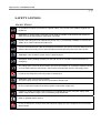
1
FS4104-AW Installation Guide FS4104-AW – Installation Guide 2 / 31 FS4104-AW VDSL Termination Processing Unit INSTALLATION GUIDE Rev. 1 DATE: June 2005 Rights CopyRight 2004 Aethra SpA All Rights Reserved Printed in Italy Trademarks AETHRA is registered trademark of Aethra SpA. Ethernet is registered trademark of Xerox Corporation. Microsoft and Windows are registered trademarks of Microsoft Corporation. FS4104-AW – Installation Guide 3 / 31 INDEX SAFETY ADVISES ...............................................................................................................................................5 Safety Rules ........................................................................................................................................................5 Environmental ward ............................................................................................................................................6 Warnings .............................................................................................................................................................7 Cleaning ..............................................................................................................................................................7 CE Marking.........................................................................................................................................................7 FCC15 Class B COMPLIANCE .........................................................................................................................7 Introduction ...........................................................................................................................................................8 Users....................................................................................................................................................................8 Contents ..............................................................................................................................................................8 Installation .............................................................................................................................................................9 Package ...............................................................................................................................................................9 Mounting ...........................................................................................................................................................10 Connections.......................................................................................................................................................10 Powering up ..................................................................................................................................................10 Description ...........................................................................................................................................................11 Characteristics ...................................................................................................................................................11 Front panel ........................................................................................................................................................12 Back panel.........................................................................................................................................................13 Operating connections.........................................................................................................................................14 Local network....................................................................................................................................................14 Wireless LAN....................................................................................................................................................15 VDSL line .........................................................................................................................................................16 Connection to CONSOLE port.............................................................................................................................17 Configuration.......................................................................................................................................................18 General information ..........................................................................................................................................18 Connection to Internet.......................................................................................................................................18 FS4104-AW – Installation Guide 4 / 31 Preliminary operations for the use of the internal WEB server ....................................................................19 Internal WEB server configuration with “Quick Start” ................................................................................20 System passwords .............................................................................................................................................22 How to change the IP address ...........................................................................................................................23 Changing the IP address from WEB.............................................................................................................23 StarManager ........................................................................................................................................................24 How to connect the device ................................................................................................................................24 LAN and DHCP server configuration...............................................................................................................25 WAN configuration...........................................................................................................................................25 Password ...........................................................................................................................................................26 Configuration parameters..................................................................................................................................27 File Download...................................................................................................................................................27 File Upload........................................................................................................................................................28 APPENDIX “A” – FS4104-AW features ...........................................................................................................29 Technical Specifications ...................................................................................................................................29 Interfaces.......................................................................................................................................................29 Power Supply................................................................................................................................................29 Dimensions ...................................................................................................................................................29 Compatible Standards ...................................................................................................................................29 Supported Protocols......................................................................................................................................29 Supported Network Services ........................................................................................................................30 VDSL............................................................................................................................................................30 ATM .............................................................................................................................................................30 Storage and operating conditions ......................................................................................................................31 Reference regulations........................................................................................................................................31 FS4104-AW – Installation Guide 5 / 31 SAFETY ADVISES SAFETY RULES To guarantee continuous protection for operator safety, only use the mains adapter supplied with the device. WARNING: for power supply connection use an easily accessible outlet located near the device. Never remove the mains plug for permanent connection. Connect the LAN port to an internal LAN circuit only. It is absolutely forbidden to connect the system to an outdoor telecommunication line. Connect the measurement cable of the telephone interface to the device connector and then to the outdoor telecommunication line to avoid accidental contacts with live parts of the TNV circuits. WARNING: never install the system during a lightning storm. WARNING: When installing the device on the wall, do not fix it so that it can be removed in an emergency. The change from cold to hot environments can cause the formation of condensate inside the device. To avoid malfunctioning, wait at least 1 hour before connecting the device to the supply mains. In case of fire, absolutely avoid using water to extinguish it. WARNING: RISK OF ELECTRIC SHOCK The power supply used by this device involves lethal voltage levels. Do not access internal parts of the device (and/or of the power supply unit). If objects or liquids penetrate inside the device, immediately disconnect the power supply cable. Before using the device again, have it checked by specialized staff. Refer to qualified staff for service. In case of intervention, always check that the power supply has been completely and successfully disconnected. FS4104-AW – Installation Guide 6 / 31 ENVIRONMENTAL WARD The equipment that you bought has required the extraction and use of natural resources for its production. It may content hazardous substances for the health and the environment. In order to avoid the dissemination of those substances in our environment and to diminish the pressure on the natural resources, we encourage you to use the appropriate take-back systems. Those systems will reuse or recycle most of the materials of your end life equipment in a sound way. The crossed-bin symbol invites you to use those systems. If you need more information on the collection, reuse and recycling systems, please contact your local or regional waste administration. You can also contact us for more information on the environmental performances of our products. La production de l'équipement que vous avez acheté a nécessité l'extraction et l'utilisation de ressources naturelles. Il peut contenir des substances dangereuses pour la santé et l'environnement. Afin d'éviter la diffusion de ces substances dans notre environnement et de réduire l'exploitation des ressources naturelles, nous vous encourageons à utiliser les systèmes de récupération appropriés. Ces systèmes réutiliseront ou recycleront de manière saine la plupart des composants de votre équipement périmé. Le symbole d'une poubelle barrée vous invite à utiliser ces systèmes. Si vous désirez plus d'informations sur les systèmes de ramassage, de réutilisation et de recyclage, veuillez prendre contact avec votre administration locale ou régionale chargée de l'évacuation des déchets. Vous pouvez également nous contacter pour plus d'informations sur les effets de nos produits sur l'environnement. Voor het produceren van de apparatuur die u hebt aangekocht, werden natuurlijke hulpbronnen aangeboord en benut. Deze apparatuur kan stoffen bevatten die gevaarlijk zijn voor de gezondheid en het milieu. Om te verhinderen dat deze stoffen in ons milieu terechtkomen en om tevens verspilling van de natuurlijke hulpbronnen tegen te gaan, verzoeken wij u de geschikte inleverings- en inzamelingssystemen te benutten. Die systemen zullen de meeste materialen waaruit uw opgebruikte apparatuur bestaat op afdoende wijze hergebruiken of recycleren. Het symbool met de doorkruiste vuilnisbak verzoekt u dergelijke systemen te gebruiken. Als u meer informatie wenst over de inzamelings-, hergebruiks- en recycleringssystemen, gelieve contact op te nemen met uw gemeentelijke of regionale dienst voor afvalverwerking. U kan ons ook altijd contacteren als u meer informatie wenst over de invloed van onze producten op het milieu. Die Herstellung der Ausrüstung, die Sie gekauft haben, hat die Gewinnung und den Gebrauch von Naturresourcen benötigt. Sie kann für die Gesundheit und die Umwelt gefährliche Substanzen enthalten. Um die Verbreitung jener Substanzen in unsere Umwelt zu verhindern und die Ausnutzung der Naturresourcen zu verringern, ermutigen wir Sie dazu, die passenden Rückgewinnungssysteme zu benutzen. Diese Systeme werden die meisten Komponenten Ihrer rückständigen Ausrüstung auf gesunde Weise wiederverwenden oder wiederverwerten. Das Symbol des durchgestrichenen Mülleimers fordert Sie dazu auf, jene Systeme zu benutzen. Wenn Sie weitere Informationen über die Sammlungs-, Wiederverwendungs- und Wiederverwertungs-systeme möchten, kontaktieren Sie bitte die örtliche oder regionale Verwaltung, die für die Entsorgung der Abfälle zuständig ist. Für weitere Informationen über die Auswirkungen unserer Produkte auf die Umwelt können Sie uns ebenfalls kontaktieren. FS4104-AW – Installation Guide 7 / 31 WARNINGS CAUTION: Many of the components used in this device are sensitive to electrostatic charge. In case of manipulation of the connection cables, disconnect the power supply and avoid direct contacts with the connector terminals. When handling electronic components, to eliminate any static electricity touch a grounded surface. If possible, wear a grounding arm band. Failure to comply with these warnings could cause permanent damage to device. CLEANING To clean the device use a soft cloth either dry or moistened with a little detergent. Never use any type of solvents, such as alcohol or gasoline, to avoid damaging the finish. CE MARKING Hereby, Aethra S.p.A. declares that this product complies with requirements of the EMC Directive 89/336/EC and Low Voltage Directive 73/23/EC, as amended by Directives 92/31/EC and 93/68/EC, and (where applicable) with essential requirements and other relevant notes of the R&TTE Directive 1999/5/EC. The declaration of conformity maybe obtained from: Aethra S.p.A. - Via Matteo Ricci, 10 - 60020 Ancona - Italy www.aethra.com - [email protected] FCC15 CLASS B COMPLIANCE This equipment has been tested and found to comply with the limits for a Class B digital device, pursuant to part 15 of the FCC rules. These limits are designed to provide reasonable protection against harmful interference in a residential installation. This equipment generates, uses and can radiate radio frequency energy and, if not installed and used in accordance with the instructions, may cause harmful interference to radio communications. However, there is no guarantee that interference will not occur in a particular installation. If this equipment does cause harmful interference to radio or television reception, which can be determined by turning the equipment off and on, the user is encouraged to try to correct the interference by one or more of the following measures: - reorient or relocate the receiving antenna - increase the separation between the equipment and the receiver - connect the equipment into an outlet on a circuit different from that to which the receiver is connected - consult the dealer or an experienced radio/TV technician for help FS4104-AW – Installation Guide 8 / 31 Introduction Welcome to the high speed world. With FS4104-AW you can connect your local network (LAN) to remote networks (WAN) and navigate on Internet over a dedicated high-speed data channel obtaining very good performances. The FS4104-AW implements the Full Service Access Network model associating an ATM VCC to each service, such as: Fast Internet connection with routed and/or bridged traffic Broadcast TV Video On Demand Voice/Videoconferencing over IP THE GENERIC NOTATION VDSL USED IN THIS GUIDE IS FOR VDSL in reference to the router FS4104-AW; Detailed configurations are illustrated in the “ATOS – User’s Guide” contained in the installation CD supplied with the device. READ THIS DOCUMENT CAREFULLY BEFORE USE TO AVOID INCORRECT INSTALLATION. Users This Guide is addressed to users and network administrators, hardware and software technicians of Ethernet local networks or individual PC stations. Contents Introduction. Installation: it describes the package contents and provides information on interface connections. Description : it describes technical characteristics, front and back panel. Operating connections: it describes connections for LAN, Wireless LAN, WAN and console command transmission. Configuration: it describes minimum configuration for quick network access. StarManager: it describes the quick installation application functions. APPENDIX “A” – FS4104-AW features: it describes FS4104-AW technical specifications. FS4104-AW – Installation Guide 9 / 31 Installation Installation is simple and quick. For easier installation please follow the sequence of operations illustrated in this Guide. Package Remove FS4104-AW and accessories from the package. Check that the contents complies with the list of materials described in this Guide. The following components are contained in the package: FS4104-AW; connection kit; power supply; a CD containig FS4104-AW and ATOS Guides and the application StarManager. FS4104-AW – Installation Guide 10 / 31 Mounting FS4104-AW can be placed on a horizontal surface or hung to the wall. Make sure that the device is easily accessible and placed near an electrical outlet that complies with current regulations. The device must be placed in a dry place with good ventilation. Never place the device in closed places without ventilation. Connections There are three types of connections: Power supply connection Operating connections (see § Operating connections): - LAN (local network), Wireless LAN and VDSL (WAN) traffic; - console interface communication. Powering up Connect the power supply to the “PWR” (power) connector and to an compatible electrical outlet. Never cut power cables for direct connection to electrical mains. ON OFF PWR 1 2 FS4104-AW – Installation Guide 11 / 31 Description FS4104-AW is an VDSL (Very high speed Digital Subscriber Line) router with switch Ethernet 10/100BaseT ports and an Ethernet wireless AP1. It can be used to connect PC’s, printers or any other device with Ethernet network board to Internet or other remote networks (WAN). Characteristics VDSL DMT based technology; ATM (Asynchronous Transfer Mode) transportation: it supports up to 10 virtual circuits (VC) for data transmission; embedded integrated 4-port 10/100BaseT autosensitive Ethernet switch interface with direct access from back panel for quick connection of network devices; embedded 802.11b/g access point; simple configuration procedures for immediate device connection to network; WEB-Browser guided configuration from any PC in the LAN; Network Address Translation (NAT) functionality to share the same IP address between different stations in the LAN and provide suitable security system for connections; Dynamic Host Configuration Protocol (DHCP) server functionality for automatic configuration of PC’s connected to FS4104-AW in the LAN and DHCP client LAN side; DNS (Domain Name System) server and forwarder functionality for host and domain name resolution in IP addresses; firewall function for internal network protection against external attacks and personalized management of access rights of individual hosts to network services; band monitoring of outgoing WAN traffic; QoS (layer 3 and layer 2) functionalities for voice and data traffic management optimization; VPN (Virtual Private Network) with the following tunneling modes: IP-SEC, GRE, IpinIP, PPTP server/client; IPSEC protocol to increase security either for VPN or end-to-end connection over a public infrastructure such as the Internet VLANs (Virtual LANs) with the following configuration: Port based (Untagget to tagged), “Implicit” VLAN operation (port-to-VCC mapping), Trunking (VLID-to-VCC forwarding), Priority based queuing. 1 Access Point. FS4104-AW – Installation Guide 12 / 31 1 2 3 4 LINE 1 2 3 4 PWR FS 4104-AW LAN WIRELESS INTERNET LINE Front panel FS4104-AW The front panel houses 7 LED’s that provide information on operation mode: LED status LED LED function color LINE GREEN Correct connection with public During establishment of exchange modem. physical level GREEN IP connected (the device has IP connected and IP traffic a WAN IP address from is passing thru the device IPCP or DHCP and DSL is (either direction) 2 up) and no traffic detected. INTERNET OFF Device in Bridged mode or no xDSL connection ON FLASHING Device attempted to become IP connected and failed3 RED WIRELESS GREEN WIRELESS interface not active WLAN features activated WLAN activity present (traffic in either direction) LAN 1, 2, 3, 4 GREEN No device connected to the associated port Powered device connected to the associated port LAN activity present (traffic in either direction). Power supply. GREEN PWR No power supply RED (Successful initialization) Initialization. Power supply. (malfunctioning) 2 If the IP or PPPoE session is dropped, the light will remain green if an ADSL connection is still present. The light will turn red when it attempts to reconnect and DHCP or PPPoE and fails 3 No DHCP response, no PPPoE response, PPPoE authentication failed, no IP address from IPCP, etc. FS4104-AW – Installation Guide 13 / 31 Back panel The back panel houses: ON OFF PWR 1 2 LAN 3 4 CONSOLE LINE FS4104-AW N° 1 switch to turn on/off power supply; N°. 1 PWR port to connect the power supply adapter; N°. 4-port 10/100 BaseT autosensitive Ethernet switch interface with RJ-45 connector; N°. 1 CONSOLE port for programming through terminal or PC serial port with MiniDIN 8P connector; N°. 1 LINE port for VDSL (WAN) connection with RJ-11 (6p/2c) connector. FS4104-AW – Installation Guide 14 / 31 Operating connections Local network You can connect up to 4 PC’s or other devices with Ethernet 10/100BaseT interface to the Ethernet RJ-45 ports with braid cables ending with RJ–45 connectors. An external device (hub or switch) is needed to connect other PC to FS4104-AW. HUB (not included) The following example illustrates how to connect RJ45 connectors to CAT5 cables for LAN. Follow the color sequence to obtain correct signal screening and avoid connection errors. Connectors are seen from the front (wires on the back). 8 – brown 7 – white brown 6 – green 5 – white blue 4 – blue 3 – white green 2 – orange 1 – white orange Wires 1-2 must belong to the same braid; wires 3-6 must belong to a different braid. FS4104-AW – Installation Guide 15 / 31 Wireless LAN Wireless LAN technology (WLAN, IEEE 802.11 standard) is used to realize an inexpensive and scalable local area network that uses high-frequency radio waves rather than wires. Pratically, an Ethernet card is replaced by a Wireless card, a RJ45 port is replaced by an antenna. ATOS4, starting from 2.9 version, can be configured as an AP5 , implements IEEE 802.11b (1999) and IEEE 802.11g (2003) standards. Both 802.11b and 802.11g standards use the DSSS6 modulation, a transmission technology where each bit is trasmitted as a redundant sequence of bits (called chip). From 802.11, 802.11b and 802.11g standars inherit AP access and authentication methods and data cryptography with WEP7. Like traditional networks, the maximum number of contemporary customers a single AP can support depends on amount and type of data to transfer. FS4104-AW has two antennas to improve the radio communication quality, especially into building and in presence of obstacles (Antenna diversity mode). For WLAN configuration refer to ATOS guide (see § “Wireless LAN” and “DHCP” ). Standard 802.11b 802.11g Max Frequency Modulation connection Speed rate (Mbps) coverage 2.4GHz DSSS 100m 1, 2, 5.5, 11 1, 2, 5.5, 11; 6, 9, 12, 18, 2.4GHz DSSS 100m 24, 36, 48, 54 # max contemporary channels without interference 3 3 BB Network WIRELESS VDSL Wireless device AP 4 In Aethra devices with wireless card. Access Point. 6 Direct Sequence Spread Spectrum. 7 Wired Equivalent Privacy, protocol that uses the RC4 cypher algorithm for security and the CRC-32 for data integrity check. 5 FS4104-AW – Installation Guide 16 / 31 VDSL line The VDSL connection is made by connecting the line cable provided with the device to the LINE port and to a telephone socket. If the telephone system is connected to a PABX or device that is especially sensitive to VDSL signal, ask your ISP to install a VDSL splitter. The VDSL splitter is inserted at the beginning of the line to separate the traditional telephone signal from VDSL signal, thus avoiding mutual interference between the two services. Public exchange ON OFF PWR 1 2 LAN 3 4 CONSOLE LINE VDSL Splitter FS4104-AW – Installation Guide 17 / 31 Connection to CONSOLE port Use the adapter supplied with FS4104-AW to connect a PC or any other system capable of emulating a ‘start-stop’ terminal: ON OFF PWR 1 2 LAN 3 4 CONSOLE LINE FS4104-AW – Installation Guide 18 / 31 Configuration General information Once you have made the connections illustrated in chapter 0, choose the configuration mode from the ones illustrated below. To configure FS4104-AW: if no PC with LAN board is available, you can use the console port and StarManager (software included in the installation CD), as illustrated in § StarManager; if a PC with LAN board is available, you can connect it to one of FS4104-AW Ethernet ports and carry out the WEB browser configuration as illustrated in § Internal WEB server configuration with “Quick Start”. If you connect FS4104-AW to an existing LAN you probably have to change the address assigned by default to FS4104-AW (10.0.0.1) to make it compatible with subnet addresses used in the LAN. In this case, after the initial configuration, continue as illustrated in § How to change the IP address and connect the device to the LAN. Less expert users can use the Command Line Interface (CLI) configuration through serial connection and terminal emulation software8 or Telnet session, as illustrated in “ATOS User’s Guide”. Connection to Internet For quick connection to Internet with FS4104-AW, get the following information from your Internet Service Provider and follow the instructions below. The following information is needed: VCI and VPI value; encapsulation type used by ISP: PPPoA (PPP over ATM), PPPoE (PPP over Ethernet) or RFC1483 (IP over ATM); User name and Password (in case of PPP encapsulation). 8 such as Windows HyperTerminal. FS4104-AW – Installation Guide 19 / 31 Preliminary operations for the use of the internal WEB server Connect a PC with LAN interface to one of FS4104-AW Ethernet ports. In the “Properties” option of the local network connection set the TCP/IP parameters as illustrated below for the different Microsoft operating sytems: Windows 98 Windows 2000 Windows NT FS4104-AW – Installation Guide 20 / 31 Internal WEB server configuration with “Quick Start” By using the DHCP services for the automatic configuration of network parameters in the LAN PC’s, you can open the browser and enter the local IP address assigned to (10.0.0.1 by default). The initial page refers to authentication (login). The password field is empty by default. Enter the user name9 (maximum 10 characters) and confirm. Open the WEB Browser; enter the address 10.0.0.1 or simply “ATOS“; enter User Name and Password (leave the password field empty if you did not change the password). After login, select the language in the vertical frame on the left; select “Quick Start” to start the guided procedure and enter ISP parameters. 9 You must enter at least one alphanumeric value in the user name field. For example, use the operator’s last name for easier logon identification. FS4104-AW – Installation Guide 21 / 31 Enter encapsulation type and LLC SNAP mode and click Next; different parameters must be entered based on encapsulation type (PPP, RFC1483, etc.). Enter the VPI (Virtual Path Identifier) and VCI (Virtual Channel Identifier) parameters for WAN1 (interface enabled by default). This information can be found in the contract. If you select RFC1483 encapsulation you must enter WAN-side IP address, netmask and remote IP address (Provider-side). If you select PPPoA or PPPoE encapsulation you must enter User Name and Password assigned by the ISP. FS4104-AW – Installation Guide 22 / 31 Now you have entered all configuration parameters. Save the new configuration. Reboot the device after saving. The new configuration will be loaded. Enjoy navigation! System passwords Two user levels are available: Administrator (Admin); User. To discrimante the level you must configure two different passwords for the two users. This operation can be accessed from StarManager (see 0) or from the internal WEB server System page as illustrated below: Click “System” on the left of the WEB page; select “Password” in the System page; enter the old administrator and/or user password in the new page and click “Send”. FS4104-AW – Installation Guide 23 / 31 Now enter the new administrator or user password and click “Send”. A message confirms that the operation was successful. How to change the IP address After you set the configuration parameters and before you connect FS4104-AW to an existing LAN, check that the default IP address (10.0.0.1) is compatible with the addresses used in the LAN. You can change the address with WEB server or StarManager (see § LAN and DHCP server configuration). Changing the IP address from WEB Enter IP address and net mask in the LAN0 page; confirm with “Send” and save. FS4104-AW – Installation Guide 24 / 31 StarManager StarManager is a simple installation application10 that uses FS4104-AW console port to communicate with it. It is contained in the installation CD supplied with the device. Follow the instructions given in 0 to connect your PC to FS4104-AW console port. The initial page is shown below. Quick Configuration : it starts the quick configuration procedure for LAN and Internet connection. File Download : it transfers configuration files or firmware upgrades from your PC to the device. Configuration File Upload : it saves the current device configuration into a PC file. How to connect the device Turn off the device; connect the console port to the COM port in your PC; select the COM port used to connect FS4104-AW; turn on the device and click Next. The Current Status: item shows the type of connected device (after you select the COM port and turn on the device). 10 For Windows. FS4104-AW – Installation Guide 25 / 31 LAN and DHCP server configuration Enter IP address and subnet mask; check the box to use the DHCP server. A new window appears (see below). Enter the start and stop IP address. WAN configuration This section is used to enter the ISP service parameters; select the encapsulation mode from the pull-down menu as shown below: FS4104-AW – Installation Guide 26 / 31 If you select PPP encapsulation, you must enter the parameters shown here on the left; if you select RFC1483 encapsulation, you must enter the parameters shown here on the left. Password You can enter a password to protect the new configuration. FS4104-AW – Installation Guide 27 / 31 Configuration parameters Configuration parameters are shown in this page at the end of the configuration procedure. File Download You can transfer a configuration file or firmware upgrade from the PC to the device. Select this button to open the window used to select the file you want to transfer. FS4104-AW – Installation Guide 28 / 31 File Upload You can transfer a configuration file (saved with Save in the device) from the device to the PC. Select this button to transfer the configuration file from the device to the PC. FS4104-AW – Installation Guide 29 / 31 APPENDIX “A” – FS4104-AW features Technical Specifications Interfaces 4 Ethernet 10/100BaseT (RJ-45 100 ohm) 1 VDSL 1 RS232 230Kbps (9600 bps serial interface for programming from CLI) Power Supply External power supply unit: OUT1: 12V – 0.8A INPUT: 100 − 240 VAC, 50 – 60 Hz Dimensions Length 281 mm, width 168 mm, height 34 mm. Weight 450 gr Compatible Standards VDSL: ETSI TS 101 270-1 (2003), ETSI TS 270-2 (2003), ANSI T1E11.4 VDSL Part3 and Part 4, ITU G.993.1 ATM: ITU-T I.361, ITU-T I.363.5, ITU-T I.432, ITU-T I.610, ILMI, af-ilmi-0065.000 WLAN: IEEE 802.11b, IEEE 802.11g Supported Protocols TCP, UDP, ICMP, IP, IGMP RIP V1, V2, V1 compatibile PAP CHAP-MD5, MS-CHAP, PPTP, IPSEC DHCP, DNS, HTTP, TELNET, SNMP, Multicast, Broadcast. FS4104-AW – Installation Guide 30 / 31 Supported Network Services IP over ATM (RFC 2684 ex 1483) PPP over ATM (RFC 2364) PPP over Ethernet (RFC 2516) LLC/SNAP o VC-Mux encapsulation VLANs (802.1Q and 802.1p) VDSL Full rate VDSL over POTS ATM 10 VC (VCs) channels Any Class of Service is covered: UBR, UBR+, VBR-rt, VBR-nrt, CBR Selective Cell Loss Priority field marking on the basis of either the DSCP value of upper layer IP packets or 802.1p value of Ethernet frames ILMI for ATM VCC configuration (VPI/VCI, CoS parameters) from the remote CO Adaptation: AAL5 FS4104-AW – Installation Guide 31 / 31 Storage and operating conditions OPERATING TEMPERATURE -5°C ÷ +45 °C RELATIVE OPERATING HUMIDITY 10% ÷ 93 % (without condensation) STORAGE TEMPERATURE -40 ÷ +70 °C Reference regulations (CE MARKING AND RELIABILITY TESTS) STORAGE TRANSPORTATION OPERATING CONDITIONS EMC PROTECTIONS SAFETY CEI 50-3 EN 60068-2-1 Test Ab (IEC 60068-2-1) EN 60068-2-2 Test Bb (IEC 60068-2-2) IEC 60068-2-14 Test Nb IEC 60068-2-18 IEC 60068-2-30 Test Db - Variant 1 IEC 60068-2-27 Test Ea IEC 60068-2-64 Test Fdb (CEI 50-6/9) ETSI EN 300 019-2-1 T 1.3 CEI 50-3 EN 60068-2-1 Test Ab (IEC 60068-2-1) EN 60068-2-2 Test Bb (IEC 60068-2-2) IEC 60068-2-14 Test Nb IEC 60068-2-18 IEC 60068-2-30 Test Db - Variant 1 IEC 60068-2-29 Test Eb IEC 60068-2-32 Test Ed - Method 1 IEC 60068-2-64 Test Fdb (CEI 50-6/9) ETSI EN 300 019-2-2 T 2.3 CEI 50-3 EN 60068-2-1 Test Ab (IEC 60068-2-1) EN 60068-2-2 Test Bb (IEC 60068-2-2) IEC 60068-2-14 Test Nb IEC 60068-2-18 IEC 60068-2-30 Test Db - Variant 1 IEC 60068-2-56 Test Cb IEC 60068-2-27 Test Ea IEC 60068-2-31 Test Ec IEC 60068-2-64 Test Fdb (CEI 50-6/9) ETSI EN 300 019-2-3 T 3.2 EN 55022 EN 55024 EN 61000-3-2 EN 61000-3-3 FCC15 ITU-T-K.20 ITU-T-K.21 EN 60950-1 (IEC 60950-1)