1
USER’S MANUAL
FX2N-1RM-E-SET PROGRAMMABLE CAM SWITCH
FX2N-1RM-E-SET Programmable Cam Switch
Foreword
• This manual contains text, diagrams and explanations which will guide the reader in the
correct installation and operation of the Programmable Cam Switch FX2N-1RM-E-SET. It
should be read and understood before attempting to install or use the unit.
• For handling of the FX2N/FX2NC Series PLC main unit and FX2N Series extension blocks as
well as details of instructions, refer to the corresponding Hardware manuals and
programming manuals offered separately.
• If in doubt at any stage of the installation of Programmable Cam Switch FX2N-1RM-E-SET
always consult a professional electrical engineer who is qualified and trained to the local
and national standards that applies to the installation site.
• If in doubt about the operation or use of Programmable Cam Switch FX2N-1RM-E-SET
please consult the nearest Mitsubishi Electric distributor.
• This manual is subject to change without notice.
FX2N-1RM-E-SET Programmable Cam Switch
Programmable Cam Switch
FX2N-1RM-E-SET
USER’S MANUAL
Manual number
: JY992D71101
Manual revision
: K
Date
: December 2011
This manual confers no industrial property rights or any rights of any other kind, nor does it confer any patent
licenses. Mitsubishi Electric Corporation cannot be held responsible for any problems involving industrial
property rights which may occur as a result of using the contents noted in this manual.
i
FX2N-1RM-E-SET Programmable Cam Switch
MS,MS-DOS and Windows are registered trademarks of Microsoft Corporation.
IBM and AT are registered trademarks of International Business Machines Corporation.
All other brand and product names are trademarks or registered trademarks of
theirrespective owners.
ii
FX2N-1RM-E-SET Programmable Cam Switch
FAX BACK
Mitsubishi has a world wide reputation for its efforts in continually developing and pushing back
the frontiers of industrial automation. What is sometimes overlooked by the user is the care and
attention to detail that is taken with the documentation. However, to continue this process of
improvement, the comments of the Mitsubishi users are always welcomed. This page has been
designed for you, the reader, to fill in your comments and fax them back to us. We look forward to
hearing from you.
Fax numbers:
Your name: ..................................................
Mitsubishi Electric....
....................................................................
America
(01) 847-478-2253
Your company:.............................................
Australia
(02) 638-7072
....................................................................
Germany
(0 21 02) 4 86-1 12
Your location:...............................................
Spain
(34) 93-589-1579
....................................................................
United Kingdom
(01707) 278-695
Please tick the box of your choice
What condition did the manual arrive in?
Good
Minor damage
Will you be using a folder to store the manual?
Yes
No
What do you think to the manual presentation?
Tidy
Unfriendly
Are the explanations understandable?
Yes
Not too bad
Unusable
Unusable
Which explanation was most difficult to understand: .................................................................
...................................................................................................................................................
Are there any diagrams which are not clear?
Yes
No
If so,which: .................................................................................................................................
What do you think to the manual layout?
Good
Not too bad
Unhelpful
If there one thing you would like to see improved, what is it? ....................................................
...................................................................................................................................................
...................................................................................................................................................
Could you find the information you required easily using the index and/or the contents, if possible
please identify your experience:.................................................................................................
...................................................................................................................................................
...................................................................................................................................................
...................................................................................................................................................
...................................................................................................................................................
Do you have any comments in general about the Mitsubishi manuals? ....................................
...................................................................................................................................................
...................................................................................................................................................
...................................................................................................................................................
...................................................................................................................................................
Thank you for taking the time to fill out this questionnaire. We hope you found both the product
and this manual easy to use.
iii
FX2N-1RM-E-SET Programmable Cam Switch
iv
FX2N-1RM-E-SET Programmable Cam Switch
Guidelines for the safety of the user and protection of the Programmable Cam
Switch FX2N-1RM-E-SET
This manual provides information for the use of the programmable cam switch FX2N-1RM-E-SET.
The manual has been written to be used by trained and competent personnel. The definition of
such a person or persons is as follows;
a) Any engineer who is responsible for the planning, design and construction of automatic
equipment using the product associated with this manual should be of a competent nature,
trained and qualified to the local and national standards required to fulfill that role. These
engineers should be fully aware of all aspects of safety with regards to automated
equipment.
b) Any commissioning or service engineer must be of a competent nature, trained and
qualified to the local and national standards required to fulfill that job. These engineers
should also be trained in the use and maintenance of the completed product. This includes
being completely familiar with all associated documentation for the said product. All
maintenance should be carried out in accordance with established safety practices.
c) All operators of the completed equipment (see Note) should be trained to use this product
in a safe manner in compliance to established safety practices. The operators should also
be familiar with documentation which is associated with the operation of the completed
equipment.
Note : Note: the term ‘completed equipment’ refers to a third party constructed device which
contains or uses the product associated with this manual.
Notes on the Symbols Used in this Manual
At various times throughout this manual certain symbols will be used to highlight points of
information which are intended to ensure the users personal safety and protect the integrity of
equipment. Whenever any of the following symbols are encountered its associated note must be
read and understood. Each of the symbols used will now be listed with a brief description of its
meaning.
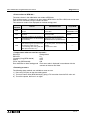
Hardware Warnings
1) Indicates that the identified danger WILL cause physical and property damage.
2) Indicates that the identified danger could POSSIBLY cause physical and property
damage.
3) Indicates a point of further interest or further explanation.
Software Warnings
4) Indicates special care must be taken when using this element of software.
5) Indicates a special point which the user of the associate software element should be
aware of.
6) Indicates a point of interest or further explanation.
v
FX2N-1RM-E-SET Programmable Cam Switch
• Under no circumstances will Mitsubishi Electric be liable responsible for any consequential
damage that may arise as a result of the installation or use of this equipment.
• All examples and diagrams shown in this manual are intended only as an aid to understanding
the text, not to guarantee operation. Mitsubishi Electric will accept no responsibility for actual
use of the product based on these illustrative examples.
• Please contact a Mitsubishi Electric distributor for more information concerning applications in
life critical situations or high reliability.
vi
FX2N-1RM-E-SET Programmable Cam Switch
Contents
1. Introduction ......................................................................................... 1-1
1.1 Outline of the product ........................................................................................ 1-1
1.2 Features ............................................................................................................ 1-1
1.3 Product configuration ........................................................................................ 1-3
1.4 Outside dimensions and name of each part ..................................................... 1-3
1.5 System configuration ......................................................................................... 1-5
1.5.1 Connecting the FX2N-1RM to PLC ..................................................................................... 1-5
1.5.2 Using the FX2N-1RM individually ....................................................................................... 1-7
1.5.3 CC-Link connection .............................................................................................................. 1-8
1.5.4 Resolver and connection cable .......................................................................................... 1-10
1.5.5 Connecting the peripheral equipment ................................................................................ 1-11
1.5.6 Cautions on use of a personal computer and the FX-20P-E ............................................. 1-14
2. Installation ........................................................................................... 2-1
2.1 Installation method ............................................................................................ 2-1
2.2 Wiring ................................................................................................................ 2-1
2.3 Installing the resolver ........................................................................................ 2-2
3. Specifications ...................................................................................... 3-1
3.1 General specifications ...................................................................................... 3-2
3.2 Performance specifications .............................................................................. 3-3
3.3 Resolver specifications .................................................................................... 3-3
3.4 Power supply specifications ............................................................................. 3-4
3.5 Input specifications ........................................................................................... 3-4
4. External Wiring .................................................................................... 4-1
4.1 Wiring of the power supply and the input .......................................................... 4-2
5. Extension Block Specifications and External Wiring ........................... 5-1
5.1 Extension block specifications (transistor output type) .................................... 5-1
5.2 Output wiring (transistor output type) ............................................................... 5-1
6. Basic Setting ....................................................................................... 6-1
6.1 Handling of the RUN and PRG modes .............................................................. 6-2
6.2 Specifying the bank ........................................................................................... 6-3
6.3 Automatic angle advance function .................................................................... 6-4
6.4 Individual automatic angle advance function .................................................... 6-6
6.5 Setting the reference angle ............................................................................... 6-9
6.6 Handling the keyword ...................................................................................... 6-10
6.7 Current angle transfer function ........................................................................ 6-11
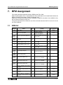
7. BFM Assignment ................................................................................. 7-1
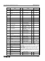
7.1 BFM list ............................................................................................................ 7-1
7.2 Description on BFM ........................................................................................... 7-4
7.3 Cautions on creation of a sequence program ................................................. 7-11
7.4 Program example ............................................................................................ 7-12
7.4.1 Program example which uses FROM/TO instruction ......................................................... 7-12
7.4.2 Program example which uses indirect specification (BFM #100 to #105) ......................... 7-14
vii
FX2N-1RM-E-SET Programmable Cam Switch
Contents
8. Program Operating Procedures .......................................................... 8-1
8.1 Functions offered by the data setting panel ...................................................... 8-1
8.2 Basic operating procedures .............................................................................. 8-3
8.2.1 Common items ..................................................................................................................... 8-3
8.2.2 Read .................................................................................................................................... 8-3
8.2.3 Write and modification.......................................................................................................... 8-4
8.2.4 Insertion ............................................................................................................................... 8-5
8.2.5 Deletion ................................................................................................................................ 8-6
8.2.6 Copy..................................................................................................................................... 8-8
8.2.7 Write and modification of teaching ....................................................................................... 8-9
8.2.8 Insertion of teaching........................................................................................................... 8-10
8.2.9 Changing over the mode between RUN and PRG ............................................................ 8-11
8.2.10 Reading/setting the reference angle ................................................................................ 8-12
8.3 Application operating procedures ................................................................... 8-13
8.3.1 Specifying the resolution [FNC0]........................................................................................
8.3.2 Specifying the rotation direction of the resolver [FNC1]....................................................
8.3.3 Write-protect function of the EEPROM [FNC2] ..................................................................
8.3.4 Bank specification method [FNC3].....................................................................................
8.3.5 Setting the automatic angle advance function [FNC4, 13 to 26] ........................................
8.3.6 Individual automatic angle advance function [FNC5,90] ...................................................
8.3.7 Prohibition of RUN to PRG operation [FNC6] ...................................................................
8.3.8 Current angle transfer function [FNC7] ..............................................................................
8.3.9 Inverting the output pattern [FNC50]..................................................................................
8.3.10 Batch addition/subtraction of the output set angle [FNC60, 61].......................................
8.3.11 Batch addition/subtraction of the ON output set angle[FNC62, 63] .................................
8.3.12 Batch addition/subtraction of the OFF output set angle [FNC64, 65]................................
8.3.13 Outputting the BCD current angle [FNC70, 71]................................................................
8.3.14 Outputting the pulse string [FNC72, 73]...........................................................................
8.3.15 RUN output [FNC74] ........................................................................................................
8.3.16 Outputting the one-phase pulse string [FNC75]...............................................................
8.3.17 Confirming and deleting the setting..................................................................................
8.3.18 Prohibiting write to the EEPROM and preventing theft of a program................................
8-13
8-13
8-14
8-14
8-15
8-17
8-21
8-21
8-22
8-23
8-24
8-25
8-26
8-27
8-28
8-28
8-29
8-30
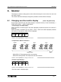
9. Monitor ................................................................................................ 9-1
9.1 Changing over the monitor display ................................................................... 9-1
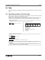
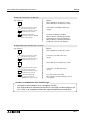
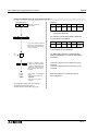
10. Test ................................................................................................. 10-1
10.1 Operating procedure of the test mode .......................................................... 10-1
11. Diagnostics ...................................................................................... 11-1
11.1 Indication and causes of errors ..................................................................... 11-1
Appendix ............................................................................................... A-1
viii
FX2N-1RM-E-SET Programmable Cam Switch
1
Introduction
2
Installation
3
Specifications
4
External Wiring
5
Extension Block Specifications and External Wiring
6
Basic Setting
7
BFM Assignment
8
Program Operating Procedures
9
Monitor
10
Test
11
Diagnostics
Appendix
FX2N-1RM-E-SET Programmable Cam Switch
FX2N-1RM-E-SET Programmable Cam Switch
1.
Introduction 1
Introduction
This section describes the outline of the programmable cam switch FX2N-1RM and introduces
the peripheral equipment.
1.1
Outline of the product
The programmable cam switch FX2N-1RM (hereinafter referred to as FX2N-1RM or unit) detects
the rotation angle of a machine using a brushless resolver, and turns on/off up to 48 points of
transistor outputs at a programmed angle (position).
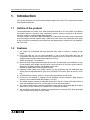
The basic function of the FX2N-1RM is equivalent to a mechanical cam switch shown in the figure
on the next page. However, different from a mechanical cam switch, fine adjustment of the angle
of many cam discs assembled in the mechanism and replacement of switches are not required in
the FX2N-1RM.
1.2
Features
1 ) The angle can be detected with high precision even while a machine is rotating at high
speed.
2 ) One FX2N-1RM unit can be used individually or up to three FX2N-1RM units can be
connected at the end of the system and used as special units of an FX2N/FX3U/FX2NC/FX3UC
programmable controller (hereinafter referred to as PLC).
(Refer to Paragraph 1.5 for details.)
3 ) When transistor output extension blocks for the FX2N are connected, up to 48 points of noncontact outputs are available. Up to 32 points can be turned on at one time. Up to 8 ON/OFF
operations (STEP0 to STEP7) are enabled at each point.
(Maximum speed: 830 r/min during direct output)
4 ) Operation angle setting and monitor display can be performed from the dedicated data
setting panel (integrated add-on type) or by FROM/TO instructions given by the PLC main
unit.
5 ) An EEPROM (no battery) is built in. Up to 8 types of programs can be saved.
6 ) A bank can be switched, a program can be modified, and the automatic angle advance
quantity can be modified while the program is running.
7 ) The ladder support software for personal computers in the PLC and the FX-20P-E (both of
them are compatible with FX2N) can be used to save or transfer programs.
8 ) The cable of the brushless resolver assembled in the machine can be extended up to 100 m
(3937 inch). (A relay cable of 5 m (196.85 inch) is offered as standard.)
9 ) The automatic angle advance function can compensate for the mechanical delay generated
while a machine is rotating at a high speed.
1-1
FX2N-1RM-E-SET Programmable Cam Switch
Introduction 1
< Mechanical cam-operated switch >
48-step cam disc (8 teeth maximum/disc)
48 limit switches (1 switch/disc)
1-2
FX2N-1RM-E-SET Programmable Cam Switch
1.3
Introduction 1
Product configuration
The FX2N-1RM package contains the following components.
•
•
•
•
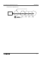
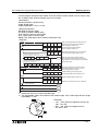
Outside dimensions and name of each part
1)
2)
3)
4)
50(1.97)
21(0.83)
Dimensions: mm (inch)
Weight: approx.0.5kg
5)
8)
30(1.18)
6)
9)
10)
80(3.15)
90(3.54)
111(4.37)
7)
90(3.54)
1.4
Programmable cam-operated switch FX2N-1RM (including data setting panel)
Signal cable FX2N-RS-5CAB
Resolver F2-720RSV
Extension cable to connect PLC (55 mm(2.17 inch))
11)
12)
9(0.35)
16)
15)
97(3.82)
14)
4(0.16)
13)
55(2.17)
When the data setting panel is removed
1)
2)
3)
4)
5)
6)
Mounting hole in 2 positions (2-φ 4.5 (1.77))
Connector to connect resolver
STEP (output pattern) display
BANK (program No.) display
OUT (output No.) display
Operation display LED
RUN: Operation status display
ERR: Error display
ON: ON output setting display (during setting)
OFF: OFF output setting display (during setting)
7 ) DEG (angle) display
8 ) Connector to set personal computer or FX-20P-E
9 ) Connector to connect data setting panel
10) Connector to connect extension block
11) Connector to connect PLC
12) RUN/PRG selector switch
13) Power input/back change-over input terminal
(terminal screw M3)
14) Sixteen keys for operation
15) Hook to attach DIN rail
16) Button to attach data setting panel
1-3
FX2N-1RM-E-SET Programmable Cam Switch
Introduction 1
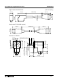
<Signal cable FX2N-RS-5CAB>
50(1.97)
54(2.13)
φ9(0.35)
38(1.50)
5000(196.85)
φ31(1.22)
19(0.75)
[Unit: mm (inch)]
<Relay cable F2-RS-5CAB> (option)
5000(196.85)
54(2.13)
φ31(1.22)
φ28(1.10)
φ9(0.35)
54(2.13)
<Resolver F2-720RSV>
Mounting hole 4-f4.5(0.18)
10(0.39)
45(1.77)
f40(1.57)
45(1.77)
0
-0.015(0.0006)
4.36(0.17)
f10(0.39)
)
97
1.
(
0
f5
0
f33.32(1.31) -0.05(0.002)
45(1.77)
9.5(0.37)
4.36(0.17)
3(0.12)
28(1.10)
4(0.16)
14
(0.55)
9.5(0.37)
60(2.36)
1-4
FX2N-1RM-E-SET Programmable Cam Switch
Introduction 1
1.5
System configuration
1.5.1
Connecting the FX2N-1RM to PLC
FX2N-1RM
PLC FX 2N / FX2NC
FX2N-1RM
FX2N-1RM
X000~X017
BANK
L
COM
24+
N
X1
X2
X3
X4
X7
X10
X13
X14
X15
BANK
OUT
X16
BANK
OUT
RUN
RUN
ERR
IN
0 1 2 3 4 5 6 7
10 11 12 13 14 15 16 17
STEP
DEG
RUN
BATT.V
PROG.E
OUT
Y1
Y2
Y3
Y4
Y5
Y6
0 1 2 3 4 5 6 7
10 11 12 13 14 15 16 17
Y10
Y12
COM3 Y11
Y13
Y14
CPU.E
Y15
BANK
OUT
STEP
FNC
DEL
TEACH
RUN
COPY
ADJ
7
4
1
8
5
2
STOP
0
ERR
STEP
POWER
9
DEG
DEG
ON
ON
OFF
OFF
OFF
ON
OFF
6
BANK
OUT
STEP
FNC
DEL
TEACH
RUN
COPY
ADJ
7
4
1
GO
STOP
0
8
5
2
9
ON
OFF
6
CLR
BANK
OUT
STEP
FNC
DEL
TEACH
RUN
COPY
ADJ
7
4
3
1
GO
OUT 0
1
2
3
4
5
6
7
OUT 0
1
2
3
4
5
6
7
POWER
POWER
ERR
STEP
ON
3
CLR
OUT
Extension block for FX 2N-1RM
(FX2N-16EYT-ESS/UL)
8
5
2
STOP
0
9
⋅⋅⋅⋅⋅
ON
OFF
6
3
CLR
GO
OUT 0
1
2
3
4
5
6
7
OUT 0
1
2
3
4
5
6
7
Y00~Y17 ⋅ ⋅ ⋅ ⋅ ⋅ Y40~Y57
Y000~Y017
48 points maximum
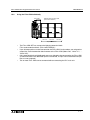
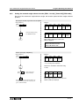
•
•
The FX2N-1RM-SET can connect the following extension block.
FX2N series extension block. (FX2N-16EYT-ESS/UL)
Up to 3 FX2N-1RM units can be connected to the PLC main unit at the end of the system.
The number of blocks that can be connected depends on the PLC main unit and version of
the FX2N-1RM.
Main unit
FX2N
The number which can
be connected
Note
V1.00 (before 1998/2)
1
⎯
V2.00 (from 1998/2)
3
⎯
Version of FX2N-1RM
FX2NC
From the first product
1
FX3U
From the first product
3
V1.00 (before 1998/2)
1
• FX2NC-CNV-IF is
necessary for the
connection.
V2.00 (from 1998/2)
3
• FX0N-30EC and FX0N65EC cannot be used.
FX3UC
•
•
•
• FX2NC-CNV-IF is
necessary for the
connection.
• FX0N-30EC and FX0N65EC cannot be used.
⎯
The FX2N-1RM units occupy 8 I/O points without regard to the number of units connected.
(The ratio of input points and output points is arbitrary.)
As shown in the diagram up to 48 points offered by output extension blocks can be
connected to the FX2N-1RM unit at the end of the system.
The extension blocks dedicated to outputs connected are treated as the outputs of the FX2N1RM. They are not recognized by the PLC main unit, and not included in the number of I/O
points (256 points maximum) of the PLC main unit.
Octal numbers are assigned as output Nos. of the extension blocks connected to the FX2N1RM from the extension block nearest to the FX2N-1RM (Y00 to Y07, U10 to Y17, . . . Y50 to
Y57).
1-5
FX2N-1RM-E-SET Programmable Cam Switch
•
•
•
Introduction 1
Only output extension blocks are allowed to be connected to the FX2N-1RM.
(Even if extension blocks dedicated to input are connected, no input can be received and
input Nos. are not assigned.)
Each data or bit information can be read and written between the PLC main unit and the
FX2N-1RM using FROM/TO instructions.
When two or more FX2N-1RM units are connected, data information and bit information can
be read and written in only the FX2N-1RM unit nearest to the PLC main unit using FROM/TO
instructions directly given by the PLC main unit.
In the second and third FX2N-1RM units, data information and bit information are read and
written from the PLC main unit via the unit nearest to the PLC main unit.
All the FX2N-1RM units must be installed adjacent to each other.
1-6
FX2N-1RM-E-SET Programmable Cam Switch
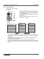
1.5.2
Introduction 1
Using the FX2N-1RM individually
FX2N-1RM
BANK
OUT
RUN
Extension block for FX2N-1RM
(FX2N-16EYT-ESS/UL)
OUT 0
1
2
3
4
5
6
7
OUT 0
1
2
3
4
5
6
7
OUT 0
1
2
3
4
5
6
7
POWER
POWER
POWER
OUT 0
1
2
3
4
5
6
7
OUT 0
1
2
3
4
5
6
7
OUT 0
1
2
3
4
5
6
7
Y20~Y37
Y40~Y57
ERR
STEP
DEG
ON
OFF
BANK
OUT
STEP
FNC
DEL
TEACH
RUN
COPY
7
4
1
STOP
0
8
5
2
9
ON
OFF
6
ADJ
3
CLR
GO
Y00~Y17
48 points maximum
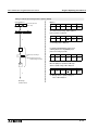
•
•
•
•
The FX2N-1RM-SET can connect the following extension block.
FX2N series extension block. (FX2N-16EYT-ESS/UL)
Up to 48 output points can be connected to the FX2N-1RM. Octal numbers are assigned as
output Nos. from the extension block nearest to the FX2N-1RM (Y00 to Y07, Y10 to Y17, . . .
Y50 to Y57).
Only extension blocks with dedicated output are allowed to be connected to the FX2N-1RM.
(If extension blocks with dedicated input are connected, no input can be received and input
Nos. are not assigned.)
Two or more FX2N-1RM cannot connected without connecting the PLC main unit.
1-7
FX2N-1RM-E-SET Programmable Cam Switch
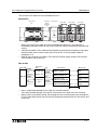
1.5.3
Introduction 1
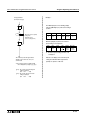
CC-Link connection
<Using the FX2N-1RM individually>
Composition
FX2N-1RM
BANK
FX2N-32CCL
• When one FX2N-1RM is used in CC-Link, FX2N-32CCL
interface block (here in after referred to as FX2N-32CCL)
is connected with the connector for the extension block
connection FX2N-1RM.
• FX2N-32CCL can not be used together with the output
extension blocks.
• Refer to user’s manual of this bale in FX2N-32CCL and
connection with master unit.
OUT
RUN
ERR
STEP
DEG
ON
FX2N-32CCL
OFF
BANK
OUT
STEP
FNC
DEL
TEACH
RUN
COPY
ADJ
7
4
1
STOP
0
8
5
2
9
ON
OFF
POWER
LRUNE LERRE RDE SD
6
3
CLR
GO
Flow data
FX2N-1RM
FX2N-32CCL
Master unit
BFM#2(Bank specification)
BFM#8(RWw0)
Remote register RWw
BFM#3(Command)
BFM#0(RY00~0F)
Remote output RY
BFM#8(Present angle)
BFM#11(RWr3)
Remote register RWr
BFM#9(Rotational speed)
BFM#12(RWr4)
Remote register RWr
BFM#10~#12(State of output)
BFM#8~#10(RWr0~2)
Remote register RWr
BFM#28(Status)
BFM#0(RX00~0F)
Remote input RX
Always
•
•
•
Link scanning
The communication between FX2N-1RM and FX2N-32CCL is always done while energizing
the power supply. The communication between FX2N-32CCL and master unit is done to the
link scanning.
When setting the number of occupied stations of FX2N-32CCL is 1, BFM#9 of FX2N-1RM
(rotational speed) is not transmitted.
Set the number of occupied stations in 2 when you transmit the rotational speed.
When cc-link is connected, setting and the program for the communication are unnecessary
in FX2N-1RM. Refer to each user’s manual for setting the communication in FX2N-32CCL and
master unit
1-8
FX2N-1RM-E-SET Programmable Cam Switch
Introduction 1
<Two or more FX2N-1RM units are connected with PLC>
Composition
F X
L
C O M
N
E x te
b lo
E x te
u n
s e r ie s
P L C
2 N
2 4 +
X 1
X 2
X 3
X 4
X 7
IN
X 1 0
0
X 1 4
X 1 3
1
2
3
4
5
X 1 5
6
n s io n
c k s
n s io n
its
F X
O U T 0
1
2
3
4
5
6
7
X 1 6
7
P O W E R
1 0 1 1 1 2 1 3 1 4 1 5 1 6 1 7
-3 2 C C L
2 N
B A N K
F X
2 N
O U T
•
•
•
Y 4
Y 5
Y 6
0
1
2
3
4
5
6
7
1 0 1 1 1 2 1 3 1 4 1 5 1 6 1 7
Y 1 0
Y 1 2
C O M 3 Y 1 1
Y 1 3
Y 1 4
R D E
-1 R M
F X
B A N K
O U T
R U N
R U N
E R R
E R R
D E G
S T E P
O U T
S T E P
F N C
D E L
T E A C H
R U N
C O P Y
A D J
7
4
O U T 0
1
2
3
4
5
6
7
2 N
D E G
2 N
O U T
R U N
E R R
S T E P
O N
O N
O F F
O F F
-1 R M
D E G
O N
O F F
S D
B A N K
C P U .E
Y 1 5
L E R R E
F X
B A N K
P O W E R
L R U N E
P R O G .E
Y 3
-1 R M
O U T
S T E P
-3 2 C C L
R U N
Y 2
2 N
P O W E R
B A T T .V
Y 1
F X
1
S T O P
0
8
5
2
9
O N
O F F
B A N K
S T E P
F N C
D E L
T E A C H
R U N
C O P Y
A D J
7
6
4
3
C L R
O U T
1
G O
S T O P
0
8
5
2
9
O N
O F F
6
O U T
S T E P
F N C
D E L
T E A C H
R U N
C O P Y
A D J
7
4
3
C L R
B A N K
1
G O
S T O P
0
8
5
2
9
O N
O F F
6
3
C L R
G O
When two or more FX2N-1RM units ate connected and used for PLC, FX2N-32CCL is
connected at the right of the main unit of PLC and FX2N-1RM is connected at the end of the
system.
Connected number of FX2N-1RM and the limitation concerning the connection of the output
extension block are the same as time when FX2N-32CCL is not connected. (Refer to
paragraph 1.5.1)
Refer to user’s manual of this bale in FX2N-32CCL for power supply wiring of FX2N-32CCL
and connection with master unit.
Flow of data
FX2N-1RM
FROM
instruction
TO
instruction
FX2N series
PLC
Internal relay
Output relay
FROM
instruction
TO
instruction
BFM data FROM
instruction
TO
instruction
TO
instruction
Data(word)
device
FROM
instruction
FX2N-32CCL
Master unit
Dedicated to write
BFM#0~#7(RX00~7F)
Remote input
(RX)
Dedicated to read
BFM#0~#7(RY00~7F)
Remote output
(RY)
Dedicated to write
BFM#8~#23(RWr00~0F)
Remote register
(RWr)
Dedicated to read
BFM#8~#23(RWw00~0F)
Remote register
(RWw)
Link scanning
•
•
Data is read/write by between FX2N-1RM, PLC and FX2N-32CCL.
The communication between FX2N-32CCL and master unit is done to the link scanning.
When cc-link is connected, setting and the program for the communication are unnecessary
in FX2N-1RM. Refer to each user’s manual for setting the communication in FX2N-32CCL and
master unit
1-9
FX2N-1RM-E-SET Programmable Cam Switch
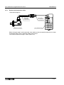
1.5.4
Introduction 1
Resolver and connection cable
<Connection diagram>
Relay cable
F2-RS-5CAB
5m(196.85 inch)
Resolver F2-720RSV
Signal cable
FX2N-RS-5CAB
5m(196.85 inch)
FX2N-1RM main body
When the signal cable is not long enough, relay cables can be connected for extension as shown
in the figure above. Two or more relay cables can be used.
The maximum extension length is 100 m (3937 inch).
1-10
FX2N-1RM-E-SET Programmable Cam Switch
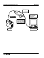
1.5.5
Introduction 1
Connecting the peripheral equipment
< Data setting panel >
This panel allows data setting, data read, monitoring, copy between banks, teaching and fine
adjustment in the RUN mode.
Data setting panel
When removing the data setting panel, press the
attachment buttons provided at the top and the
bottom of the data setting panel.
FX2N-1RM
1-11
FX2N-1RM-E-SET Programmable Cam Switch
Introduction 1
< Personal computer >
A personal computer allows save and transfer of programs.
FX-232AW
FX-232AWC
FX-232AWC-H
FX
Applicable software
FX-PCS/WIN-E
GX Developer
(compatible with FX2N)
FX-422CAB0
F2-232CAB-1
(Use the D-sub 9pin as
the RS-232C connector
on the computer side)
FX2N-1RM
Personal computer
1-12
FX2N-1RM-E-SET Programmable Cam Switch
Introduction 1
<FX-20P-E>
The FX-20P-E allows the save and transfer of programs.
Use the FX-20P-RWM and a memory cassette to save programs.
FX-EPROM-8
FX-EEPROM-8
FX-20P-E
(compatible with FX2N)
FX-20P-RWM
FX-20P-CAB0
FX2N-1RM
1-13
FX2N-1RM-E-SET Programmable Cam Switch
1.5.6
Introduction 1
Cautions on use of a personal computer and the FX-20P-E
•
Only the program transfer function is available from a personal computer or the FX-20P-E to
the FX2N-1RM. The monitor function, the test function, the current value change function,
etc. are not available. (If such a function is used, a communication error occurs.)
Set the parameter as shown in the table below when transferring programs.
PLC model
FX2N
Memory capacity
8K step
File register
14 blocks (7,000 points)
Comment
0 block
M500∼M1023
S500∼S999
Latch range
C100∼C199
C220∼C255
Equivalent to values at time
of shipment from plant
D200∼D511
Program
All NOP (unattended)
If a program is transferred while the parameters are not set as shown above, a parameter
mismatch error or program mismatch error occurs.
•
Use a personal computer or the FX-20P-E only when FX2N-1RM is in PRG mode (halt condition).
The following may occur if they are used in RUN mode:
- FX2N-1RM is overloaded because the power is also supplies the peripheral equipment
and the FX2N-1RM stops.
- Communication between the peripheral equipment and FX2N-1RM becomes very slow
and a communication error takes place.
• When a program is transferred from a personal computer or the FX-20P-E, D1000 to D7143
correspond to BFM #1000 to BFM #7143, D7144 to D7145 correspond to BFM #0 to BFM
#1, and D7146 to D7159 correspond to BFM #13 to BFM #26.
At this time, the angle data and FNC instructions (FNC70 to 75, 90) among D1000 to D7159
are fixed to a double value (720 degrees/rotation) without regard to the setting of the
resolution (selected by the data setting panel or BFM #0 b6).
D7144 (BFM #0), D7146 (BFM #13) and D7148 (BFM #15) are treated by one time value.
Example
ON/OFF angle
At BFM #1000=100°, D1000 becomes 200.
FNC
When FNC 70 (BCD output) is set, D1000 becomes 2140. Continuing D1001
reaches twice value at strobing ON time.
D1000 = ( 1000 + 70 ) × 2 = 2140
fixed FNC
value of
value number D1000
When strobing ON time is 50ms, D1001 becomes 100.
When individual automatic angle advance function is set, D6376 to D6393 reach
the value twice the number of rotations, the turning ON angles, and the turning
OFF angles of S0 to S6.
1-14
FX2N-1RM-E-SET Programmable Cam Switch
•
Introduction 1
The table below shows the applicable versions for personal computers and the FX-20P-E.
FX2N-1RM
Peripheral equipment
V. 2.20 or earlier
FX-PCS/WIN-E(V.1.00 to V.2.11)
V. 2.30 or later
applicable
FX-PCS/WIN-E(V.3.00 or later)
not applicable
applicable
GX Developer
not applicable
applicable from
SW2D5-GPPW-E
FX-20P-E
applicable from V. 3.00
1-15
FX2N-1RM-E-SET Programmable Cam Switch
Introduction 1
Memo
1-16
FX2N-1RM-E-SET Programmable Cam Switch
1
Introduction
2
Installation
3
Specifications
4
External Wiring
5
Extension Block Specifications and External Wiring
6
Basic Setting
7
BFM Assignment
8
Program Operating Procedures
9
Monitor
10
Test
11
Diagnostics
Appendix
FX2N-1RM-E-SET Programmable Cam Switch
FX2N-1RM-E-SET Programmable Cam Switch
2.
Installation 2
Installation
This section describes how to install the FX2N-1RM and the resolver.
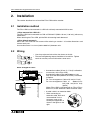
2.1
Installation method
The FX2N-1RM can be mounted via a DIN rail or directly mounted with M4 screws.
< When mounted via a DIN rail >
The FX2N-1RM can be mounted to a DIN rail DIN 46277 (Width: 35 mm (1.38 inch)) without any
modification.
When removing the FX2N-1RM, pull the DIN rail mounting hook downward.
< When directly mounted >
Mount the FX2N -1RM with M4 screws while referring to section 1.4 Outside dimensions and
name of each part.
Assure clearance of 1 to 2 mm (0.04 to 0.08 inch) between units.
Wiring
6.2mm
6.2mm
(0.24inch) (0.24inch)
or less
or less
• Use crimp-style terminals of the size shown on the left.
• The terminal tightening torque should be 0.5 to 0.8 N⋅m. Tighten
terminals securely so that malfunction cannot occur.
Use M3
When arranged in 2 rows
Main unit
Extension cable
FX2N-1RM
50 mm (1.97 inch) or more
2.2
• An extension cable of 55 mm (2.17 inch) is offered as
an accessory of the FX2N-1RM.
An extension cable of FX0N-30EC(300mm,11.81
inch) and FX0N-65EC(650mm,25.59 inch) are offered
as options.
For 1-row arrangement: Cable of 55 mm(2.17 inch)
For 2-row arrangement: Cable of
300mm(11.81
inch), 650 mm(25.59 inch)
(option)
(When FX2N-1RM is connected with an FX2NC/FX3UC
series PLC, these extension cables cannot be used.)
• A cable is built in an extension block.
•
When connecting an
extension cable, fold it and
accommodate it in the
connector cover of the
counterpart equipment as
shown in the figure on the
right.
2-1
FX2N-1RM-E-SET Programmable Cam Switch
Installing the resolver
When installing a resolver, pay rigid attention to eccentricity of the rotation shaft and tilt of the
shaft. Attach a resolver to a machine via an elastic coupling.
Example: NA-15 (φ10 (0.39 inch) × φ10 (0.39 inch)) manufactured by Nihon Miniature Coupling
Coupling
Resolver
Screw (M4)
10(0.39)
1°30'(1.3 degrees) or less
35(1.38)
φ10(0.39)
φ22(0.87)
φ10(0.39)
φ 50
0.1(0.004) or less
2.3
Installation 2
7
(1.9
)
Manufacturer name
Series name
Nihon Miniature Coupling
NA Series
Eagle Kogyo
Asa Denshi Kogyo
FCS Series
GJ Series
10(0.39)
Enlarged view of coupling [Unit: mm(inch)]
Relay cable
F2-RS-5CAB
5m(196.85 inch)
Resolver F2-720RSV
Signal cable
FX2N-RS-5CAB
5m(196.85 inch)
FX2N-1RM main body
When the signal cable is not long enough, relay cables can be connected for extension as
shown in the figure above.
2-2
FX2N-1RM-E-SET Programmable Cam Switch
Installation 2
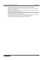
Cautions on installation
• Use the unit in the environment in accordance with the environmental specifications
described in Paragraph 3.1 in this manual.
Do not use the unit in a place with dust, soot, conductive dust, corrosive gases (Salt air,
Cl2, H2S, SO2, NO2, etc.) or flammable gases. Do not use in places exposed to high
temperature, condensation, wind and rain, vibrations or possible impacts.
If the unit is used in such a place, electrical shocks, fires, malfunction, damage to the
unit or deterioration in the performance of the unit may occur.
• Do not drop cutting chips and electric wire chips into the ventilation window of the PLC
while drilling screw holes or performing the wiring work.
If such chips are dropped, fires, failures or malfunction may occur.
• When the installation work is completed, remove the dust preventive sheet attached to
the ventilation window of the PLC.
If the sheet is not removed, fires, failures or malfunction may occur.
• Connect cables such as extension cables and memory cassettes securely to the
specified connectors respectively.
If such cables and cassettes are not connected correctly, malfunction may occur
caused by imperfect contact.
Note
• When a dust preventive sheet is provided on an extension block,
adhere it on the ventilation window during the installation/wiring
work.
• Never install the unit on the floor, on the ceiling or in the vertical
direction. If the unit is installed in such a way, the temperature
may become too high.
Make sure to install the unit in the horizontal direction as shown
in the figure on the right.
• Arrange extension cables so that connectors on the left side of
extension units, extension blocks, and special units are
connected on the side near the main unit.
• Assure clearance of 50 mm (1.97 inch) or more between the unit
main unit and other equipment or structure. Keep a high voltage
cable, high voltage equipment, and power equipment from the
unit as much as possible.
Cautions on wiring
• Make sure to shut down all the phases of the power supply outside the PLC before
starting the installation/wiring work.
If all the phases are not shut down, electrical shocks or damage to the product may
occur.
• Make sure to attach the terminal covers offered as accessories before supplying the
power and operating the product after the installation/wiring work has been finished.
If the covers are not attached, electrical shocks may occur.
2-3
FX2N-1RM-E-SET Programmable Cam Switch
Installation 2
Note
•
•
•
•
Never let the signal input line and the signal output line of the PLC go through the same
cable.
Never let the signal input line and the signal output line of the PLC go through the duct
together with other power lines and output lines.
Never bind the signal input line and the signal output line of the PLC together with other
power lines and output lines.
When the cautions above are observed, no problem should be expected with regard to noise
even if the input/output wiring is extended to 50 to 100 m (1968.5 to 3937.0 inch). It is
recommended, however, to set the wiring length to 20 m (787.4 inch) or less to assure safety.
Extension cables are most susceptible to noise. When wiring them, keep them away from the
output of the PLC and other power lines by at least 30 to 50 mm (1.18 to 1.97 inch).
2-4
FX2N-1RM-E-SET Programmable Cam Switch
1
Introduction
2
Installation
3
Specifications
4
External Wiring
5
Extension Block Specifications and External Wiring
6
Basic Setting
7
BFM Assignment
8
Program Operating Procedures
9
Monitor
10
Test
11
Diagnostics
Appendix
FX2N-1RM-E-SET Programmable Cam Switch
FX2N-1RM-E-SET Programmable Cam Switch
3.
Specifications 3
Specifications
This section describes the specifications of the FX2N-1RM and the resolver.
Cautions on design
• Provide a safety circuit outside the PLC so that the entire system can operate
conservatively in any case even if an error has occurred in the external power supply or
a failure has occurred in the PLC.
If a safety circuit is not provided, an accident may occur caused by malfunction or
erroneous output.
1 ) Make sure to construct a circuit outside the PLC as to an emergency stop circuit, a
protection circuit, an interlock circuit for reverse operations such as normal rotation
and reverse rotation and an interlock circuit to prevent mechanical damages such as
for upper and lower limits for positioning.
2 ) When the PLC CPU has detected an abnormality by the self-diagnosis function such
as a watchdog timer error, all the outputs are turned off. When an abnormality has
occurred in the I/O control area, etc. which cannot be detected by the PLC CPU, the
output control may be disabled.
Design the external circuit and the mechanism so that the machine can operate
conservatively in such cases.
3 ) The output current of the service power supply for the sensor varies depending on the
model and existence of extension blocks. If overload has occurred, the voltage is
automatically dropped, the input to the PLC is disabled, and all the outputs are turned
off.
Design the external circuit and the mechanism so that the machine can operate
conservatively in such a case.
4 ) When a failure has occurred in a relay, transistor, TRIAC, etc. in the output unit, the
output may be kept turned ON or OFF.
Design the external circuit and the mechanism so that the machine can operate
conservatively with regard to an output signal which may lead to a serious accident.
3-1
FX2N-1RM-E-SET Programmable Cam Switch
3.1
Specifications 3
General specifications
Ambient
0 to 55°C when operating and -20 to 70°C when stored
temperature
Ambient
humidity
Vibration
resistance
35 to 85% RH (no condensation) when operating
When installed on
DIN rail
When installed
directly
Frequency
(Hz)
Acceleration
(m/s2)
Half amplitude
(m/m)
10 to 57
–
0.035
57 to 150
4.9
–
10 to 57
–
0.5
(2G maximum)
Sweep Count for X,
Y, Z: 10 times
(80 min in each
direction)
Impact
resistance
98 m/s2 Acceleration, Action time: 11ms, 3 times by half-sine pulse in each direction X, Y,
and Z
Noise
resistance
By noise simulator at noise voltage of 1,000 Vp-p, noise width of 1 µs rise time of 1 ns and
period of 30 to 100 Hz
Dielectric
withstand
voltage
500 V AC for one minute
Insulation
resistance
5 MΩ or more by 500 VDC megger Between all terminals as a whole and ground terminal
Grounding
Class D grounding (grounding resistance: 100 Ω or less)
<Common grounding with a heavy electrical system is not allowed>*1
Ground the PLC independently or jointly.
Between all terminals as a whole and ground terminal
Working
Free from corrosive or flammable gas and excessive conductive dust
atmosphere
Working
altitude
*1:
FX 2N -1RM
<2000m*2
Other
equipment
Dedicated grounding (best)
FX 2N -1RM
Other
equipment
Common grounding (good)
FX 2N -1RM
Other
equipment
Common grounding (not allowed)
*2: Do not use the PLC under pressure higher than the atmospheric pressure. Doing so may
damage the PLC.
3-2
FX2N-1RM-E-SET Programmable Cam Switch
3.2
3.3
Specifications 3
Performance specifications
Applicable PLC
The bus of an FX2N, FX3U, FX2NC and FX3UC series PLC can be connected.
A single drive is also possible. (Refer to subsection 1.5.1.)
Program memory
Built-in EEPROM memory (no battery)
Number of cam
output points
48 internal output points. Data is read by PLC. In addition, 48 points can be connected when transistor output extension blocks or triac output extension blocks
are connected. (When extension blocks are connected, up to 32 points can be
turned on at a time.)
Detector
Brushless resolver (F2-720RSV for F2-32RM)
Control resolution
720 divisions/rotation (0.5 degree) or 360 divisions/rotation (1 degree)
Response speed
415 r/min/0.5 degree or 830 r/min/degree
When the current angle transfer function is used, response speed becomes
207r/min/0.5degree or 415r/min/degree.
Number of program
banks
8 banks (specified by PLC) or 4 banks (specified by external input)
Setting unit
Dedicated data setting unit (integrated add-on type)
Peripheral equipment for PLC via PLC (Sequence program is required.)
Number of times of
ON/OFF
8 times/cam output
Input
2 bank input points (code input of 0 to 3), 24 VDC, 7 mA, response time 3 ms,
photocoupler isolation
Setting switch
RUN/PRG selector switch and 16 keys (input from data setting panel)
LED indication
POWER, RUN, ERROR, 7-segment × 7 digits, LED × 4
Resolver specifications
Excitation method
Two-phase excitation, 1-phase output (5 kHz)
Mechanical allowable 3000r/min
rotation speed
Cable distance
100 m (3937 inch) maximum
Vibration resistance
10 to 2000 kHz (15 G maximum), 2 hours in each of 3 directions
Impact resistance
50 G, 11 ms, 3 times in each of 6 directions
Abrasion torque
0.0118N⋅m or less
Protection structure
IP52
Ambient temperature -10 to +85°C
3-3
FX2N-1RM-E-SET Programmable Cam Switch
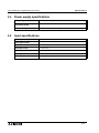
3.4
Specifications 3
Power supply specifications
Rated voltage
24 VDC+10%, -15%
Allowable instantaneous power 5ms
interruption period
Power consumption
3.5
3 W (when operating individually), 5 W (at 32 points output ON)
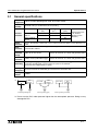
Input specifications
Input signal voltage
24 VDC ±10%
Input signal current
7 mA/24 VDC
Input ON current
4.5 mA or more
Input OFF current
1.5 mA or less
Input response time
Approximately 3 ms
Input signal format
Contact input or NPN/PNP open collector
Circuit isolation
Photocoupler isolation
3-4
FX2N-1RM-E-SET Programmable Cam Switch
1
Introduction
2
Installation
3
Specifications
4
External Wiring
5
Extension Block Specifications and External Wiring
6
Basic Setting
7
BFM Assignment
8
Program Operating Procedures
9
Monitor
10
Test
11
Diagnostics
Appendix
FX2N-1RM-E-SET Programmable Cam Switch
FX2N-1RM-E-SET Programmable Cam Switch
4.
External Wiring 4
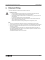
External Wiring
This section describes wiring of the power supply and the input.
Cautions on wiring
• Do not connect the AC power supply to DC I/O terminals or DC power terminals.
If such connection is performed, the FX2N-1RM may burned out.
• Do not perform wiring from the outside to an unused terminal [ ⋅ ] of the main unit or an
extension block.
If such wiring is performed, the unit may be damaged.
• Perform Class D grounding to the ground terminal in the FX2N-1RM or the main unit
using an electric wire of 2 mm2 or more.
However, do not perform common grounding with a strong electric system.
Note
•
Turn on or off simultaneously the power of the PLC and the power of the FX2N-1RM.
•
•
Use an electric wire of 2 mm2 or more as a power line so that voltage drop can be prevented.
Even if an instantaneous power interruption of 5 ms or less has occurred, the FX2N-1RM
continues its operation.
If a considerably long power interruption or an abnormal voltage drop has occurred, the
FX2N-1RM is stopped and the output is turned off. When the power is recovered, the FX2N1RM automatically restarts operation
(if the RUN/PRG selector switch is set to "RUN").
4-1
FX2N-1RM-E-SET Programmable Cam Switch
4.1
External Wiring 4
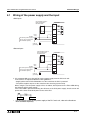
Wiring of the power supply and the input
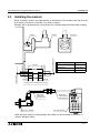
<Sink input>
Use transistors when a
bank is switched in
the RUN mode.
FX2N-1RM
B0
B1
3.3kΩ
3.3kΩ
S/S
+10%
DC24V -15%
*1
The service power supply of
the PC can be used within
the allowable capacity.
24+
24-
Class D
grounding
<Source input>
Use transistors when a
bank is switched in
the RUN mode.
FX2N-1RM
B0
B1
DC24V
+10%
-15%
The service power supply of
the PC can be used within
the allowable capacity.
3.3kΩ
3.3kΩ
S/S
*1
24+
24-
Class D
grounding
*1 It is recommended to use the 24V DC service power supply from the PLC main unit.
If two sources are required, follow the below guidelines:
- Supply power to the FX2N-1RM before or at the same time the PLC is powered.
- The power supplies may be cut the same time after ensuring system safety.
When using the service power supply of PLC as follows, do not power on the FX2N-1RM during
the ON state of PLC power supply.
If the FX2N-1RM is powered on during the ON state of the PLC power supply, inrush current will
power off the internal electrical power source of the PLC.
PLC
•
FX2N-1RM
For the capacity of the service power supply of the PLC main unit, refer to the Hardware
Manual offered separately.
4-2
FX2N-1RM-E-SET Programmable Cam Switch
1
Introduction
2
Installation
3
Specifications
4
External Wiring
5
Extension Block Specifications and External Wiring
6
Basic Setting
7
BFM Assignment
8
Program Operating Procedures
9
Monitor
10
Test
11
Diagnostics
Appendix
FX2N-1RM-E-SET Programmable Cam Switch
FX2N-1RM-E-SET Programmable Cam Switch
5.
Extension Block Specifications and External Wiring 5
Extension Block Specifications and
External Wiring
This section describes the specifications and the wiring of the FX2N-16EYT.
When other extension blocks dedicated to output are used, refer to the Hardware Manual of the
FX2N Series PLC in accordance with the model used.
5.1
Extension block specifications (transistor output type)
External power supply
5 to 30 VDC
Circuit isolation
Photocoupler isolation
Resistance load 0.5 A/point, 0.8 A/4 points common, 1.6 A/8 points common
Maximum load
Inductive load
12 W/24 VDC
Ramp load
1.5 W/24 VDC
0.1 mA/30 VDC
Open circuit leak current
Response time
•
5.2
OFF → ON
0.2 ms or less (0.2 A or more)
ON → OFF
0.2 ms or less (0.2 A or more)
The general specifications are equivalent to those of the FX2N-1RM. (Refer to Paragraph
3.1.)
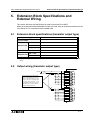
Output wiring (transistor output type)
FX 2N -16EYT
DC24V
MC
2A
COM1
Y0
Y1
Y2
Y3
Y4
Y5
Y6
Y7
2A
COM2
Y0
Y1
Y2
Y3
Y4
Y5
Y6
Y7
No fuse is built in these output circuits
of the programmable controller.
Provide a fuse appropriate to each
load so that the programmable
controller Board wiring of the
programmable controller is not melt
down by break of output elements
caused by load short-circuit, etc.
5-1
FX2N-1RM-E-SET Programmable Cam Switch
Extension Block Specifications and External Wiring 5
Cautions on wiring
• Do not connect the AC power supply to DC I/O terminals or DC power terminals.
If such connection is performed, the FX2N-1RM may burned out.
• Do not perform wiring from the outside to an unused terminal [ ⋅ ] of the main unit or an
extension block.
If such wiring is performed, the unit may be damaged.
5-2
FX2N-1RM-E-SET Programmable Cam Switch
1
Introduction
2
Installation
3
Specifications
4
External Wiring
5
Extension Block Specifications and External Wiring
6
Basic Setting
7
BFM Assignment
8
Program Operating Procedures
9
Monitor
10
Test
11
Diagnostics
Appendix
FX2N-1RM-E-SET Programmable Cam Switch
FX2N-1RM-E-SET Programmable Cam Switch
6.
Basic Setting 6
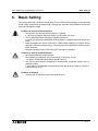
Basic Setting
This section describes the basic setting of the FX2N-1RM including handling of the RUN and
STOP modes, specification of the bank No., setting of the automatic angle advance function and
setting of the reference angle.
Cautions on start-up and maintenance
• Do not touch any terminal while the power is supplied.
If a terminal is touched, electrical shocks or malfunction may occur.
• Turn off the power before cleaning or tightening terminals.
If cleaning or tightening is performed while the power is supplied, electrical shocks may
occur.
• Read thoroughly the manual and confirm safety before modifying a program during
operation, performing forced output, performing the RUN operation or performing the
STOP operation.
Erroneous operation may cause mechanical damages or accidents.
Cautions on start-up and maintenance
• Do not disassemble or modify the unit.
Disassembly or modification may cause failures, malfunction or fires.
* For repair, contact Mitsubishi Electric System Service
• Turn off the power before connecting or disconnecting connection cables such as
extension cables.
If such cables are connected or disconnected while the power is turned on, failures or
malfunction may occur.
Cautions on Disposal
• Treat the unit as industrial waste when disposing of it.
6-1
FX2N-1RM-E-SET Programmable Cam Switch
6.1
Basic Setting 6
Handling of the RUN and PRG modes
The FX2N-1RM offers two modes, RUN (operation) and PRG (program). These modes can be
switched using the following procedure.
(In the PRG mode, the FX2N-1RM stops operation.)
< Built-in RUN/PRG selector switch >
T h e RU N m o d e a n d t h e P R G m o d e c a n b e sw i t c h e d by
manipulating the RUN/PRG selector switch built in the main unit.
When the switch is set to the RUN side, operation is performed.
When the switch is set to the PRG mode, operation is stopped and
the download of programs is enabled.
RUN
PRG
< Changing over the RUN and PRG modes from the data setting panel >
The RUN mode and PRG mode can be switched by manipulating the keys provided on the data
setting panel.
To select the RUN mode: [RUN] → [GO]
To select the PRG mode: [STOP] → [GO]
The RUN to PRG operation with data setting panel can be prohibited with BFM#0 b6 or the data
setting panel.
This function is added from the product since V2.20.
< Changing over the RUN and PRG modes from the PLC >
The RUN mode and PRG mode can be switched by giving a TO instruction from the PLC.
The RUN/PRG command write destination is provided in b0 and b1 of BFM #3.
BFM #3
b0: Selects the RUN mode when set to ON from OFF (when the rising edge is detected).
b1: Selects the PRG mode when set to ON from OFF (when the rising edge is detected).
* b0 and b1 should not be set to ON from OFF at the same time.
•
•
•
•
Change in the status is detected in any procedure to change-over the RUN mode and the
PRG mode.
When the power is turned on, the mode is set in accordance with the setting of the RUN/PRG
selector switch built in the FX2N-1RM.
The RUN LEDs on the FX2N-1RM and the data setting panel are lit while the RUN mode is
selected.
The RUN LEDs on the FX2N-1RM and the data setting panel are extinguished while the PRG
mode is selected.
When switching from PRG to RUN, FX2N-1RM does not output by the position where the
resolver is stopped occasionally. (Dead zone)
When the resolver starts rotating, FX2N-1RM is normally output.
When switching from PRG to RUN, the product since V2.20 is normally output wherever the
resolver has stopped.
6-2
FX2N-1RM-E-SET Programmable Cam Switch
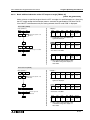
6.2
Basic Setting 6
Specifying the bank
The FX2N-1RM can store two or more programs, and execute an arbitrary program in accordance
with an external input to the FX2N-1RM or an instruction given by the PLC main unit.
Up to 4 banks are available for an external input. Up to 8 banks are available for an instruction by
the PLC.
•
Setting the bank specification method
Set which one between the external input and the PLC is used to specify a bank.
To select either one, give a TO instruction from the data setting panel or the PLC main unit.
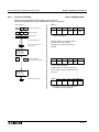
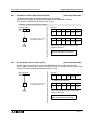
< Setting by the data setting panel >
FNC
3
GO
Select the bank
specification method.
ON/OFF
Every time this key is
pressed, the PLC (The
OFF LED flashes.) or the
external input (The ON
LED flashes.) is selected
alternately.
GO
Select the
specification method
based on flashing of
the LED, and
confirm it by
pressing the [GO]
key.
< Setting by the PLC >
The bank specification method write destination is provided in b3 of BFM #0.
BFM #0
b3: OFF → A bank is specified by an external input.
ON → A bank is specified by the PLC.
Set to specify the Bank from the PLC without fail when you use the current angle transfer
function.
•
Bank specification method
Specify the program No. to be executed using the method selected by the procedure
described in "Setting the bank specification method" above (bank specification).
< Bank specification by the external input >
Specify an arbitrary program No. from the B0 and B1 terminals. (For the wiring, refer to "4.1
Power supply and input wiring".)
To change-over the program No. to be executed while a program is running (RUN mode), use
transistors.
The input response time of the FX2N-1RM is approximately 3 ms. If relays or with-contact
switches are used, a program other than the specified one may be executed while the bank
change-over operation is being performed.
Specified program No.
B1
B0
0
OFF
OFF
1
OFF
ON
2
ON
OFF
3
ON
ON
< Bank specification by the PLC >
The bank specification write destination is provided in BFM #2. Write the program No. to be
executed using a TO instruction.
The effective values are 0 to 7.
6-3
FX2N-1RM-E-SET Programmable Cam Switch
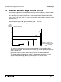
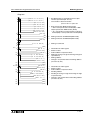
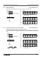
6.3
Basic Setting 6
Automatic angle advance function
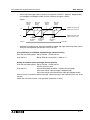
The automatic angle advance function performs the output ON/OFF operation in advance by an
arbitrary angle (angle advance quantity) in accordance with the rotation speed of the resolver.
By using this function, delay in the mechanical operation generated during rotation at high speed
can be compensated.
The setting of this function becomes the common set point for the on angle and the off angle
outputs Y00 to Y07 and Y10 to Y17.
The response speed can be used by 830 r/min (1 degree mode), 415 r/min (0.5 degrees mode).
Angle
advance
quantity
(degrees) G
180 degrees maximum
S6
S5
F
S4
E
S3
D
S2
C
B
A
S1
S0
a
400 r/min maximum
b
c
d
e
f
g Rotation speed (r/min)
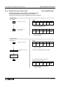
The automatic angle advance function can be set in 7 steps from S0 to S6 as shown in the figure
above. Enter the rotation speed (a to g) and the angle advance quantity (A to G) for each step
from the data setting panel or the PLC main unit.
The smallest rotation speed should be set in S0 with the settings increasing in sequential order of
speed. (S0<S1<S2< . . . <S6)
When the automatic angle advance function is used, the rotation speed should be 400 r/min or
less and the angle advance quantity should be 180 degrees or less.
When the rotation speed is 0 (initial value), the angle advance quantity is treated as 0.
Whether or not the automatic angle advance function is used can be set from the data operation
panel and the PLC main unit.
For the input procedure from the data setting panel, refer to Paragraph 8.3.5.
For the input destination from the main unit, refer to Paragraphs 7.1 and 7.2.
(Data is written to BFM #0 and BFM #13 to BFM #26 by a TO instruction.)
6-4
FX2N-1RM-E-SET Programmable Cam Switch
Basic Setting 6
< Assignment of FNC Nos. and BFM Nos. >
S0
S1
S2
S3
S4
S5
S6
Input from data setting panel
(FNC No.)
Input from main unit
(BFM No.)
Rotation angle a
FNC 13
BFM #13
Angle advance quantity A
FNC 14
BFM #14
Rotation angle b
FNC 15
BFM #15
Angle advance quantity B
FNC 16
BFM #16
Rotation angle c
FNC 17
BFM #17
Angle advance quantity C
FNC 18
BFM #18
Rotation angle d
FNC 19
BFM #19
Angle advance quantity D
FNC 20
BFM #20
Rotation angle e
FNC 21
BFM #21
Angle advance quantity E
FNC 22
BFM #22
Rotation angle f
FNC 23
BFM #23
Angle advance quantity F
FNC 24
BFM #24
Rotation angle g
FNC 25
BFM #25
Angle advance quantity G
FNC 26
BFM #26
6-5
FX2N-1RM-E-SET Programmable Cam Switch
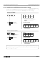
6.4
Basic Setting 6
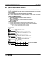
Individual automatic angle advance function
The automatic angle advance function performs the output ON/OFF operation in advance with an
arbitrary angle (angle advance quantity) in accordance with the rotation speed of the resolver.
This setting does an individual setting to the on angle and the off angle of output Y00 to Y03.
The executed program number can be used from bank 0 to bank 6.
Bank 7 must not be used. (Bank 7 is used to store the data of the individual automatic angle
advance function.)
The rotational speed response is as follows.
Response speed:1degree (360 degrees/revolution) mode . . . 415 r/min
0.5 degrees (720 degrees/revolution) mode . . . 207 r/min
Angle
advance
quantity
(degrees)
180 degrees maximum
S6
G
S5
F
S4
E
S3
D
S2
C
B
A
S0
a
•
•
•
•
400r/min (1 degree mode)
207r/min (0.5degrees mode)
maximum
S1
b
c
d
e
f
g
Rotation speed (r/min)
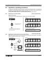
The individual automatic angle advance function can be set in 7steps from S0 to S6 as
shown in the figure above. Setting the rotation speed (a to g) and the angle advance quantity
(A to G) for each step.
Please set the smallest rotation speed to S0 and increase the settings sequentially.
(S0<S1< . . . <S6)
The rotation speed should be 400 r/min or less (1 degree mode), 207 r/min or less (0.5
degrees mode) and the angle advance quantity should be 180 degrees or less.
When the rotation speed is 0 (initial value), the angle advance quantity is treated as 0.
6-6
FX2N-1RM-E-SET Programmable Cam Switch
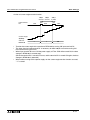
•
Basic Setting 6
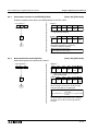
Please separate angle advance quantity from previous ON/OFF 1 degree (1 degree mode)
or 0.5 degrees (0.5 degrees mode) or more. (Refer to the figure 1 below)
Figure 1
ON angle
advance
quantity
OFF angle
advance
quantity
ON angle
advance
quantity
OFF angle
advance
quantity
Y0
Individual automatic angle
advance function unused.
Y0
Individual automatic angle
advance function used.
1 degree or
0.5 degrees
or more
1 degree or
0.5 degrees
or more
1 degree or
0.5 degrees
or more
0 degree
•
359 degrees
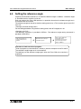
Selection of use/do not use, input of the rotational speed, and angle advance quantity can be
set by the data operation panel and the PLC main unit.
Use specification of individual automatic angle advance function
From the data setting panel : Set by FNC 05 → Refer to 8.3.6
From the PLC
: Bit5 of BFM #0 is turned ON → Refer to 7.2
Setting of rotational speed and angle advance quantity
From the data setting panel : Set by FNC 90 → Refer to 8.3.6
Input by one time value
From the PLC
: Input to BFM #6376 to #6459 → Refer to the next page
Input value equals advance angle (1 degree mode)
Input value equals twice the advance angle (0.5 degrees mode)
Please input the rotational speed and angle advance quantity after specifying the use of the
function.
(When the use of the function is not specified, it becomes an error.)
6-7
FX2N-1RM-E-SET Programmable Cam Switch
Basic Setting 6
When individual automatic angle advance function is used, addition of the crack of rotation speed
and angle advance quantity to buffer memory (BFM) is as follows.
• When the mode is selected 1
degree (360 degrees/
ON angle
OFF angle
revolution), input equals
advance quantity advance quantity
advance angle value.
6378
6377
When the mode is selected
6381
6380
0.5 degrees (720 degrees/
6384
6383
revolution), inputs equals
6387
6386
twice the advance angle
6390
6389
value. (input 10, advance
6393
6392
6396
6395
angle=5)
6399
6398
• The executed program
6402
6401
number can be used from
BFM No.
Rotation speed
Y0 S0
S1
S2
S3
S4
S5
S6
6376
6379
6382
6385
6388
6391
6394
Y1 S0
S1
S2
S3
S4
S5
S6
6397
6400
6403
6406
6409
6412
6415
Y2 S0
S1
S2
S3
S4
S5
S6
Y3 S0
S1
S2
S3
S4
S5
S6
6404
6407
6410
6413
6416
6405
6408
6411
6414
6417
6418
6421
6424
6427
6430
6433
6436
6419
6422
6425
6428
6431
6434
6437
6420
6423
6426
6429
6432
6435
6438
6439
6442
6445
6448
6451
6454
6457
6440
6443
6446
6449
6452
6455
6458
6441
6444
6447
6450
6453
6456
6459
Caution on batch transfer of programs
When the batch transfer of the program is done with the personal computer and FX20P-E when the Individual automatic angle advance function is used, all the data of
the rotational speed, the turning ON angle, and the turning OFF angle is treated by
the twice value.
6-8
FX2N-1RM-E-SET Programmable Cam Switch
6.5
Basic Setting 6
Setting the reference angle
Originally, the brushless resolver has an absolute reference angle. In addition, a reference angle
in accordance with a machine can be set.
Each set angle of the FX2N -1RM performs its operation based on the reference angle set in
accordance with the machine.
The reference angle can be set by the data setting panel or by a TO instruction given by the PLC
main unit.
< Setting by the data setting panel >
For the setting procedure using the data setting panel, refer to Paragraph 8.2.10.
< Setting by the PLC >
The reference angle data is provided in BFM #1. The reference angle setting command is
provided in BFM #3 b2.
Write the angle data to be
treated as the reference to
BFM #1.
Rotate the resolver, and stop it
in an arbitrary position.
Write "1 (ON)" to BFM #3 b2
(rising edge). By this
operation, the current position
of the resolver becomes the
angle set to BFM #1.
Caution on batch transfer of programs
Even if programs are transferred at a time by a personal computer or the FX-20P-E,
the reference angle image set is not transferred.
Accordingly, set the reference angle again after the FX2N-1RM or the resolver is
replaced.
6-9
FX2N-1RM-E-SET Programmable Cam Switch
6.6
Basic Setting 6
Handling the keyword
< Limitation of the function by the keyword >
When a keyword is registered, writing to the EEPROM is prohibited in the same way as the
EEPROM protect function. When programs are read by a personal computer or the FX-20P-E,
the registered keyword must be entered.
(Preventing theft of a program)
A keyword can be registered/deleted using the data setting panel, the personal computer
software and the FX-20P-E.
At this time, a keyword in a personal computer or the FX-20P-E is treated as "BBBBB{{{"
({{{ indicates a numeric from 1 to 999.).
The writing of any data from the buffer memory to the EEPROM is prohibited. Only the operations
shown in the table below are allowed to be set on the data setting panel.
< Operations enabled while a keyword is registered >
Operation by data setting panel
Read
Forced RUN/STOP
Read of reference angle
Write-protect of EEPROM
Deletion of keyword
Operation by buffer memory
(BFM)
Writing from BFM to EEPROM
is prohibited.
Any modification of BFM is
valid, and operation of FX 2N 1RM can be modified.
When the registered keyword is deleted, all the functions become available again.
An unknown keyword can be deleted by the entire program deletion procedure (Refer to
Paragraph 9.2.5.). Keep in mind that all other registered data is also deleted.
6-10
FX2N-1RM-E-SET Programmable Cam Switch
6.7
Basic Setting 6
Current angle transfer function
The current angle transfer function to transfers the current angle of the resolver to BFM#106 via
turning ON input terminal B1.
(This function has been included since V2.40)
The PLC is used together, and a highly accurate sampling by which an external input is made a
trigger can be done.
The response speed becomes 207r/min/0.5degree or 415r/min/degree.
Set to specify the bank from the PLC without fail when you use the current angle transfer
function.
< Setting by the data setting panel >
•
Set the method of specifying the bank by operating FNC3, "PLC".
Refer to Paragraph 8.3.4
• Set the current angle transfer function by operating FNC7, "Effective".
Refer to Paragraph 8.3.8
< Setting by the PLC >
•
•
BFM#0 b3 is turned ON, and the method of specifying the bank selects "PLC".
BFM#0 b7 is turned ON, and the Current Angle Transfer function is made effective.
b7: OFF → Current angle transfer function is Invalidity.
ON → Current angle transfer function is effective.
Program example
M8000
M0
Resolution: 1 degree
M1
Rotation derection of resolver: Clockwise
M2
Write protect of EEPROM: Write is enabled
M3
Bank specification method: PLC
M4
Automatic angle advance function: Un used
M5
Individual automatic angle advance function:
Un used
Prohibition of RUN to PRG operation:
Permission
Current angle transfer function: Used
M8000
M8000
M8000
M8000
M8000
M8000
M6
M8000
M7
M8002
BFM#106
Reading instruction
TO
K0
K0
K2M0
K1
Parameter setting (BFM#0)
FROM
K0
K106
D0
K1
BFM#106 → D0.
6-11
FX2N-1RM-E-SET Programmable Cam Switch
Basic Setting 6
< Action of current angle transfer function>
200µs
200µs
or more or more
ON
Input terminal
B1
ON
OFF
OFF
OFF
98
Current angle
(BFM#8)
Value of
BFM#106
•
•
•
•
1
2
-1
3
200µs
or more
4
5
99
100
101
102
103
104
6
5
100
Transfer the current angle of the resolver to BFM#106 by turning ON input terminal B1.
The input signal to input terminal B1 is necessary for both 200µS or more the turning ON
time and the turning OFF time.
When input terminal B1 turns ON the power supply of FX2N-1RM while turned ON, the data
storage in BFM#106 is not executed.
(When the terminal B1 is turned OFF once, and the terminal B1 is turned ON again, the data
storage in BFM#106 is executed.)
When neither turning ON the power supply nor the current angle transfer function are used,
”-1” is stored.
6-12
FX2N-1RM-E-SET Programmable Cam Switch
1
Introduction
2
Installation
3
Specifications
4
External Wiring
5
Extension Block Specifications and External Wiring
6
Basic Setting
7
BFM Assignment
8
Program Operating Procedures
9
Monitor
10
Test
11
Diagnostics
Appendix
FX2N-1RM-E-SET Programmable Cam Switch
FX2N-1RM-E-SET Programmable Cam Switch
7.
BFM Assignment 7
BFM Assignment
This section describes the buffer memory (BFM) of the FX2N-1RM.
When the FX2N Series PLC is connected to the FX2N-1RM, data can be read/written from/to the
BFM by FROM/TO instructions. (Refer to Paragraph 7.3.)
When two or three FX2N-1RM units are connected, FROM/TO instructions are available in only
the unit nearest to the PLC main unit.
The second and third FX2N-1RM units can write and read data from the PLC main unit via the
first FX2N-1RM unit.
7.1
BFM list
BFM No.
Name
Initial Remarks R: For read W: For write
value
K: Keep
⎯
#0
Initial setting
0
#1
Reference angle (ADJ)
0
×1 value (1 degree),
×2 value (0.5 degree)
Refer to Paragraph 6.5.
#2
#8002
Bank No. specification (00 to 07)
#9002 *1
0
#3
#8003
Command
#9003 *1
File register
assignment No.
W, K
D7144
W, K
D7145
Valid when bank specification
is set to PLC.
W
⎯
0
⎯
W
⎯
#4
Output prohibition (Y00 to Y17)
0
Prohibits output when each bit
is set to ON.
W
⎯
#5
Output prohibition (Y20 to Y37)
0
Prohibits output when each bit
is set to ON.
W
⎯
#6
Output prohibition (Y40 to Y57)
0
Prohibits output when each bit
is set to ON.
W
⎯
#7
Executed bank No.
⎯
⎯
W
⎯
R
⎯
#8
#8008
Current angle (degrees)
#9008 *1
⎯
#9
#8009
Rotation angle (r/min)
#9009 *1
⎯
⎯
R
⎯
#10
#8010
Output status (Y00 to Y17)
#9010 *1
⎯
Monitors output status when
each bit is set to ON/OFF.
R
⎯
#11
#8011
Output status (Y20 to Y37)
#9011 *1
⎯
Monitors output status when
each bit is set to ON/OFF.
R
⎯
#12
#8012
Output status (Y40 to Y57)
#9012 *1
⎯
Monitors output status when
each bit is set to ON/OFF.
R
⎯
⎯
W, K
D7146
W, K
D7147
W, K
D7148
W, K
D7149
#13
Speed of automatic angle advance
S0 (r/min)
0
#14
A n g l e a d va n c e q u a n t i t y o f
a u t o m a t i c a n g le a d va nc e S 0
(degrees)
0
#15
Speed of automatic angle advance
S1 (r/min)
0
#16
A n g l e a d va n c e q u a n t i t y o f
a u t o m a t i c a n g le a d va nc e S 1
(degrees)
0
×1 value (1 degree),
×2 value (0.5 degree)
×1 value (1 degree),
×2 value (0.5 degree)
⎯
×1 value (1 degree),
×2 value (0.5 degree)
7-1
FX2N-1RM-E-SET Programmable Cam Switch
BFM No.
Name
BFM Assignment 7
Initial Remarks R: For read W: For write
value
K: Keep
#26
Angle advance quantity of
a u t o m a t i c a ng l e a d va n c e S 6
(degrees)
0
#27
Undefined
⎯
Status
0
#28
#8028
#9028 *1
...
...
0
...
...
Speed of automatic angle advance
S6 (r/min)
...
...
#25
File register
assignment No.
⎯
W, K
D7158
W, K
D7159
⎯
⎯
⎯
⎯
R
⎯
×1 value (1 degree),
×2 value (0.5 degree)
#29
Error code
0
⎯
R
⎯
#30
Model code
K5410
⎯
R
⎯
#31
Unusable
⎯
⎯
⎯
⎯
#100 *2
Written ON angle
⎯
×1 value (1 degree),
×2 value (0.5 degree)
W
⎯
#101 *2
Written OFF angle
⎯
×1 value (1 degree),
×2 value (0.5 degree)
W
⎯
#102 *2
Written BFM No.
⎯
Range of setting 1000 to 7142
(BFM number of output ON
angle setting)
W
⎯
#103 *2
Reading BFM No.
⎯
Range of setting 1000 to 7142
(BFM number of output ON
angle setting)
W
⎯
#104 *2
Reading ON angle
⎯
×1 value (1 degree),
×2 value (0.5 degree)
R
⎯
#105 *2
Reading OFF angle
⎯
×1 value (1 degree),
×2 value (0.5 degree)
R
⎯
#106 *3
Data transfer destination of current
angle transfer function. Refer to
paragraph 6.7
-1
×1 value (1 degree),
×2 value (0.5 degree)
R
⎯
#1000
ON angle of bank No. 0, Y00, step
No. 0
FFFF
×1 value (1 degree),
×2 value (0.5 degree)
W, K
D1000
#1001
OFF angle of bank No. 0, Y00,
step No. 0
FFFF
×1 value (1 degree),
×2 value (0.5 degree)
W, K
D1001
#1002
ON angle of bank No. 0, Y00, step
No. 1
FFFF
×1 value (1 degree),
×2 value (0.5 degree)
W, K
D1002
#1003
OFF angle of bank No. 0, Y00,
step No. 1
FFFF
×1 value (1 degree),
×2 value (0.5 degree)
W, K
D1003
↓
↓
#1768
#1769
#1770
...
...
#1767
BFM #1000 to BFM #7143 are offered to set an angle.
ON angle of bank No. 0, Y57, step The initial value is "FFFF" respectively. Data is written by ×1 value
No. 7
(1 degree) and ×2 value (0.5 degree), and the set values are kept in
OFF angle of bank No. 0, Y57, the EEPROM.
When a program is transferred by a personal computer or the FXstep No. 7
20P-E, BFM #1000 to BFM #7143 are assigned to file registers
ON angle of bank No. 0, Y00, step D1000 to D7143.
No. 0
For the bank Nos., output Nos., step Nos., ON angle and OFF
angle assigned to BFM #1000 to BFM #7143, refer to the BFM No.
OFF angle of bank No. 0, Y00, Quick Reference Table for Angle Setting provided at end of this
step No. 0
manual.
...
...
#7142
ON angle of bank No. 0, Y57, step
No. 7
FFFF
×1 value (1 degree),
×2 value (0.5 degree)
W, K
D7142
#7143
OFF angle of bank No. 0, Y57,
step No. 7
FFFF
×1 value (1 degree),
×2 value (0.5 degree)
W,K
D7143
7-2
FX2N-1RM-E-SET Programmable Cam Switch
BFM Assignment 7
*1: When two or more FX2N-1RM units are connected to the PLC main unit, data is read from and
written to each unit via the buffer memory of the unit nearest to the PLC main unit.
The relationship between the BFM Nos. and the units is shown below.
BFM Nos. of one or two digits: FX2N-1RM unit nearest to the PLC main unit
BFM Nos. of 8000 to 8999: Second FX2N-1RM unit
BFM Nos. of 9000 to 9999: Third FX2N-1RM unit
*2: BFM #100 to #105 has been included since version V2.00 (from 1998/2)
*3: BFM#106 has been included since version V2.40 (from 2002/1)
•
•
All the buffer memories in the FX2N-1RM units accommodate 16-bit data. When using a
FROM/TO instruction, use a 16-bit instruction.
When two FX2N-1RM is connected, the monitor cycle of BFM #8002 to #8028 becomes
about 12m seconds.
When three is connected, the monitor cycle of BFM #8002 to #8028, #9002 to #9028
becomes about 27m seconds.
However, the table is composed from PRG to RUN again at the switch and bank changing.
Therefore, the time of 4 seconds or less is required. (Only at change)
7-3
FX2N-1RM-E-SET Programmable Cam Switch
7.2
BFM Assignment 7
Description on BFM
< BFM #0: Initial setting >
Bit
Description
Initial value
Remarks
b0
Resolution
0
1: 0.5 degree (720 degrees/rotation),
0: 1 degree (360 degrees / rotation) *1
b1
Rotation
direction of
resolver
0
1: Counterclockwise
0: Clockwise
b2
Write-protect of
EEPROM
0
1: Write to EEPROM is disabled.
0: Write is enabled. (However, BFM #0 b2 can be modified.)
b3 *4
Bank
specification
method
0
1: PLC
0: FX2N-1RM external input
Refer to Paragraph 6.2.
b4 *2
Automatic angle
advance function
0
1: Used (Y00 to Y17)
0: Unused
Refer to Paragraph 6.3
b5 *2
Individual
automatic angle
advance function
0
1: Used (Y00 to Y03)
0: Unused
Refer to paragraph 6.4
b6 *3
Prohibition of
RUN to PRG
operation
0
1:Prohibition
0:Permission
b7 *4
Current angle
transfer function
0
1: Used
0: Unused
b8∼15 Unusable
⎯
Refer to paragraph 6.7
⎯
*1: When selecting "0.5 degree" as the resolution, enter a value twice the actual angle as the set
data to BFM #1000 and later. For example, when the actual angle is 45 degrees, enter "K90"
as the set data.
(For setting from the data setting panel, refer to Paragraph 8.2.1.) (Set range: 0 to 719)
*2: When both b4 and b5 are turned on, b5 becomes effective.
*3: The RUN to PRG operation with data setting panel is prohibited.
The RUN to PRG switch by the RUN / PRG change switch and BFM#3 is effective.
(This function is added from the product since V2.20.)
*4: Set to specify the Bank from the PLC without fail when you use the current angle transfer
function.
(This function has been included since V2.40)
7-4
FX2N-1RM-E-SET Programmable Cam Switch
BFM Assignment 7
< BFM #3: Command >
Bit
Description
Remarks
b0
RUN
Runs a program (on rising edge). Refer to Paragraph 7.1.
b1
PRG
Turns off output by PRG command (received on rising edge).
Refer to Paragraph 7.1.
b2
ADJ
Sets reference angle on rising edge in PRG mode.
Refer to Paragraph 7.4. *4
b3
Error reset
Resets error information (received on rising edge).
b4
Write instruction
in RUN mode
Writes modification of program contents of bank currently executed to
EEPROM (on rising edge). *5
b5
Initialization of
BFM keep area
Initializes BFM keep area (on rising edge in PRG mode).
This command has priority over program protection actuated by code No.
b6
Write instruction
in PRG mode
Writes keep area contents to EEPROM in PRG mode (on rising edge).
b7∼15 Unusable
⎯
*4: When an ADJ command is executed, the absolute value of the resolver is written to the
EEPROM. Do not set the write-protect function of the EEPROM.
*5: BFM #13 to BFM #26 (setting of the automatic angle advance function) are also written at the
same time.
•
When two or more FX2N-1RM is connected and used for a main unit, the second command is
allocated to BFM #8003, the third command is allocated to BFM #9003.
It is similar to above-mentioned BFM #3 with the crack of each bit of BFM #8003, #9003.
7-5
FX2N-1RM-E-SET Programmable Cam Switch
BFM Assignment 7
< BFM #4 to BFM #6: Output prohibition >
Example of BFM #4
Bit
Description
Remarks
b0
Y00 output prohibition
1: Prohibits output., 0: Enables output.
b1
Y01 output prohibition
1: Prohibits output., 0: Enables output.
b2
Y02 output prohibition
1: Prohibits output., 0: Enables output.
b3
Y03 output prohibition
1: Prohibits output., 0: Enables output.
b4
Y04 output prohibition
1: Prohibits output., 0: Enables output.
b5
Y05 output prohibition
1: Prohibits output., 0: Enables output.
b6
Y06 output prohibition
1: Prohibits output., 0: Enables output.
b7
Y07 output prohibition
1: Prohibits output., 0: Enables output.
b8
Y10 output prohibition
1: Prohibits output., 0: Enables output.
b9
Y11 output prohibition
1: Prohibits output., 0: Enables output.
b10
Y12 output prohibition
1: Prohibits output., 0: Enables output.
b11
Y13 output prohibition
1: Prohibits output., 0: Enables output.
b12
Y14 output prohibition
1: Prohibits output., 0: Enables output.
b13
Y15 output prohibition
1: Prohibits output., 0: Enables output.
b14
Y16 output prohibition
1: Prohibits output., 0: Enables output.
b15
Y17 output prohibition
1: Prohibits output., 0: Enables output.
The bits b0 to b15 of BFM #4 correspond to Y00 to Y17. When each bit is set to 1 (ON), the
output of the corresponding output No. is prohibited.
BFM #5 and BFM #6 correspond to Y20 to Y37 and Y40 to Y57 respectively in the same way,
and the output can be prohibited for each point.
7-6
FX2N-1RM-E-SET Programmable Cam Switch
BFM Assignment 7
< BFM #10 to BFM #12: Output status >
Example of BFM #10
Bit
Description
Remarks
b0
Y00 output status
1: Y01 output ON operation, 0: Y01 output OFF operation
b1
Y01 output status
1: Y01 output ON operation, 0: Y01 output OFF operation
b2
Y02 output status
1: Y01 output ON operation, 0: Y01 output OFF operation
b3
Y03 output status
1: Y01 output ON operation, 0: Y01 output OFF operation
b4
Y04 output status
1: Y01 output ON operation, 0: Y01 output OFF operation
b5
Y05 output status
1: Y01 output ON operation, 0: Y01 output OFF operation
b6
Y06 output status
1: Y01 output ON operation, 0: Y01 output OFF operation
b7
Y07 output status
1: Y01 output ON operation, 0: Y01 output OFF operation
b8
Y10 output status
1: Y01 output ON operation, 0: Y01 output OFF operation
b9
Y11 output status
1: Y01 output ON operation, 0: Y01 output OFF operation
b10
Y12 output status
1: Y01 output ON operation, 0: Y01 output OFF operation
b11
Y13 output status
1: Y01 output ON operation, 0: Y01 output OFF operation
b12
Y14 output status
1: Y01 output ON operation, 0: Y01 output OFF operation
b13
Y15 output status
1: Y01 output ON operation, 0: Y01 output OFF operation
b14
Y16 output status
1: Y01 output ON operation, 0: Y01 output OFF operation
b15
Y17 output status
1: Y17 output ON operation, 0: Y17 output OFF operation
• The bits b0 to b15 of BFM #10 correspond to Y00 to Y17, and each of b0 to b15 is turned
on or off in accordance with each output status. This output status can be read to the PLC
main unit by FROM instructions.
• BFM #11 and BFM #12 correspond to Y20 to Y37 and Y40 to Y57 respectively in the same
way, and the output status can be checked for each point.
• When two or more FX2N-1RM is connected used for a main unit, the second state of output
is allocated to BFM #8010 to #8012 the third state of output is allocated to BFM #9010 to
#9012.
7-7
FX2N-1RM-E-SET Programmable Cam Switch
BFM Assignment 7
< BFM #28: Status >
Bit
Description
Remarks
b0
Operating
Turned on while operation is normal in RUN mode (Functions in same way
as RUN LED.).
b1
Rotating clockwise
Turned on while rotating in RUN mode with BFM #0 b1 set to 0.
b2
Rotating counterclockwise
Turned on while rotating in RUN mode with BFM #0 b1 set to 1.
b3
Error occurred
Turns off output. Turned off when error is reset (Functions in same way as
ERROR LED.).
b4
Writing in RUN mode
Turned on while contents of program of bank currently executed are written
to EEPROM.
Never modify program of same bank while this bit is turned on.
b5
Keep area being initialized
Never modify program in keep area while keep area is initialized.
b6
Two or more FX2N-1RM
units connected
b7
When two FX2N-1RM units are connected, b6 is turned on and b7 is turned
off. When three.FX2N-1RM units are connected, both b6 and b7 are turned
Three FX2N-1RM units con- on.
nected
b8
FX2N-1RM communication
error
b9∼15
When it is not possible to communicate with the right FX2N-1RM where two
or more FX2N-1RM are connected, b8 turns on.
⎯
Unusable
When two or more FX2N-1RM is connected and used for a PLC main unit, the second status is
allocated to BFM #8028, the third status is allocated to BFM #9028.
It is similar to above-mentioned BFM #28 with the crack of each bit of BFM #8028, #9028.
< BFM #29: Error code >
Code No.
Description
20
Data setting error (out of range)
21
Bank setting error (out of range)
22
Memory error (Data cannot be written to EEPROM.)
23
Resolver disconnection error
7-8
FX2N-1RM-E-SET Programmable Cam Switch
BFM Assignment 7
<BFM #100: Written on angle, BFM #101: Written off angle, BFM #102: Written BFM No>
The data of the turning on angle and the turning off angle can be indirectly set from a PLC main
unit to two or more outputs of FX2N-1RM.
(It is a function added from version V2.00)
After the turning on angle and the turning off angle data are written in BFM #100, #101, the BFM
number which wants to be written is written BFM #102. The turning on angle data of BFM #100 is
written in the BFM number specified by BFM #102 by this work. The off angle data of BFM #101
is written in the old number which continues to the specified number.
(Give setting BFM #102 as a number allocated to output on angle setting of BFM #1000 to
#7142. Refer to BFM No. Quick Reference Table for Angle setting in the end of a book.)
When the to instruction to BFM #102 is executed, the turning on angle and the turning off angle
are written.
<BFM #103:Reading BFM No., BFM #104: Reading on angle, BFM #105: Reading off angle>
The data of the turning on angle and the turning off angle can be indirectly read from a PLC main
unit to two or more outputs of FX2N-1RM.
(It is a function added from version V2.00)
The BFM number which wants to be read to BFM #103 is written.
Then, output on angle data of the specified BFM number is read to BFM #104.
The turning off angle data allocated to BFM of the old number which continues to the specified
number is read to BFM #105.
(Give setting BFM #103 as a number allocated to output on angle setting of BFM #1000 to
#7142. Refer to BFM No. Quick Reference Table for Angle setting in the end of a book.)
When the to instruction to BFM #103 is executed, the angle data is read to BFM #104, #105.
<BFM #106:Data transfer destination of current angle transfer function>
When the current angle transfer function is used, the current angle of the resolver is transferred
to BFM#106 via turning ON (OFF Æ ON) input terminal B1.
When neither turning ON the power supply nor the current angle transfer function are used, “-1”
is stored. (Function has been included since version V2.40)
< Application operation (FNC function) >
When using a function with FNC (FNC 70 to 75, 90), write the FNC No. to be used added to 1000
(K1070 for FNC 70, for example) to the bank No., STEP0 of the output No. and the BFM No.
(BFM #1000, BFM #1016, BFM #6376, etc.) of the ON angle to be used.
7-9
FX2N-1RM-E-SET Programmable Cam Switch
BFM Assignment 7
< Timing at which a program is saved to the EEPROM >
1 ) While the data setting panel is manipulated
Every time a program is modified using the data setting panel, the modified data is written to
both the buffer memory and the EEPROM.
2 ) While the RUN mode is selected
When the bank is switched, the contents of a new bank are saved in the EEPROM.
When a write command in RUN mode (BFM #3 b4) is written from the PLC main unit to the
FX2N-1RM (on the rising edge), the modified contents of the program of the bank currently
executed are saved in the EEPROM. (At the same time, the modified contents of the
automatic angle advance are also saved.)
3 ) While the PRG mode is selected
When a write command in PRG mode (BFM #3 b6) is written from the PLC main unit to the
FX 2N -1RM (on the rising edge), the contents of the BFM keep area are saved in the
EEPROM.
4 ) When the mode is switched from PRG to RUN
When a RUN command (BFM #3 b0) is written from the PLC main unit to the FX2N-1RM (on
the rising edge), the contents of the BFM keep area are saved in the EEPROM.
< Timing at which the ON/OFF table is created >
1 ) On the rising edge when the mode is switched from PRG to RUN
2 ) While the RUN mode is selected
When the bank is switched
When a command to write a program to the EEPROM is given (When data is not required to
be written to the EEPROM, set the write-protect function of the EEPROM.)
•
Even if a BFM program is modified in the RUN mode from the PLC, such modification is not
reflected on the ON/OFF table.
The modified program is reflected when a command to write data to the EEPROM is given.
The contents of the setting of the automatic angle advance function are immediately
reflected on the ON/OFF table when data is written to the buffer memory.
The contents of the setting are saved when a command to write data to the EEPROM is
given.
7-10
FX2N-1RM-E-SET Programmable Cam Switch
7.3
BFM Assignment 7
Cautions on creation of a sequence program
When the ON/OFF angle of the FX 2N -1RM is set using a program in the PLC main unit, a
watchdog timer error may occur if many settings are performed at a time.
When a large value is written to D8000 while setting is performed using the initial pulse, a
watchdog timer error may also occur because such a written value becomes valid only when an
END instruction is given.
It is recommended to write the ON/OFF angle data after one operation cycle from the initial pulse
as shown in the program below.
M1
TO
K1000
M8002
MOV
K0
K1
Writes "0 degree" to BFM #1000
(bank 0, Y0, STEP 0, ON angle).
~
Turned on after
one operation
cycle from
modification of the
watchdog timer.
K0
K300
D8000
Modifies the watchdog timer to "300 ms".
Initial
pulse
M1
END
All the buffer memories (BFM) of the FX2N-1RM accommodate 16-bit data.
When reading or writing data from the PLC main unit, use 16-bit FROM/TO instructions.
(If 32-bit instructions ([D] FROM/[D] TO) are used, instructions are executed using 32-bit data for
the specified BFM No. and the consecutive BFM No.)
7-11
FX2N-1RM-E-SET Programmable Cam Switch
BFM Assignment 7
7.4
Program example
7.4.1
Program example which uses FROM/TO instruction
A program example using FROM/TO instructions is shown below.
In this program, the FX2N-1RM is switched to the RUN mode by input to X000 in the PLC main
unit, and switched to the PRG mode by input to X001.
When actual conditions differ from those in the program shown below, change the program to suit
the application accordingly.
<Description>
Data is output to the PLC main unit, each data is read, and commands are written.
(Data and each statuses are read only.)
<Device assignment>
D0: BFM #8 (current angle)
D1: BFM #9 (rotation speed (rpm))
<Program>
M8000
X000
FROM
K0
K10
K4Y0
K3
FROM
K0
K8
D0
K2
FROM
K0
K28
K2M0
K1
TO
K0
K3
K2M10
K1
Outputs the ON/OFF information of BFM #10
to BFM #12 (Y0 to Y57) to Y0 to Y57 of the
programmable controller.
Reads BFM #8 (current angle) to D0, and
reads BFM #9 (rotation speed) to D1.
Reads BFM #28 (status) to M0 to M7.
Writes the command M10 to M17 to BFM #3.
RUN command
M10
X001
PRG command
M11
X002
Error reset
M13
7-12
FX2N-1RM-E-SET Programmable Cam Switch
BFM Assignment 7
Use the program example shown below when the resolver rotation speed is low at startup, stop,
etc. and the current angle and output status are unstable.
<Description>
Rotation direction: Clockwise only
Angle: Single angle
Angle proceeded in 1 scan: 1 to 59°
<Device assignment>
D0: BFM #8 (current angle)
D1: BFM #9 (rotation speed (rpm))
D10: Previous value of current angle
D11: Latest value of current angle
M350: FX2N-1RM output status stability confirmation flag
<Program>
FROM
K0
K8
D10
K1
When the programmable controller goes into
RUN mode, the value stored in BFM #8
(current angle) is read to D10.
FROM
K0
K8
D11
K1
The latest value stored in BFM #8
(current angle) is read to D11.
D10
D12
M8002
M8000
SUB D11
When the angle does not pass 0
0<D12<60: When the angle has increased by 1 to 59 (*1*2)
AND<
K0
D12
*1*2
M350
K60
AND< D12
When the angle passes 0
-360<D12<-300: When the angle has
increased by 1 to 59 (*1*2)
AND< K-360*1 D12
K-300 *1*2
AND< D12
The latest angle (stored in D11) is compared
with the previous angle (stored in D10).
When the angle has increased, M350 is
set to ON and the latest value of the current
angle (stored in D11) is stored in D10 to update
the previous value.
MOV D11 D10
M350
FROM K0
K10 K4Y0
K3
Outputs the ON/OFF information of BFM
#10 to BFM #12 (Y0 to Y57) to Y0 to Y57
of the programmable controller.
FROM K0
K8
K2
Reads BFM #8 (current angle) to D0,
and reads BFM #9 (rotation speed) to D1.
FROM K0
K28 K2M0
K1
Reads BFM #28 (status) to M0 to M7.
D0
M8000
TO
X000
RUN command
X001
PRG command
X002
Error reset
K0
K3 K2M10 K1
Writes the command M10 to M17 to BFM #3.
M10
M11
M13
*1: Double the value in the case of double angle.
*2: The figure below shows the variation of the rotation angle. Set a value larger than the angle
proceeded in 1 scan.
350
0
40
Variation
= 50
270
90
Variation
= 50
180
<Example>
• 110° → 160° (when the angle does not pass 0°)
160 - 110 = 50
• 350° → 40° (when the angle passes 0°)
40 - 350 = -310
110
160
7-13
FX2N-1RM-E-SET Programmable Cam Switch
7.4.2
BFM Assignment 7
Program example which uses indirect specification (BFM #100 to #105)
The bank number and the output number are specified with Graphic Operation Terminal GOTF900 series connected with a PLC.
And, writing and reading are done to the ON/OFF angle of all patterns. (step 0 to step 7)
Writing and reading the ON/OFF angle are indirectly done. (BFM #100 to #105 is used.)
<System configuration>
F940GOT-SWD-E
POWER
BANK
L
COM
24+
N
X1
X2
X3
X4
X7
X10
OUT
X14
X16
X13
X15
RUN
ERR
IN
0
1
2
3
4
5
6
7
STEP
DEG
10 11 12 13 14 15 16 17
ON
POWER
OFF
RUN
BATT.V
PROG.E
OUT
Y1
Y2
Y4
Y3
Y5
Y6
0
1
2
3
4
5
6
7
10 11 12 13 14 15 16 17
Y10
Y12
COM3 Y11
Y13
CPU.E
BANK
OUT
STEP
FNC
DEL
TEACH
RUN
COPY
ADJ
7
8
4
Y14
Y15
1
5
STOP
0
PLC FX2N series
2
9
ON
OFF
6
3
CLR
GO
FX2N-1RM
<Device assignment>
The device writes all data by F940GOT-SWD-E
D0
: Bank number specification
D1
: Output number specification
D300 to D315 : ON/OFF angle input
0 to 7
0 to 57(octal number)
Step 0
Step 1
Step 2
Step 3
Step 4
Step 5
Step 6
Step 7
ON angle
D300
D302
D304
D306
D308
D310
D312
D314
OFF angle
D301
D303
D305
D307
D309
D311
D313
D315
M10
M11
: Writing instruction
: Reading instruction
7-14
FX2N-1RM-E-SET Programmable Cam Switch
BFM Assignment 7
<Program>
0
M10
M11
• The BFM number is specified based on output
number specification(D1: 0 to 57)
Octal number→decimal number...
place of 10 × 8 + place of 1
[SM0V D1 K1 K1 D23 K1 ]
[SM0V D1 K2 K1 D24 K1 ]
[MUL K8 D24 D26 ]
[ADD D23 D26 D28 ]
• Bank specification BFM number (D210)
[MUL K768 D0 D4 ]
= 768 × bank specification number(D0) + 1000
Output specification BFM number (D210)
= 16 × specification of output number of decimal
number(D28) + bank specification number(D210)
[MUL K16 D28 D6 ]
[ADD K1000 D4 D210]
68
M10
[ADD D6 D210 D210]
[CALL P100]
( M4 )
( M6 )
75
M10
⋅⋅⋅ •
⋅⋅⋅ •
Writing instruction to EEPROM (RUN mode)
Writing instruction to EEPROM (PRG mode)
⋅⋅⋅ •
Writing of command
[CALL P101]
M11
82
M8000
[T0 K0 K3 K2M0 K1 ]
92
P100 93 M8000
[ FEND ]
[M0V K0 V ]
[M0V D210 D220]
[ FOR K8 ]
105
108
M8000
[T0 K0 K100 D300V K2 ]
[T0 K0 K102 D220 K1 ]
[ADD V K2 V ]
[ADD D220 K2 D220]
[ NEXT ]
141
142
P101
143
M8000
158
M8000
•
•
•
•
Initialization of index register
Shelter of data
FOR to NEXT is repeated 8 times.
Writing of turning on angle and turning off angle of
specified step
• Writing address
• Change in step number data and writing address
(increases by two)
[ SRET ]
[M0V K0 V ]
[M0V D210 D220]
155
⋅⋅⋅
⋅⋅⋅
⋅⋅⋅
⋅⋅⋅
⋅⋅⋅
[ FOR K8 ]
[T0 K0 K103 D220 K1 ]
[FROM K0 K104 D300V K2 ]
⋅⋅⋅ •
⋅⋅⋅ •
⋅⋅⋅ •
⋅⋅⋅ •
⋅⋅⋅ •
[ADD D220 K2 D220]
[ADD V
K2 V ]
191
[ NEXT ]
192
[ SRET ]
193
[ END ]
•
Initialization of index register
Shelter of data
FOR to NEXT is repeated 8 times.
Reading address
Reading of turning on angle and turning off angle
of specified step
Change in step number data and reading address
(increases by two)
7-15
FX2N-1RM-E-SET Programmable Cam Switch
BFM Assignment 7
Memo
7-16
FX2N-1RM-E-SET Programmable Cam Switch
1
Introduction
2
Installation
3
Specifications
4
External Wiring
5
Extension Block Specifications and External Wiring
6
Basic Setting
7
BFM Assignment
8
Program Operating Procedures
9
Monitor
10
Test
11
Diagnostics
Appendix
FX2N-1RM-E-SET Programmable Cam Switch
FX2N-1RM-E-SET Programmable Cam Switch
8.
Program Operating Procedures 8
Program Operating Procedures
This section describes the program operating procedures in the FX2N-1RM using the data setting
panel.
8.1
Functions offered by the data setting panel
< Data setting panel function list >
In addition to the following list. There is a monitor mode (refer to 9.1) and a test mode (refer to
10.1)
Item
Function
Mode
Description
page
Read
Reads a program.
PRG
8-3
Write
Writes and modifies a program.
PRG
8-4
Insertion
Inserts a program.
PRG
8-5
Deletion
Deletes a program.
PRG
8-6
Bank copy
Copies contents of existing bank to specified bank.
PRG
8-8
Output copy
Copies contents of existing output to specified output of same
bank.
PRG
8-8
Teaching modification
Treats current position of resolver as set value.
PRG
8-9
Teaching insertion
Inserts current position of resolver as set value.
PRG
8-10
Forced RUN/PRG
Changes over mode between RUN (operation) and PRG (stop/
program) from data setting panel to FX2N-1RM.
PRG
8-11
Read of reference angle
Reads and displays reference angle.
PRG
8-12
Setting of reference angle Modifies reference angle.
PRG
8-12
Specification of resolution Specifies resolution (0.5 degree or 1 degree).
PRG
8-13
Specification of rotation
direction
Specifies rotation direction of resolver (counterclockwise or
clockwise).
PRG
8-13
Specifies availability of write to EEPROM (prohibited or
Write-protect of EEPROM enabled).
PRG
8-14
Setting of bank
specification method
PRG
8-14
Setting of automatic angle Specifies use of automatic angle advance function, and sets
advance function
rotation speed and angle advance quantity.
PRG
8-15
Individual automatic angle The output number, rotational speed, and angle advance
advance function
quantity of individual automatic angle advance function is set.
PRG
8-17
Prohibition of RUN to
PRG operation
The RUN to PRG operation with data setting panel is prohibited.
PRG
8-21
Current angle transfer
function
Current angle of the resolver is transferred to BFM#106 via
turning ON input terminal B1.
PRG
8-21
Reverse of output pattern
Reverses output pattern of existing program.
PRG
8-22
Batch addition of output
set angle
Adds specified angle to set angle of specified output pattern at
a time.
PRG
8-23
Batch subtraction of
output set angle
Subtracts specified angle from set angle of specified output
pattern at a time.
PRG
8-23
Batch addition of ON
output set angle
Adds specified angle to ON set angle of specified output at a
time.
PRG
8-24
Batch subtraction of ON
output set angle
Subtracts specified angle from ON set angle of specified output
at a time.
PRG
8-24
Specifies bank specification method (external input or PLC).
8-1
FX2N-1RM-E-SET Programmable Cam Switch
Program Operating Procedures 8
Function
Mode
Description
page
Batch addition of OFF
output set angle
Adds specified angle to OFF set angle of specified output at a
time.
PRG
8-25
Batch subtraction of OFF
output set angle
Subtracts specified angle from OFF set angle of specified
output at a time.
PRG
8-25
BCD output
(negative logic)
Outputs current angle as BCD from a cer tain output No.
(negative logic).
PRG
8-26
BCD reverse output
(positive logic)
Outputs current angle as BCD from a cer tain output No.
(positive logic).
PRG
8-26
One-phase pulse output
(180 pulses/rotation)
Outputs a pulse string from an arbitrary output No. (One-phase,
180 pulses/rotation).
PRG
8-27
Two-phase pulse output
(90 pulses/rotation)
Outputs a pulse string from an arbitrary output No. (Two-phase,
90 pulses/rotation).
PRG
8-27
RUN output
Always outputs ON from an arbitrary output No. in RUN mode.
PRG
8-28
One-phase pulse output
(60 pulses/rotation)
Outputs a pulse string from an arbitrary output No. (One-phase,
60 pulses/rotation).
PRG
8-28
Keyword registration
Registers keyword to prevent write to EEPROM and theft of a
program.
PRG
8-30
Keyword deletion
Deletes keyword.
PRG
8-30
Item
8-2
FX2N-1RM-E-SET Programmable Cam Switch
Program Operating Procedures 8
8.2
Basic operating procedures
8.2.1
Common items
•
When the power is turned on, the following initial screen is displayed on the data setting
panel.
< When the PRG mode is selected >
BANK
OUT
STEP
DEG
ON LED
OFF LED
0
0
0
Blank*1
Lit
Extinguished
*1: When an angle is already set to the output Y0, that ON angle is displayed.
< When the RUN mode is selected >
The display mode just before the power is turned off or just before the mode is switched to
the PRG mode is displayed. (Refer to Paragraph 9.1.)
•
When setting the ON/OFF angle of an output or the angle advance quantity of the automatic
angle advance function from the data setting panel, use the [ ⋅ ] key to enter "0.5 degree".
(For setting from the buffer memory, refer to Paragraph 6.2.)
Example: When setting "90.5 degree"
Press the [9], [0] and [ ⋅ ] keys. A decimal point is also displayed on the DEG display.
(Refer to Paragraph 8.3.5.)
•
In the FX2N-1RM, modification of a program can be prohibited by registering a keyword or
setting the write-protect function of the built-in EEPROM.
When "Prt" is displayed while a program is modified, delete the registered keyword or reset
the write-protect function of the built-in EEPROM, then modify the program again.
• Handling of the [CLR] key
1 ) After having performed an erroneous operation or erroneous input, the last operation can
be undone by pressing the [CLR] key.
2 ) The error indication can be cleared by pressing the [CLR] key. When the [CLR] key is
pressed, the error indication currently displayed is cleared, and "STEP0" is displayed.
3 ) When the [CLR] key is pressed after a read operation was performed and while an angle
is displayed on the DEG display, the insertion mode is selected and the DEG display
becomes blank.
• Timing to save a program to the EEPROM
While the data setting panel is manipulated, data is written to both the buffer memory and the
EEPROM when the [GO] key is pressed.
8.2.2
[Power ON][PRG mode]
Read
Read the specified program bank, the specified output and the specified step No.
BANK
0
GO
Read the program
bank No. 0.
OUT
0
GO
Read the output Y00.
STEP
0
GO
Read the step No. 0.
When the [-] key is pressed, the item is moved in the order of "OFF angle of the previous step"
and "ON angle of the previous step" (, then stops at the step No. 0).
When the [+] key is pressed, the item is moved in the order of "OFF angle of the same step" and
"ON angle of the next step" (, then stops at the step No. 7).
When the [+] key is pressed and held for 0.3 sec or more, the next item is displayed in turn.
When the [-] key is pressed and held for 0.3 sec or more, the previous item is displayed in turn.
8-3
FX2N-1RM-E-SET Programmable Cam Switch
8.2.3
Program Operating Procedures 8
[Power ON] [PRG mode]
Write and modification
Read the step No. to be written or modified, then set the ON/OFF angle of the output.
When writing new data, perform the write operation in the order of "ON angle" and "OFF angle".
When modifying the existing data, the ON angle or the OFF angle can be modified separately.
BANK
0
GO
Read the program bank
No. 0.
OUT
0
GO
Read the output Y00.
STEP
0
GO
Read the step No. 0.
Start to set ON/OFF of the
output Y00.
ON
OFF
1
2
3
ON
OFF
or
GO
1
3
5
GO
Enter the ON angle of the
output Y00.
Determine the ON angle.
When data is newly written
or the [ON OFF] key is
pressed, the process
proceeds to setting of the
OFF angle. When the
existing data is modified, the
contents of modification are
written to the EEPROM when
the [GO] key is pressed.
Enter the OFF angle of the
output Y00.
Determine the OFF angle.
The ON/OFF set angle of the
output Y00 entered is written
to the built-in EEPROM.
●When the data entered is equivalent to (overlaps)
the existing ON/OFF angle, the error indication
"E02" is displayed. At this time, the data entered is
not written.
●When the [GO] key is pressed at the end of the
OFF angle setting operation for the step No. 7, the
step 0 of the same bank is displayed.
•
●●●●●●●●●●●●●●●●●●●●●●●●●●●●●●●●●●●●●●●●●●●●●●●●●●●●●●●●●●●●●●●●●●●●●●●●●●●●●●●●●●●●●●●●●●●●●●●●●●●●
< Key operation >
< Display >
BANK
OUT
STEP
DEG
ON LED
OFF LED
0
0
0
Blank*1
Lit
Extinguished
*1 When a modification operation is
performed, the ON angle of the output
Y00 already registered is displayed.
On the DEG , "0" is displayed or an angle already
registered flashes.
The ON LED is lit to indicate that the ON angle
setting operation is being performed.
"123" flashes on the DEG.
The OFF LED is lit to indicate that the process
has proceeded to the OFF angle setting
operation of the same step.
"135" flashes on the DEG.
The data setting operation proceeds to the next step,
and the data setting panel becomes the following
status.
BANK
OUT
STEP
DEG
0
0
1
Blank*2
ON LED OFF LED
Lit
Extinguished
*2 When a modification operation is
performed, the ON angle of the next step
already registered is displayed.
When setting the ON/OFF angle of an output or the angle advance quantity of the automatic
angle advance function from the data setting panel, use the [ ⋅ ] key to enter "0.5 degree".
Example: When setting "90.5 degree"
Press the [9], [0] and [ ⋅ ] keys. A decimal point is also displayed on the DEG display.
8-4
FX2N-1RM-E-SET Programmable Cam Switch
8.2.4
Program Operating Procedures 8
[Power ON] [PRG mode]
Insertion
Insertion is performed to the steps Nos. 0 to 6 of the same bank and the same output No.
When data is inserted into an arbitrary step, the steps after the specified step are shifted
backward by 1 step respectively, and the set value is written. At this time, if a set value is already
written to the step No. 7, shift backward is disabled and the error E06 occurs.
Read the head of a program at first, then insert the ON/OFF angle of the output.
BANK
0
GO
Read the program bank
No. 0.
OUT
0
GO
Read the output Y00.
STEP
0
GO
Read the step No. 0.
CLR
Select the insertion mode.
ON
OFF
Start to set ON/OFF of the
output Y00.
Enter the ON angle of the
output Y00.
2
4
6
ON
OFF
or
GO
Determine the ON angle.
Then, the process proceeds
to setting of the OFF angle.
3
4
5
Enter the OFF angle of the
output Y00.
GO
Determine the OFF angle.
The existing set values of the
step No. 0 and later are
shifted backward by 1 step
respectively, and the ON/
OFF set angle of the output
Y00 entered is written to the
built-in EEPROM
When the data entered is equivalent to (overlaps)
the existing ON/OFF angle, the error indication
"E02" is displayed. At this time, the data entered is
not inserted.
When data is already present in the step No. 7, the
error indication "E06" is displayed. At this time, the
data entered is not inserted either.
●●●●●●●●●●●●●●●●●●●●●●●●●●●●●●●●●●●●●●●●●●●●●●●●●●●●●●●●●●●●●●●●●●●●●●●●●●●●●●●●●●●●●●●●●●●●●●
< Key operation >
< Display >
BANK
0
OUT
0
STEP
DEG
ON LED
OFF LED
0
###
*1
Lit
Extinguished
*1 The ON angle of the output Y00 already
registered is displayed.
Nothing is displayed on the DEG to indicate
that the insertion mode is selected.
"0" flashes on the DEG.
The ON LED is lit to indicate that the ON
angle setting operation is being performed.
"246" flashes on the DEG.
The OFF LED is lit to indicate that the process
has proceeded to the OFF angle setting
operation of the same step.
At this time, "0" flashes on the DEG.
"345" flashes on the DEG.
The data setting operation proceeds to the next step,
and the data setting panel becomes the following
status.
BANK
OUT
STEP
DEG
0
0
1
000
*2
ON LED OFF LED
Lit
Extinguished
*2 The step No. 1 (former step No. 0) shifted
backward by insertion is displayed.
8-5
FX2N-1RM-E-SET Programmable Cam Switch
8.2.5
Program Operating Procedures 8
[Power ON] [PRG mode]
Deletion
Delete the entire program, the bank data, the output data or the step data (ON/OFF).
The entire program contains the bank data, the output data, the step data and the keyword.
Deleting the entire program
●●●●●●●●●●●●●●●●●●●●●●●●●●●●●●●●●●●●●●●●
< Key operation >
DEL
GO
GO
< Display >
BANK
OUT
STEP
DEG
ON LED
OFF LED
"0"
flashes
"0"
flashes
"0"
flashes
"# # #"
flashes*1
Extinguished
Extinguished
*1 The ON angle of the output Y00 already
registered flashes.
"dEL" flashes on the DEG.
BANK
OUT
STEP
DEG
ON LED
OFF LED
0
0
0
Blank
Lit
Extinguished
OUT
STEP
DEG
ON LED
OFF LED
0
###
*1
Lit
Extinguished
Deleting a specified bank
BANK
0
GO
DEL
BANK
GO
GO
Specify the bank No. 0.
●●●●●●●●●●●●●●●●●●●●●●●●●●●●●●●●●●●●●●●●●●●●●●●●●●●●●●●●●●●●●●
< Key operation >
< Display >
BANK
0
0
*1 The ON angle of the output Y00 already
registered is displayed.
BANK
OUT
STEP
DEG
"0"
flashes
"0"
flashes
"0"
flashes
###
flashes*2
ON LED OFF LED
Extinguished
Lit
*2 The ON angle of the output Y00 already
registered flashes.
When the [BANK] key is pressed, only the BANK "0" flashes.
When the [GO] key is pressed, "dEL" flashes on the DEG.
BANK
OUT
STEP
DEG
ON LED
OFF LED
0
0
0
Blank
Lit
Extinguished
8-6
FX2N-1RM-E-SET Programmable Cam Switch
Program Operating Procedures 8
Deleting a specified output
BANK
0
OUT
GO
0
GO
Specifies the bank No. 0.
Specify the output Y00.
DEL
OUT
GO
GO
●●●●●●●●●●●●●●●●●●●●●●●●●●●●●●●●●●●●●●●●●●●●●●●●●●●●●●●●
< Key operation >
< Display >
BANK
0
OUT
STEP
DEG
ON LED
OFF LED
0
###
*1
Lit
Extinguished
0
*1 The ON angle of the output Y00 already
registered is displayed.
BANK
OUT
STEP
DEG
ON LED
OFF LED
"0"
flashes
"0"
flashes
"0"
flashes
###
flashes*2
Extinguished
Extinguished
*2 The ON angle of the output Y00 already
registered flashes.
When the [OUT] key is pressed, only the OUT "0" flashes.
(The BANK "0" is displayed.)
When the [GO] key is pressed, "dEL" flashes on the DEG.
BANK
OUT
STEP
DEG
ON LED
OFF LED
0
0
0
Blank
Lit
Extinguished
BANK
OUT
STEP
DEG
ON LED
OFF LED
0
0
0
###
*1
Lit
Extinguished
Deleting the ON/OFF data of a specified step
BANK
0
OUT
0
STEP
0
GO
Specify the bank No. 0.
GO
Specify the output Y00.
GO
Specify the step No. 0.
DEL
Steps are deleted one by one
by repetitious operations.
STEP
GO
GO
The ON/OFF data of the specified step is deleted,
and the ON/OFF data of the step after the specified
step and later is shifted forward respectively.
●●●●●●●●●●●●●●●●●●●●●●●●●●●●●●●●●●●●●●●●●●●●●●●●●●●●●●●●●●●●●●●●●●
< Key operation >
< Display >
*1 The ON angle of the output Y00 already
registered is displayed.
BANK
OUT
STEP
DEG
ON LED
OFF LED
"0"
flashes
"0"
flashes
"0"
flashes
###
flashes*2
Extinguished
Extinguished
*2 The ON angle of the output Y00 already
registered is displayed.
When the [STEP] key is pressed, only the STEP "0" flashes.
(The BANK "0" and the OUT "0" are displayed.)
When the [GO] key is pressed, "dEL" flashes on the DEG.
BANK
OUT
STEP
DEG
ON LED
OFF LED
0
0
0
###
*3
Lit
Extinguished
The step No. 0 (former step No. 1) shifted
forward by deletion is displayed.
8-7
FX2N-1RM-E-SET Programmable Cam Switch
8.2.6
Program Operating Procedures 8
[Power ON] [PRG mode]
Copy
Copy the contents of an existing bank to a specified bank. Copy the contents of an existing output
to a specified output of the same bank.
Copying a bank
BANK
0
GO
Specify the copy source.
CPY
BANK
Specify the copy destination.
1
GO
The error indication "E07" is displayed when the bank
No. specified as source is equivalent to the bank No.
specified as destination. At this time, copy is not
executed.
●●●●●●●●●●●●●●●●●●●●●●●●●●●●●●●●●●●●●●●●●●●●●●●●●●●●●●
< Key operation >
< Display >
BANK
OUT
STEP
DEG
ON LED
OFF LED
0
0
0
###
*1
Lit
Extinguished
*1 The ON angle of the output Y00 already
registered is displayed.
"CPY" flashes on the DEG.
When the [BANK] and [1] keys are pressed, the
BANK "1" and "cpy" flash.
BANK
1
OUT
0
STEP
DEG
ON LED
OFF LED
0
###
*2
Lit
Extinguished
*2 The ON angle of the output Y00 of the
copy destination bank is displayed.
Copying an output
BANK
0
GO
OUT
0
GO
Specify the copy source.
CPY
OUT
1
GO
Specify the copy destination.
The error indication "E05" is displayed when the output
No. specified as source is equivalent to the output No.
specified as destination. At this time, copy is not
executed.
●●●●●●●●●●●●●●●●●●●●●●●●●●●●●●●●●●●●●●●●●●
< Key operation >
< Display >
BANK
OUT
STEP
DEG
ON LED
OFF LED
0
0
0
###
*1
Lit
Extinguished
*1 The ON angle of the output Y00 already
registered is displayed.
"CPY" flashes on the DEG.
BANK
OUT
STEP
DEG
ON LED
OFF LED
0
1
0
###
*2
Lit
Extinguished
*2 The ON angle of the output Y00 of the copy
destination output is displayed.
8-8
FX2N-1RM-E-SET Programmable Cam Switch
8.2.7
Program Operating Procedures 8
[Power ON] [PRG mode]
Write and modification of teaching
Treat the current position of the resolver as the set value.
Connect the resolver to the FX2N-1RM before turning on the power.
BANK
0
GO
Read the program bank No. 0.
OUT
0
GO
Read the output Y00.
STEP
0
GO
Read the step No. 0.
Start to set the ON angle of the
output Y00.
TEACH
Stop the resolver in
a position in which
it is to be rotated.
ON
OFF
or
GO
Determine the ON angle.
When data is newly written or
the [ON OFF] key is pressed,
the process proceeds to
setting of the OFF angle.
When the existing data is
modified, the contents of
modification are written to the
EEPROM when the [GO] key
is pressed.
Stop the resolver in
a portion in which it
is to be rotated.
GO
Determine the OFF angle.
The ON/OFF set angle is
written to the built-in
EEPROM.
●●●●●●●●●●●●●●●●●●●●●●●●●●●●●●●●●●●●●●●●●●●●●●●●●●●●●●●●●●●●●●●●●●●●●●●●●●●●●●●●
< Key operation >
< Display >
BANK
OUT
STEP
DEG
ON LED
OFF LED
0
0
0
Blank*1
Lit
Extinguished
*1 When a modification operation is performed,
the ON angle of the output Y00 already
registered is displayed.
The angle in the current position flashes on the
DEG .
The OFF LED is lit to indicate that the process
has proceeded to setting of the OFF angle of the
same step.
BANK
OUT
STEP
DEG
ON LED
OFF LED
0
0
0
###
*2
Extinguished
Lit
*2 When the [GO] key is pressed while modification
is performed, the OFF angle of the same step is
displayed.
When the [ON OFF] or [GO] key is pressed while
data is newly written or when the [ON OFF] key
is pressed while the existing data is modified, the
current angle flashes.
BANK
OUT
STEP
DEG
ON LED
OFF LED
0
0
1
Blank*3
Lit
Extinguished
*3 When a modification operation is performed,
the ON angle of the next step already
registered is displayed.
8-9
FX2N-1RM-E-SET Programmable Cam Switch
8.2.8
Program Operating Procedures 8
[Power ON][PRG mode]
Insertion of teaching
Insert the current position of the resolver as the set value.
Connect the resolver to the FX2N-1RM before turning on the power.
BANK
0
GO
Read the program bank No. 0.
OUT
0
GO
Read the output Y00.
STEP
0
GO
Read the step No. 0.
CLR
Select the insertion mode.
TEACH
Start to set the ON angle of
the output Y00.
Rotate the resolver,
and stop it in a
position in which it
is to be turned on.
ON
OFF
or
GO
Determine the ON angle.
Starts to set OFF of the output
Y00.
Rotate the resolver,
and stop it in a
position in which it
is to be turned on.
GO
Determines the OFF angle.
●●●●●●●●●●●●●●●●●●●●●●●●●●●●●●●●●●●●●●●●●●●●●●●●●●●●●●●●●●●●●●●●●●●●●●●●●●●●●●●●●●●●●●●●●●●●
< Key operation >
< Display >
BANK
OUT
STEP
DEG
ON LED
OFF LED
0
0
0
Blank*1
Lit
Extinguished
*1 The ON angle of the output Y00 already
registered is displayed.
Nothing is displayed on the DEG to indicate
that the insertion mode is selected.
The angle in the current position flashes on
the DEG.
BANK
OUT
STEP
DEG
ON LED
OFF LED
0
0
0
###
flashes*2
Extinguished
Lit
*2 The current angle flashes.
The OFF LED is lit to indicate that the process
has proceeded to setting of the OFF angle of the
same step.
BANK
OUT
STEP
DEG
0
0
1
###
*3
ON LED OFF LED
Lit
Extinguished
*3 The step No. 1 (former step No. 0) shifted
downward by insertion is displayed.
8-10
FX2N-1RM-E-SET Programmable Cam Switch
8.2.9
Program Operating Procedures 8
[Power ON] [RUN/ PRG mode]
Changing over the mode between RUN and PRG
Change-over the mode between RUN and PRG from the data setting panel.
RUN
RUN
GO
●●●●●●●●●●●●●●●●●●●●●●●●●●●●●●●●●●●●●●●●●●●●●
< Key operation >
< Display >
BANK
OUT
STEP
DEG
0
0
0
"RUN"
flashes
Example of current value display
BANK
OUT
STEP
DEG
RUN LED
0
Blank
Blank
###
*1
Lit
*1 The current value is displayed.
When the mode is switched in the way
"RUN → PRG → RUN", the monitor status
just before the mode is switched from
RUN to PRG is displayed.
(Refer to Paragraph 9.1)
PRG
STOP
GO
●●●●●●●●●●●●●●●●●●●●●●●●●●●●●
< Key operation >
< Display >
BANK
OUT
STEP
DEG
0
Blank
Blank
"StP"
flashes
BANK
OUT
STEP
DEG
ON LED
0
0
0
###
*1
Lit
*1 The set value is displayed.
8-11
FX2N-1RM-E-SET Programmable Cam Switch
8.2.10
Program Operating Procedures 8
[Power ON][PRG mode]
Reading/setting the reference angle
Set the current position of the resolver as the reference angle.
The reference angle is used as common in all the banks.
Connect the resolver to the FX2N-1RM before turning on the power.
Read procedure
Display the reference angle.
ADJ
Return the display to the
previous status.
CLR
●●●●●●●●●●●●●●●●●●●●●●●●●●●●●●●●●●●●
< Key operation >
< Display >
BANK
OUT
STEP
b
Ad
Blank
DEG
###
flashes
*1
ON LED
OFF LED
Extinguished
Extinguished
*1 The reference angle already registered
flashes. The initial value is 0.
BANK
OUT
0
0
STEP
0
DEG
ON LED
OFF LED
### *2
Lit
Extinguished
*2 The ON angle of the output Y00 already
registered is displayed.
Setting procedure
Display the reference angle.
ADJ
1
0
0
Rotate the resolver,
and stop it in an
arbitrary position.
GO
Enter a numeric to be treated as
reference.
●●●●●●●●●●●●●●●●●●●●●●●●●●●●●●●●●●●●●●●●●●●●●●●●●●●●●●●●●●●●
< Key operation >
< Display >
BANK
OUT
STEP
b
Ad
Blank
DEG
###
flashes
*1
ON LED
OFF LED
Lit
Extinguished
*1 The reference angle already registered
flashes. The initial
The numeric "100" entered flashes on the DEG.
The current position in which the resolver is
stopped is treated as set value.
BANK
OUT
STEP
DEG
ON LED
OFF LED
0
0
0
###*2
Lit
Extinguished
*2 The ON angle of the output Y00 already
registered is displayed.
8-12
FX2N-1RM-E-SET Programmable Cam Switch
8.3
Program Operating Procedures 8
Application operating procedures
An application operating procedure indicates a monitor operating procedure, a test operating
procedure or an operating procedure using the [FNC] key. The contents when the [FNC] key is
used vary depending on the FNC No. entered after the [FNC] key.
The FNC Nos. available are 0 to 6, 13 to 26, 50, 60 to 65, 70 to 75, 80, 84 and 90.
8.3.1
[Power ON] [PRG mode]
Specifying the resolution [FNC0]
Specify the resolution.
The resolution can be selected between 1 degree (initial vale) and 0.5 degree.
●●●●●●●●●●●●●●●●●●●●●●●●●●●●●●●●●●●●●●●●●●●
< Key operation >
FNC
0
GO
Confirm the setting by referring
to the ON/OFF LED status.
ON
OFF
GO
The contents of the previous and later FNC Nos. can
be displayed and confirmed in turn using the [-] and
[+] keys. (FNC0 to FNC4)
8.3.2
< Display >
BANK
OUT
STEP
DEG
ON LED
OFF LED
0
0
0
F00
Extinguished
Lit*1
*1 Initial value (resolution = 1 degree)
BANK
OUT
STEP
DEG
ON LED
OFF LED
0
0
0
F 00
Flashes
Extinguished
When setting is finished, the contents of the
next FNC No. (FNC1) are displayed.
While the OFF LED is lit: Resolution = 1 degree
While the ON LED is lit: Resolution = 0.5 degree
[Power ON] [PRG mode]
Specifying the rotation direction of the resolver [FNC1]
Select the rotation direction of the resolver. When turned to the other direction, the ON/OFF
angle is changed and output status is reversed.
FNC
1
GO
Rotation direction
CCW
CW
ON
OFF
GO
Output status
Output
when turned OFF
to CW
ON
OFF
Output
when turned ON
to CCW
OFF
ON
ON angle/
OFF angle
setting
ON angle OFF angle
●●●●●●●●●●●●●●●●●●●●●●●●●●●●●●●●●●●●●●●●●●●●
< Key operation >
< Display >
BANK
OUT
STEP
DEG
0
0
0
F01
ON LED OFF LED
Extinguished
Lit*1
*1 Initial value (rotation direction = clockwise)
BANK
OUT
STEP
DEG
ON LED OFF LED
0
0
0
F01
Flashes
Extinguished
When setting is finished, the contents of the next FNC No.
(FNC2) are displayed.
While the OFF LED is lit: Rotation direction = CW
While the ON LED is lit: Rotation direction = CCW
8-13
FX2N-1RM-E-SET Programmable Cam Switch
8.3.3
Program Operating Procedures 8
[Power ON] [PRG mode]
Write-protect function of the EEPROM [FNC2]
Enable or prohibit write of data to the EEPROM built in the FX2N-1RM.
FNC
2
GO
ON
OFF
GO
8.3.4
●●●●●●●●●●●●●●●●●●●●●●●●●●●●●●●●●●●●●●●●●●●
< Key operation >
< Display >
BANK
OUT
STEP
DEG
ON LED
OFF LED
0
0
0
F02
Extinguished
Lit*1
*1 Initial value (write enabled).
BANK
OUT
STEP
DEG
ON LED
OFF LED
0
0
0
F 02
Flashes
Extinguished
When setting is finished, the contents of the
next FNC No. (FNC3) are displayed.
While the OFF LED is lit: Write enabled
While the ON LED is lit: Write prohibited
[Power ON] [PRG mode]
Bank specification method [FNC3]
Select the program bank specification method.
FNC
3
ON
OFF
GO
GO
●●●●●●●●●●●●●●●●●●●●●●●●●●●●●●●●●●●●●●●●●●●●●●●●●●●●●●●●
< Key operation >
< Display >
BANK
OUT
STEP
DEG
ON LED OFF LED
0
0
0
F03
Extinguished
Lit *1
*1 Initial value (specifies by an external
input of FX2N-1RM).
BANK
OUT
STEP
DEG
ON LED OFF LED
0
0
0
F03
Flashes
Extinguished
When setting is finished, the contents of the
next FNC No. (FNC4) are displayed.
While the OFF LED is lit:Specifies by an external input of
FX2N-1RM
While the ON LED is lit :Specificat ion from programmable
controller
Set to specify the bank from the PLC without
fail when you use the current angle transfer
function.
8-14
FX2N-1RM-E-SET Programmable Cam Switch
8.3.5
Program Operating Procedures 8
Setting the automatic angle advance function [FNC4, 13 to 26] [Power ON] [PRG mode]
Set use of the automatic angle advance angle, the rotation speed and the angle advance
quantity.
Specifying the automatic angle advance function [FNC4]
FNC
4
GO
Confirm the setting by referring
to the ON/OFF LED status.
ON
OFF
GO
●●●●●●●●●●●●●●●●●●●●●●●●●●●●●●●●●●●●●●●●●●●●●●●●
< Key operation >
< Display >
BANK
OUT
STEP
DEG
ON LED
OFF LED
0
0
0
F04
Extinguished
Lit*1
*1 Initial value (invalid)
BANK
OUT
STEP
DEG
ON LED
OFF LED
0
0
0
F04
Flashes
Extinguished
When setting is finished, the contents of the
FNC5 are displayed.
While the OFF LED is lit: Invalid
While the ON LED is lit: Valid
Rotation speed (rpm) of S0 [FNC13]
FNC
1
3
GO
ON
OFF
5
0
Set the rotation speed
(400 rpm maximum).
GO
The contents of the previous and later FNC Nos. can
be displayed and confirmed in turn using the [+] and
[-] keys. (FNC13 to FNC26)
●●●●●●●●●●●●●●●●●●●●●●●●●●●●●●●●●●●●●●●●●●●●●●●●●●●
< Key operation >
< Display >
BANK
OUT
STEP
S
Pd
0
*1
DEG
"0" is
displayed
.*2
*1 It indicates that S0 is being set.
*2 The existing value is displayed.
Data flashes on the DEG to indicate that setting
is ready.
BANK
OUT
STEP
DEG
S
Pd
0
"50"
flashes*1
When setting is finished, the contents of the next
FNC No. (FNC14) are displayed.
8-15
FX2N-1RM-E-SET Programmable Cam Switch
Program Operating Procedures 8
Angle advance quantity (degrees) of S0 [FNC14]
FNC
1
4
GO
ON
OFF
1
0
·
Set the angle advance quantity
(180 degrees maximum).
A decimal point indicates 0.5
degree.
GO
●●●●●●●●●●●●●●●●●●●●●●●●●●●●●●●●●●●●●●●●●●●●●●●●●●●
< Key operation >
< Display >
BANK
OUT
STEP
d
EG
0
*1
DEG
"0" is
displayed
*2
*1 It indicates that S0 is being set.
*2 The existing value is displayed.
BANK
OUT
STEP
DEG
d
EG
0
"10 ·"
flashes*3
When setting is finished, the contents of the
next FNC No. (FNC15) are displayed.
*3 " · " (decimal point) indicates 0.5 degree.
Rotation speed (rpm) of S1 [FNC15]
FNC
1
5
GO
ON
OFF
2
GO
0
Set the rotation speed
(400 r/min maximum).
●●●●●●●●●●●●●●●●●●●●●●●●●●●●●●●●●●●●●●●●●●●●●●●
< Key operation >
< Display >
BANK
OUT
STEP
S
Pd
1
*1
DEG
"0" is
displayed
*2
*1 It indicates that S1 is being set.
*2 The existing value is displayed.
BANK
OUT
STEP
DEG
S
Pd
1
"20"
flashes*3
When setting is finished, the contents of the
next FNC No. are displayed.
Manipulate FNC16 to FNC26 in the same way as FNC13 to FNC15.
The operating procedures for the FNC16 to the FNC26 are omitted here.
8-16
FX2N-1RM-E-SET Programmable Cam Switch
8.3.6
Program Operating Procedures 8
[Power ON] [PRG mode]
Individual automatic angle advance function [FNC5,90]
The use of individual automatic angle advance function is specified and the rotational speed and
angle advance quantity are set.
Please make the specification of “use” before setting the rotational speed and angle advance
quantity by the undermentioned operation.
The specification of use [FNC5]
FNC
5
ON
OFF
GO
GO
Confirm the setting by referring
to the ON/OFF LED status.
●●●●●●●●●●●●●●●●●●●●●●●●●●●●●●●●●●●●●●●●●●●●●●●●
< Key operation >
< Display >
BANK
OUT
STEP
DEG
0
0
0
F05
ON LED OFF LED
Extinguished
Lit*1
*1 Initial value (invalid)
BANK
OUT
STEP
DEG
ON LED OFF LED
0
0
0
F05
Flashes
Extinguished
When setting is finished, the contents of the
FNC6 are displayed.
While the OFF LED is lit: Invalid
While the ON LED is lit: Valid
8-17
FX2N-1RM-E-SET Programmable Cam Switch
Program Operating Procedures 8
Setting of rotational speed and angle advance quantity [FNC90]
OUT
0
FNC
GO
9
0
Specify the output No.
(Y00 to Y03)
GO
*5
ON
OFF
1
0
Rotational speed setting of
S0.
MAX 400rpm(1 degree mode)
207rpm(0.5 degrees mode)
GO
*5
(Next page)
*5: Refer to 8-29
●●●●●●●●●●●●●●●●●●●●●●●●●●●●●●●●●●●●●●●●●●●●●●●●●●●●●●●●●●●●●●●●●●●●●●●●●●●●●●●●●●●●●●●●●
< Key operation >
< Display >
BANK
OUT
STEP
DEG
ON LED
OFF LED
0
0
0
0
Lit
Extinguished
The rotational speed setting of S0 is displayed
by the operation recorded left.
BANK
OUT
STEP
DEG
ON LED
OFF LED
S
Pd
0
0
Lit *1
Extinguished
Extinguished
*1: An existing value is displayed.
It is displayed that DEG display part becomes
a blinking display when the [ON OFF] key is
pushed, and setting is possible.
BANK
OUT
STEP
DEG
ON LED
OFF LED
S
Pd
0
"10"
flashes
Extinguished
Extinguished
When the [GO] key is pushed, the ON angle
advance quantity setting of S0 is displayed.
BANK
OUT
STEP
DEG
ON LED
OFF LED
d
EC
0
0
Lit *2
Lit
Extinguished
*2 ON angle advance quantity existing set
value of S0 is displayed.
8-18
FX2N-1RM-E-SET Programmable Cam Switch
(From previous page)
ON
OFF
4
0
ON angle advance quantity
setting of S0
MAX 180 degrees
(Refer to paragraph 6.4)
GO
*5
(Next page)
*5: Refer to 8-29
●●●●●●●●●●●●●●●●●●●●●●●●●●●●●●●●●●●●●●●●●●●●●●●●●●●●●●●●●●●●●●●●●●●
< Key operation >
Program Operating Procedures 8
< Display >
It is displayed that DEG display part becomes a
blinking display when [ON OFF] key is pushed,
and setting is possible.
BANK
OUT
STEP
DEG
ON LED
OFF LED
d
EC
0
"40"
flashes
Lit
Extinguished
When the [GO] key is pushed, the OFF angle
advance quantity setting of S0 is displayed.
BANK
d
OUT
EC
STEP
DEG
ON LED
OFF LED
0
0
Lit *3
Extinguished
Lit
*3: OFF angle advance quantity existing set
value of S0 is displayed.
8-19
FX2N-1RM-E-SET Programmable Cam Switch
(From previous page)
ON
OFF
5
0
OFF angle advance quantity
setting of S0
MAX 180 degrees
(Refer to paragraph 6.4)
GO
*5
The rotational speed and angle advance
quantity of S1 to S6 are set one by one
as well as S0.
*5: The existing contents of S0 through S6
can be displayed by using the [+] / [-] key.
[+] key : The content of the following item
setting is displayed.
(S0 →S1 . . . →S6)
[-] key : The content of the previous item
setting is displayed.
(S6 →S5 . . . →S0)
●●●●●●●●●●●●●●●●●●●●●●●●●●●●●●●●●●●●●●●●●●●●●●●●●●●●●●●●●●●●●●●●●●●●●●●●●●●●●●●●●●●●●●●●●●●●●●●●
< Key operation >
Program Operating Procedures 8
< Display >
The DEG display becomes a blinking display
when the [ON OFF] key is pushed, and setting is
possible.
BANK
OUT
STEP
DEG
ON LED
OFF LED
d
EC
0
"50"
flashes
Extinguished
Lit
When the [GO] key is pushed, the rotational
speed setting of S1 is displayed.
BANK
d
OUT
EC
STEP
DEG
ON LED
OFF LED
1
0
Lit *4
Extinguished
Extinguished
*4: Rotational speed existing set value of S1
is displayed.
Returns to the display of the rotational speed
setting about S0 when OFF angle advance
quantity set operation of S6 ends.
8-20
FX2N-1RM-E-SET Programmable Cam Switch
8.3.7
Program Operating Procedures 8
[Power ON] [PRG mode]
Prohibition of RUN to PRG operation [FNC6]
The RUN to PRG operation with data setting panel is prohibited.
The RUN to PRG switch by the RUN/PRG change switch and BFM#3 is effective.
(This function is added from the product since V2.20.).
Prohibition of RUN to PRG operathion [FNC6]
FNC
6
GO
Confirm the setting by referring
to the ON/OFF LED status.
ON
OFF
GO
8.3.8
●●●●●●●●●●●●●●●●●●●●●●●●●●●●●●●●●●●●●●●●●●●●●●●●
< Key operation >
< Display >
BANK
OUT
STEP
DEG
0
0
0
F06
ON LED OFF LED
Extinguished
Lit*1
*1 Initial value (Permission)
BANK
OUT
STEP
DEG
ON LED OFF LED
0
0
0
F06
Flashes
Extinguished
When setting is finished, the contents of the
FNC0 are displayed.
While the OFF LED is lit: Permission
While the ON LED is lit: Prohibition
[Power ON] [PRG mode]
Current angle transfer function [FNC7]
Current angle of the resolver is transferred to BFM#106 via turning ON input terminal B1.
Set to specify the Bank from the PLC without fail when you use the current angle transfer
function. (Function has been included since version V2.40)
FNC
7
ON
OFF
GO
GO
Confirm the setting by referring
to the ON/OFF LED status.
●●●●●●●●●●●●●●●●●●●●●●●●●●●●●●●●●●●●●●●●●●●●●●●●
< Key operation >
< Display >
BANK
OUT
STEP
DEG
0
0
0
F07
ON LED OFF LED
Extinguished
Lit*1
*1 Initial value (Permission)
BANK
OUT
STEP
DEG
ON LED OFF LED
0
0
0
F07
Flashes
Extinguished
When setting is finished, the contents of the
FNC0 are displayed.
While the OFF LED is lit: Permission
While the ON LED is lit: Prohibition
8-21
FX2N-1RM-E-SET Programmable Cam Switch
8.3.9
Program Operating Procedures 8
[Power ON] [PRG mode]
Inverting the output pattern [FNC50]
Invert the output pattern of an existing program except the fixed output patterns automatically
generated by FNC70 to FNC75.
Outputs which are not set in a program cannot be inverted. (The error code "E03" is displayed.)
BANK
0
GO
OUT
0
GO
FNC
5
GO
GO
0
●●●●●●●●●●●●●●●●●●●●●●●●●●●●●●●●●●●●●●●●●●●●●●●●●●
< Key operation >
< Display >
BANK
OUT
STEP
DEG
ON LED
OFF LED
0
0
0
###
*1
Lit
Extinguished
*1 The angle of the output Y00 already
registered is displayed.
BANK
0
OUT
0
STEP
DEG
ON LED
OFF LED
0
"F50"
flashes
Extinguished
Extinguished
"rEv" flashes on the DEG.
When setting is finished, flashing of "rEv" is
changed into display of the set angle after
invert.
8-22
FX2N-1RM-E-SET Programmable Cam Switch
8.3.10
Program Operating Procedures 8
Batch addition/subtraction of the output set angle [FNC60, 61] [Power ON] [PRG mode]
Add or subtract a specified angle to/from all the steps of a specified output at a time (ON angle
and OFF angle) except the fixed output patterns automatically generated by FNC70 to FNC75.
Batch addition [FNC60]
BANK
0
GO
OUT
0
GO
FNC
1
6
0
2
3
Specify the output No. to be
shifted.
GO
Enter the angle to be added.
GO
●●●●●●●●●●●●●●●●●●●●●●●●●●●●●●●●●●●●●●●●●●●●●●●●●●●●●●●●●
< Key operation >
< Display >
BANK
OUT
STEP
DEG
ON LED
OFF LED
0
0
0
###
*1
Lit
Extinguished
*1 The ON angle of the output Y00 already
registered is displayed.
BANK
OUT
STEP
DEG
ON LED
OFF LED
A
dd
0
"000"
flashes
Extinguished
Extinguished
"123" flashes on the DEG.
BANK
OUT
STEP
DEG
ON LED
OFF LED
0
0
0
###
*2
Lit
Extinguished
*2 When setting is finished, flashing of data
on the DEG is changed into display of a
value shifted.
Batch subtraction [FNC61]
BANK
OUT
FNC
1
0
0
6
2
GO
GO
GO
1
3
Specify the output No. to be
shifted.
GO
Enter the angle to be
subtracted.
●●●●●●●●●●●●●●●●●●●●●●●●●●●●●●●●●●●●●●●●●●●●●●●●●●●●●●●●●
< Key operation >
< Display >
BANK
OUT
STEP
DEG
ON LED
OFF LED
0
0
0
###
*1
Lit
Extinguished
*1 The ON angle of the output Y00 already
registered is displayed.
BANK
OUT
STEP
DEG
ON LED
OFF LED
S
ub
0
"000"
flashes
Extinguished
Extinguished
"123" flashes on the DEG.
BANK
OUT
STEP
DEG
ON LED
OFF LED
0
0
0
###
*2
Lit
Extinguished
*2 When setting is finished, flashing of data
on the DEG is changed into display of a
value shifted.
8-23
FX2N-1RM-E-SET Programmable Cam Switch
8.3.11
Program Operating Procedures 8
Batch addition/subtraction of the ON output set angle[FNC62, 63] [Power ON][PRG mode]
Add or subtract a specified angle to/from the ON set angle of a specified output at a time (only
the ON angle) except the fixed output patterns automatically generated by FNC70 to FNC75.
If the ON/OFF width becomes 0 by the setting entered, the error code "E08" is displayed.
Batch addition [FNC62]
BANK
0
GO
OUT
0
GO
FNC
1
6
2
2
3
Specify the output No. to be
shifted.
GO
Enter the angle to be added.
GO
●●●●●●●●●●●●●●●●●●●●●●●●●●●●●●●●●●●●●●●●●●●●●●●●●●●●●●●●●
< Key operation >
< Display >
BANK
OUT
STEP
DEG
ON LED
OFF LED
0
0
0
###
*1
Lit
Extinguished
*1 The ON angle of the output Y00 already
registered is displayed.
BANK
OUT
STEP
DEG
ON LED
OFF LED
o
nP
0
"000"
flashes
Extinguished
Extinguished
"123" flashes on the DEG.
BANK
OUT
STEP
DEG
ON LED
OFF LED
0
0
0
###
*2
Lit
Extinguished
*2 When setting is finished, flashing of data
on the DEG is changed into display of a
value shifted.
Batch subtraction [FNC63]
BANK
OUT
FNC
1
0
0
6
2
GO
GO
GO
3
3
Specify the output No. to be
shifted.
GO
Enter the angle to be
subtracted.
●●●●●●●●●●●●●●●●●●●●●●●●●●●●●●●●●●●●●●●●●●●●●●●●●●●●●●●●
< Key operation >
< Display >
BANK
0
OUT
0
STEP
DEG
ON LED
OFF LED
0
###
*1
Lit
Extinguished
*1 The ON angle of the output Y00 already
registered is displayed.
BANK
OUT
STEP
DEG
ON LED
OFF LED
o
nn
0
"000"
flashes
Extinguished
Extinguished
"123" flashes on the DEG.
BANK
OUT
STEP
DEG
ON LED
OFF LED
0
0
0
###
*2
Lit
Extinguished
*2 When setting is finished, flashing of data
on the DEG is changed into display of a
value shifted.
8-24
FX2N-1RM-E-SET Programmable Cam Switch
8.3.12
Program Operating Procedures 8
Batch addition/subtraction of the OFF output set angle [FNC64, 65]
[Power ON] [PRG mode]
Add or subtract a specified angle to/from the OFF set angle of a specified output at a time (only
the OFF angle) except the fixed output patterns automatically generated by FNC70 to FNC75.
If the ON/OFF width becomes 0 by the setting entered, the error code "E08" is displayed.
Batch addition [FNC64]
BANK
0
GO
OUT
0
GO
Specify the output No. to be
shifted.
+
FNC
6
4
GO
1
2
3
Enter the angle to be added.
GO
●●●●●●●●●●●●●●●●●●●●●●●●●●●●●●●●●●●●●●●●●●●●●●●●●●●●●●●●●
< Key operation >
< Display >
BANK
OUT
STEP
DEG
ON LED
OFF LED
0
0
0
###
*1
Extinguished
Lit
*1 The ON angle of the output Y00 already
registered is displayed.
BANK
OUT
STEP
DEG
ON LED
OFF LED
o
FP
0
"000"
flashes
Extinguished
Extinguished
"123" flashes on the DEG.
BANK
OUT
STEP
DEG
ON LED
OFF LED
0
0
0
###
*2
Extinguished
Lit
*2 When setting is finished, flashing of data
on the DEG is changed into display of a
value shifted.
Batch subtraction [FNC65]
BANK
0
GO
OUT
0
GO
Specify the output No. to be
shifted.
+
FNC
6
5
GO
1
2
3
Enter the angle to be
subtracted.
GO
●●●●●●●●●●●●●●●●●●●●●●●●●●●●●●●●●●●●●●●●●●●●●●●●●●●●●●●●●
< Key operation >
< Display >
BANK
OUT
STEP
DEG
ON LED
OFF LED
0
0
0
###
*1
Extinguished
Lit
*1 The ON angle of the output Y00 already
registered is displayed.
BANK
o
OUT
Fn
STEP
DEG
ON LED
OFF LED
0
"000"
flashes
Extinguished
Extinguished
"123" flashes on the DEG.
BANK
OUT
STEP
DEG
ON LED
OFF LED
0
0
0
###
*2
Extinguished
Lit
*2 When setting is finished, flashing of data
on the DEG is changed into display of a
value shifted.
8-25
FX2N-1RM-E-SET Programmable Cam Switch
8.3.13
Program Operating Procedures 8
[Power ON] [PRG mode]
Outputting the BCD current angle [FNC70, 71]
Output the BCD current angle. The portion after the decimal point is ignored.
The output Nos. of the current angle are Y00 to Y11 (three digits.) The strobe signal is fixed to
Y12. (The strobe signal Y12 is used as a signal shared by the three digits.)
Only extension blocks dedicated to output can be connected to the FX2N-1RM.
When a program to set the ON/OFF angle is present in Y00 to Y12, output operations by that
program are ignored.
BCD output [FNC70]
FNC
7
0
2
GO
Enter the strobe ON width "T".
Write the ON time of the signal
required by the counterpart
equipment.
(Set range: 10 to 90 ms,
increment = 1 ms)
0
GO
Data
Strobe
OFF ON
T
OFF
T
T
T: Strobe ON width
BCD invert output [FNC71]
●●●●●●●●●●●●●●●●●●●●●●●●●●●●●●●●●●●●●●●●
< Key operation >
< Display >
BANK
b
OUT
cd
STEP
DEG
ON LED
OFF LED
0
"000"
flashes
Extinguished
Extinguished
"20" flashes on the DEG.
BANK
OUT
STEP
DEG
ON LED
OFF LED
0
13
0
###
*1
Lit
Extinguished
*1 When setting is finished, flashing of data
on the DEG is changed into display of the
ON output set angle of Y13.
* FNC71 offers the same function as FNC70 except that ON and OFF are inverted both
in the data output and the strobe output.
FNC
7
2
1
0
GO
GO
Enter the strobe ON width "T".
Write the OFF time of the signal
required by the counterpart
equipment.
(Set range: 10 to 90 ms,
increment = 1 ms)
Data
ON
Strobe
OFF
T
T
T
ON
T: Strobe OFF width
●●●●●●●●●●●●●●●●●●●●●●●●●●●●●●●●●●●●●●●●●●
< Key operation >
< Display >
BANK
OUT
STEP
DEG
ON LED
OFF LED
b
cd
0
"000"
flashes
Extinguished
Extinguished
"20" flashes on the DEG.
BANK
OUT
STEP
DEG
ON LED
OFF LED
0
13
0
###
*1
Lit
Extinguished
*1 When setting is finished, flashing of data
on the DEG is changed into display of the
ON output set angle of Y13.
8-26
FX2N-1RM-E-SET Programmable Cam Switch
8.3.14
Program Operating Procedures 8
[Power ON] [PRG mode]
Outputting the pulse string [FNC72, 73]
Output a one- or two-phase pulse string from an arbitrary output No.
The number of pulses output is 180 pulses/rotation (for one-phase) or 90 pulses/rotation (for twophase). The rotation speed is determined by the resolution selected.
(When 1 degree is selected: 830 r/min, when 0.5 degree is selected: 415 r/min)
One-phase pulse output: 180 pulses/rotation [FNC72]
BANK
OUT
FNC
0
0
GO
GO
7
2
Specify an output No. from
which a pulse string is to be
output.
GO
GO
ON
Y0
OFF
0 1 2 3 4 5 6
359
0 (degree)
●●●●●●●●●●●●●●●●●●●●●●●●●●●●●●●●●●●●●●●●●●●●●●●●
< Key operation >
< Display >
BANK
0
OUT
0
STEP
DEG
ON LED
OFF LED
0
###
*1
Lit
Extinguished
*1 The ON angle of the output Y00 already
registered is displayed.
BANK
OUT
STEP
DEG
ON LED
OFF LED
0
0
0
"F72"
flashes
Extinguished
Extinguished
BANK
OUT
STEP
DEG
ON LED
OFF LED
0
1
0
###
*2
Lit
Extinguished
*2 The ON angle of the output Y01 already
registered is displayed.
Two-phase pulse output: 90 pulses/rotation [FNC73]
BANK
0
GO
OUT
0
GO
FNC
7
3
Specify an output No. from which
a pulse string is to be output
(Two points are occupied.).
GO
GO
Y0:
Y1:
0 1 2 3 4 5 6 7 8
358
359
0 (degree)
●●●●●●●●●●●●●●●●●●●●●●●●●●●●●●●●●●●●●●●●●●●●●●●●
< Key operation >
< Display >
BANK
OUT
STEP
DEG
ON LED
OFF LED
0
0
0
###
*1
Lit
Extinguished
*1 The ON angle of the output Y00 already
registered is displayed.
BANK
OUT
STEP
DEG
ON LED
OFF LED
0
0
0
"F73"
flashes
Extinguished
Extinguished
BANK
OUT
STEP
DEG
ON LED
OFF LED
0
2
0
###
*2
Lit
Extinguished
*2 The ON angle of the output Y01 already
registered is displayed.
8-27
FX2N-1RM-E-SET Programmable Cam Switch
8.3.15
Program Operating Procedures 8
[Power ON] [PRG mode]
RUN output [FNC74]
Output always the ON signal from an arbitrary output No. in the RUN mode.
BANK
0
GO
OUT
0
GO
FNC
7
4
Specify an output No. from which
RUN output is to be performed.
GO
GO
8.3.16
●●●●●●●●●●●●●●●●●●●●●●●●●●●●●●●●●●●●●●●●●●●●●●●●
< Key operation >
< Display >
BANK
OUT
STEP
DEG
ON LED
OFF LED
0
0
0
###
*1
Lit
Extinguished
*1 The ON angle of the output Y00 already
registered is displayed.
BANK
OUT
STEP
DEG
ON LED
OFF LED
0
0
0
"F74"
flashes
Lit
Extinguished
BANK
OUT
STEP
DEG
ON LED
OFF LED
0
1
0
###
*2
Lit
Extinguished
*2 The ON angle of the output Y01 already
registered is displayed.
[Power ON] [PRG mode]
Outputting the one-phase pulse string [FNC75]
Output a one-phase pulse string from an arbitrary output No.
The number of pulses output is 60 pulses/rotation. The rotation speed is determined by the
resolution selected. (When 1 degree is selected: 830 r/min, when 0.5 degree is selected: 415 r/
min)
BANK
0
GO
OUT
0
GO
FNC
7
5
Specify an output No. from
which a pulse string is to be
output.
GO
GO
Y0
0 1 2 3 4 5 6
357
0
●●●●●●●●●●●●●●●●●●●●●●●●●●●●●●●●●●●●●●●●●●●●●●●●
< Key operation >
< Display >
BANK
OUT
STEP
DEG
0
0
0
###
*1
ON LED OFF LED
Lit
Extinguished
*1 The ON angle of the output Y00 already
registered is displayed.
BANK
OUT
STEP
DEG
0
0
0
"F75"
flashes
BANK
OUT
STEP
DEG
0
1
0
###
*2
ON LED OFF LED
Lit
Extinguished
ON LED OFF LED
Lit
Extinguished
*2 The ON angle of the output Y01 already
registered is displayed.
8-28
FX2N-1RM-E-SET Programmable Cam Switch
8.3.17
Program Operating Procedures 8
[Power ON] [PRG mode]
Confirming and deleting the setting
When FNC70 to FNC75 are already set, the existing setting can be displayed or deleted using a
usual read/deletion operation.
Displaying the existing setting [FNC70 to FNC75]
BANK
0
GO
OUT
0
GO
Specify an output No. from
which the current value is to be
output.
+
+
●●●●●●●●●●●●●●●●●●●●●●●●●●●●●●●●●●●●●●●●●●●●●●●●
< Key operation > (Example of [FNC70])
< Display >
BANK
OUT
STEP
DEG
ON LED
OFF LED
0
0
0
F70
*1
Lit
Extinguished
*1 The FNC No. to set the BCD current value
already registered is displayed.
BANK
OUT
STEP
DEG
ON LED
OFF LED
0
0
0
20
*2
Extinguished
Lit
*2 Existing strobe width set value
BANK
OUT
STEP
DEG
ON LED
OFF LED
0
0
1
Blank
Lit
Extinguished
Deleting the existing setting [FNC70 to FNC75]
< Key operation >
By performing the procedure described in "8.2.5 Deletion", the output setting related to each of
FNC70 to FNC75 is deleted.
8-29
FX2N-1RM-E-SET Programmable Cam Switch
8.3.18
Program Operating Procedures 8
Prohibiting write to the EEPROM and preventing theft of a program
[Power ON] [PRG mode]
Prohibit write to the EEPROM and prevent theft of a program using a keyword.
Reset the write-protect function of the built-in EEPROM (so that write is enabled).
Registering a keyword [FNC80]
FNC
1
8
2
0
3
GO
Enter a keyword
Set range: 001 to 999
GO
●●●●●●●●●●●●●●●●●●●●●●●●●●●●●●●●●●●●●●●●●●●●●●●
< Key operation >
< Display >
BANK
S
OUT
Et
STEP
DEG
0
"000"
flashes*1
*1 When a keyword is already registered or
the write-protect function of the EEPROM is
set (so that write is disabled), "Prt" is
displayed.
"123" flashes on the DEG.
BANK
0
OUT
0
STEP
DEG
ON LED
OFF LED
0
###
*2
Lit
Extinguished
*2 The ON angle of the output Y00 already
registered is displayed.
Deleting the registered keyword [FNC84]
FNC
8
4
GO
When a keyword is not
registered, the [GO] key is not
accepted.
1
2
GO
3
Enter the keyword.
●●●●●●●●●●●●●●●●●●●●●●●●●●●●●●●●●●●●
< Key operation >
< Display >
BANK
OUT
STEP
DEG
d
EL
0
"0"
flashes*1
"123" flashes on the DEG.
BANK
0
OUT
0
STEP
DEG
ON LED
OFF LED
0
###
*2
Lit
Extinguished
*2 The ON angle of the output Y00 already
registered is displayed.
If a keyword is entered incorrectly while manipulating FNC80 or FNC84, "Err" is displayed and no input is accepted. In such a case, clear the error indication, and perform
the setting procedure again.
8-30
FX2N-1RM-E-SET Programmable Cam Switch
1
Introduction
2
Installation
3
Specifications
4
External Wiring
5
Extension Block Specifications and External Wiring
6
Basic Setting
7
BFM Assignment
8
Program Operating Procedures
9
Monitor
10
Test
11
Diagnostics
Appendix
FX2N-1RM-E-SET Programmable Cam Switch
FX2N-1RM-E-SET Programmable Cam Switch
9.
Monitor 9
Monitor
The display on the data setting panel can be switched among the current value, the status and
the rotation speed.
This section describes the display change-over procedure and the contents of display.
9.1
Changing over the monitor display
[Power ON] [PRG mode]
By pressing the [ON OFF] key, the monitor display is switched in the way "current value display →
output/status display → rotation speed display".
< Initial display in the RUN mode >
When the power is turned on again, the screen displayed just before the power was turned off is
displayed.
When the mode is switched in the way "RUN → PRG → RUN", the screen displayed just before
the mode was switched from RUN to PRG is displayed.
BANK
OUT
STEP
DEG
RUN
Executed
bank No.
Blank
Blank
Current
value
Lit
●●●●●●●
Press the [ON OFF] key to change over the screen.
●●●●●●●●●●●●●●●●●●●●●●●●●●●●●●●●●●●●●●
< Output/status ON/OFF indication >
BANK
Y7
Y2
Y1
Y6
Y5
Y3
Y4
OUT
STEP
Y27
Y26
Y16
Y12
Y22 Y21
Y11
Y17
Y14 Y10
Y0
Y25
Y15
Y23
Y13
Y37
Y32
Y31
Y35
Y33
Y24 Y20
Y36
Y34 Y30
DEG
Y57
Y56
Y46
Y42
b2
Y52 Y51
Y41
Y47
Y43
Y45
Y53
Y44 Y40
Y55
Y54 Y50
b7
b6
b1
b5
b3
b4
b0
Status
Output status
While LED is lit: The output/status bits are turned on.
While LED is extinguished: The output/status bits are turned off.
●●●●●●●
Press the [ON OFF] key to change over the screen.
●●●●●●●●●●●●●●●●●●●●●●●●●●●●●●●●●●●●●●
< Rotation speed display >
BANK
OUT
STEP
Executed
bank No.
rP
n
●●●●●●●
DEG
Rotation
speed
(r/min)
RUN
Lit
Press the [ON OFF] key to change over the screen.
●●●●●●●●●●●●●●●●●●●●●●●●●●●●●●●●●●●●●●
The initial screen is displayed again.
9-1
FX2N-1RM-E-SET Programmable Cam Switch
Monitor 9
Memo
9-2
FX2N-1RM-E-SET Programmable Cam Switch
1
Introduction
2
Installation
3
Specifications
4
External Wiring
5
Extension Block Specifications and External Wiring
6
Basic Setting
7
BFM Assignment
8
Program Operating Procedures
9
Monitor
10
Test
11
Diagnostics
Appendix
FX2N-1RM-E-SET Programmable Cam Switch
FX2N-1RM-E-SET Programmable Cam Switch
Test 10
10. Test
This section describes the procedure to modify the set data while the FX2N-1RM is in the RUN
mode.
10.1 Operating procedure of the test mode
The set data in a program can be modified in the test mode even if the FX2N-1RM is in the RUN
mode. However, a program cannot be added or deleted.
The set data can be modified in the increment of 0.5 degree using the [+] and [-] keys.
(Operations are in accordance with the resolution selected.) Numerics cannot be entered.
Changing over to the test mode
After executing a bank whose data is to be modified, change over to the test mode using the following procedure.
BANK
+
Press these keys at the same
time.
GO
●●●●●●●●●●●●●●●●●●●●●●●●●●●●●
< Key operation >
< Display >
BANK
OUT
STEP
Executed
"0" is
"0" is
bank No. displayed displayed
DEG
ON LED
Set value
is
Lit
displayed
RUN LED
Lit
BANK: Displays the bank No. monitored.
OUT: Displays "00".
STEP: Displays "0".
DEG: Displays the existing set value.
ON LED: Lit.
RUN LED: Lit.
Selecting an output No/step No. to be modified
< Key operation >
OUT
0
GO
Select the output No.
STEP
0
GO
Select the step No.
+
-
Display the ON/OFF angle to be modified using the [+] and [-] keys.
If an output No. for which a program is not present is specified, the error code "E15" is
displayed.
When an output No. for which a fixed output pattern automatically generated by FNC70
to FNC75 is selected, the error code "E01" is displayed.
10-1
FX2N-1RM-E-SET Programmable Cam Switch
Test 10
Modifying either the ON angle or the OFF angle
ON
OFF
+
The angle is increased by 0.5 degree
every time the [+] key is pressed.
-
The angle is decreased by 0.5 degree
every time the [-] key is pressed.
GO
Determine the modified angle.
The set value is written to the EEPROM,
and the output is changed.
●●●●●●●●●●●●●●●●●●●●●●●●●●●●●●●●●●
< Key operation >
< Display >
While the ON LED is lit: The ON angle is modified.
While the OFF LED is lit: The OFF angle is modified.
A value flashes on the DEG, and the value is
changed.
A new value is displayed on the DEG.
When modification of the ON angle is finished,
the OFF angle of the same step is displayed.
When modification of the OFF angle is finished,
the ON angle of the next step is displayed.
Modifying the ON angle and the OFF angle consecutively
ON
OFF
+
The angle is increased by 0.5 degree
every time the [+] key is pressed.
-
The angle is decreased by 0.5 degree
every time the [-] key is pressed.
ON
OFF
+
The angle is increased by 0.5 degree
every time the [+] key is pressed.
-
The angle is decreased by 0.5 degree
every time the [-] key is pressed.
GO
Determine the modified angle.
The set value is written to the
EEPROM, and the output is changed.
●●●●●●●●●●●●●●●●●●●●●●●●●●●●●●●●●●●●●●●●●●●●●●●●●
< Key operation >
< Display >
While the ON LED is lit: The ON angle is modified.
A value flashes on the DEG, and the value is
changed.
While the OFF LED is lit: The OFF angle is modified.
A value flashes on the DEG, and the value is
changed.
A new value is displayed on the DEG.
When modification is finished, the ON angle of the next
step is displayed.
Cautions on modification of the ON/OFF angle
• The angle can be modified by up to +10 degrees at a time.
If the angle entered is to become consecutive to a set angle in another program, the
[+] or [-] key is not accepted just before the angle entered becomes consecutive.
10-2
FX2N-1RM-E-SET Programmable Cam Switch
Test 10
Modifying the rotation speed of the automatic angle advance function
FNC
1
3
GO Set the FNC No. (odd No.
among FNC13 to FNC26)
After that, the contents of the FNC No.
to be modified can be confirmed using
the [+] and [-] keys.
ON
OFF
+
The rotation speed is increased by 1
r/min every time the [+] key is pressed.
-
The rotation speed is decreased by 1
r/min every time the [-] key is pressed.
(Any numeric cannot be entered.)
GO Determine the rotation speed modified.
The set value is written to the EEPROM,
and the output is changed.
●●●●●●●●●●●●●●●●●●●●●●●●●●●●●●●●●●●●●●●●●●●●●●●●●●●●●●●●●●●●●●●
< Key operation >
< Display >
BANK
OUT
STEP
DEG
S
Pd
0
###
*1
*1 The rotation speed (rpm) already
registered is displayed.
When the [ON OFF] key is pressed, data
flashes on the DEG.
BANK
OUT
d
EG
STEP
DEG
0
###
*2
*2 The angle advance quantity (degrees)
already registered is displayed.
The next angle advance quantity set value
is displayed.
Modifying the angle advance quantity of the automatic angle advance function
FNC
1
4
GO Set the FNC No. (even No.
among FNC13 to FNC26)
After that, the contents of the FNC No.
to be modified can be confirmed using
the [+] and [-] keys.
ON
OFF
●●●●●●●●●●●●●●●●●●●●●●●●●●●●●●●●●●●●●●●●●●●●●●●●●●●●●●●●●●●●●●●
< Key operation >
+
The angle advance quantity is increased
by 0.5 degree every time the [+] key is
pressed.
-
The angle advance quantity is decreased
by 0.5 degree every time the [-] key is
pressed.(Any numeric cannot be entered)
GO Determine the angle advance quantity
modified.
The set value is written to the EEPROM,
and the output is changed.
< Display >
BANK
d
OUT
EG
STEP
DEG
0
###
*1
*1 The angle advance quantity (degrees)
already registered is displayed.
When the [ON OFF] key is pressed, data
flashes on the DEG.
BANK
OUT
STEP
DEG
S
Pd
1
###
*2
*2 The rotation speed (r/min) already
registered is displayed.
The next rotation speed set value is
displayed.
10-3
FX2N-1RM-E-SET Programmable Cam Switch
Test 10
Change in individual automatic angle advance function
OUT
FNC
0
9
GO
0
Specify the output No.
(Y00 to Y03)
GO
[+] / [-] the contents of the item
which will be changed with the
key the selection and setting
can be confirmed.
➀
ON
OFF
+
-
GO
• 1 rpm or 1 degree increase
whenever [+] key is pushed.
• 1 rpm or 1 degree decrease
whenever [-] key is pushed.
(The numerical value cannot
be input.)
• The content of the change is
fixed.
• The set value is written in
EEPROM.
• The state of the output
changes.
To change the setting of the next item, the
operation is repeated from step 1.
An item can be selected with [+] / [-] key.
●●●●●●●●●●●●●●●●●●●●●●●●●●●●●●●●●●●●●●●●●●●●●●●●●●●●●●●●●●●●●●●●●●●●●●●●●●●●●●●●●●●●●●●●●●●●●●
< Key operation >
< Display >
BANK
0
OUT
0
STEP
DEG
0
###
*1
ON LED OFF LED
Lit
Extinguished
*1: The output set value which has already been
resistered is displayed.
The rotational speed setting of S0 is displayed
by the operation recorded left.
BANK
OUT
STEP
DEG
ON LED OFF LED
S
Pd
0
###
*2
Extinguished
Extinguished
*2: An existing value is displayed.
The DEG display becomes a blinking display
when the [ON OFF] key is pushed, and setting
is possible.
1 r/min or 1 degree increase whenever [+] key
is pushed.
1 r/min or 1 degree decrease whenever [-] key
is pushed.
When the [GO] key is pushed, the next set
item is displayed.
10-4
FX2N-1RM-E-SET Programmable Cam Switch
Test 10
Cautions on modification of the set value of the automatic angle advance function
• The allowable modification range of the rotation speed is 1 to 400 r/min. If the value
entered is to overlap the previous or next set value during modification, the [+] or [-]
key is not accepted just before the value entered overlaps the previous or next set
value.
• When the set value of the rotation speed is 0 (initial value), the angle advance quantity
is treated as 0.
When an FNC No. for which a program is not present is specified, the error code "E15"
is displayed.
• The allowable modification range of the angle advance quantity is 0 to 180 degrees.
Confirming the contents of FNC0 to FNC5
FNC
0
GO
Set the FNC No.
(FNC0 to FNC5)
●●●●●●●●●●●
< Key operation >
< Display >
After that, the contents of the FNC No. specified
can be confirmed using the [+] and [-] keys.
10-5
FX2N-1RM-E-SET Programmable Cam Switch
Test 10
Terminating the test mode
BANK
+
CLR
Press these keys at the same
time.
●●●●●●●●●●●●●●●●●●●●●●
< Key operation >
< Display >
BANK
OUT
STEP
Executed
bank No.
Blank
Blank
DEG
Displays
current
value*1
The display status returns to the status before
the test mode is selected.
*1 Example of the current value display
10-6
FX2N-1RM-E-SET Programmable Cam Switch
1
Introduction
2
Installation
3
Specifications
4
External Wiring
5
Extension Block Specifications and External Wiring
6
Basic Setting
7
BFM Assignment
8
Program Operating Procedures
9
Monitor
10
Test
11
Diagnostics
Appendix
FX2N-1RM-E-SET Programmable Cam Switch
FX2N-1RM-E-SET Programmable Cam Switch
Diagnostics 11
11. Diagnostics
This section describes the error indication, the causes and the countermeasures.
Errors are classified into ones displayed on the data setting panel and the others written to the
BFM #29.
11.1 Indication and causes of errors
< Errors displayed o the data setting panel >
The errors shown in the table below are displayed on the data setting panel.
These errors are indicated so that erroneous settings entered using the data setting panel can be
detected and displayed, and are different from the errors (BFM #29 error code) stored in the
FX2N-1RM main body.
Error
indication
Causes
Countermeasures
E01
Fixed output patterns had been already generated
by FNC70 to FNC75, and the data of the
Delete the fixed output patterns. Or stop the copy
corresponding output No. was to be modified or
operation.
copied.
E02
When an ON/OFF angle was entered for new
setting or modification, the value entered
overlapped the existing ON/OFF angle.
The same value was entered in the ON angle and
the OFF angle.
Enter a correct ON/OFF angle.
The ON/OFF angle data set by an BFM exceeded
the set range. (When data is entered from the data
setting panel, any data outside the set range is not
accepted.)
E03
When the ON/OFF output was inverted using
FNC50, the ON/OFF data of the corresponding
output had not been set.
E05
The same output No. was specified for source and The same output cannot be copied within the
destination while the output was to be copied.
same bank.
E06
A program was inserted while data was already
present in the step No. 7.
E07
The same bank No. was specified for source and
destination in the batch copy operation for a bank. The same bank cannot be copied.
E08
The ON/OFF width became 0 by manipulating
FNC62 to FNC65 (batch addition/subtraction of
angle).
Add or subtract a smaller value. Or delete or
modify the existing data.
E09
Data could not be written to the EEPROM due to
an abnormality in the memory.
Replace the unit.
E13
The resolver was not connected while teaching
was performed or the reference angle was set. Or
something was wrong with the cable
(disconnection, etc.).
Turn off the power, and connect the resolver.
Or replace the cable.
E14
An FNC No. not defined yet was entered.
Enter a correct numeric.
E15
An output No. for which a program was not present
Specify an output No. for which a program is
was specified while the program was modified in
present.
the RUN mode.
Data not created cannot be inverted.
Programs of 8 steps or more are not available. If
required, output data to a different output No., and
set "wired OR" outside.
11-1
FX2N-1RM-E-SET Programmable Cam Switch
Diagnostics 11
< Errors written to BFM #29 >
The errors shown in the table below are written to BFM #29.
Each of these errors is written as an error code to BFM #29 in the FX2N-1RM, and can be read
from the PLC main body using a FROM instruction.
The same error code is also displayed on the data setting panel.
Error
indication
Causes
Countermeasures
Target BFM
E20
Data outside the allowable range Reset the error status, and enter BFM#1
was set.
correct data.
BFM#1000∼7144
E21
Any bank No. other than 0 to 7 was Reset the error status, and enter a
BFM#2
specified.
correct bank No.
E22
Data was not able to be written to The memory may be destroyed.
the EEPROM due to an abnormality Replace the unit. Or contact
in the memory.
Mitsubishi Electric System Service
⎯
E23
The resolver was not connected
while teaching was performed or Turn off the power, and connect the
resolver.
the reference angle was set.
Or something was wrong with the Or replace the cable.
cable (disconnection, etc.).
⎯
< Output status when an error has occurred >
RUN LED
ERR LED
"Operating" flag (BFM #28 b0)
Output
"Error" flag (BFM #28 b3)
Error indication on data setting panel
: Extinguished
: Lit
: OFF
: OFF
: ON
: Each error code is displayed in accordance with the
contents of the error occurred.
< Resetting an error >
The following three methods are available to reset an error.
1 ) Press the [CLR] key on the data setting panel.
2 ) Turn on the error reset (BFM #28 b3) by giving a TO instruction from the PLC main unit.
3 ) Turn off the power, then turn it on again.
11-2
FX2N-1RM-E-SET Programmable Cam Switch
1
Introduction
2
Installation
3
Specifications
4
External Wiring
5
Extension Block Specifications and External Wiring
6
Basic Setting
7
BFM Assignment
8
Program Operating Procedures
9
Monitor
10
Test
11
Diagnostics
Appendix
FX2N-1RM-E-SET Programmable Cam Switch
Y00
Y01
Y02
Y03
Y04
Y05
Y06
Y07
Y10
Y11
Y12
Y13
Y14
Y15
Y16
Y17
Y20
Y21
Y22
Y23
Y24
Y25
Y26
Y27
Y30
Y31
Y32
Y33
Y34
Y35
Y36
Y37
Y40
Y41
Y42
Y43
Y44
Y45
Y46
Y47
Y50
Y51
Y52
Y53
Y54
Y55
Y56
Y57
Output No.
STEP0 ON STEP0 OFF
1000
1001
1016
1017
1032
1033
1048
1049
1064
1065
1080
1081
1096
1097
1112
1113
1128
1129
1144
1145
1160
1161
1176
1177
1192
1193
1208
1209
1224
1225
1240
1241
1256
1257
1272
1273
1288
1289
1304
1305
1320
1321
1336
1337
1352
1353
1368
1369
1384
1385
1400
1401
1416
1417
1432
1433
1448
1449
1464
1465
1480
1481
1496
1497
1512
1513
1528
1529
1544
1545
1560
1561
1576
1577
1592
1593
1608
1609
1624
1625
1640
1641
1656
1657
1672
1673
1688
1689
1704
1705
1720
1721
1736
1737
1752
1753
< Bank 0 >
STEP1 ON STEP1 OFF STEP2 ON STEP2 OFF
1002
1003
1004
1005
1018
1019
1020
1021
1034
1035
1036
1037
1050
1051
1052
1053
1066
1067
1068
1069
1082
1083
1084
1085
1098
1099
1100
1101
1114
1115
1116
1117
1130
1131
1132
1133
1146
1147
1148
1149
1162
1163
1164
1165
1178
1179
1180
1181
1194
1195
1196
1197
1210
1211
1212
1213
1226
1227
1228
1229
1242
1243
1244
1245
1258
1259
1260
1261
1274
1275
1276
1277
1290
1291
1292
1293
1306
1307
1308
1309
1322
1323
1324
1325
1338
1339
1340
1341
1354
1355
1356
1357
1370
1371
1372
1373
1386
1387
1388
1389
1402
1403
1404
1405
1418
1419
1420
1421
1434
1435
1436
1437
1450
1451
1452
1453
1466
1467
1468
1469
1482
1483
1484
1485
1498
1499
1500
1501
1514
1515
1516
1517
1530
1531
1532
1533
1546
1547
1548
1549
1562
1563
1564
1565
1578
1579
1580
1581
1594
1595
1596
1597
1610
1611
1612
1613
1626
1627
1628
1629
1642
1643
1644
1645
1658
1659
1660
1661
1674
1675
1676
1677
1690
1691
1692
1693
1706
1707
1708
1709
1722
1723
1724
1725
1738
1739
1740
1741
1754
1755
1756
1757
BFM No. Quick Reference Table for Angle Setting
BFM No.
STEP3 ON STEP3 OFF STEP4 ON STEP4 OFF
1006
1007
1008
1009
1022
1023
1024
1025
1038
1039
1040
1041
1054
1055
1056
1057
1070
1071
1072
1073
1086
1087
1088
1089
1102
1103
1104
1105
1118
1119
1120
1121
1134
1135
1136
1137
1150
1151
1152
1153
1166
1167
1168
1169
1182
1183
1184
1185
1198
1199
1200
1201
1214
1215
1216
1217
1230
1231
1232
1233
1246
1247
1248
1249
1262
1263
1264
1265
1278
1279
1280
1281
1294
1295
1296
1297
1310
1311
1312
1313
1326
1327
1328
1329
1342
1343
1344
1345
1358
1359
1360
1361
1374
1375
1376
1377
1390
1391
1392
1393
1406
1407
1408
1409
1422
1423
1424
1425
1438
1439
1440
1441
1454
1455
1456
1457
1470
1471
1472
1473
1486
1487
1488
1489
1502
1503
1504
1505
1518
1519
1520
1521
1534
1535
1536
1537
1550
1551
1552
1553
1566
1567
1568
1569
1582
1583
1584
1585
1598
1599
1600
1601
1614
1615
1616
1617
1630
1631
1632
1633
1646
1647
1648
1649
1662
1663
1664
1665
1678
1679
1680
1681
1694
1695
1696
1697
1710
1711
1712
1713
1726
1727
1728
1729
1742
1743
1744
1745
1758
1759
1760
1761
STEP5 ON STEP5 OFF
1010
1011
1026
1027
1042
1043
1058
1059
1074
1075
1090
1091
1106
1107
1122
1123
1138
1139
1154
1155
1170
1171
1186
1187
1202
1203
1218
1219
1234
1235
1250
1251
1266
1267
1282
1283
1298
1299
1314
1315
1330
1331
1346
1347
1362
1363
1378
1379
1394
1395
1410
1411
1426
1427
1442
1443
1458
1459
1474
1475
1490
1491
1506
1507
1522
1523
1538
1539
1554
1555
1570
1571
1586
1587
1602
1603
1618
1619
1634
1635
1650
1651
1666
1667
1682
1683
1698
1699
1714
1715
1730
1731
1746
1747
1762
1763
STEP6 ON STEP6 OFF
1012
1013
1028
1029
1044
1045
1060
1061
1076
1077
1092
1093
1108
1109
1124
1125
1140
1141
1156
1157
1172
1173
1188
1189
1204
1205
1220
1221
1236
1237
1252
1253
1268
1269
1284
1285
1300
1301
1316
1317
1332
1333
1348
1349
1364
1365
1380
1381
1396
1397
1412
1413
1428
1429
1444
1445
1460
1461
1476
1477
1492
1493
1508
1509
1524
1525
1540
1541
1556
1557
1572
1573
1588
1589
1604
1605
1620
1621
1636
1637
1652
1653
1668
1669
1684
1685
1700
1701
1716
1717
1732
1733
1748
1749
1764
1765
STEP7 ON STEP7 OFF
1014
1015
1030
1031
1046
1047
1062
1063
1078
1079
1094
1095
1110
1111
1126
1127
1142
1143
1158
1159
1174
1175
1190
1191
1206
1207
1222
1223
1238
1239
1254
1255
1270
1271
1286
1287
1302
1303
1318
1319
1334
1335
1350
1351
1366
1367
1382
1383
1398
1399
1414
1415
1430
1431
1446
1447
1462
1463
1478
1479
1494
1495
1510
1511
1526
1527
1542
1543
1558
1559
1574
1575
1590
1591
1606
1607
1622
1623
1638
1639
1654
1655
1670
1671
1686
1687
1702
1703
1718
1719
1734
1735
1750
1751
1766
1767
FX2N-1RM-E-SET Programmable Cam Switch
Appendix
Appendix
A-1
1832
1848
1864
1880
1896
1912
1928
1944
1960
1976
1992
2008
2024
2040
2056
2072
2088
2104
2120
2136
2152
2168
2184
2200
2216
2232
2248
2264
2280
2296
2312
2328
2344
2360
2376
2392
2408
2424
2440
2456
2472
2488
2504
2520
Y24
Y25
Y26
Y27
Y30
Y31
Y32
Y33
Y34
Y35
Y36
Y37
Y40
Y41
Y42
Y43
Y44
Y45
Y46
Y47
Y50
Y51
Y52
Y53
Y54
Y55
Y56
Y57
2089
2105
2121
2137
2153
2169
2185
2201
2217
2233
2249
2265
2281
2297
2313
2329
2345
2361
2377
2393
2409
2425
2441
2457
2473
2489
2505
2521
1833
1849
1865
1881
1897
1913
1929
1945
1961
1977
1993
2009
2025
2041
2057
2073
STEP0 ON STEP0 OFF
1768
1769
1784
1785
1800
1801
1816
1817
Y04
Y05
Y06
Y07
Y10
Y11
Y12
Y13
Y14
Y15
Y16
Y17
Y20
Y21
Y22
Y23
Y00
Y01
Y02
Y03
Output No.
< Bank 1 >
2090
2106
2122
2138
2154
2170
2186
2202
2218
2234
2250
2266
2282
2298
2314
2330
2346
2362
2378
2394
2410
2426
2442
2458
2474
2490
2506
2522
1834
1850
1866
1882
1898
1914
1930
1946
1962
1978
1994
2010
2026
2042
2058
2074
2091
2107
2123
2139
2155
2171
2187
2203
2219
2235
2251
2267
2283
2299
2315
2331
2347
2363
2379
2395
2411
2427
2443
2459
2475
2491
2507
2523
1835
1851
1867
1883
1899
1915
1931
1947
1963
1979
1995
2011
2027
2043
2059
2075
STEP1 ON STEP1 OFF
1770
1771
1786
1787
1802
1803
1818
1819
2092
2108
2124
2140
2156
2172
2188
2204
2220
2236
2252
2268
2284
2300
2316
2332
2348
2364
2380
2396
2412
2428
2444
2460
2476
2492
2508
2524
1836
1852
1868
1884
1900
1916
1932
1948
1964
1980
1996
2012
2028
2044
2060
2076
2093
2109
2125
2141
2157
2173
2189
2205
2221
2237
2253
2269
2285
2301
2317
2333
2349
2365
2381
2397
2413
2429
2445
2461
2477
2493
2509
2525
1837
1853
1869
1885
1901
1917
1933
1949
1965
1981
1997
2013
2029
2045
2061
2077
STEP2 ON STEP2 OFF
1772
1773
1788
1789
1804
1805
1820
1821
BFM No. Quick Reference Table for Angle Setting
2094
2110
2126
2142
2158
2174
2190
2206
2222
2238
2254
2270
2286
2302
2318
2334
2350
2366
2382
2398
2414
2430
2446
2462
2478
2494
2510
2526
1838
1854
1870
1886
1902
1918
1934
1950
1966
1982
1998
2014
2030
2046
2062
2078
2095
2111
2127
2143
2159
2175
2191
2207
2223
2239
2255
2271
2287
2303
2319
2335
2351
2367
2383
2399
2415
2431
2447
2463
2479
2495
2511
2527
1839
1855
1871
1887
1903
1919
1935
1951
1967
1983
1999
2015
2031
2047
2063
2079
2096
2112
2128
2144
2160
2176
2192
2208
2224
2240
2256
2272
2288
2304
2320
2336
2352
2368
2384
2400
2416
2432
2448
2464
2480
2496
2512
2528
1840
1856
1872
1888
1904
1920
1936
1952
1968
1984
2000
2016
2032
2048
2064
2080
2097
2113
2129
2145
2161
2177
2193
2209
2225
2241
2257
2273
2289
2305
2321
2337
2353
2369
2385
2401
2417
2433
2449
2465
2481
2497
2513
2529
1841
1857
1873
1889
1905
1921
1937
1953
1969
1985
2001
2017
2033
2049
2065
2081
BFM No.
STEP3 ON STEP3 OFF STEP4 ON STEP4 OFF
1774
1775
1776
1777
1790
1791
1792
1793
1806
1807
1808
1809
1822
1823
1824
1825
2098
2114
2130
2146
2162
2178
2194
2210
2226
2242
2258
2274
2290
2306
2322
2338
2354
2370
2386
2402
2418
2434
2450
2466
2482
2498
2514
2530
1842
1858
1874
1890
1906
1922
1938
1954
1970
1986
2002
2018
2034
2050
2066
2082
2099
2115
2131
2147
2163
2179
2195
2211
2227
2243
2259
2275
2291
2307
2323
2339
2355
2371
2387
2403
2419
2435
2451
2467
2483
2499
2515
2531
1843
1859
1875
1891
1907
1923
1939
1955
1971
1987
2003
2019
2035
2051
2067
2083
STEP5 ON STEP5 OFF
1778
1779
1794
1795
1810
1811
1826
1827
2100
2116
2132
2148
2164
2180
2196
2212
2228
2244
2260
2276
2292
2308
2324
2340
2356
2372
2388
2404
2420
2436
2452
2468
2484
2500
2516
2532
1844
1860
1876
1892
1908
1924
1940
1956
1972
1988
2004
2020
2036
2052
2068
2084
2101
2117
2133
2149
2165
2181
2197
2213
2229
2245
2261
2277
2293
2309
2325
2341
2357
2373
2389
2405
2421
2437
2453
2469
2485
2501
2517
2533
1845
1861
1877
1893
1909
1925
1941
1957
1973
1989
2005
2021
2037
2053
2069
2085
STEP6 ON STEP6 OFF
1780
1781
1796
1797
1812
1813
1828
1829
2102
2118
2134
2150
2166
2182
2198
2214
2230
2246
2262
2278
2294
2310
2326
2342
2358
2374
2390
2406
2422
2438
2454
2470
2486
2502
2518
2534
1846
1862
1878
1894
1910
1926
1942
1958
1974
1990
2006
2022
2038
2054
2070
2086
2103
2119
2135
2151
2167
2183
2199
2215
2231
2247
2263
2279
2295
2311
2327
2343
2359
2375
2391
2407
2423
2439
2455
2471
2487
2503
2519
2535
1847
1863
1879
1895
1911
1927
1943
1959
1975
1991
2007
2023
2039
2055
2071
2087
STEP7 ON STEP7 OFF
1782
1783
1798
1799
1814
1815
1830
1831
FX2N-1RM-E-SET Programmable Cam Switch
Appendix
A-2
Y24
Y25
Y26
Y27
Y30
Y31
Y32
Y33
Y34
Y35
Y36
Y37
Y40
Y41
Y42
Y43
Y44
Y45
Y46
Y47
Y50
Y51
Y52
Y53
Y54
Y55
Y56
Y57
Y00
Y01
Y02
Y03
Y04
Y05
Y06
Y07
Y10
Y11
Y12
Y13
Y14
Y15
Y16
Y17
Y20
Y21
Y22
Y23
Output No.
2856
2872
2888
2904
2920
2936
2952
2968
2984
3000
3016
3032
3048
3064
3080
3096
3112
3128
3144
3160
3176
3192
3208
3224
3240
3256
3272
3288
2857
2873
2889
2905
2921
2937
2953
2969
2985
3001
3017
3033
3049
3065
3081
3097
3113
3129
3145
3161
3177
3193
3209
3225
3241
3257
3273
3289
STEP0 ON STEP0 OFF
2536
2537
2552
2553
2568
2569
2584
2585
2600
2601
2616
2617
2632
2633
2648
2649
2664
2665
2680
2681
2696
2697
2712
2713
2728
2729
2744
2745
2760
2761
2776
2777
2792
2793
2808
2809
2824
2825
2840
2841
< Bank 2 >
2858
2874
2890
2906
2922
2938
2954
2970
2986
3002
3018
3034
3050
3066
3082
3098
3114
3130
3146
3162
3178
3194
3210
3226
3242
3258
3274
3290
2859
2875
2891
2907
2923
2939
2955
2971
2987
3003
3019
3035
3051
3067
3083
3099
3115
3131
3147
3163
3179
3195
3211
3227
3243
3259
3275
3291
STEP1 ON STEP1 OFF
2538
2539
2554
2555
2570
2571
2586
2587
2602
2603
2618
2619
2634
2635
2650
2651
2666
2667
2682
2683
2698
2699
2714
2715
2730
2731
2746
2747
2762
2763
2778
2779
2794
2795
2810
2811
2826
2827
2842
2843
2860
2876
2892
2908
2924
2940
2956
2972
2988
3004
3020
3036
3052
3068
3084
3100
3116
3132
3148
3164
3180
3196
3212
3228
3244
3260
3276
3292
2861
2877
2893
2909
2925
2941
2957
2973
2989
3005
3021
3037
3053
3069
3085
3101
3117
3133
3149
3165
3181
3197
3213
3229
3245
3261
3277
3293
STEP2 ON STEP2 OFF
2540
2541
2556
2557
2572
2573
2588
2589
2604
2605
2620
2621
2636
2637
2652
2653
2668
2669
2684
2685
2700
2701
2716
2717
2732
2733
2748
2749
2764
2765
2780
2781
2796
2797
2812
2813
2828
2829
2844
2845
BFM No. Quick Reference Table for Angle Setting
2862
2878
2894
2910
2926
2942
2958
2974
2990
3006
3022
3038
3054
3070
3086
3102
3118
3134
3150
3166
3182
3198
3214
3230
3246
3262
3278
3294
2863
2879
2895
2911
2927
2943
2959
2975
2991
3007
3023
3039
3055
3071
3087
3103
3119
3135
3151
3167
3183
3199
3215
3231
3247
3263
3279
3295
2864
2880
2896
2912
2928
2944
2960
2976
2992
3008
3024
3040
3056
3072
3088
3104
3120
3136
3152
3168
3184
3200
3216
3232
3248
3264
3280
3296
2865
2881
2897
2913
2929
2945
2961
2977
2993
3009
3025
3041
3057
3073
3089
3105
3121
3137
3153
3169
3185
3201
3217
3233
3249
3265
3281
3297
BFM No.
STEP3 ON STEP3 OFF STEP4 ON STEP4 OFF
2542
2543
2544
2545
2558
2559
2560
2561
2574
2575
2576
2577
2590
2591
2592
2593
2606
2607
2608
2609
2622
2623
2624
2625
2638
2639
2640
2641
2654
2655
2656
2657
2670
2671
2672
2673
2686
2687
2688
2689
2702
2703
2704
2705
2718
2719
2720
2721
2734
2735
2736
2737
2750
2751
2752
2753
2766
2767
2768
2769
2782
2783
2784
2785
2798
2799
2800
2801
2814
2815
2816
2817
2830
2831
2832
2833
2846
2847
2848
2849
2866
2882
2898
2914
2930
2946
2962
2978
2994
3010
3026
3042
3058
3074
3090
3106
3122
3138
3154
3170
3186
3202
3218
3234
3250
3266
3282
3298
2867
2883
2899
2915
2931
2947
2963
2979
2995
3011
3027
3043
3059
3075
3091
3107
3123
3139
3155
3171
3187
3203
3219
3235
3251
3267
3283
3299
STEP5 ON STEP5 OFF
2546
2547
2562
2563
2578
2579
2594
2595
2610
2611
2626
2627
2642
2643
2658
2659
2674
2675
2690
2691
2706
2707
2722
2723
2738
2739
2754
2755
2770
2771
2786
2787
2802
2803
2818
2819
2834
2835
2850
2851
2868
2884
2900
2916
2932
2948
2964
2980
2996
3012
3028
3044
3060
3076
3092
3108
3124
3140
3156
3172
3188
3204
3220
3236
3252
3268
3284
3300
2869
2885
2901
2917
2933
2949
2965
2981
2997
3013
3029
3045
3061
3077
3093
3109
3125
3141
3157
3173
3189
3205
3221
3237
3253
3269
3285
3301
STEP6 ON STEP6 OFF
2548
2549
2564
2565
2580
2581
2596
2597
2612
2613
2628
2629
2644
2645
2660
2661
2676
2677
2692
2693
2708
2709
2724
2725
2740
2741
2756
2757
2772
2773
2788
2789
2804
2805
2820
2821
2836
2837
2852
2853
2870
2886
2902
2918
2934
2950
2966
2982
2998
3014
3030
3046
3062
3078
3094
3110
3126
3142
3158
3174
3190
3206
3222
3238
3254
3270
3286
3302
2871
2887
2903
2919
2935
2951
2967
2983
2999
3015
3031
3047
3063
3079
3095
3111
3127
3143
3159
3175
3191
3207
3223
3239
3255
3271
3287
3303
STEP7 ON STEP7 OFF
2550
2551
2566
2567
2582
2583
2598
2599
2614
2615
2630
2631
2646
2647
2662
2663
2678
2679
2694
2695
2710
2711
2726
2727
2742
2743
2758
2759
2774
2775
2790
2791
2806
2807
2822
2823
2838
2839
2854
2855
FX2N-1RM-E-SET Programmable Cam Switch
Appendix
A-3
3368
3384
3400
3416
3432
3448
3464
3480
3496
3512
3528
3544
3560
3576
3592
3608
3624
3640
3656
3672
3688
3704
3720
3736
3752
3768
3784
3800
3816
3832
3848
3864
3880
3896
3912
3928
3944
3960
3976
3992
4008
4024
4040
4056
Y24
Y25
Y26
Y27
Y30
Y31
Y32
Y33
Y34
Y35
Y36
Y37
Y40
Y41
Y42
Y43
Y44
Y45
Y46
Y47
Y50
Y51
Y52
Y53
Y54
Y55
Y56
Y57
3625
3641
3657
3673
3689
3705
3721
3737
3753
3769
3785
3801
3817
3833
3849
3865
3881
3897
3913
3929
3945
3961
3977
3993
4009
4025
4041
4057
3369
3385
3401
3417
3433
3449
3465
3481
3497
3513
3529
3545
3561
3577
3593
3609
STEP0 ON STEP0 OFF
3304
3305
3320
3321
3336
3337
3352
3353
Y04
Y05
Y06
Y07
Y10
Y11
Y12
Y13
Y14
Y15
Y16
Y17
Y20
Y21
Y22
Y23
Y00
Y01
Y02
Y03
Output No.
< Bank 3 >
3626
3642
3658
3674
3690
3706
3722
3738
3754
3770
3786
3802
3818
3834
3850
3866
3882
3898
3914
3930
3946
3962
3978
3994
4010
4026
4042
4058
3370
3386
3402
3418
3434
3450
3466
3482
3498
3514
3530
3546
3562
3578
3594
3610
3627
3643
3659
3675
3691
3707
3723
3739
3755
3771
3787
3803
3819
3835
3851
3867
3883
3899
3915
3931
3947
3963
3979
3995
4011
4027
4043
4059
3371
3387
3403
3419
3435
3451
3467
3483
3499
3515
3531
3547
3563
3579
3595
3611
STEP1 ON STEP1 OFF
3306
3307
3322
3323
3338
3339
3354
3355
3628
3644
3660
3676
3692
3708
3724
3740
3756
3772
3788
3804
3820
3836
3852
3868
3884
3900
3916
3932
3948
3964
3980
3996
4012
4028
4044
4060
3372
3388
3404
3420
3436
3452
3468
3484
3500
3516
3532
3548
3564
3580
3596
3612
3629
3645
3661
3677
3693
3709
3725
3741
3757
3773
3789
3805
3821
3837
3853
3869
3885
3901
3917
3933
3949
3965
3981
3997
4013
4029
4045
4061
3373
3389
3405
3421
3437
3453
3469
3485
3501
3517
3533
3549
3565
3581
3597
3613
STEP2 ON STEP2 OFF
3308
3309
3324
3325
3340
3341
3356
3357
BFM No. Quick Reference Table for Angle Setting
3630
3646
3662
3678
3694
3710
3726
3742
3758
3774
3790
3806
3822
3838
3854
3870
3886
3902
3918
3934
3950
3966
3982
3998
4014
4030
4046
4062
3374
3390
3406
3422
3438
3454
3470
3486
3502
3518
3534
3550
3566
3582
3598
3614
3631
3647
3663
3679
3695
3711
3727
3743
3759
3775
3791
3807
3823
3839
3855
3871
3887
3903
3919
3935
3951
3967
3983
3999
4015
4031
4047
4063
3375
3391
3407
3423
3439
3455
3471
3487
3503
3519
3535
3551
3567
3583
3599
3615
3632
3648
3664
3680
3696
3712
3728
3744
3760
3776
3792
3808
3824
3840
3856
3872
3888
3904
3920
3936
3952
3968
3984
4000
4016
4032
4048
4064
3376
3392
3408
3424
3440
3456
3472
3488
3504
3520
3536
3552
3568
3584
3600
3616
3633
3649
3665
3681
3697
3713
3729
3745
3761
3777
3793
3809
3825
3841
3857
3873
3889
3905
3921
3937
3953
3969
3985
4001
4017
4033
4049
4065
3377
3393
3409
3425
3441
3457
3473
3489
3505
3521
3537
3553
3569
3585
3601
3617
BFM No.
STEP3 ON STEP3 OFF STEP4 ON STEP4 OFF
3310
3311
3312
3313
3326
3327
3328
3329
3342
3343
3344
3345
3358
3359
3360
3361
3634
3650
3666
3682
3698
3714
3730
3746
3762
3778
3794
3810
3826
3842
3858
3874
3890
3906
3922
3938
3954
3970
3986
4002
4018
4034
4050
4066
3378
3394
3410
3426
3442
3458
3474
3490
3506
3522
3538
3554
3570
3586
3602
3618
3635
3651
3667
3683
3699
3715
3731
3747
3763
3779
3795
3811
3827
3843
3859
3875
3891
3907
3923
3939
3955
3971
3987
4003
4019
4035
4051
4067
3379
3395
3411
3427
3443
3459
3475
3491
3507
3523
3539
3555
3571
3587
3603
3619
STEP5 ON STEP5 OFF
3314
3315
3330
3331
3346
3347
3362
3363
3636
3652
3668
3684
3700
3716
3732
3748
3764
3780
3796
3812
3828
3844
3860
3876
3892
3908
3924
3940
3956
3972
3988
4004
4020
4036
4052
4068
3380
3396
3412
3428
3444
3460
3476
3492
3508
3524
3540
3556
3572
3588
3604
3620
3637
3653
3669
3685
3701
3717
3733
3749
3765
3781
3797
3813
3829
3845
3861
3877
3893
3909
3925
3941
3957
3973
3989
4005
4021
4037
4053
4069
3381
3397
3413
3429
3445
3461
3477
3493
3509
3525
3541
3557
3573
3589
3605
3621
STEP6 ON STEP6 OFF
3316
3317
3332
3333
3348
3349
3364
3365
3638
3654
3670
3686
3702
3718
3734
3750
3766
3782
3798
3814
3830
3846
3862
3878
3894
3910
3926
3942
3958
3974
3990
4006
4022
4038
4054
4070
3382
3398
3414
3430
3446
3462
3478
3494
3510
3526
3542
3558
3574
3590
3606
3622
3639
3655
3671
3687
3703
3719
3735
3751
3767
3783
3799
3815
3831
3847
3863
3879
3895
3911
3927
3943
3959
3975
3991
4007
4023
4039
4055
4071
3383
3399
3415
3431
3447
3463
3479
3495
3511
3527
3543
3559
3575
3591
3607
3623
STEP7 ON STEP7 OFF
3318
3319
3334
3335
3350
3351
3366
3367
FX2N-1RM-E-SET Programmable Cam Switch
Appendix
A-4
Y00
Y01
Y02
Y03
Y04
Y05
Y06
Y07
Y10
Y11
Y12
Y13
Y14
Y15
Y16
Y17
Y20
Y21
Y22
Y23
Y24
Y25
Y26
Y27
Y30
Y31
Y32
Y33
Y34
Y35
Y36
Y37
Y40
Y41
Y42
Y43
Y44
Y45
Y46
Y47
Y50
Y51
Y52
Y53
Y54
Y55
Y56
Y57
Output No.
STEP0 ON STEP0 OFF
4072
4073
4088
4089
4104
4105
4120
4121
4136
4137
4152
4153
4168
4169
4184
4185
4200
4201
4216
4217
4232
4233
4248
4249
4264
4265
4280
4281
4296
4297
4312
4313
4328
4329
4344
4345
4360
4361
4376
4377
4392
4393
4408
4409
4424
4425
4440
4441
4456
4457
4472
4473
4488
4489
4504
4505
4520
4521
4536
4537
4552
4553
4568
4569
4584
4585
4600
4601
4616
4617
4632
4633
4648
4649
4664
4665
4680
4681
4696
4697
4712
4713
4728
4729
4744
4745
4760
4761
4776
4777
4792
4793
4808
4809
4824
4825
< Bank 4>
STEP1 ON STEP1 OFF
4074
4075
4090
4091
4106
4107
4122
4123
4138
4139
4154
4155
4170
4171
4186
4187
4202
4203
4218
4219
4234
4235
4250
4251
4266
4267
4282
4283
4298
4299
4314
4315
4330
4331
4346
4347
4362
4363
4378
4379
4394
4395
4410
4411
4426
4427
4442
4443
4458
4459
4474
4475
4490
4491
4506
4507
4522
4523
4538
4539
4554
4555
4570
4571
4586
4587
4602
4603
4618
4619
4634
4635
4650
4651
4666
4667
4682
4683
4698
4699
4714
4715
4730
4731
4746
4747
4762
4763
4778
4779
4794
4795
4810
4811
4826
4827
STEP2 ON STEP2 OFF
4076
4077
4092
4093
4108
4109
4124
4125
4140
4141
4156
4157
4172
4173
4188
4189
4204
4205
4220
4221
4236
4237
4252
4253
4268
4269
4284
4285
4300
4301
4316
4317
4332
4333
4348
4349
4364
4365
4380
4381
4396
4397
4412
4413
4428
4429
4444
4445
4460
4461
4476
4477
4492
4493
4508
4509
4524
4525
4540
4541
4556
4557
4572
4573
4588
4589
4604
4605
4620
4621
4636
4637
4652
4653
4668
4669
4684
4685
4700
4701
4716
4717
4732
4733
4748
4749
4764
4765
4780
4781
4796
4797
4812
4813
4828
4829
BFM No. Quick Reference Table for Angle Setting
BFM No.
STEP3 ON STEP3 OFF STEP4 ON STEP4 OFF
4078
4079
4080
4081
4094
4095
4096
4097
4110
4111
4112
4113
4126
4127
4128
4129
4142
4143
4144
4145
4158
4159
4160
4161
4174
4175
4176
4177
4190
4191
4192
4193
4206
4207
4208
4209
4222
4223
4224
4225
4238
4239
4240
4241
4254
4255
4256
4257
4270
4271
4272
4273
4286
4287
4288
4289
4302
4303
4304
4305
4318
4319
4320
4321
4334
4335
4336
4337
4350
4351
4352
4353
4366
4367
4368
4369
4382
4383
4384
4385
4398
4399
4400
4401
4414
4415
4416
4417
4430
4431
4432
4433
4446
4447
4448
4449
4462
4463
4464
4465
4478
4479
4480
4481
4494
4495
4496
4497
4510
4511
4512
4513
4526
4527
4528
4529
4542
4543
4544
4545
4558
4559
4560
4561
4574
4575
4576
4577
4590
4591
4592
4593
4606
4607
4608
4609
4622
4623
4624
4625
4638
4639
4640
4641
4654
4655
4656
4657
4670
4671
4672
4673
4686
4687
4688
4689
4702
4703
4704
4705
4718
4719
4720
4721
4734
4735
4736
4737
4750
4751
4752
4753
4766
4767
4768
4769
4782
4783
4784
4785
4798
4799
4800
4801
4814
4815
4816
4817
4830
4831
4832
4833
STEP5 ON STEP5 OFF
4082
4083
4098
4099
4114
4115
4130
4131
4146
4147
4162
4163
4178
4179
4194
4195
4210
4211
4226
4227
4242
4243
4258
4259
4274
4275
4290
4291
4306
4307
4322
4323
4338
4339
4354
4355
4370
4371
4386
4387
4402
4403
4418
4419
4434
4435
4450
4451
4466
4467
4482
4483
4498
4499
4514
4515
4530
4531
4546
4547
4562
4563
4578
4579
4594
4595
4610
4611
4626
4627
4642
4643
4658
4659
4674
4675
4690
4691
4706
4707
4722
4723
4738
4739
4754
4755
4770
4771
4786
4787
4802
4803
4818
4819
4834
4835
STEP6 ON STEP6 OFF
4084
4085
4100
4101
4116
4117
4132
4133
4148
4149
4164
4165
4180
4181
4196
4197
4212
4213
4228
4229
4244
4245
4260
4261
4276
4277
4292
4293
4308
4309
4324
4325
4340
4341
4356
4357
4372
4373
4388
4389
4404
4405
4420
4421
4436
4437
4452
4453
4468
4469
4484
4485
4500
4501
4516
4517
4532
4533
4548
4549
4564
4565
4580
4581
4596
4597
4612
4613
4628
4629
4644
4645
4660
4661
4676
4677
4692
4693
4708
4709
4724
4725
4740
4741
4756
4757
4772
4773
4788
4789
4804
4805
4820
4821
4836
4837
STEP7 ON STEP7 OFF
4086
4087
4102
4103
4118
4119
4134
4135
4150
4151
4166
4167
4182
4183
4198
4199
4214
4215
4230
4231
4246
4247
4262
4263
4278
4279
4294
4295
4310
4311
4326
4327
4342
4343
4358
4359
4374
4375
4390
4391
4406
4407
4422
4423
4438
4439
4454
4455
4470
4471
4486
4487
4502
4503
4518
4519
4534
4535
4550
4551
4566
4567
4582
4583
4598
4599
4614
4615
4630
4631
4646
4647
4662
4663
4678
4679
4694
4695
4710
4711
4726
4727
4742
4743
4758
4759
4774
4775
4790
4791
4806
4807
4822
4823
4838
4839
FX2N-1RM-E-SET Programmable Cam Switch
Appendix
A-5
Y13
Y14
Y15
Y16
Y17
Y20
Y21
Y22
Y23
Y24
Y25
Y26
Y27
Y30
Y31
Y32
Y33
Y34
Y35
Y36
Y37
Y40
Y41
Y42
Y43
Y44
Y45
Y46
Y47
Y50
Y51
Y52
Y53
Y54
Y55
Y56
Y57
Y00
Y01
Y02
Y03
Y04
Y05
Y06
Y07
Y10
Y11
Y12
Output No.
5016
5032
5048
5064
5080
5096
5112
5128
5144
5160
5176
5192
5208
5224
5240
5256
5272
5288
5304
5320
5336
5352
5368
5384
5400
5416
5432
5448
5464
5480
5496
5512
5528
5544
5560
5576
5592
5017
5033
5049
5065
5081
5097
5113
5129
5145
5161
5177
5193
5209
5225
5241
5257
5273
5289
5305
5321
5337
5353
5369
5385
5401
5417
5433
5449
5465
5481
5497
5513
5529
5545
5561
5577
5593
STEP0 ON STEP0 OFF
4840
4841
4856
4857
4872
4873
4888
4889
4904
4905
4920
4921
4936
4937
4952
4953
4968
4969
4984
4985
5000
5001
< Bank 5 >
5018
5034
5050
5066
5082
5098
5114
5130
5146
5162
5178
5194
5210
5226
5242
5258
5274
5290
5306
5322
5338
5354
5370
5386
5402
5418
5434
5450
5466
5482
5498
5514
5530
5546
5562
5578
5594
5019
5035
5051
5067
5083
5099
5115
5131
5147
5163
5179
5195
5211
5227
5243
5259
5275
5291
5307
5323
5339
5355
5371
5387
5403
5419
5435
5451
5467
5483
5499
5515
5531
5547
5563
5579
5595
STEP1 ON STEP1 OFF
4842
4843
4858
4859
4874
4875
4890
4891
4906
4907
4922
4923
4938
4939
4954
4955
4970
4971
4986
4987
5002
5003
5020
5036
5052
5068
5084
5100
5116
5132
5148
5164
5180
5196
5212
5228
5244
5260
5276
5292
5308
5324
5340
5356
5372
5388
5404
5420
5436
5452
5468
5484
5500
5516
5532
5548
5564
5580
5596
5021
5037
5053
5069
5085
5101
5117
5133
5149
5165
5181
5197
5213
5229
5245
5261
5277
5293
5309
5325
5341
5357
5373
5389
5405
5421
5437
5453
5469
5485
5501
5517
5533
5549
5565
5581
5597
STEP2 ON STEP2 OFF
4844
4845
4860
4861
4876
4877
4892
4893
4908
4909
4924
4925
4940
4941
4956
4957
4972
4973
4988
4989
5004
5005
BFM No. Quick Reference Table for Angle Setting
5022
5038
5054
5070
5086
5102
5118
5134
5150
5166
5182
5198
5214
5230
5246
5262
5278
5294
5310
5326
5342
5358
5374
5390
5406
5422
5438
5454
5470
5486
5502
5518
5534
5550
5566
5582
5598
5023
5039
5055
5071
5087
5103
5119
5135
5151
5167
5183
5199
5215
5231
5247
5263
5279
5295
5311
5327
5343
5359
5375
5391
5407
5423
5439
5455
5471
5487
5503
5519
5535
5551
5567
5583
5599
5024
5040
5056
5072
5088
5104
5120
5136
5152
5168
5184
5200
5216
5232
5248
5264
5280
5296
5312
5328
5344
5360
5376
5392
5408
5424
5440
5456
5472
5488
5504
5520
5536
5552
5568
5584
5600
5025
5041
5057
5073
5089
5105
5121
5137
5153
5169
5185
5201
5217
5233
5249
5265
5281
5297
5313
5329
5345
5361
5377
5393
5409
5425
5441
5457
5473
5489
5505
5521
5537
5553
5569
5585
5601
BFM No.
STEP3 ON STEP3 OFF STEP4 ON STEP4 OFF
4846
4847
4848
4849
4862
4863
4864
4865
4878
4879
4880
4881
4894
4895
4896
4897
4910
4911
4912
4913
4926
4927
4928
4929
4942
4943
4944
4945
4958
4959
4960
4961
4974
4975
4976
4977
4990
4991
4992
4993
5006
5007
5008
5009
5026
5042
5058
5074
5090
5106
5122
5138
5154
5170
5186
5202
5218
5234
5250
5266
5282
5298
5314
5330
5346
5362
5378
5394
5410
5426
5442
5458
5474
5490
5506
5522
5538
5554
5570
5586
5602
5027
5043
5059
5075
5091
5107
5123
5139
5155
5171
5187
5203
5219
5235
5251
5267
5283
5299
5315
5331
5347
5363
5379
5395
5411
5427
5443
5459
5475
5491
5507
5523
5539
5555
5571
5587
5603
STEP5 ON STEP5 OFF
4850
4851
4866
4867
4882
4883
4898
4899
4914
4915
4930
4931
4946
4947
4962
4963
4978
4979
4994
4995
5010
5011
5028
5044
5060
5076
5092
5108
5124
5140
5156
5172
5188
5204
5220
5236
5252
5268
5284
5300
5316
5332
5348
5364
5380
5396
5412
5428
5444
5460
5476
5492
5508
5524
5540
5556
5572
5588
5604
5029
5045
5061
5077
5093
5109
5125
5141
5157
5173
5189
5205
5221
5237
5253
5269
5285
5301
5317
5333
5349
5365
5381
5397
5413
5429
5445
5461
5477
5493
5509
5525
5541
5557
5573
5589
5605
STEP6 ON STEP6 OFF
4852
4853
4868
4869
4884
4885
4900
4901
4916
4917
4932
4933
4948
4949
4964
4965
4980
4981
4996
4997
5012
5013
5030
5046
5062
5078
5094
5110
5126
5142
5158
5174
5190
5206
5222
5238
5254
5270
5286
5302
5318
5334
5350
5366
5382
5398
5414
5430
5446
5462
5478
5494
5510
5526
5542
5558
5574
5590
5606
5031
5047
5063
5079
5095
5111
5127
5143
5159
5175
5191
5207
5223
5239
5255
5271
5287
5303
5319
5335
5351
5367
5383
5399
5415
5431
5447
5463
5479
5495
5511
5527
5543
5559
5575
5591
5607
STEP7 ON STEP7 OFF
4854
4855
4870
4871
4886
4887
4902
4903
4918
4919
4934
4935
4950
4951
4966
4967
4982
4983
4998
4999
5014
5015
FX2N-1RM-E-SET Programmable Cam Switch
Appendix
A-6
Y00
Y01
Y02
Y03
Y04
Y05
Y06
Y07
Y10
Y11
Y12
Y13
Y14
Y15
Y16
Y17
Y20
Y21
Y22
Y23
Y24
Y25
Y26
Y27
Y30
Y31
Y32
Y33
Y34
Y35
Y36
Y37
Y40
Y41
Y42
Y43
Y44
Y45
Y46
Y47
Y50
Y51
Y52
Y53
Y54
Y55
Y56
Y57
Output No.
STEP0 ON STEP0 OFF
5608
5609
5624
5625
5640
5641
5656
5657
5672
5673
5688
5689
5704
5705
5720
5721
5736
5737
5752
5753
5768
5769
5784
5785
5800
5801
5816
5817
5832
5833
5848
5849
5864
5865
5880
5881
5896
5897
5912
5913
5928
5929
5944
5945
5960
5961
5976
5977
5992
5993
6008
6009
6024
6025
6040
6041
6056
6057
6072
6073
6088
6089
6104
6105
6120
6121
6136
6137
6152
6153
6168
6169
6184
6185
6200
6201
6216
6217
6232
6233
6248
6249
6264
6265
6280
6281
6296
6297
6312
6313
6328
6329
6344
6345
6360
6361
< Bank 6 >
STEP1 ON STEP1 OFF
5610
5611
5626
5627
5642
5643
5658
5659
5674
5675
5690
5691
5706
5707
5722
5723
5738
5739
5754
5755
5770
5771
5786
5787
5802
5803
5818
5819
5834
5835
5850
5851
5866
5867
5882
5883
5898
5899
5914
5915
5930
5931
5946
5947
5962
5963
5978
5979
5994
5995
6010
6011
6026
6027
6042
6043
6058
6059
6074
6075
6090
6091
6106
6107
6122
6123
6138
6139
6154
6155
6170
6171
6186
6187
6202
6203
6218
6219
6234
6235
6250
6251
6266
6267
6282
6283
6298
6299
6314
6315
6330
6331
6346
6347
6362
6363
STEP2 ON STEP2 OFF
5612
5613
5628
5629
5644
5645
5660
5661
5676
5677
5692
5693
5708
5709
5724
5725
5740
5741
5756
5757
5772
5773
5788
5789
5804
5805
5820
5821
5836
5837
5852
5853
5868
5869
5884
5885
5900
5901
5916
5917
5932
5933
5948
5949
5964
5965
5980
5981
5996
5997
6012
6013
6028
6029
6044
6045
6060
6061
6076
6077
6092
6093
6108
6109
6124
6125
6140
6141
6156
6157
6172
6173
6188
6189
6204
6205
6220
6221
6236
6237
6252
6253
6268
6269
6284
6285
6300
6301
6316
6317
6332
6333
6348
6349
6364
6365
BFM No. Quick Reference Table for Angle Setting
BFM No.
STEP3 ON STEP3 OFF STEP4 ON STEP4 OFF
5614
5615
5616
5617
5630
5631
5632
5633
5646
5647
5648
5649
5662
5663
5664
5665
5678
5679
5680
5681
5694
5695
5696
5697
5710
5711
5712
5713
5726
5727
5728
5729
5742
5743
5744
5745
5758
5759
5760
5761
5774
5775
5776
5777
5790
5791
5792
5793
5806
5807
5808
5809
5822
5823
5824
5825
5838
5839
5840
5841
5854
5855
5856
5857
5870
5871
5872
5873
5886
5887
5888
5889
5902
5903
5904
5905
5918
5919
5920
5921
5934
5935
5936
5937
5950
5951
5952
5953
5966
5967
5968
5969
5982
5983
5984
5985
5998
5999
6000
6001
6014
6015
6016
6017
6030
6031
6032
6033
6046
6047
6048
6049
6062
6063
6064
6065
6078
6079
6080
6081
6094
6095
6096
6097
6110
6111
6112
6113
6126
6127
6128
6129
6142
6143
6144
6145
6158
6159
6160
6161
6174
6175
6176
6177
6190
6191
6192
6193
6206
6207
6208
6209
6222
6223
6224
6225
6238
6239
6240
6241
6254
6255
6256
6257
6270
6271
6272
6273
6286
6287
6288
6289
6302
6303
6304
6305
6318
6319
6320
6321
6334
6335
6336
6337
6350
6351
6352
6353
6366
6367
6368
6369
STEP5 ON STEP5 OFF
5618
5619
5634
5635
5650
5651
5666
5667
5682
5683
5698
5699
5714
5715
5730
5731
5746
5747
5762
5763
5778
5779
5794
5795
5810
5811
5826
5827
5842
5843
5858
5859
5874
5875
5890
5891
5906
5907
5922
5923
5938
5939
5954
5955
5970
5971
5986
5987
6002
6003
6018
6019
6034
6035
6050
6051
6066
6067
6082
6083
6098
6099
6114
6115
6130
6131
6146
6147
6162
6163
6178
6179
6194
6195
6210
6211
6226
6227
6242
6243
6258
6259
6274
6275
6290
6291
6306
6307
6322
6323
6338
6339
6354
6355
6370
6371
STEP6 ON STEP6 OFF
5620
5621
5636
5637
5652
5653
5668
5669
5684
5685
5700
5701
5716
5717
5732
5733
5748
5749
5764
5765
5780
5781
5796
5797
5812
5813
5828
5829
5844
5845
5860
5861
5876
5877
5892
5893
5908
5909
5924
5925
5940
5941
5956
5957
5972
5973
5988
5989
6004
6005
6020
6021
6036
6037
6052
6053
6068
6069
6084
6085
6100
6101
6116
6117
6132
6133
6148
6149
6164
6165
6180
6181
6196
6197
6212
6213
6228
6229
6244
6245
6260
6261
6276
6277
6292
6293
6308
6309
6324
6325
6340
6341
6356
6357
6372
6373
STEP7 ON STEP7 OFF
5622
5623
5638
5639
5654
5655
5670
5671
5686
5687
5702
5703
5718
5719
5734
5735
5750
5751
5766
5767
5782
5783
5798
5799
5814
5815
5830
5831
5846
5847
5862
5863
5878
5879
5894
5895
5910
5911
5926
5927
5942
5943
5958
5959
5974
5975
5990
5991
6006
6007
6022
6023
6038
6039
6054
6055
6070
6071
6086
6087
6102
6103
6118
6119
6134
6135
6150
6151
6166
6167
6182
6183
6198
6199
6214
6215
6230
6231
6246
6247
6262
6263
6278
6279
6294
6295
6310
6311
6326
6327
6342
6343
6358
6359
6374
6375
FX2N-1RM-E-SET Programmable Cam Switch
Appendix
A-7
Y00
Y01
Y02
Y03
Y04
Y05
Y06
Y07
Y10
Y11
Y12
Y13
Y14
Y15
Y16
Y17
Y20
Y21
Y22
Y23
Y24
Y25
Y26
Y27
Y30
Y31
Y32
Y33
Y34
Y35
Y36
Y37
Y40
Y41
Y42
Y43
Y44
Y45
Y46
Y47
Y50
Y51
Y52
Y53
Y54
Y55
Y56
Y57
Output No.
STEP0 ON STEP0 OFF
6376
6377
6392
6393
6408
6409
6424
6425
6440
6441
6456
6457
6472
6473
6488
6489
6504
6505
6520
6521
6536
6537
6552
6553
6568
6569
6584
6585
6600
6601
6616
6617
6632
6633
6648
6649
6664
6665
6680
6681
6696
6697
6712
6713
6728
6729
6744
6745
6760
6761
6776
6777
6792
6793
6808
6809
6824
6825
6840
6841
6856
6857
6872
6873
6888
6889
6904
6905
6920
6921
6936
6937
6952
6953
6968
6969
6984
6985
7000
7001
7016
7017
7032
7033
7048
7049
7064
7065
7080
7081
7096
7097
7112
7113
7128
7129
< Bank 7 >
STEP1 ON STEP1 OFF
6378
6379
6394
6395
6410
6411
6426
6427
6442
6443
6458
6459
6474
6475
6490
6491
6506
6507
6522
6523
6538
6539
6554
6555
6570
6571
6586
6587
6602
6603
6618
6619
6634
6635
6650
6651
6666
6667
6682
6683
6698
6699
6714
6715
6730
6731
6746
6747
6762
6763
6778
6779
6794
6795
6810
6811
6826
6827
6842
6843
6858
6859
6874
6875
6890
6891
6906
6907
6922
6923
6938
6939
6954
6955
6970
6971
6986
6987
7002
7003
7018
7019
7034
7035
7050
7051
7066
7067
7082
7083
7098
7099
7114
7115
7130
7131
STEP2 ON STEP2 OFF
6380
6381
6396
6397
6412
6413
6428
6429
6444
6445
6460
6461
6476
6477
6492
6493
6508
6509
6524
6525
6540
6541
6556
6557
6572
6573
6588
6589
6604
6605
6620
6621
6636
6637
6652
6653
6668
6669
6684
6685
6700
6701
6716
6717
6732
6733
6748
6749
6764
6765
6780
6781
6796
6797
6812
6813
6828
6829
6844
6845
6860
6861
6876
6877
6892
6893
6908
6909
6924
6925
6940
6941
6956
6957
6972
6973
6988
6989
7004
7005
7020
7021
7036
7037
7052
7053
7068
7069
7084
7085
7100
7101
7116
7117
7132
7133
BFM No. Quick Reference Table for Angle Setting
BFM No.
STEP3 ON STEP3 OFF STEP4 ON STEP4 OFF
6382
6383
6384
6385
6398
6399
6400
6401
6414
6415
6416
6417
6430
6431
6432
6433
6446
6447
6448
6449
6462
6463
6464
6465
6478
6479
6480
6481
6494
6495
6496
6497
6510
6511
6512
6513
6526
6527
6528
6529
6542
6543
6544
6545
6558
6559
6560
6561
6574
6575
6576
6577
6590
6591
6592
6593
6606
6607
6608
6609
6622
6623
6624
6625
6638
6639
6640
6641
6654
6655
6656
6657
6670
6671
6672
6673
6686
6687
6688
6689
6702
6703
6704
6705
6718
6719
6720
6721
6734
6735
6736
6737
6750
6751
6752
6753
6766
6767
6768
6769
6782
6783
6784
6785
6798
6799
6800
6801
6814
6815
6816
6817
6830
6831
6832
6833
6846
6847
6848
6849
6862
6863
6864
6865
6878
6879
6880
6881
6894
6895
6896
6897
6910
6911
6912
6913
6926
6927
6928
6929
6942
6943
6944
6945
6958
6959
6960
6961
6974
6975
6976
6977
6990
6991
6992
6993
7006
7007
7008
7009
7022
7023
7024
7025
7038
7039
7040
7041
7054
7055
7056
7057
7070
7071
7072
7073
7086
7087
7088
7089
7102
7103
7104
7105
7118
7119
7120
7121
7134
7135
7136
7137
STEP5 ON STEP5 OFF
6386
6387
6402
6403
6418
6419
6434
6435
6450
6451
6466
6467
6482
6483
6498
6499
6514
6515
6530
6531
6546
6547
6562
6563
6578
6579
6594
6595
6610
6611
6626
6627
6642
6643
6658
6659
6674
6675
6690
6691
6706
6707
6722
6723
6738
6739
6754
6755
6770
6771
6786
6787
6802
6803
6818
6819
6834
6835
6850
6851
6866
6867
6882
6883
6898
6899
6914
6915
6930
6931
6946
6947
6962
6963
6978
6979
6994
6995
7010
7011
7026
7027
7042
7043
7058
7059
7074
7075
7090
7091
7106
7107
7122
7123
7138
7139
STEP6 ON STEP6 OFF
6388
6389
6404
6405
6420
6421
6436
6437
6452
6453
6468
6469
6484
6485
6500
6501
6516
6517
6532
6533
6548
6549
6564
6565
6580
6581
6596
6597
6612
6613
6628
6629
6644
6645
6660
6661
6676
6677
6692
6693
6708
6709
6724
6725
6740
6741
6756
6757
6772
6773
6788
6789
6804
6805
6820
6821
6836
6837
6852
6853
6868
6869
6884
6885
6900
6901
6916
6917
6932
6933
6948
6949
6964
6965
6980
6981
6996
6997
7012
7013
7028
7029
7044
7045
7060
7061
7076
7077
7092
7093
7108
7109
7124
7125
7140
7141
STEP7 ON STEP7 OFF
6390
6391
6406
6407
6422
6423
6438
6439
6454
6455
6470
6471
6486
6487
6502
6503
6518
6519
6534
6535
6550
6551
6566
6567
6582
6583
6598
6599
6614
6615
6630
6631
6646
6647
6662
6663
6678
6679
6694
6695
6710
6711
6726
6727
6742
6743
6758
6759
6774
6775
6790
6791
6806
6807
6822
6823
6838
6839
6854
6855
6870
6871
6886
6887
6902
6903
6918
6919
6934
6935
6950
6951
6966
6967
6982
6983
6998
6999
7014
7015
7030
7031
7046
7047
7062
7063
7078
7079
7094
7095
7110
7111
7126
7127
7142
7143
FX2N-1RM-E-SET Programmable Cam Switch
Appendix
A-8
Y00
Y01
Y02
Y03
Y04
Y05
Y06
Y07
Y10
Y11
Y12
Y13
Y14
Y15
Y16
Y17
Y20
Y21
Y22
Y23
Y24
Y25
Y26
Y27
Y30
Y31
Y32
Y33
Y34
Y35
Y36
Y37
Y40
Y41
Y42
Y43
Y44
Y45
Y46
Y47
Y50
Y51
Y52
Y53
Y54
Y55
Y56
Y57
Output No.
STEP0 ON
STEP0 OFF
STEP1 ON
STEP1 OFF
STEP2 ON
< Please use this page as a allocation table>
STEP2 OFF
BFM No. Quick Reference Table for Angle Setting
STEP3 ON
BFM No.
STEP3 OFF STEP4 ON
STEP4 OFF
STEP5 ON
STEP5 OFF
STEP6 ON
STEP6 OFF
STEP7 ON
STEP7 OFF
FX2N-1RM-E-SET Programmable Cam Switch
Appendix
A-9
FX2N-1RM-E-SET Programmable Cam Switch
Appendix
Memo
A-10
USER’S MANUAL
FX2N-1RM-E-SET PROGRAMMABLE CAM SWITCH
HEAD OFFICE:
HIMEJI WORKS:
TOKYO BUILDING, 2-7-3 MARUNOUCHI, CHIYODA-KU, TOKYO 100-8310, JAPAN
840, CHIYODA CHO, HIMEJI, JAPAN
MODEL
FX2N1RM-H-E
MODEL CODE
09R614
JY992D71101K
(MEE)
Effective Dec. 2011
Specification are subject to change without notice.