1
MITSUBISHI ELECTRIC
MELSEC FX Series
Programmable Logic Controllers
User's Manual
(Hardware)
FX3U
Art. no.: 168590
01 02 2006
JY997D16501
Version B
MITSUBISHI ELECTRIC
INDUSTRIAL AUTOMATION
Safety Precautions
(Read these precautions before use.)
Before installing, operating, maintenance or inspecting this product, thoroughly read and understand this
manual and the associated manuals. Also pay careful attention to handle the module properly and safety.
This manual classifies the safety precautions into two categories:
and
.
Indicates that incorrect handling may cause hazardous conditions, resulting in
death or severe injury.
Indicates that incorrect handling may cause hazardous conditions, resulting in
medium or slight personal injury or physical damage.
Depending on circumstances, procedures indicated by
may also be linked to serious results.
In any case, it is important to follow the directions for usage.
Store this manual in a safe place so that you can take it out and read it whenever necessary. Always forward
it to the end user.
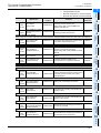
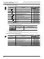
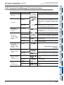
1. DESIGN PRECAUTIONS
Reference
• Provide a safety circuit on the outside of the PLC so that the whole system operates to ensure the
safety even when external power supply trouble or PLC failure occurs.
Otherwise, malfunctions or output failures may result in an accident.
1) An emergency stop circuit, a protection circuit, an interlock circuit for opposite movements,
such as normal and reverse rotations, and an interlock circuit for preventing damage to the
machine at the upper and lower positioning limits should be configured on the outside of the
PLC.
2) When the PLC CPU detects an error, such as a watchdog timer error, during self-diagnosis, all
outputs are turned off. When an error that cannot be detected by the PLC CPU occurs in an
input/output control block, output control may be disabled.
Design external circuits and mechanisms to ensure safe operations of the machine in such a
case.
3) The output current of the 24V DC service power supply varies depending on the model and the
absence/presence of extension blocks. If overload is applied, the voltage automatically drops,
inputs in the PLC are disabled, and all outputs are turned off.
Design external circuits and mechanisms to ensure safe operations of the machine in such a
case.
4) When some sort of error occurs in a relay, triac or transistor of the output unit, output may be
kept on or off.
For output signals that may lead to serious accidents, design external circuits and mechanisms
to ensure safe operations of the machine in such cases.
121
145
162
203
221
260
283
322
404
Reference
• Do not bundle the control line together with the main circuit or power line. Do not lay the control
line near them.As a rule, lay the control line at least 100mm(3.94") or more away from the main
circuit or power line.
Noise may cause malfunctions.
• Install in a manner which prevents excessive force from being applied to the connectors for
peripheral device connections.
Failure to do so may result in wire breakage or failure of the PLC.
(1)
121
145
162
203
221
260
283
322
404
Safety Precautions
(Read these precautions before use.)
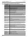
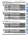
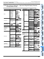
2. INSTALLATION PRECAUTIONS
Reference
• Make sure to cut off all phases of the power supply externally before starting the installation or
wiring work.
Failure to do so may cause electric shock.
121
404
Reference
• Use the product in the environment within the generic specifications described in section 4.1 of this
manual.
Never use the product in areas with dust, oily smoke, conductive dusts, corrosive gas (salt air, Cl2,
H2S, SO2 or NO2), flammable gas, vibration or impacts, or expose it to high temperature,
condensation, or wind and rain.
If the product is used in such a place described, electrical shock, fire, malfunctions, damage, or
deterioration may be caused.
• Do not touch the conductive parts of the product directly, thus avoiding failure or malfunctions.
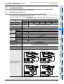
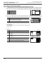
• Install the product securely using a DIN rail or mounting screws.
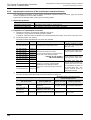
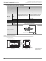
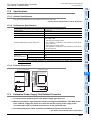
FX2N-10GM, FX2N-20GM, and terminal block
DIN rail only
Main unit, FX2N Series I/O extension unit/block, and FX0N/FX2N/
DIN rail or direct mounting
FX3U Series special extension block/special adapter
• Install the product on a flat surface.
If the mounting surface is rough, undue force will be applied to the PC board, thereby causing
nonconformities.
• Make sure to fix the function extension board with tapping screws for fixation.
Tightening torque: 0.3 to 0.6 N•m
Contact failures may cause malfunctions.
• When drilling screw holes or wiring, cutting chips or wire chips should not enter ventilation slits.
such an accident may cause fire, failures or malfunctions.
• Be sure to remove the dust proof sheet from the PLC's ventilation port when the installation work is
completed. Failure to do so could cause fires, equipment failures, and malfunctions.
• Fit the extension cables, peripheral device connecting cables, input/output cables and battery
connecting cable securely to the designated connectors.
Contact failures may cause malfunctions.
• Fit the display module, memory cassette, and function extension board securely to the designated
connectors.
Contact failures may cause malfunctions.
• Before attaching or detaching the following devices, turn off power.
Failure to do so may cause device failures or malfunctions.
- Peripheral devices, display module , expansion boards and special adapters
- Extension units/blocks and FX Series terminal block
- Battery and memory cassette
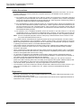
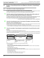
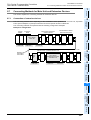
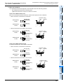
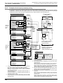
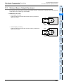
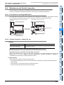
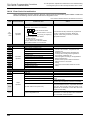
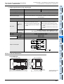
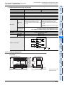
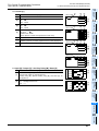
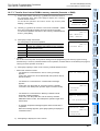
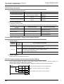
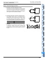
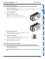
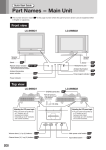
• Connect the memory cassette securely to the prescribed connector.
A poor connection can cause malfunctions.
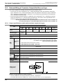
Installing the cassette in a raised or tilted posture can also cause malfunctions.
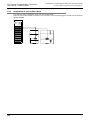
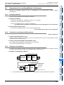
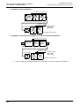
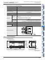
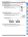
Cross-section drawing (memory cassette installation condition)
Press the 4 corners in approx.
0.4mm(0.02")
Good
Memory
cassette
Bad
Memory
cassette
Raised cassette
posture
Bad
Memory
cassette
Tilted cassette posture
PLC body
(2)
122
405
428
Safety Precautions
(Read these precautions before use.)
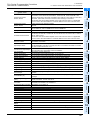
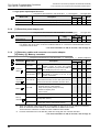
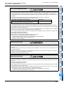
3. WIRING PRECAUTIONS
Reference
• Connect the AC power supply wiring to the dedicated terminals described in this manual.
If an AC power supply is connected to a DC input/output terminal or DC power supply terminal, the
PLC will be burnt out.
• Cut off all phases of the power source externally before installation or wiring work in order to avoid
electric shock or damage of product.
• Make sure to attach the terminal cover offered as an accessory to the product before turning on
the power or starting the operation after installation or wiring work.
Failure to do so may cause electric shock.
122
145
148
151
162
203
221
260
283
405
Reference
• Do not supply power to the [24+] and [24V] terminals (24V DC service power supply) in the main
unit and extension units from the outside.
Such power supply may cause damages to the product.
• Perform class D grounding (grounding resistance: 100 Ω or less) to the grounding terminal in the
main unit and extension units with a 2mm2 or thicker wire.
Do not connect the grounding terminal at the same point as a heavy electrical system (refer to
Section 9.4).
• Connect the DC power supply wiring to the dedicated terminals described in this manual.
If an AC power supply is connected to a DC input/output terminal or DC power supply terminal, the
PLC will be burnt out.
• Do not wire vacant terminals externally.
Doing so may damage the product.
• When drilling screw holes or wiring, cutting chips or wire chips should not enter ventilation slits.
such an accident may cause fire, failures or malfunctions.
• Perform wiring properly to the FX0N/FX2N/FX3U Series extension equipment of the terminal block
type in accordance with the following precautions.
Failure to do so may cause electric shock, short-circuit, wire breakage, or damages to the product.
- The disposal size of the cable end should follow the dimensions described in this manual.
- Tightening torque should be between 0.5 to 0.8 N•m.
• Observe the following items to wire the lines to the European terminal board. Ignorance of the
following items may cause electric shock, short circuit, disconnection, or damage of the product.
- The disposal size of the cable end should follow the dimensions described in this manual.
- Tightening torque should be between 0.22 to 0.25 N•m.
- Twist the end of strand wire and make sure there is no loose wires.
- Do not solder-plate the electric wire ends.
- Do not connect electric wires of unspecified size or beyond the specified number of electric
wires.
- Fix the electric wires so that the terminal block and connected parts of electric wires are not
directly stressed.
• Properly perform wiring to the FX Series terminal blocks following the precautions below in order to
prevent electrical shock, short-circuit, breakage of wire, or damage to the product:
- The disposal size of the cable end should follow the dimensions described in this manual.
- Tightening torque should be between 0.5 to 0.8 N•m.
(3)
123
146
148
163
204
216
217
220
222
261
283
405
414
Safety Precautions
(Read these precautions before use.)
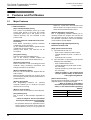
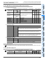
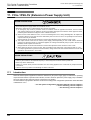
4. STARTUP AND MAINTENANCE PRECAUTIONS
Reference
• Do not touch any terminal while the PLC's power is on.
Doing so may cause electrical shock or malfunctions.
• Before cleaning or retightening terminals, externally cut off all phases of the power supply.
Failure to do so may expose you to shock hazard.
• Correctly connect the battery for memory backup.
Do not charge, disassemble, heat or short-circuit the battery. Do not throw it into the fire.
Doing so may rupture or ignite it.
• Before modifying the program under operation or performing operation for forcible output, running
or stopping, carefully read the manual, and sufficiently ensure the safety.
An operation error may damage the machine or cause accidents.
• Do not change programs in the PLC from two or more peripheral equipment (such as the
programming tool and GOT) at the same time.
Such changes may cause destruction or malfunction of programs in the PLC.
238
346
Reference
• Before attaching or detaching the memory cassette, turn off power. If it is attached or detached
while PLC's power is on, the data in the memory may be destroyed, or the memory cassette may
be damaged.
• Do not disassemble or modify the PLC.
Doing so may cause failures, malfunctions or fire.
For repair, contact your local Mitsubishi Electric distributor.
• Before connecting or disconnecting any extension cable, turn off power.
Failure to do so may cause unit failure or malfunctions.
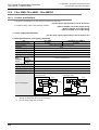
• Before attaching or detaching the following devices, turn off power.
Failure to do so may cause device failure or malfunctions.
- Peripheral devices, display module, expansion boards and special adapters
- Extension blocks, connector conversion adapter and FX Series terminal block
- Battery and memory cassette
238
346
434
5. DISPOSAL PRECAUTIONS
Reference
• Please contact a company certified in the disposal of electronic waste for environmentally safe
recycling and disposal of your device.
238
6. TRANSPORTATION PRECAUTIONS
Reference
• Before transporting the PLC, turn on power to the PLC to check that the BATT LED is off and
check the battery life.
If the PLC is transported with the BATT LED on or the battery exhausted, the backed up data may
be unstable during transportation.
• The PLC is precision equipment. During transportation, avoid impacts larger than that is specified
in the manual (section 4.1) of the PLC main unit. Failure to do so may cause failures in the PLC.
After transportation, check the operations of the PLC.
(4)
238
434
FX3U Series Programmable Controllers
User's Manual - Hardware Edition
FX3U Series Programmable Controllers
User's Manual [Hardware Edition]
Manual number
JY997D16501
Manual revision
B
Date
2/2006
Foreword
This manual contains text, diagrams and explanations which will guide the reader in the correct installation,
safe use and operation of the FX3U Series Programmable Controllers and should be read and understood
before attempting to install or use the unit.
And, store this manual in a safe place so that you can take it out and read it whenever necessary. Always
forward it to the end user.
This manual confers no industrial property rights or any rights of any other kind, nor does it confer any patent
licenses. Mitsubishi Electric Corporation cannot be held responsible for any problems involving industrial property
rights which may occur as a result of using the contents noted in this manual.
© 2005 MITSUBISHI ELECTRIC CORPORATION
1
FX3U Series Programmable Controllers
User's Manual - Hardware Edition
Outline Precautions
• This manual provides information for the use of the FX3U Series Programmable Controllers. The manual
has been written to be used by trained and competent personnel. The definition of such a person or
persons is as follows;
1) Any engineer who is responsible for the planning, design and construction of automatic equipment
using the product associated with this manual should be of a competent nature, trained and qualified
to the local and national standards required to fulfill that role. These engineers should be fully aware of
all aspects of safety with regards to automated equipment.
2) Any commissioning or service engineer must be of a competent nature, trained and qualified to the
local and national standards required to fulfill that job. These engineers should also be trained in the
use and maintenance of the completed product. This includes being completely familiar with all
associated documentation for the said product. All maintenance should be carried out in accordance
with established safety practices.
3) All operators of the completed equipment should be trained to use that product in a safe and
coordinated manner in compliance to established safety practices. The operators should also be
familiar with documentation which is connected with the actual operation of the completed equipment.
Note:
the term 'completed equipment' refers to a third party constructed device which contains or uses
the product associated with this manual
• This product has been manufactured as a general-purpose part for general industries, and has not been
designed or manufactured to be incorporated in a device or system used in purposes related to human life.
• Before using the product for special purposes such as nuclear power, electric power, aerospace, medicine
or passenger movement vehicles, consult with Mitsubishi Electric.
• This product has been manufactured under strict quality control. However when installing the product
where major accidents or losses could occur if the product fails, install appropriate backup or failsafe
functions in the system.
• When combining this product with other products, please confirm the standard and the code, or regulations
with which the user should follow. Moreover, please confirm the compatibility of this product to the system,
machine, and apparatus with which a user is using.
• If in doubt at any stage during the installation of the product, always consult a professional electrical
engineer who is qualified and trained to the local and national standards. If in doubt about the operation or
use, please consult the nearest Mitsubishi Electric distributor.
• Since the examples indicated by this manual, technical bulletin, catalog, etc. are used as a reference,
please use it after confirming the function and safety of the equipment and system. Mitsubishi Electric will
accept no responsibility for actual use of the product based on these illustrative examples.
• This manual content, specification etc. may be changed without a notice for improvement.
• The information in this manual has been carefully checked and is believed to be accurate; however, if you
have noticed a doubtful point, a doubtful error, etc., please contact the nearest Mitsubishi Electric
distributor.
Registration
• Microsoft® and Windows® are either registered trademarks or trademarks of Microsoft Corporation in the
United States and/or other countries.
• The company name and the product name to be described in this manual are the registered trademarks or
trademarks of each company.
2
FX3U Series Programmable Controllers
User's Manual - Hardware Edition
Table of Contents
Table of Contents
SAFETY PRECAUTIONS .................................................................................................... 1
Standards
15
Certification of UL, cUL standards ..................................................................................................... 15
Compliance with EC directive (CE Marking) ...................................................................................... 16
Requirement for Compliance with EMC directive .................................................................................. 16
Requirement for Compliance with LVD directive ................................................................................... 18
Caution for compliance with EC Directive ............................................................................................. 19
1. Introduction
20
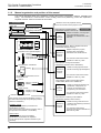
1.1 Introduction of Manuals................................................................................................................ 20
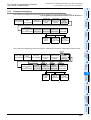
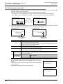
1.1.1 Classification of major components in this manual........................................................................ 20
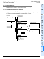
1.1.2 Manual organization and position of this manual .......................................................................... 22
1.1.3 List of manuals .............................................................................................................................. 23
1.2 Generic Names and Abbreviations Used in Manuals.................................................................... 28
2. Features and Part Names
30
2.1 Major Features .............................................................................................................................. 30
2.2 Names and Functions of Parts...................................................................................................... 32
2.2.1 Front Panel .................................................................................................................................... 32
2.2.2 Sides.............................................................................................................................................. 34
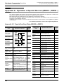
3. Introduction of Products (Compliant with Overseas Standards)
35
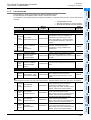
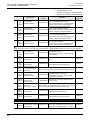
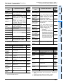
3.1 List of Products (to be Connected) and Interpretation of Model Names ....................................... 35
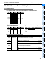
3.1.1 [A] Main units................................................................................................................................. 36
3.1.2 [B] Input/output powered extension units ...................................................................................... 37
3.1.3 [C] Input/output extension blocks .................................................................................................. 38
3.1.4 [D] [E] Special function units/blocks .............................................................................................. 39
3.1.5 [F] Display modules and holder ..................................................................................................... 41
3.1.6 [G] Expansion boards .................................................................................................................... 41
3.1.7 [H] Special adapters ...................................................................................................................... 41
3.1.8 [I] Extension power supply unit...................................................................................................... 42
3.1.9 [J] Extension cables and connector conversion adapter [K] Battery [L] Memory cassettes .......... 42
3.1.10 [M] FX Series terminal blocks (cables and connectors) .............................................................. 43
3.1.11 [N] Remote I/O............................................................................................................................. 43
3.1.12 [O] Power supply unit .................................................................................................................. 43
3.2 Connector Types and Cables for Program Communication.......................................................... 44
3.2.1 Programming tool .......................................................................................................................... 45
3.2.2 Communication cables .................................................................................................................. 45
3.2.3 Converters and interface ............................................................................................................... 46
3
FX3U Series Programmable Controllers
User's Manual - Hardware Edition
4. Specifications, External Dimensions and Terminal Layout (Main Units)
Table of Contents
47
4.1 Generic Specifications .................................................................................................................. 47
4.1.1 Dielectric withstand voltage test and insulation resistance test..................................................... 48
4.2 Power Supply Specifications......................................................................................................... 49
4.2.1 AC Power Supply Type ................................................................................................................. 49
4.2.2 DC Power Supply Type ................................................................................................................. 50
4.3 Input Specifications ....................................................................................................................... 51
4.3.1 24V DC Input (sink/source) ........................................................................................................... 51
4.4 Output Specifications .................................................................................................................... 52
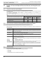
4.4.1
4.4.2
4.4.3
4.4.4
Relay output .................................................................................................................................. 52
Product life of relay contacts ......................................................................................................... 53
Transistor output (sink type) .......................................................................................................... 53
Transistor output (source type)...................................................................................................... 54
4.5 Performance Specifications .......................................................................................................... 55
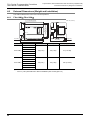
4.6 External Dimensions (Weight and Installation) ............................................................................. 58
4.6.1 FX3U-16M , FX3U-32M ............................................................................................................ 58
4.6.2 FX3U-48M , FX3U-64M , FX3U-80M , FX3U-128M .............................................................. 59
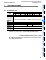
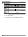
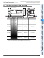
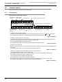
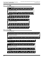
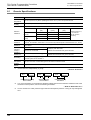
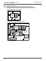
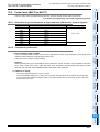
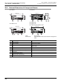
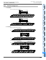
4.7 Terminal Layout ............................................................................................................................ 60
4.7.1
4.7.2
4.7.3
4.7.4
4.7.5
4.7.6
4.7.7
Interpretation ................................................................................................................................. 60
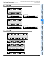
FX3U-16M ................................................................................................................................... 61
FX3U-32M ................................................................................................................................... 61
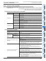
FX3U-48M ................................................................................................................................... 62
FX3U-64M ................................................................................................................................... 62
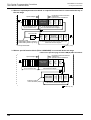
FX3U-80M ................................................................................................................................... 63
FX3U-128M ................................................................................................................................. 64
5. Version Information and Peripheral Equipment Connectability
65
5.1 Version Upgrade History ............................................................................................................... 65
5.1.1 Version check method ................................................................................................................... 65
5.1.2 How to look at manufacturer’s serial number ................................................................................ 65
5.1.3 Version upgrade history................................................................................................................. 65
5.2 Programming Tool Applicability..................................................................................................... 66
5.2.1
5.2.2
5.2.3
5.2.4
Applicable versions of programming tool....................................................................................... 66
In the case of programming tool (version) not applicable.............................................................. 66
Program transfer speed and programming tool............................................................................. 66
Cautions on write during RUN ....................................................................................................... 67
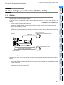
5.3 Cautions on using transparent function by way of USB in GOT1000 Series ................................ 69
5.4 Cautions on using transparent port (2-port) function of GOT-F900 Series ................................... 70
5.5 Other Peripheral Equipment Applicability...................................................................................... 71
5.5.1 Applicable products and versions.................................................................................................. 71
5.5.2 In the case of peripheral equipment not applicable ....................................................................... 71
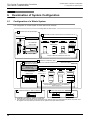
6. Examination of System Configuration
72
6.1 Configuration of a Whole System.................................................................................................. 72
6.1.1 List of system components ............................................................................................................ 73
6.1.2 System configuration with special adapters .................................................................................. 75
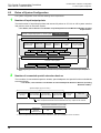
6.2 Rules of System Configuration...................................................................................................... 76
6.3 Number of Input/Output Points and Maximum Number of Input/Output Points ............................ 78
6.3.1 Calculation of number of input/output points ................................................................................. 78
6.3.2 Maximum number of input/output points when CC-Link master is used ....................................... 80
6.3.3 Maximum number of input/output points when AS-i master is used.............................................. 81
6.4 Number of Connected Special Extension Devices (Including Extension Cable)........................... 82
6.4.1 Expansion board and special adapter ........................................................................................... 82
6.4.2 Special function units/blocks, High-speed input/output special adapter........................................ 82
6.4.3 Extension cable ............................................................................................................................. 82
4
FX3U Series Programmable Controllers
User's Manual - Hardware Edition
Table of Contents
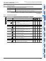
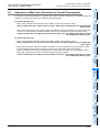
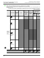
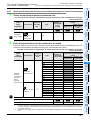
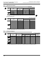
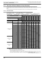
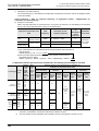
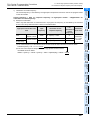
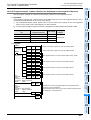
6.5 Expansion of Main Unit (Calculation of Current Consumption)..................................................... 83
6.5.1 Quick reference matrix - when only input/output devices are added (AC Power Type) ................ 84
6.5.2 When special extension devices are also added
[calculation of current consumption] (AC Power Type)............................................................. 85
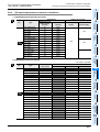
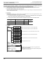
6.5.3 Quick reference matrix [when only input/output devices are added] (DC Power Type) ................ 88
6.5.4 When special extension devices are also added
[calculation of current consumption] (DC Power Type) ............................................................ 89
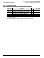
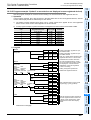
6.6 Expansion of FX2N Series I/O Powered Extension Unit (Calculation of Current Consumption)... 92
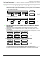
6.6.1 Quick reference matrix (when only input/output devices are added)............................................. 92
6.6.2 When special extension devices are also added (calculation of current consumption)................. 95
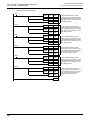
6.7 Expansion of Extension Power Supply Unit (FX3U-1PSU-5V)...................................................... 97
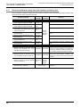
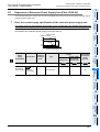
6.8 Number of Input/Output (Occupied) Points and Current Consumption....................................... 100
6.8.1
6.8.2
6.8.3
6.8.4
6.8.5
6.8.6
6.8.7
[A] Main units............................................................................................................................... 101
[B] Expansion boards .................................................................................................................. 102
[C] Special adapters .................................................................................................................... 102
[D] Input/output powered extension units/blocks ......................................................................... 103
[E] Special extension devices...................................................................................................... 104
[G] Display module ...................................................................................................................... 105
[H] Extension power supply unit .................................................................................................. 105
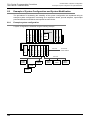
6.9 Example of System Configuration and System Modification....................................................... 106
6.9.1 Example system configuration..................................................................................................... 106
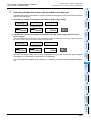
6.9.2 Expansion of main unit ................................................................................................................ 107
6.9.3 Re-examination of suitability for configuration............................................................................. 110
7. Assignment of Input/Output Numbers (X/Y) and Unit Numbers
115
7.1 Assignment of Input/Output Numbers (X/Y)................................................................................ 115
7.1.1 Concept of assigning ................................................................................................................... 115
7.1.2 Example of assigning .................................................................................................................. 116
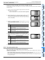
7.1.3 Application of I/O number label ................................................................................................... 117
7.2 Unit Numbers of Special Function Units/Blocks.......................................................................... 118
7.2.1 Concept of assigning ................................................................................................................... 118
7.2.2 Example of assigning .................................................................................................................. 119
7.2.3 Application of unit number labels................................................................................................. 120
8. Installation In Enclosure
121
8.1 Generic Specifications ................................................................................................................ 124
8.2 Installation location...................................................................................................................... 125
8.2.1 Installation location in enclosure.................................................................................................. 125
8.2.2 Spaces in enclosure .................................................................................................................... 126
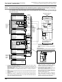
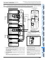
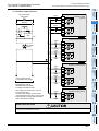
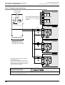
8.3 Layout in Enclosure..................................................................................................................... 127
8.3.1 1-stage layout .............................................................................................................................. 127
8.3.2 2-stage layout .............................................................................................................................. 127
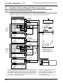
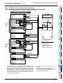
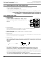
8.4 Examination for Installing Method in Enclosure .......................................................................... 129
8.4.1 Installing methods........................................................................................................................ 129
8.4.2 Cautions in examining installing method ..................................................................................... 129
8.4.3 Examples of installation............................................................................................................... 129
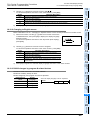
8.5 Procedures for Installing on and Detaching from DIN Rail.......................................................... 131
8.5.1
8.5.2
8.5.3
8.5.4
Preparation for installation........................................................................................................... 131
Installation of main unit................................................................................................................ 132
Installation of input/output powered extension unit/block and special function unit/block ........... 133
Removal of main unit................................................................................................................... 133
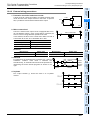
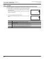
8.6 Procedures for Installing Directly (with M4 Screws).................................................................... 135
8.6.1
8.6.2
8.6.3
8.6.4
Hole pitches for direct mounting .................................................................................................. 135
Example of mounting hole pitches............................................................................................... 137
Installation of main unit................................................................................................................ 138
Installation of input/output powered extension unit/block and special function unit/block ........... 138
5
FX3U Series Programmable Controllers
User's Manual - Hardware Edition
Table of Contents
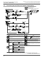
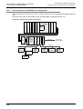
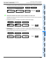
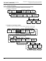
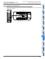
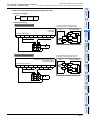
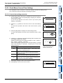
8.7 Connecting Methods for Main Unit and Extension Devices ........................................................ 139
8.7.1
8.7.2
8.7.3
8.7.4
8.7.5
8.7.6
8.7.7
8.7.8
Connection of extension devices................................................................................................. 139
Connecting method A - connection of expansion board.............................................................. 140
Connecting method B - connection of special adapter ................................................................ 141
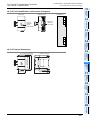
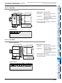
Connecting method C - connection of powered extension unit/block to main unit ...................... 141
Connecting method D - connection of powered extension units/blocks ...................................... 142
Connecting method E - connection of extension cable and FX2N-CNV-BC................................ 143
Connecting method F - connection of input/output powered extension unit................................ 143
Connecting method G connection of extension block to input/output powered extension unit................................... 144
9. Preparation for Wiring and Power Supply Wiring Procedures
145
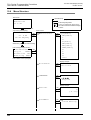
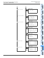
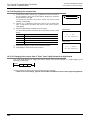
9.1 Preparation for Wiring ................................................................................................................. 147
9.1.1 Wiring procedures ....................................................................................................................... 147
9.2 Cable Connecting Procedures .................................................................................................... 148
9.2.1 Input/output terminal block (power supply and input/output wiring)............................................. 148
9.2.2 Input/output connectors (FX2N input/output extension blocks) ................................................... 150
9.2.3 Terminal block (for europe) [expansion board and special adapters].......................................... 151
9.3 Power Supply Specifications....................................................................................................... 152
9.3.1 AC Power Supply Type ............................................................................................................... 152
9.3.2 DC Power Supply Type .............................................................................................................. 153
9.4 Grounding ................................................................................................................................... 154
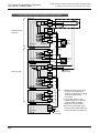
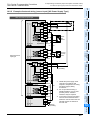
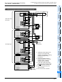
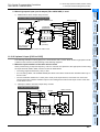
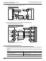
9.5 Examples of External Wiring [AC Power Supply Type]............................................................... 155
9.5.1
9.5.2
9.5.3
9.5.4
9.5.5
Example of input/output wiring with 24V DC service power supply............................................. 155
Example of sink input [-common] wiring ...................................................................................... 156
Example of source input [+common] wiring................................................................................. 157
An external wiring example for the extension power supply unit (sink input [-common]) ............ 158
An external wiring example for the extension power supply unit (source input [+common]) ....... 159
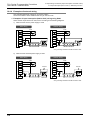
9.6 Examples of External Wiring [DC Power Supply Type]............................................................... 160
9.6.1 Example of sink input [-common] wiring ...................................................................................... 160
9.6.2 Example of source input [+common] wiring................................................................................. 161
10. Input Wiring Procedures (Input Interruption and Pulse Catch)
162
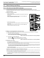
10.1 Before Starting Input Wiring ...................................................................................................... 164
10.1.1 Sink and source input (24V DC input type) ............................................................................... 164
10.2 24V DC Input Type (Common to Sink/Source Input) ................................................................ 165
10.2.1
10.2.2
10.2.3
10.2.4
10.2.5
10.2.6
10.2.7
Input specifications (main unit) .................................................................................................. 165
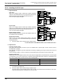
Handling of 24V DC input .......................................................................................................... 166
Instructions for connecting input devices................................................................................... 167
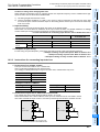
Examples of external wiring (sink input) [AC Power Supply Type]............................................ 169
Example of external wiring (source input) [AC Power Supply Type] ......................................... 171
Examples of external wiring (sink input) [DC power supply type].............................................. 172
Examle of external wiring (source input) [DC Power Supply Type] ........................................... 174
10.3 100V AC Input (Except Main Unit) ............................................................................................ 175
10.3.1 Input specifications .................................................................................................................... 175
10.3.2 Handling of 100V AC Input ........................................................................................................ 175
10.3.3 Example of external wiring ........................................................................................................ 176
10.4 Input Interruption (I00
10.4.1
10.4.2
10.4.3
10.4.4
to I50 ) - With Delay Function........................................................... 177
Allocation of pointers to input numbers (input signal ON/OFF duration) ................................... 177
Input interruption delay function ................................................................................................ 177
Cautions for input interruption ................................................................................................... 177
Examples of external wiring....................................................................................................... 178
10.5 Pulse Catch (M8170 to M8177) ................................................................................................ 179
10.5.1 Allocation of special memories to Iinput numbers (ON duration of input signals) ..................... 179
10.5.2 Cautions for pulse catch ............................................................................................................ 179
10.5.3 Examples of external wiring....................................................................................................... 180
6
FX3U Series Programmable Controllers
User's Manual - Hardware Edition
11. Use of High-speed Counters (C235 to C255)
Table of Contents
181
11.1 Outline....................................................................................................................................... 181
11.2 Input Specifications ................................................................................................................... 182
11.2.1 High-speed input special adapter (FX3U-4HSX-ADP)............................................................... 182
11.2.2 Cautions in connecting mating device ....................................................................................... 182
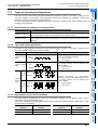
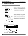
11.3 Types of Counting and Operations ........................................................................................... 183
11.3.1 Classification according to counting method ............................................................................. 183
11.3.2 Types and input signal forms..................................................................................................... 183
11.3.3 High-speed counter device notations ........................................................................................ 183
11.4 List of Device Numbers and Functions ..................................................................................... 184
11.5 Allocation of Device Numbers to Input Numbers ...................................................................... 186
11.5.1 Allocation table .......................................................................................................................... 186
11.5.2 Inhibition of redundant use of input numbers ............................................................................ 187
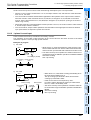
11.6 Handling of High-speed Counters ............................................................................................. 188
11.6.1 1-phase 1-count input................................................................................................................ 188
11.6.2 1-phase 2-count input................................................................................................................ 189
11.6.3 2-phase 2-count input................................................................................................................ 190
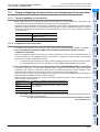
11.7 Timing of Updating of Current Value and Comparison of Current Value .................................. 191
11.7.1 Timing of updating of current value ........................................................................................... 191
11.7.2 Comparison of current value ..................................................................................................... 191
11.8 Conditions for Hardware Counter to be Handled as Software Counter .................................... 192
11.8.1 Conditions under which counters are handled as software counters ........................................ 192
11.8.2 Method of confirming operation status of counters.................................................................... 192
11.9 Calculation of Response Frequency and Overall Frequency.................................................... 193
11.9.1 Response frequencies of hardware counters ............................................................................ 193
11.9.2 Response frequencies and overall frequency of software counters .......................................... 193
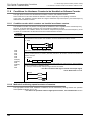
11.10 Examples of External Wiring (Rotary Encoder)....................................................................... 196
11.10.1 1-phase 1-input [C235 to C245] .............................................................................................. 196
11.10.2 2-phase 2-input [C251 to C255] .............................................................................................. 197
11.10.3 Cautions for the other side device ........................................................................................... 198
11.11 Related Devices and Function Switching Procedures ............................................................ 199
11.11.1
11.11.2
11.11.3
11.11.4
Related devices ....................................................................................................................... 199
[Function switching] switching of logic of external reset input signal....................................... 201
[Function switching] switching of allocation and functions of input terminals .......................... 201
[Function switching] procedures for using 2-phase 2-count input counters
C251 to C255 in 4 edge count mode ...................................................................................... 202
12. Output Wiring Procedures
203
12.1 Sink and Source Output (Transistor)......................................................................................... 205
12.2 External Wiring for Relay Output............................................................................................... 206
12.2.1
12.2.2
12.2.3
12.2.4
12.2.5
Output specifications (main unit) ............................................................................................... 206
Product life of relay contacts ..................................................................................................... 207
Handling of relay output............................................................................................................. 207
Cautions on external wiring ....................................................................................................... 208
Example of external wiring ........................................................................................................ 209
12.3 External Wiring of Transistor Output (Sink/Source) Type ......................................................... 210
12.3.1
12.3.2
12.3.3
12.3.4
12.3.5
Output specifications (main unit) transistor output (sink type)................................................... 210
Output specifications (main unit) transistor output (source type) .............................................. 211
Handling of transistor output...................................................................................................... 212
External wiring precautions ....................................................................................................... 214
Example of external wiring ........................................................................................................ 216
12.4 External Wiring for Triac (SSR) Output Type ............................................................................ 218
12.4.1 Handling of triac output.............................................................................................................. 218
12.4.2 External wiring precautions ....................................................................................................... 219
12.4.3 Example of external wiring ........................................................................................................ 220
7
FX3U Series Programmable Controllers
User's Manual - Hardware Edition
13. Examples of Wiring for Various Uses
Table of Contents
221
13.1 Notes about Examples of Wiring............................................................................................... 222
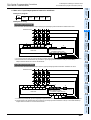
13.2 Digital Switch [DSW Instructions (FNC72)/BIN Instructions (FNC19)]...................................... 223
13.2.1 When DSW instructions are used.............................................................................................. 223
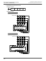
13.2.2 When BIN instructions are used ................................................................................................ 226
13.3
13.4
13.5
13.6
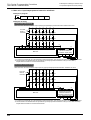
Ten Key Input [TKY Instructions (FNC70)]................................................................................ 227
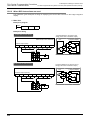
Hexadecimal Input [HKY Instructions (FNC71)]........................................................................ 228
Input Matrix [MTR Instructions (FNC52)] .................................................................................. 231
Seven Segment with Latch [SEGL Instructions (FNC74)/BCD Instructions (FNC18)] .............. 234
13.6.1 When SEGL instructions are used ............................................................................................ 234
13.6.2 When BCD instructions are used .............................................................................................. 236
14. Test Operation, Adjustment, Maintenance and Troubleshooting
238
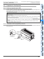
14.1 Preparation for Test Operation.................................................................................................. 239
14.1.1 Preliminary inspection [power OFF] .......................................................................................... 239
14.1.2 Connection to built-in programming connector.......................................................................... 239
14.1.3 Writing of program and program check [power ON and PLC stopped] ..................................... 240
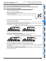
14.2 Running and Stopping Procedures [Power ON]........................................................................ 241
14.2.1 Methods of running and stopping .............................................................................................. 241
14.2.2 Use of several running/stopping methods ................................................................................. 242
14.3 Operation and Test [Power ON and PLC Running] .................................................................. 243
14.3.1 Self-diagnostic function ............................................................................................................. 243
14.3.2 Test functions ............................................................................................................................ 243
14.3.3 Program modification function ................................................................................................... 244
14.4 Maintenance and Periodic Inspection ....................................................................................... 245
14.4.1
14.4.2
14.4.3
14.4.4
Procedures for checking model name ....................................................................................... 245
Periodic inspection - battery life, etc.......................................................................................... 245
Maintenance - product life of relay contacts ............................................................................. 246
Procedures for replacing battery ............................................................................................... 246
14.5 Troubleshooting with LEDs ....................................................................................................... 247
14.5.1 POWER LED [on/flashing/off].................................................................................................... 247
14.5.2 BATT LED [on/off] ..................................................................................................................... 247
14.5.3 ERROR LED [on/flashing/off] .................................................................................................... 248
14.6 Judgment by Error Codes and Representation of Error Codes ................................................ 249
14.6.1
14.6.2
14.6.3
14.6.4
Operation and check on display module (FX3U-7DM) .............................................................. 249
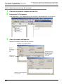
Operation and check by GX developer...................................................................................... 250
Representation of errors............................................................................................................ 251
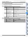
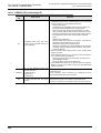
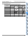
Error Code List and Action ........................................................................................................ 252
14.7 Troubleshooting ....................................................................................................................... 258
14.7.1 Output does not operate (main unit and input/output extension blocks) ................................... 258
14.7.2 24V DC input does not operate (main unit and input/output extension blocks)......................... 258
14.7.3 Cautions in registering keyword ................................................................................................ 259
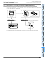
15. FX2N-32/48E*-* (Input/Output Powered Extension Units)
260
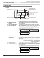
15.1 Outline....................................................................................................................................... 262
15.1.1 Product configuration................................................................................................................. 262
15.1.2 Product list................................................................................................................................. 262
15.2 Power Supply Specifications (Power Supply Input/24V DC Service Power Supply) ................ 263
15.2.1 Weight, accessories, etc............................................................................................................ 263
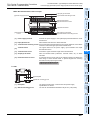
15.2.2 Part names ................................................................................................................................ 264
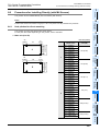
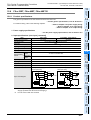
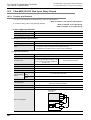
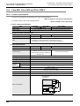
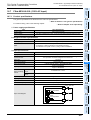
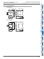
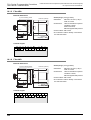
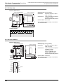
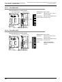
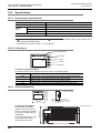
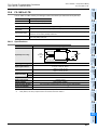
15.3 FX2N-32ER-ES/UL, FX2N-48ER-ES/UL, FX2N-48ER-DS ........................................................ 266
15.3.1 Product specifications................................................................................................................ 266
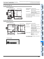
15.3.2 External dimensions .................................................................................................................. 267
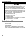
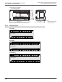
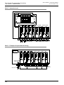
15.3.3 Terminal layout .......................................................................................................................... 268
8
FX3U Series Programmable Controllers
User's Manual - Hardware Edition
Table of Contents
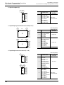
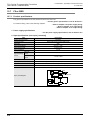
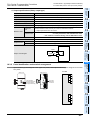
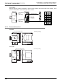
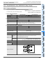
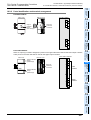
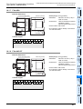
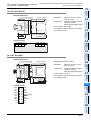
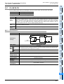
15.4 FX2N-32ET-ESS/UL, FX2N-48ET-ESS/UL, FX2N-48ET-DSS................................................... 269
15.4.1 Product specifications................................................................................................................ 269
15.4.2 External dimensions .................................................................................................................. 270
15.4.3 Terminal layout .......................................................................................................................... 271
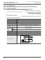
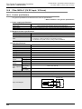
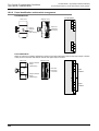
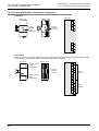
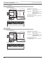
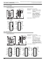
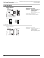
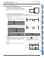
15.5 FX2N-32ER, FX2N-48ER, FX2N-48ER-D ................................................................................. 272
15.5.1 Product specifications................................................................................................................ 272
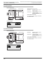
15.5.2 External dimensions .................................................................................................................. 273
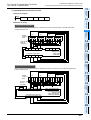
15.5.3 Terminal layout .......................................................................................................................... 274
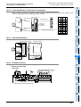
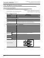
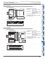
15.6 FX2N-32ET, FX2N-48ET, FX2N-48ET-D.................................................................................... 275
15.6.1 Product specifications................................................................................................................ 275
15.6.2 External dimensions .................................................................................................................. 276
15.6.3 Terminal layout .......................................................................................................................... 277
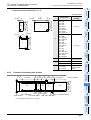
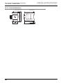
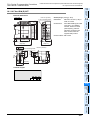
15.7 FX2N-32ES................................................................................................................................ 278
15.7.1 Product specifications................................................................................................................ 278
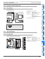
15.7.2 External dimensions .................................................................................................................. 279
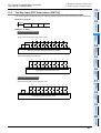
15.7.3 Terminal layout .......................................................................................................................... 279
15.8 FX2N-48ER-UA1/UL.................................................................................................................. 280
15.8.1 Product specifications................................................................................................................ 280
15.8.2 External dimensions .................................................................................................................. 281
15.8.3 Terminal layout .......................................................................................................................... 282
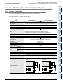
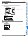
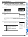
16. FX2N-8/16E*-*(Input/Output Extension Blocks)
283
16.1 Outline....................................................................................................................................... 284
16.1.1 Product type .............................................................................................................................. 284
16.1.2 List of products .......................................................................................................................... 285
16.2 FX2N-8ER-ES/UL (24V DC Sink/Source Input, Relay Output) ................................................. 287
16.2.1 Product specifications................................................................................................................ 287
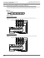
16.2.2 Parts identification and terminal arrangement ........................................................................... 288
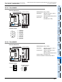
16.2.3 External dimensions .................................................................................................................. 289
16.3 FX2N-8ER (24V DC Sink Input, Relay Output) ......................................................................... 290
16.3.1 Product specifications................................................................................................................ 290
16.3.2 Parts identification and terminal arrangement ........................................................................... 291
16.3.3 External dimensions .................................................................................................................. 292
16.4 FX2N-8EX-ES/UL, FX2N-16EX-ES/UL (24V DC Sink/Source Input) ........................................ 293
16.4.1 Product specifications................................................................................................................ 293
16.4.2 Parts identification and terminal arrangement ........................................................................... 294
16.4.3 External dimensions .................................................................................................................. 295
16.5 FX2N-8EX, FX2N-16EX and FX2N-16EX-C .............................................................................. 296
16.5.1 Product specifications................................................................................................................ 296
16.5.2 Parts identification and terminal arrangement ........................................................................... 297
16.5.3 External dimensions .................................................................................................................. 298
16.6 FX2N-16EXL-C (5V DC Input: 16 Points).................................................................................. 300
16.6.1
16.6.2
16.6.3
16.6.4
Product specifications................................................................................................................ 300
Parts identification and terminal arrangement ........................................................................... 301
External dimensions .................................................................................................................. 301
Example of wiring ...................................................................................................................... 301
16.7 FX2N-8EX-UA1/UL (100V AC Input)......................................................................................... 303
16.7.1 Product specifications................................................................................................................ 303
16.7.2 Parts identification and terminal arrangment ............................................................................. 304
16.7.3 External dimensions .................................................................................................................. 304
16.8 FX2N-8EYR-ES/UL, FX2N-16EYR-ES/UL (Relay Output) ........................................................ 305
16.8.1 Product specifications................................................................................................................ 305
16.8.2 Parts identification and terminal arrangement ........................................................................... 306
16.8.3 External dimensions .................................................................................................................. 307
16.9 FX2N-8EYT-ESS/UL, FX2N-16EYT-ESS/UL (Transistor Output) ............................................. 308
16.9.1 Product specifications................................................................................................................ 308
16.9.2 Parts identification and terminal arrangement ........................................................................... 309
16.9.3 External dimensions .................................................................................................................. 310
9
FX3U Series Programmable Controllers
User's Manual - Hardware Edition
Table of Contents
16.10 FX2N-8EYR, FX2N-16EYR (Relay Output) ............................................................................. 311
16.10.1 Product specifications.............................................................................................................. 311
16.10.2 Parts identification and terminal arrangement ......................................................................... 312
16.10.3 External dimensions ................................................................................................................ 313
16.11 FX2N-8EYT, FX2N-16EYT and FX2N-16EYT-C (Transistor Output) ...................................... 314
16.11.1 Product specifications.............................................................................................................. 314
16.11.2 Parts identification and terminal arrangement ......................................................................... 315
16.11.3 External dimensions ................................................................................................................ 316
16.12 FX2N-8EYT-H (Transistor Output) .......................................................................................... 318
16.12.1 Product specifications.............................................................................................................. 318
16.12.2 Parts identification and terminal arrangment ........................................................................... 319
16.12.3 External dimensions ................................................................................................................ 319
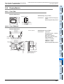
16.13 FX2N-16EYS (Triac Output: 16 Points)................................................................................... 320
16.13.1 Product specifications.............................................................................................................. 320
16.13.2 Parts identification and terminal arrangement ......................................................................... 321
16.13.3 External dimensions ................................................................................................................ 321
17. FX3U-1PSU-5V (Extension Power Supply Unit)
322
17.1 Introduction ....................................................................................................................................... 322
17.2 Specifications ................................................................................................................................... 323
17.2.1 Generic Specifications............................................................................................................... 323
17.2.2 Performance Specifications....................................................................................................... 323
17.2.3 External Dimensions.................................................................................................................. 323
17.3 Extension Power Supply Unit Related Precaution ........................................................................ 323
18. Other Extension Devices and Optional Units
(External Dimensions and Terminal Arrangement)
324
18.1 Special Function Units/Blocks................................................................................................... 324
18.1.1 FX0N-3A .................................................................................................................................... 324
18.1.2 FX2N-2AD ................................................................................................................................. 324
18.1.3 FX2N-2DA.................................................................................................................................. 325
18.1.4 FX3U-4AD.................................................................................................................................. 325
18.1.5 FX3U-4DA.................................................................................................................................. 326
18.1.6 FX2N-4AD.................................................................................................................................. 326
18.1.7 FX2N-4DA.................................................................................................................................. 327
18.1.8 FX2N-4AD-PT ............................................................................................................................ 327
18.1.9 FX2N-4AD-TC............................................................................................................................ 328
18.1.10 FX2N-5A .................................................................................................................................. 328
18.1.11 FX2N-2LC ................................................................................................................................ 329
18.1.12 FX2N-8AD................................................................................................................................ 329
18.1.13 FX2N-1HC ............................................................................................................................... 330
18.1.14 FX3U-20SSC-H ....................................................................................................................... 330
18.1.15 FX2N-1PG(-E) ......................................................................................................................... 331
18.1.16 FX2N-10PG ............................................................................................................................. 331
18.1.17 FX2N-10GM............................................................................................................................. 332
18.1.18 FX2N-20GM............................................................................................................................. 332
18.1.19 FX2N-1RM(-E)-SET................................................................................................................. 333
18.1.20 FX2N-232IF ............................................................................................................................. 334
18.1.21 FX2N-32ASI-M......................................................................................................................... 334
18.1.22 FX2N-64CL-M.......................................................................................................................... 335
18.1.23 FX2N-16CCL-M ....................................................................................................................... 335
18.1.24 FX2N-32CCL ........................................................................................................................... 336
18.1.25 FX2N-16LNK-M ....................................................................................................................... 336
18.2 Extension Power Supply Unit.................................................................................................... 337
18.2.1 FX3U-1PSU-5V.......................................................................................................................... 337
10
FX3U Series Programmable Controllers
User's Manual - Hardware Edition
Table of Contents
18.3 Special Adapters ....................................................................................................................... 337
18.3.1
18.3.2
18.3.3
18.3.4
18.3.5
18.3.6
18.3.7
18.3.8
FX3U-4AD-ADP ......................................................................................................................... 337
FX3U-4DA-ADP ......................................................................................................................... 338
FX3U-4AD-PT-ADP ................................................................................................................... 338
FX3U-4AD-TC-ADP ................................................................................................................... 338
FX3U-232ADP ........................................................................................................................... 339
FX3U-485ADP ........................................................................................................................... 339
FX3U-4HSX-ADP....................................................................................................................... 340
FX3U-2HSY-ADP....................................................................................................................... 340
18.4 Expansion Board....................................................................................................................... 341
18.4.1
18.4.2
18.4.3
18.4.4
18.4.5
FX3U-USB-BD ........................................................................................................................... 341
FX3U-232-BD ............................................................................................................................ 341
FX3U-422-BD ............................................................................................................................ 341
FX3U-485-BD ............................................................................................................................ 342
FX3U-CNV-BD ........................................................................................................................... 342
18.5 Power Supply ............................................................................................................................ 343
18.5.1 FX2N-20PSU ............................................................................................................................. 343
18.6 Connector Conversion Adapter................................................................................................. 343
18.6.1 FX2N-CNV-BC ........................................................................................................................... 343
18.7 Interface Module ....................................................................................................................... 344
18.7.1 FX-232AWC-H........................................................................................................................... 344
18.7.2 FX-USB-AW .............................................................................................................................. 344
18.8 Display Module.......................................................................................................................... 345
18.8.1 FX3U-7DM................................................................................................................................. 345
18.8.2 FX3U-7DM-HLD ........................................................................................................................ 345
19. FX3U-7DM (Display Module)
346
19.1 Description of Products (Introduction of Related Products) ...................................................... 347
19.2 Specifications ............................................................................................................................ 348
19.2.1 Display/switch specifications ..................................................................................................... 348
19.2.2 Parts layout................................................................................................................................ 348
19.2.3 External dimensions .................................................................................................................. 348
19.3 Installation and Removal........................................................................................................... 349
19.4 Summary of Functions .............................................................................................................. 350
19.5 Procedure for Accessing the Menu Screen from the Title Screen ............................................ 351
19.5.1 Title screen ................................................................................................................................ 351
19.5.2 Top screen (time display) .......................................................................................................... 351
19.5.3 Menu screen.............................................................................................................................. 351
19.6 Menu Structure.......................................................................................................................... 352
19.7 Monitor/Test Mode [Excluding User-Registered Devices]......................................................... 354
19.7.1
19.7.2
19.7.3
19.7.4
19.7.5
Relevant devices ....................................................................................................................... 354
Monitor mode operation............................................................................................................. 355
Monitor screen & status display................................................................................................. 356
Test mode operation.................................................................................................................. 358
Test mode operation notes........................................................................................................ 361
19.8 Monitor/Test Mode [User-Registered Devices] ......................................................................... 362
19.8.1 Monitor mode operation............................................................................................................. 362
19.8.2 Test mode operation.................................................................................................................. 363
19.9 Error Check ............................................................................................................................... 363
19.10 LANGUAGE (Menu Display Language Setting)...................................................................... 364
19.10.1 Changing to Japanese menus................................................................................................. 364
19.10.2 Changing to English menus..................................................................................................... 365
19.10.3 D8302 changes by program & related devices........................................................................ 365
19.11 Contrast................................................................................................................................... 366
19.12 Clock Menu (Current Time Setting)......................................................................................... 367
19.12.1 Current time setting procedure ................................................................................................ 367
19.12.2 Displaying the current time ...................................................................................................... 368
19.12.3 Changing the current time’s "Year" from 2-digit format to 4-digit format ................................. 368
11
FX3U Series Programmable Controllers
User's Manual - Hardware Edition
Table of Contents
19.13 Entrycodes .............................................................................................................................. 369
19.13.1
19.13.2
19.13.3
19.13.4
19.13.5
19.13.6
Entry code types & levels ........................................................................................................ 369
Level-specific restrictions screen list ....................................................................................... 370
Entry code storage .................................................................................................................. 371
Screens requiring entry codes for access ............................................................................... 371
Canceling an entry code.......................................................................................................... 372
Enabling an entry code............................................................................................................ 373
19.14 Device All-Clear ...................................................................................................................... 373
19.14.1 Device all-clear operation ........................................................................................................ 373
19.15 PLC Status .............................................................................................................................. 374
19.15.1 Display operation..................................................................................................................... 374
19.15.2 PLC status display items ......................................................................................................... 375
19.16 Scan Time (Scan Time Display).............................................................................................. 376
19.16.1 Scan time display operation .................................................................................................... 376
19.17 Cassette (Memory Cassette Transfers) .................................................................................. 376
19.17.1 Transfer from internal RAM to memory cassette (Cassette <- RAM) ...................................... 377
19.17.2 Transfer from memory cassette to internal RAM (Cassette -> RAM) ...................................... 378
19.17.3 Memory cassette & internal RAM consistency check (Cassette : RAM) ................................. 379
19.18 System Information (Restrictions From PLC).......................................................................... 380
19.18.1 System information list ............................................................................................................ 380
19.18.2 System information setting programexample .......................................................................... 381
19.19 User (User-Registered Device Setting)................................................................................... 382
19.19.1
19.19.2
19.19.3
19.19.4
19.19.5
System information - user-registered device setting ............................................................... 382
Precaution when setting 3 or fewer devices ............................................................................ 382
Program example 1 (when 4 devices are displayed as user-registered devices) ................... 383
Program example 2 (when 3 or fewer devices are displayed as user-registered devices) ..... 384
Program example 3 (when 5 or more devices are displayed as user-registered devices) ...... 385
19.20 Operation Button ON/OFF Information ................................................................................... 387
19.20.1 Various applications ................................................................................................................ 387
19.20.2 System information - operation button ON/OFF information ................................................... 387
19.21 Specifying a Hexadecimal Current Value Display Format ...................................................... 388
19.21.1 System information - specifying a hexadecimal current value display format ......................... 388
19.21.2 Program example 1 (specifying a hexadecimal data display format) ...................................... 388
19.21.3 Program example 2 (specifying a decadal data display format).............................................. 388
19.22 Display Screen Protect Function............................................................................................. 389
19.22.1
19.22.2
19.22.3
19.22.4
19.22.5
19.22.6
Entry code & display screen protect function levels and corresponding restrictions ............... 389
Relationship between entry code & display screen protect function ....................................... 389
Entry code levels ..................................................................................................................... 390
System information - display screen protect function .............................................................. 390
Program example (screen protect function setting)................................................................. 390
Pointers for using the display screen protect function ............................................................. 391
19.23 User Message Display Function ............................................................................................. 392
19.23.1
19.23.2
19.23.3
19.23.4
19.23.5
19.23.6
19.23.7
System information - user message display function .............................................................. 392
Shift JIS code arrangement precautions ................................................................................. 392
Displaying a word device current value as a message............................................................ 393
Program example 1 (user messages display switching) ......................................................... 393
Program example 2 ([+] / [-] buttons of user messages switching) ......................................... 394
Program example 3 (user messages plus data display).......................................................... 395
Character data input procedure............................................................................................... 398
19.24 Operation Error Messages & Corrective Actions .................................................................... 401
19.24.1 When a "Fatal error occurred" message appears ................................................................... 402
19.25 Menu Display Characters - Japanese & English Display Character Correspondence Table.. 403
12
FX3U Series Programmable Controllers
User's Manual - Hardware Edition
20. FX-16/32E*-*-TB (Terminal Block)
Table of Contents
404
20.1 Overview ................................................................................................................................... 406
20.1.1 Product configuration................................................................................................................. 407
20.2 External Dimensions & Component Names.............................................................................. 408
20.3 Terminal Arrangement .............................................................................................................. 409
20.4 Installation Work........................................................................................................................ 411
20.4.1
20.4.2
20.4.3
20.4.4
Mounting.................................................................................................................................... 411
Removal .................................................................................................................................... 411
Input/output cable connection.................................................................................................... 411
Connection to terminal block ..................................................................................................... 412
20.5 FX-16E-TB, FX-32E-TB ............................................................................................................ 413
20.5.1 Internal circuit ............................................................................................................................ 413
20.5.2 Example of input external wiring................................................................................................ 414
20.5.3 Output external wiring................................................................................................................ 414
20.6 FX-16EX-A1-TB ........................................................................................................................ 415
20.6.1 Specifications ............................................................................................................................ 415
20.6.2 Internal circuit ............................................................................................................................ 416
20.6.3 Example of input external wiring................................................................................................ 416
20.7 FX-16EYR-TB ........................................................................................................................... 417
20.7.1
20.7.2
20.7.3
20.7.4
20.7.5
Specifications ............................................................................................................................ 417
Internal circuit ............................................................................................................................ 418
Example of output external wiring ............................................................................................. 418
External wiring precautions ....................................................................................................... 419
Product life of relay output contacts .......................................................................................... 420
20.8 FX-16EYT-TB, FX-16EYT-H-TB ............................................................................................... 421
20.8.1
20.8.2
20.8.3
20.8.4
Specifications ............................................................................................................................ 421
Internal circuit ............................................................................................................................ 422
Example of output external wiring ............................................................................................. 422
External wiring precautions ....................................................................................................... 423
20.9 FX-16EYS-TB ........................................................................................................................... 424
20.9.1
20.9.2
20.9.3
20.9.4
Specifications ............................................................................................................................ 424
Internal circuit ............................................................................................................................ 425
Example of output external wiring ............................................................................................. 425
External wiring precautions ....................................................................................................... 426
21. FX3U-FLROM-16/64/64L (Memory Cassette)
427
21.1 Specifications ............................................................................................................................ 427
21.1.1 Electrical specifications ............................................................................................................. 427
21.1.2 Component names & external dimensions................................................................................ 427
21.2 Installation & Removal .............................................................................................................. 428
21.2.1 Memory cassette installation ..................................................................................................... 428
21.2.2 Memory cassette removal ......................................................................................................... 429
21.3 Saved Data Content.................................................................................................................. 430
21.4 PROTECT Switch ..................................................................................................................... 431
21.4.1 PROTECT switch setting........................................................................................................... 431
21.4.2 PROTECT switch operation ...................................................................................................... 431
21.4.3 Precautions when setting and using the switch......................................................................... 431
21.5 Memory Cassette <-> PLC (RAM Memory) Transfers by Loader Function .............................. 432
21.5.1 Tool for pressing the [WR] and [RD] keys ................................................................................. 432
21.5.2 Writing (WR: 64L -> PLC).......................................................................................................... 432
21.5.3 Reading (RD: 64L <- PLC) ........................................................................................................ 433
21.6 Transfers By Display Module Operation ................................................................................... 433
21.7 Operation Precautions .............................................................................................................. 433
13
FX3U Series Programmable Controllers
User's Manual - Hardware Edition
22. FX3U-32BL (Battery)
Table of Contents
434
22.1 Battery Purpose ........................................................................................................................ 434
22.2 Specifications ............................................................................................................................ 434
22.2.1 Differences between main unit’s internal battery and the optional battery ................................ 434
22.3 Battery Handling........................................................................................................................ 435
22.3.1 Battery life & replacement guidelines ........................................................................................ 435
22.3.2 Reading the date of manufacture .............................................................................................. 435
22.3.3 Special "battery low-voltage" device & notification program example ....................................... 435
22.4 Battery-Free Operation ............................................................................................................. 436
22.5 Battery Replacement................................................................................................................. 437
22.6 Battery Related Precautions ..................................................................................................... 437
Appendix A: Operation of Special Devices (M8000 -, D8000 -)
438
Appendix A-1 Special Auxiliary Relay (M8000 to M8511) ........................................................ 438
Appendix A-2 Special Data Register (D8000 to D8511) ........................................................... 446
Appendix A-3 Analog special adapters [M8260 to M8299 and D8260 to D8299]..................... 453
Appendix A-3-1 Special auxiliary relays (M8260 to M8299)................................................................. 453
Appendix A-3-2 Special data registers (D8260 to D8299).................................................................... 454
Appendix B: Instruction List
455
Appendix B-1 Basic Instructions ............................................................................................... 455
Appendix B-2 Step Ladder Instructions .................................................................................... 455
Appendix B-3 Applied Instructions ... in Ascending Order of FNC Number .............................. 456
Appendix C: Character-code
460
Appendix C-1 ASCII Code Table .............................................................................................. 460
Warranty................................................................................................................................. 461
Revised History ..................................................................................................................... 462
14
Standards
Certification of UL, cUL standards
FX3U main units and FX2N input/output extension units/blocks supporting UL, cUL standards are as follows:
UL, cUL registration number : E95239
Models :
MELSEC FX3U series manufactured
FX3UWhere
FX3UWhere
Models :
MR/ES
FX3U-
MT/ES
FX3U-
MT/ESS
FX3U-
MT/DSS
indicates:16,32,48,64,80,128
MR/DS
FX3U-
MT/DS
indicates:16,32,48,64,80
FX3U-232ADP
FX3U-485ADP
FX3U-4AD-ADP
FX3U-4DA-ADP
FX3U-4HSX-ADP
FX3U-2HSY-ADP
FX3U-4AD-PT-ADP
FX3U-4AD-TC-ADP
MELSEC FX2N series manufactured
FX2NWhere
ER-ES/UL
FX2N-
ET-ESS/UL
indicates:32,48
FX2N-48ER-DS
FX2N-48ET-DSS
FX2N-48ER-UA1/UL
FX2N-8ER-ES/UL
FX2N-8EX-ES/UL
FX2N-8EYR-ES/UL
FX2N-8EYT-ESS/UL
FX2N-8EX-UA1/UL
FX2N-16EX-ES/UL
FX2N-16EYR-ES/UL
FX2N-16EYT-ESS/UL
15
Compliance with EC directive (CE Marking)
This note does not guarantee that an entire mechanical module produced in accordance with the contents of
this note will comply with the following standards.
Compliance to EMC directive and LVD directive of the entire mechanical module should be checked by the
user / manufacturer. For more details please contact to the local Mitsubishi Electric sales site.
Requirement for Compliance with EMC directive
The following products have shown compliance through direct testing (of the identified standards below) and
design analysis (through the creation of a technical construction file) to the European Directive for
Electromagnetic Compatibility (89/336/EEC) when used as directed by the appropriate documentation.
Type :
Models :
Programmable Controller (Open Type Equipment)
MELSEC FX3U series manufactured
from May 1st, 2005
FX3U-
MR/ES
Where
indicates:16,32,48,64,80
FX3U-4HSX-ADP
FX3U-2HSY-ADP
FX3U-FLROM-16
FX3U-FLROM-64L
FX3U-7DM
from June 1st, 2005
FX3U-232ADP
FX3U-485ADP
FX3U-4AD-ADP
FX3U-4DA-ADP
FX3U-4AD-PT-ADP
FX3U-4AD-TC-ADP
FX3U-232-BD
FX3U-422-BD
FX3U-485-BD
FX3U-CNV-BD
FX3U-USB-BD
FX3U-FLROM-64
from November 1st, 2005 FX3UWhere
from February 1st, 2006
MT/ESS
FX3U-128MR/ES
FX3U-128MT/ES
FX3U-128MT/ESS
FX3U-
FX3U-
Standard
16
FX3U-
indicates:16,32,48,64,80
FX3UWhere
EN61131-2:2003
MT/ES
MR/DS
MT/DS
MT/DSS
indicates:16,32,48,64,80
Remark
Programmable controllers
Compliance with all relevant aspects of the standard.
- Equipment requirements and tests • Radiated Emissions
• Mains Terminal Voltage Emissions
• RF immunity
• Fast Transients
• ESD
• Surge
• Conducted
• Power magnetic fields
Models :
MELSEC FX2N series manufactured
from July 1st, 1997
FX2NWhere
ER-ES/UL
FX2N-
ET-ESS/UL
indicates:32,48
FX2N-16EX-ES/UL
FX2N-16EYR-ES/UL
from April 1st, 1998
FX2N-48ER-DS
FX2N-48ET-DSS
from August 1st, 1998
FX2N-48ER-UA1/UL
from August 1st, 2005
FX2N-8ER-ES/UL
FX2N-8EX-ES/UL
FX2N-16EYT-ESS/UL
FX2N-8EYR-ES/UL
FX2N-8EYT-ESS/UL
to March 31st, 2002 [compliance with EN50081-2 (EN61000-6-4) and EN50082-2]
from April 1st 2002: Above mentioned products [compliance with EN50081-2 (EN61000-6-4) and EN61131-2]
Standard
EN50081-2:1993 Electromagnetic compatibility
EN61000-6-4:2001 - Generic emission standard
Industrial environment
Remark
Compliance with all relevant aspects of the standard.
• Radiated Emissions
• Mains Terminal Voltage Emissions
EN61131-2:1994
/A11:1996
/A12:2000
Programmable controllers
Compliance with all relevant aspects of the standard.
- Equipment requirements and tests • RF Immunity
• Fast Transients
• ESD
• Damped oscillatory wave
EN50082-2:1995
Electromagnetic compatibility
- Generic immunity standard
Industrial environment
Compliance with all relevant aspects of the standard.
• RF immunity
• Fast Transients
• ESD
• Conducted
• Power magnetic fields
17
Requirement for Compliance with LVD directive
The following products have shown compliance through direct testing (of the identified standards below) and
design analysis (through the creation of a technical construction file) to the European Directive for Low
Voltage (73/23/EEC) when used as directed by the appropriate documentation.
Type :
Models :
Programmable Controller (Open Type Equipment)
MELSEC FX3U series manufactured
from May 1st, 2005
FX3UWhere
from November 1st, 2005 FX3UWhere
from February 1st, 2006
MR/ES
indicates:16,32,48,64,80
MT/ES
FX3U-128MR/ES
FX3UWhere
FX3U-
MT/ESS
indicates:16,32,48,64,80
FX3U-128MT/ES
indicates:16,32,48,64,80
Standard
Remark
EN61131-2:2003 Programmable controllers
- Equipment requirements and tests
Models :
FX3U-128MT/ESS
MR/DS
The equipment has been assessed as a component for
fitting in a suitable enclosure which meets the requirements
of EN61131-2:2003
MELSEC FX2N series manufactured
from July 1st, 1997
FX2NWhere
ER-ES/UL
FX2N-
ET-ESS/UL
indicates:32,48
FX2N-16EYR-ES/UL
from April 1st, 1998
FX2N-48ER-DS
from August 1st, 1998
FX2N-48ER-UA1/UL
from August 1st, 2005
FX2N-8ER-ES/UL
FX2N-8EYR-ES/UL
to March 31st,2002 (compliance with IEC1010-1)
from April 1st 2002: Above mentioned products (compliance with EN61131-2)
Standard
Remark
IEC1010-1:1990 Safety requirements for electrical
The equipment has been assessed as a component for
/A1:1992 equipment for measurement, control, fitting in a suitable enclosure which meets the requirements
and laboratory use
of IEC 1010-1:1990+A1:1992
- General requirements
EN61131-2:1994 Programmable controllers
/A12:1996 - Equipment requirements and tests
/A11:2000
18
The equipment has been assessed as a component for
fitting in a suitable enclosure which meets the requirements
of EN61131-2:1994+A11:1996+A12:2000
Caution for compliance with EC Directive
1. Installation in Enclosure
Please use FX3U PLCs while installed in a shielded enclosure. PLCs are open type equipment and should be
installed in enclosures when used. This is not only for the safety but for the shielding of noise. The effect of
noise-shielding by enclosure is important.
2. Caution for Analog Products in use
The analog special adapters have been found to be compliant to the European standards in the aforesaid
manual and directive. However, for the very best performance from what are in fact delicate measuring and
controlled output devices, Mitsubishi Electric would like to make the following points;
As analog devices are sensitive by nature, their use should be considered carefully. For users of proprietary
cables (integral with sensors or actuators), these users should follow those manufacturers' installation
requirements.
Mitsubishi Electric recommends that shielded cables be used. If NO other EMC protection is provided, users
may experience temporary induced errors not exceeding +10%/-10% in very heavy industrial areas.
However, Mitsubishi Electric suggests that if adequate EMC precautions are followed with general good EMC
practice for the users complete control system, users can expect errors as specified in this manual.
- Sensitive analog cables should not be laid in the same trunking or cable conduit as high voltage cabling.
Where possible, users should run analog cables separately.
- Good cable shielding should be used. When terminating the shield at Earth - ensure that no earth loops
are accidentally created.
- When reading analog values, EMC induced errors can be smoothed out by averaging the readings. This
can be achieved either through functions on the analog special adapters/blocks or through a user's
program in the FX3U Series PLC main unit.
19
FX3U Series Programmable Controllers
1 Introduction
User's Manual - Hardware Edition
1.
1.1 Introduction of Manuals
Introduction
This manual explains the procedures for selecting the system components, main unit specifications and
procedures for installing the main unit, specifications for the input/output powered extension units/blocks, and
procedures for adding input/output devices, and procedures for operating the display module etc.
FX3U PLCs can make various kinds of control in combination with the main unit functions and many extension
devices (expansion board, special adapters and special function units/blocks).
The detailed explanation of the sequence instructions, communication control, analog control and positioning
control are given in separate manuals.
→ For information on manual organization, refer to Subsection 1.1.2.
1.1
1.1.1
Introduction of Manuals
Classification of major components in this manual
1. Main unit (Chapter 1 to 14)
Division
20
Outline
Reference
Introduction of manuals
This chapter contains explanations of the procedures for obtaining
the manuals and the abbreviations.
Chapter 1
Features and part names
This chapter contains explanations of the product features and the
names and functions of the parts.
Chapter 2
Introduction of product
This chapter contains explanations of the structures for model
names, extension products, and compliance to overseas standards.
Chapter 3
Specifications
This chapter contains explanations of the specifications for power
supply and input/output, external dimensions and terminal block
layout.
Chapter 4
Version information
This chapter contains explanation for upgrading of FX3U PLCs and
information for the application of programming tools.
Chapter 5
System configuration
Procedure for determining whether or not a system configuration is
possible.
Extension device current consumption and configuration examples.
Chapter 6
Input/output No. and unit No.
assignment
Input/output assignment procedure for input/output powered
extension units/blocks, etc., and unit No. assignment procedure for
special function unit/blocks.
Chapter 7
Installation
This chapter contains explanations for the panel layout and the
procedures for installing with DIN rail or screws and how to connect
extension devices.
Chapter 8
Power supply wiring
This chapter contains explanations of the procedures for preparing
for wiring, power supply specifications and instructions for wiring.
Chapter 9
Input wiring
This chapter contains explanations of the input specifications and
instructions for wiring.
Chapter 10
High-speed counter
This chapter contains explanations of the procedures for using the
high-speed counter (FX3U-4HSX-ADP) examples of programming.
Chapter 11
Output wiring
This chapter contains explanations for the output specifications and
instructions for wiring.
Chapter 12
Examples of wiring for each use
This chapter contains explanations of the procedures for wiring
input/output devices for main uses.
Chapter 13
Test operation, adjustment,
maintenance and error check
This chapter contains explanations of the procedures for test
operation and adjustment, maintenance and error check items and
measures to be taken upon occurrence of error.
Chapter 14
FX3U Series Programmable Controllers
1 Introduction
User's Manual - Hardware Edition
1.1 Introduction of Manuals
1
Division
Input/output powered extension
units
Extension power supply unit
This chapter contains explanations for the input/output
specifications, external dimensions and terminal layout for each
product.
This chapter contains explanations of specifications for the
extension power supply unit and external dimensions.
Extension products for special
This chapter contains explanations for the external dimensions and
functions, such as analog control, terminal layout (For details, refer to the manual for each extension
positioning and communication
device).
Reference
Chapter 15
Chapter 16
2
Chapter 17
Features and
Part Names
Input/output extension blocks
Outline
Chapter 18
3
3. Optional products (Chapter 19 to 22)
Outline
Reference
FX Series terminal blocks
This chapter contains explanations of the procedures for wiring FXChapter 20
16/32E -TB.
Memory cassette
This chapter contains explanations of the specifications for the
Chapter 21
memory cassette and the installation procedures.
Battery
This chapter contains explanations of the procedures for replacing
Chapter 22
the battery and detecting battery voltage drop.
5
4. Others (Appendices A to C)
Outline
Reference
This chapter contains an explanation list of the special auxiliary
relays (M8000 to M8511) and special data registers (D8000 to Appendix A
D8511) (For details, refer to the programming manual.)
List of instructions
This chapter contains an explanation list of the basic instructions
and applied instructions
Appendix B
(For details, refer to the programming manual.)
List of character codes
This chapter contains an explanation list of the character codes that
Appendix C
can be displayed on the display module (FX3U-7DM)
6
System
Configuration
List of special devices
Version and
Peripheral
Devices
Division
4
Specifications
Display module
This chapter contains explanation of the specifications, external
dimensions, mounting procedures and operating procedures for Chapter 19
display modules.
Product
Introduction
Division
Introduction
2. Extension devices (Chapter 15 to 18)
7
Input/Output
Nos., Unit Nos.
8
Installation
9
Preparation and
Power Supply
Wiring
10
Input Wiring
21
FX3U Series Programmable Controllers
1 Introduction
User's Manual - Hardware Edition
1.1.2
1.1 Introduction of Manuals
Manual organization and position of this manual
This manual describes detail on the hardware, including the system configuration, selection, installation and
wiring. The instructions, communication control, analog control and positioning control are explained in
separate manuals. Refer to the manuals as needed.
FX3U Series
Built-in functions
(Main unit)
•Sequence instructions
•High-speed counter
•Positioning instructions
•PID
Additional options
Input/output powered extension
units/blocks
L
FX2N -48ER
Y0
Y2
Y3
COM1 Y1
Y4
COM2
OUT
Y0
Y6
Y5
Y7
COM3
0
1
2
3 4
5 6
7
0
1
2
3 4
5 6
7
0
1
2
3 4
5 6
7
0
1
2
3 4
5 6
7
Y2
Y1
Y4
Y3
COM4
1
2
3
4 5
6 7
0
1
2
3
4 5
6 7
FX
FX3U
3U
separate
ƒ}ƒjƒ…ƒAƒ‹
manual
•Ê û
this manual
Details of hardware, including input/
output specifications, wiring,
installation and maintenance of PLC
main unit
POWER
Y0
Y6
Y5
0
Y7
Y4
Y2
Y1
Y3
Y6
Y5
COM5
Y7
Expansion board, Special adapters
•Analog
•Communication
•High-speed output
•High-speed input
FX 3U-4AD-ADP
Programming Manual - Basic & Applied Instructions
JY997D16601 (Model: FX-P3-E)
FX3U/FX3UC
separate
manual
COM1
I1+ V 1+
24-
24+
POWER
V2+
V3+
COM 3I3+
V 4+
COM4I4+
Special function units/blocks
User's Manual - Analog Control Edition
JY997D16701 (Model: FX3U-U-ANALOG-E)
•Analog
FX3U/FX3UC
separate
manual
•Memory cassette
•Battery
Display module
•Display module
•Display module holder
Details of analog special function
blocks and analog special adapters
The manuals for FX3U Series will be
available in or after July, 2005.
As for FX0N and FX2N Series, refer to
individual manuals.
Options
Details of sequence program,
including basic and applied
instructions and various devices
The manuals for FX3U Series will be
available in or after July, 2005.
C OM 2I2+
SD
User's Manual - Hardware Edition
JY997D16501 (Model: FX3U-HW-E)
COM
X0
X2
X0
X2
X4
X6
X0
X2
X4
X6
X4
X6
24+
X3
X1
X5
X7
X1
X3
X5
X7
X1
X3
X5
X7
N
IN
RD
Manual for each use (separate volume)
Refer to the manual for each purpose of use.
User's Manual - Data Communication Edition
JY997D16901 (Model: FX-U-COMMU-E)
FX
separate
manual
Details of simple link between PCs,
parallel link, computer link, noprotocol communication and
programming communication
The manuals for FX3U Series will be
available in or after July, 2005.
Manuals supplied with product
Each product comes with the installation manual or
the User's Manual (except the input/output powered
extension units/blocks).
Installation manual
The part names, installation procedures and
specifications are shown.
As for the functions and program examples, refer to
the separate User's Manual Edition).
User's manual
The procedures for wiring and installing,
specifications and functions are explained.
To use some products, separate manuals may be
necessary.
22
User's Manual - Positioning Control Edition
JY997D16801 (Model: FX3U-U-POS-E)
FX3U/FX3UC
separate
manual
Details of wiring, instructions and
operations of positioning functions in
PLC main unit
The manuals for FX3U Series
(Transistor output) will be available in or
after February, 2006.
FX3U Series Programmable Controllers
1 Introduction
User's Manual - Hardware Edition
1
List of manuals
Manual title
Manual
number
Contents
Model
name code
Manuals for PLC main unit
Supplied
FX3U Series
with
HARDWARE MANUAL
product
−
4
JY997D16501
Details of hardware of FX3U Series PLC
main unit, including input/output
specifications, wiring, installation and
maintenance
JY997D16601
Details of sequence programming for FX3U
Series, including explanation for basic
instructions, applied instructions and various
devices
09R517
JY992D50401
Procedures for handling FX Series terminal
block
−
JY997D16901
Details of simple link between PCs, parallel
link, computer link and no-protocol
communication (RS instructions, FX2N232IF)
09R715
09R516
5
Programming
Version and
Peripheral
Devices
FX3U/FX3UC Series
Separate Programming Manual volume Basic & Applied
Instruction Edition
Specifications
FX3U Series User's
Separate Manual - Hardware
volume Edition
(this manual)
JY997D18801
Extractions of descriptions of input/output
specifications, wiring and installation of
FX3U Series PLC main unit from FX3U
Series User's Manual - Hardware Edition
For the detailed explanation, refer to this
manual.
3
Product
Introduction
FX3U PLC main unit
2
Features and
Part Names
FX3U Series PLC main units supplied only with the hardware manual.
For the details of the hardware of FX3U Series, refer to this manual.
For instructions for programming and hardware information on special function devices, refer to the relevant
manuals.
: Indispensable manuals
: Manuals necessary for some purposes
: Manuals with separate volumes for details
Introduction
1.1.3
1.1 Introduction of Manuals
FX Series terminal block
6
System
Configuration
FX INPUT AND
Supplied
OUTPUT TERMINAL
with
BLOCKS USER’S
product
GUIDE
Manuals for communication control
Common
RS-232C/RS-422/RS-485/USB communication
When using each product, refer also to the User's Manual - Hardware Edition for the PLC main unit to be installed.
Supplied
FX3U-232-BD
with
Installation Manual
product
JY997D12901
Procedures for handling the RS-232C
communication expansion board
When using, refer also to FX Series User's
Manual - Data Communication Edition.
−
JY997D13701
Procedures for handling the RS-232C
communication special adapter
When using, sefer also to FX Series User's
Manual - Data Communication Edition.
−
JY992D73501
Procedures for handling the RS-232C
communication special function block
When using, sefer also to FX Series User's
Manual - Data Communication Edition.
−
8
9
10
Input Wiring
Supplied
FX2N-232IF
with
Hardware Manual
product
−
Preparation and
Power Supply
Wiring
Supplied
FX3U-232ADP
with
Installation Manual
product
JY997D13501
System configuration of the USB
communication expansion board and
procedures for installing the driver
When using, refer also to FX Series User's
Manual - Data Communication Edition.
Installation
Supplied
FX3U-USB-BD
with
User's Manual
product
7
Input/Output
Nos., Unit Nos.
FX Series
Separate
User's Manual - Data
volume
Communication Edition
23
FX3U Series Programmable Controllers
1 Introduction
User's Manual - Hardware Edition
1.1 Introduction of Manuals
: Indispensable manuals
: Manuals necessary for some purposes
: Manuals with separate volumes for details
Manual title
Supplied
FX3U-422-BD
with
Installation Manual
product
Supplied
FX3U-485-BD
with
Installation Manual
product
Supplied
FX3U-485ADP
with
Installation Manual
product
Supplied
FX-485PC-IF
with
Hardware Manual
product
Manual
number
Contents
Model
name code
JY997D13101
Procedures for handling the RS-422
communication expansion board
When using, refer also to FX Series User's
Manual - Data Communication Edition.
−
JY997D13001
Procedures for handling the RS-485
communication expansion board
When using, refer also to FX Series User's
Manual - Data Communication Edition.
−
JY997D13801
Procedures for handling the RS-485
communication special adapter
When using, refer also to FX Series User's
Manual - Data Communication Edition.
−
JY992D81801
Procedures for handling the RS-232C/RS485 conversion interface
When using, refer also to FX Series User's
Manual - Data Communication Edition.
−
CC-Link, CC-Link/LT, MELSEC I/O LINK, and AS-i system
When using each product, refer also to the User's Manual - Hardware Edition for the PLC main unit to be installed.
Supplied
FX2N-16CCL-M
with
Hardware Manual
product
JY992D93201
Procedures for handling the CC-Link master
special function block
When using, refer also to FX2N-16CCL-M
User's Manual.
SepaFX2N-16CCL-M
rate volUser's Manual
ume
JY992D93101
Details of CC-Link master special function
block
09R710
Supplied
FX2N-32CCL
with
User's Manual
product
JY992D71801
Procedures for handling the CC-Link remote
device station special function block
09R711
Supplied Remote I/O station and
with
remote device station
product for CC-Link
Supplied FX2N-64CL-M
User's Manual with
product Hardware Volume
FX2N-64CL-M
Separate
User's Manual volume
Detailed Volume
Supplied Remote device
with
Remote I/O
product Power supply adapter
As for the CC-Link remote I/O station and remote device
station, refer to the relevant manuals and related documents.
−
−
JY997D05401
Procedures for handling the CC-Link/LT
master special function block
When using, refer also to FX2N-64CL-M
User's Manual - Details.
−
JY997D08501
Details of the CC-Link/LT master special
function block
−
As for the remote device station, remote I/O station, power
supply adapter and dedicated power supply for CC-Link/LT,
refer to the relevant manuals and related documents.
−
Supplied
FX2N-32ASI-M
with
User's Manual
product
JY992D76901
Procedures for handling the AS-i system
master special function block
−
Supplied
FX2N-16LNK-M
with
User's Manual
product
JY992D72101
Procedures for handling the MELSEC I/O
LINK master special function block
09R703
JY997D16701
Details of analog special function block
(FX3U-4AD, FX3U-4DA, FX3UC-4AD) and
analog special adapter (FX3U-***-**-ADP)
09R619
Manuals for analog/temperature control
Common
FX3U/FX3UC Series
Separate
User's Manual - Analog
volume
Control Edition
24
FX3U Series Programmable Controllers
1 Introduction
User's Manual - Hardware Edition
1.1 Introduction of Manuals
Manual title
Manual
number
Contents
Model
name code
JY992D74701
Procedures for handling the 2-ch analog
input special function block
−
JY997D20701
Procedures for handling the 4-ch analog
input special function block
When using, refer also to FX3U/FX3UC
Series User's Manual - Analog Control
Edition.
−
Supplied
FX3U-4AD-ADP
with
User's Manual
product
JY997D13901
Procedures for handling the 4-ch analog
input special adapter
When using, refer also to FX3U/FX3UC
Series User's Manual - Analog Control
Edition.
−
Supplied
FX2N-4AD
with
User's Guide
product
JY992D65201
Procedures for handling the 4-ch analog
input special function block
−
Supplied
FX2N-8AD
with
User's Manual
product
JY992D86001
Procedures for handling the 8-ch analog
input special function block (to be used also
for thermocouple input)
JY997D14701
Procedures for handling the 4-ch Pt-100
temperature sensor input special adapter
When using, refer also to FX3U/FX3UC
Series User's Manual - Analog Control
Edition.
−
JY992D65601
Procedures for handling the 4-ch Pt-100
temperature sensor input special function
block
−
Supplied
FX3U-4AD-TC-ADP
with
User's Manual
product
JY997D14801
Procedures for handling the 4-ch
thermocouple input special adapter
When using, refer also to FX3U/FX3UC
Series User's Manual - Analog Control
Edition.
System
Configuration
Supplied
FX2N-2AD
with
User's Guide
product
2
Features and
Part Names
Analog input, temperature input and temperature control
When using each product, refer also to the User's Manual - Hardware Edition for the PLC main unit to be installed.
1
Introduction
: Indispensable manuals
: Manuals necessary for some purposes
: Manuals with separate volumes for details
−
7
Supplied
FX2N-4AD-TC
with
User's Guide
product
JY992D65501
Procedures for handling the 4-ch
thermocouple input special function block
−
Supplied
FX2N-2LC
with
User's Guide
product
JY992D85601
Procedures for handling the 2-ch
temperature control special function block
When using, refer to FX2N-2LC User's
Manual.
−
Separate FX2N-2LC
volume User's Manual
JY992D85801
Procedures for handling the 2-ch
temperature control special function block
09R607
09R608
6
Input/Output
Nos., Unit Nos.
8
9
−
JY997D20801
Procedures for handling the 4-ch analog
output special function block
When using, refer also to FX3U/FX3UC
Series User's Manual - Analog Control
Edition.
−
10
Input Wiring
JY992D74901
Procedures for handling the 2-ch analog
output special function block
Preparation and
Power Supply
Wiring
Supplied
FX3U-4DA
with
Installation Manual
product
Installation
Analog output
When using each product, refer also to the User's Manual - Hardware Edition for the PLC main unit to be installed.
Supplied
FX2N-2DA
with
User's Guide
product
5
Version and
Peripheral
Devices
Supplied
FX2N-4AD-PT
with
User's Guide
product
4
Specifications
Supplied
FX3U-4AD-PT-ADP
with
User's Manual
product
3
Product
Introduction
Supplied
FX3U-4AD
with
Installation Manual
product
25
FX3U Series Programmable Controllers
1 Introduction
User's Manual - Hardware Edition
1.1 Introduction of Manuals
: Indispensable manuals
: Manuals necessary for some purposes
: Manuals with separate volumes for details
Manual title
Supplied
FX3U-4DA-ADP
with
User's Manual
product
Supplied
FX2N-4DA
with
User's Guide
product
Manual
number
Contents
Model
name code
JY997D14001
Procedures for handling the 3-ch analog
output special adapter
When using, refer also to FX3U/FX3UC
Series User's Manual - Analog Control
Edition.
−
JY992D65901
Procedures for handling the 4-ch analog
output special function block
−
Analog input/output (mixed)
When using each product, refer also to the User's Manual - Hardware Edition for the PLC main unit to be installed.
Supplied
FX0N-3A
with
User's Guide
product
JY992D49001
Procedures for handling the 2-ch analog
input and 1-ch analog output special
function block
−
Supplied
FX2N-5A
with
User's Manual
product
JY997D11401
Procedures for handling the 4-ch analog
input and 1-ch analog output special
function block
09R616
Manuals for high-speed counter
High-speed counter
When using each product, refer also to the User's Manual - Hardware Edition for the PLC main unit to be installed.
Supplied
FX3U-4HSX-ADP
with
Installation Manual
product
JY997D16301
Procedures for handling the high-speed
input special adapter
−
Supplied
FX2N-1HC
with
User's Guide
product
JY992D65401
Procedures for handling the 1-ch high-speed
counter special function block
−
JY997D16801
Details of positioning functions of FX3U/
FX3UC Series
Manuals for positioning control
Common
FX3U/FX3UC Series
Separate User's Manual volume Positioning Control
Edition
09R620
Pulse output and positioning
When using each product, refer also to the User's Manual - Hardware Edition for the PLC main unit to be installed.
Supplied
FX3U-2HSY-ADP
with
Installation Manual
product
JY997D16401
Procedures for handling the high-speed
output special adapter
When using, refer also to FX3U/FX3UC
Series User's Manual - Positioning Control
Edition.
Supplied
FX2N/FX-1PG
with
User's Manual
product
JY992D65301
Procedures for handling the 1-axis pulse
output special function block
09R610
Supplied
FX2N-10PG
with
Installation Manual
product
JY992D91901
Procedures for handling the 1-axis pulse
output special function block
When using, refer to FX2N-10PG User's
Manual.
−
Separate FX2N-10PG
volume User's Manual
JY992D93401
Details of 1-axis pulse output special
function block
JY992D77701
Procedures for handling the 1-axis
positioning special function unit
When using, refer to FX2N-10GM/FX2N20GM Handy Manual.
Supplied
FX2N-10GM
with
User's Guide
product
26
−
09R611
−
FX3U Series Programmable Controllers
1 Introduction
User's Manual - Hardware Edition
1.1 Introduction of Manuals
Manual
number
Manual title
Contents
JY992D77601
Procedures for handling the 2-axis
positioning special function unit
When using, refer to FX2N-10GM/FX2N20GM Handy Manual.
FX2N-10GM/FX2N-20GM
Separate
Hardware/Programing
volume
Manual
JY992D77801
Procedures for handling the 1-axis/2-axis
positioning special function unit
−
09R612
JY992D71101
Procedures for handling the programmable
cam switch special function unit
09R614
4
Manuals for FX3U-20SSC-H Positioning Block
JY997D21101
Separate FX3U-20SSC-H
volume User's Manual
JY997D21301
Describes FX3U-20SSC-H Positioning block
details.
09R622
JY997D21801
Describes operation details of FX
Configurator-FP Configuration Software.
09R916
-
Specifications
Supplied
FX3U-20SSC-H
with
Installation Manual
product
Procedures for handling the 2-axis
positioning special function block
When using, refer to FX3U-20SSC-H User's
Manual.
Other manuals
5
Version and
Peripheral
Devices
Supplied
FX Configurator-FP
with
Operation Manual
product
3
Product
Introduction
Programmable cam switch
When using each product, refer also to the User's Manual - Hardware Edition for the PLC main unit to be installed.
Supplied
FX2N-1RM-E-SET
with
User's Manual
product
2
Features and
Part Names
Supplied
FX2N-20GM
with
User's Guide
product
Model
name code
1
Introduction
: Indispensable manuals
: Manuals necessary for some purposes
: Manuals with separate volumes for details
When using each product, refer also to the User's Manual - Hardware Edition for the PLC main unit to be installed.
6
Connector conversion
JY997D13601
Procedures for handling the conversion
function expansion board for connectors for
connecting communication and analog
special adapters
−
JY997D14101
Battery life and handling procedures
−
JY997D17101
Procedures for mounting and handling the
display module
−
JY997D15401
Procedures for mounting and handling the
display module holder
−
JY997D12801
Specifications and operating procedures of
the memory cassette
−
JY997D22501
Specifications and operating procedures of
the extension power supply unit
−
System
Configuration
Supplied
FX3U-CNV-BD
with
Installation Manual
product
Battery (maintenance option)
7
Input/Output
Nos., Unit Nos.
Supplied
FX3U-32BL Battery
with
Hardware Manual
product
Display module
Supplied
FX3U-7DM
with
User's Manual
product
8
Display module holder
Installation
Supplied
FX3U-7DM-HLD
with
User's Manual
product
Memorry cassette
9
Preparation and
Power Supply
Wiring
Supplied Memorry cassette
FX3U-FLROM-16/64/64L
with
product Hardware Manual
Extension power supply unit
Supplied
FX3U-1PSU-5V
with
Installation Manual
product
10
Input Wiring
27
FX3U Series Programmable Controllers
User's Manual - Hardware Edition
1.2
1 Introduction
1.2 Generic Names and Abbreviations Used in Manuals
Generic Names and Abbreviations Used in Manuals
Abbreviation/
generic name
Description
PLCs
FX3U Series
Generic name for FX3U Series PLCs
FX2N Series
Generic name for FX2N Series PLCs
FX0N Series
Generic name for FX0N Series PLCs
FX3U PLCs or main units
Abbreviation of FX3U Series PLC main units
FX3UC PLCs or main units
Abbreviation of FX3UC Series PLC main units
Expansion boards
Generic name for the following models
FX3U-USB-BD, FX3U-232-BD, FX3U-422-BD, FX3U-485-BD, FX3U-CNV-BD
Special adapters
Generic name for high-speed input-output special adapters, communication special
adapters and analog special adapters
High-speed input/output
special adapters
Generic name for the following models
FX3U-4HSX-ADP, FX3U-2HSY-ADP
Communication special
adapters
Generic name for the following models
FX3U-232ADP, FX3U-485ADP
Analog special adapters
Generic name for the following models
FX3U-4AD-ADP, FX3U-4DA-ADP, FX3U-4AD-PT-ADP, FX3U-4AD-TC-ADP
Extension devices
Generic name for FX3U Series extension devices, FX2N Series extension devices,
FX2NC Series extension devices and FX0N Series extension devices
The devices that can be added depend on the main unit to be used. For applicable
devices, refer to the User's Manual - Hardware Edition for the main unit to be used.
FX3U Series extension
devices
Generic name for FX3U Series special function blocks
FX2N Series extension
devices
Generic name for FX2N Series input/output powered extension units, FX2N Series input/
output extension blocks, FX2N Series special function units and FX2N Series special
function blocks
FX0N Series extension
devices
Generic name for FX0N Series special function block
Input/output extension
devices
Generic name for FX2N Series input/output powered extension units, FX2N Series input/
output extension blocks
The devices that can be added depend on the main unit to be used. For applicable
devices, refer to the User's Manual - Hardware Edition for the main unit to be used.
FX2N Series input/output
powered extension units
Generic name for the following models
FX2N-32ER-ES/UL, FX2N-32ER, FX2N-32ES, FX2N-32ET-ESS/UL, FX2N-32ET, FX2N48ER, FX2N-48ER-ES/UL, FX2N-48ET, FX2N-48ET-ESS-UL, FX2N-48ER-UA1/UL,
FX2N-48ER-DS, FX2N-48ET-DSS, FX2N-48ER-D, FX2N-48ET-D
The devices that can be added depend on the main unit to be used. For applicable
devices, refer to the User's Manual - Hardware Edition for the main unit to be used.
FX2N Series input/output
extension blocks
Generic name for the following models
FX2N-8ER-ES/UL, FX2N-8ER
Generic name for the following models
FX2N Series input extension
FX2N-16EX-ES/UL, FX2N-16EX, FX2N-16EX-C, FX2N-16EXL-C, FX2N-8EX-ES/UL,
blocks
FX2N-8EX-UA1/UL, FX2N-8EX
28
FX2N Series output
extension blocks
Generic name for the following models
FX2N-16EYR-ES/UL, FX2N-16EYR, FX2N-16EYT-ESS/UL, FX2N-16EYT, FX2N-16EYS,
FX2N-16EYT-C, FX2N-8EYR-ES/UL, FX2N-8EYT-ESS/UL, FX2N-8EYR, FX2N-8EYT,
FX2N-8EYT-H
Special function blocks/
units
Generic name for FX3U Series special function blocks, FX2N Series special function
units, FX2N Series special function blocks and FX2NC Series special function blocks
The devices that can be added depend on the main unit to be used. For applicable
devices, refer to the User's Manual - Hardware Edition for the main unit to be used.
FX3U Series special
function blocks
Generic name for the following models
FX3U-4AD, FX3U-4DA, FX3U-20SSC-H
FX3UC Series special
function blocks
Generic name for the following models
FX3UC-4AD
FX2N Series special
function units
Generic name for the following models
FX2N-10GM, FX2N-20GM, FX2N-1RM(-E)-SET
FX3U Series Programmable Controllers
User's Manual - Hardware Edition
1 Introduction
1.2 Generic Names and Abbreviations Used in Manuals
1
Description
FX0N Series special
function blocks
Generic name for the following models
FX0N-3A
Memory cassettes
Generic name for the following models
FX3U-FLROM-16, FX3U-FLROM-64 and FX3U-FLROM-64L
3
Abbreviation of model FX3U-32BL battery
FX Series terminal blocks
Generic name for the following models
FX-16E-TB, FX-32E-TB, FX-16EX-A1-TB, FX-16EYR-TB, FX-16EYS-TB, FX-16EYTTB, FX-16EYT-H-TB
The devices that can be added depend on the main unit to be used. For applicable
devices, refer to the User's Manual - Hardware Edition for the main unit to be used.
Extension cables
Generic name for the following models
FX0N-30EC, FX0N-65EC
Input/output cables
Generic name for the following models
FX-16E-500CAB-S, FX-16ECAB, FX-16E150, 300 or 500 is entered in
.
Connectors for input/output
Generic name for the following models
FX2C-I/O-CON, FX2C-I/O-CON-S, FX2C-I/O-CON-SA
CC-Link master
Abbreviation of FX2N-16CCL-M
4
Remote stations that handle information in bit units and word units
Remote stations
Generic name for remote I/O stations and remote device stations
5
Version and
Peripheral
Devices
Remote stations that handle information in bit units only
Remote device stations
CAB
Power supply adapter
Unit to be connected to supply power to the CC-Link/LT system
Dedicated power supply
Power supply to be connected to supply power to the CC-Link/LT system
AS-i master
Abbreviation of model FX2N-32ASI-M AS-i system master block
Peripheral devices
Generic name for programming software, handy programming panel (HPP) and indicator
Programming tool
Generic name for programming software and handy programming panel (HPP)
Programming software
Generic name for GX Developer and FX-PCS/WIN (-E)
GX Developer
Abbreviation of programming software packages SW D5C-GPPW-J and SW D5CGPPW-E
FX-PCS/WIN (-E)
Abbreviation of model FX-PCS/WIN and FX-PCS/WIN-E programming software
packages
6
8
Installation
RS-232C/RS-485 converters Abbreviation of FX-485PC-IF
Indicators
Generic name for GT15 and GT11
Generic name for GOT-A900 Series and GOT-F900 Series
Generic name for GOT-A900 Series
GOT-F900 Series
Generic name for GOT-F900 Series
7
Input/Output
Nos., Unit Nos.
Generic name for the following models
FX-232AW, FX-232AWC, FX-232AWC-H
GOT-900 Series
System
Configuration
Handy programming panels Generic name for the following models
(HPP)
FX-20P, FX-20P-E, FX-10P, FX-10P-E
GOT1000 Series
Specifications
CAB-R, FX-A32E-
Remote I/O stations
GOT-A900 Series
Product
Introduction
Battery
RS-232C/RS-422
converters
2
Features and
Part Names
FX2N Series special
function blocks
Generic name for the following models
FX2N-232IF, FX2N-16CCL-M, FX2N-32CCL, FX2N-64CL-M, FX2N-16LNK-M, FX2N32ASI-M, FX2N-2AD, FX2N-4AD, FX2N-8AD, FX2N-4AD-PT, FX2N-4AD-TC, FX2N-2LC,
FX2N-2DA, FX2N-4DA, FX2N-5A, FX2N-1HC, FX2N-1PG(-E), FX2N-10PG
The devices that can be added depend on the main unit to be used. For applicable
devices, refer to the User's Manual - Hardware Edition for the main unit to be used.
Introduction
Abbreviation/
generic name
9
FX3U Hardware Edition
Abbreviation of FX3U Series User's Manual - Hardware Edition
Programming manual
Abbreviation of FX3U/FX3UC Series Programming Manual - Basic & Applied Instructions
Data Communication
Edition
Abbreviation of FX Series User's Manual - Data Communication Edition
Analog Control Edition
Abbreviation of FX3U/FX3UC Series User's Manual - Analog Control Edition
Positioning Control Edition
Abbreviation of FX3U/FX3UC Series User's Manual - Positioning Control Edition
Preparation and
Power Supply
Wiring
Manuals
10
Input Wiring
29
FX3U Series Programmable Controllers
2 Features and Part Names
User's Manual - Hardware Edition
2.
2.1
2.1 Major Features
Features and Part Names
Major Features
1. Basic functions
[Up to 384 input/output points]
The number of input/output points (up
points) wired directly to the PLC and
input/output points (up to 256 points)
network (CC-Link) can be increased
points in total.
to 256
remote
on the
to 384
[Powered extension units/blocks that can be
connected]
FX2N Series input/output powered extension
units/blocks can be connected.
Up to 8 FX0N/FX2N/FX3U Series special function
units/blocks can be connected.
(Among FX0N Series, only FX0N-3A can be
connected.)
[Program memory]
The PLC has a 64K-step RAM memory.
Use of the memory cassette enables the
program memory to be used as flash memory.
[Operation instructions]
Various instructions, such as floating-point and
character string processing instructions and
scaling instructions, are provided.
[Built-in RUN/STOP switch]
The PLC can be started and stopped with the
built-in switch.
RUN and STOP commands can be given to the
PLC through a general-purpose input terminal or
peripheral device.
[Writing during RUN]
The programming software for personal
computer enables you to modify the program
while the PLC is running.
[Built-in clock function]
The PLC has a clock function to control the time.
[Programming tool]
Use a version of GX Developer applicable to
FX3U.
→ Refer to Chapter 5 "Version Information
and Peripheral Equipment Connectability"
in this manual.
*For peripheral devices not applicable to FX3U
Series, specify FX2N Series or FX2 Series for
model selection, and you can program the
30
sequence. In this case, use instructions and
devices within the ranges common to FX 3U
Series and the selected model of PLC.
[Remote debugging of program]
Use of programming software enables you to
remotely transfer the program and monitor the
PLC operation through a modem connected to
the RS-232C expansion board and RS-232C
communication special adapter.
2. Input/output high-speed processing
functions of main unit
[High-speed counter function]
1) Input terminals of main unit
- Input of open collector transistor output
- 1-phase 100 kHz x 6 points + 10 kHz x 2
points
- 2-phase 50 kHz x 2 points
2) Input terminals of high-speed input special
adapter (FX3U-4HSX-ADP)
- Input of differential line driver
- 1-phase 200 kHz x 8 points (when 2 units
are connected)
- 2-phase 100 kHz x 2 points (when 2 units
are connected)
→ Refer to Chapter 11 "Use of High-speed
Counters (C235 to C255)" in this manual
and Programming Manual.
[Pulse catch function]
Signals with short ON width or OFF width can be
captured without a complicated program.
→ Refer to Chapter 10 "Input Wiring
Procedures (Input Interruption and Pulse
Catch)" in this manual and Programming
Manual.
Input terminal
Signal ON/OFF width
X000 to X005
5µs
X006, X007
50µs
FX3U Series Programmable Controllers
2 Features and Part Names
User’s Manual - Hardware Edition
2.1 Major Features
[Various positioning instructions]
→ Refer to Positioning Control Edition.
Description
DSZR
Mechanical zero return instruction with
DOG search function
ABS
Instruction to read the current value
from our servo amplifier with absolute
position (ABS) detecting function
Positioning (absolute positioning) to
specify the target position based on the
current value 0
PLSV
Instruction to change the pulse train
output frequency
DVIT
Positioning for fixed-feed interruption
drive
TBL
Instruction for positioning based on
batch setting of positioning operation,
moving distance and speed
3. Display functions (display module)
FX3U-7DM Display Module (option) can be
incorporated in the PLC.
The display module can be mounted on the panel
by using the display module holder (option).
• No-protocol communication through RS-232C/
RS-485
→ Refer to Data Communication Edition.
• CC-Link
- Master: FX2N-16CCL-M
- Remote device station: FX2N-32CCL
→ Refer to the manual for each product.
• CC-Link/LT
- Master: FX2N-64CL-M
- Remote I/O station, Remote device station
→ Refer to the manual for each product.
• MELSEC I/O LINK
- Master: FX2N-16LNK-M
- Remote I/O station
→ Refer to the manual for each product.
• AS-i system
- Master: FX2N-32ASI-M
- Slave station
→ Refer to the manual for each product.
5. Analog functions
The special adapter and special function block
for each analog function are connected.
→ For information not given in Analog
Control Edition, Refer to the manual for each
product.
[Kinds of analog functions]
• Voltage/current input
• Voltage/current output
• Temperature sensor input (thermocouple and
platinum resistance thermometer sensor)
• Temperature control
5
6
7
8
9
10
Input Wiring
[Message display function]
User messages can be displayed on the display
module by the user program.
• Inverter communication
→ Refer to Data Communication Edition.
4
Preparation and
Power Supply
Wiring
[Monitor/test function]
Devices can be monitored and tested by
operating the buttons on the display module.
The button operations can be inhibited by the
user program.
• Computer link
→ Refer to Data Communication Edition.
Installation
DRVA
• Parallel link
→ Refer to Data Communication Edition.
Input/Output
Nos., Unit Nos.
Positioning (relative positioning) to
specify the movement from the current
position
• Simple link between PCs
→ Refer to Data Communication Edition.
3
System
Configuration
DRVI
• Programming communication through RS232C, RS-422 and USB
→ Refer to Data Communication Edition.
Version and
Peripheral
Devices
Instruction
[Kinds of communication functions]
2
Specifications
2) When two high-speed output special adapters
FX3U-2HSY-ADP are used, pulses (differential
line driver outputs) of up to 200 kHz can be
output simultaneously to four axes.
→ Refer to Positioning Control Edition.
The expansion board, special adapter and
special function block for each communication
function can be connected.
Product
Introduction
1) When output terminals in the transistor
output type main unit are used, pulses (open
collector outputs) of up to 100 kHz can be
output simultaneously to three axes (Y000,
Y001 and Y002).
4. Communication and network functions
1
Features and
Part Names
[Pulse output function]
[Other functions]
On the display module, you can set the time,
adjust the contrast and display the PLC version
and error codes.
Introduction
[Input interruption function (with delay function)]
Interruption
routines
can
be
processed
preferentially by external signals with the minimum
ON or OFF width of 5 µs (X000 to X005).
(Timer interruption and high-speed counter
interruption functions are also provided.)
→ Refer to Chapter 10 "Input Wiring
Procedures (Input Interruption and Pulse
Catch)" in this manual and Programming
Manual.
31
FX3U Series Programmable Controllers
2 Features and Part Names
User's Manual - Hardware Edition
2.2 Names and Functions of Parts
2.2
Names and Functions of Parts
2.2.1
Front Panel
Factory default configuration (standard)
[9] Input display LEDs
[1] Top cover
[2] Battery cover
[10] Terminal block covers
[3] Special adapter
connecting hooks
S/S
L
0V
N
X0
24V
X2
X1
X4
X3
X6
X5
X10
X7
X12
X11
IN
X14
X13
X16
X15
X20
X17
X22
X21
X24
X23
X26
X25
X27
0 1 2 3 4 5 6 7 20 21 22 23 24 25 26 27
10 11 12 13 14 15 16 17
POWER
RUN
[4] Expansion board
dummy cover
BATT
FX3U-48MR/ES
FX3U-48M
ERROR
0 1 2 3 4 5 6 7 20 21 22 23 24 25 26 27
10 11 12 13 14 15 16 17 20 21 22 23 24 25 26 27
10 11 12 13 14 15 16 17
Y0
Y2
COM1
Y1
Y3
[5] RUN/STOP switch
OUT
[11] Extension device connecting
connector cover
[12] Operation status display LEDs
Y4
Y6
COM2
Y5
Y7
Y10
Y12
COM3
Y11
Y13
Y14
Y16
Y20
Y22
Y24
Y26
COM5
COM4 Y15
Y17
Y21
Y23
Y25
Y27
R
[6] Peripheral device
connecting connector
[13] Output display LEDs
[8] Model name
[7] DIN rail mounting hooks
[1]
Top cover
Mount the memory cassette under this cover.
When FX3U-7DM (display module) is used, replace this cover with the
cover supplied with FX3U-7DM.
[2]
Battery cover
The battery (standard accessory) is set under this cover. When replacing
it with a new one, open this cover.
[3]
Special adapter connecting
hooks (2 places)
When connecting the special adapter, secure it with these hooks.
[4]
Expansion board dummy cover
Remove this dummy cover, and mount an expansion board.
[5]
RUN/STOP switch
To stop writing (batch) of the sequence program or operation, set the
switch to STOP (slide it downward).
To start operation (run the machine), set it to RUN (slide it upward).
[6]
Peripheral device connecting
connector
Connect a programming tool to program a sequence.
[7]
DIN rail mounting hooks
The main unit can be installed on DIN46277 rail (35 mm (1.38") wide).
[8]
Model name (abbreviation)
The model name of the main unit is indicated.
Check the nameplate on the right side for the model name.
[9]
Input display LEDs (red)
When an input terminal (X000 or more) is turned on, the corresponding
LED lights.
→ For details on applicable peripheral devices,
refer to Chapter 5.
[10] Terminal block covers
The covers can be opened about 90° for wiring.
Keep the covers closed while the PLC is running (the unit power is on).
[11] Extension device connecting
Connect the extension cables of input/output powered extension unit/
block or special function unit/block to the extension device connecting
connectors under this cover.
FX3U Series extension devices, FX2N Series extension devices and FX0N
Series extension devices can be connected.
connector cover
→ For details on the extension devices, refer to
Chapter 15, Chapter 16 and Section 18.1.
32
FX3U Series Programmable Controllers
2 Features and Part Names
User’s Manual - Hardware Edition
2.2 Names and Functions of Parts
1
The operation status of the PLC can be checked with the LEDs.
The LEDs turn off, light and flash according to the following table.
→ For details on the operation status, refer to Section 14.5.
LED name
Display color
Green
On while power is on the PLC.
RUN
Green
On while the PLC is running.
2
Red
Lights when the battery voltage drops.
Red
Flashing when a program error occurs.
Red
Lights when a CPU error occurs.
When an output terminal (Y000 or more) is turned on, the corresponding
LED lights.
[16] Input (X) terminals
[17] Terminal block mounting screws
0V
N
X0
24V
X2
X1
X4
X3
X6
X5
X10
X7
X12
X11
X14
X13
X16
X15
X20
X17
X22
X21
X24
X23
X26
X25
X27
4
[18] Terminal names
Specifications
S/S
L
0 1 2 3 4 5 6 7 20 21 22 23 24 25 26 27
IN
10 11 12 13 14 15 16 17
POWER
RUN
BATT
ERROR
FX3U-48MR/ES
OUT
0 1 2 3 4 5 6 7 20 21 22 23 24 25 26 27
FX3U-48M
3
Product
Introduction
When the terminal block covers are open
[14] Power supply terminal
Features and
Part Names
ERROR
[13] Output display LEDs (red)
Description
POWER
BATT.V
Introduction
[12] Operation status display LEDs
10 11 12 13 14 15 16 17
Y0
Y2
COM1
Y1
Y3
Y4
Y6
COM2
Y5
Y7
Y10
Y12
COM3
Y11
Y13
Y14
Y16
Y20
Y22
Y24
Y26
COM5
COM4 Y15
Y17
Y21
Y23
Y25
Y27
5
R
Version and
Peripheral
Devices
[17] Terminal block mounting screws
[19] Output (Y) terminals
[15] Protective terminal covers
Connect the power supply to the main unit.
[15] Protective terminal
A protective terminal cover (refer to the following drawing) is fitted to the lower
stage of each terminal block. The cover prevents fingers from touching terminals,
thereby improving safety.
covers
Wire switches and sensors to the terminals.
[17] Terminal block
If the main unit must be replaced, loosen the screws (slightly loosen the left and
right screws), and the upper part of the terminal block can be removed. (On FX3U16M , the terminal block cannot be removed.)
mounting screws
[18] Terminal names
The signal names for power supply, input and output terminals are shown.
[19] Output (Y) terminals
Wire loads (contactors, solenoid valves, etc.) to be driven to the terminals.
When the display module (FX3U-7DM) is installed
8
[20] Display module (FX3U-7DM)
Installation
[21] Top cover (accessory to FX3U-7DM)
S/S
L
0V
N
X0
24V
X2
X1
X4
X3
X6
X5
X10
X7
X12
X11
IN
X14
X13
X16
X15
X20
X17
X22
X21
X24
X23
X26
X25
X27
9
0 1 2 3 4 5 6 7 20 21 22 23 24 25 26 27
10 11 12 13 14 15 16 17
POWER
RUN
FX3U-48MR/ES
OUT
Preparation and
Power Supply
Wiring
BATT
FX3U-48M
ERROR
0 1 2 3 4 5 6 7 20 21 22 23 24 25 26 27
10
0 11
1 12
2 13
3 14
4 15
5 16
6 17
7 20 21 22 23 24 25 26 27
10 11 12 13 14 15 16 17
Y0
Y2
Y1
COM1
Y3
Y4
Y6
COM2
Y5
Y7
Y10
Y12
COM3
Y11
Y13
Y14
Y16
Y20
Y22
Y24
Y26
COM5
COM4 Y15
Y17
Y21
Y23
Y25
Y27
R
10
The display module (option) can be installed.
[21] Top cover (accessory to FX3U-
A square hole is made so that the display module can be seen. Replace
the original top cover with this cover.
33
Input Wiring
[20] Display module (FX3U-7DM)
7DM)
7
Input/Output
Nos., Unit Nos.
[16] Input (X) terminals
6
System
Configuration
[14] Power supply terminal
FX3U Series Programmable Controllers
2 Features and Part Names
User's Manual - Hardware Edition
2.2.2
2.2 Names and Functions of Parts
Sides
Left side
[1] Cover of special adapter
connector
[2] Cover of high-speed input/output
special adapter connector
Right side
[3] Expansion board securing
screw holes
[4] Nameplate
[5] DIN rail mounting groove
[1]
Cover of special adapter
connector
Remove this cover, and connect the 1st special adapter to the connector
(when the expansion board is installed).
When the expansion board is not installed, the connector is not provided.
[2]
Cover of high-speed input/
output special adapter
connector
Remove this cover, and connect the first high-speed input special adapter
(FX3U-4HSX-ADP) or high-speed output special adapter (FX3U-2HSYADP) to the connector. When the communication/analog special adapter
is connected, this connector is not used.
[3]
Expansion board securing
screw holes (2 places)
These holes are designed to secure the expansion board with screws
(supplied with the expansion board). The expansion board dummy cover
is fitted before shipment. Remove the dummy cover, and fit the board.
[4]
Nameplate
The product model name,
specifications are shown.
control
number
and
power
supply
Example: FX3U-48MR/ES (manufacturer's serial number: 570001)
MITSUBISHI
MODEL
PROGRAMMABLE
CONTROLLER
FX3U-48MR/ES
100-240VAC 50/60Hz 40W
OUT:30VDC/240VAC 2A(COSφ=1)
570001
SERIAL
80M1 IND. CONT. EQ.
MITSUBISHI ELECTRIC CORPORATION
MADE IN JAPAN
5
7
0
0
0
1
Control number
Month (Example: July):(1 to 9 = January to September,
X = October, Y = November, Z = December)
Year (Example: 2005): Last digit of year
[5]
34
DIN rail mounting groove
The unit can be installed on DIN46277 rail (35 mm (1.38") wide).
FX3U Series Programmable Controllers
3 Introduction of Products (Compliant with Overseas Standards)
User’s Manual - Hardware Edition
3.1 List of Products (to be Connected) and Interpretation of Model Names
1
3.1
List of Products (to be Connected) and Interpretation of Model Names
The following system configuration is classified into product groups A to O in the product introduction sections
given below.
G
K
Expansion boards
RD
SD
L
Battery
•FX3U-32BL
•FX3U-USB-BD •FX3U-CNV-BD
•FX3U-232-BD
•FX3U-422-BD
•FX3U-485-BD
FX3U-32BL
LOT.44
············
OUT 0
1
2
3
4
5
6
7
POWER
FX2N -16EX
OUT 0
1
2
3
4
5
6
7
Analog
C
Main units
•FX3U-232ADP
•FX3U-485ADP
High-speed
input/output
•FX3U-4HSX-ADP
•FX3U-2HSY-ADP
J Extension cables
Input/output extension blocks
Input
N
Input/Output
J Connector conversion adapter
·FX2N-CNV-BC
CO M2
Y4
Y5
Y6
Y7
OUT
COM3
Y0
Y1
Y2
0
1
2
3
4
5
6
7
0
1
2
3
4
5
6
7
0
1
2
3
4
0
1
2
3
4
Y3
CO M4
Y4
5
5
Y5
6
6
Y6
7
0
1
2
3
4
5
6
7
7
POWER
0
1
2
3
4
5
6
RUN
ERR.
MST
TEST1
TEST2
L R UN
L ERR.
7
7
Y7
POWER
Y0
Y1
Y2
Y3
Y4
Y5
Y6
Y7
POWER
POWER
COM5
FX2N -4AD
FX2N -4DA
CC - L i nk
FX 2N-16CCL-M
SW
24 V
A/D
B Input/output powered
extension units
D
E
R
R
O
R
SD
RD
8
Special function blocks
Positioning
•FX3U-20SSC-H
•FX2N-1HC
•FX2N-1PG(-E)
•FX2N-10PG
Analog
•FX3U-4AD
•FX3U-4DA
Communication
•FX2N-232IF
Network
•FX2N-32CCL
•FX2N-16CCL-M
•FX2N-64CL-M
•FX2N-16LNK-M
•FX2N-32ASI-M
E Special function units
Positioning
•FX2N-10GM
•FX2N-20GM
•FX2N-1RM(-E)-SET
•FX0N-3A
9
Preparation and
Power Supply
Wiring
•FX2N-2AD
•FX2N-2DA
•FX2N-4AD
•FX2N-4AD-TC
•FX2N-4AD-PT
•FX2N-4DA
•FX2N-5A
•FX2N-8AD
•FX2N-2LC
I Extension power supply unit
M/S
PRM
TIME
LINE
24 V
D/A
Installation
Input/output
•FX2N-32ER-ES/UL
•FX2N-48ER-ES/UL
•FX2N-48ER-UA1/UL
•FX2N-32ER
•FX2N-48ER
•FX2N-48ER-DS
•FX2N-48ER-D
•FX2N-32ES
•FX2N-48ES
•FX2N-32ET-ESS/UL
•FX2N-48ET-ESS/UL
•FX2N-32ET
•FX2N-48ET
•FX2N-48ET-DSS
•FX2N-48ET-D
To Network
10
FX-16E-TB
.
.
.
.
1
0
3
2
5
COM
COM
4
7
6
1
COM
COM
0
3
2
5
COM
COM
Input Wiring
•FX3U-1PSU-5V
Power supply unit
•FX2N-20PSU
Input/Output
Nos., Unit Nos.
FX2N -48ER
O
6
X4
X6
CO M
X0
X2
X0
X2
X4
X6
X0
X2
X4
X6
X1
X5
X7
X1
X3
X5
X7
X1
X3
X5
X7
24+
X3
IN
Y2
Y0
Y3
COM1
Y1
•FX2N-8EYR-ES/UL
•FX2N-8EYT-ESS/UL
•FX2N-8EYR
•FX2N-8EYT
•FX2N-8EYT-H
•FX2N-16EYR-ES/UL
•FX2N-16EYT-ESS/UL
•FX2N-16EYR
•FX2N-16EYT
•FX2N-16EYT-C
•FX2N-16EYS
•FX2N-8ER-ES/UL
•FX2N-8ER
FX Series terminal blocks can be
connected to connector type units.
·FX0N-30EC
·FX0N-65EC
L
5
Output
•FX2N-8EX-ES/UL
•FX2N-8EX
•FX2N-8EX-UA1/UL
•FX2N-16EX-ES/UL
•FX2N-16EX
•FX2N-16EX-C
•FX2N-16EXL-C
System
Configuration
•FX3U-16MR/ES
•FX3U-32MR/ES
•FX3U-48MR/ES
•FX3U-64MR/ES
•FX3U-80MR/ES
•FX3U-128MR/ES
•FX3U-16MR/DS
•FX3U-32MR/DS
•FX3U-48MR/DS
•FX3U-64MR/DS
•FX3U-80MR/DS
IN 0
1
2
3
4
5
6
7
Version and
Peripheral
Devices
Input/output
•FX3U-16MT/ES(S)
•FX3U-32MT/ES(S)
•FX3U-48MT/ES(S)
•FX3U-64MT/ES(S)
•FX3U-80MT/ES(S)
•FX3U-128MT/ES(S)
•FX3U-16MT/DS(S)
•FX3U-32MT/DS(S)
•FX3U-48MT/DS(S)
•FX3U-64MT/DS(S)
•FX3U-80MT/DS(S)
•FX3U-4AD-ADP
•FX3U-4DA-ADP
•FX3U-4AD-PT-ADP
•FX3U-4AD-TC-ADP
Communication
Specifications
FX2N -16EYR
A
4
IN 0
1
2
3
4
5
6
7
POWER
H Special adapters
3
Memory cassettes
•FX3U-FLROM-16
•FX3U-FLROM-64
•FX3U-FLROM-64L
Product
Introduction
F Display modules
•FX3U-7DM
•FX3U-7DM-HLD
2
Features and
Part Names
Introduction of Products (Compliant with Overseas Standards)
Introduction
3.
4
The configuration is remote I/O for CC-Link.
N
Remote I/O
M FX Series terminal block
35
FX3U Series Programmable Controllers
User’s Manual - Hardware Edition
3.1.1
A
3 Introduction of Products (Compliant with Overseas Standards)
3.1 List of Products (to be Connected) and Interpretation of Model Names
[A] Main units
The main unit incorporates a CPU, memory, input and output terminals and power supply.
To establish a system, at least one main unit is necessary.
FX3U
M
Incorporating power supply, CPU, memory and input/output
Series name
Total number of input
and output points
Main unit
Power supply, Input/output type: Connection on terminal block
• R/ES : AC power supply/24V DC (sink/source) input/relay output
• T/ES : AC power supply/24V DC (sink/source) input/transistor (sink) output
• T/ESS: AC power supply/24V DC (sink/source) input/transistor (source) output
• R/DS : DC power supply/24V DC (sink/source) input/relay output
• T/DS : DC power supply/24V DC (sink/source) input/transistor (sink) output
• T/DSS: DC power supply/24V DC (sink/source) input/transistor (source) output
: Compliance with standard or self-declaration
Number of input/output points
Total
number of
points
Number of
input
points
Number of
output
points
Model name
: Not targeted − : Not applicable
Output type
(connection form:
terminal block)
CE
EMC
LVD
UL
cUL
Marine
AC power supply common to 24V DC sink and source input
Relay
−
FX3U-16MT/ES
Transistor (sink)
−
FX3U-16MT/ESS
Transistor (source)
−
16
FX3U-32MR/ES
Relay
−
16
16
FX3U-32MT/ES
Transistor (sink)
−
16
16
FX3U-32MT/ESS
Transistor (source)
−
48
24
24
FX3U-48MR/ES
Relay
−
48
24
24
FX3U-48MT/ES
Transistor (sink)
−
48
24
24
FX3U-48MT/ESS
Transistor (source)
−
64
32
32
FX3U-64MR/ES
Relay
−
64
32
32
FX3U-64MT/ES
Transistor (sink)
−
64
32
32
FX3U-64MT/ESS
Transistor (source)
−
80
40
40
FX3U-80MR/ES
Relay
−
80
40
40
FX3U-80MT/ES
Transistor (sink)
−
16
8
8
FX3U-16MR/ES
16
8
8
16
8
8
32
16
32
32
80
40
40
FX3U-80MT/ESS
Transistor (source)
−
128
64
64
FX3U-128MR/ES
Relay
−
128
64
64
FX3U-128MT/ES
Transistor (sink)
−
128
64
64
FX3U-128MT/ESS
Transistor (source)
−
Relay
−
DC power supply common to 24V DC sink and source input
16
8
8
FX3U-16MR/DS
16
8
8
FX3U-16MT/DS
Transistor (sink)
−
16
8
8
FX3U-16MT/DSS
Transistor (source)
−
32
16
16
FX3U-32MR/DS
Relay
−
32
16
16
FX3U-32MT/DS
Transistor (sink)
−
32
16
16
FX3U-32MT/DSS
Transistor (source)
−
48
24
24
FX3U-48MR/DS
Relay
−
48
24
24
FX3U-48MT/DS
Transistor (sink)
−
48
24
24
FX3U-48MT/DSS
Transistor (source)
−
64
32
32
FX3U-64MR/DS
Relay
−
64
32
32
FX3U-64MT/DS
Transistor (sink)
−
64
32
32
FX3U-64MT/DSS
Transistor (source)
−
80
40
40
FX3U-80MR/DS
Relay
−
80
40
40
FX3U-80MT/DS
Transistor (sink)
−
80
40
40
FX3U-80MT/DSS
Transistor (source)
−
→ For more information on CE, UL and cUL, refer to Page 15.
36
FX3U Series Programmable Controllers
3 Introduction of Products (Compliant with Overseas Standards)
User’s Manual - Hardware Edition
B
1
[B] Input/output powered extension units
The input/output powered extension unit incorporates a power supply circuit and input and output terminals.
It is designed to add input and output terminals.
It can supply power to extension devices connected on the downstream side.
E
Classification 1: None*1: Not compliant with standard
UL:Compliant with standard
Series name
Number of input/output points
Total
number of
points
Number of
input
points
Number of
output
points
Model name
: Not targeted − : Not applicable
Output type
(connection form:
terminal block)
CE
EMC
LVD
UL
cUL
Marine
5
16
16
FX2N-32ER-ES/UL
32
16
16
FX2N-32ET-ESS/UL Transistor (source)
Relay
*2
*2
48
24
24
FX2N-48ER-ES/UL
*2
48
24
24
FX2N-48ET-ESS/UL Transistor (source)
Relay
*2
6
−
System
Configuration
32
AC power supply common to 100V AC sink and source input
24
24
FX2N-48ER-UA1/UL Relay
Version and
Peripheral
Devices
AC power supply common to 24V DC sink and source input
48
4
Specifications
: Compliance with standard or self-declaration
3
Product
Introduction
Total number of
input and output
points
Power supply, Input/output type: Connection on terminal block
•R
: AC Power supply/24V DC (sink) input/relay output
•S
: AC Power supply/24V DC (sink) input/triac (SSR) output
•T
: AC Power supply/24V DC (sink) input/transistor (sink) output
•R-ES : AC Power supply/24V DC (sink/source) input/relay output
•T-ESS: AC Power supply/24V DC (sink/source) input/transistor (source) output
•R-UA1: AC Power supply/100V AC input/relay output
•R-DS : DC Power supply/24V DC (sink/source) input/relay output
Input/output extension •T-DSS: DC Power supply/24V DC (sink/source) input/transistor (source) output
•R-D : DC Power supply/24V DC (sink) input/relay output
•T-D : DC Power supply/24V DC (sink) input/transistor (sink) output
2
Features and
Part Names
FX2N
Incorporating power supply
and input/output terminals
Introduction
3.1.2
3.1 List of Products (to be Connected) and Interpretation of Model Names
AC power supply only for 24V DC sink input
16
16
FX2N-32ER
Relay
−
−
−
−
32
16
16
FX2N-32ES
Triac
−
−
−
−
32
16
16
FX2N-32ET
Transistor (sink)
−
−
−
−
48
24
24
FX2N-48ER
Relay
−
−
−
−
48
24
24
FX2N-48ES
Triac
−
−
−
−
48
24
24
FX2N-48ET
Transistor (sink)
−
−
−
−
DC power supply common to 24V DC sink and source input
24
24
FX2N-48ER-DS
Relay
−
48
24
24
FX2N-48ET-DSS
Transistor (source)
−
DC power supply only for 24V DC sink input
48
24
24
FX2N-48ER-D
Relay
−
−
−
−
48
24
24
FX2N-48ET-D
Transistor (sink)
−
−
−
−
FX2N-48ER-DS and FX2N-48ET-DSS comply to UL standard.
*2.
For details, refer to catalogs or contact the nearest Mitsubishi Electric Corporation branch office.
→ For more information on CE, UL and cUL, refer to Page 15.
9
Preparation and
Power Supply
Wiring
*1.
8
Installation
48
7
Input/Output
Nos., Unit Nos.
32
10
Input Wiring
37
FX3U Series Programmable Controllers
3 Introduction of Products (Compliant with Overseas Standards)
User’s Manual - Hardware Edition
3.1.3
C
3.1 List of Products (to be Connected) and Interpretation of Model Names
[C] Input/output extension blocks
The input/output extension block has built-in input or output terminals to add input or output terminals.
FX2N
E
Series name
Total number of
input and output
points
Input/output extension
Incorporating input or output terminals
Classification 1: None: Not compliant with standard
UL: Compliant with standard
Input/output type: Connection on terminal block or with connector
• ER
: 24V DC(sink)input/relay output/terminal block
• ER-ES : 24V DC(sink/source)input/relay output/terminal block
•X
: 24V DC (sink) input/terminal block
• X-C
: 24V DC (sink) input/connector
• XL-C
: 5V DC input/connector
• X-ES
: 24V DC (sink/source) input/terminal block
• X-UA1 : 100V AC input/terminal block
• YR
: Relay output/terminal block
• YS
: Triac (SSR) output/terminal block
• YT
: Transistor (sink) output/terminal block
• YT-H
: Transistor (sink) output/terminal block
• YT-C
: Transistor (sink) output/connector
• YR-ES : Relay output/terminal block
• YT-ESS : Transistor (source) output/terminal block
: Compliance with standard or self-declaration
Number of input/output
points
Total
Number
Number
number
of
of input
of
output
points
points
points
Input/Output extension type
CE
Model name
Input
type
Output
type
Connection
form
EMC
LVD
UL
cUL
Marine
−
16*1
4
4
FX2N-8ER-ES/UL
24V DC Relay
Terminal block
16*1
4
4
FX2N-8ER
24V DC Relay
Terminal block
-
FX2N-8EX-ES/UL
FX2N-8EX
FX2N-8EX-UA1/UL
FX2N-16EX-ES/UL
FX2N-16EX
FX2N-16EX-C
FX2N-16EXL-C
24V DC
24V DC
100V AC
24V DC
24V DC
24V DC
5V DC
−
−
−
−
−
−
−
Terminal block
Terminal block
Terminal block
Terminal block
Terminal block
Connector
Connector
8
FX2N-8EYR-ES/UL
−
Relay
Transistor
(source)
Relay
Transistor
(sink)
Transistor
(sink)
Relay
Transistor
(source)
Relay
Triac
Transistor
(sink)
Transistor
(sink)
Terminal block
*2
Terminal block
*2
Input extension type
8
8
8
8
8
8
16
16
16
16
16
16
16
16
Input extension type
8
8
-
8
FX2N-8EYT-ESS/UL
−
8
-
8
FX2N-8EYR
−
8
-
8
FX2N-8EYT
−
8
-
8
FX2N-8EYT-H
−
16
-
16
−
16
-
16
16
16
-
16
16
FX2N-16EYR-ES/UL
FX2N-16EYT-ESS/
UL
FX2N-16EYR
FX2N-16EYS
16
-
16
FX2N-16EYT
−
16
-
16
FX2N-16EYT-C
−
*1.
*2.
38
: Not targeted − : Not applicable
−
−
−
−
−
−
−
−
−
−
−
−
−
−
−
−
−
−
−
−
−
*2
−
−
*2
−
−
−
Terminal block
−
−
−
−
Terminal block
−
−
−
−
Terminal block
−
−
−
−
Terminal block
*2
Terminal block
*2
Terminal block
Terminal block
−
−
−
−
−
−
−
−
Terminal block
−
−
−
−
Connector
−
−
−
−
Four inputs and four outputs are occupied as unused numbers.
For details, refer to catalogs or contact the nearest Mitsubishi Electric Corporation branch office.
→ For more information on CE, UL and cUL, refer to Page 15.
FX3U Series Programmable Controllers
3 Introduction of Products (Compliant with Overseas Standards)
User’s Manual - Hardware Edition
1
[D] [E] Special function units/blocks
Introduction
3.1.4
3.1 List of Products (to be Connected) and Interpretation of Model Names
For details of each product, refer to the product manual.
1. Analog control
: Compliance with standard or self-declaration
Model name
: Not targeted − : Not applicable
CE
Description
EMC
LVD
UL
cUL
Marine
Output
FX3U-4AD
4ch
−
Voltage/current input
−
FX2N-2AD
2ch
−
Voltage/current input
*
FX2N-4AD
4ch
−
Voltage/current input
*
−
Analog input
−
FX2N-4AD-PT
4ch
−
Temperature (resistance
thermometer sensor) input
*
FX2N-4AD-TC
4ch
−
Temperature (thermocouple)
input
*
FX3U-4DA
−
4ch
Voltage/current output
−
FX2N-2DA
−
2ch
Voltage/current output
*
FX2N-4DA
−
4ch
Voltage/current output
*
FX0N-3A
2ch
1ch
Voltage/current input/output
FX2N-5A
4ch
1ch
Voltage/current input/output
−
2 loops
−
Temperature control (resistance
thermometer sensor/
thermocouple)
−
Analog output
Analog input/output mixed
−
−
Temperature control
FX2N-2LC
2. High-speed counter
: Compliance with standard or self-declaration
D
Model name
1-ch high-speed counter
CE
EMC
LVD
UL
cUL
Marine
*
* For details, refer to catalogs or contact the nearest Mitsubishi Electric Corporation branch office.
→ For more information on CE, UL and cUL, refer to Page 15.
6
7
Input/Output
Nos., Unit Nos.
FX2N-1HC
Description
: Not targeted − : Not applicable
5
System
Configuration
* For details, refer to catalogs or contact the nearest Mitsubishi Electric Corporation branch office.
→ For more information on CE, UL and cUL, refer to Page 15.
4
Version and
Peripheral
Devices
8ch
3
Specifications
FX2N-8AD
Voltage/current/temperature
(thermocouple) input
Product
Introduction
Input
2
Features and
Part Names
D
Analog
8
Installation
9
Preparation and
Power Supply
Wiring
10
Input Wiring
39
FX3U Series Programmable Controllers
3 Introduction of Products (Compliant with Overseas Standards)
User’s Manual - Hardware Edition
3.1 List of Products (to be Connected) and Interpretation of Model Names
3. Pulse output and positioning
: Compliance with standard or self-declaration
D
E
: Not targeted − : Not applicable
CE
Model name
Description
D
Pulse output for independent 1-axis control (manual in
Japanese supplied) [100 kHz open collector output]
FX2N-1PG
FX2N-1PG-E
FX2N-10PG
LVD
UL
cUL
Marine
−
−
−
−
Pulse output for independent 1-axis control (manual in
English supplied) [100 kHz open collector output]
D
D
FX3U-20SSC-H
EMC
D
*2
Pulse output for independent 1-axis control
[1 MHz differential line driver output]
−
−
Simultaneous 2-axis (independent 2-axis) control
[Applicable to SSCNET III]
*3
−
FX2N-10GM E
Pulse output for independent 1-axis control
[200 kHz open collector output]
−
FX2N-20GM E
Pulse output for simultaneous 2-axis (independent 2axis) control [200 kHz open collector output]
−
FX2N-1RM-SET E
1-axis programmable cam switch (manual in Japanese
supplied)
*1
FX2N-1RM-E-SET E
*1
−
−
1-axis programmable cam switch (manual in English
supplied)
−
−
−
*2
→ For more information on CE, UL and cUL, refer to Page 15.
*1.
Up to 3 units can be connected to one system. Connect them to the end of the system. For details,
refer to FX2N-1RM(-E)-SET Handy Manual.
Number of
connected units
1 unit
2 units
3 units
Number of input/output
points occupied
Count of number of connected special
function units/blocks
8 points
1
*2.
For details, refer to catalogs or contact the nearest Mitsubishi Electric Corporation branch office.
*3.
Applying for UL standard in February, 2006.
For details, refer to catalogs or contact the nearest Mitsubishi Electric Corporation branch office.
4. Data link and communication functions
: Compliance with standard or self-declaration
D
Model name
FX2N-232IF
FX2N-16CCL-M
FX2N-32CCL
FX2N-64CL-M
FX2N-16LNK-M
FX2N-32ASI-M
: Not targeted − : Not applicable
Description
1-ch RS-232C no-protocol communication
Master for CC-Link
Connectable stations: Remote I/O station: 7 stations
Remote device station: 8 stations
Remote device station for CC-Link
[1 to 4 stations occupied]
Master for CC-Link/LT
Master for MELSEC I/O Link
Master for AS-i system
CE
EMC LVD
UL
cUL
Marine
−
*
−
−
−
−
−
−
−
−
* For details, refer to catalogs or contact the nearest Mitsubishi Electric Corporation branch office.
→ For more information on CE, UL and cUL, refer to Page 15.
40
FX3U Series Programmable Controllers
3 Introduction of Products (Compliant with Overseas Standards)
User’s Manual - Hardware Edition
1
[F] Display modules and holder
: Compliance with standard or self-declaration
F
Model name
FX3U-7DM-HLD
FX-10DM(-SET0)
FX-10DM-E
3.1.6
Display module that can be incorporated in FX3U Series
main unit
Holder and extension cable to fit FX3U-7DM display module
on panel
Display module to be connected to peripheral device
connector with cable (manual in Japanese supplied)
Display module to be connected to peripheral device
connector with cable (manual in English supplied)
*1
UL
cUL
Marine
−
−
−
−
−
−
−
−
−
−
−
−
Products manufactured in and after May, 2005 will comply with the overseas standard.
→ For more information on CE, UL and cUL, refer to Page 15.
[G] Expansion boards
G
Model name
CE
EMC LVD
Description
UL
cUL
Marine
4
Conversion of connector for fitting special adapter
*1
−
−
FX3U-232-BD
For RS-232C communication
*1
−
−
5
FX3U-422-BD
For RS-422 communication
(having the same function as that of peripheral device
connector incorporated in main unit)
*1
−
−
FX3U-485-BD
For RS-485 communication
*1
−
−
Version and
Peripheral
Devices
FX3U-USB-BD
For USB communication
(for personal computer for programming)
*1
−
−
FX3U-CNV-BD
Products manufactured in and after May, 2005 will comply with the overseas standard.
→ For more information on CE, UL and cUL, refer to Page 15.
[H] Special adapters
7
1. Analog functions
Model name
: Not targeted − : Not applicable
CE
Description
EMC
LVD
UL
cUL
Marine
4-ch voltage input/current input
*1
*1
−
FX3U-4DA-ADP
4-ch voltage output/current output
*1
*1
−
FX3U-4AD-PT-ADP
4-ch platinum resistance thermometer sensor input
*1
*1
−
FX3U-4AD-TC-ADP
4-ch thermocouple (K, J type) temperature sensor input
*1
*1
−
*1.
Products manufactured in and after May, 2005 will comply with the overseas standard.
→ For more information on CE, UL and cUL, refer to Page 15.
: Compliance with standard or self-declaration
H
Model name
Description
: Not targeted − : Not applicable
CE
EMC
LVD
UL
cUL
Marine
RS-232C communication
*1
*1
−
FX3U-485ADP
RS-485 communication
*1
*1
−
*1.
Products manufactured in and after May, 2005 will comply with the overseas standard.
→ For more information on CE, UL and cUL, refer to Page 15.
41
10
Input Wiring
FX3U-232ADP
9
Preparation and
Power Supply
Wiring
2. Communication functions
8
Installation
FX3U-4AD-ADP
Input/Output
Nos., Unit Nos.
: Compliance with standard or self-declaration
H
6
System
Configuration
*1.
3.1.7
: Not targeted − : Not applicable
3
Specifications
: Compliance with standard or self-declaration
2
Product
Introduction
*1.
CE
EMC LVD
Description
Features and
Part Names
FX3U-7DM
: Not targeted − : Not applicable
Introduction
3.1.5
3.1 List of Products (to be Connected) and Interpretation of Model Names
FX3U Series Programmable Controllers
3 Introduction of Products (Compliant with Overseas Standards)
User’s Manual - Hardware Edition
3.1 List of Products (to be Connected) and Interpretation of Model Names
3. High-speed input/output functions
: Compliance with standard or self-declaration
H
Model name
: Not targeted − : Not applicable
CE
Description
EMC
LVD
UL
cUL
Marine
FX3U-4HSX-ADP
For differential line driver input (for high-speed counter)
−
FX3U-2HSY-ADP
For differential line driver output (for positioning output)
−
→ For more information on CE, UL and cUL, refer to Page 15.
3.1.8
[I] Extension power supply unit
: Compliance with standard or self-declaration
I
Model name
*1.
3.1.9
Driving power
supply
Description
FX3U-1PSU-5V
Extension power supply
5V DC 1A
LVD
UL
cUL
Marine
*1
−
[J] Extension cables and connector conversion adapter
[K] Battery [L] Memory cassettes
Classification
Model name
FX0N-65EC*1
Extension
FX0N-30EC*1
cables J
Connector
conversion
adapter
Memory
cassettes
: Not targeted
Description
0.65m These cables are used to mount input/output
(2’1") extension blocks for FX2N and special
0.3m function units/blocks (except FX2N-10GM and
(0’11") FX2N-20GM) away from the main unit.
: Partial compliance
CE
EMC
LVD
UL
cUL
Marine
−
−
−
−
−
−
−
−
FX2N-GM-65EC
This cable is used when FX2N-10GM or
0.65m
FX2N-20GM is mounted at the top of the
(2’1")
extension units/blocks.
−
−
−
−
FX2N-CNV-BC
Connector conversion adapter to connect input/
output extension blocks for FX2N and special function
blocks with model FXON-30/65EC extension cable
−
−
−
−
FX3U-32BL
This battery backs up the following data.
• Program memory in built-in RAM
• Keep devices (battery backup devices)
• Results of sampling trace
• Time on clock
−
−
−
−
FX3U-FLROM16
16k-step flash memory
−
−
−
−
−
−
J
Battery K
FX3U-FLROM-
L 64
FX3U-FLROM64L
42
EMC
Applying for UL standard in February, 2006.
For details, refer to the FX3U-1PSU-5V Installation Manual or contact the nearest Mitsubishi Electric
Corporation branch office.
→ For more information on CE, UL and cUL, refer to Page 15.
K
L
CE
100 to 240V AC
: Compliance with standard or self-declaration
J
: Not targeted − : Not applicable
64k-step flash memory
64k-step flash memory (with transfer switch)
*2
*1.
When the extension cable (FX0N-30EC or FX0N-65EC) is used, use up to one cable for one system.
When an extension block is added, use FX2N-CNV-BC in addition to the cable.
These extension cables are unusable for FX2N-10GM and FX2N-20GM.
*2.
Products manufactured in and after May, 2005 will comply with the overseas standard.
→ For more information on CE, UL and cUL, refer to Page 15.
FX3U Series Programmable Controllers
3 Introduction of Products (Compliant with Overseas Standards)
User’s Manual - Hardware Edition
3.1 List of Products (to be Connected) and Interpretation of Model Names
1
Introduction
3.1.10 [M] FX Series terminal blocks (cables and connectors)
1. FX Series terminal blocks
: Compliance with standard or self-declaration
M
CE
Function
EMC
16 input points or
16 output points
FX-16E-TB
To be directly connected to the PLC
32 input points,
32 output points or input/output connector
16 input/output
points
16
−
FX-16EYR-TB
−
FX-16EYS-TB
−
FX-16EYT-TB
FX-16EYT-H-TB
Marine
−
−
−
−
100V AC input
−
−
16
Relay output
−
−
16
Triac output
−
−
−
16
Transistor output (sink)
−
−
16
Transistor output (sink)
−
−
−
−
−
→ For more information on CE, UL and cUL, refer to Page 15.
2. Input/output cables
Model name
FX-16E-150CAB
FX-16E-300CAB
FX-16E-500CAB
FX-16E-150CAB-R
5
Function
5m(16’4") Bulk wire
1.5m(4’11")
3m(9’10") Flat cable (with tube). Both ends are provided with 20-pin connectors.
5m(16’4")
1.5m(4’11")
3m(9’10") Round multicore cable. Both ends are provided with 20-pin connectors.
FX-16E-500CAB-R
5m(16’4")
FX-A32E-300CAB
FX-A32E-500CAB
6
1.5m(4’11") Flat cable (with tube). The end on the PLC side is provided with two 20-pin
3m(9’10") connectors, and the end on the terminal block side is provided with a
5m(16’4") exclusive connector. 1 common terminal for 32 input/output points
Model name
Function
FX2C-I/O-CON
10-piece set Input/output connector for flat cable
FX2C-I/O-CON-S
5-piece set
Input/output connector for bulk wire for 0.3 mm2 [AGW22]
FX2C-I/O-CON-SA
5-piece set
Input/output connector for bulk wire for 0.5 mm2 [AGW20]
8
For the remote I/O of CC-Link, CC-Link/LT and AS-i system, refer to the manual and catalog of each master.
9
: Compliance with standard or self-declaration
Model name
FX2N-20PSU
Description
24V DC power supply
Marine
Preparation and
Power Supply
Wiring
3.1.12 [O] Power supply unit
O
Installation
3.1.11 [N] Remote I/O
N
7
Input/Output
Nos., Unit Nos.
3. Input/output connector
System
Configuration
FX-16E-300CAB-R
FX-A32E-150CAB
4
Version and
Peripheral
Devices
FX-16E-500CAB-S
3
−
−
−
−
2
Specifications
FX-16EX-A1-TB
LVD
UL
cUL
Product
Introduction
FX-32E-TB
Number
of
output
points
: Partial compliance
Features and
Part Names
Model name
Number
of input
points
: Not targeted
−
10
: Not targeted − : Not applicable
Driving power
supply
100 to 240V AC
CE
EMC
LVD
UL
cUL
43
Input Wiring
→ For more information on CE, UL and cUL, refer to Page 15.
FX3U Series Programmable Controllers
3 Introduction of Products (Compliant with Overseas Standards)
User’s Manual - Hardware Edition
3.2
3.2 Connector Types and Cables for Program Communication
Connector Types and Cables for Program Communication
RS-232C/RS-422 cable
Connection cabling
Connection cabling for extention devices
Peripheral device connector
FX-232AWC-H
A
4
RS-232C
1
USB
3
5
3
2
2 RS-422
1
8 FX-USB-AW
FX
(RS-422)
PW
SD
RD
FX-USB-AW
MITSUBISHI
B
Special adapter
FX3U-232ADP
A
4
RS-232C
4
6
Expansion board
FX3U-232-BD
A
4
RS-232C
6
4
RD
SD
FX-232AWC-H
5
RS-232C
FX3U-422-BD
1
2 RS-422
7
8 FX-USB-AW
3
FX
(RS-422)
PW
SD
RD
FX-USB-AW
B
MITSUBISHI
USB
FX3U-USB-BD
3
USB
8
RD
B
SD
No.
Shape of connector or combination with cable
No.
1
Peripheral device connector [RS-422]
MINI DIN 8Pin
5
2
3
Expansion board (special adapter) connector
6
7
Extension device (input/output powered extension unit/
block and special function unit/block) connector
D-SUB
9Pin
2 "FX-422CAB0" + 1 "F2-232CAB-1" +
"FX-232AW/FX-232AWC/FX-232AWC-H"
4 FX-232CAB-1
4
Half pitch
14Pin
8
Shape of connector or combination with
cable
USB A
connector,
female
3 USB cable (supplied with
FX-USB-AW or FX3U-USB-BD)
FX3U-232-BD D-SUB 9Pin [RS-232C]
FX3U-232ADP D-SUB 9Pin [RS-232C]
FX3U-422-BD MINI DIN 8Pin [RS-422]
FX3U-USB-BD USB MINI B connector female
[USB2.0]
FX-USB-AW USB MINI B connector female
[USB2.0]
2 "FX-422CAB0" + 1 "F2-232CAB-2" +
"FX-232AW/FX-232AWC/FX-232AWC-H"
4 FX-232CAB-2
D-SUB
25Pin
2 "FX-422CAB0" + 1 "F2-232CAB" +
"FX-232AW/FX-232AWC/FX-232AWC-H"
4 F2-232CAB-1
*1.
44
When FX-232AW or FX-232AWC is used, the communication baud rate is 19,200 bps or less.
→ For details, refer to Subsection 3.2.3.
FX3U Series Programmable Controllers
3 Introduction of Products (Compliant with Overseas Standards)
User’s Manual - Hardware Edition
1
Programming tool
Introduction
3.2.1
3.2 Connector Types and Cables for Program Communication
The following programming tool supports FX3U Series PLCs.
Model name
Description
→ For more information, refer to Chapter 5 "Version Information and Peripheral Equipment
Connectability".
3.2.2
3
Communication cables
Model name
: Not targeted
Description
: Partial compliance
CE
EMC
LVD
UL
cUL
Marine
USB cable
−
−
−
−
D-SUB 25Pin D-SUB 9Pin
3m
For connection between personal computer and
(9’10")
RS-232C/RS-422 converter
−
−
−
−
D-SUB 25Pin D-SUB 25Pin
3m
For connection between personal computer and
(9’10")
RS-232C/RS-422 converter
−
−
−
−
Version and
Peripheral
Devices
3
4
USB MINI B plug USB A plug
For connection between personal computer and
3m
FX3U-USB-BD
(9’10")
USB cable (3m(9’10")) supplied with FX3U-USB-BD or
commercially available cable (up to 5m(16’4"))
6
RS-232C cable
F2-232CAB-1
F2-232CAB
1
1
Specifications
USB cable
Product
Introduction
: Compliance with standard or self-declaration
1
2
3
4
2
Features and
Part Names
Version 8.23Z or later of SW D5C-GPPW-J and SW D5C-GPPW-E supports FX3U.
Although the tool earlier than version 8.23Z can be used for programming by selecting
FX3U(C) or FX2N(C), restrictions will be made on programming.
GX Developer
5
1
D-SUB 25Pin Half-pitch 14-pin
3m
For connection between personal computer and
(9’10")
RS-232C/RS-422 converter
−
−
−
−
FX-232CAB-1
4
D-SUB 9Pin D-SUB 9Pin
3m
For connection between GOT-F900 Series personal
(9’10")
computer and FX3U-232-BD
−
−
−
−
FX-232CAB-2
4
D-SUB 9Pin Half-pitch14Pin
3m
For connection between GOT-F900 Series personal
(9’10")
computer and FX3U-232-BD
−
−
−
−
7
2
D-SUB 25Pin MINI DIN 8Pin
1.5m
For connection between RS-232C/RS-422 converter and
(4’11")
FX3U programming port FX3U-422-BD
−
−
−
−
Input/Output
Nos., Unit Nos.
RS-422 cable
FX-422CAB0
System
Configuration
F2-232CAB-2
8
Installation
9
Preparation and
Power Supply
Wiring
10
Input Wiring
45
FX3U Series Programmable Controllers
3 Introduction of Products (Compliant with Overseas Standards)
User’s Manual - Hardware Edition
3.2.3
3.2 Connector Types and Cables for Program Communication
Converters and interface
: Compliance with standard or self-declaration
Model name
: Not targeted
Description
: Partial compliance
CE
EMC
LVD
UL
cUL
Marine
−
−
RS-232C/RS-422 Converters
FX-232AWC-H*1
FX-232AW
FX-232AWC
RS-232C/RS-422 converter (high-speed type)
Communication speed: Applicable to 9,600 to 115,000 bps .
RS-232C/RS-422 converters
Communication speed: Applicable to 9,600/19,200 bps
*2
−
−
−
−
−
−
−
−
−
−
USB Interface
FX-USB-AW*1
46
USB-RS-422 converter (with 3m(9’10") USB cable)
*3
*1.
When the programming software is not applicable to FX3U or FX3UC, the converter is applicable only
to 9,600 or 19,200 bps.
*2.
Products manufactured in and after July, 2004 conform to the overseas standard.
*3.
Products manufactured in and after August, 2004 conform to the overseas standard.
FX3U Series Programmable Controllers
4 Specifications, External Dimensions and Terminal Layout (Main Units)
User’s Manual - Hardware Edition
4.1 Generic Specifications
1
Introduction
4.
Specifications, External Dimensions and Terminal
Layout (Main Units)
2
4.1
3
Generic Specifications
Product
Introduction
Item
Specification
0 to 55°C (32 to 131°F) when operating and -25 to 75°C (-13 to 167°F) when stored
Ambient
humidity
5 to 95%RH (no condensation) when operating
4
Specifications
Ambient
temperature
Compliant with EN 68-2-6
Frequency
(Hz)
Acceleration
(m/s2)
Half amplitude
(mm)
When installed on
DIN rail
10 to 57
−
0.035
57 to 150
4.9
−
When installed
directly
10 to 57
−
0.075
57 to 150
9.8
−
Sweep Count for X,
Y, Z: 10 times
(80 min in each
direction)
Compliant with EN 68-2-27
(147 m/s2 Acceleration, Action time: 11ms, 3 times by half-sine pulse in each direction X, Y, and Z)
Noise
resistance
By noise simulator at noise voltage of 1,000 Vp-p, noise width of 1 µs, rise time of 1 ns and period of
30 to 100 Hz
Dielectric
withstand
voltage*2
1.5kV AC for one minute
Compliant with JEM-1021
Between each terminals*2 and ground terminal
500V AC for one minute
Insulation
resistance*2
5MΩ or more by 500V DC megger
Grounding
Class D grounding (grounding resistance: 100 Ω or less)
<Common grounding with a heavy electrical system is not allowed>*1
Working
atmosphere
Free from corrosive or flammable gas and excessive conductive dust
Working
altitude
Compliant with IEC61131-2 (<2000m)*3
7
Compliant with JEM-1021
Between each terminals*2 and ground terminal
Input/Output
Nos., Unit Nos.
8
Ground the PLC independently or jointly.
→ Refer to Section 9.4.
PLC
Another
equipment
Another
equipment
Shared grounding
Good condition
PLC
Another
equipment
9
Common grounding
Not allowed
For more information on the dielectric withstand voltage test and the insulation resistance test of the
terminals of each product, refer to the following.
→ Refer to Subsection 4.1.1.
*3.
Do not use the PLC under pressure higher than the atmospheric pressure. Doing so may damage the
PLC.
47
10
Input Wiring
*2.
Preparation and
Power Supply
Wiring
Independent grounding
Best condition
PLC
Installation
*1.
6
System
Configuration
Shock
resistance
5
Version and
Peripheral
Devices
Vibration
resistance
Features and
Part Names
This Chapter explains the specifications, external dimensions and terminal layout of the main units.
→ For the specifications for the input/output powered extension units, refer to Chapter 15.
→ For the specifications for the input/output extension blocks, refer to Chapter 16.
FX3U Series Programmable Controllers
4 Specifications, External Dimensions and Terminal Layout (Main Units)
User’s Manual - Hardware Edition
4.1.1
4.1 Generic Specifications
Dielectric withstand voltage test and insulation resistance test
Perform dielectric withstand voltage test and insulation resistance test at the following voltage between each
terminals and the main unit ground terminal.
Between terminals
Dielectric
strength
Insulation
resistance
Remarks
Terminals of main unit and input/output powered extension unit/block
• Between power supply terminal (AC
power supply) and ground terminal
1.5kV AC
for 1 min
−
• Between power supply terminal (DC
power supply) and ground terminal
500V AC for
1 min
−
• Between 24V DC service power supply
500V AC for
connected to input terminal (24V DC)
1 min
5M Ω or
and ground terminal
more on
• Between input terminal (100V AC) and 1.5kV AC
500V DC
ground terminal
for 1 min
Megger
• Between output terminal (relay) and
1.5kV AC
ground terminal
for 1 min
• Between output terminal (transistor)
and ground terminal
500V AC for
1 min
• Between output terminal (triac) and
ground terminal
1.5kV AC
for 1 min
−
Only input/output powered extension unit/
block
−
−
Only input/output powered extension unit/
block
Terminals of expansion board, special adapter and special function unit/block
Since the communication line and the main
• Between terminal of expansion board
unit CPU are not insulated, it is not allowed to
(except FX3U-USB-BD and FX3U- Not allowed Not allowed
perform the dielectric withstand voltage test
CNV-BD) and ground terminal
and insulation resistance test between them.
Do not perform the dielectric withstand
• Between terminal of expansion board
voltage test and insulation resistance test
Not allowed Not allowed
(FX3U-USB-BD) and ground terminal
between the communication line and the main
unit CPU.
5M Ω or
• Between terminal of special adapter 500V AC for more on
and ground terminal
1 min
500V DC
Megger
• Special function unit/block
48
Each manual
−
Refer to the manual for each special function
unit/block.
FX3U Series Programmable Controllers
4 Specifications, External Dimensions and Terminal Layout (Main Units)
User’s Manual - Hardware Edition
1
Power Supply Specifications
The specifications for the main unit power supply are explained below.
For the power (current) consumed by the special function units/blocks, refer to this manual or the special
function units/blocks manual.
AC Power Supply Type
Specifications
Item
FX3U-16M /
E
FX3U-32M /
E
FX3U-48M /
E
FX3U-64M /
E
100 to 240V AC
Allowable supply
voltage range
85 to 264V AC
Rated frequency
50 / 60 Hz
Power fuse
Operation can be continued upon occurrence of instantaneous power failure for 10 ms or less.
When the supply voltage is 200V AC, the time can be change to 10 to 100 ms by editing the user
program.
250V, 3.15A
Rush current
Power
consumption*1
power supply*2
5V DC built-in
power supply*3
35 W
40 W
45 W
400 mA or less
50 W
65 W
4
5
Version and
Peripheral
Devices
24V DC service
250V, 5A
30 A max. 5 ms or less/100V AC, 65 A max. 5 ms or less/200V AC
30 W
3
Specifications
Allowable
instantaneous
power failure
time
FX3U-128M /
E
Product
Introduction
Supply voltage
FX3U-80M /
E
2
Features and
Part Names
4.2.1
Introduction
4.2
4.2 Power Supply Specifications
600 mA or less
500 mA or less
*2.
When input/output extension blocks are connected, 24V DC service power is consumed by the blocks,
and the power to be consumed by the main unit is reduced.
→ For details on 24V DC service power supply, refer to Section 6.5.
*3.
The power supply is not for external use.
The current capacity specified above is for the input/output extension blocks, special function blocks,
special adapters and expansion boards.
6
7
Input/Output
Nos., Unit Nos.
These power consumption values are maximum values which apply to the main unit's 24V DC service
power supply when there are input/output extension blocks and special function units/blocks.
→ For input/output powered extension units/blocks power consumption information,
refer to Section 15.2.
System
Configuration
*1.
8
Installation
9
Preparation and
Power Supply
Wiring
10
Input Wiring
49
FX3U Series Programmable Controllers
4 Specifications, External Dimensions and Terminal Layout (Main Units)
User’s Manual - Hardware Edition
4.2.2
4.2 Power Supply Specifications
DC Power Supply Type
Specifications
Item
FX3U-16M /D
FX3U-32M /D
Supply voltage
FX3U-80M /D
16.8 to 28.8V DC*3
Allowable
instantaneous power
failure time
Operation can be continued upon occurrence of instantaneous power failure for 5 ms or less.
Power fuse
250V, 3.15A
Rush current
50
FX3U-64M /D
24V DC
Allowable supply
voltage range
Power consumption
FX3U-48M /D
250V, 5A
35 A max. 0.5 ms or less/24V DC
*1
25 W
30 W
35 W
24V DC service power
supply
−
5V DC built-in power
supply*2
500 mA or less
40 W
45 W
*1.
This power consumption is the value maximized by input/output extension blocks and special function
units/blocks connected to the main unit.
→ For input/output powered extension units/blocks power consumption information,
refer to Section 15.2.
*2.
The power supply is not for external use.
The current capacity specified above is for the input/output extension blocks, special function blocks,
special adapters and expansion boards.
*3.
When supply voltage is 16.8 to 19.2V DC, the connectable extension equipment decreases.
For details, refer to Subsection 6.5.3 or 6.5.4.
FX3U Series Programmable Controllers
4 Specifications, External Dimensions and Terminal Layout (Main Units)
User’s Manual - Hardware Edition
1
Input Specifications
Introduction
4.3
4.3 Input Specifications
The main unit input specifications are explained below.
4.3.1
24V DC Input (sink/source)
Specifications
Item
FX3U-32M
FX3U-48M
FX3U-64M
FX3U-80M
FX3U-128M
8 points
16 points
24 points
32 points
40 points
64 points
Number of input points
Input connecting type
Fixed terminal block (M3
screw)
Removable terminal block (M3 screw)
Input form
4
DC power type: 16.8 to 28.8V DC
3.9 kΩ
X006,X007
Specifications
X000 to X005
3.3 kΩ
−
X010 or more
4.3 kΩ
X000 to X005
6 mA / 24V DC
Input signal
X006,X007
current
X010 or more
7 mA / 24V DC
−
5
5 mA / 24V DC
X000 to X005
3.5 mA or more
X006,X007
Version and
Peripheral
Devices
ON input
sensitivity
current
3
sink/source
AC power type: 24V DC ±10%
Input signal voltage
Input
impedance
*2
Product
Introduction
FX3U-16M
2
Features and
Part Names
The input numbers in the table indicate the main unit terminal numbers. "X010 or more" means the numbers
from X010 to the largest number that the main unit has.
(The input numbers for FX3U-16M are X000 to X007.)
→ For details on input and source input, refer to Subsection 10.1.1.
4.5 mA or more
−
X010 or more
3.5 mA or more
OFF input sensitivity current
1.5 mA or less
Input response time
Approx. 10 ms
6
Input circuit insulation
Photocoupler insulation
Input operation display
LED on panel lights when photocoupler is driven.
•
AC power supply type
Sink input wiring
Source input wiring
24V
0V
S/S
•
L
N
100 to 240V AC
24V
0V
S/S
*1
X
DC power supply type
Sink input wiring
100 to 240V AC
Source input wiring
Do not connect with (0V) and (24V) terminals.
24V
DC
(24V)
*3
(0V)
S/S
*1
9
24V
DC
10
X
Input Wiring
FX3U-128M
*3.
X
Fuse
Preparation and
Power Supply
Wiring
(24V)
*3
(0V)
S/S
*2.
8
X
Fuse
*1
7
Fuse
Installation
Input circuit configuration
*1 Input impedance
Fuse
Input/Output
Nos., Unit Nos.
L
N
*1
System
Configuration
No-voltage contact input
Sink input: NPN open collector transistor
Source input: PNP open collector transistor
Input signal form
does not have DC power supply type.
51
FX3U Series Programmable Controllers
4 Specifications, External Dimensions and Terminal Layout (Main Units)
User’s Manual - Hardware Edition
4.4
4.4 Output Specifications
Output Specifications
The main unit output specifications are explained below.
4.4.1
Relay output
The output numbers in the table indicate the main unit terminal numbers. "Y010 or more" means the numbers
from Y010 to the largest number that the main unit has.
(The output numbers of FX3U-16MR/ES are Y000 to Y007.)
Item
Relay output specifications
FX3U-16MR/ S FX3U-32MR/ S FX3U-48MR/ S FX3U-64MR/ S FX3U-80MR/ S FX3U-128MR/ES
Number of output
points
8 points
Connecting type
Fixed terminal
block
(M3 screw)
16 points
24 points
Max.
load
30V DC or less or 240V AC or less
(250V AC or less when the unit does not comply with CE, UL or cUL standards)
2 A / point
The total load current of resistance loads per common terminal should be the following value.
→ For details on the common terminal for each model,
Resistance
refer to the terminal block layout.
load
• 1 output point/common terminal: 2 A or less
• 4 output points/common terminal: 8 A or less
• 8 output points/common terminal: 8 A or less
80 VA
→ For the product life, refer to Subsection 4.4.2.
→ For cautions on external wiring, refer to Subsection 12.2.4.
Min. load
5V DC, 2 mA (reference value)
Open circuit leakage
current
−
OFF ON
Approx. 10 ms
ON OFF
Approx. 10 ms
Circuit insulation
Mechanical insulation
Display of output
operation
LED on panel lights when power is applied to relay coil.
Load
DC power
supply
Output circuit
configuration
Fuse
Load
External
power supply
Fuse
Y
COM
Y
COM
A number (1 or more) is entered in
52
64 points
Relay
Inductive
load
Response
time
40 points
Removable terminal block (M3 screw)
Output type
External power
supply
32 points
of [COM
].
FX3U Series Programmable Controllers
4 Specifications, External Dimensions and Terminal Layout (Main Units)
User’s Manual - Hardware Edition
1
Product life of relay contacts
The standard life of the contact used for conductive AC loads, such as contactors and solenoid valves, is
500,000 times at 20 VA.
The following table shows the approximate life of the relay based on the results of our life test.
Test condition: 1 sec. ON / 1 sec.OFF
Example of applicable loads
(Magnetic switch manufactured by our company)
0.2 A / 100V AC
20 VA
0.1 A / 200V AC
3,000,000 times
S-K10 to S-K95
0.35 A / 100V AC
0.17 A / 200V AC
1,000,000 times
S-K100 to S-K150
200,000 times
S-K180,S-K400
0.8 A / 100V AC
80 VA
0.4 A / 200V AC
3
Product
Introduction
35 VA
If rush overcurrent is shut off even under the above condition, the life of the relay contact is considerably
decreased.
Transistor output (sink type)
The output numbers in the table indicate the main unit terminal numbers. "Y010 or more" means the numbers
from Y010 to the largest number that the main unit has.
(The output numbers of FX3U-16MT/ S are Y000 to Y007.)
FX3U-16MT/ S FX3U-32MT/ S FX3U-48MT/ S FX3U-64MT/ S FX3U-80MT/ S FX3U-128MT/ES
8 points
Connecting type
Fixed terminal
block
(M3 screw)
16 points
Output type/form
24 points
32 points
40 points
64 points
6
Removable terminal block (M3 screw)
System
Configuration
Number of output
points
Transistor/sink output
External power
supply
5 to 30V DC
Installation
0.1 mA or less/30V DC
ON voltage
1.5 V or less
−
Min. load
OFF→ON
Y000 to Y002:5 µs or less/10 mA or more (5 to 24V DC)
Y003 or more:0.2 ms or less/200 mA or more (at 24V DC)
ON→OFF
Y000 to Y002:5 µs or less/10 mA or more (5 to 24V DC)
Y003 or more:0.2 ms or less/200 mA or more (at 24V DC)
Circuit insulation
Photocoupler insulation
Display of output
operation
LED on panel lights when photocoupler is driven.
9
Preparation and
Power Supply
Wiring
Response
time
8
12W/24V DC
Open circuit leakage
current
7
Input/Output
Nos., Unit Nos.
0.5A / point
The total load current of resistance loads per common terminal should be the following value.
→ For details on the common terminal for each model,
Resistance
refer to the terminal block layout.
load
• 1 output point/common terminal: 0.5 A or less
Max. load
• 4 output points/common terminal: 0.8 A or less
• 8 output points/common terminal: 1.6 A or less
Inductive
load
5
Version and
Peripheral
Devices
Item
Transistor output (sink) specifications
4
Specifications
4.4.3
2
Features and
Part Names
Contact life
Load capacity
Introduction
4.4.2
4.4 Output Specifications
10
Input Wiring
53
FX3U Series Programmable Controllers
4 Specifications, External Dimensions and Terminal Layout (Main Units)
User’s Manual - Hardware Edition
Item
4.4 Output Specifications
Transistor output (sink) specifications
FX3U-16MT/ S FX3U-32MT/ S FX3U-48MT/ S FX3U-64MT/ S FX3U-80MT/ S FX3U-128MT/ES
Load
Y
Output circuit
configuration
Fuse
COM
DC power
supply
A common number applies to the
4.4.4
of [COM
].
Transistor output (source type)
The output numbers in the table indicate the main unit terminal numbers. "Y010 or more" means the numbers
from Y010 to the largest number that the main unit has.
(The output numbers of FX3U-16MT/ SS are Y000 to Y007.)
Transistor output (source) specifications
Item
FX3U-16MT/
SS
FX3U-32MT/
SS
FX3U-48MT/
SS
FX3U-64MT/
SS
FX3U-80MT/
SS
FX3U-128MT/
ESS
Number of output
points
8 points
16 points
24 points
32 points
40 points
64 points
Connecting type
Fixed terminal
block
(M3 screw)
Removable terminal block (M3 screw)
Output type/form
Transistor/source output
External power supply
Max. load
5 to 30V DC
Resistance
load
0.5A / point
The total load current of resistance loads per common terminal should be the following value.
→ For details on the common terminal for each model,
refer to the terminal block layout.
• 1 output point/common terminal: 0.5 A or less
• 4 output points/common terminal: 0.8 A or less
• 8 output points/common terminal: 1.6 A or less
Inductive
load
12W/24V DC
Open circuit leakage
current
0.1 mA or less/30V DC
ON voltage
1.5 V or less
−
Min. load
Response
time
OFF→ON
Y000 to Y002:5 µs or less/10 mA or more (5 to 24V DC)
Y003 or more:0.2 ms or less/200 mA or more (at 24V DC)
ON→OFF
Y000 to Y002:5 µs or less/10 mA or more (5 to 24V DC)
Y003 or more:0.2 ms or less/200 mA or more (at 24V DC)
Circuit insulation
Photocoupler insulation
Display of output
operation
LED on panel lights when photocoupler is driven.
Load
Output circuit
configuration
Fuse
Y
+V
DC power
supply
A common number applies to the
54
of [+V
].
FX3U Series Programmable Controllers
4 Specifications, External Dimensions and Terminal Layout (Main Units)
User’s Manual - Hardware Edition
1
Performance Specifications
Introduction
4.5
4.5 Performance Specifications
The performance specifications are common to FX3U Series PLCs.
Item
Performance
2
Input/output control system
Batch processing system (when END instruction is executed)
Input/output refresh instruction and pulse catch function are provided.
Programming language
Relay symbol system + step-ladder system (SFC notation possible)
Clock function
Built-in
1980 to 2079 (with correction for leap year)
2- or 4-digit year, accuracy within ±45 seconds/month at 25°C
Basic instructions
Ver.2.30 or later
• Sequence instructions: 29
• Step-ladder instructions: 2
Former than Ver. 2.30
• Sequence instructions: 27
• Step-ladder instructions: 2
Applied instructions
209 kinds, 486 instructions
Basic instructions
0.065 µs/instruction
Applied instructions
0.642 µs to several hundred µs/instruction
(1)Extensioncombined number
of input points
248 points
(2)Extensioncombined number
of output points
248 points
7
Total number (1) + (2) ≤ (3) total number of points is
of points
256 or less.
(4)Remote I/O number
of points (CC-Link)
224 points or less
(4)Remote I/O number
of points (AS-i)
248 points or less
Either the CC-Link or AS-i master can be
used (the two cannot be used
concurrently)
384 points or less
Input relay
X000 to X367
Output relay
Y000 to Y367
8
9
Preparation and
Power Supply
Wiring
(3) + (4) total number
of points
Input/output
relay
6
Installation
Number of
input/output
points
Provided (Program can be modified while the PLC is running.)
Input/Output
Nos., Unit Nos.
Processing
speed
Writing function
during running
5
System
Configuration
Kinds of
instructions
Memory cassette
(Option)
Flash memory (The max. memory capacity varies depending on the
model of the memory cassette.)
• FX3U-FLROM-64L:64000 steps (with loader function)
• FX3U-FLROM-64: 64000 steps (without loader function)
• FX3U-FLROM-16: 16000 steps (without loader function)
Max. allowable write: 10,000 times
4
Version and
Peripheral
Devices
Real-time
clock
64000-step RAM (backed up by built-in lithium battery)
• Battery life: Approx. 5 years (guarantee for 1 year)
• With password protection function (with entry code function)
Specifications
Program
memory
Built-in memory
capacity/type
3
Product
Introduction
64000-step (2k-, 4k-, 8k-, 16k- or 32k-step memory can be selected by
parameter settings.)
Comments and file registers can be created in the program memory by
Max. memory capacity parameter settings.
• Comments: Up to 6350 points (50 points/500 steps)
• File registers: Up to 7000 points (500 points/500 steps)
Features and
Part Names
Operation control system
Stored program repetitive operation system (dedicated LSI) with
interruption function
248 points The device numbers are octal.
The total number of input and output
248 points points is 256.
10
Input Wiring
55
FX3U Series Programmable Controllers
4 Specifications, External Dimensions and Terminal Layout (Main Units)
User’s Manual - Hardware Edition
4.5 Performance Specifications
Item
Auxiliary relay
State
Performance
For general
[changeable]
M0 to M499
500 points
For keeping
[changeable]
M500 to M1023
524 points
For keeping
[fixed]
M1024 to
M7679
6656 points
−
For special
M8000 to
M8511
512 points
−
Initial state
(for general)
[changeable]
S0 to S9
10 points
For general
[changeable]
S10 to S499
The retentive status can be changed by
490 points parameter settings.
For keeping
[changeable]
S500 to S899
400 points
For annunciator
(For keeping)
[changeable]
S900 to S999
100 points
−
S1000 to S4095
3096 points
−
For keeping
[fixed]
100 ms
Timer (ondelay timer)
Counter
High-speed
counter
56
T0 to T191
The retentive status can be changed by
parameter settings.
192 points 0.1 to 3,276.7 sec
100 ms
[for subroutine/
interruption
subroutine]
T192 to T199
8 points 0.1 to 3,276.7 sec
10 ms
T200 to T245
46 points 0.01 to 327.67 sec
1 ms accumulating
type
T246 to T249
4 points 0.001 to 32.767 sec
100 ms accumulating
type
T250 to T255
6 points 0.1 to 3,276.7 sec
1 ms
T256 to T511
256 points 0.001 to 32.767 sec
Increment for general
(16 bits) [changeable]
C0 to C99
Increment for keeping
(16 bits) [changeable]
C100 to C199
Both directions
general (32 bits)
[changeable]
C200 to C219
for
Increment for keeping
(32 bits) [changeable]
C220 to C234
1-phase 1-count input
in both directions (32
bits) [changeable]
C235 to C245
1-phase 2-count input
in both directions (32
bits) [changeable]
C246 to C250
2-phase 2-count input
in both directions (32
bits) [changeable]
C251 to C255
100 points Counting from 0 to 32,767
The retentive status can be changed by
100 points parameter settings.
20 points Counting from -2,147,483,648 to
+2,147,483,647
The retentive status can be changed by
15 points parameter settings.
Up to 8
points can
be used in
range from
C235 to
C255.
Counting from -2,147,483,648 to
+2.147,483,647 [For keeping]
The retentive status can be changed by
parameter settings.
→ For the high-speed
counter operating
frequency, refer to the table
shown in the next page.
FX3U Series Programmable Controllers
4 Specifications, External Dimensions and Terminal Layout (Main Units)
User’s Manual - Hardware Edition
4.5 Performance Specifications
1
Performance
D0 to D199
200 points
For keeping (16 bits)
[changeable]
D200 to D511
312 points
For special (16 bits)
D8000 to D8511
512 points
−
V0 to V7
Z0 to Z7
16 points
−
For index (16 bits)
For branching of
JAMP and CALL
R0 to R32767
ER0 to
ER32767
32768 Usable only when memory cassette is
points mounted
P0 to P4095
Input interruption and
input delay
interruption
I0
to I5
Timer interruption
I6
to I8
Counter interruption
Nesting
For master control
I010 to I060
N0 to N7
4096 points
For CJ instructions and CALL
instructions
6 points
4
Specifications
Pointer
3
32768
Retained by battery during power failure
points
Extension file register (16 bits)
−
3 points
6 points For HSCS instructions
5
8 points For MC instructions
Version and
Peripheral
Devices
-32,768 to +32,767
32 bits
-2,147,483,648 to +2,147,483,647
Hexadecimal number
(H)
16 bits
0 to FFFF
32 bits
0 to FFFFFFFF
Real number (E)
32 bits
-1.0 x 2128 to -1.0 x 2-126,0,1.0 x 2-126 to 1.0 x 2128
Decimal-point and exponential notations are possible.
Constant
Character string (" ")
Designation by characters enclosed with " "
Character string Up to 32 one-byte characters can be used for a
constant in an instruction.
7
Operating frequency of high-speed counter
For hardware and software counter device numbers, refer to the following section.
Hardware counter
High-speed input special adapter
(FX3U-4HSX-ADP)
1-phase 100 kHz x 6 points, 10 kHz x 2 points
200 kHz x 8 points
50 kHz (multiply by 1),
2-phase
50 kHz (multiply by 4)
100 kHz (multiply by 1),
100 kHz (multiply by 4)
1-phase 40 kHz
40 kHz
2-phase
40 kHz (multiply by 1),
10 kHz (multiply by 4)
8
Installation
Software counter
Input terminals (X000 to X007)
of main unit
Input/Output
Nos., Unit Nos.
→ Refer to Section 11.5.
Kind of high-speed counter
6
System
Configuration
16 bits
Decimal number (K)
2
Product
Introduction
Extension register (16 bits)
D1000 and later in 7488 points of fixed
7488 points
data register for keeping can be set as
<7000
file register points in 500-point units by
points>
changing the parameter settings.
Features and
Part Names
Data register
For keeping (16 bits) D512 to D7999
(32 bits when
[fixed]
<D1000 to
paired)
<File register>
D7999>
The retentive status can be changed by
parameter settings.
Introduction
Item
For general (16 bits)
[changeable]
40 kHz (multiply by 1),
10 kHz (multiply by 4)
9
Preparation and
Power Supply
Wiring
10
Input Wiring
57
FX3U Series Programmable Controllers
4 Specifications, External Dimensions and Terminal Layout (Main Units)
User’s Manual - Hardware Edition
4.6
4.6 External Dimensions (Weight and Installation)
External Dimensions (Weight and Installation)
The external dimensions of the main unit are explained.
4.6.1
FX3U-16M , FX3U-32M
Unit: mm (inches)
0V
N
X0
X2
24V
X1
X4
X3
X6
X5
X7
IN
0 1 2 3
4 5 6 7
POWER
RUN
BATT
ERROR
0 1 2 3
OUT
4 5 6 7
FX3U-16M
Y0
Y0
Y2
Y1
Y1
Y2
Y3
Y3
Y5
Y4
Y4
Y5
Y6
Y6
Y7
Y7
90 (3.55")
S/S
L
80 (3.15")
(mounting hole pitch)
2-φ 4.5 mounting holes
R
22 (0.87")
Series
W1 (mounting hole pitch)
W
Model name
9 (0.36")
86 (3.39")
W: mm (inches)
W1: mm (inches)
MASS (weight): kg (lbs)
130 (5.12")
103 (4.06")
0.6 (1.32 lbs)
150 (5.91")
123 (4.85")
0.65 (1.43 lbs)
FX3U-16MR/ES
FX3U-16MT/ES
FX3U-16M
FX3U-16MT/ESS
FX3U-16MR/DS
FX3U-16MT/DS
FX3U-16MT/DSS
FX3U-32MR/ES
FX3U-32MT/ES
FX3U-32M
FX3U-32MT/ESS
FX3U-32MR/DS
FX3U-32MT/DS
FX3U-32MT/DSS
1) Installation
- 35 mm (1.38") wide DIN rail or Direct installation (with screws) (M4 x 2)
58
FX3U Series Programmable Controllers
4 Specifications, External Dimensions and Terminal Layout (Main Units)
User’s Manual - Hardware Edition
1
FX3U-48M , FX3U-64M , FX3U-80M , FX3U-128M
4-φ 4.5 mounting holes
Unit: mm (inches)
Introduction
2
Features and
Part Names
80 (3.15")
(mounting hole pitch)
90 (3.55")
4.6.2
4.6 External Dimensions (Weight and Installation)
3
W1 (mounting hole pitch)
86 (3.39")
W
Series
Model name
W: mm (inches)
W1: mm (inches)
Product
Introduction
22 (0.87")
9 (0.36")
MASS (weight): kg (lbs)
FX3U-48MR/ES
4
FX3U-48MT/ES
FX3U-48MR/DS
182 (7.17")
155 (6.11")
Specifications
FX3U-48M
FX3U-48MT/ESS
0.85 (1.87 lbs)
FX3U-48MT/DS
FX3U-48MT/DSS
5
FX3U-64MR/ES
FX3U-64M
FX3U-64MT/ESS
FX3U-64MR/DS
220 (8.67")
193 (7.6")
Version and
Peripheral
Devices
FX3U-64MT/ES
1.00 (2.2 lbs)
FX3U-64MT/DS
FX3U-64MT/DSS
6
FX3U-80MR/ES
System
Configuration
FX3U-80MT/ES
FX3U-80M
FX3U-80MT/ESS
FX3U-80MR/DS
285 (11.23")
258 (10.16")
1.20 (2.64 lbs)
FX3U-80MT/DS
7
FX3U-80MT/DSS
FX3U-128M
FX3U-128MT/ES
350 (13.78")
323 (12.72")
Input/Output
Nos., Unit Nos.
FX3U-128MR/ES
1.80 (3.96 lbs)
FX3U-128MT/ESS
1) Installation
- 35 mm (1.38") wide DIN rail or Direct installation (with screws) (M4 x 4)
8
Installation
9
Preparation and
Power Supply
Wiring
10
Input Wiring
59
FX3U Series Programmable Controllers
4 Specifications, External Dimensions and Terminal Layout (Main Units)
User’s Manual - Hardware Edition
4.7
4.7 Terminal Layout
Terminal Layout
The terminal layout in the main unit is shown below.
4.7.1
Interpretation
Interpretation of terminal block layout
Power supply
terminals
24V DC service
power supply
S/S 0V
L
N
X0
X2
24V X1
Y0
Y2
Y4
Y6
Y3 COM2 Y5
Common terminal
(4 points/common
terminal)
X4
X3
[ • ] Vacant terminal (Do not use.)
X6 X10 X12 X14 X16
X5
X7 X11 X13 X15 X17
Output terminals
connected to COM4
FX3U-32MR/ES
COM1 Y1
Input terminal
Y10 Y12
Y14 Y16
Y7 COM3 Y11 Y13 COM4 Y15 Y17
Output terminal
Partition
(Output side terminals of FX3U-16MR/ )
Y0
Y0
Y1 Y2
Y1 Y2
Y3
Y3
Y4
Y4
Y5
Y5
Same signal name
• Indication of Power supply terminals
The AC power type has [L] and [N] terminals, whereas the DC power type has [
For external wiring, make sure to read the power supply wiring described later.
Y6
Y6
Y7
Y7
Partition
] and [
] terminals.
→ Refer to Chapter 9.
• Indication of 24V DC service power supply
The AC power type has [0V] and [24V] terminals, whereas the DC power type shows [(0V)] and [(24V)]
since the DC power type does not have the service power supply.
Do not connect with [(0V)] and [(24V)] terminals.
For external wiring, make sure to read the power supply wiring described later.
→ Refer to Chapter 9.
• Indication of Input terminal
Both AC and DC power type have the same input terminals, however, the external input wiring differs from
each other.
For external wiring, make sure to read the input wiring described later.
→ Refer to Chapter 10.
• Indication of output terminals connected to common terminal (COM )
One common terminal covers 1, 4 or 8 output points.
The output numbers (Y) connected to a common terminal are enclosed with heavy partition lines.
For transistor output (source) type, [COM ] is [+V ].
• Output terminals of FX3U-16MR/ (top right figure)
One output point is connected to one common terminal.
Both ends of a relay output contact are wired, and the same signal name is shown on both sides.
For external wiring, make sure to read the output wiring described later.
→ Refer to Chapter 12.
60
FX3U Series Programmable Controllers
4 Specifications, External Dimensions and Terminal Layout (Main Units)
User’s Manual - Hardware Edition
1
FX3U-16M
Introduction
4.7.2
4.7 Terminal Layout
• AC power supply type
S/S 0V X0 X2 X4 X6
N
24V X1 X3 X5 X7
L
2
Features and
Part Names
FX3U-16MR/ES
Y0 Y1 Y2 Y3 Y4 Y5 Y6 Y7
Y0 Y1 Y2 Y3 Y4 Y5 Y6 Y7
FX3U-16MT/ES
3
FX3U-16MT/ESS
Product
Introduction
Y0 Y1 Y2 Y3 Y4 Y5 Y6 Y7
COM0 COM1 COM2 COM3 COM4 COM5 COM6 COM7
Y0 Y1 Y2 Y3 Y4 Y5 Y6 Y7
+V0 +V1 +V2 +V3 +V4 +V5 +V6 +V7
• DC power supply type
S/S (0V) X0 X2 X4 X6
(24V) X1 X3 X5 X7
4
Specifications
FX3U-16MR/DS
Y0 Y1 Y2 Y3 Y4 Y5 Y6 Y7
Y0 Y1 Y2 Y3 Y4 Y5 Y6 Y7
FX3U-16MT/DSS
Y0 Y1 Y2 Y3 Y4 Y5 Y6 Y7
COM0 COM1 COM2 COM3 COM4 COM5 COM6 COM7
4.7.3
Version and
Peripheral
Devices
FX3U-16MT/DS
5
Y0 Y1 Y2 Y3 Y4 Y5 Y6 Y7
+V0 +V1 +V2 +V3 +V4 +V5 +V6 +V7
6
FX3U-32M
System
Configuration
• AC power supply type
S/S 0V X0 X2 X4 X6 X10 X12 X14 X16
N
24V X1 X3 X5 X7 X11 X13 X15 X17
L
7
Y0
Input/Output
Nos., Unit Nos.
FX3U-32MR/ES, FX3U-32MT/ES
Y2
Y4 Y6
Y10 Y12
Y14 Y16
Y3 COM2 Y5 Y7 COM3 Y11 Y13 COM4 Y15 Y17
COM1 Y1
FX3U-32MT/ESS
8
Installation
Y10 Y12
Y14 Y16
Y0 Y2
Y4 Y6
+V0 Y1 Y3 +V1 Y5 Y7 +V2 Y11 Y13 +V3 Y15 Y17
• DC power supply type
S/S (0V) X0 X2 X4 X6 X10 X12 X14 X16
(24V) X1 X3 X5 X7 X11 X13 X15 X17
9
Preparation and
Power Supply
Wiring
FX3U-32MR/DS, FX3U-32MT/DS
Y0 Y2
Y1 Y3
COM1
Y4 Y6
Y5 Y7
COM2
Y10 Y12
Y14 Y16
Y13 COM4 Y15 Y17
COM3 Y11
10
FX3U-32MT/DSS
Input Wiring
Y10 Y12
Y14 Y16
Y0 Y2
Y4 Y6
+V0 Y1 Y3 +V1 Y5 Y7 +V2 Y11 Y13 +V3 Y15 Y17
61
FX3U Series Programmable Controllers
4 Specifications, External Dimensions and Terminal Layout (Main Units)
User’s Manual - Hardware Edition
4.7.4
4.7 Terminal Layout
FX3U-48M
• AC power supply type
S/S 0V X0 X2 X4 X6 X10 X12 X14 X16 X20 X22 X24 X26
N
24V X1 X3 X5 X7 X11 X13 X15 X17 X21 X23 X25 X27
L
FX3U-48MR/ES, FX3U-48MT/ES
Y0
Y2
Y4 Y6
Y10 Y12
Y14 Y16 Y20 Y22 Y24 Y26 COM5
Y3 COM2 Y5 Y7 COM3 Y11 Y13 COM4 Y15 Y17 Y21 Y23 Y25 Y27
COM1 Y1
FX3U-48MT/ESS
Y10 Y12
Y14 Y16 Y20 Y22 Y24 Y26 +V4
Y0 Y2
Y4 Y6
+V0 Y1 Y3 +V1 Y5 Y7 +V2 Y11 Y13 +V3 Y15 Y17 Y21 Y23 Y25 Y27
• DC power supply type
S/S (0V) X0 X2 X4 X6 X10 X12 X14 X16 X20 X22 X24 X26
(24V) X1 X3 X5 X7 X11 X13 X15 X17 X21 X23 X25 X27
FX3U-48MR/DS, FX3U-48MT/DS
Y0 Y2
Y1 Y3
COM1
Y4 Y6
Y5 Y7
COM2
Y10 Y12
Y14 Y16 Y20 Y22 Y24 Y26 COM5
Y13 COM4 Y15 Y17 Y21 Y23 Y25 Y27
COM3 Y11
FX3U-48MT/DSS
Y10 Y12
Y14 Y16 Y20 Y22 Y24 Y26 +V4
Y0 Y2
Y4 Y6
+V0 Y1 Y3 +V1 Y5 Y7 +V2 Y11 Y13 +V3 Y15 Y17 Y21 Y23 Y25 Y27
4.7.5
FX3U-64M
• AC power supply type
S/S 0V 0V X0 X2 X4 X6 X10 X12 X14 X16 X20 X22 X24 X26 X30 X32 X34 X36
N
24V 24V X1 X3 X5 X7 X11 X13 X15 X17 X21 X23 X25 X27 X31 X33 X35 X37
L
FX3U-64MR/ES, FX3U-64MT/ES
Y0 Y2
Y4 Y6
Y10 Y12
Y14 Y16
Y20 Y22 Y24 Y26 Y30 Y32 Y34 Y36 COM6
Y3 COM2 Y5 Y7 COM3 Y11 Y13 COM4 Y15 Y17 COM5 Y21 Y23 Y25 Y27 Y31 Y33 Y35 Y37
COM1 Y1
FX3U-64MT/ESS
Y10 Y12
Y14 Y16
Y20 Y22 Y24 Y26 Y30 Y32 Y34 Y36 +V5
Y0 Y2
Y4 Y6
+V0 Y1 Y3 +V1 Y5 Y7 +V2 Y11 Y13 +V3 Y15 Y17 +V4 Y21 Y23 Y25 Y27 Y31 Y33 Y35 Y37
• DC power supply type
S/S (0V) (0V) X0 X2 X4 X6 X10 X12 X14 X16 X20 X22 X24 X26 X30 X32 X34 X36
(24V) (24V) X1 X3 X5 X7 X11 X13 X15 X17 X21 X23 X25 X27 X31 X33 X35 X37
FX3U-64MR/DS, FX3U-64MT/DS
Y0 Y2
Y1 Y3
COM1
Y4 Y6
Y5 Y7
COM2
Y10 Y12
Y14 Y16
Y20 Y22 Y24 Y26 Y30 Y32 Y34 Y36 COM6
Y11 Y13 COM4 Y15 Y17 COM5 Y21 Y23 Y25 Y27 Y31 Y33 Y35 Y37
COM3
FX3U-64MT/DSS
Y10 Y12
Y14 Y16
Y20 Y22 Y24 Y26 Y30 Y32 Y34 Y36 +V5
Y0 Y2
Y4 Y6
+V0 Y1 Y3 +V1 Y5 Y7 +V2 Y11 Y13 +V3 Y15 Y17 +V4 Y21 Y23 Y25 Y27 Y31 Y33 Y35 Y37
62
FX3U Series Programmable Controllers
4 Specifications, External Dimensions and Terminal Layout (Main Units)
User’s Manual - Hardware Edition
1
FX3U-80M
Introduction
4.7.6
4.7 Terminal Layout
• AC power supply type
Terminal block 1
Terminal block 2
2
L
X17
X20 X22 X24 X26
X21 X23 X25 X27
X30 X32 X34 X36
X31 X33 X35 X37
X40 X42 X44 X46
X41 X43 X45 X47
Y30 Y32 Y34 Y36
Y40 Y42 Y44 Y46
Features and
Part Names
S/S 0V 0V X0 X2 X4 X6 X10 X12 X14 X16
N
24V 24V X1 X3 X5 X7 X11 X13 X15
FX3U-80MR/ES, FX3U-80MT/ES
3
COM6 Y31 Y33 Y35 Y37 COM7 Y41 Y43 Y45 Y47
Product
Introduction
Y27
Y0 Y2
Y4 Y6
Y10 Y12
Y14 Y16
Y20 Y22 Y24 Y26
Y3 COM2 Y5 Y7 COM3 Y11 Y13 COM4 Y15 Y17 COM5 Y21 Y23 Y25
COM1 Y1
Terminal block 2
Terminal block 1
4
Specifications
FX3U-80MT/ESS
Y30 Y32 Y34 Y36
Y40 Y42 Y44 Y46
+V5 Y31 Y33 Y35 Y37 +V6 Y41 Y43 Y45 Y47
Y27
Y10 Y12
Y14 Y16
Y20 Y22 Y24 Y26
Y0 Y2
Y4 Y6
+V0 Y1 Y3 +V1 Y5 Y7 +V2 Y11 Y13 +V3 Y15 Y17 +V4 Y21 Y23 Y25
5
Version and
Peripheral
Devices
Terminal block 2
Terminal block 1
• DC power supply type
Terminal block 1
6
Terminal block 2
System
Configuration
S/S (0V) (0V) X0 X2 X4 X6 X10 X12 X14 X16
(24V) (24V) X1 X3 X5 X7 X11 X13 X15
X17
X20 X22 X24 X26
X21 X23 X25 X27
FX3U-80MR/DS,FX3U-80MT/DS
Y0 Y2
Y1 Y3
COM1
Y4 Y6
Y5 Y7
COM2
X40 X42 X44 X46
X41 X43 X45 X47
7
Y30 Y32 Y34 Y36
Y40 Y42 Y44 Y46
Y31 Y33 Y35 Y37 COM7 Y41 Y43 Y45 Y47
Input/Output
Nos., Unit Nos.
Y27
X30 X32 X34 X36
X31 X33 X35 X37
COM6
Y10 Y12
Y14 Y16
Y20 Y22 Y24 Y26
Y11 Y13 COM4 Y15 Y17 COM5 Y21 Y23 Y25
COM3
Terminal block2
Terminal block 1
8
Installation
FX3U-80MT/DSS
Y30 Y32 Y34 Y36
Y27
Y0 Y2
Y4 Y6
Y10 Y12
Y14 Y16
Y40 Y42 Y44 Y46
+V5 Y31 Y33 Y35 Y37 +V6 Y41 Y43 Y45 Y47
Y20 Y22 Y24 Y26
9
+V0 Y1 Y3 +V1 Y5 Y7 +V2 Y11 Y13 +V3 Y15 Y17 +V4 Y21 Y23 Y25
Preparation and
Power Supply
Wiring
Terminal block 1
Terminal block 2
10
Input Wiring
63
FX3U Series Programmable Controllers
4 Specifications, External Dimensions and Terminal Layout (Main Units)
User’s Manual - Hardware Edition
4.7.7
4.7 Terminal Layout
FX3U-128M
• AC power supply type
Terminal block 1
Terminal block 2
S/S 0V 0V X0 X2 X4 X6 X10 X12 X14 X16 X20 X22 X24 X26
24V 24V X1 X3 X5 X7 X11 X13 X15 X17 X21 X23 X25
N
L
X30 X32 X34 X36 X40 X42 X44 X46 X50 X52 X54 X56 X60 X62 X64 X66 X70 X72 X74 X76
X27 X31 X33 X35 X37 X41 X43 X45 X47 X51 X53 X55 X57 X61 X63 X65 X67 X71 X73 X75 X77
FX3U-128MR/ES,FX3U-128MT/ES
Y44 Y46 COM8 Y51 Y53 Y55 Y57 Y60 Y62 Y64 Y66 COM10 Y71 Y73 Y75 Y77
Y43 Y45 Y47 Y50 Y52 Y54 Y56 COM9 Y61 Y63 Y65 Y67 Y70 Y72 Y74 Y76
Y0 Y2 COM2 Y5 Y7 Y10 Y12 COM4 Y15 Y17 Y20 Y22 Y24 Y26 COM6 Y31 Y33 Y35 Y37 Y40 Y42
Y1 Y3 Y4 Y6 COM3 Y11 Y13 Y14 Y16 COM5 Y21 Y23 Y25 Y27 Y30 Y32 Y34 Y36 COM7 Y41
COM1
Terminal block 1
Terminal block 2
FX3U-128MT/ESS
Y44 Y46 +V7 Y51 Y53 Y55 Y57 Y60 Y62 Y64 Y66 +V9 Y71 Y73 Y75 Y77
Y43 Y45 Y47 Y50 Y52 Y54 Y56 +V8 Y61 Y63 Y65 Y67 Y70 Y72 Y74 Y76
Y0 Y2 +V1 Y5 Y7 Y10 Y12 +V3 Y15 Y17 Y20 Y22 Y24 Y26 +V5 Y31 Y33 Y35 Y37 Y40 Y42
+V0 Y1 Y3 Y4 Y6 +V2 Y11 Y13 Y14 Y16 +V4 Y21 Y23 Y25 Y27 Y30 Y32 Y34 Y36 +V6 Y41
Terminal block 1
64
Terminal block 2
FX3U Series Programmable Controllers
5 Version Information and Peripheral Equipment Connectability
User's Manual - Hardware Edition
5.1 Version Upgrade History
1
Introduction
5.
Version Information and Peripheral Equipment
Connectability
Version Upgrade History
5.1.1
Version check method
Features and
Part Names
5.1
2
3
D8001
2
4
2
2
4
0
Specifications
PLC type and
version
Version information (Example: Ver. 2.20)
PLC type (Example: 24 = FX2N/FX2NC/FX3U/FX3UC PLC)
5.1.2
How to look at manufacturer’s serial number
Example: FX3U-48MR/ES (manufacturer's serial number: 570001)
MITSUBISHI
MODEL
PROGRAMMABLE
CONTROLLER
6
FX3U-48MR/ES
System
Configuration
100-240VAC 50/60Hz 40W
OUT:30VDC/240VAC 2A(COSφ=1)
570001
SERIAL
80M1 IND. CONT. EQ.
7
MITSUBISHI ELECTRIC CORPORATION
MADE IN JAPAN
7
0
0
0
1
Control number
Month (Example: July):(1 to 9 = January to September,
X = October, Y = November, Z = December)
Year (Example: 2005): Last digit of year
Version upgrade history
Version
Ver.2.30
55******
(May, 2005)
Contents of version upgrade
9
First product
Corresponds to FX3UC PLC Ver. 2.20.
The following instructions are added or their functions are enhanced:
5Y******
MEP and MEF instructions are added.
(November, 2005) The functions of the MUL (FNC 22), DIV (FNC 23) and RS2 (FNC 87) instructions are
enhanced.
Preparation and
Power Supply
Wiring
Ver.2.20
Manufacturer’s
serial number
8
Installation
5.1.3
Input/Output
Nos., Unit Nos.
5
5
Version and
Peripheral
Devices
The year and month of production of the product can be seen from the manufacturer's serial number
"SERIAL" indicated on the label adhered to the right side of the product.
Right side
Product
Introduction
In FX3U PLCs, users can obtain the PLC version information by monitoring special data register D8001
(decimal number), or the PLC version can be checked in "PLC Status" in the display module.
→ For the operating procedure of the display module,
refer to Chapter 19.
10
Input Wiring
65
FX3U Series Programmable Controllers
5 Version Information and Peripheral Equipment Connectability
User's Manual - Hardware Edition
5.2 Programming Tool Applicability
5.2
Programming Tool Applicability
5.2.1
Applicable versions of programming tool
GX Developer is applicable to FX3U PLCs from the following version:
FX3U PLC
version
FX3UC PLC
version
Model name
(Media model name is
shown below.)
Available with
Ver.1.00 to
restrictions
Available with
Ver.1.30 to
restrictions
5.2.2
Ver.2.20 to
Ver.2.20 to
Ver.2.30 to
Ver.2.30 to
GX Developer
SW D5C(F)-GPPW-J
SW D5C(F)-GPPW-E
Applicable GX
Developer
version
Remarks
Ver.8.13P or later
Supports FX3UC PLCs (Ver.1.00 or later).
Model selection: FX3UC
Ver.8.18U or later Supports FX3UC PLCs (Ver.1.30 or later).
Ver.8.23Z or later
Supports FX3U PLCs.
Supports FX3UC PLCs (Ver.2.20 or later).
Ver.8.29F or later
Supports FX3U PLCs (Ver.2.30).
Supports FX3UC PLCs (Ver.2.30).
In the case of programming tool (version) not applicable
Inapplicable programming tools can programme by setting alternative model.
1. Alternative model setting
Model to be programmed
FX3U PLC
Priority High → Low
Model to be set
FX3U(C)
→
FX3UC
→
FX2N
→
FX2
2. Contents of restrictions
• Programming is enabled only in the function ranges such as instructions, device ranges and program sizes
available in a PLC selected as the alternative model.
• When "FX3UC" is selected, programs and functions of applied instructions added from the corresponding
version are different.
• Change the parameters such as the memory capacity and file register capacity using a programming tool
allowing selection of "FX3U(C)" or "FX3UC".
5.2.3
Program transfer speed and programming tool
When either of the following interfaces is used for GX Developer (Ver.8.13P or later), writing and reading of
programs and monitoring of devices can be executed at high speed (115.2 kbps) in FX3U and FX3UC PLCs.
1. Applicable interface
• Standard built-in port or function extension board FX3U-422-BD for RS-422
When the RS-232C/RS-422 converter FX-232AWC-H or USB/RS-422 converter FX-USB-AW is connected
• Function extension board FX3U-232-BD for RS-232C
• Special adapter FX3U-232ADP for RS-232C
• Function extension board FX3U-USB-BD for USB
2. Communication speed setting by GX Developer
The communication speed can be set in the following position:
Select "Online" → "Transfer setup..." → "PC side I/F", and double-click the "Serial" icon.
3. In programming software not applicable to the FX3U Series
Communication is executed at 9,600 or 19,200 bps.
66
FX3U Series Programmable Controllers
5 Version Information and Peripheral Equipment Connectability
User's Manual - Hardware Edition
1
Cautions on write during RUN
In FX3U PLCs, write during RUN (program changes in the RUN mode) is enabled using the following
programming tools.
→ For the operating procedure of and cautions on write during RUN,
refer to the manual of the used programming tool.
Programming tool
Ver.7.00A or later
Supports write during RUN in the instruction and device ranges in FX2N PLCs
Ver.3.00 or later.
Ver.8.13P or later
Supports write during RUN in the instruction and device ranges in FX3UC PLCs
Ver.1.00 or later.
Ver.8.18U or later
Supports write during RUN in the instruction and device ranges in FX3UC PLCs
Ver.1.30 or later.
Ver.8.23Z or later
Supports write during RUN in the instruction and device ranges in FX3U and
FX3UC PLCs Ver.2.20 or later.
Ver.8.29F or later
Supports write during RUN in the instruction and device ranges in FX3U and
FX3UC PLCs Ver.2.30 or later.
Ver.1.00 or later
Supports write during RUN in the instruction and device ranges in FX2 PLCs
Ver.3.30 or later.
Ver.2.00 or later
Supports write during RUN in the instruction and device ranges in FX2N PLCs
Ver.1.00 or later.
Ver.4.20 or later
Supports write during RUN in the instruction and device ranges in FX2N PLCs
Ver.3.00 or later.
GX Developer
FX-PCS/WIN(-E)
Cautions on write during RUN
Item
Caution
Number of program • GX Developer
Ver.8.23Z or later
steps which can be
written for circuit
• GX Developer
change in RUN
Ver.8.22Y or former
mode
• FX-PCS/WIN(-E)
256 steps or less after edition (addition/deletion) (including NOP immediately
after circuit blocks except final circuit)
127 steps or less after edition (addition/deletion) (including NOP immediately
after circuit blocks except final circuit)
Circuit blocks which cannot be written in
RUN mode
Circuit blocks in which 1-ms timers (T246 to T249 and T255 to T511) are
added in edited circuits
Circuit blocks in which the following instructions are included in edited circuits
• Instruction to output high speed counters C235 to C255 (OUT instruction)
• SORT2 (FNC149), TBL (FNC152), RBFM (FNC278) and/or WBFM
(FNC279) instruction
67
8
9
10
Input Wiring
Avoid write during RUN to a circuit block including the following instructions
during execution of communication. If write during RUN is executed to such a
circuit block, the PLC may stop communication after that.
If the PLC stops communication, set the PLC to the STOP mode once, and
then set it to the RUN mode again.
• IVCK (FNC270), IVDR (FNC271), IVRD (FNC272), IVWR (FNC273) and/or
IVBWR (FNC274) instruction
7
Preparation and
Power Supply
Wiring
Circuit blocks which require attention on
operation after write during RUN
Avoid write during RUN to a circuit block including the following instruction
during execution. If write during RUN is executed to such a circuit block, the
PLC immediately stops pulse output.
• PLSV (FNC157) instruction [without acceleration/deceleration operation]
6
Installation
Avoid write during RUN to a circuit block including the following instructions
during execution. If write during RUN is executed to such a circuit block, the
PLC decelerates and stops pulse output.
• DSZR (FNC150), DVIT (FNC151), ZRN (FNC156), PLSV (FNC157)
instruction [with acceleration/deceleration operation], DRVI (FNC158) and/
or DRVA (FNC159) instruction
5
Input/Output
Nos., Unit Nos.
Circuit blocks in which labels P and I are added, deleted or changed in edited
circuits
4
System
Configuration
Program memories which can be written in Built-in RAM and optional memory cassette (whose write protect switch is set
RUN mode
to OFF)
3
Version and
Peripheral
Devices
Ver.2.00A or later
Specifications
Remarks
Supports write during RUN in the instruction and device ranges in FX2N PLCs
Ver.1.00 or later.
Product
Introduction
Version
2
Features and
Part Names
Programming tools supporting write during RUN
Introduction
5.2.4
5.2 Programming Tool Applicability
FX3U Series Programmable Controllers
5 Version Information and Peripheral Equipment Connectability
User's Manual - Hardware Edition
5.2 Programming Tool Applicability
Item
Caution
•
•
Circuit blocks which require attention on
operation after write during RUN
Instructions for falling edge pulse
When write during RUN is completed for a circuit including an instruction for
falling edge pulse (LDF, ANDF, or ORF instruction), the instruction for
falling edge pulse is not executed without regard to the ON/OFF status of
the target device.
When write during RUN is completed for a circuit including an instruction for
falling edge pulse (PLF instruction), the instruction for falling edge pulse is
not executed without regard to the ON/OFF status of the device that is set
as the operation condition.
It is necessary to set to ON the target device or operation condition device
once and then set it to OFF for executing the instruction for falling edge
pulse.
Instructions for rising edge pulse
When write during RUN is completed for a circuit including an instruction for
rising edge pulse, the instruction for rising edge pulse is executed if a target
device of the instruction for rising edge pulse or the operation condition
device is ON.
Target instructions for rising edge pulse: LDP, ANDP, ORP, and pulse
operation type applied instructions (such as MOVP)
Contact ON/OFF status
(while write during RUN is
executed)
Instruction for
rising edge
pulse
Instruction for
falling edge
pulse
OFF
Not executed
Not executed
ON
*1
Executed
Not executed
*1. The PLS instruction is not executed.
•
•
Others
68
MEP instruction (Conversion of operation result to leading edge pulse
instruction)
When completing Write during RUN to a circuit including the MEP
instruction, the execution result of the MEP instruction turns ON (conducting
state) if the operation result up to the MEP instruction is ON.
MEF instruction (Conversion of operation result to trailing edge pulse
instruction)
When completing Write during RUN to a circuit including the MEF
instruction, the execution result of the MEF instruction turns OFF
(nonconducting state) regardless of the operation result (ON or OFF) up to
the MEF instruction.
When the operation result up to the MEF instruction is set to ON once and
then set to OFF, the execution result of the MEF instruction turns ON
(conducting state).
Operation result up to
MEP/MEF instruction
MEP instruction
MEF instruction
OFF
OFF (nonconducting)
OFF (nonconducting)
ON
ON (conducting)
OFF (nonconducting)
When writing during RUN with GX Developer Ver. 8.13P or later, the program
is as follows.
When the number of program steps is reduced by deletion of contacts, coils
and applied instructions, the program capacity becomes smaller by as many as
the reduced number of steps.
FX3U Series Programmable Controllers
User's Manual - Hardware Edition
5.3 Cautions on using transparent function by way of USB in GOT1000 Series
1
Cautions on using transparent function by way of USB in GOT1000
Series
Introduction
5.3
5 Version Information and Peripheral Equipment Connectability
When using transparent function by way of
USB in GOT1000 Series
GX Developer Ver.8.21X or former
GX Developer Ver8.22Y or later*1
Not supported (not available)
Setting shown below is required.
*1.
Select "RS-232C" in setting shown
below, and set "COM port" and
"Transmission speed".
GX Developer Ver.8.23Z or later supports the FX3U Series.
4
Setting in GX Developer (Ver. 8.22Y or later)
Double-click [Serial] in [PC side I/F] to open the "PC side I/F Serial setting"
dialog box.
5
Version and
Peripheral
Devices
3
Select [Online] → [Transfer setup...] to open the "Transfer setup" dialog box.
Specifications
1
2
3
Product
Introduction
When using transparent function by way of
Set "COM port" and "Transmission
RS-232 in GOT1000 Series
speed" on "PC side I/F Serial setting"
When directly connecting GX Developer to dialog box.
PLC
2
Features and
Part Names
When monitoring circuits, device registration, etc. or reading/writing programs in an FX3U PLC from GX
Developer Ver.8.22Y or later using the transparent function by way of USB in the GOT1000 Series, make
sure to execute the following setting.
If the following setting is not provided, a communication error occurs.
Select "USB (GOT Transparent mode)".
6
System
Configuration
Double-click it.
7
Input/Output
Nos., Unit Nos.
Select "USB (GOT
transparent mode)"
8
Installation
4
Click the [OK] button to finish the setting.
9
Preparation and
Power Supply
Wiring
10
Input Wiring
69
FX3U Series Programmable Controllers
User's Manual - Hardware Edition
5.4
5 Version Information and Peripheral Equipment Connectability
5.4 Cautions on using transparent port (2-port) function of GOT-F900 Series
Cautions on using transparent port (2-port) function of GOT-F900
Series
When monitoring circuits, device registration, etc. in an FX3U PLC from GX Developer Ver. 8.13P or later
using the transparent (2-port) function in the GOT-F900 Series, make sure to execute the following setting.
If the following setting is not provided, monitoring cannot be executed normally.
When using
transparent function in
GOT-F900 Series
When directly
connecting GX
Developer to PLC
*1.
GX Developer
Ver.8.12N or earlier
GX Developer
Ver.8.13P or later
Setting shown below is
required.
Setting shown below is
not required.
Set "COM port" and "Transmission speed" on "PC
side I/F Serial setting" dialog box.
GX Developer Ver.8.22Y or later*1
Select "RS-232C" on "PC side I/F Serial
setting" dialog box, and execute setting
shown below.
Select "RS-232C" on "PC side I/F Serial
setting" dialog box, and set "COM port" and
"Transmission speed."
GX Developer Ver.8.23Z or later supports the FX3U Series.
Setting in GX Developer (Ver.8.13P or later)
1
2
3
Select [Online] → [Transfer setup...] to open the "Transfer Setup" dialog box.
Double-click [PLC module] in [PLC side I/F] to open the [PLC side I/F Detailed
setting of PLC module] dialog box.
Put a check mark to the check box [via GOT-F900 transparent mode] as
shown below.
Double-click it.
Put a check mark to the
check box "via GOT-F900
transparent mode."
4
70
Click the [OK] button to finish the setting.
FX3U Series Programmable Controllers
5 Version Information and Peripheral Equipment Connectability
User's Manual - Hardware Edition
5.5 Other Peripheral Equipment Applicability
Other Peripheral Equipment Applicability
5.5.1
Applicable products and versions
Model name
2
Compatible versions
From first product
Caution
The GOT1000 Series is applicable to the device ranges in FX3U PLCs. Check the applicability of other items
in the GOT manual.
In the case of peripheral equipment not applicable
Model name
Compatible versions
Ver.1.00 or later (from first product)
F940GOT(-E) (with built-in 2-port interface)
Ver.1.00 or later (from first product)*1
F930GOT(-E)(-K) (with built-in 2-port interface)
Ver.1.00 or later (from first product)
F920GOT(-K) (with built-in 2-port interface)
Ver.1.00 or later (from first product)
ET-940 (with built-in 2-port interface)
Ver.1.00 or later (from first product)*1
FX-10DM(-SET0)(-E)
From first product
FX-10DU(-E)
Ver.3.00 or later
4
Specifications
F940WGOT (with built-in 2-port interface)
The F940GOT and ET-940 whose version is former than 1.10 do not support the transparent (2-port)
function of the GX Developer.
5
Version and
Peripheral
Devices
Contents of restrictions
Programming is enabled only in the function ranges such as instructions, device ranges and program sizes
available in FX2N and FX2NC PLCs.
*1.
3
Product
Introduction
5.5.2
Features and
Part Names
GOT1000 Series
Introduction
5.5
1
6
System
Configuration
7
Input/Output
Nos., Unit Nos.
8
Installation
9
Preparation and
Power Supply
Wiring
10
Input Wiring
71
FX3U Series Programmable Controllers
6 Examination of System Configuration
User’s Manual - Hardware Edition
6.
6.1
6.1 Configuration of a Whole System
Examination of System Configuration
Configuration of a Whole System
The configuration of a whole system is shown below as an example.
Configuration of whole system
1 Expansion board and special adapters
2
Expansion board
Determination of number of extension devices to be connected to main unit
Main unit
Extension devices for FX3U/FX2N/FX0N Series
RD
Input extension
Output
Output
Special
extension block
block
extension block function block
FX2N-16EYR FX2N-16EX-ES/UL FX2N-16EYT-ESS/UL FX2N-8AD
Unit No.0
−
X030 to X047
−
SD
FX3U-48MR/ES
X000 to X027
Special
adapters
FX3U -4AD-ADP
OUT 0
1
2
3
4
5
6
7
IN 0
1
2
3
4
5
6
7
24+
POWER
V1+
I1+
COM1 V3+
I3+
COM3
24V2+
I 2+
COM2 V4+
I4+
COM4
24-
24+
POWER
PO WER
COM1
I 1+ V1+
MITSUBIS HI
V2+
FX 2N-8AD
COM2I2+
POWER
24V
FX2N -16EX
CO M3I 3+
V3+
FX2N -16EYR
V6+
COM4I4+
V4+
OUT 0
1
2
3
4
5
6
7
Y000 to Y027
V 5+
IN 0
1
2
3
4
5
6
7
−
Y030 to Y047
I6+
I5+
COM8
COM6 V8+
I8+
COM5 V7+
I7+
COM7
Y050 to Y067
Range of devices powered from main unit
3 Selection of extension cable
4 Determination of number of devices to be connected to extension unit/
Refer to this chapter.
extension power supply unit
FX2N input/output powered
Extension devices for FX3U/FX2N/FX0N Series
extension unit
Input
extension
Special function Special function Special function
Extension power supply unit*1
block*2
block
block
block
FX2N-48ER-ES/UL
X050 to X077
FX2N-16EX-C
X100 to X117
FX2N-4AD
FX2N-4DA
FX2N-16CCL-M
Unit No.1
Unit No.2
Unit No.3
RUN
ER R.
MST
TEST1
TEST2
L
N
IN
FX2N -48ER
Y2
Y0
Y3
COM1
Y1
L RUN
L ERR.
X4
X6
COM
X0
X2
X0
X2
X4
X6
X0
X2
X4
X6
X1
X5
X7
X1
X3
X5
X7
X1
X3
X5
X7
24+
X3
COM2
Y4
Y5
Y6
Y7
OUT
CO M3
Y0
Y1
Y2
0
1
2
3
4
5 6
7
0
1
2
3
4
5 6
7
0
1
2
3
4
5 6
0
1
2
3
4
5 6
COM4
Y3
Y4
Y5
7
0
1
2
3
4
5
6
POWER
0
1
2
3
4
5
6
7
Y7
Y0
Y1
Y2
Y4
Y3
Y5
Y6
Y7
CC - L i nk
FX2N-16CCL-M
FX2N-4DA
FX2N-4AD
7
Y6
POWER
POWE R
POWER
7
COM5
SW
Y070 to Y117
M/S
PRM
TIME
LINE
24V
D/A
24V
A/D
E
R
R
O
R
SD
RD
The range of devices powered from the FX2N input/
output powered extension unit or the extension
power supply unit
6 FX Series terminal block Refer to Chapter 20.
5 When CC-Link is used
FX-16E-TB
.
.
.
1
0
*1.
*
3
2
5
COM
COM
4
7
6
1
COM
COM
0
3
2
COM
.
5
COM
4
Applicable when the main unit is AC power type.
2. If an extension power supply unit is connected on the upstream side of an input extension block, the power must
be supplied from the main unit's 24V DC service power to the input extension block.
72
FX3U Series Programmable Controllers
6 Examination of System Configuration
User’s Manual - Hardwaer Edition
1
List of system components
Classification
FX3U-16MR/ES
...
A
Main unit
FX3U-80MR/ES
D
D
Input/output
extension block
Expansion board
−
256 points or
less
*6
−
−
256 points or
less
*6
1 unit
−
−
FX3U-4AD-ADP
FX3U-4AD-TC-ADP
Up to 4
units
−
−
Communication
FX3U-232ADP
FX3U-485ADP
Up to 2
units*2
−
−
Highspeed
input
FX3U-4HSX-ADP
Up to 2
units
−
−
Highspeed
output
FX3U-2HSY-ADP
Up to 2
units
−
−
*4
256 points or
less
*7
*4
256 points or
less
*7
256 points or
less
*7
384 points or
less
Up to 2
units
One of
them*5
*7
−
−
−
−
*4
−
−
−
8
*4
*4
9
−
Chapter 17
−
Subsection
6.4.3
73
10
Input Wiring
*1. For connectable product type, refer to the following chapter.
→ For details, refer to Chapter 3 "Introduction of Products (Compliant with Overseas Standards)".
Preparation and
Power Supply
Wiring
FX0N-30EC
FX0N-65EC
FX2N-GM-65EC
Subsection
6.8.5
Installation
FX3U-1PSU-5V
7
*3
FX2N-16CCL-M
5
6
*7
units*2
4
Input/Output
Nos., Unit Nos.
Extension cable
Subsection
6.8.3
256 points or
less
FX2N-32ASI-M
Extension power
supply unit
−
FX2N-4AD
FX2N-8AD
FX2N-2LC
Up to 8
Subsection
6.8.2
*4
*7
FX2N-64CL-M
H
−
256 points or
less
Special
FX2N-10PG
function
Position2N-10GM
FX
unit/block ing
FX2N-1RM-SET
Network
−
FX0N-3A
FX2N-2AD
FX2N-2DA
FX2N-232IF
3
System
Configuration
Communication
Subsection
6.8.1
Subsection
6.8.4
Analog
Analog
E
−
Version and
Peripheral
Devices
Special
adapter
FX3U-232-BD
FX3U-422-BD
FX3U-CNV-BD
Not
specified
*6
Specifications
B
FX2N-8EX
FX2N-8EYR
FX2N-16EX
FX2N-16EYR
Not
specified
256 points or
less
2
Product
Introduction
FX2N-32ER
Input/output powered FX2N-48ER
extension unit
C
1 unit
Reference
Features and
Part Names
Other items to be considered
Max.
Types (extracted) number of Max. number Number of
5V DC
24V DC
input/output
*1
connectof input/
power
power
able units output points (occupied)
supply
supply
points
Introduction
6.1.1
6.1 Configuration of a Whole System
FX3U Series Programmable Controllers
User’s Manual - Hardware Edition
*2.
6 Examination of System Configuration
6.1 Configuration of a Whole System
For some products, there are restrictions on combination and number of connected units.
→ For details on the special adapters, refer to Subsection 6.4.1.
→ For details on the special function units/blocks, refer to Subsection 6.4.2.
*3.
When CC-Link master or AS-i master is used, the maximum number of input/output points is 384.
→ For an outline of CC-Link master, refer to Subsection 6.3.2 "Maximum number of input/output
points when CC-Link master is used".
→ For an outline of AS-i master, refer to Subsection 6.3.3 "Maximum number of input/output points
when AS-i master is used".
74
*4.
When the special function units/blocks are externally wired to 24V DC power supply, the current
consumed by them is added to the current consumption.
*5.
One extension cable can be used on a system. The cable to be used depends on the products to be
added. The extension cable must be selected carefully.
→ For an outline of the extension cable, refer to Subsection 6.4.3 "Extension cable".
*6.
The number of input/output points varies depending on the type.
*7.
The special function units/blocks (except FX2N-16LNK-M) occupy eight input/output points each.
→ For details on the special function units/blocks, refer to Subsection 6.4.2.
FX3U Series Programmable Controllers
6 Examination of System Configuration
User’s Manual - Hardwaer Edition
1
System configuration with special adapters
Introduction
6.1.2
6.1 Configuration of a Whole System
1. When high-speed input/output special adapters are used
When only high-speed input/output special adapters are connected, the adapters can be used without an
expansion board.
2
Good
Special adapter Special adapter Special adapter
(high-speed input) (high-speed input) (high-speed output)
Expansion board
Main unit
Features and
Part Names
Good
Special adapter Special adapter
Special adapter
(high-speed input) (high-speed input) (high-speed output)
Expansion board
Main unit
3
Product
Introduction
When the board is not connected
2. When analog and communication special adapters are used
4
1) Analog and communication special adapters must be used with an expansion board.
Special adapter
(communication)
Special adapter
(analog)
Expansion board
Main unit
Bad
Special adapter
(communication)
Special adapter
(analog)
Expansion board
Main unit
5
When the board is not connected
2) When an expansion board (other than the FX3U-CNV-BD) is used, one communication special adapter
may be used.
Expansion board
(FX3U-CNV-BD)
Main unit
Bad
Special adapter Special adapter
(communication) (communication)
Expansion board
(Not FX3U-CNV-BD)
Main unit
7
FX3U-232-BD
FX3U-422-BD
FX3U-485-BD
FX3U-USB-BD
Input/Output
Nos., Unit Nos.
The adapters do not function.
3. When high-speed input/output, analog and communication adapters are used
Special adapter
(communication)
Special adapter Special adapter Special adapter
(analog)
(high-speed output) (high-speed input)
Main unit
9
Preparation and
Power Supply
Wiring
Interchangeable
Bad
Special adapter Special adapter Special adapter Special adapter
(analog)
(high-speed input) (high-speed output) (communication)
8
Installation
When these adapters are used, connect the high-speed input/output special adapters on the left side of the
main unit.
The high-speed input/output special adapters cannot be connected on the downstream side of any
communication/analog special adapter.
Good
6
System
Configuration
Good
Special adapter Special adapter
(communication) (communication)
Version and
Peripheral
Devices
The adapters do not function.
Specifications
Good
Main unit
10
Input Wiring
The adapters cannot be connected in this order.
75
FX3U Series Programmable Controllers
6 Examination of System Configuration
User’s Manual - Hardware Edition
6.2
6.2 Rules of System Configuration
Rules of System Configuration
The system configuration must meet the following three requirements.
1
Number of input/output points
The total number of input/output points and remote I/O points on CC-Link or AS-i system must be
384 points or less on the whole system.
→ For details, refer to Section 6.3 "Number of Input/Output Points and Maximum Number of Input/
Output Points".
Number of input/output points on whole system
Up to 384 points
1. Number of input/output points (including input/output occupied points)
• Expansion board
• Special adapter
Main unit
Input/output
extension
unit/block
Special
function
unit/block
Up to 256 points
CC-Link/LT
master
CC-Link master
or AS-i master
CC-Link/LT
Remote I/O station
Remote I/O station
Remote I/O station
Remote I/O station
Up to 256 points*1
2. Number of remote I/O points
CC-Link or AS-i system
Remote I/O station
Remote I/O station
Remote I/O station
Remote I/O station
*1. Regarding the type of network, the number of remote I/O is up to 224 points in CC-Link and is up to 248 points in
AS-i.
2
Number of connected special extension devices
The numbers of connectable expansion boards, special adapters and special function units/blocks
are shown below.
→ For details, refer to Section 6.4 "Number of Connected Special Extension Devices (Including
Extension Cable)".
Special adapter (up to 10 units*1)
Special adapter
(analog)
Special adapter
(communication)
Special adapter
(high-speed output)
Special adapter
(high-speed input)
Expansion
board
Up to 4 units
Up to 2 units
Up to 2 units
Up to 2 units
Only 1 unit
Main unit
When an expansion board other than FX3U-CNV-BD is used, only 1 adapter can be connected.
Special function unit/block (up to 8 units)
Input/output
extension block
Input/output
powered
extension unit
Special function
unit
Special function
block
*1. When an expansion board other than FX3U-CNV-BD is used, up to 9 adapters can be connected.
76
FX3U Series Programmable Controllers
6 Examination of System Configuration
User’s Manual - Hardwaer Edition
1
Calculation of current consumption
The power is supplied to each connected device from the built-in power supply of the main unit, the input/
output powered extension unit or the extension power supply unit.
There are three types of built-in power supplies; 24V DC service power, 5V DC power and internal 24V DC
power. The power to be consumed varies depending on the type of product to be added.
Power supply
from main unit
Extension block
(some blocks can
be connected)
Power supply
from main unit
Power supply from
input/output powered
extension unit
Refer to Section 6.6.
Power supply from
extension power supply
unit*
Refer to Section 6.7.
4
Specifications
* When connecting an input extension block on the downstream side of an extension power supply unit,
supply the power to the input extension block from the nearest main unit on the upstream side, or from an
input/output powered extension unit on the upstream side of the extension power supply unit.
In the example above, the input/output powered extension unit supplies the power to extension blocks.
→ For details, refer to Section 6.5 "Expansion of Main Unit (Calculation of Current Consumption)".
→ For details, refer to Section 6.6 "Expansion of FX2N Series I/O Powered Extension Unit (Calculation
of Current Consumption)".
→ For details, refer to Section 6.7 "Expansion of Extension Power Supply Unit (FX3U-1PSU-5V)".
3
Product
Introduction
Refer to Section 6.5.
Input/output Extension block
Extension
Extension block
powered (some blocks can power supply (some blocks can
extension
be connected)
unit
be connected)
unit
2
Features and
Part Names
Special Expansion Main unit
adapter
board
Introduction
3
6.2 Rules of System Configuration
5
Version and
Peripheral
Devices
6
System
Configuration
7
Input/Output
Nos., Unit Nos.
8
Installation
9
Preparation and
Power Supply
Wiring
10
Input Wiring
77
FX3U Series Programmable Controllers
User’s Manual - Hardware Edition
6 Examination of System Configuration
6.3 Number of Input/Output Points and Maximum Number of Input/Output Points
6.3
Number of Input/Output Points and Maximum Number of Input/Output
Points
6.3.1
Calculation of number of input/output points
To obtain the total number of input/output points, count the input/output points of input/output powered
extension units/blocks and the input/output occupied points of special function units/blocks.
The number of remote I/O points on CC-Link or AS-i master network must be excluded.
1
Total the number of input/output points on the main unit and the number of
those on the input/output powered extension units/blocks.
To obtain the total number of input/output points, count the input points (X000 and more) and output
points (Y000 and more) of the main unit and input/output powered extension units/blocks.
The number of input/output points of each type of device is shown on the list below.
→ The list of numbers of input/output points is shown in Section 6.8.
2
Count the input/output points of the remote I/O stations connected on FX2N64CL-M or FX2N-16LNK-M network.
Add the number of remote I/O points to the number of input/output points from the main unit and
input/output powered extension units/blocks calculated in the above step.
→ For the method of calculating the number of remote I/O points, refer to the manual of each master.
3
Count the number of input/output occupied points of special function units/
blocks.
The number of occupied input/output points per unit is 8.
The number of occupied input/output points of each type of device can be obtained by the following
formula or from the list shown below.
→ For a list of occupied input/output points, refer to Section 6.8.
Number of special function
units/blocks
units
Number of special function
units/blocks
Number of occupied
input/output points
Number of points per unit
8 points
×
Each special function unit/block
used for FROM/TO instructions
occupies eight input or output
points.
points
=
Total number of
occupied input/
output points
Observe the following instructions when using the following products.
• FX2N-1RM(-SET)
Up to 3 units can be sequentially connected to the end of one system.
However, when three units are connected, they are counted as one unit, and the number of input/output
occupied points is 8.
• FX2N-16CCL-M(CC-Link master)
This master cannot be used together with FX2N-32ASI-M.
When more than one master station is connected, a remote I/O station cannot be connected to the 2nd and
following master stations.
• FX2N-32ASI-M(AS-i master)
This master cannot be used together with FX2N-16CCL-M.
Only one station can be used for the whole system.
78
FX3U Series Programmable Controllers
6 Examination of System Configuration
User’s Manual - Hardwaer Edition
1
Calculate the total number of input/output points.
Total the number of points counted in Steps 1, 2 and 3, and check that it does not exceed 256
points (maximum number of input/output points).
256 points
(A)
≥
+
+
+
(C)
(E)
+
(D)
Total number of input/output points of input/output powered
extension units and input/output extension blocks
units × 8 points
3
Each special function unit/block
used for FROM/TO instructions
occupies eight input or output
points.
(D): Number of remote I/O points of FX2N-64CL-M or FX2N16LNK-M
(E): Number of special function units/blocks
4
Specifications
(A): Number of input/output points of main unit
(B): Number of input/output points of input/output
powered extension units
(C): Number of input/output points of input/output
extension blocks
5
(B)
2
Product
Introduction
Maximum number of
points controllable on
system
Number of input/output occupied
points
Number of input/output points
Features and
Part Names
Maximum number of
input/output points
Introduction
4
6.3 Number of Input/Output Points and Maximum Number of Input/Output Points
When CC-Link or AS-i master is used, count the remote I/O points.
1. FX2N-16CCL-M (CC-Link master)
Calculate the number of remote I/O points connected on the network in the following step.
→ When CC-Link master is used, refer to Subsection 6.3.2.
Calculate the number of remote I/O points connected on the network in the following step.
→ When AS-i master is used, refer to Subsection 6.3.3.
6
System
Configuration
2. FX2N-32ASI-M (AS-i master)
5
Version and
Peripheral
Devices
When CC-Link or AS-i master is used, the total number of input/output points of the remote I/O stations connected on the network and the number of input/output points calculated in the previous
step are 384 or less.
For details, refer to the following subsection.
7
Input/Output
Nos., Unit Nos.
8
Installation
9
Preparation and
Power Supply
Wiring
10
Input Wiring
79
FX3U Series Programmable Controllers
6 Examination of System Configuration
User’s Manual - Hardware Edition
6.3.2
6.3 Number of Input/Output Points and Maximum Number of Input/Output Points
Maximum number of input/output points when CC-Link master is used
1. Calculation of maximum number of input/output points
When CC-Link master block is used, the following maximum number of input/output points can be connected.
Maximum number of
input/output points
Number of input/
output points
384 points
(A)(B)(C)(D)
Maximum number
of points
controllable on
system
≥
Total number of
input/output points
Number of input/output occupied
points
(E)
+
units
CC-Link remote I/O
×8
points
(F) stations
Total number of points obtained by
formula "number of remote I/O
stations × 32 points" (The number is
multiplied by 32 points regardless of
the number of remote I/O points.)
+
Number of points occupied by
special function units/blocks
× 32
points
For details, refer to Subsection 6.3.1.
(D): Number of remote I/O points of FX2N-64CL-M or FX2N16LNK-M
(E): Number of input/output points occupied by special
function units/blocks
(F): Number of remote I/O stations (units) connected to CCLink master
(A): Number of input/output points of main unit
(B): Number of input/output points of input/output
powered extension units
(C): Number of input/output points of input/output
extension blocks
*1.
When seven 32-point type remote I/O stations are used, the number of CC-Link remote I/O points
reaches the maximum number.
The number of CC-Link points is calculated by the formula "32 points × number of stations" even when
remote I/O stations having less than 32 points are used.
For details, refer to FX2N-16CCL-M User’s Manual.
2. Procedures for calculating number of input/output points based on example of system
configuration
For the main unit, input/output powered extension units/blocks and CC-Link remote I/O stations, the number
of input/output points and the total number of points are restricted.
−
−
Special
function unit
FX2N-16CCL-M
−
−
8 points
8 points
X000 to X027 X030 to X057 X060 to X077 X100 to X117
Main unit
Input/output
powered
extension unit
Input
extension
block
Input
extension
block
Y000 to Y027 Y030 to Y057
−
24/24
24/24
16/0
= 48 points = 48 points = 16 points
−
16/0
= 16 points
CC-Link network
Remote I/O
(8 points)
Remote I/O
(16 points)
Remote I/O
(32 points)
Remote I/O
(32 points)
Remote I/O
(32 points)
Number of input/output points occupied by special function units/blocks
0 points
128 144 160
Number of input/output points (128 points)
224 256
384 points
Number of
remaining points
Number of input/output points (excluding remote I/O points on CC-Link) + Number of
input/output occupied points
Up to 256 points
Number of
remaining 32 points × 5 units = 160 points
points
Number of CC-Link input/output points
Up to 224 points
384 points or less in total
80
FX3U Series Programmable Controllers
6 Examination of System Configuration
User’s Manual - Hardwaer Edition
1
Maximum number of input/output points when AS-i master is used
Introduction
6.3.3
6.3 Number of Input/Output Points and Maximum Number of Input/Output Points
1. Calculation of maximum number of input/output points
When AS-i system master block is used, the following maximum number of input/output points can be
connected.
Number of input/
output points
384 points
(A)(B)(C)(D)
≥
Total number of
input/output points
(E)
+
Number of active slaves
units × 8 points
Number of points occupied by
special function units/blocks
(F)
+
× 8 points
Total number of points obtained by
formula "number of active slaves × 8
points"
(The number is calculated by
multiplying by 8 points regardless of
the number of input/output points of
the active slaves.)
For details, refer to Subsection 6.3.1.
*1.
(D): Number of remote I/O points of FX2N-64CL-M or FX2N16LNK-M
(E): Number of input/output points occupied by special
function units/blocks
(F): Number of active slaves connected to AS-i system
master block
2. Procedures for calculating number of input/output points based on example of system
configuration
Main unit
Input/output
powered
extension unit
Input
extension
block
−
Y000 to Y027 Y030 to Y057
24/24
16/0
24/24
= 48 points = 48 points = 16 points
Input
extension
block
−
Special
function unit
FX2N-32ASI-M
−
16/0
= 16 points
−
−
8 points
8 points
Slave 5
(4 points)
Slave 4
(4 points)
7
AS-i system
Repeater
Slave 3
(8 points)
Slave 2
(8 points)
Slave 1
(4 points)
AS-i power
supply
8
Installation
Number of input/output points occupied by special function units/blocks
0 points
128 136 144 160
Number of input/output points (128 points)
6
Input/Output
Nos., Unit Nos.
−
X000 to X027 X030 to X057 X060 to X077 X100 to X117
5
System
Configuration
For the main unit, input/output powered extension units/blocks and AS-i system, the number of input/output
points and the total number of points are restricted.
4
Version and
Peripheral
Devices
Up to 31 slaves can be connected to the AS-i system master block.
The maximum number is calculated by the formula "8 points × number of slaves" regardless of the
number of I/O points used on one slave.
For details, refer to AS-i System User’s Manual.
3
Specifications
(A): Number of input/output points of main unit
(B): Number of input/output points of input/output
powered extension units
(C): Number of input/output points of input/output
extension blocks
2
Product
Introduction
Maximum number
of points
controllable on
system
Number of input/output occupied
points
Features and
Part Names
Maximum number of
input/output points
256
344
384 points
9
Number of
remaining points
Preparation and
Power Supply
Wiring
Number of input/output points (excluding number of input/output points on
AS-i system) + Number of input/output occupied points
Up to 256 points
Number of remaining points
8 points
× 5 units
= 40 points
10
Input Wiring
Number of AS-i system input/output points
Up to 248 points (31 slaves × 8 points)
384 points or less in total
81
FX3U Series Programmable Controllers
User’s Manual - Hardware Edition
6 Examination of System Configuration
6.4 Number of Connected Special Extension Devices (Including Extension Cable)
6.4
Number of Connected Special Extension Devices (Including Extension
Cable)
6.4.1
Expansion board and special adapter
The number of connected special adapters is restricted depending on the type of special adapters attached
as explained below.
The number of communication special adapters is restricted depending on the combination of a
communication expansion board.
The number of special adapters other than communication adapters is restricted as shown in the following
table.
Number of connectable special adapters of each type
Type and function of expansion board to be used
When expansion board is not used
6.4.2
Communication
Analog
Cannot be connected.
High-speed
input
High-speed
output
2 unit
2 unit
When FX3U-232-BD, FX3U-422-BD, FX3U-485-BD or
FX3U-USB-BD is used
1 unit
4 unit
2 unit
2 unit
When FX3U-CNV-BD is used
2 unit
4 unit
2 unit
2 unit
Special function units/blocks, High-speed input/output special adapter
Up to eight special function units/blocks can be connected in one system.
When connecting the following products, take into consideration the combination, number of units/blocks and
connecting order.
Type
6.4.3
Limitations
FX2N-16CCL-M
• It cannot be used together with FX2N-32ASI-M.
• When some units are used, a remote I/O station cannot be connected to the second and
following master stations.
FX2N-32ASI-M
• It cannot be used together with FX2N-16CCL-M.
• Only one unit can be used for the whole system.
FX2N-1RM(-E)-SET
• Up to 3 units can be sequentially connected to the end of a system.
However, when three units are connected, they are counted as one unit, and the number of
input/output occupied points is 8.
FX0N-3A
FX2N-2AD
FX2N-2DA
FX3U-4HSX-ADP
FX3U-2HSY-ADP
When any of these products is connected to a FX2N Series input/output powered extension unit,
the current consumption is restricted.
The total current consumption of FX0N-3A, FX2N-2AD and FX2N-2DA must be the following
value or less.
- FX2N-32E :190mA or less
- FX2N-48E :300mA or less
The 5 special function units listed on the left have restrictions in current consumption (internal
24V DC) at startup when connected to FX3U Series main units (DC power type).
At the startup of an FX0N-3A, FX2N-2AD, FX2N-2DA, FX3U-4HSX-ADP or FX3U-2HSY-ADP,
make sure to set the total current consumption (internal 24V DC) less than the following values:
: 640mA
- FX3U-16, 32M /DS(S)
- FX3U-48, 64, 80M /DS(S): 800mA
Extension cable
One extension cable can be used in a system.
The type of cable varies according to the product being connected.
• FX0N-65EC
• FX0N-30EC
• FX2N-GM-65EC (for FX2N-10GM and FX2N-20GM)
82
FX3U Series Programmable Controllers
User’s Manual - Hardwaer Edition
6.5 Expansion of Main Unit (Calculation of Current Consumption)
1
Expansion of Main Unit (Calculation of Current Consumption)
The amount of connectable extension equipment to the main unit varies, depending on the power supply type
(AC/DC). For each power supply type, follow the instructions below.
Introduction
6.5
6 Examination of System Configuration
2
AC power type main unit
DC power type main unit
• When only input/output extension devices are added, use the quick reference matrix.
→ Refer to Subsection 6.5.3 "Quick reference matrix [when only input/output devices are added] (DC
Power Type)"
4
Specifications
• When special extension devices are added, calculate the current consumption to ensure that the 5V DC
and the internal 24V DC power can supply the total current by the added extension devices.
When the added extension devices include FX0N-3A, FX2N-2AD, FX2N-2DA, FX3U-4HSX-ADP or FX3U2HSY-ADP, calculate the current consumption (internal 24V DC) at startup.
→ Refer to Subsection 6.5.4 "When special extension devices are also added [calculation of current
consumption] (DC Power Type)".
3
Product
Introduction
• When also special extension devices are added, calculate the current consumption to ensure that the total
current to be consumed by the added extension devices can be supplied by the built-in power supply.
→ Refer to Subsection 6.5.2 "When special extension devices are also added [calculation of current
consumption] (AC Power Type)".
Features and
Part Names
• When only input/output extension devices are added, use the quick reference matrix.
→ Refer to Subsection 6.5.1 "Quick reference matrix - when only input/output devices are added (AC
Power Type)".
5
Version and
Peripheral
Devices
6
System
Configuration
7
Input/Output
Nos., Unit Nos.
8
Installation
9
Preparation and
Power Supply
Wiring
10
Input Wiring
83
FX3U Series Programmable Controllers
6 Examination of System Configuration
User’s Manual - Hardware Edition
6.5.1
6.5 Expansion of Main Unit (Calculation of Current Consumption)
Quick reference matrix - when only input/output devices are added (AC Power Type)
In the following quick reference matrix, the value at the intersection of the number of input points to be added
(horizontal axis) with the number of output points to be added (vertical axis) indicates the remaining power
supply capacity.
1
Select the input/output extension block (number of points) to be connected
to the main unit.
Check that the number of input/output points can be added.
When connecting the FX3U-1PSU-5V extension power supply unit to a system where the nearest
upstream unit to the FX3U-1PSU-5V is a main unit, include the current consumption by the input
extension blocks (including FX2N-8ER-ES/UL and FX2N -8ER) connected to the FX3U-1PSU-5V
when calculating the total current consumption of the main unit.
1. AC power supply/DC input type
1) FX3U-16MR/ES, FX3U-16MT/ES, FX3U-16MT/ESS, FX3U-32MR/ES, FX3U-32MT/ES, FX3U-32MT/ESS
AC power supply
DC input type
FX3U-16M
FX3U-32M
Number of
added points
Output
(Example)
40
25
32 100
50
0
24 175 125
75
Not allowed to add
25
16 250 200 150 100
50
0
8 325 275 225 175 125
75
25
0 400 350 300 250 200 150 100
0
8
16
50
24 32 40 48 56
Number of added points
0
64
Input
(Example) When a 16-input and 16-output point extension block is connected to FX3U-16/32M , the
current of the 24V DC service power supply becomes 150 mA or less.
2) FX3U-48MR/ES, FX3U-48MT/ES, FX3U-48MT/ESS, FX3U-64MR/ES, FX3U-64MT/ES, FX3U-64MT/ESS,
FX3U-80MR/ES, FX3U-80MT/ES, FX3U-80MT/ESS, FX3U-128MR/ES, FX3U-128MT/ES, FX3U-128MT/ESS
AC power supply
DC input type
FX3U-48M
FX3U-64M
FX3U-80M
FX3U-128M
Number of
added points
Output
64
0
56
75
(Example)
25
48 150 100
50
0
40 225 175 125
75
25
32 300 250 200 150 100
50
0
24 375 325 275 225 175 125
75
25
16 450 400 350 300 250 200 150 100
50
0
8 525 475 425 375 325 275 225 175 125
75
25
0 600 550 500 450 400 350 300 250 200 150 100
0
8
16
24 32 40 48 56
Number of added points
64
72
80
50
88
0
96
Input
(Example) When a 32-input and 16-output point extension block is connected to FX3U-48~128M , the
current of the 24V DC service power supply becomes 250 mA or less.
2
Confirm the current capacity of 24V DC service power supply from the value
shown in the quick reference matrix.
This remaining power supply capacity (current) can be used as a power supply to external loads
(sensors or the like) by the user.
When special adapters and special function units/blocks are connected, it is necessary to consider
whether they can be covered by this remaining power supply capacity.
84
FX3U Series Programmable Controllers
6 Examination of System Configuration
User’s Manual - Hardwaer Edition
1
1
When special extension devices are also added [calculation of current
consumption] (AC Power Type)
Introduction
6.5.2
6.5 Expansion of Main Unit (Calculation of Current Consumption)
Select a main unit.
2
Select one main unit appropriate to the required number of input/output points from the following table.
Classification
Type
Input
specifications
Output
specifications
1-1
16
Transistor (sink)
16
FX3U-16MT/ESS
Transistor (source)
16
FX3U-32MR/ES
Relay
32
FX3U-32MT/ES
Transistor (sink)
32
FX3U-32MT/ESS
Transistor (source)
32
FX3U-48MR/ES
Relay
48
FX3U-48MT/ES
Transistor (sink)
48
FX3U-48MT/ESS
FX3U-64MR/ES
24V DC
FX3U-64MT/ES
Transistor (source)
48
Relay
64
Transistor (sink)
64
FX3U-64MT/ESS
Transistor (source)
64
FX3U-80MR/ES
Relay
80
FX3U-80MT/ES
80
Transistor (source)
80
FX3U-128MR/ES
Relay
128
Transistor (sink)
128
Transistor (source)
128
FX3U-128MT/ES
FX3U-128MT/ESS
5
500
600
6
System
Configuration
Transistor (sink)
FX3U-80MT/ESS
4
400
Version and
Peripheral
Devices
main unit
Relay
FX3U-16MT/ES
1-3
Specifications
A
FX3U-16MR/ES
1-2
When the number of input/output points is insufficient, add input/output extension blocks.
7
Enter the specifications for the selected main unit.
Enter the number of input/output points and power supply type of the main unit according to the
above table.
Type
Number of
input/output
points [points]
1-1
A
1
5V DC power
supply [mA]
24V DC service
power supply
[mA]
1-2
1-3
9
FX3U-
Example of entry→ FX3U-32MR/ES
8
32
500
Preparation and
Power Supply
Wiring
1
With built-in
power
supply
main unit
Capacity of built-in power supply
Installation
Number of
Classification connected
units
Input/Output
Nos., Unit Nos.
2
3
Product
Introduction
A
Number of Capacity of built-in power supply
input/
24V DC service
output
5V DC power
power supply
points
supply [mA]
[mA]
[points]
Features and
Part Names
Select a main unit.
400
10
Input Wiring
85
FX3U Series Programmable Controllers
6 Examination of System Configuration
User’s Manual - Hardware Edition
3
6.5 Expansion of Main Unit (Calculation of Current Consumption)
Enter the specifications for the products to be added.
Enter the data on the input/output extension blocks and special function units/blocks to be connected to the
main unit in the following table, and calculate the current.
→ For the data on the number of input/output occupied points and current consumption of each type,
refer to Section 6.8.
Classification
B
Number of
connected
units
1
Type
Calculation of current
Number of input/ consumption of built-in power
supply
output (occupied)
points [points]
5V DC power 24V DC power
supply [mA]
supply [mA]
FX3U-
−
FX3U-
−
FX3U-
−
FX3U-
−
FX3U-
−
FX3U-
−
FX3U-
−
FX3U-
−
FX3U-
−
FX3U-
−
FX3U-
−
−
Expansion board
C
10
Special adapter
Enter the
products
connected
to the
main unit Input/output
extension block*
D2
−
FX2N-
−
FX2N-
−
FX2N-
−
FX2N-
−
FX2N-
−
FX2N-
−
FX2N-
−
FX2N-
−
FX2N-
−
FX2N-
−
FX2N-
−
FX0N/FX2N/FX3UFX0N/FX2N/FX3U-
E
Special function
unit/block
FX0N/FX2N/FX3U8
FX0N/FX2N/FX3UFX0N/FX2N/FX3UFX0N/FX2N/FX3UFX0N/FX2N/FX3UFX0N/FX2N/FX3U-
G
2
Display module
1
FX3U-7DM
−
2-1
−
2-2
2-3
Calculate the totals
* When connecting the FX3U-1PSU-5V extension power supply unit to a system where the nearest
upstream unit to the FX3U-1PSU-5V is a main unit, also enter the current consumption and number of
occupied I/O points for the input extension blocks (including FX2N-8ER-ES/UL and FX2N-8ER) that are
connected to the FX3U-1PSU- 5V.
86
FX3U Series Programmable Controllers
6 Examination of System Configuration
User’s Manual - Hardwaer Edition
1
Introduction
4
6.5 Expansion of Main Unit (Calculation of Current Consumption)
Determine whether the devices can be connected to the main unit.
Calculate the current to confirm whether the selected extension devices can be connected.
1. Calculate the current consumption of the built-in 24V DC power supply (24V DC service
power supply).
2
Capacity of 24V DC
power supply
Current consumption
Main unit
Total of current consumed
by extension devices
mA
-
2-3
mA
=
3
mA
≥
0mA
Product
Introduction
1-3
Calculation result
Features and
Part Names
The value obtained by this calculation (when the value is positive) indicates the remaining capacity of 24V DC
service power supply, and the capacity can be used for external loads.
2. Calculate the current consumption of the built-in 5V DC power supply.
Capacity of 5V DC
power supply
Current consumption
Main unit
Total of current consumed
by extension devices
mA
-
2-2
mA
=
mA
≥
Specifications
1-2
4
Calculation result
0mA
If the calculation results for the current consumption by 5V DC is a negative value, add an extension power
supply unit (FX3U-1PSU-5V).
→ Refer to Section 6.8 "Number of Input/Output (Occupied) Points and Current Consumption"
6
System
Configuration
If the calculation results for the current consumption for the 24V DC power supply and 5V DC power supply
are negative values, add an input/output powered extension unit.
→ Refer to Section 6.6 "Expansion of FX2N Series I/O Powered Extension Unit (Calculation of Current
Consumption)"
5
Version and
Peripheral
Devices
If the calculation results for the current consumption for the 24V DC power supply and 5V DC power supply
are negative values, the current consumption exceeds the capacity of the built-in power supply.
Reconfigure the system configuration, adding input/output powered extension units or extension power
supply units.
7
Input/Output
Nos., Unit Nos.
8
Installation
9
Preparation and
Power Supply
Wiring
10
Input Wiring
87
FX3U Series Programmable Controllers
6 Examination of System Configuration
User’s Manual - Hardware Edition
6.5.3
6.5 Expansion of Main Unit (Calculation of Current Consumption)
Quick reference matrix [when only input/output devices are added] (DC Power Type)
The following matrix shows the expandable units up to the { mark, where the desired inputs (horizontal axis)
and outputs (vertical axis) intersect. System are expandable up to z mark when the supply voltage is 16.8V to
19.2V.
Select the input/output extension block (number of points) to be connected
to the main unit
The DC power type main units have restrictions in expandable I/O points since they lack a built-in service
power supply.
DC power supply/DC input type
1) FX3U-16MR/DS, FX3U-16MT/DS, FX3U-16MT/DSS, FX3U-32MR/DS, FX3U-32MT/DS,
FX3U-32MT/DSS
(These main units do not have a built-in 24V DC service power supply.)
DC power supply
DC input type
FX3U-16M /D
FX3U-32M /D
Number of
added points
Output
(Example)
40
Not allowed to add
32
24
16
8
0
0
8
16
24 32 40 48 56
Number of added points
64
Input
(Example) When adding 16 inputs to FX3U-16/32M /D , a maximum of 32 outputs are expandable.
Note : When adding 16 inputs under the supply voltage 16.8V to 19.2V, a maximum of 16
outputs are expandable.
2) FX3U-48MR/DS, FX3U-48MT/DS, FX3U-48MT/DSS, FX3U-64MR/DS, FX3U-64MT/DS,
FX3U-64MT/DSS, FX3U-80MR/DS, FX3U-80MT/DS, FX3U-80MT/DSS
(These main units do not have a built-in 24V DC service power supply.)
Output
DC power supply
DC input type
FX3U-48M /D
FX3U-64M /D
FX3U-80M /D
Number of
added points
64
(Example)
56
48
Not allowed to add
40
32
24
16
8
0
0
8
16
24 32 40 48 56
Number of added points
64
72
80
88
96
Input
(Example) When adding 32 inputs to FX3U-48~80M /D , a maximum of 40 outputs are expandable.
Note : When adding 32 inputs under the supply voltage 16.8V to 19.2V, a maximum of 24
outputs are expandable.
88
FX3U Series Programmable Controllers
6 Examination of System Configuration
User’s Manual - Hardwaer Edition
1
1
When special extension devices are also added [calculation of current
consumption] (DC Power Type)
Introduction
6.5.4
6.5 Expansion of Main Unit (Calculation of Current Consumption)
Select a main unit.
2
Select one main unit appropriate to the required number of input/output points from the following table.
A
Classification
Type
Input
specifications
1 -1
Relay
16
FX3U-16MT/DS
Transistor (sink)
16
FX3U-16MT/DSS
Transistor (source)
16
FX3U-32MR/DS
Relay
32
FX3U-32MT/DS
A
32
Transistor (source)
32
FX3U-48MR/DS
Relay
48
Transistor (sink)
48
FX3U-48MT/DS
24V DC
main unit FX3U-48MT/DSS
48
Relay
64
FX3U-64MT/DS
Transistor (sink)
64
Transistor (source)
64
FX3U-80MR/DS
Relay
80
FX3U-80MT/DS
Transistor (sink)
80
Transistor (source)
80
FX3U-64MT/DSS
FX3U-80MT/DSS
400*1
640
5
500
600*2
800
6
*1.
When the supply voltage of the main unit is 16.8V to 19.2V DC, the power supply for the internal 24V
DC is 250mA.
*2.
When the supply voltage of the main unit is 16.8V to 19.2V DC, the power supply for the internal 24V
DC is 450mA.
Enter the specifications for the selected main unit.
Enter the number of input/output points and power supply type of the main unit according to the
above table.
With built-in
power
supply
main unit
A
1
Current
supply at
startup
[mA]
1 -1
1 -2
1 -3
1 -4
32
640
500
400
5V DC power
supply [mA]
Power
supply for
internal 24V
DC [mA]
FX3U-
Example of entry→ FX3U-32MR/DS
8
9
Preparation and
Power Supply
Wiring
1
Type
Capacity of
built-in power
supply
Number of
input/output
points
[points]
Installation
Number of
Classification connected
units
7
Input/Output
Nos., Unit Nos.
2
4
System
Configuration
Transistor (source)
FX3U-64MR/DS
1 -4
Version and
Peripheral
Devices
Transistor (sink)
FX3U-32MT/DSS
1 -3
3
Specifications
FX3U-16MR/DS
1 -2
5V DC
power
supply[mA]
Power
supply for
internal 24V
DC [mA]
Product
Introduction
Number of
Current
input/output
supply at
points
startup [mA]
[points]
Output
specifications
Capacity of
built-in
power
supply
Features and
Part Names
Select a main unit.
10
Input Wiring
89
FX3U Series Programmable Controllers
6 Examination of System Configuration
User’s Manual - Hardware Edition
3
6.5 Expansion of Main Unit (Calculation of Current Consumption)
Enter the specifications for the products to be added.
Enter the data on the special function units/blocks to be connected to the main unit in the following table, and
calculate the current.
→ For data on the number of input/output occupied points and current consumption of each type,
refer to Section 6.8.
Number of
Classification connected
units
B
Expansion
board
C
Special
adapter
Enter the
products
connected
to the
main unit. Input/output
extension
block
1
10
D2
−
Type
Calculation of current
consumption of built-in
Number of
Current
power supply
input/output
consumption
(occupied)
5V
DC
at startup
Internal
points
power
[mA]
24V DC
[points]
supply
[mA]
[mA]
FX3U-
−
FX3U-
−
FX3U-
−
FX3U-
−
FX3U-
−
FX3U-
−
FX3U-
−
FX3U-
−
FX3U-
−
FX3U-
−
FX3U-
−
−
−
FX2N-
−
−
FX2N-
−
−
FX2N-
−
−
FX2N-
−
−
FX2N-
−
−
FX2N-
−
−
FX2N-
−
−
FX2N-
−
−
FX2N-
−
−
FX2N-
−
−
FX2N-
−
−
FX0N/FX2N/FX3UFX0N/FX2N/FX3UFX0N/FX2N/FX3U-
E
Special
function unit/
block
8
FX0N/FX2N/FX3UFX0N/FX2N/FX3UFX0N/FX2N/FX3UFX0N/FX2N/FX3U-
2
FX0N/FX2N/FX3U-
G
Display module
Calculate the totals.
90
1
FX3U-7DM
−
−
2 -1
2 -2
−
2 -3
2 -4
FX3U Series Programmable Controllers
6 Examination of System Configuration
User’s Manual - Hardwaer Edition
1
Introduction
4
6.5 Expansion of Main Unit (Calculation of Current Consumption)
Determine whether the devices can be connected to the main unit.
Calculate the current to confirm whether the selected extension devices can be connected.
1. Calculate the current consumption at startup.
Current consumption
at startup [mA]
Total of current
consumed by
extension devices
Main unit
1 -2
mA
-
2 -2
mA
2
Calculation result
=
mA
Features and
Part Names
Current supply at
startup [mA]
≥
0mA
3
Product
Introduction
2. Calculate the current consumption of the internal 24V DC.
The positive value from the calculation means it is expandable.
Current
consumprion
Main unit
Total of current
consumed by
extension devices
1 -4
mA
-
2 -4
mA
4
Calculation result
=
mA
≥
Specifications
Power supply
capacity for
internal 24V DC
0mA
5
Capacity of 5V DC
power supply
Current
consumption
Main unit
Total of current
consumed by
extension devices
mA
-
2 -3
mA
Calculation result
6
=
mA
≥
0mA
7
Input/Output
Nos., Unit Nos.
If the calculation results for the current consumption for the startup, the internal 24V DC power supply and 5V
DC power supply are negative values, the current consumption exceeds the capacity of the built-in power
supply.
Reexamine the system configuration adding input/output powered extension units.
→ Refer to Section 6.6 "Expansion of FX2N Series I/O Powered Extension Unit (Calculation of Current
Consumption)".
System
Configuration
1 -3
Version and
Peripheral
Devices
3. Calculate the current consumption of the built-in 5V DC power supply.
8
Installation
9
Preparation and
Power Supply
Wiring
10
Input Wiring
91
FX3U Series Programmable Controllers
User’s Manual - Hardware Edition
6.6
6 Examination of System Configuration
6.6 Expansion of FX2N Series I/O Powered Extension Unit (Calculation of Current Consumption)
Expansion of FX2N Series I/O Powered Extension Unit (Calculation of
Current Consumption)
If the selected devices in the previous section cannot be connected due to a shortage of current from the
main unit’s built-in 24V DC sercive power supply, add an input/output powered extension unit.
Since input/output powered extension units have built-in input/output terminals, reexamine the input/output
devices connected to the main unit to ensure the required number of points.
Range to be covered by main unit
Range exceeding power supply capacity
Before
selection
Main unit
Input/output
Special
Input extension Output extension
Special
extension
function block block (16 points) block (16 points) function block
block
After
selection
Main unit
Input/output
Input/output powered
Special
Special
extension
extension unit
function block
function block
block
(32 points)
Replaced with input/output powered
extension unit
Determine whether extension devices can be connected to the input/output powered extension unit by the
following method.
• When only input/output extension devices are added, use the quick reference matrix.
→ Refer to Subsection 6.6.1 "Quick reference matrix (when only input/output devices are added)".
• When also special extension devices are added, calculate the current consumption to ensure that the total
current to be consumed by the added extension devices can be supplied by the built-in power supply.
→ Refer to Subsection 6.6.2 "When special extension devices are also added (calculation of current
consumption)".
6.6.1
Quick reference matrix (when only input/output devices are added)
In the following quick reference matrix, the value at the intersection of the number of input points to be added
(horizontal axis) with the number of output points to be added (vertical axis) indicates the remaining power
supply capacity.
1
Select the input/output extension block (number of points) to be connected
to the main unit.
Check that the number of input/output points can be added.
When connecting the FX3U-1PSU-5V extension power supply unit to a system where the nearest
upstream unit to the FX3U-1PSU-5V is an input/output powered extension unit, include the current
consumption by the input extension blocks (including FX2N-8ER-ES/UL and FX2N-8ER) connected
to the FX3U-1PSU-5V when calculating the total current consumption of the input/output powered
extension unit.
1. AC power supply/DC input type
1) FX2N-32ER, FX2N-32ET, FX2N-32ES
FX2N-32ER-ES/UL, FX2N-32ET-ESS/UL
FX2N-32E
Output
Number of
added points
AC power supply
DC input type
24
25
16 100
(Example)
50
0
8 175 125
75
25
0 250 200 150 100
0
50
8
16 24 32
Number of added points
Input
(Example) When a 16-input and 0-output point extension block is connected to FX2N-32E , the current
of the 24V DC service power supply becomes 150 mA or less.
92
FX3U Series Programmable Controllers
User’s Manual - Hardwaer Edition
6 Examination of System Configuration
6.6 Expansion of FX2N Series I/O Powered Extension Unit (Calculation of Current Consumption)
1
48
10
40
85
2
(Example)
35
32 160 110
60
10
24 235 185 135
85
Features and
Part Names
FX2N-48E
Output
Number of
added points
AC power supply
DC input type
Introduction
2) FX2N-48ER, FX2N-48ET, FX2N-48ES
FX2N-48ER-ES/UL, FX2N-48ET-ESS/UL
35
16 310 260 210 160 110
60
10
8 385 335 285 235 185 135
85
35
0 460 410 360 310 260 210 160 110
8
16
24 32 40 48 56
Number of added points
64
Input
(Example) When a 32-input and 16-output point extension block is connected to FX2N-48E , the
current of 24V DC service power supply becomes 110 mA or less.
4
2. DC power supply/DC input type
Number of
added points
Output
Not allowed to add
48
5
(Example)
40
Version and
Peripheral
Devices
FX2N-48E /D
Specifications
1) FX2N-48ER-DS, FX2N-48ET-DSS, FX2N-48ER-D, FX2N-48ET-D
(24V DC service power supply is not provided.)
DC power supply
DC input type
32
24
16
8
0
6
−
8
16
24 32 40 48 56
Number of added points
64
System
Configuration
0
Input
(Example) When adding 32 inputs to FX2N-48E -D , a maximum of 24 outputs are expandable.
3. AC power supply/AC input type
7
Output
(Example)
48
8
40
32
Installation
Number of
added points
FX2N-48ER-UA1/UL
Input/Output
Nos., Unit Nos.
1) FX2N-48ER-UA1/UL
(24V DC service power supply is not provided.)
AC power supply
DC input type
Product
Introduction
0
3
60
24
16
8
0
−
8
16
24 32 40 48 56
Number of added points
64
9
Input
(Example) When adding 24 inputs to FX2N-48ER-UA1/UL, a maximum of 32 outputs are expandable.
Preparation and
Power Supply
Wiring
0
10
Input Wiring
93
FX3U Series Programmable Controllers
User’s Manual - Hardware Edition
2
6 Examination of System Configuration
6.6 Expansion of FX2N Series I/O Powered Extension Unit (Calculation of Current Consumption)
Check the current capacity of the 24V DC service power supply based on the
value shown in the quick reference matrix.
1. In the case of AC power supply/DC input type
The remaining power supply capacity (current) can be used as a power supply to loads (sensors or the like).
When special adapters and special function units/blocks are connected by external wiring, it is necessary to
consider whether they can be covered by the remaining power supply capacity.
2. In the case of DC power supply/DC input type
24V DC service power supply is not provided.
3. In the case of AC power supply/AC input type
24V DC service power supply is not provided.
3
When the power supply capacity is insufficient, connect another input/output
powered extension unit.
When two input/output powered extension units or more are connected, calculate the power supply
capacities of the input/output extension blocks and special function units/blocks connected to them,
and check the capacity.
94
FX3U Series Programmable Controllers
User’s Manual - Hardwaer Edition
1
6.6 Expansion of FX2N Series I/O Powered Extension Unit (Calculation of Current Consumption)
When special extension devices are also added (calculation of current consumption)
Select an input/output powered extension unit.
→ For the data on the number of input/output occupied points and current consumption of each type,
refer to Section 6.8.
Number of
connected
units
Type
Number of
input/output
points
[points]
3-2
3-3
48
690
460
3
Product
Introduction
3-1
D1
3
4
Enter the specifications for the products to be added.
Enter the data for the input/output extension blocks and special function units/blocks to be connected to the input/output powered extension unit, and calculate the current.
→ For data on the number of input/output occupied points and current consumption of each type,
refer to Section 6.8.
Classification
Special function
unit/block
8
9
4-1
4-2
4-3
Calculate the totals
*1.
When connecting the FX3U-1PSU-5V extension power supply unit to a system where the nearest upstream unit to
the FX3U-1PSU-5V is input/output powered extension unit, also enter the current consumption and number of
occupied I/O points for the input extension blocks (including FX2N-8ER-ES/UL and FX2N-8ER) that are connected
to the FX3U-1PSU-5V.
A maximum of 8 special function units/blocks are connectable, including the main unit and extension power supply
unit.
95
10
Input Wiring
*2.
7
Preparation and
Power Supply
Wiring
4
8*2
6
Installation
E
−
FX2NFX2NFX2NFX2NFX2NFX2NFX2NFX2NFX2NFX2NFX2NFX2NFX0N/FX2N/FX3UFX0N/FX2N/FX3UFX0N/FX2N/FX3UFX0N/FX2N/FX3UFX0N/FX2N/FX3UFX0N/FX2N/FX3UFX0N/FX2N/FX3UFX0N/FX2N/FX3U-
Input/Output
Nos., Unit Nos.
Enter the
products
connected to
the input/
output
powered
extension unit
Input/output
extension block*1
Type
System
Configuration
D2
Number of
connected
units
5
Version and
Peripheral
Devices
Power
supply
classification
Calculation of current
consumption of built-in power
Number of
supply
input/output
points [points] 5V DC power 24V DC power
supply [mA]
supply [mA]
−
−
−
−
−
−
−
−
−
−
−
−
Specifications
2
With built-in
−
FX2NInput/output
power supply
powered
extension unit
Example of entry→ FX2N-48ER-ES/UL
2
Features and
Part Names
Power
Classification
supply
classification
Capacity of built-in power
supply
24V DC service
5V DC power
power supply
supply [mA]
[mA]
1
Introduction
6.6.2
6 Examination of System Configuration
FX3U Series Programmable Controllers
User’s Manual - Hardware Edition
3
6 Examination of System Configuration
6.6 Expansion of FX2N Series I/O Powered Extension Unit (Calculation of Current Consumption)
Determine whether FX0N-3A, FX2N-2AD and FX2N-2DA can be added.
Determine the number of analog special function blocks (FX0N-3A, FX2N-2AD and FX2N-2DA) to be
connected to the input/output powered extension unit by the following method.
•
When connecting to FX2N-32E
Total current
consumption
Analog special function block
FX0N-3A
90mA ×
FX2N-2AD
+
units
50mA ×
FX2N-2DA
+
units
85mA ×
=
units
mA
≤
190mA
≤
300mA
• When connecting to FX2N-48E
Total current
consumption
Analog special function block
FX0N-3A
90mA ×
4
FX2N-2AD
+
units
50mA ×
FX2N-2DA
+
units
85mA ×
units
=
mA
Determine whether the devices can be added to the input/output powered
extension unit.
Calculate the current to confirm whether the selected extension devices can be connected.
1. Calculate the current consumption of the built-in 24V DC power supply (24V DC service
power supply).
The value obtained by this calculation (when the value is positive) indicates the remaining capacity of 24V DC
service power supply, and the capacity can be used for external loads.
Capacity of 24V DC
power supply
Current consumption
Input/output powered
extension unit
Total of current consumed by
extension devices
3-3
mA
-
4-3
mA
Calculation result
=
mA
≥
0mA
2. Calculate the current consumption of the built-in 5V DC power supply.
Capacity of 5V DC
power supply
Current consumption
Input/output powered
extension unit
Total of current consumed by
extension devices
3-2
mA
-
4-2
mA
Calculation result
=
mA
≥
0mA
If the calculation results for the current consumption of the 24V DC power supply and 5V DC power supply
are negative values, the current consumption exceeds the capacity of the built-in power supply.
Reconfigure the system, adding input/output powered extension units or extension power supply units.
96
FX3U Series Programmable Controllers
6 Examination of System Configuration
User’s Manual - Hardwaer Edition
1
Expansion of Extension Power Supply Unit (FX3U-1PSU-5V)
If the selected devices in section 6.5 are not connectable due to the built-in 5V DC power shortage, add an
extension power supply unit.
Enter the current supply specification of the extension power supply unit.
The output current of the extension power supply unit is proportional to the ambient temperature as
shown by the derating curve below. Enter the output current value, based on this derating curve.
Also verify that the number of occupied input/output points from input/output extension block(s)
connected to the extension power supply unit is less than 32.
3
Product
Introduction
Derating curve
Output current [A]
5V DC
1.0
0.8
2
Features and
Part Names
1
Introduction
6.7
6.7 Expansion of Extension Power Supply Unit (FX3U-1PSU-5V)
24V DC
4
0.3
0.2
Number of
connected
units
40
55
Ambient temperature [°C]
Capacity of built-in power
supply
Type
5V DC power
supply [mA]
Power supply
for internal
24V DC [mA]
5-1
5-2
Connectable
I/O occupied
points
[points]
5-3
32
6
H1
−
FX3U-1PSU-5V
System
Configuration
With built-in
Extension
power supply
power supply
unit
5
Version and
Peripheral
Devices
5
Power
Classification
supply
classification
Specifications
0
7
Input/Output
Nos., Unit Nos.
8
Installation
9
Preparation and
Power Supply
Wiring
10
Input Wiring
97
FX3U Series Programmable Controllers
6 Examination of System Configuration
User’s Manual - Hardware Edition
2
6.7 Expansion of Extension Power Supply Unit (FX3U-1PSU-5V)
Enter the specifications for the products to be added.
Enter the data on the input/output extension blocks and special function units/blocks to be connected
to the input/output powered extension unit, and calculate the current.
→ For the data on the number of input/output occupied points and current consumption of each type,
refer to Section 6.8.
Power
Classification
supply
classification
D2
Input/output
−
extension block*2
Enter the
products
connected to
the extension
power supply
unit
E
Special function
unit/block
6
Capacity of built-in power
supply
Number of
connected
units
8*3
Type
5V DC power
supply [mA]
FX2N-
−
FX2N-
−
FX2N-
−
FX2N-
−
Power supply
for internal
24V DC [mA]
Number of
I/O occupied
points*1
{points]
FX0N/FX2N/FX3U-
−
FX0N/FX2N/FX3U-
−
FX0N/FX2N/FX3U-
−
FX0N/FX2N/FX3U-
−
FX0N/FX2N/FX3U-
−
FX0N/FX2N/FX3U-
−
FX0N/FX2N/FX3U-
−
FX0N/FX2N/FX3U-
−
6-1
6-2
6-3
Calculate the totals
*1.
Input/output occupied points by special function units/blocks are excluded.
For input extension blocks (including FX2N-8ER-ES/UL, FX2N-8ER), do not include the current
consumption by the internal 24V DC. Subtract the internal 24V DC current consumption from the
service power supply of the input/output powered extension unit or the nearest main unit on the
upstream side of extension power supply unit.
→ When the main unit is on the upstream side, refer to Subsection 6.5.1 and 6.5.2.
→ When the input/output powered extension unit is on the upstream side, refer to Subsection 6.6.1
and 6.6.2.
*2.
*3.
98
A maximum of 8 special function units/blocks are connectable, including the main unit and the input/
output powered extension unit.
FX3U Series Programmable Controllers
6 Examination of System Configuration
User’s Manual - Hardwaer Edition
1
Determine whether the devices can be added to the extension power supply
unit.
Introduction
3
6.7 Expansion of Extension Power Supply Unit (FX3U-1PSU-5V)
Calculate the current to confirm whether the selected extension devices can be connected.
2
1. Calculate the current consumption of the built-in 5V DC power supply.
Current consumption
Extension power
supply unit
Total of current consumed
by extension devices
5-1
-
mA
6-1
mA
Features and
Part Names
Capacity of 5V DC
power supply
Calculation result
=
mA
≥
0mA
3
Product
Introduction
2. Calculate the available current supply from the internal 24V DC power supply.
Power supply
capacity for
internal 24V DC
Extension power
supply unit
Total of current consumed
by extension devices
5-2
-
6-2
mA
Calculation result
=
4
mA
≥
Specifications
mA
Current consumption
0mA
3. Calculate the available input/output occupied points (excluding the occupied input/output
by special function units/blocks).
Number of I/O
occupied points
Extension power
supply unit
Total of I/O occupied points
by extension devices
5-3
-
points
6-3
points
Version and
Peripheral
Devices
Connectable I/O
occupied points
Calculation result
=
points
5
≥
0points
6
7
Input/Output
Nos., Unit Nos.
If the calculation results for the internal 24V DC power supply and input/output occupied points are negative
values, the actual input/output occupied points exceed the connectable input/output occupied points.
Reconfigure the system with an input/output powered extension unit.
System
Configuration
If the calculation result for the 5V DC power supply is a negative value, the current consumption exceeds the
power supply capacity.
Reconfigure the system with an extension power supply unit.
8
Installation
9
Preparation and
Power Supply
Wiring
10
Input Wiring
99
FX3U Series Programmable Controllers
User’s Manual - Hardware Edition
6.8
6 Examination of System Configuration
6.8 Number of Input/Output (Occupied) Points and Current Consumption
Number of Input/Output (Occupied) Points and Current Consumption
The following tables show the number of input/output points or the number of input/output occupied points for
each type of device, along with the power supply type and current consumption values needed for selecting a
product.
• Number of input/output points or input/output occupied points on each type of device
• Output current of 5V DC power supply and 24V DC service power supply*1 of main unit and input/output
powered extension units
• Current consumed by expansion boards, special adapters, input/output extension blocks, special function
units/blocks and display module
*1.
The DC power type main unit does not have a 24V DC service power supply. Instead, it has an
internal 24V DC power supply.
The current consumption is determined differently in the following cases.
• 5V DC and internal 24V DC are supplied to the products through an extension cable, and the current
consumption must be calculated
Subtract the current consumption at the internal 24V DC as follows.
- For the AC power type main unit, subtract the current consumption at the internal 24V DC from the 24V
DC service power supply.
- For the DC power type main unit, subtract the current consumption at the internal 24V DC from the
power supply for the internal 24V DC.
• The special function units/blocks connected to the AC power type main unit or to the 24V DC service
power supply terminal of the input/output powered extension unit consume the external 24V DC. Include
the current in the calculation of current consumption.
When the terminal is connected with an external power supply, the current is not included in the calculation
of current consumption.
100
FX3U Series Programmable Controllers
6 Examination of System Configuration
User’s Manual - Hardwaer Edition
A
1
[A] Main units
A1
Input/output
[points]
400
600
3
500
400
4
500
600
5
Output current (mA)
Power supply
5V DC power capacity for
supply
internal 24V
DC
Current
supply at
startup
[mA]*3
DC power supply/24V DC input/relay output type
16
32
48
64
80
8/8
16/16
24/24
32/32
40/40
400*1
640
600*2
800
400*1
640
600*2
800
500
DC power supply/24V DC input/transistor output type
*2.
8
500
When the supply voltage of the main unit is 16.8V to 19.2V DC, the power supply for the internal 24V
DC is 250mA.
When the supply voltage of the main unit is 16.8V to 19.2V DC, the power supply for the internal 24V
DC is 450mA.
When adding the high-speed input/output special adapters (FX3U-4HSX-ADP/FX3U-2HSY-ADP) and
the analog special function blocks (only FX0N-3A/FX2N-2AD/FX2N-2DA), calculate the current supply
at startup.
101
9
10
Input Wiring
*3.
8/8
8/8
16/16
16/16
24/24
24/24
32/32
32/32
40/40
40/40
Preparation and
Power Supply
Wiring
*1.
16
16
32
32
48
48
64
64
80
80
Installation
A2
FX3U-16MT/DS
FX3U-16MT/DSS
FX3U-32MT/DS
FX3U-32MT/DSS
FX3U-48MT/DS
FX3U-48MT/DSS
FX3U-64MT/DS
FX3U-64MT/DSS
FX3U-80MT/DS
FX3U-80MT/DSS
7
Input/Output
Nos., Unit Nos.
A2
FX3U-16MR/DS
FX3U-32MR/DS
FX3U-48MR/DS
FX3U-64MR/DS
FX3U-80MR/DS
6
System
Configuration
Type
2
Version and
Peripheral
Devices
No.
Number of input/
output points
[points]
24V DC service power
supply
Specifications
Input/output
5V DC power
supply
Product
Introduction
A1
Output current (mA)
Features and
Part Names
Input/output
Number
of
input/
No.
Type
Input/output
output points
[points]
[points]
AC power supply/24V DC input/relay output type
FX3U-16MR/ES
16
8/8
FX3U-32MR/ES
32
16/16
FX3U-48MR/ES
48
24/24
64
32/32
FX3U-64MR/ES
FX3U-80MR/ES
80
40/40
128
64/64
FX3U-128MR/ES
AC power supply/24V DC input/transistor output type
FX3U-16MT/ES
16
8/8
16
8/8
FX3U-16MT/ESS
32
16/16
FX3U-32MT/ES
32
16/16
FX3U-32MT/ESS
48
24/24
FX3U-48MT/ES
48
24/24
FX3U-48MT/ESS
64
32/32
FX3U-64MT/ES
64
32/32
FX3U-64MT/ESS
FX3U-80MT/ES
80
40/40
FX3U-80MT/ESS
80
40/40
128
64/64
FX3U-128MT/ES
128
64/64
FX3U-128MT/ESS
Introduction
6.8.1
6.8 Number of Input/Output (Occupied) Points and Current Consumption
FX3U Series Programmable Controllers
6 Examination of System Configuration
User’s Manual - Hardware Edition
6.8.2
6.8 Number of Input/Output (Occupied) Points and Current Consumption
[B] Expansion boards
B
No.
B1
*1.
−: No need to calculate
Current consumed (mA)
Number of input/
output occupied
points
5V DC
Internal 24V DC
FX3U-232-BD
−
20
−
FX3U-422-BD
−
20*1
−
FX3U-485-BD
−
40
−
FX3U-USB-BD
−
15
−
FX3U-CNV-BD
−
−
−
Type
When FX3U-422-BD is connected, add the current consumed by GOT/programming tool F .
GOT/programming tool
−: No need to calculate
F
No.
F1
*1.
6.8.3
Number of input/
output occupied
points
5V DC
Internal 24V DC
FX-20P(-E)
−
150*1
−
FX-10P(-E)
−
120
−
FX-232AW
−
220
−
FX-232AWC
−
220
−
FX-232AWC-H
−
120
−
FX-USB-AW
−
15
−
FX-10DM(-SET0)(-E)
−
220
−
F920GOT-BBD5-K(-E)
−
220
−
Type
Current consumed (mA)
When FX-20P-RWM is used, the current is 180 mA.
[C] Special adapters
−: No need to calculate
C
No.
C1
C2
C3
*1.
102
Current consumed (mA)
Number of input/
output occupied
points
5V DC
FX3U-4HSX-ADP
−
30
30
FX3U-2HSY-ADP
−
30
FX3U-4AD-ADP
−
15
FX3U-4DA-ADP
−
FX3U-4AD-PT-ADP
−
FX3U-4AD-TC-ADP
Type
Internal 24V DC External 24V DC
Current
supply at
startup (mA)*1
0
30
60
0
120
0
40
−
15
0
150
−
15
0
50
−
−
15
0
45
−
FX3U-232ADP
−
30
0
0
−
FX3U-485ADP
−
20
0
0
−
When applying the DC power type main unit, calculate the current consumption at startup.
FX3U Series Programmable Controllers
6 Examination of System Configuration
User’s Manual - Hardwaer Edition
1
[D] Input/output powered extension units/blocks
Introduction
6.8.4
6.8 Number of Input/Output (Occupied) Points and Current Consumption
1. Input/output powered extension units
Input/output
D
No.
Input/output
[points]
16/16
32
16/16
FX2N-32ER
32
16/16
FX2N-32ES
32
16/16
FX2N-32ET
32
16/16
FX2N-48ER-ES/UL
48
24/24
FX2N-48ET-ESS/UL
48
24/24
FX2N-48ER
48
24/24
FX2N-48ES
48
24/24
FX2N-48ET
48
24/24
FX2N-48ER-DS
48
24/24
FX2N-48ET-DSS
48
24/24
FX2N-48ER-D
48
24/24
FX2N-48ET-D
48
24/24
250
3
690
460
4
−
5
−: No need to calculate
No.
Type
Number of input/
output points
Current consumed (mA)
5V DC
Internal 24V DC
External 24V DC
Types for addition of input/output
16
−
125
0
FX2N-8ER
16
−
125
0
Types for addition of input
8
−
50
0
8
−
50
0
FX2N-8EX-UA1/UL
8
−
50
0
FX2N-16EX-ES/UL
16
−
100
0
FX2N-16EX
16
−
100
0
FX2N-16EX-C
16
−
100
0
FX2N-16EXL-C
16
−
100
0
7
Input/Output
Nos., Unit Nos.
8
Types for addition of output
−
75
0
−
75
0
FX2N-8EYR
8
−
75
0
FX2N-8EYT
8
−
75
0
FX2N-8EYT-H
8
−
75
0
FX2N-16EYR-ES/UL
16
−
150
0
FX2N-16EYT-ESS/UL
16
−
150
0
FX2N-16EYR
16
−
150
0
FX2N-16EYS
16
−
150
0
FX2N-16EYT
16
−
150
0
FX2N-16EYT-C
16
−
150
0
9
10
Input Wiring
8
8
Preparation and
Power Supply
Wiring
FX2N-8EYR-ES/UL
FX2N-8EYT-ESS/UL
Installation
D2
FX2N-8EX-ES/UL
FX2N-8EX
6
System
Configuration
FX2N-8ER-ES/UL
Version and
Peripheral
Devices
2. Input/output extension blocks
D
2
Specifications
32
24V DC service
power supply
Product
Introduction
FX2N-32ER-ES/UL
FX2N-32ET-ESS/UL
5V DC power
supply
Features and
Part Names
D1
Type
Output current (mA)
Number of input/
output points
[points]
103
FX3U Series Programmable Controllers
6 Examination of System Configuration
User’s Manual - Hardware Edition
6.8.5
6.8 Number of Input/Output (Occupied) Points and Current Consumption
[E] Special extension devices
1. Special function blocks
E
No.
E1
Type
8
110
0
90
−
8
120
0
160
−
FX3U-20SSC-H
8
100
0
8
20
220
−
*6
0
170
*6
0
190
50
FX2N-2DA
8
30
85
FX2N-4AD
8
30
0
55
−
FX2N-4DA
8
30
0
200
−
FX2N-4AD-TC
8
30
0
50
−
FX2N-4AD-PT
8
30
0
50
−
FX2N-8AD
8
50
0
80
−
FX2N-5A
8
70
0
90
−
FX2N-2LC
8
70
0
55
−
FX2N-1HC
8
90
0
0
−
40
−
FX2N-1PG(-E)
8
55
0
FX2N-10PG
8
120
0
FX2N-232IF
8
40
0
80
−
FX2N-16CCL-M
*2
0
0
150
−
0
50
−
8
8
130
*1
−
70
Supplied from power supply for
CC-Link/LT
FX2N-64CL-M
8*3
190
FX2N-16LNK-M
0*4
200
0
90
−
*5
150
0
70
−
30
90*6
0
165
FX2N-32ASI-M
104
5V DC
Current
supply at
Internal 24V DC External 24V DC
startup [mA]*7
FX3U-4AD
FX2N-32CCL
E3
Current consumed (mA)
FX3U-4DA
FX2N-2AD
E2
Number of
input/occupied
output points
FX0N-3A
8
8
−
*1.
When the voltage of the external DC power supply is 24V DC and 5V DC, the current is 70 mA and
100 mA, respectively.
*2.
This block cannot be used together with FX2N-32ASI-M.
The following number of points is added according to the products connected to the network.
Number of remote I/O stations × 32 points
*3.
The following number of points is added according to the products connected to the network.
Total number of input/output points of remote I/O stations
*4.
The number of points varies according to the products connected to the network.
For details, refer to FX2N-16LNK-M Manual.
*5.
This block cannot be used together with FX2N-16CCL-M. Only one unit can be added to the whole
system.
The following number of points is added according to the products connected to the network.
Number of active slaves × 8 points
*6.
When analog special function blocks (FX0N-3A, FX2N-2AD and FX2N-2DA) are connected to an input/
output powered extension unit (FX2N-32E or FX2N-48E ), the following limitation must be taken into
consideration. (When the blocks are connected to the main unit, this limitation is not applied.)
The total current consumption of the analog special function blocks (FX0N-3A, FX2N-2AD and FX2N2DA) should be less than the following current values.
- Total current consumption of blocks connected to FX2N-32E : 190 mA or less
- Total current consumption of blocks connected to FX2N-48E : 300 mA or less
*7.
When applying the DC power type main unit, calculate the current consumption at startup.
FX3U Series Programmable Controllers
6 Examination of System Configuration
User’s Manual - Hardwaer Edition
6.8 Number of Input/Output (Occupied) Points and Current Consumption
1
E
No.
6.8.6
Number of input/
occupied output
points
5V DC
Internal 24V DC
FX2N-10GM
8
−
−
5
FX2N-20GM
8
−
−
10
FX2N-1RM(-E)-SET
8
−
−
5
Type
Current consumed (mA)
External 24V DC
2
Features and
Part Names
E3
Introduction
2. Special function units
[G] Display module
3
G
No.
G1
Number of input/
occupied output
points
5V DC
Internal 24V DC
External 24V DC
−
20
0
0
FX3U-7DM
Current consumed (mA)
4
Specifications
6.8.7
Type
[H] Extension power supply unit
−: No need to calculate
No.
H1
*1.
Type
FX3U-1PSU-5V
Number of input/
occupied output
points
5V DC
Internal 24V DC
−
1000
300
Current consumed (mA)*1
5
Version and
Peripheral
Devices
H
Product
Introduction
−: No need to calculate
The ambient temperature restricts the output current. For details, refer to the derating curve in Section
6.7.
6
System
Configuration
7
Input/Output
Nos., Unit Nos.
8
Installation
9
Preparation and
Power Supply
Wiring
10
Input Wiring
105
FX3U Series Programmable Controllers
6 Examination of System Configuration
User’s Manual - Hardware Edition
6.9
6.9 Example of System Configuration and System Modification
Example of System Configuration and System Modification
The procedures for evaluating the suitability of the system configuration are explained using an
example system configuration consisting of an expansion board, special adapters, input/output
powered extension units/blocks and special function blocks.
6.9.1
Example system configuration
FX2N-32CCL
FX2N-16CCL-M
FX2N-64CL-M
FX2N-2LC
Extension cable
8 output
points
4 input
points
106
CC-Link
To CC-Link
master station
CC-Link
CC-Link/LT
4 input
points
FX2N-1HC
FX3U232-BD
FX2N-16EYT-ESS/UL
FX3U-4HSX-ADP
FX3U-2HSY-ADP
FX3U-2HSY-ADP
FX2N-16EYR-ES/UL
FX3U-4AD-ADP
FX3U-485ADP
FX2N-16EX-ES/UL
FX2N-10PG
FX2N-CNV-BC
FX3U-4AD-ADP
FX3U-48MR/ES
FX2N-16EX-ES/UL
A system configuration is examined using the following example.
Power
supply
adapter
Remote
device
station
Remote I/O
station
Remote
device
station
FX3U Series Programmable Controllers
6 Examination of System Configuration
User’s Manual - Hardwaer Edition
1
Expansion of main unit
Introduction
6.9.2
6.9 Example of System Configuration and System Modification
The suitability of the above system configuration is evaluated as shown below.
1
Enter the specifications for the main unit.
A
2
1
Type
Number of
input/output
points [points]
FX3U-48MR/ES
5V DC power
supply [mA]
24V DC service
power supply
[mA]
1-1
1-2
1-3
3
48
500
600
Product
Introduction
With built-in
power
supply
Main unit
Number of
connected
units
Enter the specifications for the products to be connected to the main unit.
Expansion
board
C
1
Special adapter
Enter the
products
connected to
the main unit.
D2
E
*1.
0
FX3U-4HSX-ADP
−
30
30
FX3U-2HSY-ADP
−
30
60
FX3U-2HSY-ADP
−
30
60
FX3U-485ADP
−
20
0
FX3U-4AD-ADP
−
15
0
FX3U-4AD-ADP
−
15
0
FX2N-16EX-ES/UL
16
−
100
FX2N-16EYT-ESS/UL
16
−
150
FX2N-16EX-ES/UL
16
−
100
FX2N-16EYR-ES/UL
16
−
150
FX2N-1HC
8
90
0
FX2N-10PG
8
120
0
FX2N-2LC
8
70
0
8+16*1
190
0
FX2N-64CL-M
6
7
8
FX2N-16CCL-M
8
0
0
FX2N-32CCL
8
130
0
2-1
2-2
2-3
128
760
650
The number for FX2N-64CL-M is calculated by adding the number of input/output points at the
connected remote I/O station to 8 points.
9
Preparation and
Power Supply
Wiring
Calculate the totals.
6
20
Installation
Special function
unit/block
4
−
Input/Output
Nos., Unit Nos.
Input/output
extension block
FX3U-232-BD
5
System
Configuration
6
Calculation of current
Number of
consumption of built-in
input/output
power supply
(occupied)
points [points] 5V DC power 24V DC power
supply [mA]
supply [mA]
Version and
Peripheral
Devices
B
Type
4
Specifications
Classification
Number of
connected
units
2
Features and
Part Names
Classification
Capacity of built-in power
supply
10
Input Wiring
107
FX3U Series Programmable Controllers
6 Examination of System Configuration
User’s Manual - Hardware Edition
3
6.9 Example of System Configuration and System Modification
Calculate the number of input/output points.
Calculate the number of input/output points on the whole system.
1. Calculate the number of input/output points of the main unit and extension devices.
Number of input/output points
Main unit
1-1
48 points +
2-1
Max. number of
input/output points
Calculation result
Total input/output points
of extension devices
A
128 points =
176 points ≤ 256 points
OK
2. Calculate the number of remote I/O points on the network.
Since this system uses CC-Link, calculate the number of the remote I/O stations.
Input/output on network
Calculation result
Max. number of
input/output points
Number of CC-Link
remote I/O stations
1 station × 32 points =
B
32 points ≤
224 points
OK
FX2N-16CCL-M: up to 7 stations
3. Calculate the total number of input/output occupied points (number of input/output points).
Total number of input/output points
Number of input/output
occupied points
A
176 points +
Total obtained in Step 1
108
Calculation
result
Max. number of
input/output points
Input/output on network
B
32 points = 208 points ≤ 384 points
Total obtained in Step 2
OK
FX3U Series Programmable Controllers
User’s Manual - Hardwaer Edition
6.9 Example of System Configuration and System Modification
1
Determine whether the devices can be added to the main unit.
Calculate the current consumption to confirm whether the extension devices selected in the above
step can be connected.
2
4. Calculate the current consumption of the built-in 5V DC power supply.
Current consumption
Main unit
Total of current consumed
by extension devices
1-2
500mA -
2-2
760mA =
Features and
Part Names
Capacity of 5V DC
power supply
Calculation result
-260mA
NG
3
The value obtained by this calculation (when the value is positive) indicates the remaining capacity of the 24V
DC service power supply, that can be used for external loads.
Main unit
Total of current consumed
by extension devices
1-3
600mA -
2-3
650mA =
Calculation result
-50mA
4
Specifications
Current consumption
Product
Introduction
5. Calculate the current consumption of the built-in 24V DC power supply (24V DC service
power supply).
Capacity of 24V DC
power supply
Introduction
4
6 Examination of System Configuration
NG
5
The next subsection explains the procedures for evaluating a reexamined and modified configuration.
Version and
Peripheral
Devices
Since the calculated values of the current consumption of the 5V DC and 24V DC power supplies
are negative, it is necessary to reexamine the configuration.
6
System
Configuration
7
Input/Output
Nos., Unit Nos.
8
Installation
9
Preparation and
Power Supply
Wiring
10
Input Wiring
109
FX3U Series Programmable Controllers
6 Examination of System Configuration
User’s Manual - Hardware Edition
6.9.3
6.9 Example of System Configuration and System Modification
Re-examination of suitability for configuration
When the main unit is short of 5V DC or 24V DC current, use an input/output powered extension
unit.
Reexamine the system configuration using an input/output powered extension unit.
FX2N-1HC
FX3U232-BD
FX2N-16EYT-ESS/UL
FX3U-4HSX-ADP
FX3U-2HSY-ADP
FX3U-2HSY-ADP
FX3U-485ADP
FX3U-4AD-ADP
FX3U-4AD-ADP
FX3U-48MR/ES
FX2N-16EX-ES/UL
Example of reexamined system configuration
FX2N-32CCL
FX2N-16CCL-M
FX2N-64CL-M
FX2N32ER
-ES/UL
FX2N-2LC
FX2N-10PG
FX2N-CNVBC
Extension cable
8 output
points
4 input
points
110
To CC-Link
master station
CC-Link
CC-Link/LT
4 input
points
CC-Link
Power
supply
adapter
Remote
device
station
Remote I/O
station
Remote
device
station
FX3U Series Programmable Controllers
6 Examination of System Configuration
User’s Manual - Hardwaer Edition
6.9 Example of System Configuration and System Modification
1
Enter the specifications for the main unit.
Classification
A
FX3U-48MR/ES
1-1
1-2
1-3
48
500
600
1
FX3U-232-BD
−
20
0
6
FX3U-4HSX-ADP
FX3U-2HSY-ADP
FX3U-2HSY-ADP
FX3U-485ADP
FX3U-4AD-ADP
FX3U-4AD-ADP
−
−
−
−
−
−
30
30
30
20
15
15
30
60
60
0
0
0
FX2N-16EX-ES/UL
16
−
100
FX2N-16EYT-ESS/UL
16
−
150
FX2N-1HC
8
90
0
FX2N-10PG
8
120
0
2-1
2-2
2-3
48
370
400
Special adapter
D2
Input/output
extension block
E
Number of
connected
units
Type
Number of
input/output
points [points]
3-1
3-2
3-3
32
690
250
10
D1
1
FX2N-32ER-ES/UL
Input Wiring
With built-in
Input/output
power supply
powered
extension unit
9
Preparation and
Power Supply
Wiring
Capacity of built-in power
supply
24V DC
5V DC power
service power
supply [mA]
supply [mA]
8
Installation
Enter the specifications for the input/output powered extension unit.
Power
Classification
supply
classification
6
7
2
Calculate the totals.
5
Input/Output
Nos., Unit Nos.
Special function
unit/block
2
4
System
Configuration
Enter the
products
connected to
the main unit.
Type
Version and
Peripheral
Devices
C
Calculation of current
consumption of built-in
Number of
power supply
input/output
(occupied)
Internal 24V
points [points] 5V DC power
DC power
supply [mA]
supply [mA]
Specifications
B
Expansion
board
Number of
connected
units
2
3
Enter the specifications for the products to be added to the main unit.
Classification
3
Capacity of built-in power
supply
5V DC
24V DC service
power supply power supply
[mA]
[mA]
Product
Introduction
2
1
Type
Number of
input/output
points [points]
Features and
Part Names
With built-in
power
supply
Main unit
Number of
connected
units
Introduction
1
111
FX3U Series Programmable Controllers
6 Examination of System Configuration
User’s Manual - Hardware Edition
4
6.9 Example of System Configuration and System Modification
Enter the specifications for the products to be added to the input/output powered extension unit.
Classification
Number of
connected
units
Enter the
products
connected to
the Input/
Special function
output
unit/block
powered
extension unit
Number of
input/output
occupied
points [points]
Type
5V DC power
supply [mA]
Internal 24V
DC power
supply [mA]
8
70
0
8+16*1
190
0
FX2N-16CCL-M
8
0
0
FX2N-32CCL
8
130
0
4-1
4-2
4-3
48
390
0
FX2N-2LC
E
FX2N-64CL-M
4
Calculate the totals
*1.
5
Calculation of current
consumption of built-in power
supply
The number for FX2N-64CL-M is calculated by adding the number of input/output points at the
connected remote I/O station to 8 points.
Calculate the number of input/output points.
Calculate the number of input/output points on the whole system.
1. Calculate the number of input/output points of the main unit and extension devices.
Number of input/output points
Main unit
1-1
48 points +
Total input/output points
of extension devices
2-1
Input/output powered
extension unit
3-1
48 points +
32 points +
A
176 points
4-1
48 points
Max. number of
input/output points
Calculation result
=
Total input/output points
of extension devices
≤ 256 points
OK
2. Calculate the number of remote I/O points on the network.
Since this system uses CC-Link, calculate the number of the remote I/O stations.
Input/output on network
Calculation result
Max. number of
input/output points
Number of CC-Link
remote I/O stations
1 station × 32 points =
FX2N-16CCL-M: up to 7 stations
112
B
32 points ≤
224 points
OK
FX3U Series Programmable Controllers
6 Examination of System Configuration
User’s Manual - Hardwaer Edition
6.9 Example of System Configuration and System Modification
Total number of input/output points
Number of input/output
occupied points
B
32 points = 208 points ≤ 384 points
2
OK
Total obtained in Step 2
3
Determine whether the devices can be added to the main unit.
Calculate the current by the following formula to confirm whether the extension devices selected in
Step 2 can be connected.
1. Calculate the current consumption of the built-in 5V DC power supply.
Current consumption
Main unit
Total of current consumed by
extension devices
1-2
500mA -
2-2
370mA =
4
Specifications
Capacity of 5V DC
power supply
Calculation result
130mA ≥
0mA
OK
5
The value obtained by this calculation (when the value is positive) indicates the remaining capacity of the 24V
DC service power supply, that can be used for external loads.
Main unit
Total of current consumed by
extension devices
1-3
600mA -
2-3
400mA =
Calculation result
200mA ≥
6
System
Configuration
Current consumption
Version and
Peripheral
Devices
2. Calculate the current consumption of the built-in 24V DC power supply (24V DC service
power supply).
Capacity of 24V DC
power supply
Product
Introduction
6
Input/output on network
176 points +
Total obtained in Step 1
Max. number of
input/output points
Features and
Part Names
A
Calculation
result
1
Introduction
3. Calculate the total number of input/output occupied points (number of input/output points).
0mA
OK
7
Input/Output
Nos., Unit Nos.
8
Installation
9
Preparation and
Power Supply
Wiring
10
Input Wiring
113
FX3U Series Programmable Controllers
User’s Manual - Hardware Edition
7
6 Examination of System Configuration
6.9 Example of System Configuration and System Modification
Determine whether the devices can be connected to the input/output powered extension unit.
Calculate the current by the following formula to confirm whether the extension devices selected in
Step 4 can be connected.
1. Calculate the current consumption of the built-in 5V DC power supply.
Capacity of 5V DC
power supply
Current consumption
Input/output powered
extension unit
Total of current consumed by
extension devices
3-2
690mA -
4-2
390mA =
Calculation result
300mA ≥
0mA
OK
2. Calculate the current consumption of the built-in 24V DC power supply (24V DC service
power supply).
The value obtained by this calculation (when the value is positive) indicates the remaining capacity of 24V DC
service power supply, and the capacity can be used for external loads
Capacity of 24V DC
power supply
Current consumption
Input/output powered
extension unit
Total of current consumed by
extension devices
3-3
8
250mA -
4-3
0mA =
Calculation result
250mA ≥
0mA
OK
Verify the evaluation results.
Since the capacities of the 5V DC and 24V DC power supplies and the number of input/output
points are within the specified ranges, the reexamined system configuration is feasible.
114
FX3U Series Programmable Controllers
7 Assignment of Input/Output Numbers (X/Y) and Unit Numbers
User’s Manual - Hardwaer Edition
7.1 Assignment of Input/Output Numbers (X/Y)
1
Assignment of Input/Output Numbers (X/Y) and Unit
Numbers
2
Features and
Part Names
7.1
Introduction
7.
Assignment of Input/Output Numbers (X/Y)
4
Concept of assigning
When the power is turned on, input/output numbers (X/Y) are assigned in accordance with the following rules.
For special function blocks, such as FX2N-64CL-M and FX2N-16LNK-M, that assign input/output numbers to
connected remote I/O stations, refer to the manual for each block.
5
1. Input/output numbers (X/Y) are octal.
Version and
Peripheral
Devices
Octal numbers are assigned as input/output numbers (X/Y) as shown below.
- X000 to X007, X010 to X017, X020 to X027......, X070 to X077, X100 to 107...
- Y000 to Y007, Y010 to Y017, Y020 to Y027......, Y070 to Y077, Y100 to Y107...
2. Numbers for added input/output unit/block
7
(X044 to X047: Unused numbers)
Input/output
extension block
FX2N-8ER
X050 to X057
Input extension
block
FX2N-8EX
8
Y020 to Y023
Installation
Y000 to Y017
Input extension
block
FX2N-16EX
X040 to X043
Input/Output
Nos., Unit Nos.
Main unit
FX3U-32MR/ES
X020 to X037
6
System
Configuration
To an added input/output powered extension unit/block, input numbers and output numbers following the
input numbers and output numbers given to the preceding device are assigned.
The last digit of the assigned numbers must begin with 0.
For example, when the last number on the preceding device is X043, the input numbers are assigned to the
next device starting from X050.
(When the FX2N-8ER is used, some input/output numbers are not used.)
X000 to X017
Specifications
7.1.1
3
Product
Introduction
If input/output powered extension units/blocks have been connected when the power is turned on, the main
unit automatically assigns the input/output numbers (X/Y) (octal) to the units/blocks.
Therefore, it is unnecessary to specify the input/output numbers with parameters.
Accordingly, it is not necessary to specify input/output numbers using parameters.
It is necessary to assign input and output numbers in the following special extension unit/block:
• FX2N-64CL-M
• FX2N-16LNK-M
(Y024 to Y027: Unused numbers)
9
Preparation and
Power Supply
Wiring
10
Input Wiring
115
FX3U Series Programmable Controllers
7 Assignment of Input/Output Numbers (X/Y) and Unit Numbers
User’s Manual - Hardwaer Edition
7.1.2
7.1 Assignment of Input/Output Numbers (X/Y)
Example of assigning
An example of assignment of input/output numbers (X/Y) is shown below.
1. Example of configuration
Special
adapter
FX3U-4ADADP
Expansion
Main unit
board
FX3U-64MR/ES
FX3U-232-BD
Input extension Input/output
block
extension block
FX2N-8EX
FX2N-8ER
-ES/UL
-ES/UL
Special
function
block
FX2N-4AD
Input/output
Input/output
Special
Special function
Output extension
powered extension
extension block function block
block
block
unit
FX2N-8ER-ES/UL FX2N-10PG FX2N-64CL-M FX2N-16EYT-ESS/UL
FX2N-32ET-ESS/UL
Station No.1
4 input
points
CL1X4-D1B2
Station No.2
4 input/
output points
Station No.3
4 input/
output points
CL1XY4-DT1B2 CL1XY4-DT1B2
2. Assignment of input/output numbers
Input/output numbers are assigned to the above example configuration as shown below.
(X054 to X057: Unused numbers)
-
-
Special
adapter
FX3U-4ADADP
X000 to X037
X040 to X047
Y000 to Y037
-
X050 to X053
Input extension Input/output
Expansion
Main unit
block
extension block
board
FX2N-8EX
FX2N-8ER
FX3U-64MR/ES
FX3U-232-BD
-ES/UL
-ES/UL
Special
function
block
FX2N-4AD
Y040 to Y043
(Y044 to Y047: Unused numbers)
The input numbers are carried from 70s to 100s.
(X104 to X107: Unused numbers)
X060 to X077
X100 to X103
-
Input/output
Input/output
Special
powered extension
extension block function block
unit FX2N-32ETFX2N-8ER-ES/UL FX2N-10PG
ESS/UL
Y050 to Y067
Y070 to Y073
X110 to X117
Special function
block
FX2N-64CL-M
Y100 to Y103
Output extension
block
FX2N-16EYT
-ESS/UL
Y110 to Y127
(Y074 to Y077: Unused numbers)
The output numbers are
carried from 70s to 100s.
Station No.1
4 input
points
Station No.2
4 input/
output points
CL1X4-D1B2
CL1XY4-DT1B2 CL1XY4-DT1B2
X110 to X113
116
X114,X115
Y100,Y101
Station No.3
4 input/
output points
X116,X117
Y102,Y103
FX3U Series Programmable Controllers
7 Assignment of Input/Output Numbers (X/Y) and Unit Numbers
User’s Manual - Hardwaer Edition
1
Application of I/O number label
The input/output powered extension units/blocks come with an I/O number label.
Apply the I/O number label to spaces on the enclosure (see the following figure) so that the input/output
numbers can be identified.
70
JY818D25401B
10
20
30
L
X0
N
3
2 3 4 5 6 7
2 3 4 5 6 7
50
40
40
Product
Introduction
50
60
2
Features and
Part Names
For X050
I/O NUMBER
LABEL
Introduction
7.1.3
7.1 Assignment of Input/Output Numbers (X/Y)
2 3 4 5 6 7
2 3 4 5 6 7
Y0
70
100
110
4
For Y040
Specifications
120
5
Version and
Peripheral
Devices
6
System
Configuration
7
Input/Output
Nos., Unit Nos.
8
Installation
9
Preparation and
Power Supply
Wiring
10
Input Wiring
117
FX3U Series Programmable Controllers
7 Assignment of Input/Output Numbers (X/Y) and Unit Numbers
User’s Manual - Hardwaer Edition
7.2 Unit Numbers of Special Function Units/Blocks
7.2
Unit Numbers of Special Function Units/Blocks
7.2.1
Concept of assigning
When power is turned on, the main unit (CPU) automatically assigns the numbers 0 to 7 to special function
units/blocks starting from the one closest to the main unit.
Unit numbers are not given to input/output powered extension units/blocks.
1. Special function units/blocks connected to main unit
The numbers 0 to 7 are assigned to the special function units/blocks starting from the one closest to the main
unit.
2. FX2N-1RM(-E)-SET
Up to three FX2N-1RM(-E)-SET can be sequentially connected to the end of one system.
All these connected units have the same number as the unit number of the first unit (FX2N-1RM(-E)-SET).
→ For FX2N-1RM-E-SET, refer to FX2N-1RM-E-SET USER’S MANUAL.
3. Products to which unit numbers are not assigned
• Input/output powered extension units: FX2N-32ER-ES/UL, FX2N-48ET-ESS/UL, etc.
118
• Input/output extension blocks:
FX2N-16EX-ES/UL, FX2N-16EYR-ES/UL, etc.
• Special function block:
FX2N-16LNK-M
• Connector conversion adapter:
FX2N-CNV-BC
• Expansion boards:
FX3U-232-BD, etc.
• Special adapters:
FX3U-232ADP, etc.
• Extension power supply unit:
FX3U-1PSU-5V
FX3U Series Programmable Controllers
7 Assignment of Input/Output Numbers (X/Y) and Unit Numbers
User’s Manual - Hardwaer Edition
1
Example of assigning
Unit numbers are assigned to the special function units/blocks in the following configuration.
→ For assignment of input/output numbers, refer to Section 7.1.
2
Input/output
Input/output
Special
Expansion
extension block extension block function
Main unit
board
FX2N-16EYT
block
FX3U-64MR/ES FX2N-16EX
FX3U-232-BD
FX2N-4AD
-ES/UL
-ESS/UL
Input/output
Special
Special
Special
powered extension
function block function block function unit
unit
FX2N-10PG FX2N-64CL-M FX2N-1RM
FX2N-32ET-ESS/UL
Special
function unit
FX2N-1RM
3
Product
Introduction
Station No.1
4 input
points
Features and
Part Names
Special adapter
FX3U-4AD-ADP
Station No.2
4 input/
output points
Station No.3
4 input/
output points
4
Unit numbers are assigned to the special function units/blocks in the above configuration as shown below.
5
Unit No.
No.3
Version and
Peripheral
Devices
Unit No.
No.0
Input/output
Input/output
Special
Expansion
Special adapter
Main unit
extension block extension block
function
board
FX3U-4AD-ADP
FX3U-64MR/ES FX2N-16EX
FX2N-16EYT
block
FX3U-232-BD
FX2N-4AD
-ES/UL
-ESS/UL
Unit No.
No.2
6
Unit No.
No.3
System
Configuration
Input/output
Special
Special
Special
powered extension
function block function block function unit
unit
FX2N-10PG FX2N-64CL-M FX2N-1RM
FX2N-32ET-ESS/UL
Specifications
CL1X4-D1B2 CL1XY4-DT1B2 CL1XY4-DT1B2
Unit No.
No.1
Introduction
7.2.2
7.2 Unit Numbers of Special Function Units/Blocks
Special
function unit
FX2N-1RM
7
Station No.2
4 input/
output points
Station No.3
4 input/
output points
Input/Output
Nos., Unit Nos.
Station No.1
4 input
points
CL1X4-D1B2 CL1XY4-DT1B2 CL1XY4-DT1B2
8
Installation
9
Preparation and
Power Supply
Wiring
10
Input Wiring
119
FX3U Series Programmable Controllers
7 Assignment of Input/Output Numbers (X/Y) and Unit Numbers
User’s Manual - Hardwaer Edition
7.2.3
7.2 Unit Numbers of Special Function Units/Blocks
Application of unit number labels
The special function units/blocks come with unit number labels.
Apply the unit number labels to spaces on the enclosure (see the following figure) so that the unit numbers
can be identified.
Y818D33101
No.0
No.1
No.2
RUN
ERR.
MST
TEST1
TEST2
No.3
L RUN
L ERR.
No.4
POWER
POWER
No.5
No.6
FX2N-4AD
No.0
No.7
No.1
CC - L i nk
SW
24V
A/D
120
FX 2N-16CCL-M
M/S
PRM
TIME
LINE
SD
RD
E
R
R
O
R
FX3U Series Programmable Controllers
8 Installation In Enclosure
User’s Manual - Hardware Edition
1
Introduction
8.
Installation In Enclosure
2
3
Product
Introduction
4
Specifications
• Provide a safety circuit on the outside of the PLC so that the whole system operates to ensure the safety even
when external power supply trouble or PLC failure occurs.
Otherwise, malfunctions or output failures may result in an accident.
1) An emergency stop circuit, a protection circuit, an interlock circuit for opposite movements, such as normal
and reverse rotations, and an interlock circuit for preventing damage to the machine at the upper and lower
positioning limits should be configured on the outside of the PLC.
2) When the PLC CPU detects an error, such as a watchdog timer error, during self-diagnosis, all outputs are
turned off. When an error that cannot be detected by the PLC CPU occurs in an input/output control block,
output control may be disabled.
Design external circuits and mechanisms to ensure safe operations of the machine in such a case.
3) The output current of the 24V DC service power supply varies depending on the model and the absence/
presence of extension blocks. If overload is applied, the voltage automatically drops, inputs in the PLC are
disabled, and all outputs are turned off.
Design external circuits and mechanisms to ensure safe operations of the machine in such a case.
4) When some sort of error occurs in a relay, triac or transistor of the output unit, output may be kept on or off.
For output signals that may lead to serious accidents, design external circuits and mechanisms to ensure safe
operations of the machine in such cases.
Features and
Part Names
DESIGN PRECAUTIONS
5
Version and
Peripheral
Devices
DESIGN PRECAUTIONS
6
System
Configuration
• Do not bundle the control line together with the main circuit or power line. Do not lay the control line near them.As
a rule, lay the control line at least 100mm(3.94") or more away from the main circuit or power line.
Noise may cause malfunctions.
• Install in a manner which prevents excessive force from being applied to the connectors for peripheral device
connections.
Failure to do so may result in wire breakage or failure of the PLC.
7
INSTALLATION PRECAUTIONS
Input/Output
Nos., Unit Nos.
• Make sure to cut off all phases of the power supply externally before starting the installation or wiring work.
Failure to do so may cause electric shock.
8
Installation
9
Preparation and
Power Supply
Wiring
10
Input Wiring
121
FX3U Series Programmable Controllers
8 Installation In Enclosure
User’s Manual - Hardware Edition
INSTALLATION PRECAUTIONS
• Use the product in the environment within the generic specifications described in Section 4.1 of this manual.
Never use the product in areas with dust, oily smoke, conductive dusts, corrosive gas (salt air, Cl2, H2S, SO2 or
NO2), flammable gas, vibration or impacts, or expose it to high temperature, condensation, or wind and rain.
If the product is used in such a place described, electrical shock, fire, malfunctions, damage, or deterioration may
be caused.
• Do not touch the conductive parts of the product directly, thus avoiding failure or malfunctions.
• Install the product securely using a DIN rail or mounting screws.
FX2N-10GM, FX2N-20GM, and terminal block
DIN rail only
Main unit, FX2N Series I/O extension unit/block, and FX0N/FX2N/
DIN rail or direct mounting
FX3U Series special extension block/special adapter
• Install the product on a flat surface.
If the mounting surface is rough, undue force will be applied to the PC board, thereby causing nonconformities.
• Make sure to fix the function extension board with tapping screws for fixation.
Tightening torque: 0.3 to 0.6 N•m
Contact failures may cause malfunctions.
• When drilling screw holes or wiring, cutting chips or wire chips should not enter ventilation slits. such an accident
may cause fire, failures or malfunctions.
• Be sure to remove the dust proof sheet from the PLC's ventilation port when the installation work is completed.
Failure to do so could cause fires, equipment failures, and malfunctions.
• Fit the extension cables, peripheral device connecting cables, input/output cables and battery connecting cable
securely to the designated connectors.
Contact failures may cause malfunctions.
• Fit the display module, memory cassette, and function extension board securely to the designated connectors.
Contact failures may cause malfunctions.
• Before attaching or detaching the following devices, turn off power.
Failure to do so may cause device failures or malfunctions.
- Peripheral devices, display module , expansion boards and special adapters
- Extension units/blocks and FX Series terminal block
- Battery and memory cassette
WIRING PRECAUTIONS
• Connect the AC power supply wiring to the dedicated terminals described in this manual.
If an AC power supply is connected to a DC input/output terminal or DC power supply terminal, the PLC will be
burnt out.
• Cut off all phases of the power source externally before installation or wiring work in order to avoid electric shock
or damage of product.
• Make sure to attach the terminal cover offered as an accessory to the product before turning on the power or
starting the operation after installation or wiring work.
Failure to do so may cause electric shock.
122
FX3U Series Programmable Controllers
8 Installation In Enclosure
User’s Manual - Hardware Edition
1
2
Features and
Part Names
3
Product
Introduction
4
Specifications
5
Version and
Peripheral
Devices
• Do not supply power to the [24+] and [24V] terminals (24V DC service power supply) in the main unit and
extension units from the outside.
Such power supply may cause damages to the product.
• Perform class D grounding (grounding resistance: 100 Ω or less) to the grounding terminal in the main unit and
extension units with a 2mm2 or thicker wire.
Do not connect the grounding terminal at the same point as a heavy electrical system (refer to Section 9.4).
• Connect the DC power supply wiring to the dedicated terminals described in this manual.
If an AC power supply is connected to a DC input/output terminal or DC power supply terminal, the PLC will be
burnt out.
• Do not wire vacant terminals externally.
Doing so may damage the product.
• When drilling screw holes or wiring, cutting chips or wire chips should not enter ventilation slits. such an accident
may cause fire, failures or malfunctions.
• Perform wiring properly to the FX0N/FX2N/FX3U Series extension equipment of the terminal block type in
accordance with the following precautions.
Failure to do so may cause electric shock, short-circuit, wire breakage, or damages to the product.
- The disposal size of the cable end should follow the dimensions described in this manual.
- Tightening torque should be between 0.5 to 0.8 N•m.
• Observe the following items to wire the lines to the European terminal board. Ignorance of the following items may
cause electric shock, short circuit, disconnection, or damage of the product.
- The disposal size of the cable end should follow the dimensions described in this manual.
- Tightening torque should be between 0.22 to 0.25 N•m.
- Twist the end of strand wire and make sure there is no loose wires.
- Do not solder-plate the electric wire ends.
- Do not connect electric wires of unspecified size or beyond the specified number of electric wires.
- Fix the electric wires so that the terminal block and connected parts of electric wires are not directly stressed.
• Properly perform wiring to the FX Series terminal blocks following the precautions below in order to prevent
electrical shock, short-circuit, breakage of wire, or damage to the product:
- The disposal size of the cable end should follow the dimensions described in this manual.
- Tightening torque should be between 0.5 to 0.8 N•m.
Introduction
WIRING PRECAUTIONS
6
System
Configuration
This chapter explains the procedures for installing the PLC in enclosure.
The procedures for wiring the input and output terminals are described in the following chapters.
• Installation location and layout in enclosure
• Procedures for connecting extension devices
7
• Procedures for power supply wiring
Input/Output
Nos., Unit Nos.
8
Installation
9
Preparation and
Power Supply
Wiring
10
Input Wiring
123
FX3U Series Programmable Controllers
8 Installation In Enclosure
User’s Manual - Hardware Edition
8.1 Generic Specifications
8.1
Generic Specifications
Item
Specification
Ambient
temperature
0 to 55°C (32 to 131°F) when operating and -25 to 75°C (-13 to 167°F) when stored
Ambient
humidity
5 to 95%RH (no condensation) when operating
Complies with EN 68-2-6
Vibration
resistance
Frequency
(Hz)
Acceleration
(m/s2)
Half amplitude
(mm)
10 to 57
−
0.035
57 to 150
4.9
−
10 to 57
−
0.075
57 to 150
9.8
−
When installed on
DIN rail
When installed
directly
Sweep Count for X,
Y, Z: 10 times
(80 min in each
direction)
Shock
resistance
Complies with EN 68-2-27
(147 m/s2 Acceleration, Action time: 11ms, 3 times by half-sine pulse in each direction X, Y, and Z)
Noise
resistance
By noise simulator at noise voltage of 1,000 Vp-p, noise width of 1 µs, rise time of 1 ns and period of
30 to 100 Hz
Dielectric
withstand
voltage*2
1.5kV AC for one minute
Complying with JEM-1021
Between each terminals and ground terminal
500V AC for one minute
Insulation
resistance*2
5MΩ or more by 500V DC megger
Grounding
Class D grounding (grounding resistance: 100 Ω or less) <Common grounding with a heavy
electrical system is not allowed.>*1
Working
atmosphere
Free from corrosive or flammable gas and excessive conductive dusts
Working
altitude
Complies with IEC61131-2 (<2000m)*3
*1.
Complying with JEM-1021
Between each terminals and ground terminal
Ground the PLC independently or jointly.
→ Refer to Section 9.4.
PLC
Another
equipment
Independent grounding
Best condition
124
PLC
Another
equipment
Shared grounding
Good condition
PLC
Another
equipment
Common grounding
Not allowed
*2.
For more information on the dielectric withstand voltage test and the insulation resistance test of the
terminals of each product, refer to the following subsection.
→ Refer to Subsection 4.1.1.
*3.
Do not use the PLC under pressure higher than the atmospheric pressure. Doing so may damage the
PLC.
FX3U Series Programmable Controllers
8 Installation In Enclosure
User’s Manual - Hardware Edition
1
Installation location
Use the PLC under the environmental conditions complying with the generic specifications (Section 8.1).
Introduction
8.2
8.2 Installation location
Notes
3
Installation location in enclosure
Product
Introduction
8.2.1
2
Features and
Part Names
• Keep a space of 50 mm (1.97") away between the unit main body and other devices and structure.
Install the unit as far away as possible from high-voltage lines, high-voltage devices and power equipment.
• To prevent temperature rise, do not install the PLC on a floor or a ceiling or in the vertical direction.
Install it horizontally on a wall as shown below.
• Arrange the extension cable in such a way that the left connectors of the input/output powered extension units/
blocks or special function units/blocks are connected on the side closer to the main unit.
4
Specifications
5
Version and
Peripheral
Devices
6
System
Configuration
7
Input/Output
Nos., Unit Nos.
8
Installation
9
Preparation and
Power Supply
Wiring
10
Input Wiring
125
FX3U Series Programmable Controllers
8 Installation In Enclosure
User’s Manual - Hardware Edition
8.2.2
8.2 Installation location
Spaces in enclosure
Extension devices can be connected on the left and right sides of the main unit of the PLC.
If you intend to add extension devices, keep necessary spaces on the left and right sides.
1. Configuration without extension cable
FX3U Series
main unit
A
FX2N-16EYT
-ESS/UL
A
FX2N-16EX
-ES/UL
A
A
A ≥ 50mm (1.97")
2. Configuration in 2 stages with extension cable
A
FX2N-4AD
FX2N-16EYT
-ESS/UL
FX2N-16EYR
-ES/UL
FX3U Series
main unit
FX2N-16EX
-ES/UL
A
FX3U-4AD-ADP
Another
equipment
A
A
Another equipment
126
FX2N-8AD
Input/output
powered
extension unit
FX2N-10PG
FX2N-16EX
-ES/UL
A
FX2N-CNVBC
A
Extension cable
·FX0N-65EC
·FX0N-30EC
A
Another
equipment
A ≥ 50mm (1.97")
FX3U Series Programmable Controllers
8 Installation In Enclosure
User’s Manual - Hardware Edition
1
Layout in Enclosure
The PLC components can be laid out in one stage or in two stages, upper and lower. The connecting
procedures in each case are explained below.
8.3.1
2
1-stage layout
3
A
Product
Introduction
Extension
block
Input/output
powered
extension units
Extension
block
Up to 10 units (approx.
18 mm(0.71") x number of units)
Extension
block
FX3U Series
main unit
Extension
block
10 9 8 7 6 5 4 3 2 1
Features and
Part Names
Input/output powered extension units/blocks
Special function units/blocks
Special adapter
A
For the dimensions of each product, refer to the
external dimensions diagram.
A ≥ 50mm (1.97")
2-stage layout
1. When an input/output powered extension unit is connected at the top of the 2nd stage
Input/output powered extension
units/blocks
Special function units/blocks
Special adapter
6
System
Configuration
Extension
block
Extension
block
Up to 10 units (approx. 18mm
(0.71") x number of units)
Extension
block
10 9 8 7 6 5 4 3 2 1
FX3U Series
main unit
For the dimensions of each product, refer to the
external dimensions diagram.
7
A
Input/Output
Nos., Unit Nos.
Extension
block
Extension
block
Extension
block
A
8
For the dimensions of each product, refer to the
external dimensions diagram.
*1 The shaded part in the above figure includes FX2N-1RM(-E)-SET
and FX3U-1PSU-5V, however only FX2N-1RM(-E)-SET is
connectable to FX2N-1RM(-E)-SET.
Installation
Extension cable
•FX0N-65EC (650mm (25.59"))
•FX0N-30EC (300mm (11.81"))
Extension
block
Input/output
powered
extension
units*1
5
Version and
Peripheral
Devices
In the case of a 2-stage layout, connect the first stage and the second stage with the extension cable.
When an extension block is connected at the top of the second stage, FX2N-CNV-BC (connector conversion
adapter) is necessary.
A
4
Specifications
8.3.2
Introduction
8.3
8.3 Layout in Enclosure
A ≥ 50mm (1.97")
9
Preparation and
Power Supply
Wiring
10
Input Wiring
127
FX3U Series Programmable Controllers
8 Installation In Enclosure
User’s Manual - Hardware Edition
8.3 Layout in Enclosure
2. When an input/output extension block or a special function block is connected at the top of
the 2nd stage
Input/output powered extension
units/blocks
Special function units/blocks
Special adapter
Extension
block
Up to 10 units (approx. 18mm
(0.71") x number of units)
FX3U Series
main unit
Extension
block
10 9 8 7 6 5 4 3 2 1
Extension
block
A
For the dimensions of each product,
refer to the external dimensions diagram.
A
Extension
block
Input/output
powered
extension units
Extension
block
Extension
block
Extension cable
•FX0N-65EC (650mm (25.59"))
•FX0N-30EC (300mm (11.81"))
Extension
block*1
FX2N-CNV-BC
A
For the dimensions of each product, refer to the
external dimensions diagram.
A ≥ 50mm (1.97")
*1 Except FX2N-8AD
3. When a special function block (FX2N-10GM/20GM) is connected at the 2nd stage
→ Refer to the previous page for FX2N-1RM(-E)-SET information.
Input/output powered extension
units/blocks
Special function units/blocks
Special adapter
Extension
block
Up to 10 units (approx. 18mm
(0.71") x number of units)
FX3U Series
main unit
Extension
block
10 9 8 7 6 5 4 3 2 1
Extension
block
A
For the dimensions of each product, refer to the
external dimensions diagram.
A
Extension
block
Extension
block
Extension cable
•FX2N-GM-65EC (650mm)
Extension
block
FX2N-10GM
FX2N-20GM
A
For the dimensions of each product, refer
to the external dimensions diagram.
A ≥ 50mm (1.97")
128
FX3U Series Programmable Controllers
8 Installation In Enclosure
User’s Manual - Hardware Edition
1
Examination for Installing Method in Enclosure
Examine the installation location of PLC in consideration of the environmental conditions (generic
specifications).
8.4.1
2
Installing methods
Features and
Part Names
The PLC can be installed by the following two methods.
1. Installing on DIN rail
• The PLC can be installed on a DIN46277 rail (35 mm (1.38") wide).
3
• The PLC can be easily moved and removed.
2. Direct installing (with screws)
• The PLC can be installed directly in the enclosure with M4 screws.
→ For the mounting hole pitch, refer to Section 8.6.
→ Refer to Section 8.3.
1. Cautions when FX2N-8AD is used
2. Cautions when FX2N-10GM or FX2N-20GM is used
FX2N-10GM and FX2N-20GM can be installed only on the DIN rail.
They cannot be installed directly in the enclosure.
6
Examples of installation
As shown in the following example, when the main unit is installed on the DIN rail, the extension devices
connected with the extension cable can be installed directly in the enclosure.
7
1. Example of installation on DIN rail
Input/Output
Nos., Unit Nos.
1 to 2mm (0.04" to 0.08")
FX3U Series
main unit
FX2N16EXES/UL
FX2N16EYTESS/UL
8
1 to 2mm
(0.04" to 0.08")
FX2N-CNV-BC
FX2N10PG
Extension cable
•FX0N-65EC
•FX0N-30EC
9
DIN rail
Preparation and
Power Supply
Wiring
FX2N16EXES/UL
Installation
DIN rail
*1
(+ indicates an M4 screw.)
*1.
System
Configuration
8.4.3
5
Version and
Peripheral
Devices
When the system is laid out in two stages, do not mount FX2N-8AD at the top of the second stage, or FX2NCNV-BC cannot be installed directly.
4
Specifications
Cautions in examining installing method
Product
Introduction
• The PLC is installed higher by the height of the DIN rail.
→ For details on the procedures on mounting and removing the DIN rail, refer to Section 8.5.
8.4.2
Introduction
8.4
8.4 Examination for Installing Method in Enclosure
FX2N-CNV-BC can be installed directly in the enclosure but cannot be installed on the DIN rail.
10
Input Wiring
129
FX3U Series Programmable Controllers
8 Installation In Enclosure
User’s Manual - Hardware Edition
8.4 Examination for Installing Method in Enclosure
2. Example of direct installation
1 to 2mm (0.04" to 0.08")
FX2N16EYTESS/UL
FX2N16EXES/UL
FX3U Series
main unit
1 to 2mm
(0.04" to 0.08")
Extension cable
•FX0N-65EC
•FX0N-30EC
FX2N-CNV-BC
FX2N16EXES/UL
FX2N10PG
(+ indicates an M4 screw.)
3. Example of combination of installation on DIN rail and direct installation
1 to 2mm (0.04" to 0.08")
FX3U Series
main unit
FX2N16EXES/UL
FX2N16EYTESS/UL
DIN rail
1 to 2mm
(0.04" to 0.08")
*1
FX2N-CNV-BC
FX2N16EXES/UL
FX2N10PG
Extension cable
•FX0N-65EC
•FX0N-30EC
(+ indicates an M4 screw.)
*1.
130
FX2N-CNV-BC can be installed directly in the enclosure but cannot be installed on the DIN rail.
FX3U Series Programmable Controllers
User’s Manual - Hardware Edition
8.5 Procedures for Installing on and Detaching from DIN Rail
1
Procedures for Installing on and Detaching from DIN Rail
Introduction
8.5
8 Installation In Enclosure
The main unit can be installed on a DIN46277 rail (35 mm (1.38") wide).
8.5.1
Preparation for installation
2
Some extension devices must be mounted on the main unit before the unit is installed in the enclosure.
• Mount the expansion board and special adapters on the main unit before installing it in the enclosure.
• Mount the input/output powered extension units/blocks and the special function units/blocks in the
enclosure after installing the main unit in the enclosure.
Features and
Part Names
1. Connecting extension devices
3
• The battery can be replaced with a new one in the state where the main unit is in the enclosure.
→ For the replacement procedures, refer to Subsection 14.4.4.
2. Affixing The Dust Proof Sheet
Be sure to remove the dust proof sheet when the installation and wiring work is completed.
4
Specifications
The dust proof sheet should be affixed to the ventilation port before beginning the installation and wiring work.
→ For the affixing procedure, refer to the instructions on the dust proof sheet.
Product
Introduction
• The memory cassette and the display module can be fitted to the main unit after it is installed.
5
Version and
Peripheral
Devices
6
System
Configuration
7
Input/Output
Nos., Unit Nos.
8
Installation
9
Preparation and
Power Supply
Wiring
10
Input Wiring
131
FX3U Series Programmable Controllers
User’s Manual - Hardware Edition
8.5.2
8 Installation In Enclosure
8.5 Procedures for Installing on and Detaching from DIN Rail
Installation of main unit
The main unit must be installed before installing a expansion board or special adapter on the enclosure.
→ For the connection procedure, refer to Subsection 8.7.2, 8.7.3, and 9.5.2.
1
Push out all DIN rail mounting hooks (A in
the right figure).
1
1
A
C
1
1
A
2
3
Fit the upper edge of the DIN rail mounting
groove (C in the right figure) onto the DIN
rail.
Lock the DIN rail mounting hooks (D in the
following figure) while pressing the PLC against the DIN rail.
D
D
3
132
C
3
FX3U Series Programmable Controllers
User’s Manual - Hardware Edition
1
8.5 Procedures for Installing on and Detaching from DIN Rail
Installation of input/output powered extension unit/block and special function unit/
block
Rear panel
• For input/output powered extension units, 8-point type input/output extension
blocks and special extension units/blocks, this operation is unnecessary.
Rear panel
2
Features and
Part Names
Push out the DIN rail mounting hook (A in the right figure) of the input/output extension block.
1
3
A
3
Product
Introduction
2
Fit the upper edge of the DIN rail mounting groove (B in
the right figure) onto the DIN rail.
B
Push the product against the DIN rail.
4
Specifications
• Keep a gap of 1 to 2 mm (0.04" to 0.08") between the products.
4
3
Connect the extension cable.
→ For the procedures on connecting the extension cable, refer to Subsection 8.7.4.
2
Removal of main unit
Open the terminal block covers, and
remove the protective terminal covers (A
in the right figure).
0V
N
X0
24V
X2
X1
X4
X3
X6
X5
X10
X7
X12
X11
X14
X13
X22
X21
X24
X23
X26
X25
X27
POWER
RUN
Gradually loosen the left and right terminal block mounting screws (B in the right
figure), and remove the terminal blocks.
BATT
FX3U-48MR/ES
FX3U-48M
OUT
ERROR
0 1 2 3 4 5 6 7 20 21 22 23 24 25 26 27
7
10 11 12 13 14 15 16 17
10 11 12 13 14 15 16 17
Y0
Y2
COM1
Y1
Y3
Y4
Y6
COM2
Y5
Y7
Y10
Y12
COM3
Y11
Y13
Y14
Y16
Y20
Y22
Y24
Y26
COM5
COM4 Y15
Y17
Y21
Y23
Y25
Y27
R
B
A
Disconnect the extension cables and the connecting cables (including
expansion board and special adapters).
8
Installation
Insert the tip of a flathead screwdriver into the
hole of the DIN rail mounting hook (C in the right
figure).
9
6
C
5
Move the flathead screwdriver as shown in the
right figure to draw out the DIN rail mounting
hooks of all devices.
Remove the product from the DIN rail (D in the
right figure).
4
133
10
Input Wiring
D
Preparation and
Power Supply
Wiring
6
X20
X17
0 1 2 3 4 5 6 7 20 21 22 23 24 25 26 27
10 11 12 13 14 15 16 17
• This step also applies for the DIN rail mounting hooks of the special
adapters.
5
X16
X15
6
Input/Output
Nos., Unit Nos.
4
S/S
L
IN
• The terminal block cannot be removed from the FX3U16M main unit.
3
B
System
Configuration
1
5
Version and
Peripheral
Devices
8.5.4
1
Introduction
8.5.3
8 Installation In Enclosure
FX3U Series Programmable Controllers
User’s Manual - Hardware Edition
7
8 Installation In Enclosure
8.5 Procedures for Installing on and Detaching from DIN Rail
Push in the DIN rail mounting hooks (E in the
right figure).
• For input/output powered extension units, 8-point type input/output
extension blocks and special extension units/blocks, this operation
is unnecessary.
7
134
E
7
FX3U Series Programmable Controllers
8 Installation In Enclosure
User’s Manual - Hardware Edition
1
Procedures for Installing Directly (with M4 Screws)
Introduction
8.6
8.6 Procedures for Installing Directly (with M4 Screws)
The product can be installed directly in the enclosure (with screws).
Point
2
Hole pitches for direct mounting
The product mounting hole pitches are shown below.
For the pitch that varies depending on the product, refer to the table.
3
Mounting hole
pitch (W)
FX3U-16MR/ES
FX3U-16MT/ES
FX3U-16MT/ESS
FX3U-16MR/DS
103 (4.06")
FX3U-16MT/DS
W
5
(0.2")
A
5
FX3U-16MT/DSS
FX3U-32MR/ES
FX3U-32MT/ES
90 (3.55")
B
FX3U-32MT/ESS
FX3U-32MR/DS
123 (4.85")
6
FX3U-32MT/DS
System
Configuration
FX3U-32MT/DSS
FX3U-48MR/ES
FX3U-48MT/ES
FX3U-48MT/ESS
FX3U-48MR/DS
155 (6.11")
FX3U-48MT/DS
FX3U-64MR/ES
FX3U-64MT/ES
FX3U-64MR/DS
193 (7.6")
FX3U-64MT/DS
8
Installation
B
7
Input/Output
Nos., Unit Nos.
FX3U-48MT/DSS
FX3U-64MT/ESS
Version and
Peripheral
Devices
22
(0.87")
4
Specifications
A
Model name
90 (3.55")
W
Unit: mm (inches)
5
(0.2")
80 (3.15")
22
(0.87")
Product
Introduction
1. Main unit (A or B)
80 (3.15")
8.6.1
Features and
Part Names
Position the holes so that there is a gap of 1 to 2 mm (0.04" to 0.08") between the products.
FX3U-64MT/DSS
FX3U-80MR/ES
FX3U-80MT/ES
FX3U-80MT/ESS
258 (10.16")
FX3U-80MT/DS
FX3U-80MT/DSS
FX3U-128MR/ES
FX3U-128MT/ES
9
Preparation and
Power Supply
Wiring
FX3U-80MR/DS
323 (12.72")
10
Input Wiring
FX3U-128MT/ESS
135
FX3U Series Programmable Controllers
8 Installation In Enclosure
User’s Manual - Hardware Edition
8.6 Procedures for Installing Directly (with M4 Screws)
2. Special adapter (C)
2.5 15.1
(0.1") (0.6")
Unit: mm (inches)
105 (4.14")
C
98 (3.86")
Model name
C
FX3U-4AD-ADP
FX3U-4DA-ADP
FX3U-4AD-PT-ADP
FX3U-4AD-TC-ADP
FX3U-232ADP
FX3U-485ADP
FX3U-4HSX-ADP
FX3U-2HSY-ADP
Mounting hole
pitch(W)
Refer to the
figure shown left.
3. Input/output powered extension unit (D or E)
5
(0.2")
W
80 (3.15")
90 (3.55")
5
(0.2")
D
D
5
(0.2")
W
80 (3.15")
90 (3.55")
5
(0.2")
Unit: mm (inches)
E
E
Model name
Mounting hole
pitch(W)
FX2N-32ER-ES/UL
FX2N-32ET-ESS/UL
FX2N-32ER
FX2N-32ET
FX2N-32ES
140 (5.52")
FX2N-48ER-ES/UL
FX2N-48ET-ESS/UL
FX2N-48ER
FX2N-48ET
FX2N-48ER-DS
FX2N-48ET-DSS
FX2N-48ER-D
FX2N-48ET-D
172 (6.78")
FX2N-48ER-UA1/UL
210 (8.27")
4. Input/output extension block (F or G)
Unit: mm (inches)
4
(0.16") W
Mounting hole
pitch (W)
F
FX2N-8ER-ES/UL
FX2N-8ER
FX2N-8EX-ES/UL
FX2N-8EX
FX2N-8EX-UA1/UL
FX2N-8EYR-ES/UL
FX2N-8EYT-ESS/UL
FX2N-8EYR
FX2N-8EYT
FX2N-8EYT-H
39 (1.54")
G
FX2N-16EX-ES/UL
FX2N-16EX
FX2N-16EX-C
FX2N-16EXL-C
FX2N-16EYR-ES/UL Refer to the
figure shown left.
FX2N-16EYR
FX2N-16EYT-ESS/UL
FX2N-16EYT
FX2N-16EYT-C
FX2N-16EYS
80 (3.15")
90 (3.55")
F
Model name
G
136
80 (3.15")
90 (3.55")
20
20
(0.87") (0.87")
FX3U Series Programmable Controllers
8 Installation In Enclosure
User’s Manual - Hardware Edition
8.6 Procedures for Installing Directly (with M4 Screws)
1
Unit: mm (inches)
W
90 (3.55")
Model name
FX0N-3A
FX2N-2AD
FX2N-2DA
FX2N-1PG
FX2N-1PG-E
FX2N-10PG
FX2N-64CL-M
FX2N-32CCL
FX2N-16LNK-M
I
4
(0.16")
J
4
51 (2.01")
5
Refer to the
figure shown left.
FX2N-16CCL-M
FX2N-8AD
67 (2’64")
FX2N-20PSU
52 (2’05")
FX2N-10GM
FX2N-20GM
These units cannot be installed
directly.
27
26
45
67
11
(1.07") (1.03") (1.78") (2.64") (0.44") 140 (5.52")
B
G
2*
H
2*
J
D
Unit:mm (inches)
8
Installation
C
155 (6.11")
Input/Output
Nos., Unit Nos.
37.1
(1.47")
6
7
Example of mounting hole pitches
80 (3.15")
98 (3.86")
8.6.2
FX3U-4AD
FX3U-4DA
FX3U-20SSC-H
FX3U-1PSU-5V
FX2N-4AD
FX2N-4DA
FX2N-4AD-PT
FX2N-4AD-TC
FX2N-5A
FX2N-2LC
FX2N-1HC
FX2N-1RM-SET
FX2N-1RM-E-SET
FX2N-232IF
FX2N-32ASI-M
System
Configuration
−
3
Version and
Peripheral
Devices
I
39 (1.54")
2
Specifications
J
98 (3.86")
105 (4.14")
H
Mounting hole
pitch(W)
Product
Introduction
4
(0.16")
4
(0.16")
Features and
Part Names
H
75
(2.96")
80 (3.15")
90 (3.55")
4
(0.16")
W
80 (3.15")
4
(0.16")
Introduction
5. Special function unit/block (H, I or J)
2*
9
Preparation and
Power Supply
Wiring
(0.08") (0.08") (0.08")
FX3U-48MR/ES
2 * (0.08") FX2N-32ER-ES/UL
FX2N-16EX-ES/UL FX2N-2AD FX2N-8AD
FX3U-232ADP
* The gap between products is 2 mm (0.08").
10
Input Wiring
137
FX3U Series Programmable Controllers
User’s Manual - Hardware Edition
8.6.3
8 Installation In Enclosure
8.6 Procedures for Installing Directly (with M4 Screws)
Installation of main unit
Mount the expansion board and special adapters on the main unit before installing the unit in the enclosure.
→ For the connection procedure, refer to Subsection 8.7.2, 8.7.3, and 9.5.2.
1
2
Make mounting holes in the mounting surface according to the external dimensions
diagram.
B
Fit the main unit (A in the right figure)
based on the holes, and secure it with M4
screws (B in the right figure).
The positions and number of screws depend on the
product. Refer to the external dimensions diagram.
→ For the external dimensions, refer to Section 4.6.
A
B
8.6.4
1
2
Installation of input/output powered extension unit/block and special function unit/
block
Make mounting holes in the mounting surface according to the external dimensions
diagram
Rear panel
Rear panel
Push in the DIN rail mounting hook (A in
the right figure) of the input/output extension block.
If the DIN rail mounting hook is not pushed in, the
screw hole is covered, and the block cannot be
mounted.
A
2
For input/output powered extension units, 8-point type
input/output extension blocks and special extension
units/blocks, this operation is unnecessary.
3
Fit the input/output extension block (B in
the right figure) based on the holes, and
secure it with M4 screws (C in the right figure).
FX
3U
-48
M
10
The positions and number of screws depend on the
product. Refer to the external dimensions diagram.
→ For the external dimensions of the input/output
powered extension unit, refer to Chapter 15.
→ For the external dimensions of the input/output
extension block, see Chapter 16.
→ For the external dimensions of the special function
units/blocks, see Chapter 18.
IN 0
1
11
2
12
3
13
4
14
5
15
6
16
7
17
20
21
22
OU
T
0
10
1
11
2
12
3
13
4
14
5
15
6
16
7
17
20
21
22
23
24
25
26
PO
27
PO
WER
WER
RURU
N N
BA BA
TT TT
ERER
RORO
R R
23
24
25
26
27
C
B
C
138
FX3U Series Programmable Controllers
8 Installation In Enclosure
User’s Manual - Hardware Edition
1
Connecting Methods for Main Unit and Extension Devices
Introduction
8.7
8.7 Connecting Methods for Main Unit and Extension Devices
This section explains the connecting methods for extension devices.
8.7.1
Connection of extension devices
2
Features and
Part Names
The connecting method varies depending on the combination of the products, i.e. the main unit, expansion
board, special adapters, input/output extension blocks and special function units/blocks.
The connecting methods are explained with the following configuration examples.
Example of configuration
Expansion
board
3
FX0N/FX2N/FX3U Series
special function blocks
FX2N Series input/output
extension blocks
Product
Introduction
Special
adapter
FX3U Series
main unit
Connecting
method C
Connecting
method A
Connecting method D
FX2N Series FX2N Series input/output
extension block powered extension unit
FX2NCNVBC
FX2N Series
Input/output powered
extension unit
Connecting
method F
Connecting
method G
5
Connecting method D
6
System
Configuration
Connecting
method E
FX2N Series special function units
Version and
Peripheral
Devices
Extension cable
•FX0N-65EC
•FX0N-30EC
Specifications
Connecting
method B
4
7
Input/Output
Nos., Unit Nos.
8
Installation
9
Preparation and
Power Supply
Wiring
10
Input Wiring
139
FX3U Series Programmable Controllers
User’s Manual - Hardware Edition
8.7.2
8 Installation In Enclosure
8.7 Connecting Methods for Main Unit and Extension Devices
Connecting method A - connection of expansion board
To connect an expansion board to the main unit in the enclosure, it is necessary to remove the main unit from
the enclosure.
→ Refer to Subsection 8.5.4 for the "removal from DIN rail" procedure.
→ Refer to Section 8.6 for the "direct mounting" removal procedure.
1
Insert the tip of a flathead screwdriver into
the part A of the expansion board compartment dummy cover (B in the right figure) on the left side of the main unit, and
slightly lift the dummy cover.
B
• Put the main unit on the edge of a desk or so to insert the
screwdriver.
Caution
Take care not to damage the wiring board and electronic
components with the screwdriver.
A
1
2
Remove the expansion board compartment dummy cover (B in the right figure).
2
B
3
4
Hold the expansion board (C in the right
figure) parallel to the main unit, and fit the
board to the expansion board connector.
Secure the expansion board (C in the right
figure) on the main unit with the supplied
M3 tapping screws (D in the right figure).
• Tightening torque: 0.3 to 0.6 N•m
4
D
C
3
D
140
FX3U Series Programmable Controllers
User’s Manual - Hardware Edition
8.7 Connecting Methods for Main Unit and Extension Devices
1
Connecting method B - connection of special adapter
When an expansion board is used, connect the board as stated in the previous subsection before connecting
the special adapter.
When a high-speed input/output special adapter is used, fit the adapter before connecting other special
adapters.
27
26
25
24
R
U
N
P
O
W
E
R
23
22
21
11
13
14
15
16
17
20
5
4
3
2
1
U
T
0
O
• When fitting a high-speed input/output special adapter, also
remove the high-speed input/output special adapter connector
cover (C in the right figure).
21
22
23
24
25
26
27
7
10
12
6
IN
0
1
2
3
4
5
6
7
20
B
A
TT
E
R
R
O
R
Remove the special adapter connector cover (A
in the right figure) from the expansion board.
10
11
12
13
14
15
16
17
M
U-488M
FX33U-4
FX
3
S
R/E
2
8M
M
-48 FX3U-4
Product
Introduction
• When adding a special adapter to the special adapter that has
been connected to the expansion board, read "expansion board"
as "special adapter."
1
B
2
A
C
Slide the special adapter connecting hooks (B in
the right figure) of the main unit.
4
B
• When adding a special adapter to the special adapter that has been connected to the main unit, read "main
unit" as "special adapter." (This applies to the following steps.)
4
Connect the special adapter (C in
the right figure) to the main unit as
shown in the right figure.
B
6
4
3
System
Configuration
Slide the special adapter connecting
hooks (B in the right figure) of the
main unit to secure the special
adapter (C in the right figure).
C
3
3
4
B
7
Connecting method C - connection of powered extension unit/block to main unit
Input/Output
Nos., Unit Nos.
8.7.4
The procedures for connecting an powered extension unit/block to the main unit are explained below.
1
Remove the extension device connector cover
(A in the right figure) on the right side of the
main unit.
3
1
B
9
Preparation and
Power Supply
Wiring
Connect the extension cable (B in the right figure) from the extension block to be connected
(right side) to the extension device connector
of the main unit.
8
A
• When connecting FX2N Series input/output powered extension
unit, FX2N-10GM, FX2N-20GM, FX2N-1RM(-E)-SET or FX3U1PSU-5V, connect the unit to be added (right side) and the
existing unit (main unit) with the supplied extension cable.
10
Input Wiring
3
Installation
2
5
Version and
Peripheral
Devices
3
Specifications
2
S
TO
P
R
U
N
3U
FX
2
Features and
Part Names
1
Introduction
8.7.3
8 Installation In Enclosure
Fit the extension device connector cover (A in the right figure).
141
FX3U Series Programmable Controllers
User’s Manual - Hardware Edition
8.7.5
8 Installation In Enclosure
8.7 Connecting Methods for Main Unit and Extension Devices
Connecting method D - connection of powered extension units/blocks
This subsection explains the procedures for connecting FX2N Series input/output powered extension units/
blocks or FX0N/FX2N/FX3U Series special function units/blocks.
1
Remove the top cover (B in the right figure) of
the existing unit/block (left side) (A in the right
figure).
• When connecting FX2N-10GM or FX2N-20GM, remove the PLC
extension block connector cover.
B
3
1
C
A
• When connecting FX2N-1RM(-E)-SET or FX3U-1PSU-5V,
remove the top cover of FX2N-1RM(-E)-SET or FX3U-1PSU-5V.
2
Connect the extension cable (C in the above figure) of the block to be connected (right side) to the existing unit/block (A in the above figure).
• When FX2N Series input/output powered extension units, FX2N-10GM, FX2N-20GM, FX2N-1RM(-E)-SET or
FX3U-1PSU-5V units are connected, connect the unit to be added (right side) and the existing unit (left
side) with the supplied extension cable.
3
142
Fit the top cover (B in the above figure) (except when connecting FX2N-10GM
or FX2N-20GM).
FX3U Series Programmable Controllers
User’s Manual - Hardware Edition
8.7 Connecting Methods for Main Unit and Extension Devices
1
Connecting method E - connection of extension cable and FX2N-CNV-BC
This subsection explains the procedures for connecting an extension cable and FX2N-CNV-BC to the
extension cable of the powered extension unit/block.
1
2
B
A
Product
Introduction
A
1
Connect the extension cable on the upstream
side (C in the right figure).
4
4
4
Specifications
4
3
A
A
1
3
Features and
Part Names
Separate the case of FX2N-CNV-BC into two
pairs as shown right.
To separate the case, use a precision flathead screwdriver.
Slightly insert the tip of the screwdriver into the part A
shown in the right figure, and the hook (B in the right figure) will come off (4 places).
2
E
Connect the extension cable on the downstream side (D in the right figure).
C
5
2
FX0N-30EC
FX0N-65EC
3
D
Version and
Peripheral
Devices
Fit the upper cover (E in the right figure) and
the lower cover (F in the right figure), and
press down the upper cover until it is
hooked.
Introduction
8.7.6
8 Installation In Enclosure
F
6
System
Configuration
8.7.7
Connecting method F - connection of input/output powered extension unit
This subsection explains the procedures for connecting an input/output powered extension unit.
1
-32
8
1
B
4
9
Connect the connector of the extension cable
(supplied) (B in the right figure) to the extension connector of the unit to be added (right
side).
Preparation and
Power Supply
Wiring
10
Fit the top cover (A in the right figure).
Input Wiring
4
ET
2N
FX
Installation
3
Connect the connector of the extension cable
(supplied) (B in the right figure) to the extension connector.
A
Input/Output
Nos., Unit Nos.
2
7
Remove the top cover (A in the right figure)
on the left side of the input/output powered
extension unit.
143
FX3U Series Programmable Controllers
User’s Manual - Hardware Edition
8.7.8
8 Installation In Enclosure
8.7 Connecting Methods for Main Unit and Extension Devices
Connecting method G - connection of extension block to input/output powered
extension unit
This subsection explains the procedures for connecting an input/output extension block to an input/output
powered extension unit.
1
Remove the extension connector cover (A in
the right figure) on the right side of the input/
output powered extension unit.
A
B
2N
IN
FX
0
-32
ET
U
O
T
0
2
Connect the extension cable (B in the right
figure) from the extension block to be added
(right side) to the extension connector of the
input/output powered extension unit.
0
1
1
2
2
3
3
4
4
5
5
6
6
7
0
1
7
1
2
2
3
3
4
4
5
5
6
6
7
7
2
• When connecting FX2N-10GM, FX2N-20GM, FX2N-1RM(-E)SET or FX3U-1PSU-5V, read "input/output powered extension
unit" as the unit.
• When connecting FX2N Series input/output powered extension unit, FX2N-10GM, FX2N-20GM, FX2N1RM(-E)-SET or FX3U-1PSU-5V, connect the unit to be added (right side) and the existing unit (main unit)
with the supplied extension cable or the optional extension cable.
- For FX2N Series input/output powered extension unit, FX2N-1RM(-E)-SET or FX3U-1PSU-5V, the
extension cable FX0N-30EC or FX0N-65EC can be used.
- For FX2N-10GM or FX2N-20GM, the extension cable FX2N-GM-65EC can be used.
3
144
Fit the extension connector cover (A in the right figure).
FX3U Series Programmable Controllers
9 Preparation for Wiring and Power Supply Wiring Procedures
User’s Manual - Hardware Edition
1
Introduction
9.
Preparation for Wiring and Power Supply Wiring
Procedures
2
Features and
Part Names
DESIGN PRECAUTIONS
3
Product
Introduction
4
Specifications
5
Version and
Peripheral
Devices
• Provide a safety circuit on the outside of the PLC so that the whole system operates to ensure the safety even
when external power supply trouble or PLC failure occurs.
Otherwise, malfunctions or output failures may result in an accident.
1) An emergency stop circuit, a protection circuit, an interlock circuit for opposite movements, such as normal
and reverse rotations, and an interlock circuit for preventing damage to the machine at the upper and lower
positioning limits should be configured on the outside of the PLC.
2) When the PLC CPU detects an error, such as a watchdog timer error, during self-diagnosis, all outputs are
turned off. When an error that cannot be detected by the PLC CPU occurs in an input/output control block,
output control may be disabled.
Design external circuits and mechanisms to ensure safe operations of the machine in such a case.
3) The output current of the 24V DC service power supply varies depending on the model and the absence/
presence of extension blocks. If overload is applied, the voltage automatically drops, inputs in the PLC are
disabled, and all outputs are turned off.
Design external circuits and mechanisms to ensure safe operations of the machine in such a case.
4) When some sort of error occurs in a relay, triac or transistor of the output unit, output may be kept on or off.
For output signals that may lead to serious accidents, design external circuits and mechanisms to ensure safe
operations of the machine in such cases.
DESIGN PRECAUTIONS
8
Installation
• Connect the AC power supply wiring to the dedicated terminals described in this manual.
If an AC power supply is connected to a DC input/output terminal or DC power supply terminal, the PLC will be
burnt out.
• Cut off all phases of the power source externally before installation or wiring work in order to avoid electric shock
or damage of product.
• Make sure to attach the terminal cover offered as an accessory to the product before turning on the power or
starting the operation after installation or wiring work.
Failure to do so may cause electric shock.
7
Input/Output
Nos., Unit Nos.
WIRING PRECAUTIONS
6
System
Configuration
• Do not bundle the control line together with the main circuit or power line. Do not lay the control line near them.As
a rule, lay the control line at least 100mm(3.94") or more away from the main circuit or power line.
Noise may cause malfunctions.
• Install in a manner which prevents excessive force from being applied to the connectors for peripheral device
connections.
Failure to do so may result in wire breakage or failure of the PLC.
9
Preparation and
Power Supply
Wiring
10
Input Wiring
145
FX3U Series Programmable Controllers
9 Preparation for Wiring and Power Supply Wiring Procedures
User’s Manual - Hardware Edition
WIRING PRECAUTIONS
• Do not supply power to the [24+] and [24V] terminals (24V DC service power supply) in the main unit and
extension units from the outside.
Such power supply may cause damages to the product.
• Perform class D grounding (grounding resistance: 100 Ω or less) to the grounding terminal in the main unit and
extension units with a 2mm2 or thicker wire.
Do not connect the grounding terminal at the same point as a heavy electrical system (refer to Section 9.4).
• Connect the DC power supply wiring to the dedicated terminals described in this manual.
If an AC power supply is connected to a DC input/output terminal or DC power supply terminal, the PLC will be
burnt out.
• Do not wire vacant terminals externally.
Doing so may damage the product.
• When drilling screw holes or wiring, cutting chips or wire chips should not enter ventilation slits. such an accident
may cause fire, failures or malfunctions.
• Perform wiring properly to the FX0N/FX2N/FX3U Series extension equipment of the terminal block type in
accordance with the following precautions.
Failure to do so may cause electric shock, short-circuit, wire breakage, or damages to the product.
- The disposal size of the cable end should follow the dimensions described in this manual.
- Tightening torque should be between 0.5 to 0.8 N•m.
• Observe the following items to wire the lines to the European terminal board. Ignorance of the following items
may cause electric shock, short circuit, disconnection, or damage of the product.
- The disposal size of the cable end should follow the dimensions described in this manual.
- Tightening torque should be between 0.22 to 0.25 N•m.
- Twist the end of strand wire and make sure there is no loose wires.
- Do not solder-plate the electric wire ends.
- Do not connect electric wires of unspecified size or beyond the specified number of electric wires.
- Fix the electric wires so that the terminal block and connected parts of electric wires are not directly stressed.
• Properly perform wiring to the FX Series terminal blocks following the precautions below in order to prevent
electrical shock, short-circuit, breakage of wire, or damage to the product:
- The disposal size of the cable end should follow the dimensions described in this manual.
- Tightening torque should be between 0.5 to 0.8 N•m.
This chapter explains the procedures for wiring, cabling and wiring the power supply.
The input/output wiring procedures are stated in the following chapter.
• Wiring procedures
• Procedures for connecting cables to various shapes of power supply and input/output terminals
• Procedures for the wiring power supply
146
FX3U Series Programmable Controllers
9 Preparation for Wiring and Power Supply Wiring Procedures
User’s Manual - Hardware Edition
9.1 Preparation for Wiring
Preparation for Wiring
9.1.1
Wiring procedures
Introduction
9.1
1
2
Before starting wiring work, make sure that the main power is off.
Features and
Part Names
1
Prepare the parts for wiring.
Prepare the solderless terminals and cables necessary for wiring.
→ For details, refer to Section 9.2.
Product
Introduction
2
Wire the power supply terminals.
In the case of AC power supply type
Connect the power supply to the terminals [L] and [N].
4
Connect the power supply to the terminals [ ] and [ ].
Provide the power supply circuit with the protection circuit shown in this subsection.
→ For details, refer to Section 9.5.
] at a grounding resistance of 100Ω or less
Connect a class D ground wire to the terminal.
→ For details, refer to Section 9.4 and 9.5.
6
Wire the input [X] terminals.
For a type (24V DC input type) common to sink/source input, select sink or source input by the
following connection.
In the case of AC power supply type
7
• For sink input, connect the [24V] and [S/S] terminals.
Input/Output
Nos., Unit Nos.
• For source input, connect the [0V] and [S/S] terminals.
In the case of DC power supply type
• For sink input, connect the [
] and [S/S] terminals.
8
→ For details, refer to Chapter 10.
Wire the output [Y] terminals.
Connect loads to the terminals.
→ For details, refer to Chapter 12.
Installation
• For source input, connect the [ ] and [S/S] terminals.
Connect sensors and switches to the terminals.
5
System
Configuration
4
5
Version and
Peripheral
Devices
Wire the ground terminal [
(Class D).
Specifications
In the case of DC power supply type
3
3
9
Preparation and
Power Supply
Wiring
10
Input Wiring
147
FX3U Series Programmable Controllers
9 Preparation for Wiring and Power Supply Wiring Procedures
User’s Manual - Hardware Edition
9.2
9.2 Cable Connecting Procedures
Cable Connecting Procedures
For cable connection, a terminal block or a connector is used.
explained below.
9.2.1
The cable connecting procedures are
Input/output terminal block (power supply and input/output wiring)
WIRING PRECAUTIONS
• Cut off all phases of the power source externally before installation or wiring work in order to avoid electric shock
or damage of product.
• Make sure to attach the terminal cover offered as an accessory to the product before turning on the power or
starting the operation after installation or wiring work.
Failure to do so may cause electric shock.
WIRING PRECAUTIONS
• Perform wiring properly to the FX0N/FX2N/FX3U Series extension equipment of the terminal block type in
accordance with the following precautions.
Failure to do so may cause electric shock, short-circuit, wire breakage, or damages to the product.
- The disposal size of the cable end should follow the dimensions described in this manual.
- Tightening torque should be between 0.5 to 0.8 N•m.
• Properly perform wiring to the FX Series terminal blocks following the precautions below in order to prevent
electrical shock, short-circuit, breakage of wire, or damage to the product:
- The disposal size of the cable end should follow the dimensions described in this manual.
- Tightening torque should be between 0.5 to 0.8 N•m.
For the main unit, FX2N Series input/output powered extension units/blocks and FX0N/FX2N/FX3U Series
special function units/blocks, an M3 or M3.5 screw terminal block is used.
1. Applicable products
Product type
Main unit
Model name
All models of FX3U Series main units
Input/output powered extension unit
All models of FX2N Series input/output powered extension units
Input/output extension block
All models of FX2N Series input/output extension blocks
(except FX2N-16EX-C, FX2N-16EXL-C and FX2N-16EYT-C)
Extension power supply unit
FX3U-1PSU-5V
Special function unit/block
Refer to the manual for each special function unit/block.
FX Series terminal block
All models
Power supply unit
FX2N-20PSU
2. Terminal block screw size
The size of the terminal screws for each product is shown below. For the solderless terminals, refer to the
following page.
Product
Terminal screw
Main unit
FX3U Series special function block
FX2N Series input/output powered extension units
FX2N Series input/output extension blocks
FX2N Series special function unit/block
FX Series terminal block
*1.
148
Tightening torque
M3
*1
M3.5
M3.5 screws may be used for terminals.
For details, refer to the manual for each special extension device.
0.5 to 0.8N•m
FX3U Series Programmable Controllers
9 Preparation for Wiring and Power Supply Wiring Procedures
User’s Manual - Hardware Edition
9.2 Cable Connecting Procedures
1
Introduction
3. Wire end treatment
The solderless terminal size depends on the terminal screw size and wiring method.
- Use solderless terminals of the following size.
- Tighten the terminals to a torque of 0.5 N•m to 0.8 N•m.
2
Features and
Part Names
In the case of M3 terminal screw
Main unit, input/output powered extension unit/block and special function unit/block
• When one wire is connected to one terminal
6.2mm(0.24")
or less
Terminal Crimp
screw
terminal
3
φ 3.2(0.13")
Product
Introduction
6.2mm(0.24")
or less
φ 3.2(0.13")
Terminal
4
• When two wires are connected to one terminal
6.3mm(0.25")
or more
Terminal Crimp
screw
terminal
5
φ 3.2(0.13")
Terminal
Version and
Peripheral
Devices
6.2mm(0.24")
or less
φ 3.2(0.13")
Specifications
6.2mm(0.24")
or less
6.3mm(0.25")
or more
6
System
Configuration
In the case of M3.5 terminal screw
FX Series terminal block, FX2N-20PSU, FX2N-8AD
• When one wire is connected to one terminal
6.8mm(0.27")
or less
Terminal Crimp
screw
terminal
7
φ 3.7(0.15")
Input/Output
Nos., Unit Nos.
6.8mm(0.27")
or less
φ 3.7(0.15")
Terminal
8
• When two wires are connected to one terminal
Terminal Crimp
screw
terminal
9
φ 3.7(0.15")
Terminal
Preparation and
Power Supply
Wiring
6.8mm(0.27")
or less
6.0mm(0.24")
or more
Installation
6.8mm(0.27")
or less
φ 3.7(0.15")
6.0mm(0.24")
or more
10
Input Wiring
149
FX3U Series Programmable Controllers
9 Preparation for Wiring and Power Supply Wiring Procedures
User’s Manual - Hardware Edition
9.2.2
9.2 Cable Connecting Procedures
Input/output connectors (FX2N input/output extension blocks)
The input/output connectors of FX2N Series input/output extension blocks (connector type) and special
function units/blocks conform to MIL-C-83503.
Prepare the input/output cables, referring to the following tables.
1. Applicable products
Classification
Model names
Input/output extension blocks
FX2N-16EX-C, FX2N-16EXL-C, FX2N-16EYT-C
Special function units/blocks
FX3U-20SSC-H, FX2N-10PG, FX2N-10GM, FX2N-20GM
2. Preparation of input/output connectors
1) Compliant connectors (commercially available connectors)
Use 20-pin (1-key) sockets conforming to MIL-C-83503.
In advance, make sure that no interference is caused with peripheral parts, such as the connector cover.
2) Input/output cables (our options)
Input/output cables with attached connectors are available.
Model names
FX-16E-500CAB-S
FX-16E-150CAB
Length
Description
Shape
5m(10’4") General-purpose input/output cable
1.5m(4’11")
Cables for connecting FX Series terminal
3m(9’10") block and input/output connector
FX-16E-500CAB
5m(10’4") For the connection with FX Series terminal
FX-16E-150CAB-R 1.5m(4’11") block, refer to the following chapter.
FX-16E-300CAB
FX-16E-300CAB-R
3m(9’10")
FX-16E-500CAB-R
5m(10’4")
FX-A32E-150CAB
FX-A32E-300CAB
FX-A32E-500CAB
A 20-pin connector is fitted
only to one end of bulk wire.
(Wire color: red)
Flat cables (with tube) with a
20-pin connector at both ends
→ Chapter 20 "FX-16/32E*-*- Round multicore cables with a
TB (Terminal Block)" 20-pin connector at both ends
1.5m(4’11")
Cables for connecting A Series Model
A6TBXY36 connector/terminal block
conversion unit and input/output connector
5m(10’4") type
3m(9’10")
Flat cables (with tube) that
have two 20-pin connectors in
16-point units on the PLC side
and a dedicated connector on
the terminal block side. One
common terminal covers 32
input/output terminals.
3) Connectors for making input/output cables by users (our options)
The users should prepare the electric wires and pressure bonding tool.
Model name and composition of input/output connector
Electric wire size
Pressure bonding tool
(made by DDK Ltd.)
FX2C-I/O-CON for
Solderless connector FRC2- AWG28 (0.1mm2),
10-piece set
flat cable
A020-30S
1.27 pitch, 20-core
357J-4674D: Main body
357J-4664N: Attachment
FX2C-I/O-CON-S
for bulk wire
Our model name
150
Details of part
(made by DDK Ltd.)
Applicable electric wire (UL-1061 are
recommended) and tool
5-piece set
Housing HU-200S2-001
2
Solderless contact HU-411S AWG22 (0.3mm )
357J-5538
FX2C-I/O-CON-SA
5-piece set
for bulk wire
Housing HU-200S2-001
2
Solderless contact HU-411SA AWG20 (0.5mm )
357J-13963
FX3U Series Programmable Controllers
9 Preparation for Wiring and Power Supply Wiring Procedures
User’s Manual - Hardware Edition
9.2 Cable Connecting Procedures
Model name of connector
Housing
Pressure bonding tool
AWG22 (0.3mm2)
AWG24 (0.2mm2)
AXY52000
AXW1204A
Contact
AXW7221
Semi-cover
AXW62001A
2
Features and
Part Names
9.2.3
Compliant electric wires
(UL-1061 is recommended)
Terminal block (for europe) [expansion board and special adapters]
3
Product
Introduction
WIRING PRECAUTIONS
1. Applicable products
Model names
6
FX3U-485-BD
Special Adapters
FX3U-485ADP, FX3U-4AD-ADP, FX3U-4DA-ADP, FX3U-4AD-PT-ADP, FX3U-4AD-TC-ADP,
FX3U-4HSX-ADP, FX3U-2HSY-ADP
2. Electric wires
Compliant electric wires and tightening torque
0.3mm2 (AWG22)
7
Tightening
torque
End treatment
• Remove the coating of the stranded wire, twist
the core wires, and connect the wires directly.
• Remove the coating from the solid wire, and
connect the wire directly.
9
3. Treatment of electric wire ends
• Stranded wire/solid wire
Preparation and
Power Supply
Wiring
Treat the ends of stranded wires and solid wires without coating or using bar terminals with insulating sleeve.
• Treatment of stranded wires and solid wires without coating
- Twist the ends of stranded wires tightly so that loose wires will not
stick out.
- Do not solder-plate the electric wire ends.
8
Installation
0.22 to 0.25N•m • Bar terminal with insulating sleeve
0.3 mm2 to 0.5 mm2
(recommended product)
Bar terminal with (AWG22 to 20)
AI 0.5-8WH (Phoenix Contact)
insulating sleeve (Refer to the following outline
• Caulking tool
drawing of bar terminal.)
CRIMPFOX UD6 (Phoenix Contact)
Input/Output
Nos., Unit Nos.
Two electric
wires
System
Configuration
Expansion Board
2
2
One electric wire 0.3mm to 0.5mm
(AWG22 to 20)
5
Version and
Peripheral
Devices
The expansion board and special adapters of a terminal block type have terminal blocks for Europe.
Classification
4
Specifications
• Cut off all phases of the power source externally before installation or wiring work in order to avoid electric shock
or damage of product.
• Observe the following items to wire the lines to the European terminal board. Ignorance of the following items may
cause electric shock, short circuit, disconnection, or damage of the product.
- The disposal size of the cable end should follow the dimensions described in this manual.
- Tightening torque should be between 0.22 to 0.25 N•m.
- Twist the end of strand wire and make sure there is no loose wires.
- Do not solder-plate the electric wire ends.
- Do not connect electric wires of unspecified size or beyond the specified number of electric wires.
- Fix the electric wires so that the terminal block and connected parts of electric wires are not directly stressed.
Electric wire size
(stranded wire/solid wire)
1
Introduction
4) Certified connectors (commercially available connectors)
Connectors made by DDK Ltd. shown in Item (3) described in the previous page and connectors made by
Matsushita Electric Works, Ltd. shown in the following table
10
Input Wiring
9mm
(0.36")
151
FX3U Series Programmable Controllers
9 Preparation for Wiring and Power Supply Wiring Procedures
User’s Manual - Hardware Edition
9.3 Power Supply Specifications
• Treatment using bar terminal with insulating sleeve
It may be difficult to insert the electric wire into the insulating sleeve
depending on the thickness of the electric wire sheath. Select the
electric wire referring to the outline drawing.
Manufacturer
Phoenix Contact
• Bar terminal with insulating sleeve
Insulating sleeve
Model names
Caulking tool
AI 0.5-8WH
CRIMPFOX UD6
Contact portion
8mm
(0.32")
2.6mm
(0.11")
14mm(0.56")
4. Tool
• For tightening the terminal, use a commercially available small
screwdriver having a straight form that is not widened toward the end as
shown right.
Manufacturer
Model names
Phoenix Contact
9.3
With
straight tip
0.4mm
(0.02")
SZS 0.4 x 2.5
2.5mm
(0.1")
Power Supply Specifications
The specifications for power supply input to the main unit are explained below.
For the power consumption by the special function units/blocks, refer to this manual or the manual of each
product.
9.3.1
AC Power Supply Type
Item
Specifications
FX3U-16M /E
FX3U-32M /E
FX3U-48M /E
FX3U-64M /E
Supply voltage
100 to 240V AC
Allowable supply
voltage range
85 to 264V AC
Rated frequency
50/60Hz
FX3U-80M /E
FX3U-128M
Allowable
Operation can be continued upon occurrence of instantaneous power failure for 10 ms or less.
instantaneous
When the supply voltage is 200V AC, the time can be changed to 10 to 100 ms by editing the user
power failure time program.
Power fuse
250V, 3.15A
30 A max. 5 ms or less/100V AC
65 A max. 5 ms or less/200V AC
Rush current
Power
consumption*1
24V DC service
power supply*2
5V DC built-in
power supply*3
152
250V, 5A
30W
35W
40W
45W
400 mA or less
50W
65W
600 mA or less
500 mA or less
*1.
These power consumption values are maximum values which apply to the main unit's 24V DC service
power supply when there are input/output extension blocks and special function units/blocks.
→ For input/output powered extension units/blocks power consumption information,
refer to Section 15.2.
*2.
When input/output extension blocks are connected, 24V DC service power is consumed by the blocks,
and the power to be consumed by the main unit is reduced.
→ For details on the 24V DC service power supply, refer to Section 6.5.
*3.
The power supply is not for external use.
The current capacity specified above is for the input/output extension blocks, special function blocks,
special adapters and expansion boards.
FX3U Series Programmable Controllers
9 Preparation for Wiring and Power Supply Wiring Procedures
User’s Manual - Hardware Edition
9.3 Power Supply Specifications
1
DC Power Supply Type
Item
Introduction
9.3.2
Specifications
FX3U-16M /D
FX3U-32M /D
Supply voltage
FX3U-48M /D
FX3U-64M /D
FX3U-80M /D
2
24V DC
16.8 to 28.8V DC
*3
Allowable instantaneous
Operation can be continued upon occurrence of instantaneous power failure for 5 ms or less.
power failure time
Power fuse
Power consumption*1
24V DC service power
supply
5V DC built-in power
supply*2
25W
250V, 5A
30W
35W
40W
3
45W
35 A max. 0.5 ms or less/24V DC
Product
Introduction
Rush current
250V, 3.15A
Features and
Part Names
Allowable supply voltage
range
−
500 mA or less
*2.
The power supply is not for external use.
The current capacity specified above is for the input/output extension blocks, special function blocks,
special adapters and expansion boards.
*3.
When supply voltage is 16.8 to 19.2V DC, the connectable extension equipment decreases.
For details, refer to Subsection 6.5.3 or 6.5.4.
4
5
Version and
Peripheral
Devices
This power consumption is the value maximized by input/output extension blocks and special function
units/blocks connected to the main unit.
→ For input/output powered extension units/blocks power consumption information,
refer to Section 15.2.
Specifications
*1.
6
System
Configuration
7
Input/Output
Nos., Unit Nos.
8
Installation
9
Preparation and
Power Supply
Wiring
10
Input Wiring
153
FX3U Series Programmable Controllers
9 Preparation for Wiring and Power Supply Wiring Procedures
User’s Manual - Hardware Edition
9.4
9.4 Grounding
Grounding
Ground the PLC as stated below.
• Perform class D grounding. (Grounding resistance: 100Ω or less)
• Ground the PLC independently if possible.
If it cannot be grounded independently, ground it jointly as shown below.
PLC
Another
equipment
Independent grounding
Best condition
PLC
Another
equipment
Shared grounding
Good condition
PLC
Another
equipment
Common grounding
Not allowed
Extension devices of PLC (except expansion board and special communication/high-speed input/output
adapter)
PLC
Special
adapter
Expansion
board
Main unit
Input/output
extension unit
Special
extension
Another
equipment
Independent grounding
Class D grounding
(grounding resistance : 100Ω or less)
• Use ground wires thicker than AWG14 (2 mm2).
• Position the grounding point as close to the PLC as possible to decrease the length of the ground wire.
154
FX3U Series Programmable Controllers
9 Preparation for Wiring and Power Supply Wiring Procedures
User’s Manual - Hardware Edition
9.5 Examples of External Wiring [AC Power Supply Type]
1
Examples of External Wiring [AC Power Supply Type]
9.5.1
Example of input/output wiring with 24V DC service power supply
Introduction
9.5
AC power supply of
100 to 240V
3
Product
Introduction
Breaker
Power ON
PL
MC
MC
Emergency
stop
In the case of sink input wiring
4
Specifications
*1
Main unit
L
Class D
grounding
N
MC
0V
As for the details of
emergency stop, see
"DESIGN PRECAUTIONS"
at "Safety Precautions"
field.
X1
In the case of source input wiring
Fuse
Y0
Y1
S/S
0V
24V
7
0V
24V
Input/Output
Nos., Unit Nos.
COM1
Load
8
*2
S/S
Installation
Input extension block
6
System
Configuration
X7
Input
impedance
Y3
5
Power supply for loads
connected to sequencer
output terminals
24V
X0
5V 0V 24V
MC
Version and
Peripheral
Devices
S/S
0V
24V
2
Features and
Part Names
24V DC service power supply of the main unit can be used as a power supply for loads.
However, the power consumed by extension devices should be subtracted from the 24V DC service power,
and the remainder can be used as power for loads.
X0
5V 0V 24V
9
X1
*2 Connect the 24V terminal (in the case of sink input)
or the 0V terminal (in the case of source input) to
the S/S terminal on the input extension block.
Preparation and
Power Supply
Wiring
*1 Connect the AC power supply to the L and N
terminals (in any case of 100V AC system and
200V AC system).
As for the details, see "WIRING PRECAUTIONS"
at "Safety Precautions" field.
10
Input Wiring
155
FX3U Series Programmable Controllers
9 Preparation for Wiring and Power Supply Wiring Procedures
User’s Manual - Hardware Edition
9.5.2
9.5 Examples of External Wiring [AC Power Supply Type]
Example of sink input [-common] wiring
An example of sink input [-common] wiring is given below. When connecting input/output powered extension
units/blocks, carefully check the signal names on the terminal block because the sink and source input type
units/blocks and the sink input type units/blocks vary in signal names on the terminal block.
Sink and source input type
5V 0V 24V
Special adapter 24+
AC power supply of
100 to 240V
Class D
grounding
Breaker
24*1 Class D
grounding
L
Main unit
Sink and
source
input
type
N
S/S
0V
24V
5V 0V 24V
5V 0V 24V
Power supply ON
*2,3
Input extension S/S
block
PL
MC
MC
*5
24V DC
service
power
supply
output
MC
MC
DC
power
supply
*4 Class D
Special function 24+ grounding
block
24-
5V 0V 24V
Input / output powered extension unit
Sink and
source
input
type
N
S/S
0V
24V
5V 0V 24V
DC
AC
Power supply for loads to
be connected to PLC
output terminals
Class D
*1 grounding
L
24V DC
service
power
supply
*5 output
*2,3
Input extension S/S
block
*6 Class D
Special function 24+ grounding
block
COM
24+
*5
24-
5V 0V 24V
*3
Output extension
block
*4
5V 0V 24V
*2
156
Connect the AC power supply to the L and N terminals (in
any case of 100V AC system and 200V AC system).
Make sure that the power is turned ON at the same time in
the main unit and extension units or earlier in extension
units than the main unit.
For the details, refer to "W IRING PRECAUTIONS" in
"Safety Precautions".
As for the details, see "W IRING PRECAUTIONS" at
"Safety Precautions" field.
Connect the 24V terminal of the main unit or the input/
output extension unit to the S/S terminal of the input
extension block.
As for the details of
emergency stop
operation, see "DESIGN
PRECAUTIONS" at
"Safety Precautions" field.
Sink input type
5V 0V 24V
*1
Emergency
stop
*5
*6
24V DC
service power
supply output
In the case of the sink input type, the S/S terminal is used
as the 24+ terminal.
Some special function units/blocks do not have the power
supply terminal.
When using an external power supply, turn it ON at the
same time with the main unit or earlier than the main unit.
When turning OFF the power, confirm the safety of the
system, and then turn OFF the power of the PLC (including
special extension equipment) at the same time.
Do not connect the 24V terminals (24V DC service power
supply) of the main unit and the input/output extension unit
with each other. Connect the 0V terminal.
Some special extension units/blocks do not have power
terminals.
When using an external power supply, turn it ON at the
same time with the extension unit or earlier than the
extension unit.
When turning OFF the power, confirm the safety of the
system, and then turn OFF the power of the PLC (including
special extension equipment) at the same time.
FX3U Series Programmable Controllers
9 Preparation for Wiring and Power Supply Wiring Procedures
User’s Manual - Hardware Edition
1
Example of source input [+common] wiring
Introduction
9.5.3
9.5 Examples of External Wiring [AC Power Supply Type]
An example of source input [+common] wiring is shown below.
Sink and source input type
Special adapter 24+
24Main unit
N
S/S
0V
24V
5V 0V 24V
*2
Input extension S/S
block
Power supply ON
PL
MC
*4
24V DC
service
power
supply
output
*3 Class D
grounding
Special function 24+
block
Emergency
stop
MC
4
MC
DC
power
supply
5
24-
5V 0V 24V
5V 0V 24V
*2
Input extension S/S
block
24V DC
service
*4 power
supply
output
6
As for the details of
emergency stop
operation, see "DESIGN
PRECAUTIONS" at
"Safety Precautions" field.
System
Configuration
N
S/S
0V
24V
Version and
Peripheral
Devices
DC
AC
Power supply for loads to
be connected to PLC
output terminals
Class D
Input/output powered extension unit *1 grounding
L
Sink and
source
input
type
3
MC
Specifications
5V 0V 24V
Breaker
Class D
*1 grounding
Product
Introduction
Sink and
source
input
type
L
2
Features and
Part Names
5V 0V 24V
AC power supply of
100 to 240V
Class D
grounding
7
5V 0V 24V
Input/Output
Nos., Unit Nos.
*5 Class D
grounding
Special function 24+
block
24-
5V 0V 24V
*3
5V 0V 24V
*1
*4
*5
9
Preparation and
Power Supply
Wiring
*2
Connect the AC power supply to the L and N terminals
(in any case of 100V AC system and 200V AC system).
Make sure that the power is turned ON at the same time
in the main unit and extension units or earlier in
extension units than the main unit.
For the details, refer to "WIRING PRECAUTIONS" in
"Safety Precautions"
As for the details, see "WIRING PRECAUTIONS" at
"Safety Precautions" field.
Connect the 0V terminal of the main unit or extension
unit to the S/S terminal of the input extension block.
8
Installation
Output extension
block
Some special function units/blocks do not have the
power supply terminal.
When using an external power supply, turn it ON at the
same time with the main unit or earlier than the main unit.
When turning OFF the power, confirm the safety of the
system, and then turn OFF the power of the PLC
(including special extension equipment) at the same time.
Do not connect the 24V terminals (24V DC service power
supply) of the main unit and the input/output extension
unit with each other. Connect the 0V terminal.
Some special extension units/blocks do not have power
terminals.
When using an external power supply, turn it ON at the
same time with the extension unit or earlier than the
extension unit.
When turning OFF the power, confirm the safety of the
system, and then turn OFF the power of the PLC
(including special extension equipment) at the same time.
10
Input Wiring
157
FX3U Series Programmable Controllers
9 Preparation for Wiring and Power Supply Wiring Procedures
User’s Manual - Hardware Edition
9.5.4
9.5 Examples of External Wiring [AC Power Supply Type]
An external wiring example for the extension power supply unit (sink input [-common])
This example shows a sink input wiring (-common),including the extension power supply unit.When adding an
input extension block,check the signal name on the terminal block since the sink/source type and sink type
differ from each ther.
AC power supply of
Sink and source input type
100 to 240V
Class D
5V 0V 24V
grounding
Special adapter 24+
Breaker
24Main unit
Class D
L
*1 grounding
Power supply ON
PL
Sink and
source
input
type
N
S/S
0V
24V
5V 0V 24V
5V 0V 24V
MC
24V DC
service
power
supply
output
*2,3
Input extension S/S
block
Emergency
stop
MC
MC
DC
power
supply
*4 Class D
Special function 24+ grounding
block
24-
5V 0V 24V
Extension power supply unit
DC
AC
Power supply for loads to
be connected to PLC
output terminals
Class D
L
*1 grounding
N
As for the details of emergency stop
operation, see "DESIGN
PRECAUTIONS" at "Safety Precautions"
field.
5V 0V 24V
Class D
Special function 24+
block
5V 0V 24V
Sink and
source
input
type
MC
*5 grounding
Wiring precaution:
Grounding and power cables should be positioned
to exit the unit from above as shown in the figure.
Grounding and
power cables
24*2,3
Input extension S/S
block
5V 0V 24V
Output extension
block
5V 0V 24V
*1
*2
*3
*4
158
Connect the AC power supply to the L and N terminals (in any case of 100V
AC system and 200V AC system).
Make sure that the power is turned ON at the same time in the main unit
and extension power supply units or earlier in extension power supply units *5
than the main unit.
As for the details, see "WIRING PRECAUTIONS" at "Safety Precautions"
field.
Connect the 24V terminal of the main unit to the S/S terminal of the input
extension block.
In the case of the sink input type, the S/S terminal is used as the 24+
terminal.
Some special function units/blocks do not have the power supply terminal.
When using an external power supply, turn it ON at the same time with the
main unit or earlier than the main unit.
When turning OFF the power, confirm the
safety of the system, and then turn OFF the
p o we r o f t h e P L C ( i n c l u d i n g s p e c i a l
extension equipment) at the same time.
Some special function units/blocks do not
have the power supply terminals.
When using an external power supply, turn it
ON at the same time with the extension
p owe r s u p p l y u n i t o r e a rl i e r t h a n t h e
extension power supply unit.
When turning OFF the power, confirm the
safety of the system, and then turn OFF the
p o we r o f t h e P L C ( i n c l u d i n g s p e c i a l
extension equipment) at the same time.
FX3U Series Programmable Controllers
9 Preparation for Wiring and Power Supply Wiring Procedures
User’s Manual - Hardware Edition
An external wiring example for the extension power supply unit (source input [+common])
This example shows a source input wiring (+common), including the extension power supply unit.
Sink and source input type
Special adapter 24+
Breaker
24Main unit
Class D
*1 grounding
Power supply ON
L
PL
N
S/S
0V
24V
5V 0V 24V
24V DC
service
power
supply
output
*2
Input extension S/S
block
Class D
MC
MC
DC
power
supply
*3 grounding
Special function 24+
block
DC
AC
Power supply for loads to
be connected to PLC
output terminals
Class D
L
Version and
Peripheral
Devices
Extension power supply unit
*1 grounding
N
Wiring precaution:
Grounding and power cables should be positioned
to exit the unit from above as shown in the figure.
*2
Input extension S/S
block
7
Input/Output
Nos., Unit Nos.
Grounding and
power cables
5V 0V 24V
Class D
*4
grounding
Special function 24+
block
24-
8
Installation
Output extension
block
5V 0V 24V
*1
*3
*4
159
9
10
Input Wiring
W hen turning OFF the power, confirm the
safety of the system, and then turn OFF the
power of the PLC (including special extension
equipment) at the same time.
Some special function units/blocks do not have
the power supply terminals.
When using an external power supply, turn it
ON at the same time with the extension power
supply unit or earlier than the extension power
supply unit.
W hen turning OFF the power, confirm the
safety of the system, and then turn OFF the
power of the PLC (including special extension
equipment) at the same time.
Preparation and
Power Supply
Wiring
*2
Connect the AC power supply to the L and N terminals (in any case
of 100V AC system and 200V AC system).
Make sure that the power is turned ON at the same time in the
main unit and extension power supply units or earlier in extension
power supply units than the main unit.
As for the details, see "WIRING PRECAUTIONS" at "Safety
Precautions" field.
Connect the 0V terminal of the main unit to the S/S terminal of the
input extension block.
Some special function units/blocks do not have the power supply
terminal.
When using an external power supply, turn it ON at the same time
with the main unit or earlier than the main unit.
6
System
Configuration
As for the details of emergency stop
operation, see "DESIGN PRECAUTIONS"
at "Safety Precautions" field.
5V 0V 24V
5V 0V 24V
4
5
24-
5V 0V 24V
Sink and
source
input
type
Emergency
stop
Specifications
5V 0V 24V
MC
3
MC
Product
Introduction
Sink and
source
input
type
2
Features and
Part Names
5V 0V 24V
AC power supply of
100 to 240V
Class D
grounding
1
Introduction
9.5.5
9.5 Examples of External Wiring [AC Power Supply Type]
FX3U Series Programmable Controllers
9 Preparation for Wiring and Power Supply Wiring Procedures
User’s Manual - Hardware Edition
9.6 Examples of External Wiring [DC Power Supply Type]
9.6
Examples of External Wiring [DC Power Supply Type]
9.6.1
Example of sink input [-common] wiring
An example of sink input [-common] wiring is given below. When connecting input/output powered extension
units/blocks, carefully check the signal names on the terminal block because the sink and source input type
units/blocks and the sink input type units/blocks vary in signal names on the terminal block.
Sink and source input type
5V 0V 24V
Special 24+
adapter
24V DC
Class D
grounding
Circuit Protector
24-
Main unit
Class D
*1 grounding
Power supply ON
PL
Sink and
source
input
type
S/S
5V 0V 24V
(0V)
(24V)
5V 0V 24V
MC
*2
*3, 4
Input extension S/S
block
*1, 5
Special function 24+
block
MC
Emergency
stop
MC
Class D
grounding
24-
5V 0V 24V
Input/output powered extension unit
Sink and
source
input
type
MC
*1
Power supply for loads to
be connected to PLC
output terminals
Class D
grounding
As for the details of
emergency stop
operation, see "DESIGN
PRECAUTIONS" at
"Safety Precautions" field.
S/S
0V
*2
24V
5V 0V 24V
*3, 4
Input extension S/S
block
5V 0V 24V
*1, 5 Class D
grounding
Special function 24+
block
Sink input type
*6
24-
5V 0V 24V
COM
24+
Output extension
block
5V 0V 24V
*1
*2
160
Connect DC power to [+] and [-] terminals. The same power source for the
main unit, extention unit and special function unit/block is preferable. When
using the different power source from the main unit, turn ON the perepheral
devices' power simaltaneously, or earlier than the main unit's. When turning
OFF the power, confirm the safety of the system and then turn OFF the
power of the PLC (including special extension equipment) at the same time.
Do not connect with [0V] and [24V] terminals.
*3
*4
*5
*6
24V DC [+] supplies power to the [S/S]
terminal at the input extension block.
In the case of the sink input type, the [S/S]
terminal is used as the [24+] terminal.
Some special function units/blocks do not
have power supply terminal.
Do not connect with [24+] and [ · ] terminals.
FX3U Series Programmable Controllers
9 Preparation for Wiring and Power Supply Wiring Procedures
User’s Manual - Hardware Edition
1
Example of source input [+common] wiring
Introduction
9.6.2
9.6 Examples of External Wiring [DC Power Supply Type]
An example of source input [+common] wiring is shown below.
Sink and source input type
Features and
Part Names
Special adapter 24+
5V 0V 24V
2
24V DC
Class D
grounding
Circuit protector
24Main unit
Class D
*1 grounding
Power supply ON
PL
S/S
5V 0V 24V
(0V)
(24V)
*2
*3
Input extension S/S
block
MC
Emergency
stop
4
MC
Specifications
5V 0V 24V
MC
Product
Introduction
Sink and
source
input
type
3
MC
*1, 4 Class D
grounding
Special function 24+
block
Class D
*1 grounding
Power supply for loads to
be connected to PLC
output terminals
6
As for the details of
emergency stop
operation, see "DESIGN
PRECAUTIONS" at
"Safety Precautions" field.
System
Configuration
S/S
0V
24V *2
5V 0V 24V
Version and
Peripheral
Devices
Input/output powered extension unit
Sink and
source
input
type
5
24-
5V 0V 24V
*3
Input extension S/S
block
7
Input/Output
Nos., Unit Nos.
5V 0V 24V
*1, 4 Class D
grounding
Special function 24+
block
24-
5V 0V 24V
8
Installation
Output extension
block
5V 0V 24V
*2 D o n o t c o n n e c t w i t h [ 0 V ] a n d [ 2 4 V ]
terminals.
*3 24V DC [-] supplies power to the [S/S]
terminal at the input extension block.
*4 Some special function units/blocks do not
have power supply terminal.
9
Preparation and
Power Supply
Wiring
*1 Connect DC power to [+] and [-] terminals. The same power
source for the main unit, extention unit and special function
unit/block is preferable. When using the different power source
from the main unit, turn ON the perepheral devices' power
simaltaneously, or earlier than the main unit's. When turning
OFF the power, confirm the safety of the system, and then turn
OFF the power of the PLC (including special extension
equipment) at the same time.
10
Input Wiring
161
FX3U Series Programmable Controllers
10 Input Wiring Procedures (Input Interruption and Pulse Catch)
User’s Manual - Hardware Edition
10. Input Wiring Procedures
(Input Interruption and Pulse Catch)
DESIGN PRECAUTIONS
• Provide a safety circuit on the outside of the PLC so that the whole system operates to ensure the safety even
when external power supply trouble or PLC failure occurs.
Otherwise, malfunctions or output failures may result in an accident.
1) An emergency stop circuit, a protection circuit, an interlock circuit for opposite movements, such as normal
and reverse rotations, and an interlock circuit for preventing damage to the machine at the upper and lower
positioning limits should be configured on the outside of the PLC.
2) When the PLC CPU detects an error, such as a watchdog timer error, during self-diagnosis, all outputs are
turned off. When an error that cannot be detected by the PLC CPU occurs in an input/output control block,
output control may be disabled.
Design external circuits and mechanisms to ensure safe operations of the machine in such a case.
3) The output current of the 24V DC service power supply varies depending on the model and the absence/
presence of extension blocks. If overload is applied, the voltage automatically drops, inputs in the PLC are
disabled, and all outputs are turned off.
Design external circuits and mechanisms to ensure safe operations of the machine in such a case.
4) When some sort of error occurs in a relay, triac or transistor of the output unit, output may be kept on or off.
For output signals that may lead to serious accidents, design external circuits and mechanisms to ensure safe
operations of the machine in such cases.
DESIGN PRECAUTIONS
• Do not bundle the control line together with the main circuit or power line. Do not lay the control line near them.As
a rule, lay the control line at least 100mm(3.94") or more away from the main circuit or power line.
Noise may cause malfunctions.
• Install in a manner which prevents excessive force from being applied to the connectors for peripheral device
connections.
Failure to do so may result in wire breakage or failure of the PLC.
WIRING PRECAUTIONS
• Connect the AC power supply wiring to the dedicated terminals described in this manual.
If an AC power supply is connected to a DC input/output terminal or DC power supply terminal, the PLC will be
burnt out.
• Cut off all phases of the power source externally before installation or wiring work in order to avoid electric shock
or damage of product.
• Make sure to attach the terminal cover offered as an accessory to the product before turning on the power or
starting the operation after installation or wiring work.
Failure to do so may cause electric shock.
162
FX3U Series Programmable Controllers
10 Input Wiring Procedures (Input Interruption and Pulse Catch)
User’s Manual - Hardware Edition
1
Introduction
WIRING PRECAUTIONS
2
Features and
Part Names
3
Product
Introduction
4
Specifications
5
Version and
Peripheral
Devices
• Do not supply power to the [24+] and [24V] terminals (24V DC service power supply) in the main unit and
extension units from the outside.
Such power supply may cause damages to the product.
• Perform class D grounding (grounding resistance: 100 Ω or less) to the grounding terminal in the main unit and
extension units with a 2mm2 or thicker wire.
Do not connect the grounding terminal at the same point as a heavy electrical system (refer to Section 9.4).
• Connect the DC power supply wiring to the dedicated terminals described in this manual.
If an AC power supply is connected to a DC input/output terminal or DC power supply terminal, the PLC will be
burnt out.
• Do not wire vacant terminals externally.
Doing so may damage the product.
• When drilling screw holes or wiring, cutting chips or wire chips should not enter ventilation slits. such an accident
may cause fire, failures or malfunctions.
• Perform wiring properly to the FX0N/FX2N/FX3U Series extension equipment of the terminal block type in
accordance with the following precautions.
Failure to do so may cause electric shock, short-circuit, wire breakage, or damages to the product.
- The disposal size of the cable end should follow the dimensions described in this manual.
- Tightening torque should be between 0.5 to 0.8 N•m.
• Observe the following items to wire the lines to the European terminal board. Ignorance of the following items
may cause electric shock, short circuit, disconnection, or damage of the product.
- The disposal size of the cable end should follow the dimensions described in this manual.
- Tightening torque should be between 0.22 to 0.25 N•m.
- Twist the end of strand wire and make sure there is no loose wires.
- Do not solder-plate the electric wire ends.
- Do not connect electric wires of unspecified size or beyond the specified number of electric wires.
- Fix the electric wires so that the terminal block and connected parts of electric wires are not directly stressed.
• Properly perform wiring to the FX Series terminal blocks following the precautions below in order to prevent
electrical shock, short-circuit, breakage of wire, or damage to the product:
- The disposal size of the cable end should follow the dimensions described in this manual.
- Tightening torque should be between 0.5 to 0.8 N•m.
6
System
Configuration
This chapter explains the followings.
• Sink/source input (24V DC input)
• Input specifications (main unit), instructions for wiring and examples of external wiring
7
• Input interruption function
Input/Output
Nos., Unit Nos.
• Pulse catch function
8
Installation
9
Preparation and
Power Supply
Wiring
10
Input Wiring
163
FX3U Series Programmable Controllers
10 Input Wiring Procedures (Input Interruption and Pulse Catch)
User’s Manual - Hardware Edition
10.1
10.1 Before Starting Input Wiring
Before Starting Input Wiring
10.1.1 Sink and source input (24V DC input type)
The input terminals (X) of the main unit are common to sink/source input of 24V DC internal power.
FX2N Series input/output powered extension units/blocks have input terminals common to sink/source input
or only for sink input.
1. Difference between circuits
• Sink input [-common]
Sink input means a DC input signal with current-flow from the input
(X) terminal.
When a sensor with a transistor output is connected, NPN open
collector transistor output can be used.
L
N
24V
0V
S/S
X
• Source input [+common]
Source input means a DC input signal with current-flow into the input
(X) terminal.
When a sensor with a transistor output is connected, PNP open
collector transistor output can be used.
L
N
24V
0V
S/S
X
2. Method of switching between sink/source input
To switch the input type to sink or source input, wire the S/S terminal to the 0V or 24V (+ or −) terminal.
1) In the case of AC power supply type
- Sink input: [24V] terminal and [S/S] terminal are connected.
- Source input: [0V] terminal and [S/S] terminal are connected.
→ Refer to Subsection 10.2.4 and 10.2.5 for wiring examples.
2) In the case of DC power supply type
- Sink input: [ ] terminal and [S/S] terminal are connected.
- Source input: [
] terminal and [S/S] terminal are connected.
→ Refer to Subsection 10.2.6 and 10.2.7 for wiring examples.
3. Instructions for using
• Concurrent use of sink/source input
It is possible to set all input terminals (X) of the main unit to the sink input mode or the source input mode.
However, sink and source input terminals cannot be used concurrently.
- The main unit and input/output powered extension units are individually set to the sink or source input mode.
- The input mode of an input/output extension block is determined according to the selection of the sink or
source input mode on the powered extension unit (power source).
• Caution in selecting model
A type common to sink/source input and a type only for sink input are both available. Select a proper type.
Differences from FX2N PLCs in input specifications (reference)
FX2N PLCs only for sink input (manuals in Japanese are supplied) and those common to sink/source input
(manuals in English are supplied) have different model names.
• In FX2N PLCs only for sink input, the S/S terminal and the 24V terminal are connected unlike in FX3U PLCs.
• FX2N PLCs common to sink/source input are switched to the sink or source input mode by external wiring
like FX3U PLCs.
164
FX3U Series Programmable Controllers
10 Input Wiring Procedures (Input Interruption and Pulse Catch)
User’s Manual - Hardware Edition
1
24V DC Input Type (Common to Sink/Source Input)
The input specifications for the main unit, cautions in wiring the unit and examples of wiring are given below.
10.2.1 Input specifications (main unit)
Specifications
Item
Number of input points
FX3U-32M
FX3U-48M
FX3U-64M
FX3U-80M
8 points
16 points
24 points
32 points
40 points
Fixed terminal
block
(M3 screw)
AC power type: 24V DC ±10%
DC power type: 16.8 to 28.8V DC
3.9 kΩ
X006, X007
3.3 kΩ
−
X010 or more
4.3 kΩ
7 mA/24V DC
−
5 mA/24V DC
3.5 mA or more
X006, X007
4.5 mA or more
−
X010 or more
5
Version and
Peripheral
Devices
X000 to X005
3.5 mA or more
OFF input sensitivity
current
1.5 mA or less
Input response time
Approx. 10 ms
6
Input circuit insulation
Photocoupler insulation
Input operation display
LED on panel lights when photocoupler is driven.
•
AC power supply type
Sink input wiring
Source input wiring
24V
0V
S/S
L
N
100 to 240V AC
24V
0V
S/S
*1
X
DC power supply type
Sink input wiring
100 to 240V AC
Source input wiring
24V
DC
(24V)
*3
(0V)
S/S
*1
24V
DC
10
X
Input Wiring
X
9
Fuse
Preparation and
Power Supply
Wiring
*1
8
X
Fuse
(24V)
*3
(0V)
S/S
7
Fuse
Installation
*1
Fuse
Input/Output
Nos., Unit Nos.
L
N
•
System
Configuration
No-voltage contact input
Sink input: NPN open collector transistor
Source input: PNP open collector transistor
Input signal form
Input circuit configuration
*1 Input impedance
4
6 mA/24V DC
Input signal X006, X007
current
X010 or more
3
Specifications
X000 to X005
X000 to X005
*2.
*3.
64 points
sink/source
Input signal voltage
ON input
sensitivity
current
*2
Removable terminal block (M3 screw)
Input form
Input
impedance
FX3U-128M
Product
Introduction
Input connecting type
FX3U-16M
2
Features and
Part Names
The input numbers in the table indicate the main unit terminal numbers. "X010 or more" means the numbers
from X010 to the largest number that the main unit has.
(The input numbers of FX3U-16M are X000 to X007.)
→ For details on sink/source input, refer to Subsection 10.1.1.
Introduction
10.2
10.2 24V DC Input Type (Common to Sink/Source Input)
FX3U-128M does not have DC power supply type.
Do not connect with (0V) and (24V) terminals.
165
FX3U Series Programmable Controllers
10 Input Wiring Procedures (Input Interruption and Pulse Catch)
User’s Manual - Hardware Edition
10.2 24V DC Input Type (Common to Sink/Source Input)
10.2.2 Handling of 24V DC input
1. Input terminals
Fuse
L
N
Sink input
When a no-voltage contact or NPN open collector transistor
output is connected between an input (X) terminal and the 0V
terminal and the circuit is closed, the input (X) turns on.
Then, the input display LED lights.
100 to 240V AC
S/S
0V
24V
*
X000
X001
X007
* Input impedance
Source input
When a no-voltage contact or PNP open collector transistor
output is connected between an input (X) terminal and the 24V
terminal and the circuit is closed, the input (X) turns on.
Then, the input display LED lights.
Display module (option)
When the display module is mounted, the ON/OFF status can
be checked on the LCD display.
RUN terminal setting
X000 to X017 (up to the largest input number in the main
unit*1) of the main unit can be used as RUN input terminals by
setting parameters.
*1.
The FX3U-16M
Fuse
L
N
100 to 240V AC
S/S
0V
24V
*
X000
X001
X007
* Input impedance
main unit input range is X000 to X007.
→ For the functions of the RUN terminals, refer to Subsection 14.2.1.
2. Input circuit
Function of input circuit
The primary and secondary circuits for input are insulated with a photocoupler, and the second circuit is
provided with a C-R filter.
The C-R filter is designed to prevent malfunctions caused by chattering of the input contact and noise from
the input line.
There is a delay of approx. 10ms in response to input-switching from ON to OFF and from OFF to ON.
Change of filter time
X000 to X017 (up to the largest number in the main unit) have digital filters, and the filter time can be changed
in increments of 1ms in the range from 0 to 60ms through applied instructions. When 0 is specified for the
time, the input filter values are set as shown in the following table.
Input number
Remarks
µs*1
−
X006, X007
50 µs
−
X010 to X017*2
200 µs
X000 to X005
166
Input filter value when 0 is specified
5
Except FX3U-16M
*1.
When the circuit is used at an input filter value of 5µs, be careful when wiring.
(The details are stated later.)
*2.
The FX3U-16M main unit input range is X000 to X007.
The filter time for input numbers X010 to X017 is kept 10 ms because the input filters of the input/
output powered extension units/blocks are used for them.
FX3U Series Programmable Controllers
10 Input Wiring Procedures (Input Interruption and Pulse Catch)
User’s Manual - Hardware Edition
10.2 24V DC Input Type (Common to Sink/Source Input)
1) The wiring length should be 5m or less.
3. Input sensitivity
The PLC input current and input sensitivity are shown in the following table.
When there is a series diode or resistance at the input contact or there is a parallel resistance or leakage
current at the input contact, wire the terminals in accordance with the following table.
→ For the instructions for connecting input devices, refer to Subsection 10.2.3.
X000 to X005
X006 to X007
Input voltage
AC power type: 24V DC ±10% DC power type: 16.8 to 28.8V DC
Input current
6 mA
7 mA
5 mA
ON
3.5 mA or more
4.5 mA or more
3.5 mA or more
OFF
1.5 mA or less
1.5 mA or less
1.5 mA or less
Input sensitivity
current
4
For the wiring of input interruption, pulse catch and rotary encoder, refer to the following sections.
→ Example of wiring of input interruption: Refer to Section 10.4.
→ Example of wiring of pulse catch: Refer to Section 10.5.
→ Example of wiring of rotary encoder: Refer to Section 11.10.
1. In the case of no-voltage contact
The input current of this PLC is 5 to 7 mA/24V DC.
Use input devices applicable to this minute current.
If no-voltage contacts (switches) for large current are used, contact failure may occur.
6 mA/24V DC
X006, X007
7 mA/24V DC
X010 or more
5 mA/24V DC
6
System
Configuration
X000 to X005
7
Model name
Type
Input/Output
Nos., Unit Nos.
<Example> Products of OMRON
Type
Model name
Microswitch
Models Z, V and D2RV
Operation switch
Model A3P
Proximity switch
Model TL
Photoelectric switch
Model E3S
8
2. In the case of input device with built-in series diode
Installation
The voltage drop of the series diode should be approx. 4V or less.
When lead switches with a series LED are used, up to two switches can be connected in series.
Also make sure that the input current is over the input-sensing level while the switches are ON.
24V
Preparation and
Power Supply
Wiring
S/S
PLC
(sink input)
9
0V
S/S
LED
X
PLC
(source input)
LED
X
10
24V
Input Wiring
0V
*1
5
Version and
Peripheral
Devices
10.2.3 Instructions for connecting input devices
Input current
Specifications
4. Examples of input wiring
Input number
3
Product
Introduction
Item
X010 to max input number
of the main unit
2
Features and
Part Names
2) Connect a bleeder resistance of 1.5kΩ (1 W or more) to the input terminal, so that the sum of the load
current of the open collector transistor output on the mating device and the input current of the main body
is 20 mA or more.
1
Introduction
Cautions in wiring when changing filter time
When setting the input filter to 5µs or capturing pulses of a response frequency of 50 to 100kHz with a highspeed counter, wire the terminals as stated below.
*1 In the case of a type only for sink input,
connect the device to the COM terminal.
167
FX3U Series Programmable Controllers
10 Input Wiring Procedures (Input Interruption and Pulse Catch)
User’s Manual - Hardware Edition
10.2 24V DC Input Type (Common to Sink/Source Input)
3. In the case of input device with built-in parallel resistance
Use a device having a parallel resistance, Rp, of 15kΩ or more.
If the resistance is less than 15kΩ, connect a bleeder resistance, Rb, obtained by the following formula as
shown in the following figure.
Rb ≤
4Rp
(kΩ)
15-Rp
PLC
(sink input)
24V
Bleeder
resistance
0V
S/S
Rb
S/S
PLC
(source input)
X
15kΩ or
more
0V
*1
Rp
Bleeder
resistance
Rb
X
15kΩ or
more
24V
Rp
*1 In the case of a type only for sink input,
connect the device to the COM terminal.
4. In the case of 2-wire proximity switch
Use a two-wire proximity switch whose leakage current, I , is 1.5 mA or less when the switch is off.
When the current is 1.5 mA or more, connect a bleeder resistance, Rb, determined by the following formula
as shown in the following figure.
Rb ≤
6
(kΩ)
I -1.5
PLC
(sink input)
24V
Bleeder
resistance
0V
Bleeder
resistance
S/S
2-wire
Rb proximity
sensor
S/S
2-wire
Rb proximity
sensor
I
X
0V
*1
*1 In the case of a type only for sink input,
connect the device to the COM terminal.
168
PLC
(source input)
I
X
24V
FX3U Series Programmable Controllers
10 Input Wiring Procedures (Input Interruption and Pulse Catch)
User’s Manual - Hardware Edition
10.2 24V DC Input Type (Common to Sink/Source Input)
1
Introduction
10.2.4 Examples of external wiring (sink input) [AC Power Supply Type]
Sink and source input type
Main unit
N
2
*1
Features and
Part Names
Fuse
L
Class D
grounding
S/S
3
*3
Product
Introduction
0V
24V
X0
X1
Input extension block
0V
Input / output powered extension unit
5
*2
X1
Version and
Peripheral
Devices
5V 0V 24V
24V
S/S
X0
Sink and source
input type
4
Threewire
sensor
Input
terminal
Specifications
5V 0V 24V
Input
impedance
Two-wire
proximity
sensor
Input
terminal
6
L
S/S
System
Configuration
N
Class D
grounding
*3
0V
24V
7
Input/Output
Nos., Unit Nos.
X0
5V 0V 24V
Input extension block
Input
terminal
0V
S/S
X1
Input
terminal
*2 For an input device having a
parallel resistance or a two-wire
proximity switch, a bleeder
resistance may be required.
Special function block
24+
245V 0V 24V
Class D
grounding
8
9
Preparation and
Power Supply
Wiring
X0
*1 Handle the power supply circuit
correctly in accordance with
Chapter 9 "Preparation for Wiring
and Power Supply Wiring
Procedures."
24V
Installation
5V 0V 24V
X1
*3 In the case of sink input wiring,
short-circuit the terminals of the
extension units as well as the S/S
terminal and the 24V terminal of
the main unit.
10
Input Wiring
169
FX3U Series Programmable Controllers
10 Input Wiring Procedures (Input Interruption and Pulse Catch)
User’s Manual - Hardware Edition
10.2 24V DC Input Type (Common to Sink/Source Input)
Use of input/output extension units/blocks of sink input type
Main unit
Fuse
L
N
*1
Class D
grounding
S/S
*3
Sink and source
input type
0V
24V
X0
X1
5V 0V 24V
Input
impedance
Threewire
sensor
Input
terminal
0V
Input extension block
24V
24+
X0
5V 0V 24V
*2
X1
Input
terminal
Two-wire
proximity
sensor
Input / output powered extension unit
L
N
Class D
grounding
Sink input type
COM
24+
X0
5V 0V 24V
Input extension block
X1
Input
terminal
0V
24+
24V
X0
5V 0V 24V
X1
Input
terminal
*2 For an input device having a
parallel resistance or a two-wire
proximity switch, a bleeder
resistance may be required.
24+
24-
*3 In the case of sink input wiring,
short-circuit the S/S terminal and
the 24V terminal of the main unit.
Special function block
5V 0V 24V
170
*1 Handle the power supply circuit
correctly in accordance with
Chapter 9 "Preparation for Wiring
and Power Supply Wiring
Procedures."
Class D
grounding
FX3U Series Programmable Controllers
10 Input Wiring Procedures (Input Interruption and Pulse Catch)
User’s Manual - Hardware Edition
10.2 24V DC Input Type (Common to Sink/Source Input)
1
Introduction
10.2.5 Example of external wiring (source input) [AC Power Supply Type]
Sink and source input type
Fuse
L
N
2
*1
Features and
Part Names
Main unit
Class D
grounding
S/S
3
*3
X0
Threewire
sensor
X1
Input extension block
Input
terminal
0V
24V
S/S
X1
Input
terminal
Version and
Peripheral
Devices
5V 0V 24V
5
Two-wire
proximity
sensor
X0
Sink and source
input type
4
Specifications
5V 0V 24V
Input
impedance
Product
Introduction
0V
24V
*2
Input / output powered extension unit
6
L
System
Configuration
N
S/S
Class D
grounding
*3
0V
24V
7
5V 0V 24V
X1
Input
terminal
S/S
0V
24V
X0
5V 0V 24V
Special function block
24+
245V 0V 24V
9
*3 In the case of source input wiring,
short-circuit the terminals of the
extension units as well as the S/S
terminal and the 0V terminal of
the main unit.
Preparation and
Power Supply
Wiring
X1
Input
terminal
*2 For an input device having a
parallel resistance or a two-wire
proximity switch, a bleeder
resistance may be required.
8
Installation
Input extension block
*1 Handle the power supply circuit
correctly in accordance with
Chapter 9 "Preparation for Wiring
and Power Supply Wiring
Procedures."
Input/Output
Nos., Unit Nos.
X0
10
Class D
grounding
Input Wiring
171
FX3U Series Programmable Controllers
10 Input Wiring Procedures (Input Interruption and Pulse Catch)
User’s Manual - Hardware Edition
10.2 24V DC Input Type (Common to Sink/Source Input)
10.2.6 Examples of external wiring (sink input) [DC power supply type]
Sink and source input type
Main unit
Fuse
*1
Class D
grounding
S/S
*3
(0V)
(24V)
*4
X0
X1
5V 0V 24V
Input
impedance
Threewire
sensor
Input
terminal
Input extension block
S/S
X0
Sink and source
input type
5V 0V 24V
*2
X1
Input
terminal
Two-wire
proximity
sensor
Input/output powered extension unit
S/S
0V
24V
Class D
grounding
*3
*4
X0
5V 0V 24V
X1
Input
terminal
Input extension block
S/S
X0
5V 0V 24V
X1
Input
terminal
Special function block
24+
24-
5V 0V 24V
172
*1 Handle the power supply circuit
correctly in accordance with
Chapter 9 "Preparation for Wiring
and Power Supply Wiring
Procedures."
*2 For an input device having a
parallel resistance or a two-wire
proximity switch, a bleeder
resistance may be required.
*3 In the case of sink input wiring,
short-circuit the terminals of the
extension units as well as the S/S
terminal and the
terminal of
the main unit.
*4 Do not connect with (0V) and
Class D
(24V) terminals.
grounding
FX3U Series Programmable Controllers
10 Input Wiring Procedures (Input Interruption and Pulse Catch)
User’s Manual - Hardware Edition
10.2 24V DC Input Type (Common to Sink/Source Input)
1
Introduction
Use of input/output extension units/blocks of sink input type
Main unit
Fuse
*1
2
S/S
Sink and source
input type
(0V)
(24V)
Features and
Part Names
Class D
grounding
*3
*4
3
Product
Introduction
X0
X1
5V 0V 24V
Input
impedance
Threewire
sensor
Input
terminal
4
Specifications
Input extension block
24+
X0
5
Two-wire
proximity
sensor
Version and
Peripheral
Devices
5V 0V 24V
*2
X1
Input
terminal
Input/output powered extension unit
6
Sink input type
System
Configuration
Class D
grounding
COM
24+ *5
7
X0
X1
Input
terminal
Input extension block
24+
5V 0V 24V
X1
Input
terminal
Special function block
5V 0V 24V
8
*2 For an input device having a
parallel resistance or a two-wire
proximity switch, a bleeder
resistance may be required.
*3 In the case of sink input wiring,
short-circuit the S/S terminal and
the
terminal of the main unit.
9
Preparation and
Power Supply
Wiring
24+
24-
*1 Handle the power supply circuit
correctly in accordance with
Chapter 9 "Preparation for Wiring
and Power Supply Wiring
Procedures."
Installation
X0
Input/Output
Nos., Unit Nos.
5V 0V 24V
*4 Do not connect with (0V) and
(24V) terminals.
Class D *5 Do not connect 24+ terminal.
grounding
10
Input Wiring
173
FX3U Series Programmable Controllers
10 Input Wiring Procedures (Input Interruption and Pulse Catch)
User’s Manual - Hardware Edition
10.2 24V DC Input Type (Common to Sink/Source Input)
10.2.7 Examle of external wiring (source input) [DC Power Supply Type]
Sink and source input type
Main unit
Fuse
*1
Class D
grounding
S/S
(0V)
(24V)
*3
*4
Threewire
sensor
X0
X1
5V 0V 24V
Input
impedance
Input
terminal
Input extension block
S/S
Two-wire
proximity
sensor
X0
Sink and source
input type
5V 0V 24V
X1
Input
terminal
*2
Input/output powered extension unit
Class D
grounding
S/S
0V
*4
24V
X0
5V 0V 24V
X1
Input
terminal
Input extension block
S/S
X0
5V 0V 24V
X1
Input
terminal
Special function block
24+
24-
5V 0V 24V
174
Class D
grounding
*1 Handle the power supply circuit
correctly in accordance with
Chapter 9 "Preparation for Wiring
and Power Supply Wiring
Procedures."
*2 For an input device having a
parallel resistance or a two-wire
proximity switch, a bleeder
resistance may be required.
*3 In the case of source input wiring,
short-circuit the terminals of the
extension units as well as the S/S
terminal and the terminal of the
main unit.
*4 Do not connect with (0V) and
(24V) terminals.
FX3U Series Programmable Controllers
10 Input Wiring Procedures (Input Interruption and Pulse Catch)
User’s Manual - Hardware Edition
1
100V AC Input (Except Main Unit)
Introduction
10.3
10.3 100V AC Input (Except Main Unit)
10.3.1 Input specifications
10.3.2 Handling of 100V AC Input
3
When voltage of 100 to 120V AC is applied between the input
terminal and COM terminal, the input terminal is turned on.
The input display LED lights.
Do not connect the COM terminal of an AC input type input/
output powered extension unit/block with the COM terminal of
a DC system.
L
N
Product
Introduction
1. Input terminal
Fuse
100 to 240V AC
COM
2. Input circuit
Fuse
X000
X001
5
X007
* Input impedance
3. Input sensitivity
The input current and input sensitivity of these PLCs are
shown in the following table.
100 to 120V AC +10%, -15% 50/60Hz
6.2 mA/110V 60Hz
4.7 mA/100V 50Hz
Input current
Input
sensitivity
6
Specifications
System
Configuration
Input
Percentage of simultaneous power-on:
70% or less
ON
3.8 mA/80V AC
OFF
1.7 mA/30V AC
4
Version and
Peripheral
Devices
The primary input circuit and the secondary input circuit are
insulated with a photocoupler.
There is a delay of approx. 25 to 30ms in response to input
switching from ON to OFF and from OFF to ON.
100 to 120V AC
Specifications
*
Input voltage
2
Features and
Part Names
Select the input for the input/output powered extension units/blocks.
Main units of a 100V AC input type are not available.
→ For the specifications on input/output powered extension units, refer to Chapter 15.
→ For the specifications on input/output extension blocks, refer to Chapter 16.
7
Input/Output
Nos., Unit Nos.
8
Installation
9
Preparation and
Power Supply
Wiring
10
Input Wiring
175
FX3U Series Programmable Controllers
10 Input Wiring Procedures (Input Interruption and Pulse Catch)
User’s Manual - Hardware Edition
10.3 100V AC Input (Except Main Unit)
10.3.3 Example of external wiring
Main unit
Fuse
L
*1
N
Class D
grounding
S/S
0V
24V
24V DC
input type
(Sink wiring)
X000
X001
5V 0V 24V
Input
impedance
Threewire
sensor
Input
terminal
0V
Input extension block
24V
S/S
X0
5V 0V 24V
*2
X1
Input
terminal
Two-wire
proximity
sensor
Input / output powered extension unit
FX2N-48ER-UA1/UL
L
N
Class D
grounding
COM
COM
100V AC
input type
X0
5V 0V 24V
X1
Input
terminal
Input extension block
COM
X0
5V 0V 24V
176
MC*3
X1
*1 Handle the power supply circuit correctly in
accordance with Chapter 9 "Preparation for
Wiring and Power Supply Wiring Procedures."
*2 For an input device having a parallel resistance
or a two-wire proximity switch, a bleeder
resistance may be required.
*3 Do not take input signals from loads generating
surge.
FX3U Series Programmable Controllers
10 Input Wiring Procedures (Input Interruption and Pulse Catch)
User’s Manual - Hardware Edition
Input Interruption (I00
to I50 ) - With Delay Function
1
to I50 ) - With Delay Function
The PLC (main unit) is provided with an input interruption function (input delay interruption function) and has
six interruption input points.
The ON or OFF duration of interruption input signals should be 5µs or more.
→ For details on programming, refer to the programming manual.
Interrupt pointer
Interrupt disable
control
X000
I001
I000
M8050
X001
I101
I100
M8051
X002
I201
I200
M8052
X003
I301
I300
M8053
X004
I401
I400
M8054
X005
I501
I500
M8055
ON or OFF duration of input
signal
3
5µs or more
4
Specifications
Interruption on
trailing edge
Product
Introduction
Interruption on
leading edge
10.4.2 Input interruption delay function
10.4.3 Cautions for input interruption
6
1. Non-overlap of of input numbers
2. Cautions in wiring
• The wiring length should be 5m or less.
Bleeder
resistance
0V
Bleeder
resistance
S/S
2-wire
Rb proximity
sensor
S/S
2-wire
Rb proximity
sensor
I
PLC
(source input)
I
9
Preparation and
Power Supply
Wiring
24V
8
Installation
• Connect a bleeder resistance of 1.5kΩ (1 W or more) to the input terminal, so that the sum of the load
current of the open collector transistor output on the other side device and the input current of the main
body is 20 mA or more.
- Source input: PNP open collector transistor
- Sink input: NPN open collector transistor
7
Input/Output
Nos., Unit Nos.
Example:
When the input interrupt pointer "I001" is used, X000 is occupied. Therefore, it is impossible to use C235,
C241, C244, C246, C247, C249, C252 and C254, input interruption (including delay interruption) pointer I000,
pulse catch contact M8170 and SPD, ZRN, DSZR and DVIT instructions at the same time.
System
Configuration
The input terminals X000 to X007 can be used for high-speed counter, input interruption, pulse catch, SPD,
ZRN, DSZR and DVIT instructions and general-purpose inputs.
Take care not to overlap the input numbers.
X
5
Version and
Peripheral
Devices
This input interruption has a function to delay execution of interruption routine in 1ms units.
With this delay function, the position of the sensor used for input interruption can be adjusted in the sequence
program. It is necessary to adjust the actual position of the sensor.
→ For the programming, refer to the programming manual.
PLC
(sink input)
2
Features and
Part Names
10.4.1 Allocation of pointers to input numbers (input signal ON/OFF duration)
Input No.
Introduction
10.4
10.4 Input Interruption (I00
X
10
24V
Input Wiring
0V
177
FX3U Series Programmable Controllers
10 Input Wiring Procedures (Input Interruption and Pulse Catch)
User’s Manual - Hardware Edition
10.4 Input Interruption (I00
to I50 ) - With Delay Function
10.4.4 Examples of external wiring
Use shielded twisted-pair cables for connecting cables.
Ground the shield of each shielded cable only on the PLC side.
1. Examples of input interruption (I000 or I001) wiring using X000
When another input terminal is used, wire it according to the following diagrams.
1) When 24V DC service power supply is used
Sink wiring
L
Source wiring
Fuse
L
Class D grounding *
N
N
S/S
S/S
0V
0V
24V
24V
X000
1.5
kΩ
Three-wire
X000
Fuse
Class D grounding *
1.5
kΩ
Threewire
* The grounding resistance should be 100Ω or less.
2) When 24V DC external power supply is used
Sink wiring
L
Source wiring
Fuse
L
Class D grounding *
N
24V DC
S/S
0V
0V
X000
24V
1.5
kΩ
X000
Three-wire
Class D grounding *
N
S/S
24V
Fuse
24V DC
1.5
kΩ
Threewire
* The grounding resistance should be 100Ω or less.
178
FX3U Series Programmable Controllers
10 Input Wiring Procedures (Input Interruption and Pulse Catch)
User’s Manual - Hardware Edition
1
Pulse Catch (M8170 to M8177)
The PLC (main unit) is provided with a pulse catch function and has 8 pulse catch input points.
→ For details on programming, refer to the programming manual.
10.5.1 Allocation of special memories to Iinput numbers (ON duration of input signals)
M8170
X001
M8171
X002
M8172
X003
M8173
X004
M8174
X005
M8175
X006
M8176
X007
M8177
ON duration of input signal
3
5µs or more
Product
Introduction
Contact on sequence program
X000
2
Features and
Part Names
Input No.
Introduction
10.5
10.5 Pulse Catch (M8170 to M8177)
50µs or more
4
Specifications
10.5.2 Cautions for pulse catch
1. Non-overlap of input numbers
Example:
When the pulse catch input contact M8170 is used, X000 is occupied. Therefore, it is impossible to use C235,
C241, C244, C246, C247, C249, C252 and C254, input interruption (including delay interruption) pointers
I000 and I001 and SPD, ZRN, DSZR and DVIT instructions at the same time.
• The wiring length should be 5 m (16’4") or less.
• Connect a bleeder resistance of 1.5kΩ (1 W or more) to the input terminal, so that the sum of the load
current of the open collector transistor output on the other side device and the input current of the main
body is 20 mA or more.
6
System
Configuration
2. Cautions in wiring
5
Version and
Peripheral
Devices
The input terminals X000 to X007 can be used for high-speed counter, input interruption, pulse catch, speed
detection (SPD) instructions and general-purpose input.
Take care not to overlap the input numbers.
7
Input/Output
Nos., Unit Nos.
8
Installation
9
Preparation and
Power Supply
Wiring
10
Input Wiring
179
FX3U Series Programmable Controllers
10 Input Wiring Procedures (Input Interruption and Pulse Catch)
User’s Manual - Hardware Edition
10.5 Pulse Catch (M8170 to M8177)
10.5.3 Examples of external wiring
Use shielded twisted-pair cables for connecting cables.
Ground the shield of each shielded cable only on the PLC side.
1. Examples of pulse catch (M8170) wiring using X000
When another input terminal is used, wire it according to the following diagrams.
1) When 24V DC service power supply is used
Sink wiring
L
Source wiring
Fuse
L
Class D grounding *
N
N
S/S
S/S
0V
0V
24V
X000
24V
1.5
kΩ
Three-wire
X000
Fuse
Class D grounding *
1.5
kΩ
Threewire
* The grounding resistance should be 100Ω or less.
2) When 24V DC external power supply is used
Sink wiring
L
Source wiring
Fuse
L
Class D grounding *
N
24V DC
S/S
N
24V DC
S/S
0V
0V
24V
24V
X000
Fuse
Class D grounding *
1.5
kΩ
X000
Three-wire
1.5
kΩ
Threewire
* The grounding resistance should be 100Ω or less.
180
FX3U Series Programmable Controllers
11 Use of High-speed Counters (C235 to C255)
User’s Manual - Hardware Edition
11.1 Outline
11
High-Speed
Counters
11. Use of High-speed Counters (C235 to C255)
12
Outline
• General-purpose input terminals of main unit
Signals from an open collector transistor output can be input to the counters. The counters can count
signals of up to 100kHz (1-phase).
Main unit
General-purpose input terminal block
Rotary encoder, etc.
(Output form: Open collector transistor)
X000 to X007
14
Test Run,
Maintenance,
Troubleshooting
• High-speed input special adapters
Signals from a differential line driver output can be input to the counters. The counters can count signals of
up to 200kHz (1-phase).
13
Wiring for
Various Uses
The high-speed counters can count the signals to the general-purpose input terminals to the main unit or to
the high-speed input special adapters (options).
These two types of counters differ in the maximum response frequency and type of input signals to be
counted.
→ For details, refer to Section 11.2.
Output Wiring
11.1
15
IInput/Output
Powered
Extension Units
Input/Output
Extension
Blocks
1st unit : X000,X001,X002,X006
16
Rotary encoder
(Output form: Differential line driver)
2nd unit : X003,X004,X005,X007
High-speed input special adapters
FX3U-4HSX-ADP
17
Do not use the same input number for both the high-speed input special adapter terminal and the main unit
terminal.
• When not wiring the input numbers assigned to a high-speed input special adapter, the main unit’s input
terminals can be used as general inputs.
18
Other Extension
Units and
Options
• When wiring the input numbers assigned to a high-speed input special adapter, do not wire the same input
number in main unit.
Extension
Power Supply
Unit
Cautions for high-speed input special adapters
19
Display Module
20
Terminal Block
181
FX3U Series Programmable Controllers
11 Use of High-speed Counters (C235 to C255)
User’s Manual - Hardware Edition
11.2
11.2 Input Specifications
Input Specifications
For input to the high-speed counters, the input terminals X000 to X007 of the main unit or high-speed input
special adapter are used.
→ For the input specifications for X000 to X007 of the main unit, refer to Section 10.2.
11.2.1 High-speed input special adapter (FX3U-4HSX-ADP)
1. Performance specifications
Item
Specification
Number of input points 4 points (These points are not included in the total number of PLC input/output points.)
Input form
Differential line receiver (equivalent to AM26C32)
1-phase 1-input
Max. input frequency
1-phase 2-input
200kHz
High-speed counter operating with hardware counter*1
2-phase 2-input 100kHz
Min. pulse width
1 µs or more
Insulation
The external wiring of the input block and the PLC are insulated with a photocoupler or a
transformer.
Wiring length
Up to 10m
*1.
The maximum input frequency to the software counters*2 is the same as that of signals to be captured
to the input terminals of the main unit.
→ For details on the responce frequency, refer to Subsection 11.9.2.
*2.
The software counters include hardware counters that operate as software counters.
→ For the conditions under which the hardware counters operate as software counters,
refer to Subsection 11.8.1.
2. Internal circuit of input interface
Rotary encoder, etc.
High-speed input special adapter
5V DC
Twisted-pair shielded wire
5V DC
*1
Non-inverted output
Phase A/B/Z
X00 +
Inverted output
Phase A/B/Z
X00 -
*1
330Ω
Equivalent to
AM26C32
SG
0V
SG
*1 X00 indicates input number of the high-speed input
special adapter.
*2 SG of the first unit and SG of the second unit are
insulated from each other.
*2
Class D
grounding
11.2.2 Cautions in connecting mating device
Encoders with the output forms in the following table can be connected to the input terminals. (The encoders
may not function correctly depending on electrical compatibility. Check the specifications in advance.)
Voltage output type encoders and absolute encoders cannot be connected to the high-speed counter input
terminals.
Terminals for connecting
182
Output form that can be directly connected
Input terminals of main unit
Open collector transistor output form
(applicable to 24V DC)
Input terminals of FX3U-4HSX-ADP
Differential line driver output form
Set the input voltage of FX3U-4HSX-ADP to 5V DC or less.
FX3U Series Programmable Controllers
11 Use of High-speed Counters (C235 to C255)
User’s Manual - Hardware Edition
11
Types of Counting and Operations
11.3.1 Classification according to counting method
Classification
Details
13
Software counters
Counting through interrupt handling by CPU
Each counter must be used within limitations on maximum response frequency and overall
frequency.
14
11.3.2 Types and input signal forms
Input signal form
Counting direction
+1
1-phase 2-count
input
UP
-1
-1
DOWN
Phase A
1 edge
count Phase B
+1
+1
Up-counting
-1
Down-counting
+1 +1 +1 +1 +1
-1 -1 -1 -1 -1
+1 +1 +1 +1
Up-counting
-1 -1 -1 -1
Down-counting
Phase A
4 edge
count Phase B
Automatic
up-counting
or
down-counting
according to change in input status of phase A/B
The counting direction can be checked with
M8251 to M8255.
ON: Down-counting
OFF: Up-counting
17
Extension
Power Supply
Unit
2-phase
2-count
input
-1
16
Input/Output
Extension
Blocks
Up-counting or down-counting
The counting direction can be checked with
M8246 to M8250.
ON: Down-counting
OFF: Up-counting
+1
15
IInput/Output
Powered
Extension Units
Down-counting or up-counting is specified by
turning on or off M8235 to M8245.
ON: Down-counting
OFF: Up-counting
UP/
DOWN
Test Run,
Maintenance,
Troubleshooting
The types and input signals (waveforms) of high-speed counters (1-phase 1-count input, 1-phase 2-count
input and 2-phase 2-count input) are shown below.
1-phase 1-count
input
Wiring for
Various Uses
Hardware counters
Counting by hardware
They are switched to software counters under some working conditions.
Type of counter
12
Output Wiring
The main unit has built-in 32-bit high speed bi-directional counters (1-phase 1-count input, 1-phase 2-count
input and 2-phase 2-count input). The high-speed counters are classified into hardware counters and
software counters according to the counting method.
For some high-speed counters, external reset input terminals or external start input terminals (start of
counting) can be selected.
High-Speed
Counters
11.3
11.3 Types of Counting and Operations
18
Standard Device
Numbers
Switched Device
Numbers
Standard Device
Numbers
Switched Device
Numbers
C244
C244(OP)
C248
C248(OP)
C245
C245(OP)
C253
C253(OP)
19
Display Module
The input terminal assignments for FX3U PLC high-speed counters can be switched when used in
combination with a special auxiliary relay.
This section classifies these high-speed counter devices under the following notations. Note that an "(OP)"
input cannot be programmed.
Other Extension
Units and
Options
11.3.3 High-speed counter device notations
20
Terminal Block
183
FX3U Series Programmable Controllers
11 Use of High-speed Counters (C235 to C255)
User’s Manual - Hardware Edition
11.4
11.4 List of Device Numbers and Functions
List of Device Numbers and Functions
→ For details on the counter number (OP), refer to Subsection 11.3.3.
Counter
type
Device No.
(counter)
Classification
1 edge count/
4 edge count
Data length
External reset External start
input terminal input terminal
C235*2
C236*2
C237*2
C238*2
C239*2
1-phase
1-count
input
Hardware
C244(OP)*3
C245(OP)*3
C241
C242
C243
None
−
Provided*5
None
−
Provided*5
Provided
−
None
None
Provided*5
None
Provided*5
Provided
−
Software
counter
C245*3
C246*2
C248(OP)*2*3
1-phase
C247
2-count
C248*3
input
C249
C250
C251*2
*2
C253
Hardware
counter*1
Software
counter
C254
C255
−
32-bit
bi-directional
counter
32-bit
bi-directional
counter
−
1 edge count*4
Hardware
4 edge count*4
counter*1
1 edge count*4
None
None
*5
Provided
4 edge count*4
1 edge count*4
C252
C253(OP)*6
184
None
counter*1
C240*2
C244*3
2-phase
2-count
input
−
4 edge count*4
Software
counter
1 edge count*4
4 edge count*4
1 edge count*4
4 edge count*4
32-bit
bi-directional
counter
Provided*5
None
None
Provided*5
Provided
*1.
These counters are handled as software counters depending on working conditions. When they are
handled as software counters, they have limitations on maximum response frequency and overall
frequency.
→ For the conditions under which they are handled as software counter, refer to Section 11.8.
→ For the overall frequency, refer to Section 11.9.
*2.
When the input terminals of the main unit receive pulses having a response frequency of 50k to
100kHz, wire the terminals as stated below.
- The wiring length should be 5m (16’4") or less.
- Connect a bleeder resistance of 1.5kΩ (1W or more) to the input terminal, so that the load current
of the open collector transistor output on the mating device side is 20mA or more.
→ For the wiring, refer to Section 11.10.
*3.
C244, C245 and C248 are useally used as software counters. When they are used in combination
with special auxiliary relays (M8388 and M8390 to M8392), they can be used as hardware counters
C244(OP), C245(OP) and C248(OP).
→ For the procedures on switching the counter function, refer to Subsection 11.11.3.
*4.
The 2-phase 2-input counters are 1 edge count counters. When they are used in combination with
special auxiliary relays (M8388, M8198 and M8199), they can be used as 4 edge count counters.
→ For the procedures on using them as 4 edge count counters, refer to Subsection 11.11.4.
FX3U Series Programmable Controllers
User’s Manual - Hardware Edition
11 Use of High-speed Counters (C235 to C255)
11.4 List of Device Numbers and Functions
The external reset input terminals are reset when they are turned on. When they are used in
combination with special auxiliary relays (M8388 and M8389), they can be reset when turned off.
→ For the procedures on changing the external reset input logic, refer to Subsection 11.11.3.
*6.
C253 is usually used as a hardware counter. When it is used in combination with the special auxiliary
relay (M8388 and M8392), it can be used as a counter C253(OP) without reset input.
In this case, C253(OP) is handled as a software counter.
11
High-Speed
Counters
*5.
12
Output Wiring
13
Wiring for
Various Uses
14
Test Run,
Maintenance,
Troubleshooting
15
IInput/Output
Powered
Extension Units
16
Input/Output
Extension
Blocks
17
Extension
Power Supply
Unit
18
Other Extension
Units and
Options
19
Display Module
20
Terminal Block
185
FX3U Series Programmable Controllers
11 Use of High-speed Counters (C235 to C255)
User’s Manual - Hardware Edition
11.5
11.5 Allocation of Device Numbers to Input Numbers
Allocation of Device Numbers to Input Numbers
The high-speed counter numbers are allocated to the input terminals X000 to X007 as shown in the following
table.
The input terminals not allocated for high-speed counters can be used as general input terminals.
11.5.1 Allocation table
The allocation of the first unit of FX3U-4HSX-ADP is shown in the heavy-line frames.
H/W: Hardware counter
S/W: Software counter
U: Up-count input
D: Down-count input
A: A-phase input
B: B-phase input
R: External reset input
S: External start input
Terminals to be connected
X000
X001
X002
−
−
−
Input allocation
X003 X004 X005
X006
X007
• Input terminals of main unit
1st unit
2nd unit
Type of counter
Counter No.
Classification
X000
C235*1
H/W*2
U/D
C236*1
H/W*2
*1
*2
1-phase 1-count
input
1-phase 2-count
input
2-phase 2-count
input*4
*1.
186
−
• FX3U-4HSX-ADP
High-speed input special adapters
C237
H/W
C238*1
H/W*2
C239*1
H/W*2
*1
*2
X001
−
−
−
−
Input allocation
X002 X003 X004 X005
X006
X007
U/D
U/D
U/D
U/D
U/D
C240
C241
C242
C243
C244
H/W
S/W
S/W
S/W
S/W
C244(OP)*3
H/W*2
C245
S/W
C245(OP)*3
H/W*2
C246*1
C247
C248
H/W*2
S/W
S/W
C248(OP)*1*3
H/W*2
C249
C250
S/W
S/W
U
D
C251*1
C252
H/W*2
S/W
A
B
A
B
C253*1
U/D
R
U/D
R
U/D
U/D
R
R
S
U/D
U/D
R
S
U/D
U
D
U
D
R
U
D
U
D
R
R
S
U
D
R
H/W*2
A
B
R
C253(OP)*3
S/W
A
B
C254
C255
S/W
S/W
A
B
A
B
S
R
R
S
R
S
When the input terminals of the main unit receive pulses having a response frequency of 50k to
100kHz, wire the terminals as stated below.
- The wiring length should be 5m (16’4") or less.
- Connect a bleeder resistance of 1.5kΩ (1 W or more) to the input terminal, so that the load current
of the open collector transistor output on the mating device side to 20mA or more.
→ For the wiring, refer to Section 11.10.
FX3U Series Programmable Controllers
User’s Manual - Hardware Edition
11 Use of High-speed Counters (C235 to C255)
11.5 Allocation of Device Numbers to Input Numbers
*3.
The input terminals to be used and the functions are switched by driving the special auxiliary relays in
the program.
→ For the procedures on switching to hardware counters, refer to Subsection 11.11.3.
*4.
The 2-phase 2-count input counters are 1 edge count counters. The use of special auxiliary relays
changes them to 4 edge count counters.
→ For the procedures on operating them as 4 edge count counters, refer to Subsection 11.11.4.
• The same input numbers are allocated to the input terminals on FX3U-4HSX-ADP and the input terminals
of the main unit of FX3U PLC. Use one of the terminals with the same number. If both input terminals are
being used, intended operation cannot be realized because the input terminals on FX3U-4HSX-ADP and
the main unit operate in the OR relation.
13
14
Test Run,
Maintenance,
Troubleshooting
• The input terminals X000 to X007 can be used for high-speed counters, input interruption, pulse catch,
SPD, ZRN, DSZR and DVIT instructions and general-purpose inputs. Take care not to overlap the input
numbers.
For example, when C251 is used, X000 and X001 are occupied. Therefore, it is impossible to use C235,
C236, C241, C244, C246, C247, C249, C252 and C254, input interruption pointers I000 and I101, pulse
catch contacts M8170 and M8171 and SPD, ZRN, DSZR and DVIT instructions at the same time.
12
Wiring for
Various Uses
11.5.2 Inhibition of redundant use of input numbers
11
Output Wiring
When the comparison set/reset instructions (DHSCS, DHSCR, DHSZ and DHSCT) for high-speed
counters are used, the hardware (H/W) counters are switched to software (S/W) counters.
When the input signal logic is inverted by the reset input signal logic switching function (M8388 and
M8389), C253 is switched from a hardware counter to a software counter.
→ For the conditions under which it is handled as a software counter, refer to Section 11.8.
High-Speed
Counters
*2.
15
IInput/Output
Powered
Extension Units
16
Input/Output
Extension
Blocks
17
Extension
Power Supply
Unit
18
Other Extension
Units and
Options
19
Display Module
20
Terminal Block
187
FX3U Series Programmable Controllers
11 Use of High-speed Counters (C235 to C255)
User’s Manual - Hardware Edition
11.6
11.6 Handling of High-speed Counters
Handling of High-speed Counters
11.6.1 1-phase 1-count input
Examples of program
1) For C235
X010
• C235 counts the number of times the input terminal X000
switches from OFF to ON while X012 is on.
Down-count/
up-count
M8235
X011
RST
X012
• While X011 is on, the counter resets when RST instruction
is executed.
Reset
C235
• The counters C235 to C245 switch to the down-count or
up-count mode by turning on or off M8235 to M8245.
C235
K-5
M8244
Down-count/
up-count
Count input
X000
Main unit
2) For C244
X010
X011
RST
Reset
C244
X012
• C244 starts counting immediately when the input terminal
X006 turns on while X012 is on. The count input terminal is
X000. The setting for this example is the data of the
indirectly designated data register (D1,D0).
• C244 can be reset by X011 on the sequence. For C244,
X001 is allocated as the external reset input. The counter
resets immediately when X001 turns on.
D0(D1)
C244
The setting is (D1,D0).
Count input
External reset
input
External start
input
X001
X006
X000
• The counters C235 to C245 switch to the down-count or
up-count mode by turning on or off M8235 to M8245.
Main unit
3)
Example of operation
The above counter C235 operates as shown below.
X010
Up-count
X011
Reset input
X012
Start input
Up-count
Down-count
X000
Count
input
C235
2
Current 1
value 0
3
4
5
4
3
2
1
0
-1
When output has
operated
C235 output contact
188
0
-2
-3
-4
-5
-6
-7
-8
-7
-6
-5
-4
-3
FX3U Series Programmable Controllers
11 Use of High-speed Counters (C235 to C255)
User’s Manual - Hardware Edition
11.6 Handling of High-speed Counters
11
• When the current value increases from -6 to -5, the output contact is set, and when the value decreases
from -5 to -6, it is reset.
• When RST instruction is executed after the reset input X011 turns on, the current counter’s value resets to
0, and the output contact is restored.
• The current values, output contact operations and reset status of the high-speed counters for retention
upon power failure are kept even if power is turned off.
These counters are 32-bit up-count/down-count binary counters.
The operations of the output contact according to the current value are the same as those of the abovementioned 1-phase 1-count input high-speed counters.
1) For C246
• While X012 is on, C246 increments the value when the input
terminal X000 switches from OFF to ON and decrements the
value when the input terminal X001 switches from OFF to ON.
X011
RST
X012
D2(D3)
The setting is (D3,D2)
• The down-count/up-count operations of C246 to C250 can be
monitored through the ON/OFF operations of M8246 to M8250.
ON: Down-counting
OFF: Up-counting
Up-counting Down-counting
input
input
16
X001
Input/Output
Extension
Blocks
X000
Main unit
2) For C249
RST
C249
C249
K1234
X000
X001
X002
Main unit
X006
• The down-count/up-count operations of C246 to C250 can
be monitored through the ON/OFF operations of M8246 to
M8250.
ON: Down-counting
OFF: Up-counting
18
Other Extension
Units and
Options
Down-counting
External start
input
input
External
Up-counting
reset input
input
• C249 can be reset on the sequence by X011.
For C249, X002 is allocated as reset input. When X002
turns on, C249 is immediately reset.
17
Extension
Power Supply
Unit
• While X012 is on, C249 starts counting immediately when
the input terminal X006 turns on.
The up-counting input terminal is X000, and the downcounting input terminal is X001.
X011
X012
15
IInput/Output
Powered
Extension Units
C246
C246
14
Test Run,
Maintenance,
Troubleshooting
Examples of program
13
Wiring for
Various Uses
11.6.2 1-phase 2-count input
12
Output Wiring
• The current value increases and decreases regardless of the operation of the output contact. However,
when the counter’s value increments from 2,147,483,647, it changes to -2,147,483,648. In the same
manner, when it decrements from -2,147,483,648, it changes to 2,147,483,647. (This type of counter is
called a ring counter.)
High-Speed
Counters
C235 is set to the up-count or down-count mode through interruption by the count input X000.
19
Display Module
20
Terminal Block
189
FX3U Series Programmable Controllers
11 Use of High-speed Counters (C235 to C255)
User’s Manual - Hardware Edition
11.6 Handling of High-speed Counters
11.6.3 2-phase 2-count input
These counters are 32-bit up-count/down-count binary counters.
The operations of the output contact according to the current value are the same as those of the abovementioned 1-phase 1-count input high-speed counters.
Examples of program
1) For C251
X011
RST
X012
C251
• While X012 is on, C251 counts the operation of the input terminals
X000 (A-phase) and X001 (B-phase) through interruption.
While X011 is turned on, the counter is reset when RST instruction
is executed.
C251
K1234
• When the current value exceeds the setting, Y002 turns on, and
when the current value becomes lower than the setting, Y002 turns
off.
C251
Y002
M8251
• Y003 turns on (down-count) or off (up-count) according to the
counting direction.
Y003
A-phase input B-phase input
X000
X001
Main unit
2) For C254
• C254 starts counting immediately when the input terminal
X006 is turned on while X012 is on.
The count input terminals are X000 (A-phase) and X001 (Bphase).
X011
RST
X012
C254
C254
Y004
C254
D0(D1)
The setting is (D1,D0).
• When the current value exceeds the setting (D1,D0), Y004
operates, and when the current value becomes lower than
the setting, Y004 turns off.
M8254
Y005
B-phase input
External start input
External reset
input
A-phase input
X000
X001
• C254 is reset by X011 on the sequence, and it is reset
immediately when X002 is turned on.
X002
• Y005 turns on (down-count) or off (up-count) according to
the counting direction.
X006
Main unit
• A 2-phase encoder generates A-phase output and B-phase output between which there is a 90° phase
difference. The high-speed counter automatically counts up or down according to the output as shown
below.
- Operation by 1 edge count
Phase A
+1
+1
-1
-1
Phase B
Up-counting
Down-counting
- Operation by 4 edge count
+1 +1 +1 +1 +1
-1 -1 -1 -1 -1
+1 +1 +1 +1
Up-counting
-1 -1 -1 -1
Down-counting
Phase A
Phase B
• The down-count/up-count operations of C251 to C255 can be monitored through the ON/OFF operations
of M8251 to M8255.
ON: Down-counting
OFF: Up-counting
190
FX3U Series Programmable Controllers
User’s Manual - Hardware Edition
11.7 Timing of Updating of Current Value and Comparison of Current Value
Timing of Updating of Current Value and Comparison of Current Value
11.7.1 Timing of updating of current value
Classification
13
Timing of updating of current value
Software counter
When count is input
Wiring for
Various Uses
Hardware counter
OUT instruction of counter
HCMOV instruction
11.7.2 Comparison of current value
14
1. Use of comparison instruction (CMP), band comparison instruction (ZCP) or contact
comparison instruction
To compare the value with the high-speed counter's changing value and to change the output contact
(Y), use Comparison instruction for high-speed counters (HSCS/HSCR/HSZ/HSCT instruction).
2. Use of Comparison instruction for high-speed counters (HSCS/HSCR/HSZ/HSCT instruction)
Applied instruction
Limitation on number of times of use of instruction
Up to 32 times including the number of times of use of
HSCT instruction
HSZ*1
HSCT*1
Only once
When HSZ or HSCT instruction is used, the maximum response frequencies and overall frequency of
all software counters becomes limited.
→ For the maximum response frequencies and overall frequency of software counters,
refer to Section 11.9.
18
Other Extension
Units and
Options
*1.
17
Extension
Power Supply
Unit
HSCS
HSCR
16
Input/Output
Extension
Blocks
Comparison instructions for high-speed counters (HSCS, HSCR, HSZ and HSCT instructions) perform
comparison and output the comparison results when the relevant high-speed counting operation. These
instructions have limitations on the number of times of use as shown in the following table.
When the output relay (Y) has been designated for comparison results, the ON/OFF status of the output is
affected directly until END instruction output is refreshed.
When the PLC is a relay output type, a mechanical delay in operation (approx. 10ms) is caused. Therefore,
use a transistor output type PLC.
15
IInput/Output
Powered
Extension Units
When the comparison results are necessary for counting operation, the value can be compared with time*1 in
the main program by using HCMOV instruction just before a comparison command (CMP command/ZCP
command) or a contact comparison instruction.
Test Run,
Maintenance,
Troubleshooting
To compare and output the current value of a high-speed counter, the following two methods are available.
*1.
12
Output Wiring
When a pulse is input to a high-speed counter input terminal, the counter increments or decrements. The
current value of the device is updated at the timing shown in the following table.
Therefore, when the hardware counter directly handles the current value of the high-speed counter for MOV
instruction or CMP instruction or an applied instruction (such as a contact comparison instruction), it uses the
current value updated at the timing shown in the following table. As a result, the counter operation is affected
by the scan time.
11
High-Speed
Counters
11.7
11 Use of High-speed Counters (C235 to C255)
19
Display Module
20
Terminal Block
191
FX3U Series Programmable Controllers
11 Use of High-speed Counters (C235 to C255)
User’s Manual - Hardware Edition
11.8
11.8 Conditions for Hardware Counter to be Handled as Software Counter
Conditions for Hardware Counter to be Handled as Software Counter
The high-speed counters are classified into hardware counters and software counters.
Some hardware counters are handled as software counters depending on the operating conditions.
In this case, use hardware counters within the range of maximum response frequency and total frequency
determined for software counters.
11.8.1 Conditions under which counters are handled as software counters
The hardware counters can perform counting with the hardware of FX3U regardless of the overall frequency.
However, under the following conditions, they are handled as software counters.
When using them in the condition below, the maximum response frequencies and overall frequency of the
counters are considered to be the same as those of other software counters.
Hardware
counter No.
Conditions under which counters are handled as software counters
When DHSCS (FNC53), DHSCR (FNC54), DHSZ (FNC55) or DHSCT (FNC280) instruction is used
for a hardware counter number, the hardware counter is handled as a software counter.
Ex.: C235
C235
K
DHSCS K100
C235
C236
C237
C238
C239
C240
C244(OP)
C245(OP)
C246
C248(OP)
C251
C253
C235
Y000
In this case, C235 works as a software counter.
When the index register is used for the counter number designated by DHSCS (FNC53), DHSCR
(FNC54), DHSZ (FNC55) or DHSCT (FNC280) instruction, all hardware counters are handled as
software counters.
Ex.: C235Z0
DHSCS K100 C235Z0 Y000
When the logic is reversed by the external rest input signal logic change function, C253 (hardware
counter) is switched to a software counter.
Ex.: The logic of the external reset input signal of C253 is inverted.
→ For the inversion of the logic of external reset input signal,
refer to Subsection 11.11.2.
M8388
M8389
C253
K
11.8.2 Method of confirming operation status of counters
The high-speed counter mode, hardware or software, can be confirmed by checking whether the operation
status (M8380 to M8387) is on or off.
→ For the list of operation status of high-speed counters, refer to Subsection 11.11.1.
192
FX3U Series Programmable Controllers
11 Use of High-speed Counters (C235 to C255)
User’s Manual - Hardware Edition
11
Calculation of Response Frequency and Overall Frequency
High-Speed
Counters
11.9
11.9 Calculation of Response Frequency and Overall Frequency
11.9.1 Response frequencies of hardware counters
Counter type
Max. response frequency
Counter Nos.
1-phase 2-count input
C235,C236,C237,C238,C239,C240
100kHz
C244(OP),C245(OP)
10kHz
C246,C248(OP)
100kHz
2-phase 2-count 1 edge count
C251,C253
input
4 edge count
FX3U-4HSX-ADP
200kHz
50kHz
100kHz
50kHz
100kHz
14
1. When FX3U Series special function units/blocks and analog special adapters are not used
Examples of calculation are given in the heavy-line frame.
30
C244(OP),
C245(OP)
×1
10
C246,
C248(OP)
×1
40
30
×1
40
30
C251,
C253
×4
10
80
10
60
7.5
30 40 (number of
(number of
instrucinstruc60 - 1.5 ×
80 - 1.5 ×
tion)
tion)
(number of
(number of
*2
*2
instrucinstruction)
tion)
(40 number of
instruction) / 4
18
19
(30 number of
instruction) / 4
*1.
When an index register is added to a counter number specified by HSCS, HSCR, HSZ or HSCT
instruction, all hardware counters are switched to software counters.
*2.
The high-speed counters C244(OP) and C245(OP) cannot count signals of 10kHz or more.
Display Module
1 edge
2count C252,
C253
phase
(OP),
2count 4 edge C254,
input count C255
40
Other Extension
Units and
Options
C247,
1-phase
C248,
2-count input C249,
C250
×1
17
Extension
Power Supply
Unit
−
C235,
C236,
C237,
C238,
C239,
C240
16
Input/Output
Extension
Blocks
Software MagniResponse frequency and overall frequency depending
counters fication
on conditions of instruction to be used
with
for
Neither HSZ nor
Only HSCT
Both HSZ and HSCT
Only HSZ instruction
HSCS,
calcuHSCT instruction
instruction
instructions
Counter
HSCR,
Counter type
lation
Nos.
Max.
Max.
Max.
Max.
HSZ or
of
Overall
Overall
Overall
Overall
HSCT
overall response frequency response frequency response frequency response frequency
frequency
frequency
frequency
frequency
instrucfrequ(kHz)
(kHz)
(kHz)
(kHz)
(kHz)
(kHz)
(kHz)
(kHz)
ency
tion*1
15
IInput/Output
Powered
Extension Units
The maximum response frequencies and overall frequency of software counters are shown below.
When HSZ or HSCT instruction is used in the program, limitations are put on the maximum response
frequencies and overall frequency of all software counters regardless of the instruction operand.
When examining the system or creating the program, use the counters within the maximum response
frequency and overall frequency ranges suitable to the conditions in consideration of the limitations.
Test Run,
Maintenance,
Troubleshooting
11.9.2 Response frequencies and overall frequency of software counters
C241,
C242,
C243,
1-phase
C244,
1-count input C245
13
Wiring for
Various Uses
1-phase 1-count input
Main unit
12
Output Wiring
The maximum response frequencies of the hardware counters are shown in the following table.
Depending on the working conditions, the maximum response frequencies of hardware counters are the
same as those of the software counters, and limitations on overall frequency are set up.
→ For the conditions under which the hardware counters are handled as software counters,
refer to the previous page.
20
Terminal Block
193
FX3U Series Programmable Controllers
11 Use of High-speed Counters (C235 to C255)
User’s Manual - Hardware Edition
11.9 Calculation of Response Frequency and Overall Frequency
1) Calculation of overall frequency
The overall frequency is calculated by the high-speed comparison instruction used in the program based
on the above table.
Overall frequency ≥ Sum of "response frequency of high-speed counter × Magnification for
calculation of overall frequency"
2) Example of calculation
When only HSZ instruction is used six times in a program, the frequency is calculated by the formulas
shown in the "Only HSZ instruction" column in the above table.
High-speed counter No. to be
used
Operation as
software counter
C237
C241
C253(OP)
[4 edge count]
Software counter
Input
frequency
Calculation of max.
response frequency
Magnification
for
Instruction
calculation of
to be used
overall
frequency
30kHz
40 - 6(times) = 34kHz
×1
20kHz
40 - 6(times) = 34kHz
×1
4kHz
{40 - 6(times)} / 4 = 8.5kHz
×4
HSZ instruction is used
six times.
1) The overall frequency is calculated as shown below because HSZ instruction is
used six times.
Overall frequency = 80 - 1.5 × 6 = 71kHz
2) The sum of the response frequencies of the high-speed counters used is
calculated as shown below.
"30kHz × 1[C237]" + "20kHz × 1[C241]" + "4kHz × 4[C253(OP)]" = 66kHz ≤ 71kHz
2. When FX3U Series special function units/blocks and analog special adapters are used
Software MagniResponse frequency and overall frequency depending on
counters fication
conditions of instruction to be used
with
for
Neither HSZ nor
Only HSCT
Both HSZ and HSCT
Only HSZ instruction
HSCS,
calcuHSCT instruction
instruction
instructions
Counter
HSCR,
lation
Counter type
Nos.
Max.
Max.
Max.
Max.
HSZ or
of
Overall
Overall
Overall
Overall
HSCT
overall response frequency response frequency response frequency response frequency
frequency
frequency
frequency
instructio frequ- frequency
(kHz)
(kHz)
(kHz)
(kHz)
(kHz)
(kHz)
(kHz)
(kHz)
n *1
ency
C241,
C242,
C243,
1-phase
C244,
1-count input C245
−
C247,
1-phase
C248,
2-count input C249,
C250
1 edge
2count C252,
C253
phase
(OP),
2count 4 edge C254,
input count C255
194
C235,
C236,
C237,
C238,
C239,
C240
×1
C244(OP),
C245(OP)
×1
10
C246,
C248(OP)
×1
30
25
×1
30
25
C251,
C253
×4
30
25
10
60
7.5
50
6.2
30 25 (number of
(number of
instrucinstruc50 - 1.5 ×
50 - 1.5 ×
tions)
tions)
(number of
(number of
*2
*2
instrucinstructions)
tions)
(30 number of
instructions) / 4
(25 number of
instructions) / 4
*1.
When an index register is added to a counter number specified by HSCS, HSCR, HSZ or HSCT
instruction, all hardware counters are switched to software counters.
*2.
The high-speed counters C244(OP) and C245(OP) cannot count signals of 10 kHz or more.
FX3U Series Programmable Controllers
11 Use of High-speed Counters (C235 to C255)
User’s Manual - Hardware Edition
11.9 Calculation of Response Frequency and Overall Frequency
Overall frequency ≥ Sum of "response frequency of high-speed counter × Magnification for
calculation of overall frequency"
High-speed counter No. to be
used
Operation as
software counter
C241
C253(OP)
[4 edge count]
Software counter
Calculation of max.
response frequency
20kHz
30 - 6(times) = 24kHz
×1
10kHz
30 - 6(times) = 24kHz
×1
2kHz
{30 - 6(times)} / 4 = 6kHz
×4
HSZ instruction is used
six times.
13
Wiring for
Various Uses
C237
Input
frequency
Magnification
for
Instruction
calculation of
to be used
overall
frequency
12
Output Wiring
2) Example of calculation
When only HSZ instruction is used six times in a program, the frequency is calculated by the formulas
shown in the "Only HSZ instruction" column in the above table.
11
High-Speed
Counters
1) Calculation of overall frequency
The overall frequency is calculated by the high-speed comparison instruction used in the program based
on the above table.
14
Test Run,
Maintenance,
Troubleshooting
1) The overall frequency is calculated as shown below because HSZ instruction is used six times.
Overall frequency = 50 - 1.5 × 6 = 41kHz
2) The sum of the response frequencies of the high-speed counters used is
calculated as shown below.
15
"20kHz × 1[C237]" + "10kHz × 1[C241]" + "2kHz × 4[C253(OP)]" = 38kHz ≤ 41kHz
IInput/Output
Powered
Extension Units
16
Input/Output
Extension
Blocks
17
Extension
Power Supply
Unit
18
Other Extension
Units and
Options
19
Display Module
20
Terminal Block
195
FX3U Series Programmable Controllers
11 Use of High-speed Counters (C235 to C255)
User’s Manual - Hardware Edition
11.10 Examples of External Wiring (Rotary Encoder)
11.10 Examples of External Wiring (Rotary Encoder)
11.10.1 1-phase 1-input [C235 to C245]
The following examples of wiring apply to the cases where C235 is used. When another high-speed counter
number is used, wire the counter referring to the following diagrams.
1. When the input terminals of the main unit are used
When pulses having a response frequency of 50 k to 100 kHz are captured to the high-speed counter using
the input terminals X000 to X005, wire the counter as stated below.
• The wiring length should be 5m (16’4") or less.
• As connecting cables, use shielded twisted-pair cables. Ground the shield of each shielded cable only on
the PLC side.
• Connect a bleeder resistance of 1.5kΩ (1W or more) to the input terminal, so that the sum of the load
current of the open collector transistor output on the mating device side and the input current of the main
unit is 20 mA or more.
1) NPN open collector transistor output rotary encoder
In the case of sink wiring
Rotary encoder
Fuse
L
24V DC
24V
0V
N
Class D
grounding*
S/S
0V
Phase A
24V
X000
1.5kΩ
Phase B
20mA or
more
PLC
Phase Z
* The grounding resistance should be 100Ω or less.
2) PNP open collector transistor output rotary encoder
In the case of source wiring
Rotary encoder
Fuse
L
24V DC
24V
0V
N
Class D
grounding*
S/S
0V
24V
Phase A
1.5
kΩ
Phase B
X000
PLC
* The grounding resistance should be 100Ω or less.
196
20mA or
more
Phase Z
FX3U Series Programmable Controllers
11 Use of High-speed Counters (C235 to C255)
User’s Manual - Hardware Edition
11.10 Examples of External Wiring (Rotary Encoder)
11
High-Speed
Counters
2. When high-speed input special adapter (FX3U-4HSX-ADP) is used
1) Differential line driver output rotary encoder
In the case of differential line driver wiring
Rotary encoder
Input No. of first/second
unit
12
Output Wiring
+
-
X000
Equivalent to
AM26C32
Twisted-pair
shielded wire
X0/3+
X0/3-
Non-inverted
output
X000
SG
13
Phase A-
Wiring for
Various Uses
Inverted
output
330Ω
Phase A+
Phase B+
Phase B-
SG
Phase Z+
Class D
grounding*
14
Phase Z-
Test Run,
Maintenance,
Troubleshooting
High-speed input
special adapter
* The grounding resistance should be 100Ω or less.
15
11.10.2 2-phase 2-input [C251 to C255]
1. When the input terminals of the main unit are used
When pulses having a response frequency of 50 k to 100 kHz are captured to the high-speed counter using
the input terminals X000 to X005, wire the counter as stated below.
• For connecting cables, use shielded twisted-pair cables. Ground the shield of each shielded cable only on
the PLC side.
1) NPN open collector transistor output rotary encoder
In the case of sink wiring
Rotary encoder
Fuse
L
24V DC
18
24V
Class D
grounding*
S/S
0V
24V
1.5kΩ
X000
Phase B
X001
Phase Z
* The grounding resistance should be 100Ω or less.
19
Phase A
Display Module
PLC
Other Extension
Units and
Options
0V
N
17
Extension
Power Supply
Unit
• Connect a bleeder resistance of 1.5kΩ (1W or more) to the input terminal, so that the sum of the load
current of the open collector transistor output on the mating device side and the input current of the main
unit is 20mA or more.
16
Input/Output
Extension
Blocks
• The wiring length should be 5m (16’4") or less.
IInput/Output
Powered
Extension Units
The following examples of wiring apply to the cases where C251 is used. When another high-speed counter
number is used, wire the counter referring to the following diagrams.
20mA or
more
20
Terminal Block
197
FX3U Series Programmable Controllers
11 Use of High-speed Counters (C235 to C255)
User’s Manual - Hardware Edition
11.10 Examples of External Wiring (Rotary Encoder)
2) PNP open collector transistor output rotary encoder
In the case of source wiring
Rotary encoder
Fuse
L
24V DC
24V
0V
N
Class D
grounding*
S/S
0V
PLC
24V 1.5
kΩ
Phase A
X000
Phase B
X001
Phase Z
* The grounding resistance should be 100Ω or less.
20mA or
more
2. When high-speed input special adapter (FX3U-4HSX-ADP) is used
1) Differential line driver output rotary encoder
In the case of differential line driver wiring
Rotary encoder
Input No. of first/second
unit
+
-
Equivalent to
AM26C32
X0/3+
X000
Twisted-pair
shielded wire
X000
Inverted output
X0/3330Ω
X001
Equivalent to
X1/4+
AM26C32
X1/4-
Non-inverted
output
Non-inverted
output
X001
Inverted output
Phase A+
Phase A-
Phase B+
Phase B-
330Ω
SG
SG
High-speed input
special adapter
Phase Z+
Class D
grounding*
Phase Z-
* The grounding resistance should be 100Ω or less.
11.10.3 Cautions for the other side device
Encoders having the output forms shown in the following table can be connected to the terminals. (The
encoders may not function correctly depending on electrical compatibility. Check the specifications in
advance.)
Voltage output type encoders and absolute encoders cannot be connected to the high-speed counter input
terminals.
Terminal for connecting
198
Output form that can be directly connected
Input terminals of main unit
Open collector transistor output form
(applicable to 24V DC)
Input terminals of FX3U-4HSX-ADP
Differential line driver output form
Set the input voltage of FX3U-4HSX-ADP to 5V DC or less.
FX3U Series Programmable Controllers
11 Use of High-speed Counters (C235 to C255)
User’s Manual - Hardware Edition
11.11 Related Devices and Function Switching Procedures
11
High-Speed
Counters
11.11 Related Devices and Function Switching Procedures
11.11.1 Related devices
12
Output Wiring
1. For switching 1-phase 1-count input counter mode to up-count or down-count
Counter Counter Specifying
UpDowntype
No.
device
counting counting
M8236
C237
M8237
C238
M8238
C239
M8239
C240
M8240
C241
M8241
C242
M8242
C243
M8243
C244
M8244
C245
M8245
13
OFF
ON
14
2. For monitoring of up-count/down-count counting direction of 1-phase 2-count input and 2phase 2-count input counters
1-phase
2-count
input
M8246
C247
M8247
C248
M8248
C249
M8249
C250
M8250
OFF
ON
2-phase
2-count
input
C251
M8251
C252
M8252
C253
M8253
C254
M8254
C255
M8255
OFF
ON
3. For switching high-speed counter function
Device No.
Description
Contact for changing the high-speed counter function
Reference
−
Switching of logic of external reset input
Subsection
11.11.2
M8390
Function switching device for C244
Subsection
11.11.3
Function switching device for C245
Subsection
11.11.3
Function switching device for C248 and 253
Subsection
11.11.3
M8391
M8392
Function switching
devices
Device for switching C251, C252 and C254 to single or 4 edge Subsection
count
11.11.4
M8199
Device for switching C253, C255 and C253 (OP) to single or 4 edge Subsection
count
11.11.4
18
19
Display Module
M8198
17
Other Extension
Units and
Options
M8389
16
Extension
Power Supply
Unit
M8388
Name
Contact for
changing highspeed counter
function
15
Input/Output
Extension
Blocks
C246
Counter Counter Monitoring
UpDowntype
No.
device
counting counting
IInput/Output
Powered
Extension Units
Counter Counter Monitoring
UpDowntype
No.
device
counting counting
Test Run,
Maintenance,
Troubleshooting
M8235
C236
Wiring for
Various Uses
1-phase
1-count
input
C235
20
Terminal Block
199
FX3U Series Programmable Controllers
11 Use of High-speed Counters (C235 to C255)
User’s Manual - Hardware Edition
11.11 Related Devices and Function Switching Procedures
4. Operation status of hardware counter/software counter
Device No.
ON
OFF
Description
Hardware
counter
M8384*1
Operation status of C238, C248, C248(OP), Software
C250, C253 and C255
counter
Operation status of C239 and C243
M8385*1
Operation status of C240
M8386*1
Operation status of C244(OP)
M8387*1
Operation status of C245(OP)
M8380*1
Operation status of C235, C241, C244, C246,
C247, C249, C251, C252 and C254
M8381*1
Operation status of C236
M8382*1
Operation status of C237, C242 and C245
M8383*1
*1.
200
Name
Operation status
To be cleared when the device turns RUN from STOP.
FX3U Series Programmable Controllers
11 Use of High-speed Counters (C235 to C255)
User’s Manual - Hardware Edition
11.11 Related Devices and Function Switching Procedures
11
The external reset input for the counters C241 to C245, C247 to C250 and C252 to C255 resets the counters
when it is turned ON. If the logic is inverted by the following program, the counters can be reset by turning
OFF the input.
Counter No.
M8388
M8389
C241 to C245
C247 to C250
C252 to C255
C253
K
Details of change
The logic of external reset input is inverted to
reset the counters when the input is turned OFF.
(The logic for all applicable counter numbers is
inverted.)
14
11.11.3 [Function switching] switching of allocation and functions of input terminals
When used as hardware counter
M8390
C244(OP)
C244
K
M8388
C245(OP)
C245
K
• The count input terminal is changed from X002 to
X007.
• Reset input is not given.
• Start input is not given.
• The counter functions as a hardware counter.
• Reset input is not given.
• The counter functions as a hardware counter.
C248
K
M8388
M8392
C253
K
18
Other Extension
Units and
Options
C253(OP)
• Reset input is not given.
• The counter functions as a software counter.
Extension
Power Supply
Unit
C248(OP)
16
17
M8388
M8392
15
Input/Output
Extension
Blocks
M8391
• The count input terminal is changed from X000 to
X006.
• Reset input is not given.
• Start input is not given.
• The counter functions as a hardware counter.
IInput/Output
Powered
Extension Units
M8388
Details of change
Test Run,
Maintenance,
Troubleshooting
When the software counters C244, C245, C248 and C253 are combined with the following special auxiliary
relays, the allocation of the input terminals and functions are changed.
Program the special auxiliary relays just before the counters.
Counter No.
13
Wiring for
Various Uses
Cautions in inverting the logic of the external reset input signal
Although C253 is a hardware counter, it is switched to a software counter by inverting the logic of the external
reset input signal.
12
Output Wiring
Inversion of logic of external reset input
signal
High-Speed
Counters
11.11.2 [Function switching] switching of logic of external reset input signal
19
Display Module
20
Terminal Block
201
FX3U Series Programmable Controllers
11 Use of High-speed Counters (C235 to C255)
User’s Manual - Hardware Edition
11.11 Related Devices and Function Switching Procedures
11.11.4 [Function switching] procedures for using 2-phase 2-count input counters C251 to
C255 in 4 edge count mode
The 2-phase 2-count input counters C251 to C255 are in the 1 edge count mode. The counters can be
operated in the 4 edge count mode by programming as shown below.
Counter No.
To use 4 edge count 2-phase 2-input counter
Details of change
M8000
M8198
C251
C251
K
1 edge count (before change)
Phase A
M8000
+1
M8198
+1
Phase B
C252
Up-counting
C252
K
Phase A
M8000
-1
M8199
-1
Phase B
C253
Down-counting
C253
K
4 edge count (after change)
M8000
M8199
C253(OP)
+1 +1 +1 +1 +1
M8388
Phase A
M8392
Phase B
C253
+1 +1 +1 +1
Up-counting
K
M8000
-1 -1 -1 -1 -1
M8198
Phase A
C254
Phase B
C254
K
M8000
M8199
C255
C255
K
202
-1 -1 -1 -1
Down-counting
FX3U Series Programmable Controllers
12 Output Wiring Procedures
User’s Manual - Hardware Edition
11
High-Speed
Counters
12. Output Wiring Procedures
12
13
Wiring for
Various Uses
14
Test Run,
Maintenance,
Troubleshooting
• Provide a safety circuit on the outside of the PLC so that the whole system operates to ensure the safety even
when external power supply trouble or PLC failure occurs.
Otherwise, malfunctions or output failures may result in an accident.
1) An emergency stop circuit, a protection circuit, an interlock circuit for opposite movements, such as normal
and reverse rotations, and an interlock circuit for preventing damage to the machine at the upper and lower
positioning limits should be configured on the outside of the PLC.
2) When the PLC CPU detects an error, such as a watchdog timer error, during self-diagnosis, all outputs are
turned off. When an error that cannot be detected by the PLC CPU occurs in an input/output control block,
output control may be disabled.
Design external circuits and mechanisms to ensure safe operations of the machine in such a case.
3) The output current of the 24V DC service power supply varies depending on the model and the absence/
presence of extension blocks. If overload is applied, the voltage automatically drops, inputs in the PLC are
disabled, and all outputs are turned off.
Design external circuits and mechanisms to ensure safe operations of the machine in such a case.
4) When some sort of error occurs in a relay, triac or transistor of the output unit, output may be kept on or off.
For output signals that may lead to serious accidents, design external circuits and mechanisms to ensure safe
operations of the machine in such cases.
Output Wiring
DESIGN PRECAUTIONS
15
IInput/Output
Powered
Extension Units
DESIGN PRECAUTIONS
16
Input/Output
Extension
Blocks
• Do not bundle the control line together with the main circuit or power line. Do not lay the control line near them.As
a rule, lay the control line at least 100mm(3.94") or more away from the main circuit or power line.
Noise may cause malfunctions.
• Install in a manner which prevents excessive force from being applied to the connectors for peripheral device
connections.
Failure to do so may result in wire breakage or failure of the PLC.
17
18
Other Extension
Units and
Options
• Connect the AC power supply wiring to the dedicated terminals described in this manual.
If an AC power supply is connected to a DC input/output terminal or DC power supply terminal, the PLC will be
burnt out.
• Cut off all phases of the power source externally before installation or wiring work in order to avoid electric shock
or damage of product.
• Make sure to attach the terminal cover offered as an accessory to the product before turning on the power or
starting the operation after installation or wiring work.
Failure to do so may cause electric shock.
Extension
Power Supply
Unit
WIRING PRECAUTIONS
19
Display Module
20
Terminal Block
203
FX3U Series Programmable Controllers
12 Output Wiring Procedures
User’s Manual - Hardware Edition
WIRING PRECAUTIONS
• Do not supply power to the [24+] and [24V] terminals (24V DC service power supply) in the main unit and
extension units from the outside.
Such power supply may cause damages to the product.
• Perform class D grounding (grounding resistance: 100 Ω or less) to the grounding terminal in the main unit and
extension units with a 2mm2 or thicker wire.
Do not connect the grounding terminal at the same point as a heavy electrical system (refer to Section 9.4).
• Connect the DC power supply wiring to the dedicated terminals described in this manual.
If an AC power supply is connected to a DC input/output terminal or DC power supply terminal, the PLC will be
burnt out.
• Do not wire vacant terminals externally.
Doing so may damage the product.
• When drilling screw holes or wiring, cutting chips or wire chips should not enter ventilation slits. such an accident
may cause fire, failures or malfunctions.
• Perform wiring properly to the FX0N/FX2N/FX3U Series extension equipment of the terminal block type in
accordance with the following precautions.
Failure to do so may cause electric shock, short-circuit, wire breakage, or damages to the product.
- The disposal size of the cable end should follow the dimensions described in this manual.
- Tightening torque should be between 0.5 to 0.8 N•m.
• Observe the following items to wire the lines to the European terminal board. Ignorance of the following items
may cause electric shock, short circuit, disconnection, or damage of the product.
- The disposal size of the cable end should follow the dimensions described in this manual.
- Tightening torque should be between 0.22 to 0.25 N•m.
- Twist the end of strand wire and make sure there is no loose wires.
- Do not solder-plate the electric wire ends.
- Do not connect electric wires of unspecified size or beyond the specified number of electric wires.
- Fix the electric wires so that the terminal block and connected parts of electric wires are not directly stressed.
• Properly perform wiring to the FX Series terminal blocks following the precautions below in order to prevent
electrical shock, short-circuit, breakage of wire, or damage to the product:
- The disposal size of the cable end should follow the dimensions described in this manual.
- Tightening torque should be between 0.5 to 0.8 N•m.
This chapter explains the procedures for wiring the output terminals.
• Wiring procedures
• Procedures for cabling according to shape of output terminal
• Output wiring procedures
204
FX3U Series Programmable Controllers
User’s Manual - Hardware Edition
12.1 Sink and Source Output (Transistor)
11
Sink and Source Output (Transistor)
FX3U Series main units and FX2N Series input/output extension units/blocks of transistor sink output type and
of transistor source output type are available.
12
1. Differences in circuit
Load
Y
13
COM
Wiring for
Various Uses
Fuse DC
power
supply
• Source output [+common]
Output to make load current flow out of the output (Y) terminal is
called source output.
Output Wiring
• Sink output [-common]
Output to make load current flow into the output (Y) terminal is
called sink output.
High-Speed
Counters
12.1
12 Output Wiring Procedures
14
Load
Fuse DC
power
supply
Test Run,
Maintenance,
Troubleshooting
Y
+V
15
IInput/Output
Powered
Extension Units
16
Input/Output
Extension
Blocks
17
Extension
Power Supply
Unit
18
Other Extension
Units and
Options
19
Display Module
20
Terminal Block
205
FX3U Series Programmable Controllers
12 Output Wiring Procedures
User’s Manual - Hardware Edition
12.2
12.2 External Wiring for Relay Output
External Wiring for Relay Output
This section explains the relay output specifications (main unit) and external wiring.
• For the main unit, refer to Subsection 12.2.1 "Output specifications (main unit)", Subsection 12.2.3
"Handling of relay output", Subsection 12.2.4 "Cautions on external wiring" and Subsection 12.2.5
"Example of external wiring" in this section.
• For the input/output powered extension units/blocks, refer to Subsection 12.2.3 "Handling of relay output"
and Subsection 12.2.4 "Cautions on external wiring" in this section. For their specifications and examples
of wiring, refer to the specification for each model.
→ For the specifications on the input/output powered extension unit, refer to Chapter 15.
→ For the specifications on the input/output extension block, refer to Chapter 16.
12.2.1 Output specifications (main unit)
Relay output specifications
Item
FX3U-16MR/
S
FX3U-32MR/
S
FX3U-48MR/
S
FX3U-64MR/
S
FX3U-80MR/
S
FX3U-128MR/
ES
Number of output
points
8 points
16 points
24 points
32 points
40 points
64 points
Output connecting
type
Fixed terminal
block
(M3 screw)
Removable terminal block (M3 screw)
Output form
External power
supply
Relay
30V DC or less or 240V AC or less
(250V AC or less when the unit does not comply with CE, UL or cUL standards)
2 A/point
The total load current of resistance loads per common terminal should be the following
value.
→ For details on the common terminal for each model,
Resistance
refer to the terminal block layout.
load
• 1 output point/common terminal: 2 A or less
Max. load
• 4 output points/common terminal: 8 A or less
• 8 output points/common terminal: 8 A or less
80 VA
→ For the product life, refer to Subsection 12.2.2.
→ For cautions on external wiring, refer to Subsection 12.2.4.
Inductive
load
Min. load
5V DC, 2mA (reference value)
Open circuit leakage
current
−
Response OFF ON
time
ON OFF
Approx. 10ms
Approx. 10ms
Circuit insulation
Mechanical insulation
Display of output
operation
LED on panel lights when power is applied to relay coil.
Load
DC power
supply
Output circuit
configuration
Fuse
Load
External
power supply
Fuse
Y
COM
Y
COM
A common number applies to the
of [COM
].
Number of output points per common terminal
• On FX3U-16MR/ S, one common terminal is used for one output point.
• On models other than FX3U-16MR/ S, one common terminal is used for four or eight output points.
206
FX3U Series Programmable Controllers
12 Output Wiring Procedures
User’s Manual - Hardware Edition
12.2 External Wiring for Relay Output
11
The standard life of the contact used for conductive AC loads, such as contactors and solenoid valves, is
500,000 times at 20 VA.
The following table shows the approximate life of the relay based on the results of our life test.
Test condition: On for 1 sec and off for 1 sec
20VA
80VA
0.1A/200V AC
0.35A/100V AC
0.17A/200V AC
0.8A/100V AC
0.4A/200V AC
Example of applicable loads
(Magnetic switch manufactured by our company)
3,000,000 times
S-K10 to S-K95
1,000,000 times
S-K100 to S-K150
200,000 times
S-K180,S-K400
13
Wiring for
Various Uses
35VA
0.2A/100V AC
Contact life
If rush overcurrent is shut off even under the above conditions, the life of the relay contact is considerably
decreased.
Load
Fuse
Y
Y
15
0
1
IInput/Output
Powered
Extension Units
One common terminal is used for 1, 4 or 8 relay output points.
The common terminal blocks can drive loads of different circuit
voltage systems (for example, 200V AC, 100V AC and 24V
DC).
24V DC
COM1
Load
Fuse
Y
Y
4
5
16
100V AC
PLC
2. External power supply
Use an external power supply of 30V DC or less or 240V AC or less (250V AC or less when the unit does not
comply with CE, UL or cUL standards) for loads.
3. Circuit insulation
4. Display of operation
When power is applied to the output relay coil, the LED is lit, and the output contact is turned on.
18
5. Response time
6. Output current
Diode (for commutation)
Surge absorber
19
Display Module
At a circuit voltage of 240V AC or less (250V AC or less when the unit does not comply with CE, UL or cUL
standards), a resistance load of 2A per point or an inductive load of 80VA or less (100V AC or 200V AC) can
be driven.
→ For the life of the contact for switching an inductive load, refer to Subsection 12.2.2.
When an inductive load is switched, connect a diode (for commutation) or a surge absorber in parallel with
this load.
Other Extension
Units and
Options
The response time of the output relay from when the power is applied to the coil until the output contact is
turned on and from when the coil is shut off until the output contact is turned off is approx. 10ms.
AC circuit
17
Extension
Power Supply
Unit
The PLC internal circuit and external load circuits are electrically insulated between the output relay coil and
contact. The common terminal blocks are separated from one another.
Input/Output
Extension
Blocks
COM2
DC circuit
14
Test Run,
Maintenance,
Troubleshooting
12.2.3 Handling of relay output
1. Output terminal
12
Output Wiring
Load capacity
High-Speed
Counters
12.2.2 Product life of relay contacts
20
Terminal Block
7. Open circuit leakage current
When the output contact is turned off, no current leaks.
207
FX3U Series Programmable Controllers
12 Output Wiring Procedures
User’s Manual - Hardware Edition
12.2 External Wiring for Relay Output
12.2.4 Cautions on external wiring
1. Protection circuit for load short-circuiting
A short-circuit at a load connected to an output terminal could
cause burnout at the PCB. To prevent this, a protection fuse
should be inserted at the output.
Load
Y
0
Fuse
COM1
PLC
2. Contact protection circuit for inductive loads
The relay output circuit in the terminal block is not equipped with a protection circuit.
Therefore, when an inductive load is connected. For the expected product life and noise reduction, it is
recommended to insert a contact protection circuit.
1) DC circuit
Connect a diode in parallel with the load.
The diode (for commutation) must comply with the following
specifications.
Item
Guide
Reverse voltage
5 to 10 times the load voltage
Forward current
Load current or more
2) AC circuit
Connect the surge absorber shown below (combined CR
components such as a surge killer and spark killer, etc.),
parallel to the load.
Item
Rated voltage
Guide
Inductive load
PLC output
contact
Inductive load
PLC output
contact
240V AC or less
(250V AC or less when the unit does not
comply with CE, UL or cUL standards)
Electrostatic capacity
Resistance value
Diode
(for commutation)
Surge
absorber
Approx. 0.1µF
Approx. 100 to 120Ω
Reference
Manufacturer
Model name
Okaya Electric Industries Co., Ltd. CR-10201
Manufacturer
Rubycon Corporation
Model name
250MCRA104100M B0325
3. Interlock
For loads such as forward/reverse contactors, etc., where a
hazardous condition could result if switched ON simultaneously,
an external interlock should be provided for interlocking the
PLC’s internal programs as shown to the right.
Inter- Limit of normal
lock rotation
PLC output
contact
Limit of reverse
rotation
PLC output
contact
4. In-phase
PLC output contacts (*) should be used in an "in-phase"
manner.
Bad
*
*
Good
*
*
208
FX3U Series Programmable Controllers
12 Output Wiring Procedures
User’s Manual - Hardware Edition
12.2 External Wiring for Relay Output
11
COM1
Power ON
MC
Load
Fuse*
MC
12
(Vacant terminal)
COM2
Y4
Y5
Y6
Y7
MC
Load
Fuse*
13
Wiring for
Various Uses
Emergen
cy stop
MC
Y0
Y1
Y2
Y3
Output Wiring
Breaker
PL
Main unit
relay output
Fuse*
AC power supply
100 to 240V
High-Speed
Counters
12.2.5 Example of external wiring
(Vacant terminal)
COM1
Output extension block
relay output
14
Load
Fuse*
Test Run,
Maintenance,
Troubleshooting
Y0
DC power
supply
Y7
(Vacant terminal)
COM2
15
Y0
Fuse*
Y7
(Vacant terminal)
16
Input/output powered
extension unit
relay output
COM1
Y0
Y1
Y2
Y3
Input/Output
Extension
Blocks
Load
Fuse*
IInput/Output
Powered
Extension Units
Load
(Vacant terminal)
17
COM5
Load
Extension
Power Supply
Unit
Y0
Y7
(Vacant terminal)
18
For details on emergency stop
operation, refer to "DESIGN
PRECAUTIONS" at "Safety
Precautions" field.
COM1
Output extension block
relay output
Y0
Load
Fuse*
Y7
19
(Vacant terminal)
COM2
Display Module
* The output circuit of this PLC does not have a
built-in fuse.
Provide a fuse suitable to each load to
prevent blowout of the wires on the circuit
board caused by output element fracture due
to load short-circuiting.
Fuse*
Other Extension
Units and
Options
Power supply for load
connected to PLC output
Y0
Load
Y7
(Vacant terminal)
20
Terminal Block
Cautions in wiring
Do not wire the vacant terminals externally. Doing so may damage the product.
209
FX3U Series Programmable Controllers
12 Output Wiring Procedures
User’s Manual - Hardware Edition
12.3
12.3 External Wiring of Transistor Output (Sink/Source) Type
External Wiring of Transistor Output (Sink/Source) Type
This section explains the handling and external wiring of transistor output.
• For the main unit, refer to Subsection 12.3.1 "Output specifications (main unit) transistor output (sink
type)", Subsection 12.3.2 "Output specifications (main unit) transistor output (source type)", Subsection
12.3.3 "Handling of transistor output", Subsection 12.3.4 "External wiring precautions" and Subsection
12.3.5 "Example of external wiring".
• For the input/output powered extension units/blocks, refer to Subsection 12.3.3 "Handling of transistor
output" and Subsection 12.3.4 "External wiring precautions" in this section. For the specifications and
examples of wiring, refer to the specifications for each model.
→ For the specifications on the input/output powered extension units, refer to Chapter 15.
→ For the specifications on the input/output extension blocks, refer to Chapter 16.
12.3.1 Output specifications (main unit) transistor output (sink type)
Item
FX3U-16MT/
S
Number of output
points
8 points
Connecting type
Fixed terminal
block
(M3 screw)
Transistor output (sink) specifications
FX3U-32MT/
FX3U-48MT/
FX3U-64MT/
FX3U-80MT/
S
S
S
S
16 points
24 points
32 points
40 points
FX3U-128MT/
ES
64 points
Removable terminal block (M3 screw)
Output type/form
External power
supply
Transistor/sink output
5 to 30V DC
0.5A / point
The total load current of resistance loads per common terminal should be the following value.
→ For details on the common terminal for each model,
Resistance
refer to the terminal block layout.
load
Max.
• 1 output point/common terminal: 0.5 A or less
load
• 4 output points/common terminal: 0.8 A or less
• 8 output points/common terminal: 1.6 A or less
Inductive
12W/24V DC
load
Open circuit leakage
0.1 mA or less/30V DC
current
ON voltage
1.5 V or less
Min. load
−
Y000 to Y002:5 µs or less/10 mA or more (5 to 24V DC)
OFF→ON
Y003 or more:0.2 ms or less/200 mA or more (at 24V DC)
Response
time
Y000 to Y002:5 µs or less/10 mA or more (5 to 24V DC)
ON→OFF
Y003 or more:0.2 ms or less/200 mA or more (at 24V DC)
Circuit insulation
Photocoupler insulation
Display of output
LED on panel lights when photocoupler is driven.
operation
Load
Output circuit
configuration
Y
Fuse
COM
DC power
supply
A common number applies to the
of [COM
].
Number of output points per common terminal
• On FX3U-16MT/ S, one common terminal is used for 1 output point.
• On models other than FX3U-16MT/ S, 1 common terminal is used for 4 or 8 output points.
210
FX3U Series Programmable Controllers
12 Output Wiring Procedures
User’s Manual - Hardware Edition
12.3 External Wiring of Transistor Output (Sink/Source) Type
11
High-Speed
Counters
12.3.2 Output specifications (main unit) transistor output (source type)
Transistor output (source) specifications
Item
FX3U-32MT/
SS
FX3U-48MT/
SS
FX3U-64MT/
SS
FX3U-80MT/
SS
FX3U-128MT/
ESS
Number of output
points
8 points
16 points
24 points
32 points
40 points
64 points
Connecting type
Fixed terminal
block
(M3 screw)
Removable terminal block (M3 screw)
Output type/form
Transistor/source output
13
5 to 30V DC
12W/24V DC
0.1 mA or less/30V DC
15
Inductive
load
Open circuit leakage
current
IInput/Output
Powered
Extension Units
ON voltage
1.5 V or less
−
Min. load
Response
time
14
Test Run,
Maintenance,
Troubleshooting
0.5A / point
The total load current of resistance loads per common terminal should be the following
value.
→ For details on the common terminal for each model,
Resistance
refer to the terminal block layout.
load
Max. load
• 1 output point/common terminal: 0.5 A or less
• 4 output points/common terminal: 0.8 A or less
• 8 output points/common terminal: 1.6 A or less
Wiring for
Various Uses
External power
supply
12
Output Wiring
FX3U-16MT/
SS
Y000 to Y002:5 µs or less/10 mA or more (5 to 24V DC)
Y003 or more:0.2 ms or less/200 mA or more (at 24V DC)
ON→OFF
Y000 to Y002:5 µs or less/10 mA or more (5 to 24V DC)
Y003 or more:0.2 ms or less/200 mA or more (at 24V DC)
Circuit insulation
Photocoupler insulation
Display of output
operation
LED on panel lights when photocoupler is driven.
16
Input/Output
Extension
Blocks
OFF→ON
17
Output circuit
configuration
Fuse
Extension
Power Supply
Unit
Load
Y
+V
DC power
supply
of [+V
Other Extension
Units and
Options
A common number applies to the
18
].
Number of output points per common terminal
• On FX3U-16M/ SS, one common terminal is used for 1 output point.
• On models other than FX3U-16MT/ SS, 1 common terminal is used for 4 or 8 output points.
19
Display Module
20
Terminal Block
211
FX3U Series Programmable Controllers
User’s Manual - Hardware Edition
12 Output Wiring Procedures
12.3 External Wiring of Transistor Output (Sink/Source) Type
12.3.3 Handling of transistor output
1. Output terminals
One, 4 or 8 transistor output points are covered by one common terminal.
Sink output
Load current flows into the output (Y) terminals.
Connect each COM (number) terminal to the minus side of
the load power supply.
The COM terminals are not connected internally.
Sink output type
Load
power
Fuse DC
supply
Y
Y
0
1
COM1
Load
power
Fuse DC
supply
Y
Y
4
5
COM2
Source output
Load current flows out of the output (Y) terminals.
Connect each +V (number) terminal to the plus side of the
load power supply.
The +V terminals are not connected internally.
PLC
Source output type
Load
power
Fuse DC
supply
Y
Y
0
1
+V0
Load
power
Fuse DC
supply
Y
Y
4
5
+V1
PLC
2. External power supply
For driving the load, use a smoothing power supply of 5 to 30V DC that can output current two or more times
the rated current of the fuse connected to the load circuit.
3. Insulation of circuit
The internal circuit of the PLC and the output transistor are insulated with a photocoupler.
The common blocks are separated from one another.
4. Display of operation
When any photocoupler operates, the corresponding LED lights and corresponding output transistor turns
ON.
212
FX3U Series Programmable Controllers
12 Output Wiring Procedures
User’s Manual - Hardware Edition
12.3 External Wiring of Transistor Output (Sink/Source) Type
11
The time from when the PLC drives (or shuts down) the photocoupler until the transistor is turned on (or off) is
shown in the following table.
Classification
Y000 to Y002
5 µs or less
5 to 24V
DC 10mA
or more
Y003 or more
0.2 ms or less
24V DC 200 mA or more *1
Input/output powered extension unit
0.2ms or less
Output extension block
*1.
Load current
When using an instruction related to pulse train
output or positioning, make sure to set the load
current to 10 to 100 mA (5 to 24V DC).
24V DC 200 mA *1
Fuse Load
PLC
Fuse Load
COM1
Dummy
resistance
Y
PLC
14
Test Run,
Maintenance,
Troubleshooting
Dummy
resistance
Y
13
Wiring for
Various Uses
The transistor OFF time is longer under lighter loads.
For example, under a load of 24V DC 40mA, the response time is approx. 0.3ms. When response
performance is required under light loads, provide a dummy resistance as shown to the right to
increase the load current.
- Sink output type
- Source output type
12
Output Wiring
Main unit
Response time
High-Speed
Counters
5. Response time
+V0
15
Model
Output current
Limitation
FX3U-16MT-ES(S)
16
Input/Output
Extension
Blocks
The maximum resistance loads for the input/output powered extension units and output extension blocks are
shown in the following table.
The ON voltage of the output transistor is approx. 1.5V.
When driving a semiconductor element, carefully check the input voltage characteristics of the applied
element.
IInput/Output
Powered
Extension Units
6. Output current
FX3U-32MT-ES(S)
Main unit
17
FX3U-48MT-ES(S)
FX3U-80MT-ES(S)
FX3U-128MT-ES(S)
FX2N-32ET-ESS/UL
FX2N-48ET-ESS/UL
0.5A/point
For FX2N-16EYT-C:
16 points/common: 1.6A or less
FX2N-48ET
FX2N-48ET-D
For FX2N-8EYT-H:
4 points/common: 2A or less
FX2N-16EYT-ESS/UL
FX2N-8EYT-ESS/UL
19
FX2N-16EYT
Display Module
Extension block
FX2N-8EYT
FX2N-8EYT-H
1A/point
FX2N-16EYT-C
0.3A/point
18
Other Extension
Units and
Options
Input/output powered FX2N-48ET-DSS
extension units
FX2N-32ET
The total load current of resistance loads per
common terminal should be the following value.
1 point/common: 0.5A or less
4 points/common: 0.8A or less
8 points/common: 1.6A or less
Extension
Power Supply
Unit
FX3U-64MT-ES(S)
20
Terminal Block
7. Open circuit leakage current
0.1mA or less
213
FX3U Series Programmable Controllers
User’s Manual - Hardware Edition
12 Output Wiring Procedures
12.3 External Wiring of Transistor Output (Sink/Source) Type
12.3.4 External wiring precautions
1. Protection circuit for load short-circuits
A short-circuit at a load connected to an output terminal could cause burnout at the output element or the
PCB. To prevent this, a protection fuse should be inserted at the output.
Use a load power supply capacity that is at least 2 times larger than the total rated fuse capacity.
• External Wiring of Sink Output Type
Load
Y
Fuse
COM1
PLC
• External Wiring of Source Output Type
Load
Y
Fuse
+V0
PLC
2. Interlock
For loads such as forward/reverse contactors, etc., where a hazardous condition could result if switched ON
simultaneously, an external interlock should be provided for interlocking the PLC’s internal programs, as
shown to the right.
• External Wiring of Sink Output Type
Interlock
Limit of normal
rotation
Limit of reverse
rotation
PLC output
element
• External Wiring of Source Output Type
Interlock
Limit of normal
rotation
Limit of reverse
rotation
214
PLC output
element
FX3U Series Programmable Controllers
12 Output Wiring Procedures
User’s Manual - Hardware Edition
12.3 External Wiring of Transistor Output (Sink/Source) Type
11
When an inductive load is connected, connect a diode (for commutation) in parallel with the load as
necessary.
The diode (for commutation) must comply with the following specifications.
Item
Guide
5 to 10 times of the load voltage
Forward current
Load current or more
12
Output Wiring
Reverse voltage
• External Wiring of Sink Output Type
Inductive
load
13
Y
Fuse
Wiring for
Various Uses
COM1
PLC
14
• External Wiring of Source Output Type
Test Run,
Maintenance,
Troubleshooting
Inductive
load
High-Speed
Counters
3. Contact protection circuit for inductive loads
Y
Fuse
+V0
15
PLC
IInput/Output
Powered
Extension Units
16
Input/Output
Extension
Blocks
17
Extension
Power Supply
Unit
18
Other Extension
Units and
Options
19
Display Module
20
Terminal Block
215
FX3U Series Programmable Controllers
User’s Manual - Hardware Edition
12 Output Wiring Procedures
12.3 External Wiring of Transistor Output (Sink/Source) Type
12.3.5 Example of external wiring
1. Transistor output (sink)
AC power supply
100 to 240V
Fuse*
COM1
Main unit
transistor output (sink)
Y0
Breaker
Load
Fuse*
Power ON
PL
MC
Y3
COM2
Y4
MC
Emergency
stop
MC
Load
Y7
MC
Fuse*
Output extension block
transistor output (sink)
COM1
Y0
DC power
supply
Load
Fuse*
Y7
COM2
Y0
Load
Fuse*
Y7
Input/output powered extension unit
transistor output (sink)
COM1
Y0
Load
Fuse*
Power supply for load
connected to PLC output
For details on emergency
stop operation, refer to
"DESIGN PRECAUTIONS" at
"Safety Precautions" field.
* The output circuit of this PLC does not
have a built-in fuse.
Provide a fuse suitable to each load to
prevent blowout of the wires on the circuit
board caused by output element fracture
due to load short-circuiting.
WIRING PRECAUTIONS
• Do not wire vacant terminals externally.
Doing so may damage the product.
216
Y7
COM2
Y0
Load
Fuse*
Y7
Output extension block
transistor output (sink)
COM1
Y0
Load
Y7
FX3U Series Programmable Controllers
User’s Manual - Hardware Edition
12 Output Wiring Procedures
12.3 External Wiring of Transistor Output (Sink/Source) Type
11
AC power supply
100 to 240V
Fuse*
Breaker
Power ON
PL
MC
MC
MC
Load
+V1
Y4
Y7
MC
Fuse*
Load
Fuse*
Load
Fuse*
Power supply for load
connected to PLC output
Y7
+V1
Y0
Y7
15
Input/output powered extension unit
transistor output (source)
+V0
Y0
16
Y7
+V1
Y0
17
Y7
Load
Fuse*
Load
Output extension block
transistor output (source)
18
+V0
Y0
Other Extension
Units and
Options
* The output circuit of this PLC does not
have a built-in fuse.
Provide a fuse suitable to each load to
prevent blowout of the wires on the circuit
board caused by output element fracture
due to load short-circuiting.
14
Extension
Power Supply
Unit
For details on emergency
stop operation, refer to
"DESIGN PRECAUTIONS"
at "Safety Precautions" field.
+V0
Y0
Input/Output
Extension
Blocks
Fuse*
Output extension block
transistor output (source)
IInput/Output
Powered
Extension Units
Load
13
Test Run,
Maintenance,
Troubleshooting
DC power
supply
12
Y3
Wiring for
Various Uses
Emergency
stop
Main unit
transistor output
(source)
Output Wiring
Load
Fuse*
+V0
Y0
High-Speed
Counters
2. Transistor output (source)
Y7
19
Display Module
WIRING PRECAUTIONS
• Do not wire vacant terminals externally.
Doing so may damage the product.
20
Terminal Block
217
FX3U Series Programmable Controllers
12 Output Wiring Procedures
User’s Manual - Hardware Edition
12.4
12.4 External Wiring for Triac (SSR) Output Type
External Wiring for Triac (SSR) Output Type
This section explains the procedures for handling triac output and external wiring.
• There are not triac output type of main units.
Select from the input/output powered extension units/blocks.
• For the input/output powered extension units/blocks, refer to Subsection 12.4.1 "Handling of triac output"
and Subsection 12.4.2 "External wiring precautions". For the specifications and wiring examples, refer to
the specifications for each model.
→ For specifications on the input/output powered extension units, refer to Chapter 15.
→ For specifications on the input/output extension blocks, refer to Chapter 16.
12.4.1 Handling of triac output
1. Output terminals
On the triac output type units/blocks, one common terminal is
used for 4 or 8 points.
Therefore, the common terminal blocks can drive loads of
different circuit voltage systems (for example, 100V AC and
200V AC).
FX2N-16EYS
Load
Fuse
Y0
Y1
100VAC
U
COM1
Load
Fuse
Y0
Y1
200VAC
COM2
U
PLC
2. Circuit insulation
The PLC internal circuit and the output element (triac) are insulated with a photo-thyristor.
The common terminal blocks are separate from one another.
3. Display of operation
When the photo-thyristor is driven, the LED is lit, and the output triac is turned on.
4. Response time
The time from when the photo-thyristor is driven or shut down until the output triac is turned on and until it is
turned off is 1ms or less and 10ms or less, respectively.
5. Output current
The max current per output point is 0.3A. However, to restrict temperature rise, the max current per one
output from four points should be 0.8A (average per point is 0.2A).
When a load with high rush current is turned on and off frequently, the root-mean-square current should be
0.2A or less.
<Example>
42 × 0.02 + 0.42 × 0.7
= 0.2A
0.02 + 0.7 + 10
0.4A
4A
0.02
sec
0.7
sec
10
sec
6. Open circuit leakage current
A C-R absorber is connected for turn-off in parallel with the triac output terminal of this type of PLC.
Therefore, when the circuit opens, a leakage current will be 1mA at 100V AC and 2mA at 200V AC.
Since the triac output type devices leak current when the circuits are open, small-size relays and micro
current loads having low rated operating current may keep operating even when the triac output is turned off.
Therefore, use a load of 0.4VA or more at 100V AC or 1.6VA or more at 200V AC. If the load is less than this
value, connect a surge absorber as stated below in parallel with the load.
→ For the connection of the surge absorber, refer to Subsection 12.4.2 "External wiring precautions".
218
FX3U Series Programmable Controllers
12 Output Wiring Procedures
User’s Manual - Hardware Edition
12.4 External Wiring for Triac (SSR) Output Type
11
High-Speed
Counters
12.4.2 External wiring precautions
1. Protection circuit for load short-circuits
A short-circuit at a load connected to an output terminal could
cause burnout at the output element or the PCB. To prevent
this, a protection fuse should be inserted at the output.
Load
Y
12
Fuse
PLC
13
2. Micro current load
The PLC’s internal Triac output circuit is equipped with a turnoff C-R absorber. When a micro current load is connected, be
sure to connect a surge absorber parallel to the load.
In this manual, the term "micro current load" refers to a load of
0.4VA/100V AC or less, and 1.6VA/200V AC or less.
Static electricity capacity
Resistance value
Surge
absorber
14
Standard
250V AC
Test Run,
Maintenance,
Troubleshooting
Rated voltage
Micro current load
Wiring for
Various Uses
Item
Approx. 0.1µF
Approx. 100 to 120Ω
Reference
Manufacturer
Model name
Manufacturer
Rubycon Corporation
15
Model name
250MCRA104100M B0325
3. Interlock
Inter- Limit of normal
lock rotation
PLC output
element
Normal
rotation
Reverse
Limit of reverse rotation
rotation
4. In-phase
17
*
Bad
*
*
18
*
Other Extension
Units and
Options
Good
Extension
Power Supply
Unit
PLC output contacts (*) should be used in an "in-phase"
manner.
16
Input/Output
Extension
Blocks
For loads such as forward/reverse contactors, etc., where a
hazardous condition could result if switched ON
simultaneously, an external interlock should be provided for
interlocking the PLC’s internal programs as shown to the
right.
IInput/Output
Powered
Extension Units
Okaya Electric Industries Co., Ltd. CR-10201
Output Wiring
COM1
19
Display Module
20
Terminal Block
219
FX3U Series Programmable Controllers
User’s Manual - Hardware Edition
12 Output Wiring Procedures
12.4 External Wiring for Triac (SSR) Output Type
12.4.3 Example of external wiring
AC power supply
100 to 240V
Main unit
relay output
COM1
Y0
Power ON
PL
MC
For the relay output wiring of
the main unit, refer to
Subsection 12.2.5 "Relay
Output."
MC
Emergency
stop
MC
Y3
(Vacant terminal)
COM2
Y4
Y7
(Vacant terminal)
MC
Fuse*
Output extension block
triac output
COM1
Y0
U
Y7
Load
U
Power supply for load
connected to PLC output
For details on emergency
stop operation, refer to
"DESIGN PRECAUTIONS"
at "Safety Precautions" field.
Fuse*
Input/output powered extension unit
triac output
COM1
Y0
U
Load
Y3
U
Fuse*
* The output circuit of this PLC does not
have a built-in fuse.
Provide a fuse suitable to each load to
prevent blowout of the wires on the circuit
board caused by output element fracture
due to load short-circuiting.
WIRING PRECAUTIONS
• Do not wire vacant terminals externally.
Doing so may damage the product.
220
Output extension block
triac output
COM1
Y0
U
Load
Y7
U
FX3U Series Programmable Controllers
13 Examples of Wiring for Various Uses
User’s Manual - Hardware Edition
11
High-Speed
Counters
13. Examples of Wiring for Various Uses
12
13
Wiring for
Various Uses
14
Test Run,
Maintenance,
Troubleshooting
• Provide a safety circuit on the outside of the PLC so that the whole system operates to ensure the safety even
when external power supply trouble or PLC failure occurs.
Otherwise, malfunctions or output failures may result in an accident.
1) An emergency stop circuit, a protection circuit, an interlock circuit for opposite movements, such as normal
and reverse rotations, and an interlock circuit for preventing damage to the machine at the upper and lower
positioning limits should be configured on the outside of the PLC.
2) When the PLC CPU detects an error, such as a watchdog timer error, during self-diagnosis, all outputs are
turned off. When an error that cannot be detected by the PLC CPU occurs in an input/output control block,
output control may be disabled.
Design external circuits and mechanisms to ensure safe operations of the machine in such a case.
3) The output current of the 24V DC service power supply varies depending on the model and the absence/
presence of extension blocks. If overload is applied, the voltage automatically drops, inputs in the PLC are
disabled, and all outputs are turned off.
Design external circuits and mechanisms to ensure safe operations of the machine in such a case.
4) When some sort of error occurs in a relay, triac or transistor of the output unit, output may be kept on or off.
For output signals that may lead to serious accidents, design external circuits and mechanisms to ensure safe
operations of the machine in such cases.
Output Wiring
DESIGN PRECAUTIONS
15
IInput/Output
Powered
Extension Units
DESIGN PRECAUTIONS
16
Input/Output
Extension
Blocks
• Do not bundle the control line together with the main circuit or power line. Do not lay the control line near them.As
a rule, lay the control line at least 100mm(3.94") or more away from the main circuit or power line.
Noise may cause malfunctions.
• Install in a manner which prevents excessive force from being applied to the connectors for peripheral device
connections.
Failure to do so may result in wire breakage or failure of the PLC.
17
18
Other Extension
Units and
Options
• Connect the AC power supply wiring to the dedicated terminals described in this manual.
If an AC power supply is connected to a DC input/output terminal or DC power supply terminal, the PLC will be
burnt out.
• Cut off all phases of the power source externally before installation or wiring work in order to avoid electric shock
or damage of product.
• Make sure to attach the terminal cover offered as an accessory to the product before turning on the power or
starting the operation after installation or wiring work.
Failure to do so may cause electric shock.
Extension
Power Supply
Unit
WIRING PRECAUTIONS
19
Display Module
20
Terminal Block
221
FX3U Series Programmable Controllers
User’s Manual - Hardware Edition
13 Examples of Wiring for Various Uses
13.1 Notes about Examples of Wiring
WIRING PRECAUTIONS
• Do not supply power to the [24+] and [24V] terminals (24V DC service power supply) in the main unit and
extension units from the outside.
Such power supply may cause damages to the product.
• Perform class D grounding (grounding resistance: 100 Ω or less) to the grounding terminal in the main unit and
extension units with a 2mm2 or thicker wire.
Do not connect the grounding terminal at the same point as a heavy electrical system (refer to Section 9.4).
• Connect the DC power supply wiring to the dedicated terminals described in this manual.
If an AC power supply is connected to a DC input/output terminal or DC power supply terminal, the PLC will be
burnt out.
• Do not wire vacant terminals externally.
Doing so may damage the product.
• When drilling screw holes or wiring, cutting chips or wire chips should not enter ventilation slits. such an accident
may cause fire, failures or malfunctions.
• Perform wiring properly to the FX0N/FX2N Series extension equipment of the terminal block type in accordance
with the following precautions.
Failure to do so may cause electric shock, short-circuit, wire breakage, or damages to the product.
- The disposal size of the cable end should follow the dimensions described in this manual.
- Tightening torque should be between 0.5 to 0.8 N•m.
• Observe the following items to wire the lines to the European terminal board. Ignorance of the following items
may cause electric shock, short circuit, disconnection, or damage of the product.
- The disposal size of the cable end should follow the dimensions described in this manual.
- Tightening torque should be between 0.22 to 0.25 N•m.
- Twist the end of strand wire and make sure there is no loose wires.
- Do not solder-plate the electric wire ends.
- Do not connect electric wires of unspecified size or beyond the specified number of electric wires.
- Fix the electric wires so that the terminal block and connected parts of electric wires are not directly stressed.
• Properly perform wiring to the FX Series terminal blocks following the precautions below in order to prevent
electrical shock, short-circuit, breakage of wire, or damage to the product:
- The disposal size of the cable end should follow the dimensions described in this manual.
- Tightening torque should be between 0.5 to 0.8 N•m.
13.1
Notes about Examples of Wiring
The examples of wiring are given under the following conditions.
• The input/output numbers are the actual numbers on the program. (They may differ from the numbers
shown on the product terminals.)
• Some examples show wiring to be used for transistor output. They are examples of wiring for the transistor
output types of input/output powered extension units/blocks.
• Product input/output specifications
Check the product input/output specifications when using any example of wiring.
- Products only for sink input and products both for sink input and for source input are available.
- Products for sink output and products for source output are available.
• The examples of programming (applied instructions) are given based on the allocation of the input/output
numbers for wiring.
→ For the applied instructions, refer to the Programming Manual.
222
FX3U Series Programmable Controllers
13 Examples of Wiring for Various Uses
User’s Manual - Hardware Edition
Digital Switch [DSW Instructions (FNC72)/BIN Instructions (FNC19)]
13.2.1 When DSW instructions are used
Examples of wiring for capturing values from a 4-digit digital switch to the data register D100 are given below.
Example of program
M8000
DSW
X010
Y010
D100
13
K1
Wiring for
Various Uses
Example of wiring
In the case of sink wiring
14
When inputs are used for both sink and source and outputs are the transistor sink type in the used main unit
100
101
102
Test Run,
Maintenance,
Troubleshooting
Digital
switch of
BCD
103
15
0V
IInput/Output
Powered
Extension Units
0.1A 50V
diode is
necessary.
1
2
4
8
24V X010 X011 X012 X013
16
Input/Output
Extension
Blocks
Main unit (Ex: FX3U-32MT/ES)
COM3 Y010 Y011 Y012 Y015
100 101 102 103
17
In the case of source wiring
Extension
Power Supply
Unit
When inputs are used for both sink and source and outputs are the transistor source type in the used main unit
Digital
switch of
BCD
100
101
102
103
18
Other Extension
Units and
Options
0.1A 50V
diode is
necessary.
S/S
12
Output Wiring
1. Main unit
S/S
11
High-Speed
Counters
13.2
13.2 Digital Switch [DSW Instructions (FNC72)/BIN Instructions (FNC19)]
0V
1
2
4
8
24V X010 X011 X012 X013
19
Display Module
Main unit (Ex: FX3U-32MT/ESS)
+V2 Y010 Y011 Y012 Y015
100 101 102 103
20
Terminal Block
223
FX3U Series Programmable Controllers
13 Examples of Wiring for Various Uses
User’s Manual - Hardware Edition
13.2 Digital Switch [DSW Instructions (FNC72)/BIN Instructions (FNC19)]
2. Main unit + input/output powered extension unit/block
Example of program
M8000
DSW
X010
Y050
D100
K1
Examples of wiring
In the case of sink wiring
When the main unit and a transistor output (sink) type input/output powered extension unit/block are used
Digital
switch of
BCD
100
101
102
103
0.1A 50V
diode is
necessary.
S/S
0V
1
2
4
8
24V X010 X011 X012 X013
Main unit
*1
*2
COM 24+
X
Input/output powered extension unit
Output extension block
Transistor output (sink)
COM1 Y050 Y051 Y052 Y053
100 101 102 103
*1 To use the input terminal (X) of the input/output powered extension unit, wire the terminal as shown by the dotted line.
*2 The terminals in the shaded areas are provided on input/output powered extension units (ex.: FX2N-32ET).
Output extension blocks do not have the terminals.
In the case of source wiring
When the main unit and a transistor output (source) type input/output powered extension unit/block are used
Digital
switch of
BCD
100
101
102
103
0.1A 50V
diode is
necessary.
S/S
0V
1
2
4
8
24V X010 X011 X012 X013
Main unit
*1
*2
S/S 0V 24V
X
Input/output powered extension unit
Output extension block
Transistor output (source)
+V0 Y050 Y051 Y052 Y053
100 101 102 103
*1 To use the input terminal (X) of the input/output powered extension unit, wire the terminal as shown by the dotted line.
*2 The terminals in the shaded areas are provided on input/output powered extension units (ex.: FX2N-32ET-ESS/UL).
Output extension blocks do not have the terminals.
224
FX3U Series Programmable Controllers
13 Examples of Wiring for Various Uses
User’s Manual - Hardware Edition
13.2 Digital Switch [DSW Instructions (FNC72)/BIN Instructions (FNC19)]
11
High-Speed
Counters
3. Input/output powered extension unit
Example of program
M8000
DSW
X060
Y050
D100
K1
12
Output Wiring
Examples of wiring
In the case of sink wiring
When an input /output powered extension unit/block with transistor output (sink) is used with input/output
powered extension unit
100
101
102
Wiring for
Various Uses
Digital
switch of
BCD
13
103
14
1
2
4
8
COM X060 X061 X062 X063
First input group
X064 X065 X066 X067
15
Input/output powered
extension unit
FX2N-32ET
FX2N-48ET
IInput/Output
Powered
Extension Units
Transistor output (sink)
COM1 Y050 Y051 Y052 Y053
100 101 102 103
Test Run,
Maintenance,
Troubleshooting
0.1A 50V
diode is
necessary.
16
Input/Output
Extension
Blocks
In the case of source wiring
When an input /output powered extension unit/block with transistor output (source) is used with input/output
powered extension unit
17
101
102
103
Extension
Power Supply
Unit
Digital
switch of
BCD
100
0.1A 50V
diode is
necessary.
0V
1
2
4
8
24V X060 X061 X062 X063
First input group
X064 X065 X066 X067
Input/output powered
extension unit
FX2N-32ET-ESS/UL
FX2N-48ET-ESS/UL
19
Display Module
Transistor output (source)
+V0 Y050 Y051 Y052 Y053
100 101 102 103
Other Extension
Units and
Options
S/S
18
20
Terminal Block
225
FX3U Series Programmable Controllers
13 Examples of Wiring for Various Uses
User’s Manual - Hardware Edition
13.2 Digital Switch [DSW Instructions (FNC72)/BIN Instructions (FNC19)]
13.2.2 When BIN instructions are used
Examples of wiring for capturing values from a 2-digit digital switch to the data register D102 are given below.
Example of program
M8000
BIN
K2X010
D102
Examples of wiring
In the case of sink wiring
When a sink and source input type unit is used
100
S/S
0V
101
1
2
4
8
1
2
4
8
24V X010 X011 X012 X013 X014 X015 X016 X017
Main unit and input/output powered extension units
When a sink input type unit is used
100
101
1
2
4
8
1
2
4
8
COM X010 X011 X012 X013 X014 X015 X016 X017
Input/output powered extension units
In the case of source wiring
When a sink and source input type unit is used
100
S/S
0V
101
1
2
4
8
1
2
4
8
24V X010 X011 X012 X013 X014 X015 X016 X017
Main unit and input/output powered extension units
226
FX3U Series Programmable Controllers
13 Examples of Wiring for Various Uses
User’s Manual - Hardware Edition
11
Ten Key Input [TKY Instructions (FNC70)]
This section gives examples of wiring for capturing values from ten-key pad to D100 using TKY instructions.
Example of program
High-Speed
Counters
13.3
13.3 Ten Key Input [TKY Instructions (FNC70)]
12
M8000
X000
D100
M10
Output Wiring
TKY
Examples of wiring
In the case of sink wiring
13
Wiring for
Various Uses
When a sink and source input type unit is used
0
1
2
3
4
5
6
7
8
9
14
0V
24V X000 X001 X002 X003 X004 X005 X006 X007 X010 X011
Test Run,
Maintenance,
Troubleshooting
S/S
Main unit and input/output powered extension units
15
When a sink input type unit is used
1
2
3
4
5
6
7
8
9
IInput/Output
Powered
Extension Units
0
COM X000 X001 X002 X003 X004 X005 X006 X007 X010 X011
16
Input/Output
Extension
Blocks
Input/output powered extension units
In the case of source wiring
17
0
S/S
0V
1
2
3
4
5
6
7
8
Extension
Power Supply
Unit
When a sink and source input type unit is used
9
18
24V X000 X001 X002 X003 X004 X005 X006 X007 X010 X011
Other Extension
Units and
Options
Input/output powered extension units
19
Display Module
20
Terminal Block
227
FX3U Series Programmable Controllers
13 Examples of Wiring for Various Uses
User’s Manual - Hardware Edition
13.4
13.4 Hexadecimal Input [HKY Instructions (FNC71)]
Hexadecimal Input [HKY Instructions (FNC71)]
This section gives examples of wiring for capturing values (0 to 9) and function keys (A to F) from 16 switches
(16 keys) to D100 and M0 to M5 using HKY instructions. (Hexadecimal values can be captured.)
1. Main Unit
Example of program
M8000
HKY
X010
Y010
D100
M0
Example of wiring
In the case of sink wiring
When inputs are used for both sink and source and outputs are the transistor output (sink) type in the used
main unit
External wiring
C
D
E
F
S/S
0V
8
9
A
B
4
5
6
7
0
1
2
3
1
2
4
8
24V X010 X011 X012 X013
Main unit (Ex: FX3U-32MT/ES)
COM3 Y010 Y011 Y012 Y013
In the case of source wiring
When inputs are used for both sink and source and outputs are the transistor output (source) type in the used
main unit
External wiring
S/S
0V
C
D
E
F
8
9
A
B
4
5
6
7
0
1
2
3
1
2
4
8
24V X010 X011 X012 X013
Main unit (Ex: FX3U-32MT/ESS)
+V2 Y010 Y011 Y012 Y013
228
FX3U Series Programmable Controllers
13 Examples of Wiring for Various Uses
User’s Manual - Hardware Edition
13.4 Hexadecimal Input [HKY Instructions (FNC71)]
11
High-Speed
Counters
2. Main unit + input/output powered extension unit/block
Example of program
M8000
HKY
X010
Y050
D100
M0
12
Output Wiring
Examples of wiring
In the case of sink wiring
When the main unit and a transistor output (sink) type input/output powered extension unit/block are used
13
C
D
E
F
8
9
A
B
4
5
6
7
Wiring for
Various Uses
External wiring
0
1
2
3
14
Test Run,
Maintenance,
Troubleshooting
*1
S/S
0V
1
2
4
8
24V X010 X011 X012 X013
Main unit
*2
COM 24+
X
Input/output powered extension unit/block
Output extension block
Transistor output (sink)
COM1 Y050 Y051 Y052 Y053
15
When the main unit and a transistor output (source) type input/output powered extension unit/block are used
External wiring
D
E
F
8
9
A
B
4
5
6
7
0
1
2
3
17
Extension
Power Supply
Unit
C
18
*1
0V
1
2
4
8
24V X010 X011 X012 X013
Main unit
*2
S/S 0V 24V
X
Input/output powered extension unit/block
Output extension block
Transistor output (source)
+V0 Y050 Y051 Y052 Y053
Other Extension
Units and
Options
S/S
16
Input/Output
Extension
Blocks
In the case of source wiring
IInput/Output
Powered
Extension Units
*1 To use the input terminal (X) of the input/output powered extension unit, wire the terminal as shown by the dotted line.
*2 The terminals in the shaded areas are provided on input/output powered extension units (ex.: FX2N-32ET).
Output extension blocks do not have the terminals.
19
Display Module
*1 To use the input terminal (X) of the input/output powered extension unit, wire the terminal as shown by the dotted line.
*2 The terminals in the shaded areas are provided on input/output powered extension units (ex.: FX2N-32ET-ESS/UL).
Output extension blocks do not have the terminals.
20
Terminal Block
229
FX3U Series Programmable Controllers
13 Examples of Wiring for Various Uses
User’s Manual - Hardware Edition
13.4 Hexadecimal Input [HKY Instructions (FNC71)]
3. Input/output powered extension unit
Example of program
M8000
HKY
X060
Y050
D100
M0
Examples of wiring
In the case of sink wiring
When a sink input type unit is used
External wiring
C
D
E
F
8
9
A
B
4
5
6
7
0
1
2
3
COM X060 X061 X062 X063
Input/output powered
extension unit
FX2N-32ET
FX2N-48ET
Transistor output (sink)
COM1 Y050 Y051 Y052 Y053
In the case of source wiring
When a source input type unit is used
External wiring
S/S
0V
C
D
E
F
8
9
A
B
4
5
6
7
0
1
2
3
24V X060 X061 X062 X063
Input/output powered
extension unit
FX2N-32ET-ESS/UL
FX2N-48ET-ESS/UL
Transistor output (source)
+V0 Y050 Y051 Y052 Y053
230
FX3U Series Programmable Controllers
13 Examples of Wiring for Various Uses
User’s Manual - Hardware Edition
13.5 Input Matrix [MTR Instructions (FNC52)]
Input Matrix [MTR Instructions (FNC52)]
This section gives examples of wiring for capturing the ON/OFF status of 24 switches to M30 to M37, M40 to
M47 and M50 to M57 using MTR instructions.
12
Output Wiring
1. Main Unit
Example of program
M8000
MTR
X010
Y010
M30
K3
13
Wiring for
Various Uses
Example of wiring
In the case of sink wiring
0V
X16
M57
M47
X17
X17
15
M37
M56
M46
M55
X15
X16
M36
M34
X14
X15
M45
M44
X14
M35
M54
M53
M52
M42
M43
X13
M33
M31
X12
X13
IInput/Output
Powered
Extension Units
M30
X11
X12
M32
M51
M41
M40
X11
14
Test Run,
Maintenance,
Troubleshooting
0.1A 50V
diode is
necessary.
M50
When inputs are used for both sink and source and outputs are the transistor output (sink) type in the used
main unit
S/S
High-Speed
Counters
24V X010 X011 X012 X013 X014 X015 X016 X017
16
Input/Output
Extension
Blocks
Main unit (Ex: FX3U-32MT/ES)
COM3 Y010 Y011 Y012
17
In the case of source wiring
Extension
Power Supply
Unit
X16
M57
X17
M47
18
X17
M37
M56
M46
M55
X15
X16
M36
X14
M34
X13
X15
M45
M44
X14
M35
M54
M53
M43
X13
M33
M52
M42
X12
M32
M51
M31
X11
X12
Other Extension
Units and
Options
M41
X11
M40
0.1A 50V
diode is
necessary.
M50
When inputs are used for both sink and source and outputs are the transistor output (source) type in the used
main unit
M30
13.5
11
19
0V
Display Module
S/S
24V X010 X011 X012 X013 X014 X015 X016 X017
Main unit (Ex: FX3U-32MT/ESS)
20
+V2 Y010 Y011 Y012
Terminal Block
231
FX3U Series Programmable Controllers
13 Examples of Wiring for Various Uses
User’s Manual - Hardware Edition
13.5 Input Matrix [MTR Instructions (FNC52)]
2. Main unit + input/output powered extension unit/block
Example of program
M8000
MTR
X010
Y050
M30
K3
Examples of wiring
In the case of sink wiring
M57
M56
M55
M54
M53
M52
M51
M47
M46
M45
M44
M43
M42
M41
X11 X12 X13 X14 X15 X16 X17
M40
0.1A 50V
diode is
necessary.
M50
When the main unit and a transistor output (sink) type input/output powered extension unit/block are used
M37
M36
M35
M34
M33
M32
M31
M30
X11 X12 X13 X14 X15 X16 X17
*1
S/S
0V
24V X010 X011 X012 X013 X014 X015 X016 X017
Main unit
*2
COM 24+
X
Input/output powered
extension unit/block
Transistor output (sink)
COM1 Y050 Y051 Y052
*1 To use the input terminal (X) of the input/output powered extension unit, wire the terminal as shown by the dotted line.
*2 The terminals in the shaded areas are provided on input/output powered extension units (ex.: FX2N-32ET).
Output extension blocks do not have the terminals.
In the case of source wiring
M57
M56
M55
M54
M53
M52
M51
M47
M46
M45
M44
M43
M42
M41
X11 X12 X13 X14 X15 X16 X17
M40
0.1A 50V
diode is
necessary.
M50
When the main unit and a transistor output (source) type input/output powered extension unit/block are used
M37
M36
M35
M34
M33
M32
M31
M30
X11 X12 X13 X14 X15 X16 X17
*1
S/S
0V
24V X010 X011 X012 X013 X014 X015 X016 X017
Main unit
S/S
0V
24V
*2
X
Input/output powered
extension unit/block
Transistor output (source)
+V0 Y050 Y051 Y052
*1 To use the input terminal (X) of the input/output powered extension unit, wire the terminal as shown by the dotted line.
*2 The terminals in the shaded areas are provided on input/output powered extension units (ex.: FX2N-32ET-ESS/UL).
Output extension blocks do not have the terminals.
232
FX3U Series Programmable Controllers
13 Examples of Wiring for Various Uses
User’s Manual - Hardware Edition
13.5 Input Matrix [MTR Instructions (FNC52)]
11
High-Speed
Counters
3. Input/output powered extension unit
Example of program
M8000
MTR
X060
Y050
M30
K3
12
Output Wiring
Examples of wiring
In the case of sink wiring
M57
M56
M55
M54
M53
M52
M51
M47
M46
M45
M44
M43
M42
M41
X61 X62 X63 X64 X65 X66 X67
M40
0.1A 50V
diode is
necessary.
13
Wiring for
Various Uses
M50
When a sink input type unit is used
14
M37
M36
M35
M34
M33
M32
Input/output powered extension unit FX2N-32ET
FX2N-48ET
15
Transistor output (sink)
COM1 Y050 Y051 Y052 Y053 Y054 Y055 Y056 Y057
IInput/Output
Powered
Extension Units
M31
COM X060 X061 X062 X063 X064 X065 X066 X067
Test Run,
Maintenance,
Troubleshooting
M30
X61 X62 X63 X64 X65 X66 X67
16
In the case of source wiring
Input/Output
Extension
Blocks
M56
M55
M54
M53
M52
M57
17
M47
M46
M45
M44
M43
M42
M41
M40
X61 X62 X63 X64 X65 X66 X67
Extension
Power Supply
Unit
0.1A 50V
diode is
necessary.
M51
M50
When a source input type unit is used
0V
M37
M36
M35
M34
M33
M32
18
Other Extension
Units and
Options
S/S
M31
M30
X61 X62 X63 X64 X65 X66 X67
24V X060 X061 X062 X063 X064 X065 X066 X067
Input/output powered extension unit FX2N-32ET-ESS/UL
FX2N-48ET-ESS/UL
Transistor output (source)
+V0 Y050 Y051 Y052 Y053 Y054 Y055 Y056 Y057
19
Display Module
20
Terminal Block
233
FX3U Series Programmable Controllers
User’s Manual - Hardware Edition
13.6
13 Examples of Wiring for Various Uses
13.6 Seven Segment with Latch [SEGL Instructions (FNC74)/BCD Instructions (FNC18)]
Seven Segment with Latch [SEGL Instructions (FNC74)/BCD
Instructions (FNC18)]
13.6.1 When SEGL instructions are used
This subsection gives examples of wiring for displaying the current value of D100 on the 4-digit 7-segment
display.
1. Main Unit
Example of program
M8000
SEGL
D100
Y010
K1
Example of wiring
In the case of sink wiring
7-segment display to be used for sink wiring
(in the case of transistor output)
Main unit (Ex: FX3U-32MT/ES)
PLC
7-segment display
+
Transistor output (sink)
COM3 Y010
Y011
Y012
Y013
1
2
4
8
100
3
2
1
0
10
1
2
4
8
10
10
Y014
10
Y015
101
Y016
102
Y017
103
Y
Signal
COM1
-
Internal
circuit
*
* Use a 7-segment display with a latch and a built-in BCD decoder.
In the case of source wiring
7-segment display to be used for source wiring
(in the case of transistor output)
Main unit (Ex: FX3U-32MT/ESS)
Transistor output (source)
+V2
Y010
Y011
Y012
Y013
1
2
4
8
103
102
101
Y014
Y015
100
101
Y016
102
PLC
7-segment display
+V0
+
Y
Signal
Y017
103
-
1
2
4
8
100
*
* Use a 7-segment display with a latch and a built-in BCD decoder.
234
Internal
circuit
FX3U Series Programmable Controllers
User’s Manual - Hardware Edition
13 Examples of Wiring for Various Uses
13.6 Seven Segment with Latch [SEGL Instructions (FNC74)/BCD Instructions (FNC18)]
11
High-Speed
Counters
2. Input/output powered extension unit/block
Example of program
M8000
SEGL
D100
Y020
K1
12
In the case of sink wiring
7-segment display to be used for sink wiring
(in the case of transistor output)
PLC
7-segment display
+
Transistor output (sink)
Y021
Y022
Y023
1
2
4
8
100
3
2
1
0
10
1
2
4
8
10
10
Y024
10
Y025
Y026
101
Y027
102
103
Y
Signal
COM1
-
Internal
circuit
14
Test Run,
Maintenance,
Troubleshooting
COM1 Y020
13
Wiring for
Various Uses
Input/output powered extension unit
FX2N-32ET
FX2N-48ET
Output Wiring
Examples of wiring
*
15
In the case of source wiring
7-segment display to be used for source wiring
(in the case of transistor output)
Transistor output (source)
+V0
Y020
1
Y021
Y022
Y023
Y024
2
4
8
10
103
102
101
100
Y025
0
10
Y026
1
10
PLC
7-segment display
+V0
+
Y
Signal
Y027
2
103
Internal
circuit
-
17
Extension
Power Supply
Unit
1
2
4
8
16
Input/Output
Extension
Blocks
Input/output powered extension unit
FX2N-32ET-ESS/UL
FX2N-48ET-ESS/UL
IInput/Output
Powered
Extension Units
* Use a 7-segment display with a latch and a built-in BCD decoder.
*
18
Other Extension
Units and
Options
* Use a 7-segment display with a latch and a built-in BCD decoder.
19
Display Module
20
Terminal Block
235
FX3U Series Programmable Controllers
User’s Manual - Hardware Edition
13 Examples of Wiring for Various Uses
13.6 Seven Segment with Latch [SEGL Instructions (FNC74)/BCD Instructions (FNC18)]
13.6.2 When BCD instructions are used
This subsection gives examples of wiring for displaying the current value of D100 on the 2-digit 7-segment
display.
1. Main Unit
Example of program
M8000
BCD
D100
K2Y010
Example of wiring
In the case of sink wiring
7-segment display to be used for sink
wiring (in the case of transistor output)
Main unit (Ex: FX3U-32MT/ES)
PLC
7-segment display
+
Transistor output (sink)
COM3 Y010
Y011
Y012
Y013
Y014
Y015
Y016
Y017
1
2
4
8
1
2
4
8
1248
Signal
COM1
-
1248
In the case of source wiring
7-segment display to be used for source
wiring (in the case of transistor output)
Main unit (Ex: FX3U-32MT/ESS)
Transistor output (source)
+V2
Y
Y010
Y011
Y012
Y013
Y014
Y015
Y016
Y017
1
2
4
8
1
2
4
8
PLC
7-segment display
+V0
+
Y
Signal
-
1248
236
1248
FX3U Series Programmable Controllers
User’s Manual - Hardware Edition
13 Examples of Wiring for Various Uses
13.6 Seven Segment with Latch [SEGL Instructions (FNC74)/BCD Instructions (FNC18)]
11
High-Speed
Counters
2. Main unit and input/output powered extension units
Example of program
M8000
BCD
D100
K2Y020
12
Output Wiring
Examples of wiring
In the case of sink wiring
7-segment display to be used for sink
wiring (in the case of transistor output)
PLC
7-segment display
+
Transistor output (sink)
COM1 Y020
Y021
Y022
Y023
Y024
Y025
Y026
Y027
1
2
4
8
1
2
4
8
Signal
COM1
-
14
1248
Test Run,
Maintenance,
Troubleshooting
1248
Y
13
Wiring for
Various Uses
Input/output powered extension unit
FX2N-32ET
FX2N-48ET
15
7-segment display to be used for source
wiring (in the case of transistor output)
Input/output powered extension unit
FX2N-32ET-ESS/UL
FX2N-48ET-ESS/UL
+V0
Y020
Y021
Y022
Y023
Y024
Y025
Y026
Y027
1
2
4
8
1
2
4
8
7-segment display
+V0
+
Y
Signal
16
Input/Output
Extension
Blocks
Transistor output (source)
PLC
IInput/Output
Powered
Extension Units
In the case of source wiring
1248
17
1248
Extension
Power Supply
Unit
18
Other Extension
Units and
Options
19
Display Module
20
Terminal Block
237
FX3U Series Programmable Controllers
14 Test Operation, Adjustment, Maintenance and Troubleshooting
User’s Manual - Hardware Edition
14. Test Operation, Adjustment, Maintenance and
Troubleshooting
STARTUP AND MAINTENANCE
PRECAUTIONS
• Do not touch any terminal while the PLC's power is on.
Doing so may cause electrical shock or malfunctions.
• Before cleaning or retightening terminals, externally cut off all phases of the power supply.
Failure to do so may expose you to shock hazard.
• Correctly connect the battery for memory backup.
Do not charge, disassemble, heat or short-circuit the battery. Do not throw it into the fire.
Doing so may rupture or ignite it.
• Before modifying the program under operation or performing operation for forcible output, running or stopping,
carefully read the manual, and sufficiently ensure the safety.
An operation error may damage the machine or cause accidents.
• Do not change programs in the PLC from two or more peripheral equipment (such as the programming tool and
GOT) at the same time.
Such changes may cause destruction or malfunction of programs in the PLC.
STARTUP AND MAINTENANCE
PRECAUTIONS
• Before attaching or detaching the memory cassette, turn off power. If it is attached or detached while PLC's
power is on, the data in the memory may be destroyed, or the memory cassette may be damaged.
• Do not disassemble or modify the PLC.
Doing so may cause failures, malfunctions or fire.
For repair, contact your local Mitsubishi Electric distributor.
• Before connecting or disconnecting any extension cable, turn off power.
Failure to do so may cause unit failure or malfunctions.
• Before attaching or detaching the following devices, turn off power.
Failure to do so may cause device failure or malfunctions.
- Peripheral devices, display module, expansion boards and special adapters
- Extension blocks, connector conversion adapter and FX Series terminal block
- Battery and memory cassette
DISPOSAL PRECAUTIONS
• Please contact a company certified in the disposal of electronic waste for environmentally safe recycling and
disposal of your device.
TRANSPORTATION PRECAUTIONS
• Before transporting the PLC, turn on power to the PLC to check that the BATT LED is off and check the battery
life.
If the PLC is transported with the BATT LED on or the battery exhausted, the backed up data may be unstable
during transportation.
• The PLC is precision equipment. During transportation, avoid impacts larger than that is specified in the manual
(Section 4.1) of the PLC main unit. Failure to do so may cause failures in the PLC.
After transportation, check the operations of the PLC.
238
FX3U Series Programmable Controllers
14 Test Operation, Adjustment, Maintenance and Troubleshooting
User’s Manual - Hardware Edition
11
Preparation for Test Operation
High-Speed
Counters
14.1
14.1 Preparation for Test Operation
14.1.1 Preliminary inspection [power OFF]
Notes
→ Refer to Section 4.1.
14.1.2 Connection to built-in programming connector
15
IInput/Output
Powered
Extension Units
When connecting the communication cable of a peripheral device, align the positioning mark of the cable with
that of the main unit.
14
Test Run,
Maintenance,
Troubleshooting
3) Measure the dielectric withstand voltage and insulation resistance between each terminal and the ground
terminal.
Dielectric withstand voltage: 1.5kV AC or 500V for 1min (The terminals vary in dielectric withstand voltage.)
Insulation resistance: 500V DC / 5MΩ or more
13
Wiring for
Various Uses
The dielectric withstand voltage and insulation resistance test of the PLC should be measured in accordance with the
following procedures.
1) Remove all input/output wires and power supply wires from the PLC.
2) Connect a crossing wire to each of the PLC terminals (power supply terminal, input terminals and output
terminals) except the ground terminal.
For the dielectric withstand voltage test of each terminal, refer to the generic specifications for the product.
12
Output Wiring
Incorrect connection of the power supply terminal, contact of the DC input wire and power supply wire, or
short-circuiting of output wires may result in serious damage.
Before applying power, check that the power supply and ground terminals are connected correctly and input/
output devices are wired properly.
16
Input/Output
Extension
Blocks
Programming
connector
FX3U-48M
FX
3U
-48
M
IN 0
10
Communication cable
2
12
3
13
4
14
5
15
6
16
7
17
20
21
OU 0
T 1
2
10
3
11
4
12
5
13
6
14
7
15
20
16
21
17
22
17
23
24
25
26
PO
27
PWO
EW
RER
RUR
NUN
BA B
TTAT
T
E E
22 RR
R
23 ORROR
24
25
26
Extension
Power Supply
Unit
Positioning mark
1
11
27
Positioning
mark
18
Other Extension
Units and
Options
19
Display Module
20
Terminal Block
239
FX3U Series Programmable Controllers
14 Test Operation, Adjustment, Maintenance and Troubleshooting
User’s Manual - Hardware Edition
14.1 Preparation for Test Operation
14.1.3 Writing of program and program check [power ON and PLC stopped]
1
Turn on the PLC power.
Make sure that the RUN/STOP switch of the PLC is set to STOP, and turn the power on.
2
Check the program.
Check for circuit errors and grammatical errors with the program check function of the
programming tool.
3
Transfer the sequence program.
Write the program to the memory cassette with the programming tool.
When the memory cassette is used
Make sure to set the PROTECT switch of the memory cassette to
OFF (shown right).
→ For details on handling of the memory cassette, refer to Chapter 21.
4
PROTECT
switch
Verify the sequence program.
Verify that the program has been correctly written to the memory cassette.
5
Execute PLC diagnosis.
Check for errors in the PLC main body with the PLC diagnostic function of the programming tool.
→ For details on the PLC diagnosis with the display module or GX Developer, refer to Section 14.6.
240
FX3U Series Programmable Controllers
14 Test Operation, Adjustment, Maintenance and Troubleshooting
User’s Manual - Hardware Edition
11
Running and Stopping Procedures [Power ON]
High-Speed
Counters
14.2
14.2 Running and Stopping Procedures [Power ON]
14.2.1 Methods of running and stopping
12
Output Wiring
FX3U PLCs can be started or stopped by any of the following three methods.
Two of the methods can be combined.
1. Operation with built-in RUN/STOP switch
Operate the RUN/STOP switch on the front panel of the main unit to start and stop the
PLC (refer to the right figure).
Turn the switch to RUN, and the PLC will start. Turn it to STOP, and the PLC will stop.
13
Wiring for
Various Uses
2. Running and stopping with general-purpose input (RUN terminal)
0V
S/S
Main unit (sink input)
0V
General-purpose
input terminal
specified as RUN
RUN
input by parameter
24V X000 X001 X002
Main unit (source input)
16
0V
Main unit (sink input)
S/S
0V
17
General-purpose
input terminal
RUN STOP specified as RUN
input by parameter
24V X000 X001 X002
Extension
Power Supply
Unit
S/S
Input/Output
Extension
Blocks
Operation with two switches (RUN and STOP)
The PLC can be started and stopped with individual RUN and STOP pushbutton switches.
For this operation, a sequence program using M8035 to M8037 is necessary.
→ For details, refer to "Operations of Special Devices" in Programming Manual.
General-purpose
input terminal
RUN STOP specified as RUN
input by parameter
24V X000 X001 X002
15
IInput/Output
Powered
Extension Units
S/S
General-purpose
input terminal
specified as RUN
RUN
input by parameter
24V X000 X001 X002
14
Test Run,
Maintenance,
Troubleshooting
Operation with one switch (RUN)
One of the input terminals X000 to X017 of the main unit (X000 to X007 on a 16-point type unit) can be used
as a RUN input terminal by a parameter setting (refer to the figure below).
When the specified input terminal is turned on, the PLC starts. When it is turned off, the PLC is started or
stopped depending on the state of the built-in RUN/STOP switch.
→ For details, refer to "Kinds of Parameters and Settings" in Programming Manual.
Main unit (source input)
18
19
Display Module
The programming software has a function to forcibly start and stop the PLC by remote control (remote RUN/
STOP function).
However, when power is reapplied, the remote RUN/STOP function is disabled. The RUN/STOP status is
then determined by the RUN/STOP switch or RUN terminal.
The remote operation for starting and stopping from the programming software is used in combination with
the built-in RUN/STOP switch.
Other Extension
Units and
Options
3. Starting and stopping by remote control from programming software
20
Terminal Block
241
FX3U Series Programmable Controllers
14 Test Operation, Adjustment, Maintenance and Troubleshooting
User’s Manual - Hardware Edition
14.2 Running and Stopping Procedures [Power ON]
14.2.2 Use of several running/stopping methods
1. When the built-in RUN/STOP switch and the general-purpose RUN terminal are used
(without remote running/stopping operation from the programming software)
The RUN/STOP status of the PLC is determined by the conditions shown in the following table.
Condition of built-in
RUN/STOP switch
RUN
STOP
Condition of general-purpose input terminal
specified as RUN terminal by parameter
Status of PLC
OFF
RUN
ON
RUN
OFF
STOP
ON
RUN
Use either built-in RUN/STOP switch or the general input specified as RUN terminal.
(When specifying the general-purpose terminal as the RUN terminal, always set the built-in RUN/STOP
switch to STOP.)
2. When the remote running/stopping operation from the programming software is performed
For this operation, keep both the built-in RUN/STOP switch and the general-purpose input RUN terminal in
the STOP position.
If the stop command is given from the programming software after the PLC is started by either the built-in
RUN/STOP switch or the general-purpose input RUN terminal, the PLC will be restored to the running status
by giving the RUN command from the programming software. This can also be accomplished by setting the
built-in RUN/STOP switch or the general-purpose input RUN terminal to STOP and then to RUN.
242
FX3U Series Programmable Controllers
14 Test Operation, Adjustment, Maintenance and Troubleshooting
User’s Manual - Hardware Edition
11
Operation and Test [Power ON and PLC Running]
High-Speed
Counters
14.3
14.3 Operation and Test [Power ON and PLC Running]
14.3.1 Self-diagnostic function
14.3.2 Test functions
Item
*1
*1
*2*3
*3
*3
*3
Devices used in program
Devices not in use
Change of current values of timers, counters, Devices used in program
data registers, extension registers, extension
Devices not in use
file registers and file registers*4
When the program memory is the built-in
RAM
*1.
15
When the program memory is in the memory
cassette and the PROTECT switch is on
−
When the program memory is in the memory
cassette and the PROTECT switch is off
−
−
*3.
Only display modules can change the current value by the extension file register test function.
*4.
The current values of the file registers stored in the program memory cannot be monitored or tested on the display
module.
*5.
Change of timer and counter settings
The settings of the timers (T) and counters (C) can be changed only when the timers are driven by the program.
18
Other Extension
Units and
Options
Since the current values may be changed according to MOV instruction in the program and the operation results,
the most recently obtained values are retained.
17
Extension
Power Supply
Unit
*2.
16
Input/Output
Extension
Blocks
Forcible ON/OFF
- The forcible ON/OFF function is effective on the input relays (X), output relays (Y), auxiliary relays (M), state
(S), timers (T) and counters (C). On the display module, the function cannot be operated for the input relays
(X).
- The forcible ON/OFF function can turn on or off the devices only for one scan.
While the PLC is running, the function is substantially effective in clearing the current values of the timers (T),
counters (C), data registers (D), index registers (Z and V) and extension registers (R) and in controlling the
SET/RST circuit and self-retaining circuit. (The operation to forcibly turn on timers is effective only when the
timers are driven by the program.)
- The results of forcible ON/OFF operation performed while the PLC in the stopped state or performed for
devices not used in the program are retained.
However, the results of the operation performed for the input relays (X) are not retained because the relays
refresh input even while the PLC is in the stopped state. (They are updated according to the input terminal
conditions.)
IInput/Output
Powered
Extension Units
Change of settings of timers and counters*5
14
Test Run,
Maintenance,
Troubleshooting
Forcible ON/OFF*1
In running In stopped
status
status
13
Wiring for
Various Uses
Functions of the programming tool to turn on/off the PLC devices and change the current values/settings are
effective or ineffective depending on the PLC status as shown below.
: Effective
: Conditionally effective − : Ineffective
12
Output Wiring
When the PLC's power is turned on, its self-diagnostic function starts automatically. If there are no problems
with the hardware, parameters or program, the PLC will start and the RUN command (refer to Section 14.2) is
given (RUN LED is lit).
If any problems are found, the "ERROR" LED flashes or lights.
19
Display Module
20
Terminal Block
243
FX3U Series Programmable Controllers
14 Test Operation, Adjustment, Maintenance and Troubleshooting
User’s Manual - Hardware Edition
14.3 Operation and Test [Power ON and PLC Running]
14.3.3 Program modification function
The sequence program can be transferred while the PLC is running or in the stopped state as shown below.
: Effective − : Ineffective
Item
Batch writing of file registers (D) and extension file registers (ER)
Writing of program to PLC
Modification of whole program (batch writing)
−
*1
−
Writing of parameters to PLC
−
Writing of comments to PLC
−
*1.
244
Partial modification of program
In running In stopped
status
status
Since the writing function is used during running, the programming tool must be applicable to the writing function
white running, such as GX Developer.
FX3U Series Programmable Controllers
14 Test Operation, Adjustment, Maintenance and Troubleshooting
User’s Manual - Hardware Edition
11
Maintenance and Periodic Inspection
High-Speed
Counters
14.4
14.4 Maintenance and Periodic Inspection
This PLC does not incorporate consumable parts that are factors in the reduction of service life.
However, the batteries and output relays (points of contact) have a limited life expectancy.
12
14.4.1 Procedures for checking model name
When the terminal block cover (output side)
is opened
When the top cover is removed
Output Wiring
The model name of the main unit can be checked on the nameplate on the right side. After extension devices
are connected, the nameplate cannot be seen. Check the model name in the following places.
13
Wiring for
Various Uses
Model name
Model name
(abbreviation)
14
Test Run,
Maintenance,
Troubleshooting
Output form R: Relay output
T: Transistor output
15
IInput/Output
Powered
Extension Units
14.4.2 Periodic inspection - battery life, etc.
1. Battery
Part
Input/Output
Extension
Blocks
Model FX3U-32BL battery
16
Life
Standard life: 5 years (at ambient temperature of 25°C (77°F))
[Guarantee for 1 year]
Standard life of FX3U-32BL: 5 years (at ambient temperature of 25°C (77°F))
[Free guarantee period: 1 year after delivery or up to 18 months after manufacture]
2. Other devices
17
Extension
Power Supply
Unit
Standard frequency of replacement of FX3U-32BL: 4 to 5 years
Although the standard life is 5 years, the life varies depending on the ambient temperature. Replace the
battery every 4 to 5 years. Batteries discharge spontaneously. Purchase the battery in advance in
consideration of the frequency of replacement shown above.
18
When inspecting the battery, check the following points.
• Check that dust or conductive dust has not entered the panel.
• Check for loosening of wiring and other abnormalities.
Other Extension
Units and
Options
• Check that the temperature in the panel is not abnormally increased by other heat generating bodies or
direct sunlight.
19
Display Module
20
Terminal Block
245
FX3U Series Programmable Controllers
14 Test Operation, Adjustment, Maintenance and Troubleshooting
User’s Manual - Hardware Edition
14.4 Maintenance and Periodic Inspection
14.4.3 Maintenance - product life of relay contacts
1. Main unit, input/output powered extension units and output extension blocks
→ For the applicable models, refer to Chapter 3.
The standard life of the contact used for conductive AC loads, such as contactors and solenoid valves, is
500,000 times at 20 VA.
The following table shows the approximate life of the relay based on the results of our life test.
Test condition: 1 sec. ON / 1 sec.OFF
Contact life
Example of applicable loads
(Magnetic switch manufactured by our company)
3,000,000 times
S-K10 to S-K95
1,000,000 times
S-K100 to S-K150
200,000 times
S-K180
S-K400
Load capacity
20VA
35VA
80VA
0.2A/100V AC
0.1A/200V AC
0.35A/100V AC
0.17A/200V AC
0.8A/100V AC
0.4A/200V AC
2. FX Series terminal blocks
→ For the applicable models, refer to Subsection 3.1.10.
The standard life of the contact used for conductive AC loads, such as contactors and solenoid valves, is
500,000 times at 35 VA.
The following table shows the approximate life of the relay based on the results of our life test.
Test condition: 1 sec. ON / 1 sec.OFF
Load capacity
35VA
80VA
120VA
0.35A/100V AC
0.17A/200V AC
0.8A/100V AC
0.4A/200V AC
1.2A/100V AC
0.6A/200V AC
Contact life
Example of applicable loads
(Magnetic switch manufactured by our company)
3,000,000 times
S-K10 to S-K150
S-N10 to S-N35
1,000,000 times
S-K180 to S-K400
200,000 times
S-K600
S-K800
14.4.4 Procedures for replacing battery
When the battery voltage drops while the PLC power is on, the "BATT" LED on the panel is lit in red, and
M8005 and M8006 (latch) are turned on.
The memory can be retained for about one month after the lamps turn on. However, the operators may not
immediately find the lamps to be on. Prepare a new battery promptly, and replace the battery with the new
one.
→ For details on the specifications and functions of the battery, refer to Chapter 22 "FX3U-32BL
(Battery)"
246
FX3U Series Programmable Controllers
14 Test Operation, Adjustment, Maintenance and Troubleshooting
User’s Manual - Hardware Edition
11
Troubleshooting with LEDs
High-Speed
Counters
14.5
14.5 Troubleshooting with LEDs
When trouble occurs, check the LEDs on the PLC to identify the problem with the PLC.
14.5.1 POWER LED [on/flashing/off]
On
State of PLC
Output Wiring
State of
LED
12
Remedies
Power of the specified voltage is
being correctly supplied to the power The power supply is normal.
supply terminal.
State of
LED
State of PLC
16
Remedies
The battery voltage is low.
Off
The battery voltage is higher than the
Normal
value set with D8006.
Input/Output
Extension
Blocks
Immediately replace the battery. Refer to Chapter 22 "FX3U32BL (Battery)".
On
15
IInput/Output
Powered
Extension Units
14.5.2 BATT LED [on/off]
14
Test Run,
Maintenance,
Troubleshooting
Off
One of the following problems may • If the power is not off, check the power supply and the power
have occurred.
supply route.
• The power supply is off.
If power is being supplied correctly, consult your local
Mitsubishi Electric distributer.
• External wiring is incorrect.
• Power of the specified voltage is • After disconnecting the cables other than the power cable, reapply power to the PLC, and check for changes in the state. If
not being supplied to the power
no improvement is obtained, consult your local Mitsubishi
supply terminal.
Electric distributer.
• The power cable is broken.
13
Wiring for
Various Uses
One of the following problems may
have occurred.
• Check the supply voltage.
• Power of the specified voltage and • After disconnecting the cables other than the power cable, recurrent is not being supplied to the
Flashing
apply power to the PLC, and check for changes in the state. If
power supply terminal.
no improvement is obtained, consult your local Mitsubishi
• External wiring is incorrect.
Electric distributer.
• Internal error of PLC
17
Extension
Power Supply
Unit
18
Other Extension
Units and
Options
19
Display Module
20
Terminal Block
247
FX3U Series Programmable Controllers
User’s Manual - Hardware Edition
14 Test Operation, Adjustment, Maintenance and Troubleshooting
14.5 Troubleshooting with LEDs
14.5.3 ERROR LED [on/flashing/off]
State of
LED
On
State of PLC
Remedies
1) Stop the PLC, and re-apply power.
If ERROR LED goes off, a watchdog timer error may have
occurred. Take any of the following measures.
- Review the program.
The maximum value (D8012) of the scan time should not
exceed the setting (D8000) of the watchdog timer.
- Check that the input used for input interruption or pulse
catch is not being abnormally turned on and off in one scan.
- Check that the frequency of the pulse (duty of 50%) input to
the high-speed counter does not exceed the specified
range.
- Add the WDT instructions.
Add some WDT instructions to the program, and reset the
A watchdog timer error may have
watchdog timer several times in one scan.
occurred, or the hardware of the PLC
- Change the setting of the watchdog timer.
may be damaged.
Change the watchdog timer setting (D8000) in the program
so that the setting is larger than the maximum value of the
scan time (D8012).
2) Remove the PLC and supply power to it from another power
supply on a desk.
If the ERROR LED goes off, noise may have affected the
PLC. Take the following measures.
- Check the ground wiring, and reexamine the wiring route
and installation location.
- Fit a noise filter onto the power supply line.
3) If the ERROR LED does not go off even after the measures
stated in (1) and (2) are taken, consult your local Mitsubishi
Electric distributer.
One of the following errors has
Perform PLC diagnosis and program check with the
occurred in the PLC.
programming tool.
Flashing • Parameter error
For the remedies, refer to Section 14.6 "Judgment by Error
• Syntax error
Codes and Representation of Error Codes".
• Ladder error
Off
248
If the operations of the PLC are abnormal, perform PLC
No errors that stop the PLC have
diagnosis and program check with the programming tool.
occurred.
An I/O error, Comms.error or Runtime error may have occurred.
FX3U Series Programmable Controllers
User’s Manual - Hardware Edition
14.6 Judgment by Error Codes and Representation of Error Codes
11
Judgment by Error Codes and Representation of Error Codes
High-Speed
Counters
14.6
14 Test Operation, Adjustment, Maintenance and Troubleshooting
Error codes can be checked with the programming tool or on the display module (FX3U-7DM).
14.6.1 Operation and check on display module (FX3U-7DM)
12
ESC
The screen returns to the top screen (time display).
-
The cursor moves upward. When the button is held
for 1 second or more, the cursor moves quickly.
When the cursor is in the uppermost position, the
button is ineffective.
+
The cursor moves downward. When the button is
held for 1 second or more, the cursor moves
quickly.
When the cursor is in the lowermost position, the
button is ineffective.
OK
E r r o r Ch e c k
13
L A NGU A G E
Co n t r a s t
C l o c kMe n u
En t r yCo d e
C l e a r A l l De v
14
PLC S t a t u s
S c a n T i me
Test Run,
Maintenance,
Troubleshooting
Operation
Wiring for
Various Uses
Operation
button
Output Wiring
1) Move the cursor to "ErrorCheck" pressing the + or - button on the menu screen (shown right).
For the menu configuration, refer to Section 19.6.
The buttons on the menu screen work as stated below.
Mo n i t o r / T e s t
Ca s s e t t e
The flashing item at the cursor is selected.
2) When the OK button is pressed, an error check is performed.
The results are displayed on the error display screen (shown to the When no errors have occurred
right).
E r r o r Ch e c k
Pressing the ESC button on the menu screen cancels the operation
No E r r o r
and returns the screen to the top screen (time display).
15
IInput/Output
Powered
Extension Units
3) If some errors have occurred, the pages can be switched with the +
or - button.
-
E r r o r Ch e c k
ESC
The screen returns to the Menu screen.
M8 0 6 6
1 error
or less
Ineffective operation
Ladde r
2 errors The previous page of the error display screen is
or more displayed.
1 error
or less
Ineffective operation
2 errors The following page of the error display screen is
or more displayed.
The screen returns to the Menu screen.
[1]
Er r or
er ror
code
6612
[2]
[3]
When more than one error has
occurred
E r r o r Ch e c k
1 / 2
[4]
M8 0 6 0
[1]
I /O
[2]
er r
Er r or
Displayed data
code
-
Displayed data
Flag of occurred error
[2]
Error name
M8 0 6 3
[3]
Error code
L i nk
[4]
Number of simultaneously occurring errors
(displayed only when more than one error has occurred)
Er r or
[3]
18
[4]
+
E r r o r Ch e c k
2 / 2
[1]
er ror1
code
[2]
6301
[3]
4) Pressing the ESC button cancels the operation and returns the screen to the Menu screen.
19
Display Module
[1]
1020
17
Other Extension
Units and
Options
OK
16
When one error has occurred
Extension
Power Supply
Unit
+
Operation
Input/Output
Extension
Blocks
Operation
button
20
Terminal Block
249
FX3U Series Programmable Controllers
14 Test Operation, Adjustment, Maintenance and Troubleshooting
User’s Manual - Hardware Edition
14.6 Judgment by Error Codes and Representation of Error Codes
14.6.2 Operation and check by GX developer
1
2
Connect the personal computer and the PLC.
Execute the PLC diagnosis.
Click [Diagnostics] → [PLC diagnostics] on the tool menu, and the diagnosis of PLC will start.
3
Check the results of diagnosis.
Display the following window to check the errors.
<Example of error display screen>
Display of
conditions of
LEDs on FX
PLC
The PLC error
is displayed.
<Example of screen displayed
in normal state>
250
The help function of
GX Developer opens,
and you can check
the details of the
error code.
FX3U Series Programmable Controllers
14 Test Operation, Adjustment, Maintenance and Troubleshooting
User’s Manual - Hardware Edition
14.6 Judgment by Error Codes and Representation of Error Codes
11
Errors are represented in this manual, GX Developer, and the display module as shown in the following table.
GX Developer
This manual
English version
High-Speed
Counters
14.6.3 Representation of errors
Display module
Japanese version
Display in
English
I/O config err
I/O error
PLC hardware error
PLC H/W error
PC H/W error
Comms.error
Serial communication error 1
Link error
[ch1]
Link error1
Serial communication error 2
Link error2
[ch2]
Link error2
Parameter error
Param error
Parameter error
Syntax error
Syntax error
Grammer error
Circuit error
Ladder error
Ladder error
Operation error
Operation err
Runtime error
13
Wiring for
Various Uses
PLC/PP communication error PLC/PP comm err
12
Output Wiring
I/O configuration error
Display in
Japanese
14
−
−
−
−
Unconnected I/O designation
error
−
−
−
−
BFM initialization failure
−
−
−
−
Special block error
−
−
Test Run,
Maintenance,
Troubleshooting
I/O refresh error
15
SFB error
IInput/Output
Powered
Extension Units
16
Input/Output
Extension
Blocks
17
Extension
Power Supply
Unit
18
Other Extension
Units and
Options
19
Display Module
20
Terminal Block
251
FX3U Series Programmable Controllers
14 Test Operation, Adjustment, Maintenance and Troubleshooting
User’s Manual - Hardware Edition
14.6 Judgment by Error Codes and Representation of Error Codes
14.6.4 Error Code List and Action
When a program error occurs in the PLC, the error code is stored in special data registers D8060 - D8067 and
D8438. The following actions should be followed for diagnostic errors.
Error codes in shaded columns are added in FX3U PLCs.
Error
code
PLC operation at
error occurrence
Contents of error
Action
I/O configuration error [M8060(D8060)]
The head number of unconnected I/O device
Example: When X020 is unconnected
1 0 2 0
Example:
1020
Continues
operation
BCD conversion value
Device number: 10 to 337
1: Input (X), 0: Output (Y)
1st to 3rd digits: Device number
4th digit: I/O type
(1 = input (X), 0 = output (Y))
Example: When 1020 is stored in D8060
Inputs X020 and later are unconnected.
•
•
Unconnected I/O relay numbers are programmed.
The PLC continues its operation. Modify the
program, check wiring connection, or add the
appropriate unit/block.
Serial communication error 2 [M8438 (D8438)]
0000
⎯
No error
3801
Parity, overrun or framing error
3802
Communication character error
3803
Communication data sum check error
3804
Communication data format error
3805
3806
3807
Command error
Continues
operation
Communication time-out detected
Modem initialization error
3808
N:N network parameter error
3812
Parallel link character error
3813
Parallel link sum error
3814
Parallel link format error
3820
Inverter communication error
•
•
•
•
Inverter communication, computer link and
programming:
Ensure the communication parameters are
correctly set according to their applications.
N:N network, parallel link, etc.:
Check programs according to the applications.
Remote maintenance:
Ensure modem power is ON and check the
settings of the AT commands.
Wiring:
Check the communication cables for correct
wiring.
PLC hardware error [M8061(D8061)]
0000
⎯
No error
6101
RAM error
6102
Operation circuit error
6103
6104
I/O bus error (M8069 = ON)
Check for the correct connection of extension
Powered extension unit 24 V failure (M8069 = ON) cables.
6105
Watchdog timer error
Check user program.
The scan time exceeds the value stored in D8000.
6106
I/O table creation error (CPU error)
When turning the power ON to the main unit, a
24V power failure occurs in a powered extension
unit. (The error occurs if the 24V power is not
supplied for 10 seconds or more after the main
power is turned ON.)
6107
System configuration error
Check the number of the connected special function
units/blocks. For a few special function units/blocks,
the connectable number is limited.
Stops
operation
252
FX3U Series Programmable Controllers
14 Test Operation, Adjustment, Maintenance and Troubleshooting
User’s Manual - Hardware Edition
14.6 Judgment by Error Codes and Representation of Error Codes
Error
code
PLC operation at
error occurrence
Contents of error
Action
PLC/PP communication error (D8062)
0000
⎯
No error
Parity, overrun or framing error
6202
Communication character error
6203
6204
Continues
operation
6205
Communication data sum check error
Data format error
Command error
Check the cable connection between the
programming panel (PP) / programming device and
the PLC. This error may occur when a cable is
disconnected and reconnected during PLC
monitoring.
Serial communication error 1 [M8063 (D8063)]
0000
⎯
6302
Communication character error
6303
Communication data sum check error
6304
Communication data format error
6305
Command error
Communication time-out detected
Modem initialization error
6308
N:N network parameter error
6312
Parallel link character error
6313
Parallel link sum error
6314
Parallel link format error
6320
Inverter communication error
•
•
•
Inverter communication, computer link and
programming:
Ensure that the communication parameters are
correctly set according to their applications.
N:N network, parallel link, etc.:
Check programs according to applications.
Remote maintenance:
Ensure modem power is ON and check the
settings of the AT commands.
Wiring:
Check the communication cables for correct
wiring.
0000
⎯
No error
6401
Program sum check error
6402
Memory capacity setting error
6403
Latched device area setting error
6404
6406
16
Comment area setting error
Stops
operation
File register area setting error
Special unit (BFM) initial value setting, positioning
instruction setting sum check error
6407
Special unit (BFM) initial value setting, positioning
instruction setting error
6409
Other setting error
STOP the PLC, and correctly set the parameters.
17
⎯
No error
Incorrect combination of instruction, device symbol
and device number
6501
No OUT T or OUT C before setting value
6503
•
•
No setting value after OUT T or OUT C
Insufficient number of operands for an applied
instruction
•
•
Same label number is used more than once.
Same interrupt input or high speed counter
input is used more than once.
Stops
operation
Device number is out of allowed range.
6506
Invalid instruction
6507
Invalid label number [P]
6508
Invalid interrupt input [I]
6509
Other error
6510
MC nesting number error
During programming, each instruction is checked. If
a syntax error is detected, modify the instruction
correctly.
19
Display Module
6505
18
Other Extension
Units and
Options
6502
6504
Extension
Power Supply
Unit
Syntax error [M8065(D8065)]
0000
Input/Output
Extension
Blocks
6405
15
IInput/Output
Powered
Extension Units
Parameter error [M8064(D8064)]
14
Test Run,
Maintenance,
Troubleshooting
6307
Continues
operation
•
Wiring for
Various Uses
Parity, overrun or framing error
6306
13
No error
6301
12
Output Wiring
6201
11
High-Speed
Counters
Error codes in shaded columns are added in FX3U PLCs.
20
Terminal Block
253
FX3U Series Programmable Controllers
14 Test Operation, Adjustment, Maintenance and Troubleshooting
User’s Manual - Hardware Edition
14.6 Judgment by Error Codes and Representation of Error Codes
Error codes in shaded columns are added in FX3U PLCs.
Error
code
PLC operation at
error occurrence
Contents of error
Action
Circuit error [M8066(D8066)]
0000
⎯
No error
6610
LD, LDI is continuously used 9 times or more.
6611
More ANB/ORB instructions than LD/LDI
instructions
6612
Less ANB/ORB instructions than LD/LDI
instructions
6613
MPS is continuously used 12 times or more.
6614
No MPS instruction
6615
No MPP instruction
6616
No coil between MPS, MRD and MPP, or incorrect
combination
6617
Instruction below is not connected to bus line:
STL, RET, MCR, P, I, DI, EI, FOR, NEXT, SRET,
IRET, FEND or END
6618
STL, MC or MCR can be used only in main
program, but it is used elsewhere (e.g. in interrupt
routine or subroutine).
6619
Invalid instruction is used in FOR-NEXT loop:
STL, RET, MC, MCR, I (interrupt pointer) or IRET.
6620
Stops
operation
FOR-NEXT instruction nesting level exceeded
6621
Numbers of FOR and NEXT instructions do not
match.
6622
No NEXT instruction
6623
No MC instruction
6624
No MCR instruction
6625
STL instruction is continuously used 9 times or
more.
6626
Invalid instruction is programmed within STL-RET
loop:
MC, MCR, I (interrupt pointer), SRET or IRET.
6627
No STL instruction
6628
Invalid instruction is used in main program:
I (interrupt pointer), SRET or IRET
6629
No P or I (interrupt pointer)
6630
No SRET or IRET instruction
STL-RET or MC-MCR instructions in subroutine
6631
SRET programmed in invalid location
6632
FEND programmed in invalid location
This error occurs when a combination of
instructions is incorrect in the entire circuit block or
when the relationship between a pair of instructions
is incorrect.
Modify the instructions in the program mode so that
their mutual relationship becomes correct.
Operation error [M8067(D8067)]
0000
No error
•
6701
6702
6703
6704
6705
6706
6707
254
Continues
operation
No jump destination (pointer) for CJ or CALL
instruction
• Label is undefined or out of P0 to P4095 due to
indexing
• Label P63 is executed in CALL instruction;
This error occurs in the execution of operation.
cannot be used in CALL instruction as P63 is for Review the program, or check the contents of the
jumping to END instruction.
operands used in the applied instructions.
Even if the syntax or circuit design is correct, an
CALL instruction nesting level is 6 or more
operation error may still occur.
Interrupt nesting level is 3 or more
For example:
FOR-NEXT instruction nesting level is 6 or
"T200Z" itself is not an error. But if Z had a value of
more.
400, the timer T600 would attempt to be accessed.
Operand of applied instruction is inapplicable
This would cause an operation error since there is
device.
no T600 device available.
Device number range or data value for operand of
applied instruction exceeds limit.
File register is accessed without parameter setting
of file register.
FX3U Series Programmable Controllers
14 Test Operation, Adjustment, Maintenance and Troubleshooting
User’s Manual - Hardware Edition
14.6 Judgment by Error Codes and Representation of Error Codes
Error
code
PLC operation at
error occurrence
Contents of error
Action
Operation error [M8067(D8067)]
Other (e.g. improper branching)
This error occurs in the execution of operation.
Review the program, or check the contents of the
operands used in the applied instructions.
Even if the syntax or circuit design is correct, an
operation error may still occur.
For example:
"T200Z" itself is not an error. But if Z had a value of
400, the timer T600 would attempt to be accessed.
This would cause an operation error since there is
no T600 device available.
6730
Incorrect sampling time (TS) (TS ≤ 0)
6732
Incompatible input filter constant (α)
(α < 0 or 100 ≤ α)
6733
Incompatible proportional gain (KP) (KP < 0)
6734
6735
Incompatible integral time (TI) (TI < 0)
Continues
operation
Incompatible derivative gain (KD)
(KD < 0 or 201 ≤ KD)
6740
Sampling time (TS) ≤ Scan time
6742
Variation of measured value exceeds limit.
( PV < −32768 or +32767 < PV)
6743
Deviation exceeds limit.
(EV < −32768 or +32767 < EV)
6744
Integral result exceeds limit.
(Outside range from −32768 to +32767)
6745
<Auto tuning is continued.>
The operation is continued in the condition
"sampling time (TS) = cyclic time (scan time)".
<PID operation is continued.>
The operation is continued with each parameter set
Derivative value exceeds limit due to derivative to the maximum or minimum value.
gain (KD).
6746
Derivative result exceeds limit.
(Outside range from −32768 to +32767)
6747
PID operation result exceeds limit.
(Outside range from −32768 to +32767)
6748
<Transpose of output upper limit value and output
PID output upper limit set value < PID output lower lower limit value. → PID operation is continued.>
limit set value.
Check whether the target setting contents are
correct.
6749
<Alarm output is not given. → PID operation is
Abnormal PID input variation alarm set value or continued.>
output variation alarm set value (Set value < 0)
Check whether the target setting contents are
correct.
15
16
17
Extension
Power Supply
Unit
Incompatible derivative time (TD) (TD < 0)
<PID instruction is stopped.>
This error occurs in the parameter setting value or
operation data executing PID instruction.
Check the contents of the parameters.
Input/Output
Extension
Blocks
6736
This error occurs when the same device is used
within the source and destination in a shift
instruction, etc.
IInput/Output
Powered
Extension Units
Mismatch among parameters
14
Test Run,
Maintenance,
Troubleshooting
6710
13
Wiring for
Various Uses
6709
FROM/TO instruction error
12
Output Wiring
6708
This error occurs in the execution of the operation.
• Review the program, or check the contents of
the operands used in the applied instructions.
• Check whether the specified buffer memories
exist in the equipment.
• Check whether the extension cables are
correctly connected.
11
High-Speed
Counters
Error codes in shaded columns are added in FX3U PLCs.
18
Other Extension
Units and
Options
19
Display Module
20
Terminal Block
255
FX3U Series Programmable Controllers
User’s Manual - Hardware Edition
14 Test Operation, Adjustment, Maintenance and Troubleshooting
14.6 Judgment by Error Codes and Representation of Error Codes
Error codes in shaded columns are added in FX3U PLCs.
Error
code
PLC operation at
error occurrence
Contents of error
Action
Operation error [M8067(D8067)]
<Step response method>
Improper auto tuning result
<Auto tuning is finished. → PID operation is
started.>
• When auto tuning was started, the difference
between the measured value and the target
value was 150 or less. (SV−PV≤150)
• When auto tuning was started, the difference
between the measured value and the target
value was 1/3 or more.
• Check the measured value and target value, and
then execute auto tuning again.
<Step response method>
Auto tuning operation direction mismatch
<Auto tuning is forcibly finished. → PID operation is
not started.>
The operation direction estimated from the
measured value at the start of auto tuning was
different from the actual operation direction of the
output during auto tuning.
Correct the relationship among the target value,
output value for auto tuning, and the measured
value, and then execute auto tuning again.
6752
<Step response method>
Improper auto tuning operation
<Auto tuning is finished. → PID operation is not
started.>
Because the set value was fluctuated during auto
tuning, auto tuning was not executed correctly.
Set the sampling time to a value larger than the
output change cycle, or set a larger value for the
input filter constant.
After changing the setting, execute auto tuning
again.
6753
<Limit cycle method>
Abnormal output set value for auto tuning
[ULV (upper limit) ≤ LLV (lower limit)]
6750
6751
Continues
operation
<Auto tuning is forcibly finished. → PID operation is
not started.>
Check whether the target setting contents are
correct.
6754
<Limit cycle method>
Abnormal PV threshold (hysteresis) set value for
auto tuning (SHPV < 0)
6755
<Limit cycle method>
Abnormal auto tuning transfer status
(Data of device controlling transfer status is
abnormally overwritten.)
<Auto tuning is forcibly finished. → PID operation is
not started.>
Ensure that devices occupied by PID instruction are
not overwritten in the program.
6756
<Limit cycle method>
Abnormal result due to excessive auto tuning
measurement time (τon > τ, τon < 0, τ < 0)
<Auto tuning is forcibly finished. → PID operation is
not started.>
The auto tuning time is longer than necessary.
Increase the difference (ULV - LLV) between the
upper limit and lower limit of the output value for
auto tuning, set a smaller value to the input filter
constant (α), or set a smaller value to the PV
threshold (SHPV) for auto tuning, and then check
the result for improvement.
6757
<Auto tuning is finished (KP = 32767). → PID
operation is started.>
<Limit cycle method>
The variation of the measured value (PV) is small
Auto tuning result exceeds proportional gain. (KP =
compared with the output value. Multiply the
outside range from 0 to 32767)
measured value (PV) by "10" so that the variation of
the measured value will increase during auto tuning.
6758
<Limit cycle method>
Auto tuning result exceeds integral time.
(TI = outside range from 0 to 32767)
6759
<Limit cycle method>
Auto tuning result exceeds derivative time.
(TD = outside range from 0 to 32767)
256
<Auto tuning is finished (KP = 32767). → PID
operation is started.>
The auto tuning time is longer than necessary.
Increase the difference (ULV - LLV) between the
upper limit and lower limit of the output value for
auto tuning, set a smaller value to the input filter
constant (α), or set a smaller value to the PV
threshold (SHPV) for auto tuning, and then check
the result for improvement.
FX3U Series Programmable Controllers
14 Test Operation, Adjustment, Maintenance and Troubleshooting
User’s Manual - Hardware Edition
14.6 Judgment by Error Codes and Representation of Error Codes
Error
code
PLC operation at
error occurrence
Contents of error
Action
Operation error [M8067(D8067)]
Check servo wiring and parameter setting. Also
check ABS instruction.
6762
Port specified by inverter communication
instruction is already used in another
communication.
Check to make sure the port is not specified by
another instruction.
6763
1) Check to make sure the input (X), as specified
by DSZR, DVIT or ZRN instruction, is not being
used for the following purposes:
1) Input (X) specified by DSZR, DVIT or ZRN
- Input interrupt (including the delay function)
instruction is already used in another
- High speed counter C235 to C255
instruction.
- Pulse catch M8050 to M8057
2) The interrupt signal device for DVIT instruction
- SPD instruction
is outside the allowable setting range.
2) Check the contents of D8336 for the correct
interrupt signal specification for DVIT
instruction.
Continues
operation
Check to make sure the pulse output destination is
not being driven by another positioning instruction.
6765
Number of applied instruction exceeds limit.
The number of times an applied instruction is used
in the program exceeds the specified limit.
6770
Writing error to flash memory cassette
6771
Flash memory cassette is not connected.
Check for the correct attachment of the memory
cassette.
6772
Flash memory cassette is protected against
writing.
The write-protect switch of the flash memory
cassette was set to ON when data was transferred
to the flash memory.
6773
While data was written in the RUN mode, data was
Access error to flash memory during writing in RUN
transferred to (read from or written to) the flash
mode
memory.
Special block error [M8449 (D8449)]
General data sum error
021*1
General data message error
080*1
FROM/TO error
This error occurs in the execution of operation.
• Review the program, or check the contents of
the operands used in the applied instructions.
• Check whether the specified buffer memories
exist in the counterpart equipment.
• Check for the correct connection of extension
cables.
•
090*1
Peripheral equipment access error
•
The unit number 0 to 7 of the special function unit/block error is put in
.
17
18
Other Extension
Units and
Options
*1.
Check the cable connection between the
programming panel (PP) / programming device
and the PLC.
Check for the correct connection of extension
cables.
16
Extension
Power Supply
Unit
Continues
operation
Check for the correct connection of extension
cables.
15
Input/Output
Extension
Blocks
020*1
14
IInput/Output
Powered
Extension Units
Pulse output number is already used in a
positioning instruction or pulse output instruction
(PLSY, PWM, etc.).
13
Test Run,
Maintenance,
Troubleshooting
6764
12
Wiring for
Various Uses
ABS data read from servo sum check error
Output Wiring
6760
11
High-Speed
Counters
Error codes in shaded columns are added in FX3U PLCs.
19
Display Module
20
Terminal Block
257
FX3U Series Programmable Controllers
14 Test Operation, Adjustment, Maintenance and Troubleshooting
User’s Manual - Hardware Edition
14.7
14.7 Troubleshooting
Troubleshooting
→ For the procedures on running and stopping the PLC, refer to Section 14.2.
→ For the procedures on operating the display module, refer to Chapter 19.
→ For the procedures on operating peripheral devices, refer to the manuals for the peripheral devices.
→ For the phone numbers and addresses of Mitsubishi Electric System & Service Co., Ltd.,
refer to the service network at the end of this manual.
14.7.1 Output does not operate (main unit and input/output extension blocks)
1. Output does not turn on.
Stop the PLC, and forcibly turn the inoperable output on then off with a peripheral device or the display
module to check its operation.
Check for troubles with external wiring.
• When the output operates
The output may be turned off unintentionally in the program. Reexamine the program.
(Duplicate coil or RST instructions)
• When the output does not operate
Check the configuration of the connected devices and the connection of the extension cables.
If the configuration of the external wiring and connected devices and the connection of the extension
cables are acceptable, the output circuit may be damaged.
Consult your local Mitsubishi Electric distributer.
2. Output does not turn off.
Stop the PLC, and check that the output turns off.
Check for trouble with external wiring.
→ For the procedures on running and stopping the PLC, refer to Section 14.2.
• When the output turns off
The output may be turned on unintentionally in the program.
Check that there are no duplicate coils in the program.
• When the output does not turn off
The output circuit may be damaged. Consult your local Mitsubishi Electric distributer.
14.7.2 24V DC input does not operate (main unit and input/output extension blocks)
1. Input does not turn on.
Disconnect the external wiring and connect the S/S terminal and the 0V terminal or the 24V terminal.
Short-circuit the 0V terminal or 24V terminal not connected to the S/S terminal and the input terminal, then
check the input display LED or a peripheral device to confirm that the input turns on.
Measures
When input turns on
Check that the input device does not have a built-in diode or parallel resistance.
If so, refer to Subsection 10.2.3.
Measure the voltage between the 0V terminal or 24V terminal not connected to the S/S
When input does not terminal and the input terminal with a tester to confirm that the voltage is 24V DC.
turn on
• Check the configuration of the external wiring and connected devices and the connection of
the extension cables.
2. Input does not turn off.
Check for leakage current from input devices.
If the leakage current is 1.5mA or more, it is necessary to connect a bleeder resistance.
→ For details on the measures, refer to Subsection 10.2.3.
258
FX3U Series Programmable Controllers
14 Test Operation, Adjustment, Maintenance and Troubleshooting
User’s Manual - Hardware Edition
14.7 Troubleshooting
11
High-Speed
Counters
14.7.3 Cautions in registering keyword
1. Cautions in registering keyword
2. Cautions in using peripheral devices not applicable to 2nd keyword
A sequence program for which the second keyword has been registered with a programming tool (GX
Developer earlier than Ver. 8.23Z) cannot be cleared.
12
Output Wiring
The keyword limits access to the program prepared by the user from peripheral devices.
Keep the keyword carefully.
If you forget the keyword, you cannot operate the PLC online from the programming tool depending on the
type of the programming tool and the registered keyword.
13
Wiring for
Various Uses
14
Test Run,
Maintenance,
Troubleshooting
15
IInput/Output
Powered
Extension Units
16
Input/Output
Extension
Blocks
17
Extension
Power Supply
Unit
18
Other Extension
Units and
Options
19
Display Module
20
Terminal Block
259
FX3U Series Programmable Controllers
15 FX2N-32/48E*-* (Input/Output Powered Extension Units)
User’s Manual - Hardware Edition
15. FX2N-32/48E*-* (Input/Output Powered Extension Units)
DESIGN PRECAUTIONS
• Provide a safety circuit on the outside of the PLC so that the whole system operates to ensure the safety even
when external power supply trouble or PLC failure occurs.
Otherwise, malfunctions or output failures may result in an accident.
1) An emergency stop circuit, a protection circuit, an interlock circuit for opposite movements, such as normal
and reverse rotations, and an interlock circuit for preventing damage to the machine at the upper and lower
positioning limits should be configured on the outside of the PLC.
2) When the PLC CPU detects an error, such as a watchdog timer error, during self-diagnosis, all outputs are
turned off. When an error that cannot be detected by the PLC CPU occurs in an input/output control block,
output control may be disabled.
Design external circuits and mechanisms to ensure safe operations of the machine in such a case.
3) The output current of 24V DC service power supply varies depending on the model and the absence/
presence of extension blocks. If overload is applied, the voltage automatically drops, inputs in the PLC are
disabled, and all outputs are turned off.
Design external circuits and mechanisms to ensure safe operations of the machine in such a case.
4) When some sort of error occurs in a relay, triac or transistor of the output unit, output may be kept on or off.
For output signals that may lead to serious accidents, design external circuits and mechanisms to ensure safe
operations of the machine in such cases.
DESIGN PRECAUTIONS
• Do not bundle the control line together with the main circuit or power line. Do not lay the control line near them.As
a rule, lay the control line at least 100mm(3.94") or more away from the main circuit or power line.
Noise may cause malfunctions.
WIRING PRECAUTIONS
• Connect the AC power supply wiring to the dedicated terminals described in this manual.
If an AC power supply is connected to a DC input/output terminal or DC power supply terminal, the PLC will be
burnt out.
• Cut off all phases of the power source externally before installation or wiring work in order to avoid electric shock
or damage of product.
• Make sure to attach the terminal cover offered as an accessory to the product before turning on the power or
starting the operation after installation or wiring work.
Failure to do so may cause electric shock.
260
FX3U Series Programmable Controllers
15 FX2N-32/48E*-* (Input/Output Powered Extension Units)
User’s Manual - Hardware Edition
11
High-Speed
Counters
WIRING PRECAUTIONS
12
Output Wiring
13
Wiring for
Various Uses
14
Test Run,
Maintenance,
Troubleshooting
• Do not supply power to the [24+] and [24V] terminals (24V DC service power supply) in the main unit and
extension units from the outside.
Such power supply may cause damages to the product.
• Perform class D grounding (grounding resistance: 100 Ω or less) to the grounding terminal in the main unit and
extension units with a 2mm2 or thicker wire.
Do not connect the grounding terminal at the same point as a heavy electrical system (refer to Section 9.4).
• Connect the DC power supply wiring to the dedicated terminals described in this manual.
If an AC power supply is connected to a DC input/output terminal or DC power supply terminal, the PLC will be
burnt out.
• Do not wire vacant terminals externally.
Doing so may damage the product.
• When drilling screw holes or wiring, cutting chips or wire chips should not enter ventilation slits. such an accident
may cause fire, failures or malfunctions.
• Perform wiring properly to the FX0N/FX2N/FX3U Series extension equipment of the terminal block type in
accordance with the following precautions.
Failure to do so may cause electric shock, short-circuit, wire breakage, or damages to the product.
- The disposal size of the cable end should follow the dimensions described in this manual.
- Tightening torque should be between 0.5 to 0.8 N•m.
15
IInput/Output
Powered
Extension Units
16
Input/Output
Extension
Blocks
17
Extension
Power Supply
Unit
18
Other Extension
Units and
Options
19
Display Module
20
Terminal Block
261
FX3U Series Programmable Controllers
15 FX2N-32/48E*-* (Input/Output Powered Extension Units)
User’s Manual - Hardware Edition
15.1
15.1 Outline
Outline
An input/output powered extension unit is used to expand inputs/outputs.
Power can be supplied to subsequent extension blocks from an input/output powered extension unit with a
built-in 24V DC power supply.
An input/output powered extension unit is required when the capacity of the main unit's built-in power supply
is insufficient for the current consumption demands of the extension blocks.
15.1.1 Product configuration
There are various types of input/output powered extension units. They differ in supply voltage, number of
input/output points, input form, output form and connection type.
Input/output powered extension units
Power supply
Number of points
Input form
Output form
Connection type
100 to 240V AC
32
24V DC
(sink/source)
Relay
Terminal block
24V DC
48
Triac
24V DC
(sink)
Transistor
(source)
100V AC
Transistor (sink)
15.1.2 Product list
Each model of input/output powered extension unit has a sink and source type and a sink type. If you intend
to add input/output powered extension units, we recommend you to add the same types of units as the main
unit or the sink and source type.
→ For details on sink and source, refer to Subsection 10.1.1.
Sink :Sink [-common], Source :Source [+common]
Input
Model
Type
Output
Number Common wiring
of points
system
Type
Number Common wiring
of points
system
Connection
type
AC power supply common to 24V DC sink and source input
FX2N-32ER-ES/UL
FX2N-48ER-ES/UL
FX2N-32ET-ESS/UL
24V DC
FX2N-48ET-ESS/UL
16
Sink
Source
24
Sink
Source
16
Sink
Source
24
Sink
Source
Relay
Transistor
16
−
24
−
16
Source
24
Source
Terminal
block
AC power supply only for 24V DC sink input
FX2N-32ER
16
Sink
FX2N-48ER
24
Sink
16
Sink
FX2N-32ET
16
Sink
FX2N-48ET
24
Sink
FX2N-32ES
24V DC
Relay
Triac(SSR)
Transistor
16
−
24
−
16
−
Terminal
block
−
Terminal
block
16
Sink
24
Sink
AC power supply only for 100V AC
FX2N-48ER-UA1/UL
100V AC
−
24
Relay
24
DC power supply common to 24V DC sink and source input
FX2N-48ER-DS
FX2N-48ET-DSS
24V DC
24
Sink
Source
Relay
Sink
Source
Transistor
−
24
Source
Terminal
block
DC power supply only for 24V DC sink input
FX2N-48ER-D
FX2N-48ET-D
262
24V DC
24
Sink
Relay
Sink
Transistor
−
24
Sink
Terminal
block
FX3U Series Programmable Controllers
User’s Manual - Hardware Edition
15.2 Power Supply Specifications (Power Supply Input/24V DC Service Power Supply)
11
Power Supply Specifications
(Power Supply Input/24V DC Service Power Supply)
FX2N-32ER-ES/UL
FX2N-32ET-ESS/UL
Item
FX2N-48ER-ES/UL
FX2N-48ET-ESS/UL
FX2N powered extension unit
Supply voltage
100 to 240V AC
Allowable supply voltage range
85 to 264V AC
Rated frequency
50/60 Hz
Power fuse
250V 3.15 A(3 A) 5φ x 20mm (0.79")
250V 5 A 5φ x 20mm (0.79")
100V AC
Up to 40 A, 5 ms or less
200V AC
Up to 60 A, 5 ms or less
Power consumption
Without extension
block
30 W (35 VA)
35 W (45 VA)
24V DC, 250 mA or less
24V DC, 460 mA or less
When input/output extension blocks are connected, 24V DC service power is
consumed by them.
→ For details, refer to Section 6.6.
Connection type
Removable terminal block (M3 screw)
Item
FX2N-48ER-UA1/UL
FX2N-48ER-D
FX2N-48ET-D
FX2N powered extension unit
Supply voltage
100 to 240V AC
24V DC
Allowable supply voltage range
85 to 264V AC
-30% to +20%
250V 5 A 5φ × 20mm (0.79")
Power fuse
Rush current
Up to 40 A, 5 ms or less
−
200V AC
Up to 60 A, 5 ms or less
−
Power consumption
16
35 W (45 VA)
24V DC service power supply
None
Connection type
Removable terminal block (M3 screw)
17
15.2.1 Weight, accessories, etc.
Weight
FX2N-32ER
FX2N-32ES
FX2N-32ET
0.65 kg (1.43 lbs)
FX2N-48ER-ES/UL
FX2N-48ET-ESS/UL
FX2N-48ER-DS
FX2N-48ET-DSS
FX2N-48ER
FX2N-48ET
FX2N-48ER-D
FX2N-48ET-D
0.85 kg (1.87 lbs)
FX2N-48ERUA1/UL
Extension
Power Supply
Unit
Item
FX2N-32ER-ES/UL
FX2N-32ET-ESS/UL
15
Input/Output
Extension
Blocks
100V AC
14
IInput/Output
Powered
Extension Units
Classification
FX2N-48ER-DS
FX2N-48ET-DSS
13
Test Run,
Maintenance,
Troubleshooting
24V DC
service power
With extension
supply
block
12
Wiring for
Various Uses
Rush current
FX2N-48ER
FX2N-48ET
Output Wiring
Classification
FX2N-32ER
FX2N-32ES
FX2N-32ET
High-Speed
Counters
15.2
15 FX2N-32/48E*-* (Input/Output Powered Extension Units)
1.00 kg (2.2 lbs)
18
19
Display Module
Others
• The terminal block uses M3 terminal screws.
• Installation of the DIN46277 (35 mm (1.37") wide) rail or screws.
Other Extension
Units and
Options
Accessories
• Terminal protective cover (2 pcs.)
(Fitted to FX2N-32ER-ES/UL, FX2N-32ET-ESS/UL, FX2N-48ER-ES/UL, FX2N-48ET-ESS/UL and
FX2N-48ER-UA1/UL, FX2N-48ER-DS, FX2N-48ET-DSS)
• Extension cable (55 mm (2.16"))
Optional extension cables (FX0N-30EC and FX0N-65EC) are available.
• Input/output number label
20
Terminal Block
263
FX3U Series Programmable Controllers
15 FX2N-32/48E*-* (Input/Output Powered Extension Units)
User’s Manual - Hardware Edition
15.2 Power Supply Specifications (Power Supply Input/24V DC Service Power Supply)
15.2.2 Part names
1. Front
[4] Input display LEDs
[5] Terminal block covers
[1] Top cover
S/S
L
0V
X0
24V
N
X2
X1
X4
X3
X0
X6
X5
X7
IN
X2
X4
X6
X5
X0
X1
X3
0 1
2 3 4 5 6 7
0 1
2 3 4 5 6 7
X7
X2
X1
0 1
X4
X3
X6
X5
X7
2 3 4 5 6 7
POWER
FX2N-48ER
Y0
Y2
COM1 Y1
Y3
Y4
Y6
COM2 Y5
Y7
OUT
0 1
2 3 4 5 6 7
0 1
2 3 4 5 6 7
Y0
Y2
COM3 Y1
Y3
0 1
[6] Extension device connecting
connector cover
[7] POWER LED
2 3 4 5 6 7
Y4
COM5
Y4
Y6
Y0
Y2
Y6
COM4 Y5
Y5
Y7
Y1
Y7
Y3
[8] Output display LEDs
[2] DIN rail mounting hooks
[3] Model name
[1]
Top cover
When adding this to the main unit, connect the supplied extension cable or
the optional extension cable to the connector under this top cover.
[2]
DIN rail mounting hooks
(2 places)
The input/output powered extension unit can be installed on DIN rail
(35 mm (1.38") wide).
[3]
Model name (abbreviation)
The model name of the input/output powered extension unit is indicated.
[4]
Input display LEDs (red)
When an input terminal (X0, X1, etc.) is turned on, the corresponding LED
lamps are also turned on.
The input numbers change depending on input/output allocation.
The input/output powered extension unit (48 points type) assigns input
numbers in ascending order from A→B→C below.
A
C
0
1
2
3
4
5
6
7
0
1
2
3
4
5
6
7
0
1
2
3
4
5
6
7
B
[5]
Terminal block covers
The covers can be opened about 90° for wiring.
Keep the covers closed while the PLC is running (the unit power is on).
[6]
Extension device connecting
connector cover
Connect the extension cable of input/output powered extension unit/block
or special function unit/block to the extension device connecting connector
under this cover.
FX3U Series extension devices, FX2N Series extension devices and FX0N
Series special function devices are compatible and can be connected.
→ For details on extension devices, refer to Chapter 15,
Chapter 16 and Section 18.1.
[7]
POWER LED (green)
The LED lamp is on (green) while the power supply terminal is on.
[8]
Output display LEDs (red)
When an output terminal (Y0, Y1, etc.) is turned on, the corresponding
LED lamps are also turned on. The output numbers change depending on
input/output allocation.
The input/output powered extension unit (48 points type) assigns output
numbers in ascending order from A→B→C below.
A
C
0
1
2
3
4
5
6
7
0
1
2
3
4
5
6
7
B
264
0
1
2
3
4
5
6
7
FX3U Series Programmable Controllers
15 FX2N-32/48E*-* (Input/Output Powered Extension Units)
User’s Manual - Hardware Edition
15.2 Power Supply Specifications (Power Supply Input/24V DC Service Power Supply)
11
High-Speed
Counters
When the terminal block covers are open
[10] Input (X) terminals
[11] Terminal block fitting screws
[9] Power supply terminal
S/S
L
N
0V
X0
24V
X4
X2
X1
X3
X6
X5
X0
X7
X4
X6
X5
X0
X3
0 1
2 3 4 5 6 7
X7
0 1
2 3 4 5 6 7
X2
X1
0 1
X4
X3
12
[12] Terminal names
[13] Terminal block covers
X6
X5
X7
2 3 4 5 6 7
Output Wiring
IN
X2
X1
POWER
FX2N-48ER
Y0
Y2
COM1 Y1
Y3
Y4
Y6
COM2 Y5
Y7
OUT
0 1
2 3 4 5 6 7
0 1
2 3 4 5 6 7
Y0
Y2
COM3 Y1
Y3
0 1
2 3 4 5 6 7
Y4
COM5
Y4
Y6
Y0
Y2
Y6
COM4 Y5
Y5
Y7
Y1
Y7
Y3
[12] Terminal names
13
[9]
Power supply terminal
Wiring for
Various Uses
[14] Output (Y) terminals
[11] Terminal block mounting screws
[15] Protective terminal
covers
Connect the power supply to the input/output powered extension unit at
this terminal.
Wire switches and sensors to these terminals.
[11] Terminal block mounting screws If the input/output powered extension unit must be replaced, loosen these
screws to remove the upper part of the terminal block.
The signal names for the power supply, input terminals and output
terminals are shown.
[13] Terminal block covers
Protects the upper and lower stages of the terminal block.
[14] Output (Y) terminals
Wire the intended loads (contactors, solenoid valves, etc.) to these
terminals.
[15] Protective terminal covers
A protective terminal cover (refer to the following drawing) is fitted to the
lower stage of each terminal block to prevent fingers from touching
terminals, thereby improving the safety.
15
IInput/Output
Powered
Extension Units
[12] Terminal names
14
Test Run,
Maintenance,
Troubleshooting
[10] Input (X) terminals
16
Input/Output
Extension
Blocks
2. Side
17
Extension
Power Supply
Unit
[1] Nameplate
[2] DIN rail mounting groove
Nameplate
The product model name, control number and power supply
specifications are shown.
[2]
DIN rail mounting groove
The unit can be installed on DIN46277 rail (35 mm (1.38") wide).
18
Other Extension
Units and
Options
[1]
19
Display Module
20
Terminal Block
265
FX3U Series Programmable Controllers
15 FX2N-32/48E*-* (Input/Output Powered Extension Units)
User’s Manual - Hardware Edition
15.3
15.3 FX2N-32ER-ES/UL, FX2N-48ER-ES/UL, FX2N-48ER-DS
FX2N-32ER-ES/UL, FX2N-48ER-ES/UL, FX2N-48ER-DS
15.3.1 Product specifications
The generic specifications are the same as those for the main unit.
→ For the generic specifications, refer to Section 4.1.
For external wiring, refer to the following chapters.
→ Refer to Chapter 9 for power supply wiring.
→ Refer to Chapter 10 for input wiring.
→ Refer to Chapter 12 for output wiring.
1. Power supply specifications
→ For the power supply specifications, refer to Section 15.2.
2. Input specifications (for sink input [-common] and source input [+common])
Item
Number of input points
FX2N-32ER-ES/UL
FX2N-48ER-ES/UL, FX2N-48ER-DS
16 points
24 points
Connection type
Removable terminal block (M3 screw)
Input form
sink/source
Input signal voltage
24V DC ± 10%*1
Input signal current
5 mA/24V DC
Input impedance
Input sensitivity
current
4.3 kΩ
Input ON current
3.5 mA or more/24V DC
Input OFF
current
1.5 mA or less
Input response time
About 10 ms
No-voltage contact input
Sink: NPN open collector transistor
Source: PNP open collector transistor
Input signal form
Input circuit insulation
Insulation with photocoupler
Indication of input operation
LED on panel is lit when there is input.
•
AC power supply type
Sink input wiring
Source input wiring
L
N
S/S
0V
24V
4.3kΩ
Input circuit diagram
•
Fuse
L
N
100 to 240V AC
S/S
0V
24V
4.3kΩ
X
Fuse
100 to 240V AC
X
DC power supply type
Sink input wiring
Source input wiring
Fuse
24V
DC
S/S
0V
24V
4.3kΩ
266
X
Fuse
24V
DC
S/S
0V
24V
*2
4.3kΩ
*2
X
*1.
The DC power type applies to the power supply voltage in "Power Supply Specifications (Power Supply
Input/24V DC Service Power Supply)."
*2.
Do not connect with 0V and 24V terminals.
FX3U Series Programmable Controllers
15 FX2N-32/48E*-* (Input/Output Powered Extension Units)
User’s Manual - Hardware Edition
15.3 FX2N-32ER-ES/UL, FX2N-48ER-ES/UL, FX2N-48ER-DS
11
Item
FX2N-32ER-ES/UL
FX2N-48ER-ES/UL, FX2N-48ER-DS
16 points
24 points
Number of output points
Connection type
Removable terminal block (M3 screw)
Output unit
Relay
Output circuit insulation
Mechanical insulation
Indication of output operation
When power is applied to relay coil, LED is lit.
Resistance
load
Max. load
Inductive load
−
Open circuit leakage current
Min. load
5V DC, 2 mA (reference value)
Response time
Approx. 10 ms
ON→OFF
Approx. 10 ms
15
IInput/Output
Powered
Extension Units
OFF→ON
Load
DC power
supply
Fuse
Output circuit diagram
Y
COM
16
Input/Output
Extension
Blocks
Y
External
power supply
COM
Fuse
A number (1 or more) is entered in
of [COM
].
17
Extension
Power Supply
Unit
15.3.2 External dimensions
FX2N-32ER-ES/UL
2-φ4.5 mounting holes
X0
24V
X4
X2
X1
X3
X6
X5
X0
X7
IN
FX2N-32ER
Y0
Y2
COM1 Y1
Y3
Y4
Y6
COM2 Y5
Y7
OUT
X2
X1
X4
X3
X6
X5
0 1
2 3 4 5 6 7
0 1
2 3 4 5 6 7
0 1
2 3 4 5 6 7
0 1
2 3 4 5 6 7
Y0
Y2
COM3 Y1
Y3
X7
Y4
Y6
COM4 Y5
Y7
19
9 (0.36")
87 (3.43")
The terminal block uses
M3 terminal screws.
Display Module
140 (5.52") (mounting hole pitch)
150 (5.91")
POWER
80 (3.15")
(mounting hole pitch)
90 (3.55")
0V
18
Unit : mm (inches)
Other Extension
Units and
Options
S/S
N
14
Test Run,
Maintenance,
Troubleshooting
80 VA
→ For the product life, refer to Subsection 4.4.2.
→ For cautions on external wiring, refer to Subsection 12.2.4.
13
Wiring for
Various Uses
2A/point
2A/point
The total load current per common
The total load current per common
terminal should be the following value. terminal should be the following value.
• 4 output points/common terminal: 8 A • 4 output points/common terminal: 8 A
or less
or less
• 8 output points/common terminal: 8 A
or less
12
Output Wiring
External power supply
30V DC or less
240V AC or less (250V AC or less when the unit does not comply with CE, UL or
cUL standards)
L
High-Speed
Counters
3. Output specifications (relay output type)
20
Terminal Block
267
FX3U Series Programmable Controllers
15 FX2N-32/48E*-* (Input/Output Powered Extension Units)
User’s Manual - Hardware Edition
15.3 FX2N-32ER-ES/UL, FX2N-48ER-ES/UL, FX2N-48ER-DS
FX2N-48ER-ES/UL, FX2N-48ER-DS
4-φ4.5 mounting holes
X0
24V
X4
X2
X1
X3
X6
X5
X0
X7
IN
X2
X4
X6
X5
X0
X1
X3
0 1
2 3 4 5 6 7
X7
0 1
2 3 4 5 6 7
X2
X1
0 1
X4
X3
X6
X5
X7
2 3 4 5 6 7
POWER
FX2N-48ER
Y0
Y2
COM1 Y1
Y3
Y4
Y6
COM2 Y5
Y7
OUT
0 1
0 1
Y0
Y2
COM3 Y1
Y3
2 3 4 5 6 7
0 1
2 3 4 5 6 7
2 3 4 5 6 7
Y4
COM5
Y4
Y6
Y0
Y2
Y6
COM4 Y5
Y5
Y7
Y1
Y7
Y3
90 (3.55")
0V
N
80 (3.15")
(mounting hole pitch)
S/S
L
Unit : mm (inches)
172 (6.78") (mounting hole pitch)
182 (7.17")
9 (0.36")
87 (3.43")
The terminal block uses
M3 terminal screws.
15.3.3 Terminal layout
FX2N-32ER-ES/UL
S/S 0V X0 X2 X4 X6 X0 X2 X4 X6
N
24V X1 X3 X5 X7 X1 X3 X5 X7
L
FX2N-32ER-ES/UL
Y0 Y2
Y1 Y3
COM1
Y4 Y6
Y5 Y7
COM2
Y0 Y2
Y1 Y3
COM3
Y4 Y6
Y5 Y7
COM4
FX2N-48ER-ES/UL
S/S 0V X0 X2 X4 X6 X0 X2 X4 X6 X0 X2 X4 X6
N
24V X1 X3 X5 X7 X1 X3 X5 X7 X1 X3 X5 X7
L
FX2N-48ER-ES/UL
Y0 Y2
Y1 Y3
COM1
Y4 Y6
Y5 Y7
COM2
Y0 Y2
Y1 Y3
COM3
Y4 Y6 Y0 Y2 Y4 Y6 COM5
Y5 Y7 Y1 Y3 Y5 Y7
COM4
FX2N-48ER-DS
S/S 0V X0 X2 X4 X6 X0 X2 X4 X6 X0 X2 X4 X6
24V X1 X3 X5 X7 X1 X3 X5 X7 X1 X3 X5 X7
FX2N-48ER-DS
Y0 Y2
Y1 Y3
COM1
268
Y4 Y6
Y5 Y7
COM2
Y0 Y2
Y1 Y3
COM3
Y4 Y6 Y0 Y2 Y4 Y6 COM5
Y5 Y7 Y1 Y3 Y5 Y7
COM4
FX3U Series Programmable Controllers
15 FX2N-32/48E*-* (Input/Output Powered Extension Units)
User’s Manual - Hardware Edition
11
FX2N-32ET-ESS/UL, FX2N-48ET-ESS/UL, FX2N-48ET-DSS
High-Speed
Counters
15.4
15.4 FX2N-32ET-ESS/UL, FX2N-48ET-ESS/UL, FX2N-48ET-DSS
15.4.1 Product specifications
1. Power supply specifications
→ For the power supply specifications, refer to Section 15.2.
Item
Number of input points
FX2N-32ET-ESS/UL
FX2N-48ET-ESS/UL, FX2N-48ET-DSS
16 points
24 points
Connection type
Removable terminal block (M3 screw)
Input form
10%*1
Test Run,
Maintenance,
Troubleshooting
24V DC ±
Input signal current
5 mA/24V DC
Input impedance
Input sensitivity
current
14
sink/source
Input signal voltage
4.3 kΩ
Input ON current
3.5 mA or more/24V DC
Input OFF
current
IInput/Output
Powered
Extension Units
About 10 ms
No-voltage contact input
Sink: NPN open collector transistor
Source: PNP open collector transistor
Input signal form
Input circuit insulation
Insulation with photocoupler
Indication of input operation
LED on panel is lit when there is input.
•
AC power supply type
Sink input wiring
4.3kΩ
•
Source input wiring
Fuse
L
N
100 to 240V AC
S/S
0V
24V
4.3kΩ
X
Fuse
100 to 240V AC
X
18
DC power supply type
Source input wiring
Fuse
24V
DC
S/S
*2.
0V
24V
*2
4.3kΩ
*2
19
X
The DC power type applies to the power supply voltage in "Power Supply Specifications (Power Supply
Input/24V DC Service Power Supply)."
Do not connect with 0V and 24V terminals.
269
20
Terminal Block
*1.
X
24V
DC
S/S
Display Module
0V
24V
Fuse
Other Extension
Units and
Options
Sink input wiring
4.3kΩ
17
Extension
Power Supply
Unit
S/S
0V
24V
16
Input/Output
Extension
Blocks
L
N
Input circuit diagram
15
1.5 mA or less
Input response time
13
Wiring for
Various Uses
2. Input specifications (for sink input [-common] and source input [+common])
12
Output Wiring
The generic specifications are the same as those for the main unit.
→ For the generic specifications, refer to Section 4.1.
For external wiring, refer to the following chapters.
→ Refer to Chapter 9 for power supply wiring.
→ Refer to Chapter 10 for input wiring.
→ Refer to Chapter 12 for output wiring.
FX3U Series Programmable Controllers
15 FX2N-32/48E*-* (Input/Output Powered Extension Units)
User’s Manual - Hardware Edition
15.4 FX2N-32ET-ESS/UL, FX2N-48ET-ESS/UL, FX2N-48ET-DSS
3. Output specifications (transistor output type)
Item
FX2N-32ET-ESS/UL
FX2N-48ET-ESS/UL, FX2N-48ET-DSS
16 points
24 points
Number of output points
Connection type
Removable terminal block (M3 screw)
Output unit/type
Transistor/source output
External power supply
5 to 30V DC
Output circuit insulation
Insulation with photocoupler
Indication of output operation
When photocoupler is driven, LED on panel is lit.
0.5A/point
0.5A/point
The total load current per common ter- The total load current per common terminal should be the following value.
minal should be the following value.
• 4 output points/common terminal: 0.8 • 4 output points/common terminal: 0.8
A or less
A or less
• 8 output points/common terminal: 1.6
A or less
Resistance
load
Max. load
Inductive load
12 W/24V DC
Open circuit leakage current
0.1 mA/30V DC
−
Min. load
Response time
OFF→ON
0.2 ms or less/200 mA (at 24V DC)
ON→OFF
0.2 ms or less/200 mA (at 24V DC)
Load
Fuse
Output circuit diagram
Y
+V
DC power
supply
A common number applies to the
of [+V
].
15.4.2 External dimensions
FX2N-32ET-ESS/UL
2-φ4.5 mounting holes
0V
N
X0
X6
X4
X2
X1
24V
X3
X5
X0
X2
X1
X7
IN
X4
X3
X6
X5
X7
0 1
2 3 4 5 6 7
0 1
2 3 4 5 6 7
POWER
FX2N-32ET
OUT
0 1
2 3 4 5 6 7
0 1
2 3 4 5 6 7
TRANSISTOR UNIT
Y0
+V0
Y4
Y2
Y1
Y3
+V1
Y6
Y5
Y0
Y7
+V2
Y2
Y1
Y4
Y3
+V3
Y6
Y5
Y7
140 (5.52") (mounting hole pitch)
150 (5.91")
270
80 (3.15")
(mounting hole pitch)
90 (3.55")
S/S
L
Unit : mm (inches)
9 (0.36")
87 (3.43")
The terminal block uses
M3 terminal screws.
FX3U Series Programmable Controllers
15 FX2N-32/48E*-* (Input/Output Powered Extension Units)
User’s Manual - Hardware Edition
15.4 FX2N-32ET-ESS/UL, FX2N-48ET-ESS/UL, FX2N-48ET-DSS
11
4-φ4.5 mounting holes
X0
24V
X2
X4
X3
X1
X0
X6
X5
X7
IN
X2
X4
X6
X5
X0
X1
X3
0 1
2 3 4 5 6 7
0 1
2 3 4 5 6 7
X7
X2
X1
0 1
X4
X3
X6
X5
X7
2 3 4 5 6 7
POWER
+V0
Y2
Y1
Y4
OUT
Y3
+V1
Y6
Y5
Y0
0 1
2 3 4 5 6 7
0 1
2 3 4 5 6 7
Y7
+V2
Y2
Y1
Y4
Y3
+V3
Y6
0 1
Y5
Y0
2 3 4 5 6 7
Y7
Y2
Y1
Y4
Y3
Y6
Y5
+V4
Y7
13
9 (0.36")
87 (3.43")
The terminal block uses
M3 terminal screws.
15.4.3 Terminal layout
14
Test Run,
Maintenance,
Troubleshooting
FX2N-32ET-ESS/UL
L
S/S 0V X0 X2 X4 X6 X0 X2 X4 X6
N
24V X1 X3 X5 X7 X1 X3 X5 X7
15
FX2N-32ET-ESS/UL
IInput/Output
Powered
Extension Units
Y0 Y2
Y4 Y6
Y0 Y2
Y4 Y6
+V0 Y1 Y3 +V1 Y5 Y7 +V2 Y1 Y3 +V3 Y5 Y7
FX2N-48ET-ESS/UL
16
S/S 0V X0 X2 X4 X6 X0 X2 X4 X6 X0 X2 X4 X6
N
24V X1 X3 X5 X7 X1 X3 X5 X7 X1 X3 X5 X7
Input/Output
Extension
Blocks
L
Wiring for
Various Uses
172 (6.78") (mounting hole pitch)
182 (7.17")
Output Wiring
FX2N-48ET
TRANSISTOR UNIT
Y0
12
90 (3.55")
0V
N
Unit : mm (inches)
80 (3.15")
(mounting hole pitch)
S/S
L
High-Speed
Counters
FX2N-48ET-ESS/UL, FX2N-48ET-DSS
FX2N-48ET-ESS/UL
17
Extension
Power Supply
Unit
Y0 Y2
Y4 Y6
Y0 Y2
Y4 Y6 Y0 Y2 Y4 Y6 +V4
+V0 Y1 Y3 +V1 Y5 Y7 +V2 Y1 Y3 +V3 Y5 Y7 Y1 Y3 Y5 Y7
FX2N-48ET-DSS
S/S 0V X0 X2 X4 X6 X0 X2 X4 X6 X0 X2 X4 X6
24V X1 X3 X5 X7 X1 X3 X5 X7 X1 X3 X5 X7
18
Other Extension
Units and
Options
FX2N-48ET-DSS
Y0 Y2
Y4 Y6
Y0 Y2
Y4 Y6 Y0 Y2 Y4 Y6 +V4
+V0 Y1 Y3 +V1 Y5 Y7 +V2 Y1 Y3 +V3 Y5 Y7 Y1 Y3 Y5 Y7
19
Display Module
20
Terminal Block
271
FX3U Series Programmable Controllers
15 FX2N-32/48E*-* (Input/Output Powered Extension Units)
User’s Manual - Hardware Edition
15.5
15.5 FX2N-32ER, FX2N-48ER, FX2N-48ER-D
FX2N-32ER, FX2N-48ER, FX2N-48ER-D
15.5.1 Product specifications
The generic specifications are the same as those for the main unit.
→ For the generic specifications, refer to Section 4.1.
For external wiring, refer to the following chapters.
→ Refer to Chapter 9 for power supply wiring.
→ Refer to Chapter 10 for input wiring.
→ Refer to Chapter 12 for output wiring.
1. Power supply specifications
→ For the power supply specifications, refer to Section 15.2.
2. Input specifications (sink input [-common])
Item
Number of input points
FX2N-32ER
FX2N-48ER, FX2N-48ER-D
16 points
24 points
Connection type
Removable terminal block (M3 screw)
Input form
Sink
Input signal voltage
24V DC ± 10%*1
Input signal current
5 mA/24V DC
Input impedance
Input
sensitivity
current
4.3 kΩ
Input ON
current
3.5 mA or more/24V DC
Input OFF
current
1.5 mA or less
Input response time
Input signal form
About 10 ms
No-voltage contact input or NPN open collector transistor
Input circuit insulation
Insulation with photocoupler
Indication of input operation
LED on panel is lit when there is input.
• AC power supply type
• DC power supply type
Sink input wiring
Sink input wiring
L
N
Input circuit diagram
24+
COM
4.3kΩ
272
X
Fuse
Fuse
100 to 240V AC
24+ *2
COM
4.3kΩ
24V
DC
X
*1.
The DC power type applies to the power supply voltage in "Power Supply Specifications (Power
Supply Input/24V DC Service Power Supply)."
*2.
Do not connect with 24+ terminals.
FX3U Series Programmable Controllers
15 FX2N-32/48E*-* (Input/Output Powered Extension Units)
User’s Manual - Hardware Edition
15.5 FX2N-32ER, FX2N-48ER, FX2N-48ER-D
11
Item
Number of output points
FX2N-32ER
FX2N-48ER, FX2N-48ER-D
16 points
24 points
Connection type
High-Speed
Counters
3. Output specifications (relay output type)
Removable terminal block (M3 screw)
Output unit
12
Relay
250V AC/30V DC or less
Output circuit insulation
Mechanical insulation
Indication of output operation
When power is applied to relay coil, LED on panel is lit.
Resistance
load
Max. load
−
Open circuit leakage current
Min. load
5V DC, 2 mA (reference value)
Response time
OFF→ON
Approx. 10 ms
ON→OFF
Approx. 10 ms
15
Fuse
Output circuit diagram
IInput/Output
Powered
Extension Units
Load
DC power
supply
Y
COM
Y
External
power supply
COM
Fuse
16
of [COM
Input/Output
Extension
Blocks
A common number applies to the
].
17
15.5.2 External dimensions
Extension
Power Supply
Unit
FX2N-32ER
2-φ4.5 mounting holes
X2
X6
COM
X0
X4
X0
X2
X4
X6
X3
X1
X5
X1
X3
X5
X7
24+
X7
0 1
2 3 4 5 6 7
0 1
2 3 4 5 6 7
POWER
FX2N-32ER
Y0
Y2
COM1 Y1
Y3
Y4
Y6
COM2 Y5
Y7
OUT
0 1
2 3 4 5 6 7
0 1
2 3 4 5 6 7
Y0
Y2
Y3
COM3 Y1
Y4
Y6
Y7
COM4 Y5
19
9 (0.36")
87 (3.43")
The terminal block uses
M3 terminal screws.
Display Module
140 (5.52") (mounting hole pitch)
150 (5.91")
18
Other Extension
Units and
Options
IN
90 (3.55")
N
Unit : mm (inches)
80 (3.15")
(mounting hole pitch)
L
14
Test Run,
Maintenance,
Troubleshooting
80 VA
→ For the product life, refer to Subsection 4.4.2.
→ For cautions on external wiring, refer to Subsection 12.2.4.
Inductive load
13
Wiring for
Various Uses
2 A/point
2 A/point
The total load current per common ter- The total load current per common terminal should be the following value.
minal should be the following value.
• 8 output points/common terminal: 8 A • 4 output points/common terminal: 8 A
or less
or less
• 8 output points/common terminal: 8 A
or less
Output Wiring
External power supply
20
Terminal Block
273
FX3U Series Programmable Controllers
15 FX2N-32/48E*-* (Input/Output Powered Extension Units)
User’s Manual - Hardware Edition
15.5 FX2N-32ER, FX2N-48ER, FX2N-48ER-D
FX2N-48ER, FX2N-48ER-D
4-φ4.5 mounting holes
IN
0 1
2 3 4 5 6 7
0 1
2 3 4 5 6 7
0 1
2 3 4 5 6 7
POWER
FX2N-48ER
Y0
Y2
Y3
COM1 Y1
Y4
Y6
COM2 Y5
Y7
OUT
0 1
0 1
Y0
Y2
Y3
COM3 Y1
2 3 4 5 6 7
0 1
2 3 4 5 6 7
2 3 4 5 6 7
Y4
Y6
Y0
Y2
Y6 COM5
Y4
Y7
Y3
COM4 Y5
Y5
Y7
Y1
90 (3.55")
X4
X6
COM
X0
X2
X0
X2
X4
X6
X0
X2
X4
X6
X1
X5
X7
X1
X3
X5
X7
X1
X3
X5
X7
24+
X3
N
80 (3.15")
(mounting hole pitch)
L
Unit : mm (inches)
9 (0.36")
172 (6.78") (mounting hole pitch)
182 (7.17")
87 (3.43")
15.5.3 Terminal layout
FX2N-32ER
X0 X2 X4 X6 X0 X2 X4 X6
24+ X1 X3 X5 X7 X1 X3 X5 X7
COM
L
N
FX2N-32ER
Y0 Y2
Y1 Y3
COM1
Y4 Y6
Y5 Y7
COM2
Y0 Y2
Y1 Y3
COM3
Y4 Y6
Y5 Y7
COM4
FX2N-48ER
X0 X2 X4 X6 X0 X2 X4 X6 X0 X2 X4 X6
24+ X1 X3 X5 X7 X1 X3 X5 X7 X1 X3 X5 X7
COM
L
N
FX2N-48ER
Y0 Y2
Y1 Y3
COM1
Y4 Y6
Y5 Y7
COM2
Y0 Y2
Y1 Y3
COM3
Y4 Y6 Y0 Y2 Y4 Y6 COM5
Y5 Y7 Y1 Y3 Y5 Y7
COM4
FX2N-48ER-D
X0 X2 X4 X6 X0 X2 X4 X6 X0 X2 X4 X6
24+ X1 X3 X5 X7 X1 X3 X5 X7 X1 X3 X5 X7
COM
FX2N-48ER-D
Y0 Y2
Y1 Y3
COM1
274
Y4 Y6
Y5 Y7
COM2
Y0 Y2
Y1 Y3
COM3
Y4 Y6 Y0 Y2 Y4 Y6 COM5
Y5 Y7 Y1 Y3 Y5 Y7
COM4
The terminal block uses
M3 terminal screws.
FX3U Series Programmable Controllers
15 FX2N-32/48E*-* (Input/Output Powered Extension Units)
User’s Manual - Hardware Edition
11
FX2N-32ET, FX2N-48ET, FX2N-48ET-D
High-Speed
Counters
15.6
15.6 FX2N-32ET, FX2N-48ET, FX2N-48ET-D
15.6.1 Product specifications
1. Power supply specifications
2. Input specifications (sink input [-common])
Item
Number of input points
FX2N-32ET
FX2N-48ET, FX2N-48ET-D
16 points
24 points
Input form
Sink
Input signal voltage
24V DC ± 10%*1
Input signal current
5 mA/24V DC
Input impedance
4.3 kΩ
Input ON
Input sensitivity current
current
Input OFF
current
15
IInput/Output
Powered
Extension Units
3.5 mA or more/24V DC
1.5 mA or less
Input response time
Input signal form
14
Removable terminal block (M3 screw)
Test Run,
Maintenance,
Troubleshooting
Connection type
About 10 ms
No-voltage contact input or NPN open collector transistor
16
Insulation with photocoupler
Indication of input operation
Input/Output
Extension
Blocks
Input circuit insulation
LED on panel is lit when there is input.
• AC power supply type
Sink input wiring
Input circuit diagram
24+
COM
X
Sink input wiring
Fuse
Fuse
100 to 240V AC
24+ *2
COM
4.3kΩ
17
24V
DC
18
X
*1.
The DC power type applies to the power supply voltage in "Power Supply Specifications (Power
Supply Input/24V DC Service Power Supply)."
*2.
Do not connect with 24+ terminal.
Other Extension
Units and
Options
4.3kΩ
• DC power supply type
Extension
Power Supply
Unit
L
N
13
Wiring for
Various Uses
→ For the power supply specifications, refer to Section 15.2.
12
Output Wiring
The generic specifications are the same as those for the main unit.
→ For the generic specifications, refer to Section 4.1.
For external wiring, refer to the following chapters.
→ Refer to Chapter 9 for power supply wiring.
→ Refer to Chapter 10 for input wiring.
→ Refer to Chapter 12 for output wiring.
19
Display Module
20
Terminal Block
275
FX3U Series Programmable Controllers
15 FX2N-32/48E*-* (Input/Output Powered Extension Units)
User’s Manual - Hardware Edition
15.6 FX2N-32ET, FX2N-48ET, FX2N-48ET-D
3. Output specifications (transistor output type)
Item
FX2N-32ET
FX2N-48ET, FX2N-48ET-D
16 points
24 points
Number of output points
Connection type
Removable terminal block (M3 screw)
Output unit/type
Transistor/sink output
External power supply
5 to 30V DC
Output circuit insulation
Insulation with photocoupler
Indication of output operation
When photocoupler is driven, LED on panel is lit.
0.5A/point
0.5A/point
The total load current per common
The total load current per common
terminal should be the following value. terminal should be the following value.
• 8 output points/common terminal: 1.6 • 4 output points/common terminal: 0.8
A or less
A or less
• 8 output points/common terminal: 1.6
A or less
Resistance
load
Max. load
Inductive load
12 W/24V DC
Open circuit leakage current
0.1 mA or less/30V DC
−
Min. load
Response time
OFF→ON
0.2 ms or less/200 mA (at 24V DC)
ON→OFF
0.2 ms or less/200 mA (at 24V DC)
Load
Fuse
Output circuit diagram
Y
COM
DC power
supply
A common number applies to the
of [COM
].
15.6.2 External dimensions
FX2N-32ET
2-φ4.5 mounting holes
X2
X6
COM
X0
X4
X0
X2
X4
X6
X3
X1
X5
X1
X3
X5
X7
24+
X7
IN
0 1
2 3 4 5 6 7
0 1
2 3 4 5 6 7
POWER
FX2N-32ET
OUT
0 1
2 3 4 5 6 7
0 1
2 3 4 5 6 7
TRANSISTOR UNIT
Y0
Y2
COM1 Y1
Y3
Y4
Y6
COM2 Y5
Y7
Y0
Y2
Y3
COM3 Y1
Y4
Y6
Y7
COM4 Y5
140 (5.52") (mounting hole pitch)
150 (5.91")
276
90 (3.55")
N
80 (3.15")
(mounting hole pitch)
L
Unit : mm (inches)
9 (0.36")
87 (3.43")
The terminal block uses
M3 terminal screws.
FX3U Series Programmable Controllers
15 FX2N-32/48E*-* (Input/Output Powered Extension Units)
User’s Manual - Hardware Edition
15.6 FX2N-32ET, FX2N-48ET, FX2N-48ET-D
11
2-φ4.5 mounting holes
Unit : mm (inches)
IN
0 1
2 3 4 5 6 7
0 1
2 3 4 5 6 7
0 1
2 3 4 5 6 7
POWER
Y4
Y6
COM2 Y5
Y7
OUT
0 1
2 3 4 5 6 7
0 1
2 3 4 5 6 7
Y0
Y2
COM3 Y1
Y3
0 1
2 3 4 5 6 7
Y4
Y4
Y6
Y0
Y2
Y6 COM5
COM4
Y5
Y7
Y1
Y5
Y7
Y3
13
9 (0.36")
87 (3.43")
The terminal block uses
M3 terminal screws.
15.6.3 Terminal layout
14
Test Run,
Maintenance,
Troubleshooting
FX2N-32ET
X0 X2 X4 X6 X0 X2 X4 X6
24+ X1 X3 X5 X7 X1 X3 X5 X7
COM
L
N
15
FX2N-32ET
Y4 Y6
Y5 Y7
COM2
Y0 Y2
Y1 Y3
COM3
IInput/Output
Powered
Extension Units
Y0 Y2
Y1 Y3
COM1
Y4 Y6
Y5 Y7
COM4
FX2N-48ET
16
X0 X2 X4 X6 X0 X2 X4 X6 X0 X2 X4 X6
24+ X1 X3 X5 X7 X1 X3 X5 X7 X1 X3 X5 X7
N
Input/Output
Extension
Blocks
COM
L
Wiring for
Various Uses
172 (6.78") (mounting hole pitch)
182 (7.17")
Output Wiring
FX2N-48ET
TRANSISTOR UNIT
Y0
Y2
COM1 Y1
Y3
12
90 (3.55")
COM
X0
X2
X0
X2
X4
X6
X0
X2
X4
X6
X4
X6
24+
X3
X1
X5
X7
X1
X3
X5
X7
X1
X3
X5
X7
N
80 (3.15")
(mounting hole pitch)
L
High-Speed
Counters
FX2N-48ET, FX2N-48ET-D
FX2N-48ET
Y4 Y6
Y5 Y7
COM2
Y0 Y2
Y1 Y3
COM3
17
Y4 Y6 Y0 Y2 Y4 Y6 COM5
Y5 Y7 Y1 Y3 Y5 Y7
COM4
Extension
Power Supply
Unit
Y0 Y2
Y1 Y3
COM1
FX2N-48ET-D
X0 X2 X4 X6 X0 X2 X4 X6 X0 X2 X4 X6
24+ X1 X3 X5 X7 X1 X3 X5 X7 X1 X3 X5 X7
COM
18
Other Extension
Units and
Options
FX2N-48ET-D
Y0 Y2
Y1 Y3
COM1
Y4 Y6
Y5 Y7
COM2
Y0 Y2
Y1 Y3
COM3
Y4 Y6 Y0 Y2 Y4 Y6 COM5
Y5 Y7 Y1 Y3 Y5 Y7
COM4
19
Display Module
20
Terminal Block
277
FX3U Series Programmable Controllers
15 FX2N-32/48E*-* (Input/Output Powered Extension Units)
User’s Manual - Hardware Edition
15.7
15.7 FX2N-32ES
FX2N-32ES
15.7.1 Product specifications
The generic specifications are the same as those for the main unit.
→ For the generic specifications, refer to Section 4.1.
For external wiring, refer to the following chapters.
→ Refer to Chapter 9 for power supply wiring.
→ Refer to Chapter 10 for input wiring.
→ Refer to Chapter 12 for output wiring.
1. Power supply specifications
→ For the power supply specifications, refer to Section 15.2.
2. Input specifications (sink input [-common])
Item
Number of input points
Connection type
FX2N-32ES
16 points
Removable terminal block (M3 screw)
Input form
Sink
Input signal voltage
24V DC ± 10%
Input signal current
5 mA/24V DC
Input impedance
Input ON
Input sensitivity current
current
Input OFF
current
Input response time
Input signal form
Input circuit insulation
Indication of input operation
4.3 kΩ
3.5 mA or more/24V DC
1.5 mA or less
About 10 ms
No-voltage contact input or NPN open collector transistor
Insulation with photocoupler
LED on panel is lit when there is input.
Sink input wiring
L
N
24+
COM
Input circuit diagram
4.3kΩ
278
X
Fuse
100 to 240V AC
FX3U Series Programmable Controllers
15 FX2N-32/48E*-* (Input/Output Powered Extension Units)
User’s Manual - Hardware Edition
15.7 FX2N-32ES
11
Item
High-Speed
Counters
3. Output specifications (triac output type)
FX2N-32ES
Number of output points
16 points
Connection type
Removable terminal block (M3 screw)
Output unit
12
Triac output (SSR)
85 to 242V AC
Output circuit insulation
Insulation with photo-thyristor
Indication of output operation
When photo-thyristor is driven, LED on panel is lit.
0.3A/point
The total load current per common terminal should be the following value.
• 4 output points/common terminal: 0.8 A or less
Resistance
load
Max. load
Output Wiring
External power supply
13
15 VA/100V AC, 30 VA/200V AC
Open circuit leakage current
Wiring for
Various Uses
Inductive load
1 mA/100V AC, 2 mA/200V AC
Min. load
0.4 VA/100V AC, 1.6 VA/200V AC
Response time
OFF→ON
1 ms or less
ON→OFF
10 ms or less
14
Test Run,
Maintenance,
Troubleshooting
Load
Y
External
power supply
COM
Fuse
Output circuit diagram
U
of [COM
IInput/Output
Powered
Extension Units
A common number applies to the
15
].
16
15.7.2 External dimensions
Input/Output
Extension
Blocks
FX2N-32ES
2-φ4.5 mounting holes
0 1
2 3 4 5 6 7
0 1
2 3 4 5 6 7
POWER
FX2N-32ES
OUT
0 1
2 3 4 5 6 7
0 1
2 3 4 5 6 7
TRIAC UNIT
Y0
Y2
COM1 Y1
Y3
Y4
Y6
COM2 Y5
Y7
Y0
Y2
COM3 Y1
Y3
Y4
Y6
COM4
Y5
Y7
17
Extension
Power Supply
Unit
IN
90 (3.55")
X6
COM
X0
X4
X0
X2
X4
X6
X2
X1
X5
X1
X3
X5
X7
24+
X7
X3
N
80 (3.15")
(mounting hole pitch)
L
Unit : mm (inches)
18
87 (3.43")
The terminal block uses
M3 terminal screws.
15.7.3 Terminal layout
19
Display Module
FX2N-32ES
X0 X2 X4 X6 X0 X2 X4 X6
24+ X1 X3 X5 X7 X1 X3 X5 X7
COM
L
N
Other Extension
Units and
Options
9 (0.36")
140 (5.52") (mounting hole pitch)
150 (5.91")
20
Y4 Y6
Y5 Y7
COM2
Y0 Y2
Y1 Y3
COM3
Terminal Block
Y0 Y2
Y1 Y3
COM1
Y4 Y6
Y5 Y7
COM4
279
FX3U Series Programmable Controllers
15 FX2N-32/48E*-* (Input/Output Powered Extension Units)
User’s Manual - Hardware Edition
15.8
15.8 FX2N-48ER-UA1/UL
FX2N-48ER-UA1/UL
15.8.1 Product specifications
The generic specifications are the same as those for the main unit.
→ For the generic specifications, refer to Section 4.1.
For external wiring, refer to the following chapters.
→ Refer to Chapter 9 for power supply wiring.
→ Refer to Chapter 10 for input wiring.
→ Refer to Chapter 12 for output wiring.
1. Power supply specifications
→ For the power supply specifications, refer to Section 15.2.
2. Input specifications (100V AC Input)
Item
FX2N-48ER-UA1/UL
Number of input points
Connection type
24 points
Removable terminal block (M3 screw)
Input form
AC input
Input signal voltage
100 to 120V AC +10%,-15% 50/60 Hz
Input signal current
4.7 mA/100V AC 50 Hz (70% or less when turned on simultaneously)
6.2 mA/110V AC 60 Hz (70% or less when turned on simultaneously)
Approx. 21 kΩ/50 Hz
Approx. 18 kΩ/60 Hz
Input impedance
Input ON
Input sensitivity current
current
Input OFF
current
3.8 mA or more/80V AC
1.7 mA or less/30V AC
Input response time
Approx. 25 to 30 ms
Input signal form
Input circuit insulation
Indication of input operation
Contact input
Photocoupler insulation
LED on panel is lit when there is input.
L
N
Fuse
100 to 240V AC
Input circuit diagram
COM
*1
X
*1 Input impedance
280
FX3U Series Programmable Controllers
15 FX2N-32/48E*-* (Input/Output Powered Extension Units)
User’s Manual - Hardware Edition
15.8 FX2N-48ER-UA1/UL
11
Item
High-Speed
Counters
3. Output specifications (relay output type)
FX2N-48ER-UA1/UL
Number of output points
24 points
Connection type
Removable terminal block (M3 screw)
Output unit
12
Relay
External power supply
Output circuit insulation
Mechanical insulation
Indication of output operation
Max. load
2A/point
The total load current of resistance loads per common terminal should be the following value.
• 4 output points/common terminal: 8 A or less
• 8 output points/common terminal: 8 A or less
−
Open circuit leakage current
Min. load
5V DC, 2 mA (reference value)
Response time
OFF→ON
Approx. 10 ms
ON→OFF
Approx. 10 ms
15
Y
COM
Fuse
Output circuit diagram
IInput/Output
Powered
Extension Units
Load
DC power
supply
16
of [COM
Input/Output
Extension
Blocks
Y
External
power supply
COM
Fuse
A common number applies to the
].
17
15.8.2 External dimensions
Extension
Power Supply
Unit
FX2N-48ER-UA1/UL
4-φ4.5 mounting holes
COM
X0
X4
X2
X1
X3
X6
X5
X0
X7
X2
X1
X4
X3
X0
X6
X5
X2
X1
X7
X4
X3
X6
X5
X7
IN
0 1
2 3 4 5 6 7
0 1
2 3 4 5 6 7
0 1
2 3 4 5 6 7
POWER
FX2N-48ER-UA1
Y0
Y2
COM1 Y1
Y3
Y4
Y6
COM2 Y5
Y7
OUT
Y0
Y2
COM3 Y1
Y3
0 1
2 3 4 5 6 7
0 1
2 3 4 5 6 7
Y4
Y6
COM4 Y5
Y7
0 1
2 3 4 5 6 7
Y0
Y2
Y4
Y6
C0M5
Y1
Y5
Y3
Y7
19
9 (0.36")
87 (3.43")
The terminal block uses
M3 terminal screws.
Display Module
210 (8.27") (mounting hole pitch)
220 (8.67")
18
Other Extension
Units and
Options
110VAC INPUT
90 (3.55")
N
Unit : mm (inches)
80 (3.15")
(mounting hole pitch)
COM
L
14
Test Run,
Maintenance,
Troubleshooting
80 VA
→ For the product life, refer to Subsection 4.4.2.
→ For cautions on external wiring, refer to Subsection 12.2.4.
Inductive load
13
Wiring for
Various Uses
Resistance
load
When power is applied to relay coil, LED on panel lights.
Output Wiring
30V DC or less
240V AC or less (250V AC or less when the unit does not comply with CE, UL or
cUL standards)
20
Terminal Block
281
FX3U Series Programmable Controllers
15 FX2N-32/48E*-* (Input/Output Powered Extension Units)
User’s Manual - Hardware Edition
15.8 FX2N-48ER-UA1/UL
15.8.3 Terminal layout
FX2N-48ER-UA1/UL
COM COM
L
N
X0 X2 X4 X6
X1 X3 X5 X7
X0 X2 X4 X6
X1 X3 X5 X7
X0 X2 X4 X6
X1 X3 X5 X7
FX2N-48ER-UA1/UL
Y0 Y2
Y1 Y3
COM1
282
Y4 Y6
Y5 Y7
COM2
Y0 Y2
Y1 Y3
COM3
Y4 Y6
Y5 Y7
COM4
Y0 Y2 Y4 Y6
Y1 Y3 Y5 Y7
COM5
FX3U Series Programmable Controllers
16 FX2N-8/16E*-*(Input/Output Extension Blocks)
User’s Manual - Hardware Edition
11
High-Speed
Counters
16. FX2N-8/16E*-*(Input/Output Extension Blocks)
12
15
IInput/Output
Powered
Extension Units
• Do not bundle the control line together with the main circuit or power line. Do not lay the control line near them.As
a rule, lay the control line at least 100 mm(3.94") or more away from the main circuit or power line.
Noise may cause malfunctions.
14
Test Run,
Maintenance,
Troubleshooting
DESIGN PRECAUTIONS
13
Wiring for
Various Uses
• Provide a safety circuit on the outside of the PLC so that the whole system operates to ensure the safety even
when external power supply trouble or PLC failure occurs.
Otherwise, malfunctions or output failures may result in an accident.
1) An emergency stop circuit, a protection circuit, an interlock circuit for opposite movements, such as normal
and reverse rotations, and an interlock circuit for preventing damage to the machine at the upper and lower
positioning limits should be configured on the outside of the PLC.
2) When the PLC CPU detects an error, such as a watchdog timer error, during self-diagnosis, all outputs are
turned off. When an error that cannot be detected by the PLC CPU occurs in an input/output control block,
output control may be disabled.
Design external circuits and mechanisms to ensure safe operations of the machine in such a case.
3) The output current of the 24V DC service power supply varies depending on the model and the absence/
presence of extension blocks. If overload is applied, the voltage automatically drops, inputs in the PLC are
disabled, and all outputs are turned off.
Design external circuits and mechanisms to ensure safe operations of the machine in such a case.
4) When some sort of error occurs in a relay, triac or transistor of the output unit, output may be kept on or off.
For output signals that may lead to serious accidents, design external circuits and mechanisms to ensure safe
operations of the machine in such cases.
Output Wiring
DESIGN PRECAUTIONS
16
Input/Output
Extension
Blocks
WIRING PRECAUTIONS
17
Extension
Power Supply
Unit
• Connect the AC power supply wiring to the dedicated terminals described in this manual.
If an AC power supply is connected to a DC input/output terminal or DC power supply terminal, the PLC will be
burnt out.
• Cut off all phases of the power source externally before installation or wiring work in order to avoid electric shock
or damage of product.
• Make sure to attach the terminal cover offered as an accessory to the product before turning on the power or
starting the operation after installation or wiring work.
Failure to do so may cause electric shock.
18
20
Terminal Block
283
19
Display Module
• Connect the DC power supply wiring to the dedicated terminals described in this manual.
If an AC power supply is connected to a DC input/output terminal or DC power supply terminal, the PLC will be
burnt out.
• Do not wire vacant terminals externally.
Doing so may damage the product.
• When drilling screw holes or wiring, cutting chips or wire chips should not enter ventilation slits. such an accident
may cause fire, failures or malfunctions.
• Perform wiring properly to the FX0N/FX2N/FX3U Series extension equipment of the terminal block type in
accordance with the following precautions.
Failure to do so may cause electric shock, short-circuit, wire breakage, or damages to the product.
- The disposal size of the cable end should follow the dimensions described in this manual.
- Tightening torque should be between 0.5 to 0.8 N•m.
Other Extension
Units and
Options
WIRING PRECAUTIONS
FX3U Series Programmable Controllers
16 FX2N-8/16E*-*(Input/Output Extension Blocks)
User’s Manual - Hardware Edition
16.1
16.1 Outline
Outline
Connect input/output extension blocks to the PLC to add more input/output points. 8 or 16 points can be
added by an input/output extension block.
Since the power is supplied from the main unit, it is not necessary to prepare another power supply unit for
each input/output extension block.
16.1.1 Product type
There are various types of input/output extension blocks. Select optimum blocks considering the input type,
output type, and connection unit of your system.
Input/output extension blocks
Power supply
Number of points
Input type
Output type
Connection unit
Power supply to
inside of PLC
8
24V DC
(Sink, source)
Relay
Terminal block
Triac
Connector
16
24V DC
(Sink)
5V DC
100V AC system
284
Transistor
(Source)
Transistor
(Sink)
FX3U Series Programmable Controllers
16 FX2N-8/16E*-*(Input/Output Extension Blocks)
User’s Manual - Hardware Edition
16.1 Outline
11
High-Speed
Counters
16.1.2 List of products
1. For input/output extension
Sink :Sink [-common], Source :Source [+common]
Input
Type
Number
of points
Output
Common
system
Connection
unit
Number
of points
Common
system
Relay
4(8)*1
−
Terminal
block
Relay
4(8)*1
−
Terminal
block
Common to both sink and source inputs
FX2N-8ER-ES/UL
24V DC
4(8)*1
Sink
4(8)*1
Sink
Source
Dedicated to sink input only
FX2N-8ER
*1.
24V DC
Four inputs and four outputs are occupied as unused numbers.
2. For input extension
Input
Model
Type
Number
of points
Output
Common
system
Type
Number
of points
Common
system
Connection
unit
Common to both sink and source inputs
14
Test Run,
Maintenance,
Troubleshooting
Sink :Sink [-common], Source :Source [+common]
13
Wiring for
Various Uses
Type
12
Output Wiring
Model
24V DC
8
Sink
Source
−
−
−
Terminal
block
FX2N-16EX-ES/UL
24V DC
16
Sink
Source
−
−
−
Terminal
block
IInput/Output
Powered
Extension Units
15
FX2N-8EX-ES/UL
Dedicated to sink input only
FX2N-8EX
24V DC
8
Sink
−
−
−
Terminal
block
16
FX2N-16EX
24V DC
16
Sink
−
−
−
Terminal
block
FX2N-16EX-C
24V DC
16
Sink
−
−
−
Connector
Input/Output
Extension
Blocks
FX2N-16EXL-C
5V DC
16
Sink
−
−
−
Connector
100V AC
8
−
−
−
Terminal
block
FX2N-8EX-UA1/UL
−
17
Extension
Power Supply
Unit
100V AC input type
18
Other Extension
Units and
Options
19
Display Module
20
Terminal Block
285
FX3U Series Programmable Controllers
16 FX2N-8/16E*-*(Input/Output Extension Blocks)
User’s Manual - Hardware Edition
16.1 Outline
3. For output extension
Sink :Sink [-common], Source :Source [+common]
Input
Model
Output
Type
Number
of points
Common
system
FX2N-8EYR-ES/UL
−
−
FX2N-8EYR
−
FX2N-16EYR-ES/UL
FX2N-16EYR
Connection
unit
Type
Number
of points
Common
system
−
Relay
8
−
Terminal
block
−
−
Relay
8
−
Terminal
block
−
−
−
Relay
16
−
Terminal
block
−
−
−
Relay
16
−
Terminal
block
Relay output type
Dedicated to sink output only
FX2N-8EYT
−
−
−
Transistor
8
Sink
Terminal
block
FX2N-8EYT-H
−
−
−
Transistor
8
Sink
Terminal
block
FX2N-16EYT
−
−
−
Transistor
16
Sink
Terminal
block
FX2N-16EYT-C
−
−
−
Transistor
16
Sink
Connector
FX2N-16EYS
−
−
−
Triac(SSR)
16
−
Terminal
block
Dedicated to source output only
286
FX2N-8EYT-ESS/UL
−
−
−
Transistor
8
Source
Terminal
block
FX2N-16EYT-ESS/UL
−
−
−
Transistor
16
Source
Terminal
block
FX3U Series Programmable Controllers
16 FX2N-8/16E*-*(Input/Output Extension Blocks)
User’s Manual - Hardware Edition
11
FX2N-8ER-ES/UL (24V DC Sink/Source Input, Relay Output)
High-Speed
Counters
16.2
16.2 FX2N-8ER-ES/UL (24V DC Sink/Source Input, Relay Output)
16.2.1 Product specifications
1. Power supply specifications
13
FX2N-8ER-ES/UL
Product type
FX2N extension block
Rated voltage
24V DC (supplied from main unit and input/output powered extension unit)
2. Weight and Other specifications
Item
14
FX2N-8ER-ES/UL
0.2 kg (0.44lbs)
Test Run,
Maintenance,
Troubleshooting
MASS (Weight)
• The extension cable is already connected to the extension block.
• Accessories: Label for indication of input/output number
• The DIN46277 rail (width: 35 mm (1.38")) or direct installation.
Other
15
3. Input specifications (common to both sink and source inputs)
FX2N-8ER-ES/UL
Input points
Connection unit
4 points
Vertical terminal block (M3 screws) / For a detailed description of wiring, refer to
the input line connection diagram of the main unit.
Input type
Input signal current
5 mA/24V DC
Input impedance
Input/Output
Extension
Blocks
24V DC ± 10%
4.3kΩ
Input-ON
Input sensitivity current
current
Input-OFF
current
3.5 mA or more at 24V DC
17
1.5 mA or less
Extension
Power Supply
Unit
Input response time
Input signal type
16
sink/source
Input signal voltage
IInput/Output
Powered
Extension Units
Item
Wiring for
Various Uses
Item
12
Output Wiring
The generic specifications are identical to the main unit specifications.
→ Refer to Section 4.1 for generic specifications.
For external wiring, refer to the following chapters.
→ Refer to Chapter 10 for input wiring.
→ Refer to Chapter 12 for output wiring.
Approx. 10 ms
Sink input: No-voltage contact input, NPN open collector transistor
Source input: No-voltage contact input, PNP open collector transistor
Input circuit insulation
Photocoupler insulation
Indication of input operation
18
LED on panel lights when input.
Main unit
Source input line
connection
S/S
4.3kΩ
Main unit
S/S
0V
0V
24V
24V
S/S
S/S
X
4.3kΩ
19
Display Module
Input circuit diagram
Other Extension
Units and
Options
Sink input line
connection
X
20
Terminal Block
287
FX3U Series Programmable Controllers
16 FX2N-8/16E*-*(Input/Output Extension Blocks)
User’s Manual - Hardware Edition
16.2 FX2N-8ER-ES/UL (24V DC Sink/Source Input, Relay Output)
4. Output specifications (Relay output type)
Item
FX2N-8ER-ES/UL
Output points
4 points
Connection unit
Vertical terminal block (M3 screws)
Output unit
Relay
External power supply
5 to 30V DC
240V AC or less
(250V AC or less when the unit does not comply with CE, UL, or cUL standards)
Output circuit insulation method
Mechanical insulation
Indication of output operation
Resistance
load
Maximum load
Supplying power to the relay coil will light the LED indicator lamp on panel.
2 A/point
The total resistance load current per common should be as follows:
• 4 output points/common: 8A or less
Inductive load
80 VA
→ For the product life, refer to Subsection 4.4.2.
→ For cautions on external wiring, refer to Subsection 12.2.4.
−
Open circuit leakage current
Minimum load
5V DC, 2 mA (reference values)
Response time
OFF→ON
Approx. 10 ms
ON→OFF
Approx. 10 ms
Load
DC power
supply unit
Output circuit diagram
Fuse
Y
COM1
16.2.2 Parts identification and terminal arrangement
Input numbers (X) are assigned to the upper four points, and output numbers (Y) are assigned to the lower
four points.
With cover
FX2N-8ER-ES/UL
Without cover
S/S
POWER
IN 0
1
2
3
OUT 0
1
2
3
Rear line
extension
connector
COM1 Y1
Y3
Y2
Y0
Input indicator
lamps (LED lamps)
Output indicator
lamps (LED lamps)
S/S X1 X3
X0 X2
FX2N-
FX2N-8ER-ES
Y3
Y0 Y2
COM1 Y1
288
FX3U Series Programmable Controllers
User’s Manual - Hardware Edition
16 FX2N-8/16E*-*(Input/Output Extension Blocks)
16.2 FX2N-8ER-ES/UL (24V DC Sink/Source Input, Relay Output)
11
1
2
3
1
2
3
IN
13
9(0.36")
87(3.43")
Wiring for
Various Uses
43(1.7")
12
90(3.55")
POWER
0
OUT 0
Unit:mm(inches)
Output Wiring
FX2N-8ER-ES
80(3.15")
(mounting hole pitch)
2-φ4.5 mounting holes
High-Speed
Counters
16.2.3 External dimensions
14
Test Run,
Maintenance,
Troubleshooting
15
IInput/Output
Powered
Extension Units
16
Input/Output
Extension
Blocks
17
Extension
Power Supply
Unit
18
Other Extension
Units and
Options
19
Display Module
20
Terminal Block
289
FX3U Series Programmable Controllers
16 FX2N-8/16E*-*(Input/Output Extension Blocks)
User’s Manual - Hardware Edition
16.3 FX2N-8ER (24V DC Sink Input, Relay Output)
16.3
FX2N-8ER (24V DC Sink Input, Relay Output)
16.3.1 Product specifications
The generic specifications are identical to the main unit specifications.
→ Refer to Section 4.1 for generic specifications.
For external wiring, refer to the following chapters.
→ Refer to Chapter 10 for input wiring.
→ Refer to Chapter 12 for output wiring.
1. Power supply specifications
Item
FX2N-8ER
Product type
FX2N extension block
Rated voltage
24V DC (supplied from main unit and input/output powered extension unit)
2. Weight and Other specifications
Item
FX2N-8ER
MASS (Weight)
0.2 kg (0.44lbs)
• The extension cable is already connected to the extension block.
• Accessories: Label for indication of input/output number
• The DIN46277 rail (width: 35 mm (1.38")) or direct installation.
Other
3. Input specifications
Item
FX2N-8ER
Input points
Connection unit
4 points
Vertical terminal block (M3 screws) /
For a detailed description of wiring, refer
to the input line connection diagram of
the main unit.
Input type
Connector terminal block
Sink
Input signal voltage
24V DC ± 10%
Input signal current
5 mA/24V DC
Input impedance
Input-ON
Input sensitivity current
current
Input-OFF
current
4.3kΩ
3.5 mA or more at 24V DC
1.5 mA or less
Input response time
Input signal type
Input circuit insulation
Indication of input operation
Approx. 10 ms
No-voltage contact input
NPN open collector transistor
Photo-coupler insulation
LED on panel lights when input.
Sink input line
connection
Main unit
S/S
0V
24V
Input circuit diagram
24+
4.3kΩ
290
X
FX3U Series Programmable Controllers
16 FX2N-8/16E*-*(Input/Output Extension Blocks)
User’s Manual - Hardware Edition
16.3 FX2N-8ER (24V DC Sink Input, Relay Output)
11
Item
High-Speed
Counters
4. Output specifications (Relay output type)
FX2N-8ER
Output points
4 points
Connection unit
Vertical terminal block (M3 screws)
Output unit
12
Relay
250V AC 30V DC or less
Output circuit insulation method
Mechanical insulation
Indication of output operation
Resistance
load
2 A/point
The total resistance load current per common should be as follows:
• 4 output points/common: 8A or less
Inductive load
−
Open circuit leakage current
Minimum load
5V DC, 2 mA (reference values)
OFF→ON
Approx. 10 ms
ON→OFF
Approx. 10 ms
Load
Output circuit diagram
Fuse
15
Y
IInput/Output
Powered
Extension Units
DC power
supply unit
14
Test Run,
Maintenance,
Troubleshooting
Response time
13
80 VA
→ For the product life, refer to Subsection 4.4.2.
→ For cautions on external wiring, refer to Subsection 12.2.4.
Wiring for
Various Uses
Maximum load
Supplying power to the relay coil will light the LED indicator lamp on panel.
Output Wiring
External power supply
COM1
16
Input numbers (X) are assigned to the upper four points, and output numbers (Y) are assigned to the lower
four points.
With cover
1
2
3
1
2
3
Input indicator
lamps (LED lamps)
Output indicator
lamps (LED lamps)
Rear line
extension
connector
Extension
Power Supply
Unit
IN 0
OUT 0
17
24+ X1 X3
X0 X2
FX2N-
FX2N-8ER
POWER
FX2N-8ER
Without cover
Input/Output
Extension
Blocks
16.3.2 Parts identification and terminal arrangement
18
Other Extension
Units and
Options
Y3
Y0 Y2
Display Module
COM1 Y1
19
20
Terminal Block
291
FX3U Series Programmable Controllers
16 FX2N-8/16E*-*(Input/Output Extension Blocks)
User’s Manual - Hardware Edition
16.3 FX2N-8ER (24V DC Sink Input, Relay Output)
16.3.3 External dimensions
POWER
0
1
2
3
OUT 0
1
2
3
IN
43(1.7")
292
Unit:mm(inches)
90(3.55")
FX2N-8ER
80(3.15")
(mounting hole pitch)
2-φ4.5 mounting holes
9(0.36")
87(3.43")
FX3U Series Programmable Controllers
16 FX2N-8/16E*-*(Input/Output Extension Blocks)
User’s Manual - Hardware Edition
11
FX2N-8EX-ES/UL, FX2N-16EX-ES/UL (24V DC Sink/Source Input)
High-Speed
Counters
16.4
16.4 FX2N-8EX-ES/UL, FX2N-16EX-ES/UL (24V DC Sink/Source Input)
16.4.1 Product specifications
1. Power supply specifications
Item
FX2N-8EX-ES/UL
13
FX2N-16EX-ES/UL
FX2N extension block
Rated voltage
24V DC (supplied from main unit and input/output powered extension unit)
2. Weight and Other specifications
MASS (Weight)
FX2N-8EX-ES/UL
FX2N-16EX-ES/UL
0.2 kg (0.44lbs)
0.3 kg (0.66lbs)
14
Test Run,
Maintenance,
Troubleshooting
• The extension cable is already connected to the extension block.
• Accessories: Label for indication of input/output number
• The DIN46277 rail (width: 35 mm (1.38")) or direct installation.
Other
3. Input specifications (common to both sink and source inputs)
Item
FX2N-16EX-ES/UL
8 points
16 points
Input points
Connection unit
Vertical terminal block (M3 screws) / For a detailed description of wiring, refer to
the input line connection diagram of the main unit.
Input type
sink/source
24V DC ± 10%
Input signal current
5 mA/24V DC
Input impedance
16
Input/Output
Extension
Blocks
Input signal voltage
4.3kΩ
Input-ON
Input sensitivity current
current
Input-OFF
current
3.5 mA or more at 24V DC
1.5 mA or less
17
Approx. 10 ms
Extension
Power Supply
Unit
Input response time
Input signal type
15
Sink input: No-voltage contact input, NPN open collector transistor
Source input: No-voltage contact input, PNP open collector transistor
Input circuit insulation
Photocoupler insulation
Indication of input operation
LED on panel lights when input.
Main unit
Source input line
connection
S/S
Input circuit diagram
Main unit
S/S
0V
0V
24V
24V
S/S
S/S
X
4.3kΩ
19
Display Module
4.3kΩ
18
Other Extension
Units and
Options
Sink input line
connection
IInput/Output
Powered
Extension Units
FX2N-8EX-ES/UL
Wiring for
Various Uses
Product type
Item
12
Output Wiring
The generic specifications are identical to the main unit specifications.
→ Refer to Section 4.1 for generic specifications.
For external wiring, refer to the following chapter.
→ Refer to Chapter 10 for input wiring.
X
20
Terminal Block
293
FX3U Series Programmable Controllers
16 FX2N-8/16E*-*(Input/Output Extension Blocks)
User’s Manual - Hardware Edition
16.4 FX2N-8EX-ES/UL, FX2N-16EX-ES/UL (24V DC Sink/Source Input)
16.4.2 Parts identification and terminal arrangement
FX2N-8EX-ES/UL
With cover
FX2N-8EX-ES/UL
Without cover
Rear line
extension
connector
POWER
IN 0
1
2
3
4
5
6
7
Input indicator
lamps
(LED lamps)
4
5
6
S/S X1 X3
X0 X2
S/S
FX2N-
FX2N-8EX-ES
X4
X5
X6
X7
X5 X7
X4 X6
FX2N-16EX-ES/UL
When an input (X) number is assigned, 8 points on the upper side will be used for the lower input numbers,
and 8 points on the lower side will be used for the higher input numbers.
With cover
X6
Rear line
extension
connector
X7
X0
X1
X2
X4
X6
X3 X5
X7
X0 X2 X4
X2 X4 X6
S/S X1 X3 X5 X6 X7 X0 X1 X3 X5 X7
X0
X2 X4
S/S X1 X3
X5
Input indicator
lamps
(LED lamps)
294
FX2N-16EX-ES/UL
Without cover
Input indicator
lamps
(LED lamps)
Lower
numbers
Higher
numbers
FX3U Series Programmable Controllers
User’s Manual - Hardware Edition
16 FX2N-8/16E*-*(Input/Output Extension Blocks)
16.4 FX2N-8EX-ES/UL, FX2N-16EX-ES/UL (24V DC Sink/Source Input)
11
High-Speed
Counters
16.4.3 External dimensions
FX2N-8EX-ES/UL
0
1
2
3
4
5
6
7
12
90(3.55")
POWER
IN
Unit:mm (inches)
Output Wiring
FX2N-8EX-ES
80(3.15")
(mounting hole pitch)
2-φ4.5 mounting holes
13
Wiring for
Various Uses
9(0.36")
87(3.43")
43(1.7")
FX2N-16EX-ES/UL
90(3.55")
15
IInput/Output
Powered
Extension Units
40(1.58")
14
Unit:mm (inches)
Test Run,
Maintenance,
Troubleshooting
80(3.15")
(mounting hole pitch)
2-φ4.5 mounting holes
9(0.36")
87(3.43")
16
Input/Output
Extension
Blocks
17
Extension
Power Supply
Unit
18
Other Extension
Units and
Options
19
Display Module
20
Terminal Block
295
FX3U Series Programmable Controllers
16 FX2N-8/16E*-*(Input/Output Extension Blocks)
User’s Manual - Hardware Edition
16.5
16.5 FX2N-8EX, FX2N-16EX and FX2N-16EX-C
FX2N-8EX, FX2N-16EX and FX2N-16EX-C
16.5.1 Product specifications
The generic specifications are identical to the main unit specifications.
→ Refer to Section 4.1 for generic specifications.
For external wiring, refer to the following chapter.
→ Refer to Chapter 10 for input wiring.
1. Power supply specifications
Item
FX2N-8EX
Product type
FX2N-16EX
FX2N-16EX-C
FX2N extension block
Rated voltage
FX2N connector type extension block
24V DC (supplied from main unit and input/output powered extension unit)
2. Weight and Other specifications
Item
MASS (Weight)
FX2N-8EX
FX2N-16EX
FX2N-16EX-C
0.2 kg (0.44lbs)
0.3 kg (0.66lbs)
• The extension cable is already connected to the extension block.
• Accessories: Label for indication of input/output number
• The DIN46277 rail (width: 35 mm (1.38")) or direct installation.
Other
3. Input specifications
Item
Input points
FX2N-8EX
FX2N-16EX
FX2N-16EX-C
8 points
Connection unit
16 points
Vertical terminal block (M3 screws) /
For a detailed description of wiring, refer
to the input line connection diagram of
the main unit.
Input type
Connector terminal block
Sink
Input signal voltage
24V DC ± 10%
Input signal current
5 mA/24V DC
Input impedance
Input
sensitivity
current
4.3kΩ
Input-ON current
3.5 mA or more at 24V DC
Input-OFF current
1.5 mA or less
Input response time
Input signal type
Input circuit insulation
Indication of input operation
Approx. 10 ms
No-voltage contact input
NPN open collector transistor
Photo-coupler insulation
LED on panel lights when input.
Sink input line
connection
Main unit
S/S
0V
24V
Input circuit diagram
24+
4.3kΩ
296
X
FX3U Series Programmable Controllers
16 FX2N-8/16E*-*(Input/Output Extension Blocks)
User’s Manual - Hardware Edition
16.5 FX2N-8EX, FX2N-16EX and FX2N-16EX-C
11
High-Speed
Counters
16.5.2 Parts identification and terminal arrangement
FX2N-8EX
With cover
FX2N-8EX
Without cover
24+
12
IN 0
1
2
3
4
5
6
7
Input
indicator
lamps
(LED lamps)
4
5
Rear line
extension
connector
6
Output Wiring
POWER
24+ X1 X3
X0 X2
FX2N-
FX2N-8EX
X4
13
X5
X6
Wiring for
Various Uses
X7
Test Run,
Maintenance,
Troubleshooting
X5 X7
X4 X6
14
With cover
FX2N-16EX
Without cover
X7
X0
X1
X2
X4
X6
X3 X5
X7
Input indicator
lamps
(LED lamps)
16
Input/Output
Extension
Blocks
X6
Rear line
extension
connector
Lower
numbers
17
Extension
Power Supply
Unit
Higher
numbers
18
Other Extension
Units and
Options
X0 X2 X4
X2 X4 X6
24+ X1 X3 X5 X6 X7 X0 X1 X3 X5 X7
X0
X2 X4
24+ X1 X3
X5
Input indicator
lamps
(LED lamps)
15
IInput/Output
Powered
Extension Units
FX2N-16EX
When an input (X) number is assigned, 8 points on the upper side will be used for the lower input numbers,
and 8 points on the lower side will be used for the higher input numbers.
19
Display Module
20
Terminal Block
297
FX3U Series Programmable Controllers
16 FX2N-8/16E*-*(Input/Output Extension Blocks)
User’s Manual - Hardware Edition
16.5 FX2N-8EX, FX2N-16EX and FX2N-16EX-C
FX2N-16EX-C
When an input (X) number is assigned, 8 points on side A will be used for the lower input numbers, and 8
points on side B will be used for the higher input numbers.
With cover
Without cover
Input indicator
lamps
(LED lamps)
Connector type
Rear line
extension
connector
Input indicator
lamps
(LED lamps)
Terminal arrangement
16.5.3 External dimensions
FX2N-8EX
POWER
IN
0
1
2
3
4
5
6
7
Unit:mm (inches)
90(3.55")
FX2N-8EX
80(3.15")
(mounting hole pitch)
2-φ4.5 mounting holes
9(0.36")
87(3.43")
43(1.7")
FX2N-16EX
40(1.58")
298
Unit:mm (inches)
90(3.55")
80(3.15")
(mounting hole pitch)
2-φ4.5 mounting holes
9(0.36")
87(3.43")
Side No.
A
X0 1
X1 2
X2 3
X3 4
X4 5
X5 6
X6 7
X7 8
9
24+ 10
No. Side
B
11 X0
12 X1
13 X2
14 X3
15 X4
16 X5
17 X6
18 X7
19
20 24+
FX3U Series Programmable Controllers
16 FX2N-8/16E*-*(Input/Output Extension Blocks)
User’s Manual - Hardware Edition
16.5 FX2N-8EX, FX2N-16EX and FX2N-16EX-C
11
Unit:mm (inches)
90(3.55")
12
Output Wiring
80(3.15")
(mounting hole pitch)
2-φ4.5 mounting holes
High-Speed
Counters
FX2N-16EX-C
13
Wiring for
Various Uses
9(0.36")
87(3.43")
40(1.58")
How to connect connector (FX2N-16EX-C)
(Socket)
Connection face of connector
The polarity is shown in the following table.
Cross section of 20-core flat cable
(Be sure to check the wire number.)
A 10
9
8
7
6
5
4
2
19 17 15 13 11
20 18 16 14 12
10
1
15
20
9
8
7
6
5
4
3
2
1
X7 X6 X5 X4 X3 X2 X1 X0
X7 X6 X5 X4 X3 X2 X1 X0
16
Input/Output
Extension
Blocks
Side B 24+
Side A 24+
3
FX-16E-
CAB type cable
IInput/Output
Powered
Extension Units
19 17 15 13 11
B 20 18 16 14 12
Test Run,
Maintenance,
Troubleshooting
20
14
Side B is for the higher input numbers,
and side A is for the lower input numbers.
(Exe.)
Side B X050 to X057
Side A X040 to X047
17
Extension
Power Supply
Unit
18
Other Extension
Units and
Options
19
Display Module
20
Terminal Block
299
FX3U Series Programmable Controllers
16 FX2N-8/16E*-*(Input/Output Extension Blocks)
User’s Manual - Hardware Edition
16.6
16.6 FX2N-16EXL-C (5V DC Input: 16 Points)
FX2N-16EXL-C (5V DC Input: 16 Points)
16.6.1 Product specifications
The generic specifications are identical to the main unit specifications.
→ Refer to Section 4.1 for generic specifications.
1. Power supply specifications
Item
FX2N-16EXL-C
Product type
FX2N connector type extension block for each application
Rated voltage
24V DC (supplied from main unit and input/output powered extension unit)
2. Weight and Other specifications
Item
MASS (Weight)
FX2N-16EXL-C
0.3 kg (0.66lbs)
• The extension cable is already connected to the extension block.
• Accessories: Label for indication of input/output number
• The DIN46277 rail (width: 35 mm (1.38")) or direct installation.
Other
3. Input specifications
Item
Input points
Connection unit
Input type
FX2N-16EXL-C
16 points
Connector terminal block
TTL level
Input signal voltage
5V DC ± 5%
Input signal current
20 mA (at 5V DC), maximum
Input impedance
Input sensitivity ON(Low)
current
OFF(High)
Input sensitivity ON(Low)
voltage
OFF(High)
OFF→ON
Input response (High→Low)
time
ON→OFF
(Low→High)
Input signal type
Input circuit insulation
Indication of input operation
2.2kΩ
1 mA or more
0.4 mA or less
1.5V DC or less
3.5V DC or more
1 ms +1 ms, -0.5 ms
1 ms +1 ms, -0.5 ms
TTL input
Photo-coupler insulation
LED on panel lights when input.
External unit
5V DC
5+
Input circuit diagram
2.2kΩ
300
X
TTL
FX3U Series Programmable Controllers
16 FX2N-8/16E*-*(Input/Output Extension Blocks)
User’s Manual - Hardware Edition
16.6 FX2N-16EXL-C (5V DC Input: 16 Points)
11
When an input (X) number is assigned, 8 points on side A will be used for the lower input numbers, and 8
points on side B will be used for the higher input numbers.
With cover
Without cover
Connector type
Rear line
extension
connector
Terminal arrangement
12
No. Side
B
11 X0
12 X1
13 X2
14 X3
15 X4
16 X5
17 X6
18 X7
19
20 5+
13
Wiring for
Various Uses
Input indicator
lamps
(LED lamps)
Side No.
A
X0 1
X1 2
X2 3
X3 4
X4 5
X5 6
X6 7
X7 8
9
5+ 10
Output Wiring
Input indicator
lamps
(LED lamps)
14
Unit:mm (inches)
90(3.55")
15
IInput/Output
Powered
Extension Units
80(3.15")
(mounting hole pitch)
2-φ4.5 mounting holes
Test Run,
Maintenance,
Troubleshooting
16.6.3 External dimensions
16
Input/Output
Extension
Blocks
9(0.36")
87(3.43")
40(1.58")
16.6.4 Example of wiring
17
Extension
Power Supply
Unit
1. Wiring on input side
Sink input
5V DC
N S/S
0V 24V X0
Input circuit
TTL
External
unit
18
5+ X0 X1 X3
Other Extension
Units and
Options
L
High-Speed
Counters
16.6.2 Parts identification and terminal arrangement
Input circuit
main unit or
input/output powered extension unit
19
Display Module
20
Terminal Block
301
FX3U Series Programmable Controllers
16 FX2N-8/16E*-*(Input/Output Extension Blocks)
User’s Manual - Hardware Edition
16.6 FX2N-16EXL-C (5V DC Input: 16 Points)
How to connect connector
(Socket)
Connection face of connector
The polarity is shown in the following table.
20
Cross section of 20-core flat cable
(Be sure to check the wire number.)
19 17 15 13 11
B 20 18 16 14 12
A 10
9
8
7
6
5
4
Side B 5+
Side A 5+
302
3
2
20
19 17 15 13 11
20 18 16 14 12
10
1
FX-16E-
CAB type cable
9
8
7
6
5
4
3
2
1
X7 X6 X5 X4 X3 X2 X1 X0
X7 X6 X5 X4 X3 X2 X1 X0
Side B is for the higher input numbers,
and side A is for the lower input numbers.
(Exe.)
Side B X050 to X057
Side A X040 to X047
FX3U Series Programmable Controllers
16 FX2N-8/16E*-*(Input/Output Extension Blocks)
User’s Manual - Hardware Edition
11
FX2N-8EX-UA1/UL (100V AC Input)
High-Speed
Counters
16.7
16.7 FX2N-8EX-UA1/UL (100V AC Input)
16.7.1 Product specifications
1. Power supply specifications
Item
13
FX2N-8EX-UA1/UL
FX2N extension block
Rated voltage
24V DC (supplied from main unit and input/output powered extension unit)
2. Weight and Other specifications
FX2N-8EX-UA1/UL
MASS (Weight)
14
0.2 kg (0.44lbs)
Test Run,
Maintenance,
Troubleshooting
• The extension cable is already connected to the extension block.
• Accessories: Label for indication of input/output number
• The DIN46277 rail (width: 35 mm (1.38")) or direct installation.
Other
3. Input specifications
Item
8 points
Vertical terminal block (M3 screws) / For a detailed description of wiring, refer to
the input line connection diagram of the main unit.
Input type
AC input
100 to 120V AC
Input signal current
6.2mA/110V AC 60Hz 4.7mA/100V AC 50Hz
Input impedance
Input response time
Approx. 21kΩ/50Hz
Approx. 18kΩ/60Hz
3.8mA/80V AC or more
Approx. 25 to 30 ms
Input signal type
Input circuit insulation
Indication of input operation
17
1.7mA/30V AC or more
Extension
Power Supply
Unit
Input-ON
Input sensitivity current
current
Input-OFF
current
16
Input/Output
Extension
Blocks
Input signal voltage
IInput/Output
Powered
Extension Units
Connection unit
15
FX2N-8EX-UA1/UL
Input points
Wiring for
Various Uses
Product type
Item
12
Output Wiring
The generic specifications are identical to the main unit specifications.
→ Refer to Section 4.1 for generic specifications.
For external wiring, refer to the following chapter.
→ Refer to Chapter 10 for input wiring.
Voltage contact
Photocoupler insulation
LED on panel lights when input.
100 to 120V AC
COM
Other Extension
Units and
Options
Photocoupler
Input impedance
18
Fuse
X*0
Input circuit diagram
19
Photocoupler
Display Module
Input impedance
X*7
20
Terminal Block
303
FX3U Series Programmable Controllers
16 FX2N-8/16E*-*(Input/Output Extension Blocks)
User’s Manual - Hardware Edition
16.7 FX2N-8EX-UA1/UL (100V AC Input)
16.7.2 Parts identification and terminal arrangment
With cover
FX2N-8EX-UA1/UL
Without cover
IN 0
1
2
3
4
5
6
7
Input
indicator
lamps
(LED lamps)
4
5
Rear line
extension
connector
6
X3
X0 X2
POWER
COM X1
COM
FX2N-
FX2N-8EX-UA1
X4
X5
X6
X7
X5 X7
X4 X6
16.7.3 External dimensions
POWER
IN
0
1
2
3
4
5
6
7
43(1.7")
304
Unit:mm (inches)
90(3.55")
FX2N-8EX-UA1
80(3.15")
(mounting hole pitch)
2-φ4.5 mounting holes
9(0.36")
87(3.43")
FX3U Series Programmable Controllers
16 FX2N-8/16E*-*(Input/Output Extension Blocks)
User’s Manual - Hardware Edition
11
FX2N-8EYR-ES/UL, FX2N-16EYR-ES/UL (Relay Output)
High-Speed
Counters
16.8
16.8 FX2N-8EYR-ES/UL, FX2N-16EYR-ES/UL (Relay Output)
16.8.1 Product specifications
1. Power supply specifications
Item
FX2N-8EYR-ES/UL
13
FX2N-16EYR-ES/UL
FX2N extension block
Rated voltage
24V DC (supplied from main unit and input/output powered extension unit)
2. Weight and Other specifications
MASS (Weight)
FX2N-8EYR-ES/UL
FX2N-16EYR-ES/UL
0.2 kg (0.44lbs)
0.3 kg (0.66lbs)
14
Test Run,
Maintenance,
Troubleshooting
• The extension cable is already connected to the extension block.
• Accessories: Label for indication of input/output number
• The DIN46277 rail (width: 35 mm (1.38")) or direct installation.
Others
3. Output specifications (Relay output type)
Item
Connection unit
FX2N-16EYR-ES/UL
8 points
16 points
Vertical terminal block (M3 screws)
Output unit
Relay
External power supply
Indication of output operation
Resistance
load
Inductive load
Supplying power to the relay coil will light the LED indicator lamp on panel.
2 A/point
The total resistance load current per common should be as follows:
• 4 output points/common: 8A or less
• 8 output points/common: 8A or less
80 VA
→ For the product life, refer to Subsection 4.4.2.
→ For cautions on external wiring, refer to Subsection 12.2.4.
−
Open circuit leakage current
Minimum load
17
18
5V DC, 2 mA (reference values)
Approx. 10 ms
ON→OFF
Approx. 10 ms
Load
Fuse
Y
19
COM
Display Module
Output circuit diagram
DC power
supply unit
Other Extension
Units and
Options
OFF→ON
Y
Fuse
AC power
supply unit
COM
20
of [COM ].
Terminal Block
A common number applies to the
Extension
Power Supply
Unit
Maximum load
Mechanical insulation
16
Input/Output
Extension
Blocks
5 to 30V DC
240V AC or less
(250V AC or less when the unit does not comply with CE, UL, or cUL standards)
Output circuit insulation method
Response time
15
IInput/Output
Powered
Extension Units
Output points
FX2N-8EYR-ES/UL
Wiring for
Various Uses
Product type
Item
12
Output Wiring
The generic specifications are identical to the main unit specifications.
→ Refer to Section 4.1 for generic specifications.
For external wiring, refer to the following chapter.
→ Refer to Chapter 12 for output wiring.
305
FX3U Series Programmable Controllers
16 FX2N-8/16E*-*(Input/Output Extension Blocks)
User’s Manual - Hardware Edition
16.8 FX2N-8EYR-ES/UL, FX2N-16EYR-ES/UL (Relay Output)
16.8.2 Parts identification and terminal arrangement
FX2N-8EYR-ES/UL
FX2N-8EYR-ES/UL
Without cover
With cover
POWER
OUT 0
1
2
3
4
5
6
7
Output
indicator
lamps
(LED lamps)
Rear line
extension
connector
OUT
4
5
6
Y3
Y0 Y2
COM1 Y1
COM1 Y1 Y3
Y0 Y2
FX2N-
FX2N-8EYR-ES
COM2 Y5
Y7
Y6
Y4
Y7
Y4 Y6
COM2 Y5
FX2N-16EYR-ES/UL
When an output (Y) number is assigned, 8 points on the upper side will be used for the lower output numbers,
and 8 points on the lower side will be used for the higher output numbers.
Without cover
Y0
Y2 Y4
COM1 Y1 Y3
Y5
Output indicator
lamps
(LED lamps)
Y6
Rear line
extension
connector
Y7
Y0
Y1
Y2
306
Y4
Y6 COM2
Y3 Y5
Y7
Output indicator
lamps
(LED lamps)
Y0 Y2 Y4
Y2 Y4 Y6 COM2
COM1 Y1 Y3 Y5 Y6 Y7 Y0 Y1 Y3 Y5 Y7
With cover
Lower
numbers
Higher
numbers
FX3U Series Programmable Controllers
16 FX2N-8/16E*-*(Input/Output Extension Blocks)
User’s Manual - Hardware Edition
16.8 FX2N-8EYR-ES/UL, FX2N-16EYR-ES/UL (Relay Output)
11
High-Speed
Counters
16.8.3 External dimensions
FX2N-8EYR-ES/UL
POWER
0
1
2
3
4
5
6
7
12
90(3.55")
FX2N-8EYR-ES
Unit:mm (inches)
Output Wiring
13
Wiring for
Various Uses
80(3.15")
(mounting hole pitch)
2-φ4.5 mounting holes
9(0.36")
87(3.43")
43(1.7")
FX2N-16EYR-ES/UL
14
90(3.55")
80(3.15")
(mounting hole pitch)
Unit:mm (inches)
15
IInput/Output
Powered
Extension Units
40(1.58")
Test Run,
Maintenance,
Troubleshooting
2-φ4.5 mounting holes
9(0.36")
87(3.43")
16
Input/Output
Extension
Blocks
17
Extension
Power Supply
Unit
18
Other Extension
Units and
Options
19
Display Module
20
Terminal Block
307
FX3U Series Programmable Controllers
User’s Manual - Hardware Edition
16.9
16 FX2N-8/16E*-*(Input/Output Extension Blocks)
16.9 FX2N-8EYT-ESS/UL, FX2N-16EYT-ESS/UL (Transistor Output)
FX2N-8EYT-ESS/UL, FX2N-16EYT-ESS/UL (Transistor Output)
16.9.1 Product specifications
The generic specifications are identical to the main unit specifications.
→ Refer to Section 4.1 for generic specifications.
For external wiring, refer to the following chapter.
→ Refer to Chapter 12 for output wiring.
1. Power supply specifications
Item
FX2N-8EYT-ESS/UL
FX2N-16EYT-ESS/UL
Product type
FX2N extension block
Rated voltage
24V DC (supplied from main unit and input/output powered extension unit)
2. Weight and Other specifications
Item
MASS (Weight)
FX2N-8EYT-ESS/UL
FX2N-16EYT-ESS/UL
0.2 kg (0.44lbs)
0.3 kg (0.66lbs)
• The extension cable is already connected to the extension block.
• Accessories: Label for indication of input/output number
• The DIN46277 rail (width: 35 mm (1.38")) or direct installation.
Other
3. Output specifications (Transistor output type)
Item
Output points
FX2N-8EYT-ESS/UL
FX2N-16EYT-ESS/UL
8 points
16 points
Connection unit
Vertical terminal block (M3 screws)
Output unit/type
Transistor/source output
External power supply
5 to 30V DC
Output circuit insulation method
Indication of output operation
Maximum load
Resistance
load
Photo-coupler insulation
Activation of the photo-coupler will light the LED indicator lamp on panel.
0.5 A/point
The total load current per common should be as follows:
• 4 output points/common: 0.8A or less
• 8 output points/common: 1.6A or less
Inductive load
12 W/24V DC
Open circuit leakage current
0.1 mA/30 A DC
−
Minimum load
Response time
OFF→ON
0.2 ms or less for 200 mA (at 24V DC)
ON→OFF
0.2 ms or less for 200 mA (at 24V DC)
Load
Output circuit diagram
Fuse
Y
+V
DC power
supply
A common number applies to the
308
of [+V ].
FX3U Series Programmable Controllers
16 FX2N-8/16E*-*(Input/Output Extension Blocks)
User’s Manual - Hardware Edition
16.9 FX2N-8EYT-ESS/UL, FX2N-16EYT-ESS/UL (Transistor Output)
11
High-Speed
Counters
16.9.2 Parts identification and terminal arrangement
FX2N-8EYT-ESS/UL
With cover
FX2N-8EYT-ESS/UL
Without cover
+V0
12
Y1
Y3
OUT 0
1
2
3
4
5
6
7
Output
indicator
lamps
(LED lamps)
Rear line
extension
connector
OUT
4
5
6
Output Wiring
Y2
POWER
+V0 Y1 Y3
Y0 Y2
Y0
FX2N-
FX2N-8EYT-ESS
+V1
13
Y4
Y5
Y6
Y7
Wiring for
Various Uses
Test Run,
Maintenance,
Troubleshooting
+V1 Y5 Y7
Y4 Y6
14
With cover
FX2N-16EYT-ESS/UL
Without cover
Y7
Y0
Y1
Y2
Y4
Y6 +V1
Y3 Y5
Y7
Output indicator
lamps
(LED lamps)
16
Input/Output
Extension
Blocks
Y6
Rear line
extension
connector
Lower
numbers
17
Extension
Power Supply
Unit
Higher
numbers
18
Other Extension
Units and
Options
Y0 Y2 Y4
Y2 Y4 Y6 +V1
+V0 Y1 Y3 Y5 Y6 Y7 Y0 Y1 Y3 Y5 Y7
Y0
Y2 Y4
+V0 Y1 Y3
Y5
Output indicator
lamps
(LED lamps)
15
IInput/Output
Powered
Extension Units
FX2N-16EYT-ESS/UL
When an output (Y) number is assigned, 8 points on the upper side will be used for the lower output numbers,
and 8 points on the lower side will be used for the higher output numbers.
19
Display Module
20
Terminal Block
309
FX3U Series Programmable Controllers
User’s Manual - Hardware Edition
16 FX2N-8/16E*-*(Input/Output Extension Blocks)
16.9 FX2N-8EYT-ESS/UL, FX2N-16EYT-ESS/UL (Transistor Output)
16.9.3 External dimensions
FX2N-8EYT-ESS/UL
POWER
OUT 0
1
2
3
4
5
6
7
Unit:mm (inches)
90(3.55")
FX2N-8EYT-ESS
80(3.15")
(mounting hole pitch)
2-φ4.5 mounting holes
9(0.36")
87(3.43")
43(1.7")
FX2N-16EYT-ESS/UL
40(1.58")
310
Unit:mm (inches)
90(3.55")
80(3.15")
(mounting hole pitch)
2-φ4.5 mounting holes
9(0.36")
87(3.43")
FX3U Series Programmable Controllers
16 FX2N-8/16E*-*(Input/Output Extension Blocks)
User’s Manual - Hardware Edition
16.10 FX2N-8EYR, FX2N-16EYR (Relay Output)
11
High-Speed
Counters
16.10 FX2N-8EYR, FX2N-16EYR (Relay Output)
16.10.1 Product specifications
1. Power supply specifications
Item
FX2N-8EYR
13
FX2N-16EYR
FX2N extension block
Rated voltage
24V DC (supplied from main unit and input/output powered extension unit)
2. Weight and Other specifications
MASS (Weight)
FX2N-8EYR
FX2N-16EYR
0.2 kg (0.44lbs)
0.3 kg (0.66lbs)
14
Test Run,
Maintenance,
Troubleshooting
• The extension cable is already connected to the extension block.
• Accessories: Label for indication of input/output number
• The DIN46277 rail (width: 35 mm (1.38")) or direct installation.
Other
3. Output specifications (Relay output type)
Item
Connection unit
FX2N-16EYR
8 points
16 points
Vertical terminal block (M3 screws)
Output unit
Relay
External power supply
250V AC 30V DC or less
Output circuit insulation method
Resistance
load
Maximum load
2 A/point
The total resistance load current per common should be as follows:
• 4 output points/common: 8A or less
• 8 output points/common: 8A or less
80 VA
→ For the product life, refer to Subsection 4.4.2.
→ For cautions on external wiring, refer to Subsection 12.2.4.
−
Open circuit leakage current
Minimum load
5V DC, 2 mA (reference values)
OFF→ON
Approx. 10 ms
ON→OFF
Approx. 10 ms
Fuse
Output circuit diagram
DC power
supply
Load
18
Other Extension
Units and
Options
Load
Y
COM
19
Display Module
Y
Fuse
COM
AC power
supply
A common number applies to the
17
Extension
Power Supply
Unit
Inductive load
16
Mechanical insulation
Supplying power to the relay coil will light the LED indicator lamp on panel.
Input/Output
Extension
Blocks
Indication of output operation
Response time
15
IInput/Output
Powered
Extension Units
Output points
FX2N-8EYR
Wiring for
Various Uses
Product type
Item
12
Output Wiring
The generic specifications are identical to the main unit specifications.
→ Refer to Section 4.1 for generic specifications.
For external wiring, refer to the following chapter.
→ Refer to Chapter 12 for output wiring.
of [COM ].
20
Terminal Block
311
FX3U Series Programmable Controllers
16 FX2N-8/16E*-*(Input/Output Extension Blocks)
User’s Manual - Hardware Edition
16.10 FX2N-8EYR, FX2N-16EYR (Relay Output)
16.10.2 Parts identification and terminal arrangement
FX2N-8EYR
With cover
FX2N-8EYR
Without cover
OUT 0
1
2
3
4
5
6
7
Output
indicator
lamps
(LED lamps)
Rear line
extension
connector
OUT
4
5
6
Y3
Y0 Y2
POWER
COM1 Y1
COM1 Y1 Y3
Y0 Y2
FX2N-
FX2N-8EYR
COM2 Y5
Y7
Y6
Y4
Y7
Y4 Y6
COM2 Y5
FX2N-16EYR
When an output (Y) number is assigned, 8 points on the upper side will be used for the lower output numbers,
and 8 points on the lower side will be used for the higher output numbers.
Without cover
Y0
Y2 Y4
COM1 Y1 Y3
Y5
Output indicator
lamps
(LED lamps)
Y6
Rear line
extension
connector
Y7
Y0
Y1
Y2
312
Y4
Y6 COM2
Y3 Y5
Y7
Output indicator
lamps
(LED lamps)
Y0 Y2 Y4
Y2 Y4 Y6 COM2
COM1 Y1 Y3 Y5 Y6 Y7 Y0 Y1 Y3 Y5 Y7
With cover
Lower
numbers
Higher
numbers
FX3U Series Programmable Controllers
16 FX2N-8/16E*-*(Input/Output Extension Blocks)
User’s Manual - Hardware Edition
16.10 FX2N-8EYR, FX2N-16EYR (Relay Output)
11
High-Speed
Counters
16.10.3 External dimensions
FX2N-8EYR
POWER
OUT 0
1
2
3
4
5
6
7
12
90(3.55")
FX2N-8EYR
Unit:mm (inches)
Output Wiring
13
Wiring for
Various Uses
80(3.15")
(mounting hole pitch)
2-φ4.5 mounting holes
9(0.36")
87(3.43")
43(1.7")
FX2N-16EYR
14
90(3.55")
80(3.15")
(mounting hole pitch)
Unit:mm (inches)
15
IInput/Output
Powered
Extension Units
40(1.58")
Test Run,
Maintenance,
Troubleshooting
2-φ4.5 mounting holes
9(0.36")
87(3.43")
16
Input/Output
Extension
Blocks
17
Extension
Power Supply
Unit
18
Other Extension
Units and
Options
19
Display Module
20
Terminal Block
313
FX3U Series Programmable Controllers
16 FX2N-8/16E*-*(Input/Output Extension Blocks)
User’s Manual - Hardware Edition
16.11 FX2N-8EYT, FX2N-16EYT and FX2N-16EYT-C (Transistor Output)
16.11 FX2N-8EYT, FX2N-16EYT and FX2N-16EYT-C (Transistor Output)
16.11.1 Product specifications
The generic specifications are identical to the main unit specifications.
→ Refer to Section 4.1 for generic specifications.
For external wiring, refer to the following chapter.
→ Refer to Chapter 12 for output wiring.
1. Power supply specifications
Item
FX2N-8EYT
Product type
FX2N-16EYT
FX2N-16EYT-C
FX2N extension block
Rated voltage
FX2N connector type extension block
24V DC (supplied from main unit and input/output powered extension unit)
2. Weight and Other spesifications
Item
MASS (Weight)
FX2N-8EYT
FX2N-16EYT
FX2N-16EYT-C
0.2 kg (0.44lbs)
0.3 kg (0.66lbs)
• The extension cable is already connected to the extension block.
• Accessories: Label for indication of input/output number
• The DIN46277 rail (width: 35 mm (1.38")) or direct installation.
Other
3. Output specifications (Transistor output type)
Item
Output points
FX2N-8EYT
FX2N-16EYT
8 points
Connection unit
16 points
Removable terminal block (M3 screws)
Output unit/type
5 to 30V DC
Output circuit insulation method
Indication of output operation
Resistance
load
Photo-coupler insulation
Activation of the photo-coupler will light the LED indicator lamp on panel.
0.5 A/point
0.3 A/point
The total load current per common
The total load current per common
should be as follows:
should be as follows:
• 4 output points/common: 0.8A or less • 16 output points/common: 1.6A or
less
• 8 output points/common: 1.6A or less
Inductive load
12 W/24V DC
Open circuit leakage current
−
OFF→ON
0.2 ms or less for 200 mA (at 24V DC)
ON→OFF
0.2 ms or less for 200 mA (at 24V DC)
Load
Y
Fuse
Output circuit diagram
DC power
supply unit
DC power
supply unit
Load
Fuse
COM1
Y
Fuse
314
7.2 W/24V DC
0.1 mA/30 A DC
Minimum load
Response time
Connector terminal block
Transistor/sink output
External power supply
Maximum load
FX2N-16EYT-C
DC power
supply unit
Y
COM
Y
Fuse
COM2
DC power
supply unit
COM
FX3U Series Programmable Controllers
16 FX2N-8/16E*-*(Input/Output Extension Blocks)
User’s Manual - Hardware Edition
16.11 FX2N-8EYT, FX2N-16EYT and FX2N-16EYT-C (Transistor Output)
11
High-Speed
Counters
16.11.2 Parts identification and terminal arrangement
FX2N-8EYT
With cover
FX2N-8EYT
Without cover
1
2
3
4
5
6
7
Rear line
extension
connector
OUT
4
5
6
Output Wiring
OUT 0
Output
indicator
lamps
(LED lamps)
Y3
Y0 Y2
POWER
COM1 Y1
COM1 Y1 Y3
Y0 Y2
FX2N-
FX2N-8EYT
12
Wiring for
Various Uses
COM2 Y5
Y7
Y6
Y4
13
Test Run,
Maintenance,
Troubleshooting
Y7
Y4 Y6
COM2 Y5
14
Without cover
Y0
Y2 Y4
COM1 Y1 Y3
Y5
Output indicator
lamps
(LED lamps)
Y7
Y0
Y1
Y2
Y4
Y6 COM2
Y3 Y5
Y7
Output indicator
lamps
(LED lamps)
16
Input/Output
Extension
Blocks
Y6
Rear line
extension
connector
Lower
numbers
17
Extension
Power Supply
Unit
Higher
numbers
18
Other Extension
Units and
Options
Y0 Y2 Y4
Y2 Y4 Y6 COM2
COM1 Y1 Y3 Y5 Y6 Y7 Y0 Y1 Y3 Y5 Y7
With cover
15
IInput/Output
Powered
Extension Units
FX2N-16EYT
When an output (Y) number is assigned, 8 points on the upper side will be used for the lower output numbers,
and 8 points on the lower side will be used for the higher output numbers.
19
Display Module
20
Terminal Block
315
FX3U Series Programmable Controllers
User’s Manual - Hardware Edition
16 FX2N-8/16E*-*(Input/Output Extension Blocks)
16.11 FX2N-8EYT, FX2N-16EYT and FX2N-16EYT-C (Transistor Output)
FX2N-16EYT-C
When an output (Y) number is assigned, 8 points on side A will be used for the lower output numbers, and 8
points on side B will be used for the higher output numbers.
With cover
Without cover
Output indicator
lamps
(LED lamps)
Connector type
Rear line
extension
connector
Output indicator
lamps
(LED lamps)
Terminal arrangement
16.11.3 External dimensions
FX2N-8EYT
POWER
OUT 0
1
2
3
4
5
6
7
Unit:mm (inches)
90(3.55")
FX2N-8EYT
80(3.15")
(mounting hole pitch)
2-φ4.5 mounting holes
9(0.36")
87(3.43")
43(1.7")
FX2N-16EYT
40(1.58")
316
Unit:mm (inches)
90(3.55")
80(3.15")
(mounting hole pitch)
2-φ4.5 mounting holes
9(0.36")
87(3.43")
Side No.
A
Y0 1
Y1 2
Y2 3
Y3 4
Y4 5
Y5 6
Y6 7
Y7 8
COM 9
10
No. Side
B
11 Y0
12 Y1
13 Y2
14 Y3
15 Y4
16 Y5
17 Y6
18 Y7
19 COM
20
FX3U Series Programmable Controllers
16 FX2N-8/16E*-*(Input/Output Extension Blocks)
User’s Manual - Hardware Edition
16.11 FX2N-8EYT, FX2N-16EYT and FX2N-16EYT-C (Transistor Output)
11
Unit:mm (inches)
90(3.55")
12
Output Wiring
80(3.15")
(mounting hole pitch)
2-φ4.5 mounting holes
High-Speed
Counters
FX2N-16EYT-C
13
40(1.58")
Wiring for
Various Uses
9(0.36")
87(3.43")
How to connect connector (FX2N-16EYT-C)
Cross section of 20-core flat cable
(Be sure to check the wire number.)
9
8
7
6
4
3
2
19 17 15 13 11
20 18 16 14 12
10
1
15
20
9
8
7
6
5
4
3
2
16
1
Input/Output
Extension
Blocks
Side B
Side A
5
FX-16E-
CAB type cable
IInput/Output
Powered
Extension Units
A 10
Test Run,
Maintenance,
Troubleshooting
20
19 17 15 13 11
B 20 18 16 14 12
14
(Socket)
Connection face of connector
The polarity is shown in the following table.
Side B is for the higher input numbers,
COM Y7 Y6 Y5 Y4 Y3 Y2 Y1 Y0
and side A is for the lower input numbers.
COM Y7 Y6 Y5 Y4 Y3 Y2 Y1 Y0 (Exe.)
Side B X050 to X057
Side A X040 to X047
17
Extension
Power Supply
Unit
18
Other Extension
Units and
Options
19
Display Module
20
Terminal Block
317
FX3U Series Programmable Controllers
16 FX2N-8/16E*-*(Input/Output Extension Blocks)
User’s Manual - Hardware Edition
16.12 FX2N-8EYT-H (Transistor Output)
16.12 FX2N-8EYT-H (Transistor Output)
16.12.1 Product specifications
The generic specifications are identical to the main unit specifications.
→ Refer to Section 4.1 for generic specifications.
For external wiring, refer to the following chapter.
→ Refer to Chapter 12 for output wiring.
1. Power supply specifications
Item
FX2N-8EYT-H
Product type
FX2N extension block
Rated voltage
24V DC (supplied from main unit and input/output powered extension unit)
2. Weight and Other spesifications
Item
FX2N-8EYT-H
MASS (Weight)
0.2 kg (0.44lbs)
• The extension cable is already connected to the extension block.
• Accessories: Label for indication of input/output number
• The DIN46277 rail (width: 35 mm (1.38")) or direct installation.
Other
3. Output specifications (Transistor output type)
Item
FX2N-8EYT-H
Output points
8 points
Connection unit
Removable terminal block (M3 screws)
Output unit/type
Transistor/sink output
External power supply
Output circuit insulation method
Indication of output operation
Maximum load
Resistance
load
5 to 30V DC
Photo-coupler insulation
Activation of the photo-coupler will light the LED indicator lamp on panel.
1A/point
The total load current per common should be as follows:
• 4 output points/common: 2A or less
Inductive load
24W/24V DC
Open circuit leakage current
0.1 mA/30V DC
−
Minimum load
Response time
OFF→ON
0.2 ms or less/1A
ON→OFF
0.4 ms or less/1A
Load
Fuse
Output circuit diagram
DC power
supply unit
Y
COM1
Y
Fuse
DC power
supply unit
318
COM2
FX3U Series Programmable Controllers
16 FX2N-8/16E*-*(Input/Output Extension Blocks)
User’s Manual - Hardware Edition
16.12 FX2N-8EYT-H (Transistor Output)
11
With cover
FX2N-8EYT-H
Without cover
2
3
5
6
7
OUT
4
5
6
COM2 Y5
Y7
Y6
Y4
Output
indicator
lamps
(LED lamps)
Output Wiring
1
4
12
Y3
Y0 Y2
POWER
OUT 0
Rear line
extension
connector
COM1 Y1
COM1 Y1 Y3
Y0 Y2
FX2N-
FX2N-8EYT-H
High-Speed
Counters
16.12.2 Parts identification and terminal arrangment
13
Wiring for
Various Uses
Y7
Y4 Y6
COM2 Y5
14
Test Run,
Maintenance,
Troubleshooting
16.12.3 External dimensions
1
2
3
4
5
6
7
16
Input/Output
Extension
Blocks
43(1.7")
90(3.55")
POWER
OUT 0
80(3.15")
(mounting hole pitch)
FX2N-8EYT-H
15
Unit:mm (inches)
IInput/Output
Powered
Extension Units
2-φ4.5 mounting holes
9(0.36")
87(3.43")
17
Extension
Power Supply
Unit
18
Other Extension
Units and
Options
19
Display Module
20
Terminal Block
319
FX3U Series Programmable Controllers
16 FX2N-8/16E*-*(Input/Output Extension Blocks)
User’s Manual - Hardware Edition
16.13 FX2N-16EYS (Triac Output: 16 Points)
16.13 FX2N-16EYS (Triac Output: 16 Points)
16.13.1 Product specifications
The generic specifications are identical to the main unit specifications.
→ Refer to Section 4.1 for generic specifications.
For external wiring, refer to the following chapter.
→ Refer to Chapter 12 for output wiring.
1. Power supply specifications
Item
FX2N-16EYS
Product type
FX2N extension block
Rated voltage
24V DC (supplied from main unit and input/output powered extension unit)
2. Weight and Other specifications
Item
FX2N-16EYS
MASS (Weight)
0.3 kg (0.66lbs)
• The extension cable is already connected to the extension block.
• Accessories: Label for indication of input/output number
• The DIN46277 rail (width: 35 mm (1.38")) or direct installation.
Other
3. Output specifications (Triac output type)
Item
FX2N-16EYS
Output points
16 points
Connection unit
Vertical terminal block (M3 screws)
Output unit
Triac output (SSR)
External power supply
85 to 242V AC
Output circuit insulation method
Indication of output operation
Maximum load
Resistance
load
Inductive load
Open circuit leakage current
Minimum load
Response time
Photo-coupler insulation
Activation of the photo-thyristor will light the LED indicator lamp on panel.
0.3 A/point
The total load current per common should be as follows:
• 8 output points/common: 0.8A or less
15 VA/100V AC, 30 VA/200V AC
1 mA/100V AC, 2 mA/200V AC
0.4 VA/100V AC, 1.6 VA/200V AC
OFF→ON
1 ms or less
ON→OFF
10 ms or less
Load
Output circuit diagram
Fuse
AC power
supply
Y
U
COM
A common number applies to the
320
of [COM ].
FX3U Series Programmable Controllers
16 FX2N-8/16E*-*(Input/Output Extension Blocks)
User’s Manual - Hardware Edition
16.13 FX2N-16EYS (Triac Output: 16 Points)
11
When an output (Y) number is assigned, 8 points on the upper side will be used for the lower output numbers,
and 8 points on the lower side will be used for the higher output numbers.
Without cover
Y6
Rear line
extension
connector
Y7
Y0
Y1
Y2
Lower
numbers
13
Wiring for
Various Uses
Y4
Y6 COM2
Y3 Y5
Y7
Output indicator
lamps
(LED lamps)
12
Output Wiring
Y0
Y2 Y4
COM1 Y1 Y3
Y5
Output indicator
lamps
(LED lamps)
Higher
numbers
14
Test Run,
Maintenance,
Troubleshooting
Y0 Y2 Y4
Y2 Y4 Y6 COM2
COM1 Y1 Y3 Y5 Y6 Y7 Y0 Y1 Y3 Y5 Y7
With cover
15
16
90(3.55")
80(3.15")
(mounting hole pitch)
Unit:mm (inches)
Input/Output
Extension
Blocks
17
9(0.36")
87(3.43")
Extension
Power Supply
Unit
40(1.58")
IInput/Output
Powered
Extension Units
16.13.3 External dimensions
2-φ4.5 mounting holes
High-Speed
Counters
16.13.2 Parts identification and terminal arrangement
18
Other Extension
Units and
Options
19
Display Module
20
Terminal Block
321
FX3U Series Programmable Controllers
17 FX3U-1PSU-5V (Extension Power Supply Unit)
User’s Manual - Hardware Edition
17.1 Introduction
17. FX3U-1PSU-5V (Extension Power Supply Unit)
DESIGN PRECAUTIONS
• Provide a safety circuit on the outside of the PLC so that the whole system operates to ensure the safety even
when external power supply trouble or PLC failure occurs.
Otherwise, malfunctions or output failures may result in an accident.
1) An emergency stop circuit, a protection circuit, an interlock circuit for opposite movements, such as normal
and reverse rotations, and an interlock circuit for preventing damage to the machine at the upper and lower
positioning limits should be configured on the outside of the PLC.
2) When the PLC CPU detects an error, such as a watchdog timer error, during self-diagnosis, all outputs are
turned off. When an error that cannot be detected by the PLC CPU occurs in an input/output control block,
output control may be disabled.
Design external circuits and mechanisms to ensure safe operations of the machine in such a case.
3) The output current of the 24V DC service power supply varies depending on the model and the absence/
presence of extension blocks. If overload is applied, the voltage automatically drops, inputs in the PLC are
disabled, and all outputs are turned off.
Design external circuits and mechanisms to ensure safe operations of the machine in such a case.
4) When some sort of error occurs in a relay, triac or transistor of the output unit, output may be kept on or off.
For output signals that may lead to serious accidents, design external circuits and mechanisms to ensure safe
operations of the machine in such cases.
DESIGN PRECAUTIONS
• Do not bundle the control line together with the main circuit or power line. Do not lay the control line near them.As
a rule, lay the control line at least 100mm(3.94") or more away from the main circuit or power line.
Noise may cause malfunctions.
• Install in a manner which prevents excessive force from being applied to the connectors for peripheral device
connections.
Failure to do so may result in wire breakage or failure of the PLC.
17.1
Introduction
When the internal power supplied from the FX3U Series PLC (AC power supply type) is insufficient for powering
output extension blocks or special function blocks, the FX3U-1PSU-5V (extension power supply unit) is available.
Up to two units of FX3U-1PSU-5V may be connected in one system.
Connect extension equipment to the FX3U-1PSU-5V according to the configuration specification limits described
in Subsection 17.2.2.
→ For the system configuration with FX3U-1PSU-5V, refer to Chapter 6.
→ For the mounting, refer to Chapter 8.
→ For the wiring, refer to Chapter 9.
322
FX3U Series Programmable Controllers
17 FX3U-1PSU-5V (Extension Power Supply Unit)
User’s Manual - Hardware Edition
11
Specifications
High-Speed
Counters
17.2
17.2 Specifications
17.2.1 Generic Specifications
17.2.2 Performance Specifications
Items
Specifications
13
Rated frequency
50/60Hz
Allowable instantaneous power failure time
The allowable momentary power failure time depends on the
power supply used.
• 100V AC power supply system:
The operation is continued to the momentary power failure
for 10 or less ms.
• 200V AC power supply system:
The operation is continued to the momentary power failure
for 100 or less ms.
Rush current
30A max. 5ms or less/100V AC, 65A max. 5ms or less/200V AC
Power consumption
20W Max.
(Internal for supply)
*1.
24V DC
0.3A*1
5V DC
1A*1
The output current is restricted, depending on the ambient temprature. For details, refer to the derating
curve in Section 6.7.
Unit:mm (inches)
80(3.15")
(mouning hole pitch)
90(3.55")
17
17.3
18
Other Extension
Units and
Options
55(2.17")
16
Extension
Power Supply
Unit
4(0.16")
15
Input/Output
Extension
Blocks
17.2.3 External Dimensions
2-φ4.5 mounting holes
14
IInput/Output
Powered
Extension Units
85-264V AC
Test Run,
Maintenance,
Troubleshooting
Allowable supply voltage range
Wiring for
Various Uses
Supply voltage
100-240V AC
Output current
12
Output Wiring
The generic specifications are the same as those for the main unit.
→ For the generic specifications, refer to Section 4.1.
9(0.36")
87(3.43")
19
Extension Power Supply Unit Related Precaution
2. When connecting an input extension block (including FX2N-8ER-ES/UL, FX2N-8ER) to the
FX3U-1PSU-5V, supply the power for it from the 24V DC service power supply of the
connected main unit or powered extension unit on the upstream side.
→ For details, refer to Subsection 9.5.4 and 9.5.5.
323
20
Terminal Block
3. Grounding and power cables should be positioned to exit the unit from above.
Display Module
1. Do not use when combining with a DC-power-supply type main unit.
FX3U Series Programmable Controllers
18 Other Extension Devices and Optional Units (External Dimensions and Terminal Arrangement)
User’s Manual - Hardware Edition
18.1 Special Function Units/Blocks
18. Other Extension Devices and Optional Units
(External Dimensions and Terminal Arrangement)
18.1
Special Function Units/Blocks
18.1.1 FX0N-3A
External Dimensions
Unit:mm (inches)
80(3.15")
(mounting hole pitch)
90(3.55")
2-φ4.5 mounting holes
4(0.16")
43(1.7")
•MASS(Weight): 0.2kg (0.44lbs)
•Installation:
DIN rail of 35 mm (1.38") in
width or screws
•Accessories:
Label for indication of special
unit/block number,
Manual supplied with product
•Terminal block: M3 screws
•The extension cable is already connected to
the extension block
87(3.43")
Terminal Layout
VIN2 IIN2 COM2
VIN1 IIN1 COM1
VOUT
IOUT COM
18.1.2 FX2N-2AD
External Dimensions
Unit:mm (inches)
80(3.15")
(mounting hole pitch)
90(3.55")
2-φ4.5 mounting holes
4(0.16")
43(1.7")
Terminal Layout
VIN2 IIN2 COM
VIN1 IIN1 COM
324
•MASS(Weight): 0.2kg (0.44lbs)
•Installation:
DIN rail of 35 mm (1.38") in
width or screws
•Accessories:
Label for indication of special
unit/block number,
Manual supplied with product
•Terminal block: M3 screws
•The extension cable is already connected to
the extension block
9(0.36")
87(3.43")
FX3U Series Programmable Controllers
18 Other Extension Devices and Optional Units (External Dimensions and Terminal Arrangement)
User’s Manual - Hardware Edition
18.1 Special Function Units/Blocks
11
High-Speed
Counters
18.1.3 FX2N-2DA
External Dimensions
Unit:mm (inches)
•MASS(Weight): 0.2kg (0.44lbs)
•Installation:
DIN rail of 35 mm (1.38") in
width or screws
•Accessories:
Label for indication of special
unit/block number,
Manual supplied with product
•Terminal block: M3 screws
9(0.36")
87(3.43")
4(0.16")
43(1.7")
13
Wiring for
Various Uses
•The extension cable is already connected to
the extension block
12
Output Wiring
80(3.15")
(mounting hole pitch)
90(3.55")
2-φ4.5 mounting holes
14
Test Run,
Maintenance,
Troubleshooting
Terminal Layout
VOUT2 IOUT2 COM2
VOUT1 IOUT1 COM1
15
IInput/Output
Powered
Extension Units
18.1.4 FX3U-4AD
16
External Dimensions
4(0.16")
55(2.17")
80(3.15")
(mounting hole pitch)
90(3.55")
•MASS(Weight): 0.2kg (0.44lbs)
•Installation:
DIN rail of 35 mm (1.38") in
width or screws
•Accessories:
Label for indication of special
unit/block number,
Dust Proof sheet,
Manual supplied with product
•Terminal block: M3 screws
9(0.36")
•The extension cable is already connected to
the extension block
18
87(3.43")
Other Extension
Units and
Options
Terminal Layout
24- V+ I+
24+
VICH1
17
Extension
Power Supply
Unit
FX3U-4AD
Unit:mm (inches)
Input/Output
Extension
Blocks
2-φ4.5 mounting holes
V+ I+ V+
I+ V+ I+
FG VI- FG
VI- FG VICH2
CH3
CH4
19
Display Module
20
Terminal Block
325
FX3U Series Programmable Controllers
18 Other Extension Devices and Optional Units (External Dimensions and Terminal Arrangement)
User’s Manual - Hardware Edition
18.1 Special Function Units/Blocks
18.1.5 FX3U-4DA
External Dimensions
2-φ4.5 mounting holes
80(3.15")
(mounting hole pitch)
90(3.55")
FX3U-4DA
Unit:mm (inches)
•MASS(Weight): 0.2kg (0.44lbs)
•Installation:
DIN rail of 35 mm (1.38") in
width or screws
•Accessories:
Label for indication of special
unit/block number,
Dust Proof sheet,
Manual supplied with product
•Terminal block: M3 screws
•The extension cable is already connected to
the extension block
4(0.16")
55(2.17")
9(0.36")
87(3.43")
Terminal Layout
24- V+ I+
24+
VICH1
V+ I+
VICH2
V+
I+
VI-
CH3
V+ I+
VICH4
18.1.6 FX2N-4AD
External Dimensions
Unit:mm (inches)
80(3.15")
(mounting hole pitch)
90(3.55")
2-φ4.5 mounting holes
4(0.16")
55(2.17")
326
•Installation:
DIN rail of 35 mm (1.38") in
width or screws
•Accessories:
Label for indication of special
unit/block number,
Manual supplied with product
•Terminal block: M3 screws
•The extension cable is already connected to
the extension block
9(0.36")
87(3.43")
Terminal Layout
24- V+ I+
24+
VICH1
•MASS(Weight): 0.3kg (0.66lbs)
V+ I+ V+
I+ V+ I+
FG VI- FG
VI- FG VICH2
CH3
CH4
FX3U Series Programmable Controllers
18 Other Extension Devices and Optional Units (External Dimensions and Terminal Arrangement)
User’s Manual - Hardware Edition
18.1 Special Function Units/Blocks
11
High-Speed
Counters
18.1.7 FX2N-4DA
External Dimensions
2-φ4.5 mounting holes
•MASS(Weight): 0.3kg (0.66lbs)
•Installation:
DIN rail of 35 mm (1.38") in
width or screws
•Accessories:
Label for indication of special
unit/block number,
Manual supplied with product
•Terminal block: M3 screws
9(0.36")
4(0.16")
55(2.17")
87(3.43")
14
Terminal Layout
V+ I+
VICH2
V+
I+
VI-
CH3
Test Run,
Maintenance,
Troubleshooting
24- V+ I+
24+
VICH1
13
Wiring for
Various Uses
•The extension cable is already connected to
the extension block
12
Output Wiring
80(3.15")
(mounting hole pitch)
90(3.55")
Unit:mm (inches)
V+ I+
VICH4
15
IInput/Output
Powered
Extension Units
18.1.8 FX2N-4AD-PT
External Dimensions
Unit:mm (inches)
•Installation:
DIN rail of 35 mm (1.38") in
width or screws
•Accessories:
Label for indication of special
unit/block number,
Manual supplied with product
•Terminal block: M3 screws
•The extension cable is already connected to
the extension block
9(0.36")
87(3.43")
18
I-
LL+
CH1
Other Extension
Units and
Options
Terminal Layout
2424+
17
Extension
Power Supply
Unit
4(0.16")
55(2.17")
16
•MASS(Weight): 0.3kg (0.66lbs)
Input/Output
Extension
Blocks
80(3.15")
(mounting hole pitch)
90(3.55")
2-φ4.5 mounting holes
I- L- IL- I- LFG L+ FG
L+ FG L+
CH2
CH3
CH4
19
Display Module
20
Terminal Block
327
FX3U Series Programmable Controllers
18 Other Extension Devices and Optional Units (External Dimensions and Terminal Arrangement)
User’s Manual - Hardware Edition
18.1 Special Function Units/Blocks
18.1.9 FX2N-4AD-TC
External Dimensions
Unit:mm (inches)
80(3.15")
(mounting hole pitch)
90(3.55")
2-φ4.5 mounting holes
•MASS(Weight): 0.3kg (0.66lbs)
•Installation:
DIN rail of 35 mm (1.38") in
width or screws
•Accessories:
Label for indication of special
unit/block number,
Manual supplied with product
•Terminal block: M3 screws
•The extension cable is already connected to
the extension block
9(0.36")
87(3.43")
4(0.16")
55(2.17")
Terminal Layout
24- SLD L24+
L+
CH1
SLD L- SLD
L- SLD LL+
L+
L+
CH2
CH3
CH4
18.1.10 FX2N-5A
External Dimensions
Unit:mm (inches)
80(3.15")
(mounting hole pitch)
90(3.55")
2-φ4.5 mounting holes
328
VI- V+ I+
V+ I+ VIIN1
IN2
DIN rail of 35 mm (1.38") in
width or screws
•Accessories:
Label for indication of special
unit/block number,
Manual supplied with product
•The extension cable is already connected to
the extension block
Terminal Layout
24- V+ I+
24+
VIOUT
•Installation:
•Terminal block: M3 screws
9(0.36")
87(3.43")
4(0.16")
55(2.17")
•MASS(Weight): 0.3kg (0.66lbs)
VI- V+ I+
V+ I+ VIIN3
IN4
FX3U Series Programmable Controllers
18 Other Extension Devices and Optional Units (External Dimensions and Terminal Arrangement)
User’s Manual - Hardware Edition
18.1 Special Function Units/Blocks
11
High-Speed
Counters
18.1.11 FX2N-2LC
External Dimensions
2-φ4.5 mounting holes
•MASS(Weight): 0.3kg (0.66lbs)
•Installation:
DIN rail of 35 mm (1.38") in
width or screws
•Accessories:
Label for indication of special
unit/block number,
Manual supplied with product
•Terminal block: M3 screws
9(0.36")
87(3.43")
4(0.16")
55(2.17")
14
Terminal Layout
24+
COM
TCPTB
TC+
PTA PTB
CT FG
CT
Test Run,
Maintenance,
Troubleshooting
24- OUT1OUT2
13
Wiring for
Various Uses
•The extension cable is already connected to
the extension block
12
Output Wiring
80(3.15")
(mounting hole pitch)
90(3.55")
Unit:mm (inches)
TCPTB
TC+
PTA PTB
CT FG
CT
CH1
CH2
15
IInput/Output
Powered
Extension Units
18.1.12 FX2N-8AD
External Dimensions
Unit:mm (inches)
•Installation:
DIN rail of 35 mm (1.38") in
width or screws
•Accessories:
Label for indication of special
unit/block number,
Manual supplied with product
•Terminal block: M3.5 screws
•The extension cable is already connected to
the extension block
8(0.32")
17
Extension
Power Supply
Unit
67(2.64")
(mounting hole pitch)
75(2.96")
16
•MASS(Weight): 0.4kg (0.88lbs)
Input/Output
Extension
Blocks
90(3.55")
98(3.86")
(mounting hole pitch)
105(4.14")
2-φ4.5 mounting holes
18
75(2.96")
Other Extension
Units and
Options
Terminal Layout
V1+ I1+ COM1 V3+ I3+ COM3
24+ 24- V2+ I2+ COM2 V4+ I4+ COM4
19
Display Module
V6+ I6+ COM6 V8+ I8+ COM8
V5+ I5+ COM5 V7+ I7+ COM7
20
Terminal Block
329
FX3U Series Programmable Controllers
18 Other Extension Devices and Optional Units (External Dimensions and Terminal Arrangement)
User’s Manual - Hardware Edition
18.1 Special Function Units/Blocks
18.1.13 FX2N-1HC
External Dimensions
Unit:mm (inches)
80(3.15")
(mounting hole pitch)
90(3.55")
2-φ4.5 mounting holes
•MASS(Weight): 0.3kg (0.66lbs)
•Installation:
DIN rail of 35 mm (1.38") in
width or screws
•Accessories:
Label for indication of special
unit/block number,
Manual supplied with product
•Terminal block: M3 screws
•The extension cable is already connected to
the extension block
9(0.36")
4(0.16")
55(2.17")
87(3.43")
Terminal Layout
A24+ A5+ B24+
A12+ A- B12+
B5+ XD24 XP24
XP5 YH+ YS+
COMP YH- YSB- XD5 COMD
18.1.14 FX3U-20SSC-H
External Dimensions
9(0.36")
55(2.17")
Terminal Layout
330
•MASS(Weight): 0.3kg (0.66lbs)
•Installation:
DIN rail of 35 mm (1.38") in
width or screws
•Accessories:
Label for indication of special
unit/block number,
Dust Proof sheet,
FX2NC-100MPCB Power
supply cable (1m (3’3")),
Manual supplied with product
•Terminal block: Connector
4(0.16")
X-INT0
NC
X-INT1
X-φA+
X-φAX-φB+
X-φBX-DOG
S/S
X-START
Unit:mm (inches)
90(3.55")
80(3.15")
(mounting hole pitch)
2-φ4.5 mounting holes
Y-INT0
NC
Y-INT1
Y-φA+
Y-φANotch
Y-φB+
Y-φBY-DOG
S/S
Y-START
87(3.43")
•The extension cable is already connected to
the extension block
FX3U Series Programmable Controllers
18 Other Extension Devices and Optional Units (External Dimensions and Terminal Arrangement)
User’s Manual - Hardware Edition
18.1 Special Function Units/Blocks
11
High-Speed
Counters
18.1.15 FX2N-1PG(-E)
External Dimensions
Unit:mm (inches)
•installation:
DIN rail of 35 mm (1.38") in
width or screws
•Accessories:
Label for indication of special
unit/block number,
Manual supplied with product
•Terminal block: M3 screws
•The extension cable is already connected to
the extension block
13
Wiring for
Various Uses
9(0.36")
87(3.43")
4(0.16")
43(1.7")
12
Output Wiring
80(3.15")
(mounting hole pitch)
90(3.55")
2-φ4.5 mounting holes
Terminal Layout
14
CLR STOP DOG
COM1 S/S S/S
Test Run,
Maintenance,
Troubleshooting
COM0 RP PG0+
VIN FP PG0-
15
IInput/Output
Powered
Extension Units
18.1.16 FX2N-10PG
External Dimensions
Unit:mm (inches)
•MASS(Weight):0.2kg (0.44lbs)
•Installation:
DIN rail of 35 mm (1.38") in
width or screws
•Accessories:
Label for indication of special
unit/block number,
Manual supplied with product
•Terminal block: Connector
9(0.36")
74(2.92")
87(3.43")
4(0.16")
43(1.7")
18
Other Extension
Units and
Options
Terminal Layout
VINFPRPPG0CLRNotch
φAφBSTART
S/S
X1
19
Display Module
VIN+
FP+
RP+
PG0+
CLR+
φA+
φB+
DOG
S/S
X0
17
Extension
Power Supply
Unit
•The extension cable is already connected to
the extension block
16
Input/Output
Extension
Blocks
80(3.15")
(mounting hole pitch)
90(3.55")
2-φ4.5 mounting holes
20
Terminal Block
331
FX3U Series Programmable Controllers
18 Other Extension Devices and Optional Units (External Dimensions and Terminal Arrangement)
User’s Manual - Hardware Edition
18.1 Special Function Units/Blocks
18.1.17 FX2N-10GM
External Dimensions
•MASS(Weight): 0.3kg (0.66lbs)
90(3.55")
Unit:mm (inches)
60(2.37")
74(2.92")
13(0.52")
•Installation:
DIN rail of 35mm (1.38") in
width only can be used for
installation
•Accessories:
FX2NC-100MPCB power
cable, FX2N-GM-5EC
extension cable, label for
indication of special unit/
block number, Manual
supplied with product
•Terminal block: Connector
Terminal Layout
CON1
START
STOP
ZRN
FWD
RVS
DOG
LSF
LSR
COM1
Y4
CON2
X0
X1
X2
X3
Y0
Y1
Y2
Y3
COM1
Y5
SVRDY
COM2
CLR
COM3
FP
VIN
VIN
COM5
ST1
SVEND
COM2
PG0
COM4
Notch
RP
VIN
VIN
COM5
ST2
18.1.18 FX2N-20GM
External Dimensions
•MASS(Weight): 0.4kg (0.88lbs)
•Installation:
DIN rail of 35mm (1.38") in
width only
•Accessories:
FX2NC-100MPCB power
cable, FX2NC-100BPCB
crossover power cable,
FX2N-GM-5EC extension
cable, label for indication of
special unit/block number,
Manual supplied with product
90(3.55")
Unit:mm (inches)
86(3.39")
13(0.52")
•Terminal block: Connector
74(2.92")
Terminal Layout
CON1
Y00
Y01
Y02
Y03
Y04
Y05
Y06
Y07
COM1
332
Y axis
X00 START
STOP
X01
ZRN
X02
FWD
X03
X04
RVS
DOG
X05
LSF
X06
LSR
X07
COM1 COM1
CON2
X axis
START SVRDY
COM2
STOP
CLR
ZRN
COM3
FWD
RVS
FP
DOG
VIN
LSF
VIN
LSR
COM5
COM1
ST1
CON3
(X axis)
CON4
SVEND SVRDY
COM6
COM2
CLR
PG0
COM7
COM4
RP
VIN
VIN
COM5
ST2
FP
VIN
VIN
COM9
ST3
(Y axis)
SVEND
COM6
PG0
COM8
Notch
RP
VIN
VIN
COM9
ST4
FX3U Series Programmable Controllers
18 Other Extension Devices and Optional Units (External Dimensions and Terminal Arrangement)
User’s Manual - Hardware Edition
18.1 Special Function Units/Blocks
11
High-Speed
Counters
18.1.19 FX2N-1RM(-E)-SET
External Dimensions
Unit:mm (inches)
FX2N-1RM
14
80(3.15")
(mounting hole pitch)
90(3.55")
111(4.38")
Unit:mm (inches)
φ40
15
16
Input/Output
Extension
Blocks
10
(0.4")
4
3
(0.12") (0.16")
28
60
(1.11")
(2.37")
14 45
(0.56") (1.78")
φ10
φ33.32
9.5
(0.38") 45(1.78")
9.5(0.38")
45(1.78")
•Terminal block: M3 screws
13
IInput/Output
Powered
Extension Units
0
FX2N-RS-5CAB signal cable
(5m(16’4")), F2-720RSV
resolver, extension cable
(55mm(2.06")), label for
indication of special unit/
block number, Manual
supplied with product
4
30
(0.16") (1.19")
55(2.17")
4-φ4.5 mounting holes
φ5
•Accessories:
12
Test Run,
Maintenance,
Troubleshooting
50
(1.97")
97(3.82")
DIN rail of 35 mm (1.38") in
width or screws
Wiring for
Various Uses
9
(0.36")
•Installation:
Output Wiring
21
(0.83")
2-φ4.5 mounting holes
•MASS(Weight): 0.5kg (1.1lbs)
Terminal Layout
17
Extension
Power Supply
Unit
S/S 24+ 24B0 B1
18
Other Extension
Units and
Options
19
Display Module
20
Terminal Block
333
FX3U Series Programmable Controllers
18 Other Extension Devices and Optional Units (External Dimensions and Terminal Arrangement)
User’s Manual - Hardware Edition
18.1 Special Function Units/Blocks
18.1.20 FX2N-232IF
External Dimensions
Unit:mm (inches)
80(3.15")
(mounting hole pitch)
90(3.55")
2-φ4.5 mounting holes
•MASS(Weight): 0.3kg (0.66lbs)
•Installation:
DIN rail of 35 mm (1.38") in
width or screws
•Accessories:
Label for indication of special
unit/block number,
Manual supplied with product
•Connector:
RS-232C
(D-SUB 9-pin, male)
•The extension cable is already connected to
the extension block
9(0.36")
85(3.35")
4(0.16")
55(2.17")
Terminal Layout
5
4
3
2
1
9
8
7
6
1
2
3
4
5
6
7
8
9
CD(DCD)
RD(RXD)
SD(TXD)
ER(DTR)
SG
DR(DSR)
RS(RTS)
CS(CTS)
CI(RI)
18.1.21 FX2N-32ASI-M
External Dimensions
Unit:mm (inches)
80(3.15")
(mounting hole pitch)
90(3.55")
2-φ4.5 mounting holes
4(0.16")
55(2.17")
Terminal Layout
ASI+ ASIASI+ ASI-
334
•MASS(Weight): 0.2kg (0.44lbs)
•installation:
DIN rail of 35 mm (1.38") in
width or screws
•Accessories:
Label for indication of special
unit/block number,
Manual supplied with product
•Terminal block: M3 screws
•The extension cable is already connected to
the extension block
9(0.36")
87(3.43")
FX3U Series Programmable Controllers
18 Other Extension Devices and Optional Units (External Dimensions and Terminal Arrangement)
User’s Manual - Hardware Edition
18.1 Special Function Units/Blocks
11
High-Speed
Counters
18.1.22 FX2N-64CL-M
External Dimensions
2-φ4.5 mounting holes
•MASS(Weight): 0.15kg (0.33lbs)
•Installation:
DIN rail of 35 mm (1.38") in
width or screws
•Accessories:
Label for indication of special
unit/block number,
Manual supplied with product
•The connector for CC-Link/LT interface is on
the front face of the product
14
18.1.23 FX2N-16CCL-M
Unit:mm (inches)
85(3.35")
9(0.36")
87(3.43")
•Installation:
DIN rail of 35 mm (1.38") in
width or screws
•Accessories:
Label for indication of special
unit/block number,
Terminal resistor:
2 resistors for standard cable
2 resistors for highperformance cable,
Manual supplied with product
•Terminal block: M3 screw for power supply
terminal
M3.5 screw for signal
terminal
Terminal Layout
16
17
Extension
Power Supply
Unit
•The extension cable is already connected to
the extension block
15
Input/Output
Extension
Blocks
75(2.96")
(mounting hole pitch)
•MASS(Weight): 0.4kg (0.88lbs)
IInput/Output
Powered
Extension Units
80(3.15")
(mounting hole pitch)
90(3.55")
2-φ4.5 mounting holes
Test Run,
Maintenance,
Troubleshooting
External Dimensions
18
Other Extension
Units and
Options
2424+ FG
13
Wiring for
Various Uses
9(0.36")
87(3.43")
4(0.16")
43(1.7")
•The extension cable is already connected to
the extension block
12
Output Wiring
80(3.15")
(mounting hole pitch)
90(3.55")
Unit:mm (inches)
SLD DG DA DB
19
Display Module
20
Terminal Block
335
FX3U Series Programmable Controllers
18 Other Extension Devices and Optional Units (External Dimensions and Terminal Arrangement)
User’s Manual - Hardware Edition
18.1 Special Function Units/Blocks
18.1.24 FX2N-32CCL
External Dimensions
Unit:mm (inches)
80(3.15")
(mounting hole pitch)
90(3.55")
2-φ4.5 mounting holes
•MASS(Weight): 0.2kg (0.44lbs)
•Installation:
DIN rail of 35 mm (1.38") in
width or screws
•Accessories:
Label for indication of special
unit/block number,
Manual supplied with product
•Terminal block: M3 screws
•The extension cable is already connected to
the extension block
9(0.36")
87(3.43")
4(0.16")
43(1.7")
Terminal Layout
2424+ FG
DA DB DG
DA DB SLD
18.1.25 FX2N-16LNK-M
External Dimensions
Unit:mm (inches)
80(3.15")
(mounting hole pitch)
90(3.55")
2-φ4.5 mounting holes
4(0.16")
43(1.7")
336
DIN rail of 35 mm (1.38") in
width or screws
•Accessories:
Label for indication of special
unit/block number,
Manual supplied with product
•Terminal block: M3 screws
•The extension cable is already connected to
the extension block
9(0.36")
87(3.43")
Terminal Layout
2424+
•Installation:
DG RUNB
DATA RUNA
FX3U Series Programmable Controllers
18 Other Extension Devices and Optional Units (External Dimensions and Terminal Arrangement)
User’s Manual - Hardware Edition
11
Extension Power Supply Unit
High-Speed
Counters
18.2
18.2 Extension Power Supply Unit
18.2.1 FX3U-1PSU-5V
12
•MASS(Weight): 0.3kg (0.66lbs)
Unit:mm (inches)
•Installation:
DIN rail of 35 mm (1.38") in
width or screws
•Accessories:
Extension cable (55mm
(2.16")),
Dust Proof sheet,
Manual supplied with product
•Terminal block: M3 screws
14
9(0.36")
4(0.16")
Test Run,
Maintenance,
Troubleshooting
55(2.17")
87(3.43")
Terminal Layout
L
13
Wiring for
Various Uses
80(3.15")
(mouning hole pitch)
90(3.55")
2-φ4.5 mounting holes
Output Wiring
External Dimensions
15
N
IInput/Output
Powered
Extension Units
16
Special Adapters
Input/Output
Extension
Blocks
18.3
18.3.1 FX3U-4AD-ADP
17
External Dimensions, Terminal Layout
90(3.55")
98(3.86")
(mounting hole pitch)
106(4.18")
15.5
(0.62")
15.1(0.6")
17.6(0.7")
5
poles
•Installation:
DIN rail of 35 mm (1.38") in
width or screws
•Accessories:
Manual supplied with product
•Terminal block: European type
18
I3+
COM3
V4+
I4+
COM4
19
Display Module
74
(2.92")
10
poles
V1+
I1+
COM1
V2+
I2+
COM2
V3+
•MASS(Weight): 0.1kg (0.22lbs)
Other Extension
Units and
Options
7(0.28")
24+
24-
Unit:mm (inches)
Extension
Power Supply
Unit
2-φ4.5 mounting holes
20
Terminal Block
337
FX3U Series Programmable Controllers
18 Other Extension Devices and Optional Units (External Dimensions and Terminal Arrangement)
User’s Manual - Hardware Edition
18.3 Special Adapters
18.3.2 FX3U-4DA-ADP
External Dimensions, Terminal Layout
7(0.28")
74
(2.92")
15.5
(0.62")
24+
24-
Unit:mm (inches)
90(3.55")
98(3.86")
(mounting hole pitch)
106(4.18")
2-φ4.5 mounting holes
15.1(0.6")
17.6(0.7")
10
poles
5
poles
V1+
I1+
COM1
V2+
I2+
COM2
V3+
•MASS(Weight): 0.1kg (0.22lbs)
•Installation:
DIN rail of 35 mm (1.38") in
width or screws
•Accessories:
Manual supplied with product
•Terminal block: European type
I3+
COM3
V4+
I4+
COM4
18.3.3 FX3U-4AD-PT-ADP
External Dimensions, Terminal Layout
7(0.28")
74
(2.92")
15.5
(0.62")
24+
24-
Unit:mm (inches)
90(3.55")
98(3.86")
(mounting hole pitch)
106(4.18")
2-φ4.5 mounting holes
15.1(0.6")
17.6(0.7")
10
poles
5
poles
L1+
L1I1L2+
L2I2L3+
•MASS(Weight): 0.1kg (0.22lbs)
•Installation:
DIN rail of 35 mm (1.38") in
width or screws
•Accessories:
Manual supplied with product
•Terminal block: European type
L3I3L4+
L4I4-
18.3.4 FX3U-4AD-TC-ADP
External Dimensions, Terminal Layout
7(0.28")
74
(2.92")
338
15.5
(0.62")
24+
24-
Unit:mm (inches)
90(3.55")
98(3.86")
(mounting hole pitch)
106(4.18")
2-φ4.5 mounting holes
15.1(0.6")
17.6(0.7")
10
poles
J-type
J-type
L1+
L1L2+
5
poles
L2L3L3L4+
I4-
•MASS(Weight): 0.1kg (0.22lbs)
•Installation:
DIN rail of 35 mm (1.38") in
width or screws
•Accessories:
Manual supplied with product
•Terminal block: European type
FX3U Series Programmable Controllers
18 Other Extension Devices and Optional Units (External Dimensions and Terminal Arrangement)
User’s Manual - Hardware Edition
18.3 Special Adapters
11
High-Speed
Counters
18.3.5 FX3U-232ADP
External Dimensions
Unit:mm (inches)
•Installation:
DIN rail of 35 mm (1.38") in
width or screws
•Accessories:
Manual supplied with product
•Connector:
RS-232C
(D-SUB 9-pin, male)
13
15.1(0.6")
17.6(0.7")
14
Terminal Layout
9
8
7
6
CD(DCD)
RD(RXD)
SD(TXD)
ER(DTR)
SG(GND)
DR(DSR)
Not used
Not used
Not used
15
IInput/Output
Powered
Extension Units
1
2
3
4
5
6
7
8
9
Test Run,
Maintenance,
Troubleshooting
5
4
3
2
1
18.3.6 FX3U-485ADP
16
Input/Output
Extension
Blocks
External Dimensions
Unit:mm (inches)
15.5
(0.62")
•Installation:
DIN rail of 35 mm (1.38") in
width or screws
•Accessories:
Label for indication of link
station number,
Manual supplied with product
•Terminal block: European type
•Terminal resistance: 330Ω/110Ω, built-in
15.1(0.6")
17.6(0.7")
Terminal Layout
18
19
Terminal resistance
setting switch
330Ω
OPEN
110Ω
Display Module
5 poles
RDA
RDB
SDA
SDB
SG
17
Other Extension
Units and
Options
74
(2.92")
•MASS(Weight): 80g (0.18lbs)
Extension
Power Supply
Unit
90(3.55")
98(3.86")
(mounting hole pitch)
106(4.18")
2-φ4.5 mounting holes
7(0.28")
12
Wiring for
Various Uses
7.5
(0.3")
7(0.28") 74
(2.92")
•MASS(Weight): 80g (0.18lbs)
Output Wiring
90(3.55")
98(3.86")
(mounting hole pitch)
106(4.18")
2-φ4.5 mounting holes
20
Terminal Block
339
FX3U Series Programmable Controllers
18 Other Extension Devices and Optional Units (External Dimensions and Terminal Arrangement)
User’s Manual - Hardware Edition
18.3 Special Adapters
18.3.7 FX3U-4HSX-ADP
External Dimensions, Terminal Layout
2-φ4.5 mounting holes
•MASS(Weight): 80g (0.18lbs)
Unit:mm (inches)
90(3.55")
98(3.86")
(mounting hole pitch)
106(4.18")
•Installation:
7(0.28")
74
(2.92")
15.5
(0.62")
10
poles
DIN rail of 35 mm (1.38") in
X0/3+
width or screws
X0/3•Accessories: Manual supplied with product
X1/4+
X1/4- •Terminal block: European type
X2/5+
X2/5X6/7+
X6/7SG
SG
15.1(0.6")
17.6(0.7")
18.3.8 FX3U-2HSY-ADP
External Dimensions, Terminal Layout
2-φ4.5 mounting holes
•MASS(Weight): 80g (0.18lbs)
Unit:mm (inches)
90(3.55")
98(3.86")
(mounting hole pitch)
106(4.18")
•Installation:
7(0.28")
74
(2.92")
340
15.5
(0.62")
15.1(0.6")
17.6(0.7")
10
poles
Y0/2+
Y0/2•Accessories:
Y4/6+
Y4/6- •Terminal block:
SGA •Switch:
Y1/3+
Y1/3Y5/7+
Y5/7SGB
DIN rail of 35 mm (1.38") in
width or screws
Manual supplied with product
European type
Output form switching
between PLS•EDIR and
FP•ERP
FX3U Series Programmable Controllers
18 Other Extension Devices and Optional Units (External Dimensions and Terminal Arrangement)
User’s Manual - Hardware Edition
11
Expansion Board
High-Speed
Counters
18.4
18.4 Expansion Board
18.4.1 FX3U-USB-BD
12
External Dimensions
•MASS(Weight): 20g (0.05lbs)
•Accessories:
•Connector:
53.5(2.11")
19.6
(0.78")
Two M3 tapping screws (for
installation of board), USB
driver software (CD-ROM),
USB cable (3m(9’10")),
Manual supplied with product
USB (MINI B connector,
female)
14
Test Run,
Maintenance,
Troubleshooting
18.4.2 FX3U-232-BD
External Dimensions
•MASS(Weight): 20g (0.05lbs)
2-φ3.2
mounting holes
Two M3 tapping screws (for
installation of board),
Manual supplied with product
•Connector:
RS-232C
(D-SUB 9-pin, male)
16
19.3
(0.76")
Terminal Layout
CD(DCD)
RD(RXD)
SD(TXD)
ER(DTR)
SG(GND)
DR(DSR)
Not used
Not used
Not used
17
Extension
Power Supply
Unit
1
2
3
4
5
1
2
3
4
5
6
7
8
9
18
Other Extension
Units and
Options
18.4.3 FX3U-422-BD
External Dimensions
•MASS(Weight): 20g (0.05lbs)
2-φ3.2
mounting holes
46.1(1.82")
Unit:mm (inches)
•Accessories:
Two M3 tapping screws (for
installation of board),
Manual supplied with product
•Connector:
RS-422
(MINI DIN 8-pin, female)
19
Display Module
20
19.6
(0.78")
Terminal Block
53.5(2.11")
15
Input/Output
Extension
Blocks
9.2
(0.37")
•Accessories:
IInput/Output
Powered
Extension Units
46.1(1.82")
Unit:mm (inches)
53.5(2.11")
62.7(2.47")
6
7
8
9
13
Wiring for
Various Uses
46.1(1.82")
Unit:mm (inches)
Output Wiring
2-φ3.2
mounting holes
341
FX3U Series Programmable Controllers
18 Other Extension Devices and Optional Units (External Dimensions and Terminal Arrangement)
User’s Manual - Hardware Edition
18.4 Expansion Board
18.4.4 FX3U-485-BD
External Dimensions
2-φ3.2
mounting holes
46.1(1.82")
Unit:mm (inches)
53.5(2.11")
69.0(2.72")
15.5
(0.62")
•MASS(Weight): 20g (0.05lbs)
•Accessories:
Two M3 tapping screws (for
installation of board),
Label for indication of link
station number,
Manual supplied with product
•Terminal block: European type
19.6
(0.78")
•Terminal resistance:330Ω/110Ω, built-in
Terminal Layout
5 poles
Terminal resistance
setting switch
330Ω
OPEN
110Ω
RDA
RDB
SDA
SDB
SG
18.4.5 FX3U-CNV-BD
External Dimensions
2-φ3.2
mounting holes
46.1(1.82")
Unit:mm (inches)
53.5(2.11")
342
19.6
(0.78")
•MASS(Weight): 10g (0.03lbs)
•Accessories:
Two M3 tapping screws (for
installation of board),
Manual supplied with product
FX3U Series Programmable Controllers
18 Other Extension Devices and Optional Units (External Dimensions and Terminal Arrangement)
User’s Manual - Hardware Edition
11
Power Supply
High-Speed
Counters
18.5
18.5 Power Supply
18.5.1 FX2N-20PSU
12
7.5
(0.3")
•MASS(Weight): 0.3kg (0.66lbs)
Unit:mm (inches)
4(0.16")
90(3.55")
98(3.86")
(mounting hole pitch)
2-φ4.5
mounting holes
•Accessories:
Manual supplied with product
•Terminal block: M3 screws
14
9(0.36")
75(2.96")
15
Terminal Layout
IInput/Output
Powered
Extension Units
L
N
24V+ 24V24V+ 24V-
16
Input/Output
Extension
Blocks
18.6
Connector Conversion Adapter
18.6.1 FX2N-CNV-BC
17
Extension
Power Supply
Unit
External Dimensions
•MASS(Weight): 40g (0.09lbs)
•Installation:
Screws only
18
Other Extension
Units and
Options
40(1.58")
Unit:mm (inches)
30(1.19")
2-φ3.2
mounting holes
13
Test Run,
Maintenance,
Troubleshooting
52(2.05")
(mounting hole pitch)
60(2.37")
DIN rail of 35 mm (1.38") in
width or screws
Wiring for
Various Uses
4(0.16")
•Installation:
Output Wiring
External Dimensions
60.5(2.39")
Display Module
16.4
(0.65")
19
20
Terminal Block
343
FX3U Series Programmable Controllers
18 Other Extension Devices and Optional Units (External Dimensions and Terminal Arrangement)
User’s Manual - Hardware Edition
18.7
18.7 Interface Module
Interface Module
18.7.1 FX-232AWC-H
External Dimensions
Unit:mm (inches)
•MASS(Weight): 0.1kg (0.22lbs)
•Accessories:
Manual supplied with product
•Connector:
RS-232C
(D-SUB 25-pin, female)
RS-422
(D-SUB 25-pin, female)
MITSUBISHI
60(2.37")
FX
(RS422)
CONPUTER
(RS232C)
POWER
FX-232AWC-H
80(3.15")
25
(0.99")
18.7.2 FX-USB-AW
External Dimensions
•MASS(Weight): 20g (0.05lbs)
•Accessories:
USB driver software
(CD-ROM),
USB cable (3m(9’10")),
Manual supplied with product
•Connector:
RS-422
(MINI DIN 8-pin, male)
USB (MINI B connector,
female)
15
(0.6")
Unit:mm (inches)
21
(0.83")
PW
SD
RD
FX-USB-AW
FX
344
MITSUBISHI
45(1.78")
(RS-422)
17(0.67")
FX3U Series Programmable Controllers
18 Other Extension Devices and Optional Units (External Dimensions and Terminal Arrangement)
User’s Manual - Hardware Edition
11
Display Module
High-Speed
Counters
18.8
18.8 Display Module
18.8.1 FX3U-7DM
12
•MASS(Weight): 20g (0.05lbs)
Unit:mm (inches)
35 (1.38")
•Accessories:
11.5
(0.46")
Approx.
8.5 (0.34")
18.8.2 FX3U-7DM-HLD
14
External Dimensions
•Accessories:
Display module fixing hooks
16
17
Panel thickness must be
between 1 and 5 mm
(0.04" and 0.19").
Extension
Power Supply
Unit
5 (0.2")
28 (1.11")
Input/Output
Extension
Blocks
Guides
4
(0.16")
40 (1.58")
Guides
36 (1.42")
46 (1.82")
59 (2.33")
49 (1.93")
15
IInput/Output
Powered
Extension Units
Mounting
bracket
PLC cover,
Mounting bracket × 2 pieces,
Tightening bolt
(M4 × 25) × 2 pieces,
Extension cable with ferrite
core (1.4m(4’7")),
Clamp A × 5 pieces,
Clamp B × 1 piece,
Cable tie × 1 piece,
Manual supplied with product
Test Run,
Maintenance,
Troubleshooting
•MASS(Weight): 20g (0.05lbs)
Unit:mm (inches)
70 (2.76")
53 (2.09")
5 (0.2")
13
Wiring for
Various Uses
48 (1.89")
Display module mounting top
cover,
Manual supplied with product
Output Wiring
External Dimensions
18
Other Extension
Units and
Options
19
Display Module
20
Terminal Block
345
FX3U Series Programmable Controllers
19 FX3U-7DM (Display Module)
User’s Manual - Hardware Edition
19. FX3U-7DM (Display Module)
STARTUP AND MAINTENANCE
PRECAUTIONS
• Do not touch any terminal while the PLC's power is on.
Doing so may cause electrical shock or malfunctions.
• Before cleaning or retightening terminals, externally cut off all phases of the power supply.
Failure to do so may expose you to shock hazard.
• Correctly connect the battery for memory backup.
Do not charge, disassemble, heat or short-circuit the battery. Do not throw it into the fire.
Doing so may rupture or ignite it.
• Before modifying the program under operation or performing operation for forcible output, running or stopping,
carefully read the manual, and sufficiently ensure the safety.
An operation error may damage the machine or cause accidents.
• Do not change programs in the PLC from two or more peripheral equipment (such as the programming tool and
GOT) at the same time.
Such changes may cause destruction or malfunction of programs in the PLC.
STARTUP AND MAINTENANCE
PRECAUTIONS
• Before attaching or detaching the memory cassette, turn off power. If it is attached or detached while PLC's
power is on, the data in the memory may be destroyed, or the memory cassette may be damaged.
• Do not disassemble or modify the PLC.
Doing so may cause failures, malfunctions or fire.
For repair, contact your local Mitsubishi Electric distributor.
• Before connecting or disconnecting any extension cable, turn off power.
Failure to do so may cause unit failure or malfunctions.
• Before attaching or detaching the following devices, turn off power.
Failure to do so may cause device failure or malfunctions.
- Peripheral devices, display module, expansion boards and special adapters
- Extension blocks, connector conversion adapter and FX Series terminal block
- Battery and memory cassette
346
FX3U Series Programmable Controllers
19 FX3U-7DM (Display Module)
User’s Manual - Hardware Edition
11
Description of Products (Introduction of Related Products)
The FX3U-7DM display module can be incorporated in the main unit, or can be installed in the enclosure using
the FX3U-7DM-HLD display module holder.
12
Optional
Optional
High-Speed
Counters
19.1
19.1 Description of Products (Introduction of Related Products)
Output Wiring
Installation on main unit:
The display module can be
incorporated into the main unit.
13
Extension cable
Display module holder
(Supplied with FX3U-7DM-HLD)
FX3U-7DM-HLD
Wiring for
Various Uses
Display module
FX3U-7DM
Installation in enclosure:
The FX3U-7DM display module can be installed and used on
an outside panel.
14
Test Run,
Maintenance,
Troubleshooting
15
IInput/Output
Powered
Extension Units
FX3U PLC
For a detailed description of the display module holder, refer to the "FX3U-7DM-HLD User’s Manual".
16
Input/Output
Extension
Blocks
17
Extension
Power Supply
Unit
18
Other Extension
Units and
Options
19
Display Module
20
Terminal Block
347
FX3U Series Programmable Controllers
19 FX3U-7DM (Display Module)
User’s Manual - Hardware Edition
19.2
19.2 Specifications
Specifications
19.2.1 Display/switch specifications
Item
Description
Display device/ backlight
Displaed
letters
STN monochrome liquid crystal display/Backlight: LED (green)
Number of letters
16 letters × 4 lines (2 byte letters: 8 letters × 4 lines)
Characters
English Alphabet, Numbers, Japanese Characters, Shift JIS Level-1, 2
Language for menu display Japanese/English
Button
4 operation buttons (OK, ESC, +, and -)
Notes for displaying symbols(ASCII Code)
•
(ASCII Code:5C) symbol is displayed as "
English(LANGUAGE:ENGLISH).
" even if the language display setting at FX3U-7DM is set to
• The Character at ASCII Code:7E "~" is not displayed.
19.2.2 Parts layout
Liquid crystal screen
ESC button
"-" button
"+" button
OK button
Functions of operation buttons:
The display module has 4 operation buttons as shown in the following table.
Name of button
ESC
Function of operation button
Use this button to cancel the operation and to return to the previous screen.
-
Use this button to move the cursor or to set a numeric value.
+
Use this button to move the cursor or to set a numeric value.
OK
Use this button to select an item or to determine the set numeric value.
19.2.3 External dimensions
35(1.38")
Unit:mm (inches)
48(1.89")
348
Approx. 8.5
(Approx. 0.34")
Unit:mm (inches)
88.5(3.49")
For FX3U PLC installation:
After installing the display
module on the main unit, the
main unit will be approximately
2.5 mm (0.1") higher than the
initial height.
For the other dimensions, refer
to the dimensional outline
drawing of the main unit.
11.5
(0.46")
FX3U Series Programmable Controllers
19 FX3U-7DM (Display Module)
User’s Manual - Hardware Edition
11
Installation and Removal
High-Speed
Counters
19.3
19.3 Installation and Removal
This section describes how to install and remove the display module.
1
Turn off the power of the PLC.
12
2
Remove the top cover.
Output Wiring
Before installing or removing the display module, be sure to turn off the power to the PLC.
B
A
While pressing the top cover hook ("A"), remove the top cover
("B") as shown in the right figure.
13
Wiring for
Various Uses
14
Test Run,
Maintenance,
Troubleshooting
3
D
Install/remove the display module.
Installation: Push the display module ("C") down at
position "E" shown in the lower right figure to install
the display module on the main unit ("D").
15
C
IInput/Output
Powered
Extension Units
Removal: Pull the display module outward ("C") to
remove the display module from the main unit ("D").
16
Input/Output
Extension
Blocks
Enlarged view
17
Extension
Power Supply
Unit
18
E
Attach the top cover.
D
F
G
19
Display Module
Put side "G" of the display module's top cover ("F") on the main
unit ("D") as shown, then push down on the top cover ("F") until
it locks into place.
Other Extension
Units and
Options
4
The top cover of the display module is supplied with the FX3U-7DM
(display module).
20
Terminal Block
349
FX3U Series Programmable Controllers
19 FX3U-7DM (Display Module)
User’s Manual - Hardware Edition
19.4
19.4 Summary of Functions
Summary of Functions
The display module functions are summarized below.
Item
Function
Top screen (time display)
Remarks
Reference
Displays the time indicated by the main unit’s internal Button
real-time clock.
operation
Subsection 19.5.2
Input (X)*1, output (Y), auxiliary relay (M), state (S),
timer (T), counter (C), data register (D) [16-bit/32-bit], Button
extended register (R), and extended file register (ER) operation
[16-bit/32-bit] monitor/test function.
Section 19.7
Menu screen functions
Devices
Monitor/Test
User
(UserUp to 4 data registers (D) [16-bit/32-bit] can be
registered registered.
device)
Requires
program
Section 19.8 and
Section 19.19
ErrorCheck
Performs error checks and displays the results.
Button
operation
Section 19.9
LANGUAGE (selects the
menu display language)
Selects either Japanese or English as the menu
display language.
Button
operation
Section 19.10
Contrast
Adjusts the contrast (-5 to 10); default setting: 0
Button
operation
Section 19.11
ClockMenu
(Time setting)
Setting
Sets the current time.
Display
Displays the current time.
Button
operation
Subsection 19.12.1
Subsection 19.12.2
EntryCode
The currently specified entry code can be canceled.
Button
operation
Section 19.13
ClearAllDev
(Device all clear)
Initializes the Input (X)*1, output (Y), auxiliary relay
(M), state (S), timer (T), counter (C), data register (D)
Button
[16-bit/32-bit], and extended register (R). The file
operation
register (D) is excluded from this function. (Bit
devices are turned OFF, and word device current
values are set to "0".)
Section 19.14
PLC Status
Verifies the version information, entry code status,
Button
program memory type status, and battery voltage, etc. operation
Section 19.15
ScanTime
Displays the scan time (max./min./current value)
Button
operation
Section 19.16
Cassette
Allows data transfers (and consistency checks)
Button
(Memory cassette transfer) between the internal RAM and the memory cassette. operation
Section 19.17
Non-menu functions
Requires
Allows monitoring of operation button ON/OFF status. program or
monitor
Section 19.20
Changes the display format of the current values and
Requires
Hexadecimal current value setting values for the timer, counter, data register,
program *2
display setting
extended register, and extended file register to a
hexadecimal display format.
Section 19.21
Display screen protect
function
Enables all functions, prohibits change (test)
functions, and protects the top screen (time display).
Requires
program
Section 19.22
User message display
The following codes saved at the display device can
be used as display commands:
Alphanumeric: 20H to 7DH ASCII code
Katakana: A1H to DFH ASCII code
Japanese character: Shift JIS Level-1, 2
Requires
program
Section 19.23
Operation button ON/OFF
information
350
*1.
There is no test function for "Input (X)".
*2.
A sequence program is required to enable a hexadecimal display of the timer (T), counter (C), data register (file
register) (D), extended register (R) [16-bit/32-bit], and extended file register (ER) [16-bit/32-bit] current values.
→ Refer to Section 19.21 for the setting procedure.
FX3U Series Programmable Controllers
User’s Manual - Hardware Edition
19.5 Procedure for Accessing the Menu Screen from the Title Screen
11
Procedure for Accessing the Menu Screen from the Title Screen
All operation explanations and display screen examples in this manual are in English. When the menu display
language is set to Japanese, please convert the screen messages to their Japanese translations.
→ Refer to Section 19.25 for the Japanese & English display character correspondence table.
→ Refer to Section 19.10 for menu display language setting.
Content
ME L S E C - F
FX3U Se r i e s
[1]
Ve r . 2 . 00
[2]
[2] Version
14
19.5.2 Top screen (time display)
Test Run,
Maintenance,
Troubleshooting
Following the title screen display, the "Current Time screen" is then
displayed.
31 .
5 . 05
23 : 59 : 59 [ Tue ]
15
17
Mo n i t o r / T e s t
Button
ESC
+
Returns to the "top screen" (time display).
C l o c kMe n u
Scrolls upward through the menu.
Hold for 1 second or longer for high-speed scrolling.
This button is disabled when the cursor is located at the
beginning of the menu.
En t r yCo d e
Scrolls downward through the menu.
Hold for 1 second or longer for high-speed scrolling.
This button is disabled when the cursor is located at the end of
the menu.
18
C l e a r A l l De v
PLC S t a t u s
S c a n T i me
Ca s s e t t e
19
Display Module
OK
L A N GU A G E
Co n t r a s t
Other Extension
Units and
Options
-
Operation Description
Extension
Power Supply
Unit
E r r o r Ch e c k
Button operations at this menu screen are explained below.
16
Input/Output
Extension
Blocks
19.5.3 Menu screen
IInput/Output
Powered
Extension Units
A user screen can also be displayed by using the user message display function.
→ Refer to Section 19.23 for user message display function.
Although the year displays in a 2-digit format (05), this can be changed to a 4-digit format (2005) by revising
the program.
→ Refer to Subsection 19.12.3 for the 2-digit year to 4-digit year change procedure.
As shown in the figure at right, the menu screen displays 4 lines of the
total menu. Press the [+] button to scroll downward through the menu.
13
Wiring for
Various Uses
[1] Model name
12
Output Wiring
19.5.1 Title screen
The screen shown at right is displayed for 1.5 seconds after the power
is turned on.
High-Speed
Counters
19.5
19 FX3U-7DM (Display Module)
Selects the item where the cursor is blinking.
20
Terminal Block
351
FX3U Series Programmable Controllers
19 FX3U-7DM (Display Module)
User’s Manual - Hardware Edition
19.6
19.6 Menu Structure
Menu Structure
Title screen
Operation keys
ME L S E C - F
OK
Press the [OK] button
FX3U Se r i e s
ESC
Press the [ESC] button
Ve r . 2 . 00
Approx. 1.5 secs.
Menu screen
Top screen (Time display)
OK
31 .
Mo n i t o r / T e s t
OK
ESC
ESC
5 . 05
+ The [+] / [-] button are used to move
the cursor and switch between display
screens.
23 : 59 : 59 [ Tue ]
D( 16b i t )
DD ( 3 2 b i t )
T
C
R( 16b i t )
DR ( 3 2 b i t )
Switched by system information setting
ER ( 1 6 b i t )
User message display function
<P r o d u c t i o n>
Ta r ge t
Pr oduc t i on
R ema i n i n g
10000
DER ( 3 2 b i t )
OK
X
ESC
Y
100
M
9900
S
Use r
User creation screen (example)
Display example
E r r o r Ch e c k
OK
ESC
L A NGU A G E
OK
E r r o r Ch e c k
No e r r o r s
L A NG U A G E
ESC
Eng l i s h
Display example
Co n t r a s t
OK
Co n t r a s t
ESC
0
( - 5 ~ 10 )
C l o c kMe n u
OK
ESC
352
Cu r r e n t
Cl ock
t i me
Se t t i ng
FX3U Series Programmable Controllers
19 FX3U-7DM (Display Module)
User’s Manual - Hardware Edition
19.6 Menu Structure
11
High-Speed
Counters
Display example
The
I s
En t r y
no t
12
Co d e
se t
Output Wiring
OK
ESC
En t r yCo d e
13
Cl ea r
ESC
a l l
C l e a r A l l De v
OK
Wiring for
Various Uses
OK
dev i ces
Execu t e
ESC
Ca n c e l
14
Test Run,
Maintenance,
Troubleshooting
Display example
OK
PLC S t a t u s
PLC S t a t u s ( 1 / 3 )
ESC
Ve r . 2 . 0 0
The
i s
+
ESC
Co d e
Display example
PLC S t a t u s ( 2 / 3 )
Memo r y
casse t t e
Pr o t ec t i on
+
ESC
16
OF F
Input/Output
Extension
Blocks
Ca p a c i t y
-
15
se t
IInput/Output
Powered
Extension Units
-
En t r y
no t
64K
Display example
PLC S t a t u s ( 3 / 3 )
Ba t t e r y
17
2 . 9V
Extension
Power Supply
Unit
C o mm e n t s
0 /
0
Display example
ESC
18
S c a n T i me
Cu r r :
0 . 5ms
Ma x
:
0 . 8ms
Mi n
:
0 . 3ms
Other Extension
Units and
Options
S c a n T i me
OK
19
Display example
OK
ESC
Memo r y
Display Module
Ca s s e t t e
Ca s s e t t e
C a s s e t t e R AM
Ca s s e t t e
R AM
C a s s e t t e : R AM
20
Terminal Block
353
FX3U Series Programmable Controllers
19 FX3U-7DM (Display Module)
User’s Manual - Hardware Edition
19.7
19.7 Monitor/Test Mode [Excluding User-Registered Devices]
Monitor/Test Mode [Excluding User-Registered Devices]
19.7.1 Relevant devices
Monitoring and testing can be performed from the "Monitor/Test" menu for the devices listed below.
(Monitoring/testing is not possible for the file register (D) and the index register (V/Z)).
: Possible
: Possible under certain conditions
: Not possible
−: Item not supported by this device
Monitored Items
Device
Operation Current Setting
Direction Value
Value
Contact Reset
Forced Current
ON/
Value
OFF
Change
−
Setting
Change
Input [X]
−
−
−
−
−
−
Output [Y]
−
−
−
−
*1
−
−
Auxiliary relay [M]
−
−
−
−
*1
−
−
State [S]
−
−
−
−
*1
−
−
−
Timer [T]
Counter [C]
*2*3
*4
*2*3
Data register [D, DD]
−
−
−
−
−
−
File register [D, DD]
−
−
−
−
−
−
−
−
−
−
−
−
−
−
−
−
−
−
−
−
−
−
−
−
Extended register [R, DR]
Extended file register [ER, DER]
Index register (V,Z)
*5
*1.
A forced ON or OFF is executed for only one operation cycle, and therefore has a considerable effect
on the SET/RST and self retaining circuits when the PLC is running.
Moreover, a forced ON/OFF result is retained for devices (Y,M,S) which are not being driven by an
OUT instruction, etc., in the program.
*2.
Setting values of timer and counter can be changed when the PLC status is as shown below.
Program Memory Type
RUN/STOP Status
Internal RAM
PROTECT switch ON
Memory cassette
PROTECT switch OFF
*3.
Setting Change Enabled/Disabled
RUN
Enabled
STOP
Enabled
RUN
Disabled
STOP
Disabled
RUN
Enabled
STOP
Enabled
The following setting changes are possible.
Selectable Setting Values
Changeable
Content
Without index modifier [Direct (K,H)]
Direct
Direct
numeral
setting With index modifier [direct (K,H) + index
setting
register (V0 to V7, Z0 to Z7)]
Without index modifier
[data register D, extended register (R)]
Indirectly
Indirect With index modifier
specified
[data
register
(D)
+
index
register
(V0
to
setting
device No.
V7, Z0 to Z7)],
[Extended register (R) + index register (V0
to V7, Z0 to Z7)]
354
Test Items
Setting Description
The directly specified value becomes the
setting value.
The [directly specified numerical value] +
[index register’s current value] becomes
the setting value.
The specified device’s current
becomes the setting value.
value
The [directly specified device No.] + [index
register’s current value] becomes the
device No. specified by the setting value.
That device’s current value becomes the
setting value.
*4.
The C200 to C255 32-bit up/down counters and the high-speed counters have counting directions.
*5.
Enabled only when a memory cassette is installed.
FX3U Series Programmable Controllers
User’s Manual - Hardware Edition
19 FX3U-7DM (Display Module)
19.7 Monitor/Test Mode [Excluding User-Registered Devices]
11
High-Speed
Counters
19.7.2 Monitor mode operation
12
1) At the menu screen, use the [+] and [-] buttons to move the cursor
to the "Monitor/Test" item, then press [OK] to display the "device
selection screen" shown at right.
To cancel the operation and return to the "top screen (time
display)", press [ESC] at the menu screen
13
DD ( 3 2 b i t )
T
Wiring for
Various Uses
2) Use the [+] and [-] buttons to move the cursor to the device which is
to be monitored.
To cancel the operation and return to the "menu screen", press
[ESC].
D( 16b i t )
C
R( 16b i t )
DR ( 3 2 b i t )
14
ER ( 1 6 b i t )
Test Run,
Maintenance,
Troubleshooting
DER ( 3 2 b i t )
X
Y
M
15
S
ESC
D
1
0
D
2
0
D
3
0
D
34
0
D
35
0
D
36
0
D
37
0
Operation Description
16
17
18
Returns to the "device selection screen".
Scrolls upward. Press for 1 second or longer for high-speed scrolling.
If pressed again at the beginning of the device No. list, the display jumps
to the end of the device No. list.
+
Scrolls downward. Hold for 1 second or longer for high-speed scrolling.
If pressed again at the end of the device No. list, the display jumps to the
beginning of the device No. list.
19
-
Scrolls the display screen upward. Hold for 1 second or longer for highspeed scrolling. If pressed again at the beginning of the device No. list, the
display jumps to the end of the device No. list.
+
Scrolls the display screen downward. Hold for 1 second or longer for highspeed scrolling. If pressed again at the end of the device No. list, the
display jumps to the beginning of the device No. list.
20
• All devices except (x)
OK
•
•
•
•
Switches to the test mode when hold for 1 second or longer.
355
Terminal Block
Input (X)
Output (Y)
Auxiliary relay (M)
State (S)
Display Module
-
Other Extension
Units and
Options
• Data registers (D, DD)
• Extended registers
(R, DR)
• Extended file registers
(ER, DER)
• Timer (T)
• Counter (C)
Button
0
Extension
Power Supply
Unit
Selected Device Type
• All devices
0
Input/Output
Extension
Blocks
4) Use the [+] and [-] buttons to move the cursor or the screen to the
until the device to be monitored is displayed.
→ Refer to Subsection 19.7.3 for status display.
D
IInput/Output
Powered
Extension Units
Us e r
3) Press [OK] to display the monitor screen for the device which was
selected for monitoring.
To cancel the operation and return to the "device selection screen",
press [ESC].
After the power is turned on, the number of the device to be
displayed is shown as follows.
a) The first time the power is turned on, the display begins with
device No.1.
b) At subsequent power ONs, the device which was being
monitored at the previous operation is displayed (they are saved
in memory for each device type).
Output Wiring
This section explains the procedure for monitoring the input [X], output [Y], auxiliary relay [M], state [S], timer
[T], counter [C], data registers [D, DD], extended registers [R, DR], and the extended file registers [ER, DER].
The file register [D] and the index registers [V,Z] cannot be monitored.
→ Refer to Subsection 19.7.3 for a monitor screen display example.
→ Refer to Section 19.8 for user-registered device operation procedures.
→ Refer to Section 19.21 for the procedure used to display the timer, counter,
and data register current values as hexadecimal values.
FX3U Series Programmable Controllers
User’s Manual - Hardware Edition
19 FX3U-7DM (Display Module)
19.7 Monitor/Test Mode [Excluding User-Registered Devices]
19.7.3 Monitor screen & status display
→ Refer to Section 19.21 for the procedure used to display the current values as hexadecimal values.
1. Data register [D (16-bit)] / extended register [R (16-bit)] / extended file register [ER (16-bit)]
Display Content
D
0
0
[1]
1
0
[2]
[1]
Device No.
D
[2]
Current value
D
2
0
D
3
0
2. Data register [DD (32-bit)] / extended register [DR (32-bit)] / extended file register [DER (32-bit)]
Display Content
[1]
[2]
Device No.
[Upper 16-bit device No. (odd number)]
[Lower 16-bit device No. (even number)]
D
1
D
0
D
3
D
2
[1]
0
Current value
[2]
0
File register (D):
The file register (D) current value cannot be directly monitored at the
display module.
3. Timer (T)
[2]
Display Content
356
[1]
Device No.
[2]
Contact image
ON:
OFF: Blank
[3]
Reset image
ON:
OFF: Blank
[4]
Current value
[5]
Setting value or device specified by setting value (if an index
modifier is present, the index register’s device is also displayed).
[6]
Current value of device specified by setting value.
T
0
P
1
R
0
[4]
1000
[5]
[2]
[1]
T
[3]
P
[3]
R
D
0
[4]
0
[5]
1000
[6]
FX3U Series Programmable Controllers
User’s Manual - Hardware Edition
19 FX3U-7DM (Display Module)
19.7 Monitor/Test Mode [Excluding User-Registered Devices]
11
Display Content
Device No.
[2]
Contact image
ON:
OFF: Blank
[3]
Reset image
ON:
OFF: Blank
[4]
C
0
P
C0 to C199
[5]
Current value
[6]
Setting value or device specified by setting value (if an index
modifier is present, the index register’s device is also displayed).
[7]
Current value of device specified by setting value.
C
[1]
[3]
R
0
[5]
100
[6]
12
0
[5]
[6]
13
0
1000
[7]
[2]
1
P
[3]
R
D
C200 to C255
C2 0 0
[1] [2]
P
P
[3]
0
[5]
-1
[5]
[6]
[4]
15
U
R
0
[5]
0
[5]
[6]
1000
[7]
DD
16
5. Input [X] / Output [Y] / Auxiliary Relay [M] / State [S]
X010
Device No. at beginning of line.
Input (X) and output (Y): 8 points per line.
[1]
Auxiliary relay (M), special auxiliary relay (M), and state (S): 10
points per line.
X020
[1]
34567
012
X030
[2]
67
56
17
45
M
0
M
10
M
20
01
M
30
0123
23
89
67
45
[1]
[2]
89
67
Extension
Power Supply
Unit
ON/OFF status
Last digit of device No..
OFF: " • ".
[2] ON:
01234
Input/Output
Extension
Blocks
X000
Display Content
14
IInput/Output
Powered
Extension Units
C2 0 1
U
R
[1] [2]
[4]
Test Run,
Maintenance,
Troubleshooting
C200 to C255
[3]
Wiring for
Various Uses
Count direction display
UP count:
DOWN count: Blank
(32-bit up/down counter and high-speed counter only)
[2]
[1]
Output Wiring
[1]
C0 to C199
High-Speed
Counters
4. Counter [C]
18
Other Extension
Units and
Options
19
Display Module
20
Terminal Block
357
FX3U Series Programmable Controllers
User’s Manual - Hardware Edition
19 FX3U-7DM (Display Module)
19.7 Monitor/Test Mode [Excluding User-Registered Devices]
19.7.4 Test mode operation
There are 3 types of test mode operations, depending on the device type. The 3 operations are explained
below.
→ Refer to Subsection 19.7.1 for test mode subject devices.
1. Data registers [D: D (16-bit), DD (32-bit)] / extended registers [R: R (16-bit), DR (32-bit) /
extended file registers [ER: ER (16-bit), DER (32-bit)] / user-registered devices
1) Perform a monitor mode operation to display the device whose
current value is to be changed.
→ Refer to Subsection 19.7.2 for monitor function operation.
2) Hold the [OK] button for 1 second or longer to switch to the test
mode. The current value begins blinking (refer to fig. at right).
3) Use the [+] / [-] buttons to change the value as desired.
To cancel the operation and return to the "monitor screen", press
[ESC].
D6 2 0 0
0
D6 2 0 1
0
D6 2 0 2
0
D6 2 0 3
0
D6 2 0 0
0
D6 2 0 1
0
D6 2 0 2
0
D6 2 0 3
0
D6 2 0 0
D6 2 0 1
Button
Operation Description
D6 2 0 2
ESC
Cancels the operation and returns to the "monitor
screen".
D6 2 0 3
-
Reduces the value. Hold for 1 second or longer for highspeed reduction.
+
Increases the value. Hold for 1 second or longer for
high-speed increase.
OK
Registers the current value and returns to the "monitor
screen".
5
4) Press [OK] to register the current value and return to the "monitor screen".
• File register (D)
The display module’s test function cannot be used to change the current value of the file register (D) which
is stored in the program memory.
358
FX3U Series Programmable Controllers
User’s Manual - Hardware Edition
19 FX3U-7DM (Display Module)
19.7 Monitor/Test Mode [Excluding User-Registered Devices]
11
1) Perform a monitor mode operation to display the device where the
test function is to be used.
→ Refer to Subsection 19.7.2 for monitor function operation.
High-Speed
Counters
2. Timer [T], counter [C]
[Monitor screen]
T
0
P
R
0
12
1000
Output Wiring
2) Press the [OK] button to display the cursor, then select the "test
subject selection screen".
To cancel the operation and return to the "monitor screen", press
[ESC].
[Test subject selection screen]
T
0
P
R
13
0
3) Use the [+] / [-] buttons to select the test subject.
To cancel the operation and return to the "monitor screen", press
[ESC].
Test Description
[1]
Contact forced ON/OFF
[2]
Current value change
[3]
Setting value change
Test Subject
[1]
T
0
P
14
R
0
[2]
1000
[3]
15
T
0
P
IInput/Output
Powered
Extension Units
4) Hold the [OK] button for 1 second or longer to register the test
subject selection, and switch to the test mode.
To cancel the operation and return to the "test subject selection
screen", press [ESC].
[1]
R
0
1000
Status when [OK] is hold for 1 second or longer
16
No change
Input/Output
Extension
Blocks
[2]
Numeric value begins blinking.
[3]
5) Operation varies as shown below, depending on the selected test subject.
a) For "contact forced ON/OFF"
The contact ON/OFF status is highlighted when [OK] is pressed.
Operation Description
ESC
Cancels the operation and returns to the "test
subject selection screen".
Disabled
+
Disabled
0
P
17
R
0
1000
18
Highlights the contact ON/OFF status, meaning the
current value can not be changed.
b) For "current value change"
Use the [+] / [-] buttons to change the value as desired, then
press [OK] to register the changed value.
ESC
Cancels the operation and returns to the "test
subject selection screen".
-
Reduces the value. Hold for 1 second or longer for
high-speed reduction.
+
Increases the value. Hold for 1 second or longer for
high-speed increase.
OK
Registers the current value or the setting value and
returns to the "test subject selection screen".
T
0
P
R
19
0
100
20
Terminal Block
Operation Description
Display Module
Button
Other Extension
Units and
Options
OK
T
Extension
Power Supply
Unit
Button
-
Test Run,
Maintenance,
Troubleshooting
Test Subject
Wiring for
Various Uses
1000
c) For indirect setting format
359
FX3U Series Programmable Controllers
19 FX3U-7DM (Display Module)
User’s Manual - Hardware Edition
19.7 Monitor/Test Mode [Excluding User-Registered Devices]
1 Use the [+] / [-] buttons to select the desired setting method (refer to table below), then press [OK]
to register this selection.
Selectable Setting Values
Changeable
Content
Direct setting (without index modifier)
[Direct (K,H)]
Direct
numeral
Direct setting (with index modifier)
[direct (K,H) + index register (V0 to V7, Z0 setting
to Z7)]
Setting Description
The directly specified value becomes the setting
value.
The [directly specified numeicral value] + [index
register’s current value] becomes the setting
value.
Indirect setting (without index modifier)
[data register (D), extended register (R)]
The specified device’s current value becomes the
setting value.
Indirectly
Indirect setting (with index modifier)
[data register (D) + index register (V0 to specified
device No.
V7, Z0 to Z7)],
[Extended register (R) + index register (V0
to V7, Z0 to Z7)]
The [directly specified device No.] + [index
register’s current value] becomes the device No.
specified by the setting value. That device’s
current value becomes the setting value.
2 Use the [+] / [-] buttons to determine the setting value.
The content that is changed varies according to the selected setting method, as shown below.
- For "direct setting" or "direct setting + index register" method:
Use the [+] / [-] buttons to change the value as desired, then press [OK] to register the changed
value.
- For "indirect setting" or "indirect setting + index register" method:
Use the [+] / [-] buttons to change the device No. as desired, then press [OK] to register the
setting value.
6) After the setting operation is completed, return to the "test subject selection screen", where the [ESC]
button can then be pressed to return to the "monitor screen".
360
FX3U Series Programmable Controllers
User’s Manual - Hardware Edition
19 FX3U-7DM (Display Module)
19.7 Monitor/Test Mode [Excluding User-Registered Devices]
11
Forced ON/OFF operations are possible for the output [Y] / auxiliary relay [M] / special auxiliary relay [M] /
state [S] contacts.
12
Y000
Output Wiring
1) Perform a monitor mode operation to display the device whose ON/
OFF status is to be changed.
→ Refer to Subsection 19.7.2 for monitor function operation.
Y010
Y020
Y030
13
Y000
Wiring for
Various Uses
2) Hold the [OK] button for 1 second or longer to switch to the test
mode. The device then begins blinking (refer to figure at right).
To cancel the operation and return to the "test subject selection
screen", press [ESC].
High-Speed
Counters
3. Output [Y] / auxiliary relay [M] / special auxiliary relay [M] / state [S]
Y010
Y020
Y030
Button
ESC
Operation Description
Cancels the operation and returns to the "monitor screen".
+
Moves in the higher device No. direction (for forced ON/OFF
subject selection).
Hold for 1 second or longer for high-speed scrolling.
Operation Description
Cancels the operation and returns to the "monitor screen".
-
Moves in the lower device No. direction (for forced ON/OFF
subject selection).
Hold for 1 second or longer for high-speed scrolling.
+
Moves in the higher device No. direction (for forced ON/OFF
subject selection).
Hold for 1 second or longer for high-speed scrolling.
15
16
Y000
Y010
6
17
Y020
Y030
18
Other Extension
Units and
Options
OK
Y030
Extension
Power Supply
Unit
ESC
Y020
Highlights the contact’s ON/OFF status.
4) Press the [OK] button to highlight the contact’s ON/OFF status.
To cancel the operation and return to the "monitor screen", press
[ESC].
Button
Y010
Input/Output
Extension
Blocks
OK
Y000
IInput/Output
Powered
Extension Units
-
Moves in the lower device No. direction (for forced ON/OFF
subject selection).
Hold for 1 second or longer for high-speed scrolling.
14
Test Run,
Maintenance,
Troubleshooting
3) Use the [+] / [-] buttons to move the blinking position to the device
where a forced ON/OFF is desired.
To cancel the operation and return to the "monitor screen", press
[ESC].
Highlights the contact ON/OFF status.
5) Press [ESC] to return to the monitor screen.
19
19.7.5 Test mode operation notes
When using multiple same-number timers (T) and counters (C).
Operation occurs as follows if multiple timers [T] and counters [C] are used in programs which contain CJ
instructions and step ladders.
Display Module
• When a setting change is performed after switching from the device monitor to the test function mode, the
setting change is applied to the timer [T] or counter [C] which is nearest to Step 0.
20
• When changing the setting values for same-number timers [T] and counters [C], use the programming tool
to change the program.
Terminal Block
361
FX3U Series Programmable Controllers
19 FX3U-7DM (Display Module)
User’s Manual - Hardware Edition
19.8
19.8 Monitor/Test Mode [User-Registered Devices]
Monitor/Test Mode [User-Registered Devices]
Regarding user-registered devices at "Monitor/Test" menu, monitor and test operations can be performed for
a maximum of 4 data registers (16-bit/32-bit) specified by the system information.
→ Refer to Section 19.19 for the user-registered device setting procedure.
19.8.1 Monitor mode operation
1) At the menu screen, use the [+] and [-] buttons to move the cursor
to the "Monitor/Test" item, then press [OK] to display the "device
selection screen" shown to the right.
To cancel the operation and return to the "top screen (time
display)", press [ESC] at the menu screen
2) "Use the [+] and [-] buttons to move the cursor to the "User" item.
To cancel the operation and return to the "device selection screen",
press [ESC].
D( 16b i t )
DD ( 3 2 b i t )
T
C
R( 16b i t )
DR ( 3 2 b i t )
ER ( 1 6 b i t )
DER ( 3 2 b i t )
X
Y
M
S
Us e r
3) Press [OK] to display the data registers specified by the system
information.
H a l t t i me r
The first time the power is turned on, the display begins with device D 1 0 0
No.1 of the "user-registered devices". At subsequent power ONs,
the device which was being monitored at the previous operation is
displayed.
If a specified user-registered device has been changed, the newly
specified device is displayed.
To cancel the operation and return to the "device selection screen", press [ESC].
[1]
[2]
10
[3]
Display Content
[1]
Device comments (registered at the PLC) are displayed together with the devices.
If no device comment has been registered, the device comment area is left blank.
[2]
Device included in the user-registered devices
[3]
Current value
4) Use the [+] and [-] buttons to scroll the user-registered devices
screen.
To cancel the operation and return to the "device selection screen",
press [ESC].
Button
ESC
103
D
104
0
Operation Description
Returns to the "device selection screen".
-
Scrolls the user-registered devices.
(User-specified device 1 → user-specified device 4 → user-specified device 3 → user-specified
device 2 → user-specified device 1)
+
Scrolls the user-registered devices.
(User-specified device 1 → user-specified device 2 → user-specified device 3 → user-specified
device 4 → user-specified device 1)
OK
362
D
Switches to the test mode when hold for 1 second or longer.
FX3U Series Programmable Controllers
19 FX3U-7DM (Display Module)
User’s Manual - Hardware Edition
19.9 Error Check
11
1) Perform a monitor mode operation to display the user-registered
device whose current value is to be changed.
→ Refer to Subsection 19.7.2 for monitor function operation.
3) Use the [+] / [-] buttons to change the value as desired. To cancel
the operation and return to the "monitor screen", press [ESC].
Operation Description
ESC
Cancels the operation and returns to the "monitor
screen".
Reduces the value.
Hold for 1 second or longer for high-speed reduction.
+
Increases the value.
Hold for 1 second or longer for high-speed increase.
100
Ha l t
D
12
10
13
20
14
t i me r
100
Ha l t
D
10
t i me r
100
Test Run,
Maintenance,
Troubleshooting
-
D
t i me r
Wiring for
Various Uses
Button
Ha l t
Output Wiring
2) Hold the [OK] button for 1 second or longer to switch to the test
mode. The current value then begins blinking (refer to fig. at right).
High-Speed
Counters
19.8.2 Test mode operation
Registers the current value and returns to the "monitor
screen".
OK
4) Press [OK] to register the current value and return to the "user registered devices screen".
IInput/Output
Powered
Extension Units
19.9
15
Error Check
The main unit’s error status displays at the "ErrorCheck" menu.
16
Button
ESC
-
Returns to the "menu screen".
1 error or less
Disabled
2 errors or more
Displays the previous-page’s error screen.
1 error or less
Disabled
2 errors or more
Displays the next-page’s error screen.
OK
Returns to the "menu screen".
Display Content
E r r o r Ch e c k
[1]
M8 0 6 6
Ladde r
Er r or
er ror
code
6612
1 / 2
E r r o r Ch e c k
Active error flag
[2]
Error name
[3]
Error code
[4]
Number of concurrent errors
(displays only when multiple errors have occurred)
[1]
er r
Er r or
[2]
code
-
1020
+
E r r o r Ch e c k
2 / 2
M8 0 6 3
L i nk
Er r or
[3]
[4]
[1]
[2]
er ror 1
code
6301
[3]
363
19
20
Terminal Block
3) To cancel the operation and return to the "menu screen", press
[ESC].
I /O
[4]
18
Display Module
[1]
[3]
When multiple errors have occurred
M8 0 6 0
Display Content
[2]
Other Extension
Units and
Options
+
Operation Description
17
When 1 error has occurred
Extension
Power Supply
Unit
2) If multiple errors have occurred, the [+] / [-] keys can be used to
switch between the error display pages.
Input/Output
Extension
Blocks
1) At the menu screen, use the [+] / [-] buttons to move the cursor to
When no errors have occurred
the "ErrorCheck" item, then press [OK].
The error check result then displays at the "error display screen" E r r o r C h e c k
(refer to fig. at right).
No e r r o r s
To cancel the operation and return to the "top screen (time
display)", press [ESC] at the menu screen
FX3U Series Programmable Controllers
User’s Manual - Hardware Edition
19 FX3U-7DM (Display Module)
19.10 LANGUAGE (Menu Display Language Setting)
19.10 LANGUAGE (Menu Display Language Setting)
The language used at the display module menus is specified at the "LANGUAGE" menu. The language
setting procedure is described below.
All operation explanations and display screen examples in this manual are in Japanese. When the menu
display language is set to English, please convert the screen messages to their English translations.
→ Refer to Section 19.25 for the Japanese & English display character correspondence table.
19.10.1 Changing to Japanese menus
The procedure for changing from English menus to Japanese menus is described below.
1) Turn the PLC power on.
Following a brief title screen display (1.5 seconds), the "current time
screen" or a "user message" is displayed.
Title screen
ME L S E C - F
FX3U Se r i e s
Ve r . 2 . 00
Approx.
1.5 secs.
Top screen (Time display)
05 .
5 . 31
23 : 59 : 59 [ Tue ]
or
User creation screen (example)
<P r o d u c t i o n>
Ta r ge t
10000
Pr oduc t i on
R ema i n i n g
2) Press the [OK] button to display the menu screen shown to the right
(4 lines of the menu display).
100
9900
Monitor/Test
ErrorCheck
LANGUAGE
Contrast
ClockMenu
EntryCode
ClearAllDev
PLC
Status
ScanTime
Cassette
3) At the menu screen, use the [+] / [-] buttons to move the cursor to the
"LANGUAGE" item, then press [OK] to display the "display language
selection screen".
To cancel the operation and return to the "top screen (time display)",
press [ESC].
364
L A NGU A G E
En g l i s h
FX3U Series Programmable Controllers
19 FX3U-7DM (Display Module)
User’s Manual - Hardware Edition
19.10 LANGUAGE (Menu Display Language Setting)
11
Button
ESC
Operation Description
Cancels the operation and returns to the "menu screen".
Moves the cursor upward.
+
Moves the cursor downward.
12
Output Wiring
OK
High-Speed
Counters
4) Use the [+] / [-] buttons to move the cursor to "
".
To cancel the operation and return to the "menu screen", press [ESC].
Registers the selected display language and returns to the "menu screen".
5) Press [OK] to register the selected display language and return to the "menu screen".
19.10.2 Changing to English menus
13
1) At the menu screen, use the [+] / [-] buttons to move the cursor to the
"LANGUAGE" item, then press [OK] to display the "display language
selection screen".
To cancel the operation and return to the "top screen (time display)",
press [ESC].
L A NGU A G E
14
En g l i s h
Test Run,
Maintenance,
Troubleshooting
2) Use the [+] / [-] buttons to move the cursor to "English".
To cancel the operation and return to the "menu screen", press [ESC].
Button
Cancels the operation and returns to the "menu screen".
-
Moves the cursor upward.
+
Moves the cursor downward.
OK
15
Operation Description
IInput/Output
Powered
Extension Units
ESC
Registers the selected display language and returns to the
"menu screen".
16
3) Press [OK] to register the selected display language and return to the "menu screen".
Input/Output
Extension
Blocks
19.10.3 D8302 changes by program & related devices
Selections made at this menu are saved at D8302.
D8302 has a battery backup for latch.
D8302 changes by user program can also be specified.
K0
Japanese
K1
English
Other
English
When the display language is set to "Japanese"
M8002
MOV
K0
D8302
18
Other Extension
Units and
Options
Display
Language
17
Extension
Power Supply
Unit
D8302 Current
Value
Wiring for
Various Uses
Refer to Subsection 19.10.1 "Changing to Japanese menus" for the access procedure from the title screen.
19
Display Module
20
Terminal Block
365
FX3U Series Programmable Controllers
19 FX3U-7DM (Display Module)
User’s Manual - Hardware Edition
19.11 Contrast
19.11 Contrast
The liquid crystal display contrast setting is specified at the "Contrast" menu. Selections made at this menu
are saved at D8302. A contrast setting of "0" is specified at factory default.
1) At the menu screen, use the [+] / [-] buttons to move the cursor to
the "Contrast" item, then press [OK] to display the "contrast
adjustment screen".
To cancel the operation and return to the "top screen (time
display)", press [ESC].
2) Use the [+] / [-] buttons to adjust the contrast.
To cancel the operation and return to the "menu screen", press
[ESC].
Co n t r a s t
0
( - 5 ~ 10 )
Co n t r a s t
3
( - 5 ~ 10 )
Button
ESC
Operation Description
Cancels the operation and returns to the "menu screen".
-
Lowers the contrast
(decreases the numeric value. The value can be decreased to -5.)
+
Increases the contrast
(increases the numeric value. The value can be increased to +10.)
OK
Registers the selected setting and returns to the "menu screen".
3) Press the [OK] button to register the selected setting and return to the "menu screen".
366
FX3U Series Programmable Controllers
User’s Manual - Hardware Edition
19 FX3U-7DM (Display Module)
19.12 Clock Menu (Current Time Setting)
11
High-Speed
Counters
19.12 Clock Menu (Current Time Setting)
The "ClockMenu" menu consists of "current time display" and the "time setting" items.
The current time should be set before operating the system.
12
19.12.1 Current time setting procedure
se t t i ng
13
Cu r r e n t
Cl ock
t i me
se t t i ng
14
Cl ock
se t t i ng
19 .
8 . 1993 *
7 : 11 : 19 [ Thu ]
Operation Description
ESC
Returns to the previous setting item.
Returns to the "selection screen", when at the "Year"
item ("Year" is blinking) position.
Reduces the value.
Hold for 1 second or longer for high-speed reduction.
+
Increases the value.
Hold for 1 second or longer for high-speed increase.
OK
31 .
1 . 2004 *
23 : 59 : 59 [ Sa t ]
16
The default "Year" display is a
2-digit value indicating the
Western calendar year.
17
Extension
Power Supply
Unit
-
se t t i ng
Proceeds to the next setting item.
"Current time is set" message displays if pressed at the
"Seconds" item ("Seconds" is blinking).
18
Other Extension
Units and
Options
5) Press [OK] or [ESC] to return to the "selection screen".
6) Press [ESC] to return to the "menu screen".
Input/Output
Extension
Blocks
Button
Cl ock
15
IInput/Output
Powered
Extension Units
4) Use the [+] / [-] buttons to change the blinking data as desired, then
press [OK] to register the change.
Settings are performed in the following sequence: Year → Month →
Day → Hours → Minutes → Seconds.
After pressing [OK] to register the final "seconds" setting, a "Current
time is set" message is displayed, completing the current time
setting procedure.
Test Run,
Maintenance,
Troubleshooting
3) Press the [OK] button to display the "Clock setting screen".
To cancel the operation and return to the "selection screen", press
[ESC].
Cl ock
t i me
Wiring for
Various Uses
2) Use the [+] / [-] buttons to move the cursor to the "Clock setting"
item.
To cancel the operation and return to the "menu screen", press
[ESC].
Cu r r e n t
Output Wiring
1) At the menu screen, use the [+] / [-] buttons to move the cursor to
the "ClockMenu" item, then press [OK] to display the selection
screen shown at right.
To cancel the operation and return to the "top screen (time
display)", press [ESC].
Cu r r e n t
Cl ock
t i me
se t t i ng
19
Display Module
20
Terminal Block
367
FX3U Series Programmable Controllers
User’s Manual - Hardware Edition
19 FX3U-7DM (Display Module)
19.12 Clock Menu (Current Time Setting)
19.12.2 Displaying the current time
1) At the menu screen, use the [+] / [-] buttons to move the cursor to
the "ClockMenu" item, then press [OK] to display the selection
screen shown to the right.
To cancel the operation and return to the "top screen (time
display)", press [ESC].
Cu r r e n t
Cl ock
t i me
se t t i ng
2) Use the [+] / [-] buttons to move the cursor to the "Current time"
item. To cancel the operation and return to the "menu screen",
press [ESC].
3) Press the [OK] button to display the current time.
To cancel the operation and return to the "selection screen", press
[ESC].
Button
ESC
Operation Description
Returns to the "selection screen".
-
Disabled
+
Disabled
OK
Returns to the "selection screen".
4) Press [OK] or [ESC] to return to the "selection screen".
5) Press [ESC] to return to the "menu screen".
2-digit display
31 .
1 . 04
23 : 59 : 59 [ Sa t ]
4-digit display
31 .
1 . 2004
23 : 59 : 59 [ Sa t ]
19.12.3 Changing the current time’s "Year" from 2-digit format to 4-digit format
The "Year" data displays as 2-digit value with a default. This can be changed to a 4-digit display by the
following programming.
M8002
MOV K2000 D8018
It is also possible to set the current time with a sequence program.
→ Refer to the "time setting" (special devices D8013 to D8019) section of the Programming Manual.
368
FX3U Series Programmable Controllers
19 FX3U-7DM (Display Module)
User’s Manual - Hardware Edition
19.13 Entrycodes
11
High-Speed
Counters
19.13 Entrycodes
Entry codes registered at the PLC can be canceled from the "EntryCode" menu.
When canceled, all operations are enabled.
Registering or changing entry codes is not possible at the display module.
The programming tool must be used in advance to register new entry codes.
12
Entry codes can be entered in 2 ways (8-digit or 16-digit), depending on the peripheral device in question.
• For a [entry code (8-digit)] + [2nd entry code (8-digit)] = 16-digit input:
Processing is possible only with a peripheral device version compatible with the FX3U PLC.
13
By entering the level
at the first character
when entering the
entry code.
Reading/writing
prohibited
−
Writing prohibited
All online operations prohibited
Entry Code Description
14
16-digit hexadecimal value
(A to F, 0 to 9)
[Ex]
FAB05C25DAECF293
AABCDEFF34509345
8-digit hexadecimal value
A
beginning with "A" or "0 to 9".
(A, 0 to 9 first char.)
[Ex]0ABCDEF2, AABCD345
8-digit hexadecimal value
beginning with "B".
[Ex]B1234567,BABCDEF7
C
8-digit hexadecimal value
beginning with "C".
[Ex]C8904567,CDEF567F
16
Input/Output
Extension
Blocks
B
15
IInput/Output
Powered
Extension Units
8-digit
By selecting the
entry code
registration level at
the GX Developer’s
setting screen.
Peripheral Device
Entry Code
FX3U
Not FX3U Registration Level
Compatible Compatible
Test Run,
Maintenance,
Troubleshooting
16-digit
Registration
Method
Wiring for
Various Uses
• For an entry code (8-digit) input only:
Processing is possible even with a peripheral device version that is not compatible with the FX3U PLC.
Number
Of Digits
Output Wiring
19.13.1 Entry code types & levels
17
Extension
Power Supply
Unit
18
Other Extension
Units and
Options
19
Display Module
20
Terminal Block
369
FX3U Series Programmable Controllers
19 FX3U-7DM (Display Module)
User’s Manual - Hardware Edition
19.13 Entrycodes
19.13.2 Level-specific restrictions screen list
: Function enabled
: Timer and counter setting values cannot be changed.
−: Function disabled
Function name
None
Entry Code: 8 digits
Entry Code: 16 digits
Label entered as the first
Selected at GX Developer setting screen
character at Entry Code input
A
B
C
All online
operations
prohibited
Reading/
writing
prohibited
Writing
prohibited
Top screen (time display)
Device
Monitor/
User (User-registered
Test
device)
−
−
−
−
ScanTime (Scan time display)
−
−
PLC status
−
−
ErrorCheck
−
−
User message display
Display screen protect function
−
Menu display language setting
−
−
Contrast adjustment
−
−
−
−
Clear all device
(Device all-clear)
−
−
Memory cassette transfer
−
Time
−
−
Display
Setting
Entry Code (cancel)
370
−
−
−
−
−
FX3U Series Programmable Controllers
19 FX3U-7DM (Display Module)
User’s Manual - Hardware Edition
19.13 Entrycodes
11
High-Speed
Counters
19.13.3 Entry code storage
The system has no process for recovering registered entry codes which are forgotten.
Therefore, be sure to store the entry codes in a secure location.
12
19.13.4 Screens requiring entry codes for access
13
En t r yCo d e
The
C l e a r A l l De v
i s
En t r y
no t
Wiring for
Various Uses
Not registered
Menu screen
Co d e
se t
PLC S t a t u s
14
S c a n T i me
Test Run,
Maintenance,
Troubleshooting
Registered
When switching to menu
prohibited by entry code occurs
If entry code is correct
Entry code
P l ease ,
i npu t
Co d e
i s
ope r a t i on
poss i b l e
15
IInput/Output
Powered
Extension Units
Co d e
Al l
En t r y
Registered
En t r y
0
er ror
Output Wiring
At the menu screen, use the [+] / [-] buttons to move the cursor to the "EntryCode" item, then press [OK] to
display one of the 4 screens shown below (the screen that displays depends on the entry code status).
If no entry codes are registered, press [ESC] to return to the "menu screen".
To cancel the operation and return to the "top screen (time display)", press [ESC].
Registered
Entry code + 2nd entry code
P l ease ,
I ncor r ec t
En t r y
Co d e
En t r y
16
code !
Input/Output
Extension
Blocks
i npu t
If entry code is incorrect
0
Canceled
En t r y
17
Co d e
Extension
Power Supply
Unit
Ma k e
va l i d?
OK
ESC
Execu t e
Ca n c e l
18
Other Extension
Units and
Options
19
Display Module
20
Terminal Block
371
FX3U Series Programmable Controllers
19 FX3U-7DM (Display Module)
User’s Manual - Hardware Edition
19.13 Entrycodes
19.13.5 Canceling an entry code
1) At the menu screen, use the [+] / [-] buttons to move the cursor to the "EntryCode" item, then press [OK]
to display the "entry code input screen".
If an entry code has been registered, one of the following screens is displayed.
- If a 16-digit entry code is registered, an 8-digit × 2-line screen (shown at left below) is displayed.
- If an 8-digit entry code is registered, an 8-digit × 1-line screen (shown at right below) is displayed.
16-digit entry code
8-digit entry code
Entry code
P l ease ,
i npu t
En t r y
Co d e
0
P l ease ,
i npu t
En t r y
Co d e
0
2nd entry code
2) Use the [+] / [-] buttons to specify the first digit of the entry code, then press [OK] to proceed to the next
digit. To cancel the operation and return to the "menu screen", press [ESC].
16-digit entry code
8-digit entry code
P l ease ,
P l ease ,
i npu t
En t r y
Co d e
i npu t
6 7 2 3B9 6 7
En t r y
Co d e
01234567
AF2C4 5B0
Lowest order digit
(final digit)
OK
Lowest order digit
(final digit)
Button
Operation Description
ESC
Cancels the operation and returns to the "menu screen" if pressed when the entry code’s
left-most digit (highest order digit) is blinking.
Cancels the input and moves leftward to the next digit (higher order digit) if pressed when
a digit other than the left-most digit is blinking.
-
Reduces the value (F→E...2→1→0).
Hold for 1 second or longer for high-speed reduction.
+
Increases the value (0→1→2...E→F).
Hold for 1 second or longer for high-speed increase.
Registers the specified value and moves to the next digit input position.
Highest order
If [OK] is pressed at the lowest order digit, and if the entered entry code is correct, the
digit to 2nd digit
Entry Code is canceled.
An "All operation is possible" message appears, and the Entry
Lowest order Correct Entry Code Code is canceled.
digit (final digit)
Incorrect Entry Code A "Incorrect Entry Code" message appears.
3) If the [OK] button is pressed at the lowest order position, the entered
Entry Code is registered and the message shown to the right
appears.
If the "Incorrect Entry Code" message appears, press [ESC] and
return to step 1).
If entry code is correct
Al l
i s
ope r a t i on
poss i b l e
4) Press [OK] or [ESC] to return to the "menu screen".
If entry code is incorrect
I ncor r ec t
En t r y
372
code !
FX3U Series Programmable Controllers
19 FX3U-7DM (Display Module)
User’s Manual - Hardware Edition
19.14 Device All-Clear
11
1) At the menu screen, use the [+] / [-] buttons to move the cursor to
the "EntryCode" item, then press [OK] to display the "enable entry
code" screen.
Button
ESC
+
Co d e
va l i d?
12
Execu t e
OK
ESC
Ca n c e l
Operation Description
Cancels the operation and returns to the "menu screen".
Disabled
13
Disabled
Enables the Entry Code and returns to the "menu
screen".
Wiring for
Various Uses
OK
En t r y
Output Wiring
2) Press the [OK] button to enable the entry code. Or, to retain the
entry code’s canceled status, press [ESC].
Ma k e
High-Speed
Counters
19.13.6 Enabling an entry code
19.14 Device All-Clear
Subject devices
Output [X], auxiliary relay (special relay) [M], state [S], timer [T], counter [C], data register
(special data register) [D], extended register [R].
File register [D] is not a subject device.
15
Non-subject devices Input [Y], file register [D], extended file register [ER].
IInput/Output
Powered
Extension Units
19.14.1 Device all-clear operation
C l ea r
a l l
OK
Execu t e
E SC
Button
Operation Description
ESC
Cancels the operation and returns to the "menu screen".
-
Disabled
+
Disabled
we r e
17
dev i ce
c l ea r d
When PLC is running
PLC
i s
18
r unn i ng
Other Extension
Units and
Options
OK
Al l
Ca n c e l
Extension
Power Supply
Unit
2) Press the [OK] button to initialize the subject devices. Or, to cancel
the operation, press [ESC].
If the PLC is running at this time, a "PLC is running" message is
displayed and the all-clear is not executed. In this case, press [OK]
or [ESC] to return to the "menu screen".
16
dev i ces
Input/Output
Extension
Blocks
1) At the menu screen, use the [+] / [-] buttons to move the cursor to
the "ClearAllDev" item, then press [OK] to display the "Clear all
devices" screen.
To cancel the operation and return to the "top screen (time
display)", press [ESC].
14
Test Run,
Maintenance,
Troubleshooting
The devices listed below can be initialized (contact OFF, or current value to "0") from the "Clear all devices"
menu when a PLC STOP status is in effect.
Initializes the subject devices and returns to the "menu
screen".
3) Press [OK] or [ESC] to display the "menu screen".
19
Display Module
20
Terminal Block
373
FX3U Series Programmable Controllers
19 FX3U-7DM (Display Module)
User’s Manual - Hardware Edition
19.15 PLC Status
19.15 PLC Status
The PLC statuses shown below can be displayed from the "PLC Status" menu.
→ Refer to Subsection 19.15.2 for display details.
Page Title
Display Item
PLC Status(1/3)
• Version
• Entry code status
PLC Status(2/3)
• Program memory type
• Memory cassette’s write protect status
• Program memory capacity
PLC Status(3/3)
• Battery voltage
• Number of registered comments
19.15.1 Display operation
1) At the menu screen, use the [+] / [-] buttons to move the cursor to the
"PLC Status" item, then press [OK] to display the "PLC Status (1/3)"
screen.
To cancel the operation and return to the "top screen (time display)",
press [ESC].
PLC S t a t u s ( 1 / 3 )
Ve r . 2 . 00
Al l
i s
ope r a t i on
un r es t r i c t ed
PLC S t a t u s ( 1 / 3 )
Ve r . 2 . 00
PLC
i s
2) Use the [+] / [-] buttons to switch between the PLC Status screen
pages.
Press [OK] or [ESC] to return to the "menu screen".
Button
ESC
Operation Description
Returns to the "menu screen".
ope r a t i on
l imi t ed
PLC S t a t u s ( 2 / 3 )
I n t e r na l
Memo r y
Pr o t ec t i on
Ca p a c i t y
- -
64K
Returns to the previous page.
-
PLC Status(3/3)
PLC Status(2/3)
PLC Status(1/3)
Proceeds to the next page.
+
OK
PLC Status(1/3)
PLC Status(2/3)
Ba t t e r y
PLC Status(3/3)
Returns to the "menu screen".
3) Press [OK] or [ESC] to return to the "menu screen".
374
PLC S t a t u s ( 3 / 3 )
3 . 2V
C o mm e n t s
1000 / 2000
FX3U Series Programmable Controllers
19 FX3U-7DM (Display Module)
User’s Manual - Hardware Edition
19.15 PLC Status
11
High-Speed
Counters
19.15.2 PLC status display items
1. PLC Status 1/3
12
PLC S t a t u s ( 1 / 3 )
Ve r . 2 . 00
i s
ope r a t i on
un r es t r i c t ed
Output Wiring
Al l
[1]
[2]
Display Content
13
[1] Main unit’s version information.
Displayed message
All operation is unrestricted
The registered entry code has been canceled by an "entry code" menu
operation.
The Entry Code is not set
No entry codes have been registered.
→ Refer to Subsection 19.24.1 for details.
Fatal error occurred
2. PLC Status 2/3
16
I n t e r na l
Memo r y
Ca p a c i t y
- -
64K
Input/Output
Extension
Blocks
PLC S t a t u s ( 2 / 3 )
Pr o t ec t i on
[1]
[2]
[3]
17
Display Content
Extension
Power Supply
Unit
Program memory type
Displayed message
[1]
Program memory type
Internal Memory
PLC internal RAM memory
Memory Cassette
Memory cassette flash memory
18
Memory cassette protect switch status
Other Extension
Units and
Options
Displayed message
[2]
15
IInput/Output
Powered
Extension Units
PLC operation is limited
14
Test Run,
Maintenance,
Troubleshooting
[2]
PLC status
• For 16-bit entry code:
A "writing prohibit" or "reading/writing prohibit" entry code is
registered.
• For 8-bit entry code:
A "Level B" or "Level C" entry code is registered.
Wiring for
Various Uses
Indicates the PLC’s entry code registration status.
Messages vary according to the entry code status.
When a 16-bit entry code status is "all online operations prohibited", and when an 8-bit entry code status is
"level A", the entry code must be canceled in order to view the PLC information.
Switch Status
Protection switch --
Internal RAM memory (without protect switch)
Protection switch ON
Memory cassette protect switch is ON
Protection switch OFF
Memory cassette protect switch is OFF
19
Display Module
[3] Program memory’s max. setting capacity (in step units)
20
Terminal Block
375
FX3U Series Programmable Controllers
19 FX3U-7DM (Display Module)
User’s Manual - Hardware Edition
19.16 Scan Time (Scan Time Display)
3. PLC Status 3/3
PLC S t a t u s ( 3 / 3 )
Ba t t e r y
3 . 2V
C o mm e n t s
1000 / 2000
[1]
[2]
Display Content
[1] Battery voltage
[2]
Number of registered comments
([number of registered comments] / [number of parameter-specified comments])
19.16 Scan Time (Scan Time Display)
The scan time’s current value, minimum value, and maximum value can be displayed from the "ScanTime"
menu.
19.16.1 Scan time display operation
1) At the menu screen, use the [+] / [-] buttons to move the cursor to
the "ScanTime" item, then press [OK] to display the "scan time
screen".
To cancel the operation and return to the "top screen (time
display)", press [ESC].
2) Press [OK] or [ESC] to return to the "menu screen".
S c a n T i me
Cu r r :
0 . 7ms
Ma x
:
5 . 6ms
Mi n
:
0 . 6ms
19.17 Cassette (Memory Cassette Transfers)
Data transfers (and consistency checks) between the internal RAM memory and a connected memory
cassette can be performed from the "Cassette" menu when the PLC is in a STOP state.
This menu is disabled, however, if an entry code is registered in the internal RAM. In this case, remove the
memory cassette and use the programming tool to cancel the internal RAM’s entry code.
Item
Cassette←RAM
376
Operation Description
Copies internal program memory (RAM) data to a connected memory cassette.
Cassette→RAM
Copies data from a connected memory cassette to the internal program memory (RAM).
Cassette : RAM
Performs a consistency check of the connected memory cassette data and the internal
program memory (RAM) data.
FX3U Series Programmable Controllers
User’s Manual - Hardware Edition
19 FX3U-7DM (Display Module)
19.17 Cassette (Memory Cassette Transfers)
11
Ca s s e t t e
Memo r y
C a s s e t t e R AM
Ca s s e t t e
12
R AM
Output Wiring
1) At the menu screen, use the [+] / [-] buttons to move the cursor to
the "Cassette" item, then press [OK] to display the "memory
cassette transfer screen".
To cancel the operation and return to the "top screen (time
display)", press [ESC].
High-Speed
Counters
19.17.1 Transfer from internal RAM to memory cassette (Cassette <- RAM)
C a s s e t t e : R AM
2) Use the [+] / [-] buttons to move the cursor to the "Cassette ← RAM"
item, then press [OK] to display the screen shown to the right.
To cancel the operation and return to the "memory cassette transfer
screen", press [ESC].
C a s s e t t e R AM
( Wr i t e )
Execu t e
Ca n c e l
E SC
3) Press [OK] to begin the transfer.
Or, press [ESC] to cancel the operation.
Operation Description
ESC
Cancels the operation and returns to the "memory
cassette transfer screen".
-
Disabled
+
Disabled
OK
C a s s e t t e R AM
( Wr i t e )
P l ease
wa i t . . .
Executes the transfer.
16
4) Press [OK] or [ESC] to return to the "memory cassette transfer screen".
PLC
i s
Input/Output
Extension
Blocks
r unn i ng
17
C a s s e t t e R AM
( Wr i t e )
Tr ans f e r
18
f a i l ed
Ca s s e t t e s
i s
wr i t e - p r o t ec t ed
19
C a s s e t t e R AM
( Wr i t e )
Tr ans f e r
Display Module
- A "Transfer completed" message appears when the transfer is
completed.
When this message appears, press [OK] or [ESC] to display the
"Cassette screen".
Memo r y
Other Extension
Units and
Options
- The transfer is not executed if a "Memory Cassette is writeprotected" message displays.
In this case, turn the power OFF, set the memory cassette
PROTECT switch to OFF, then attempt the operation again from
the first step.
Extension
Power Supply
Unit
- The transfer is not executed if a "Transfer failed" message
appears.
In this case, turn the power off, check the memory cassette
connection, then attempt the operation again from the first step.
15
IInput/Output
Powered
Extension Units
• Caution:
Do not turn the PLC power off or perform writing from the programming tool while a program is being
transferred by a "memory cassette transfer" menu operation, as these actions could destroy the program,
causing incorrect operation of the PLC.
• Result and measures to take:
- The transfer is not executed if a "PLC is running" message
appears.
In this case, set the PLC to the STOP state, then perform step 3)
described above.
14
Test Run,
Maintenance,
Troubleshooting
Button
13
Wiring for
Various Uses
OK
20
c omp l e t e d
Terminal Block
5) Press [ESC] to display the "menu screen".
377
FX3U Series Programmable Controllers
User’s Manual - Hardware Edition
19 FX3U-7DM (Display Module)
19.17 Cassette (Memory Cassette Transfers)
19.17.2 Transfer from memory cassette to internal RAM (Cassette -> RAM)
1) At the menu screen, use the [+] / [-] buttons to move the cursor to
the "Cassette" item, then press [OK] to display the "memory
cassette transfer screen".
To cancel the operation and return to the "top screen (time
display)", press [ESC].
2) Use the [+] / [-] buttons to move the cursor to the "Cassette → RAM"
item, then press [OK] to display the screen shown to the right.
To cancel the operation and return to the "memory cassette transfer
screen", press [ESC].
C a s s e t t e R AM
Ca s s e t t e
Button
Operation Description
ESC
Cancels the operation and returns to the "memory
cassette transfer screen".
-
Disabled
+
Disabled
OK
R AM
C a s s e t t e : R AM
Ca s s e t t e
R AM
( Re a d )
OK
Execu t e
Ca n c e l
E SC
3) Press [OK] to begin the transfer.
Or, press [ESC] to cancel the operation.
Ca s s e t t e
Memo r y
Ca s s e t t e
R AM
( Re a d )
P l ease
wa i t . . .
Executes the transfer.
• Caution:
Do not turn the PLC power off or perform writing from the programming tool while a program is being
transferred by a "memory cassette transfer" menu operation, doing so may destroy the program and
disorder the PLC.
4) Press [OK] or [ESC] to return to the "memory cassette transfer screen".
• Result and measures to take:
- The transfer is not executed if a "PLC is running" message
appears.
In this case, set the PLC to the STOP state, then perform the step
3) operation described above.
- The transfer is not executed if a "Transfer failed" message
appears.
In this case, turn the power off, check the memory cassette
connection, then attempt the operation again from the first step.
PLC
i s
r unn i ng
Ca s s e t t e
R AM
( Re a d )
Tr ans f e r
f a i l ed
- A "Transfer completed" message appears when the transfer is
completed.
When this message appears, press [OK] or [ESC] to display the
"memory cassette transfer screen".
Ca s s e t t e
( Re a d )
Tr ans f e r
c omp l e t e d
5) Press [ESC] to display the "menu screen".
378
R AM
FX3U Series Programmable Controllers
User’s Manual - Hardware Edition
19 FX3U-7DM (Display Module)
19.17 Cassette (Memory Cassette Transfers)
11
2) Use the [+] / [-] buttons to move the cursor to the "Cassette : RAM"
item, then press [OK] to display the screen shown at right.
To cancel the operation and return to the "memory cassette transfer
screen", press [ESC].
C a s s e t t e R AM
Ca s s e t t e
C a s s e t t e : R AM
( Ve r i f y )
OK
Execu t e
Ca n c e l
ESC
Cancels the operation and returns to the "memory
cassette transfer screen".
-
Disabled
+
Disabled
OK
C a s s e t t e : R AM
( Ve r i f y )
P l ease
wa i t . . .
Executes the consistency check.
15
PLC
i s
r unn i ng
IInput/Output
Powered
Extension Units
4) Press [OK] or [ESC] to return to the "memory cassette transfer
screen".
14
Test Run,
Maintenance,
Troubleshooting
Operation Description
13
Wiring for
Various Uses
Button
12
R AM
C a s s e t t e : R AM
E SC
3) Press [OK] to begin the consistency check.
Or, press [ESC] to cancel the operation.
Ca s s e t t e
Memo r y
Output Wiring
1) At the menu screen, use the [+] / [-] buttons to move the cursor to
the "Cassette" item, then press [OK] to display the "memory
cassette transfer screen".
To cancel the operation and return to the "top screen (time
display)", press [ESC].
High-Speed
Counters
19.17.3 Memory cassette & internal RAM consistency check (Cassette : RAM)
• Result and measures to take:
- The consistency check is not executed if a "PLC is running"
message appears.
In this case, stop the PLC, then perform step 3) described above.
16
C a s s e t t e : R AM
( Ve r i f y )
P r o g r ams ma t c h
Input/Output
Extension
Blocks
5) Press [ESC] to display the "menu screen".
17
( Ve r i f y )
P r o g r ams
don ' t
ma t c h
Extension
Power Supply
Unit
C a s s e t t e : R AM
18
Other Extension
Units and
Options
19
Display Module
20
Terminal Block
379
FX3U Series Programmable Controllers
19 FX3U-7DM (Display Module)
User’s Manual - Hardware Edition
19.18 System Information (Restrictions From PLC)
19.18 System Information (Restrictions From PLC)
Some of the display module functions require system information settings in order to enable program control
of these functions. Functions which require the use of system information are listed below.
• Monitor/test function
- For hexadecimal display of current value:
→ Refer to Section 19.21 for the setting
procedure.
- To use user-registered devices:
→ Refer to Section 19.19 for the setting
procedure.
• Display screen protect function
→ Refer to Section 19.22 for details.
• Operation button ON/OFF information
→ Refer to Section 19.20 for details.
• User message display function
→ Refer to Section 19.23 for details.
19.18.1 System information list
Special data register D8300 and D8301 devices with first numbers specified are assigned as system
information devices (data register, auxiliary relay). The data register (excluding special data register) should
be specified at the system information’s "system signal 1", and the auxiliary relay (excluding special auxiliary
relay) should be specified at the system information’s "system signal 2". Both D8300 and D8301 have default
settings of "-1".
→ Refer to Section 19.19 to 19.23 for explanations of each system signal.
1. System signal 1
Special data
register
System
Information
Description
D
User-registered device 1 type
D
+1
D
+2
D
+3
D
+4
D
+5
D
+6
D
+7
D
+8
Device for display screen protect function
Section 19.22
D
+9
Device where user message display character strings are saved.
Use either character data or the data shown below.
• Alphanumeric: 20H to 7DH, A1H to DFH ASCII code
• Japanese:
Shift JIS code
Section 19.23
∼
D8300 = K
Occupies 41
points
Reference
D
+40
User-registered device 1 No.
Devices for user-registered device
settings
Only data registers can be
specified for user-registered
devices.
User-registered device 2 type
User-registered device 2 No.
User-registered device 3 type
Section 19.19
User-registered device 3 No.
User-registered device 4 type
User-registered device 4 No.
2. System signal 2
Special data
register
System
Information
Description
M
D8301 = K
Occupies 7
points
380
Reference
[OK] button ON/OFF
M
+1
M
+2
M
+3
M
+4
User message display command
Section 19.23
M
+5
Device for specifying the "Monitor/Test" menu’s current value and
setting the value display format (hexadecimal or decimal).
Section 19.21
M
+6
Display screen
information
Operation button ON/
OFF information
[ESC] button ON/OFF
[-] button ON/OFF
Section 19.20
[+] button ON/OFF
ON during "user-registered device
monitoring screen" or "user message"
display.
Section 19.19
and
Section 19.23
FX3U Series Programmable Controllers
19 FX3U-7DM (Display Module)
User’s Manual - Hardware Edition
19.18 System Information (Restrictions From PLC)
11
The following is a program example in which the system information has been assigned to D50 to D90 and
M50 to M56.
M8002
MOV
K50
D8300
System information (system No.1) is set at D50 to D90.
MOV
K50
D8301
System information (system No.2) is set at M50 to M56.
12
Output Wiring
Initial pulse
High-Speed
Counters
19.18.2 System information setting programexample
END
13
Wiring for
Various Uses
14
Test Run,
Maintenance,
Troubleshooting
15
IInput/Output
Powered
Extension Units
16
Input/Output
Extension
Blocks
17
Extension
Power Supply
Unit
18
Other Extension
Units and
Options
19
Display Module
20
Terminal Block
381
FX3U Series Programmable Controllers
19 FX3U-7DM (Display Module)
User’s Manual - Hardware Edition
19.19 User (User-Registered Device Setting)
19.19 User (User-Registered Device Setting)
The procedure for specifying the devices which display as "User" at the "Monitor/Test" menu is explained
below. The user-registered devices are specified by writing the "device type" and "device No." at "D
to
D
+7" in the system information (system signal 1).
→ Refer to Section 19.8 for operation.
→ Refer to Section 19.18 for system information setting.
→ Refer to Subsection 19.19.3 to 19.19.5 for program examples.
19.19.1 System information - user-registered device setting
1. System signal 1
User-Registered
Device No.
System
Information
D
Description
Setting Value
Device type
D
D
1
= K7: Data register [D] (16-bit)
= K8: Data register [D] (32-bit)
D
+1
Device No.
When D
When D
D
+2
Device type
D
D
D
+3
Device No.
When D
When D
D
+4
Device type
D
D
D
+5
Device No.
When D
When D
D
+6
Device type
D
D
D
+7
Device No.
When D
When D
2
3
4
= K7, D
= K8, D
+ 1 = K0 to K8511
+ 1 = K0 to K7998, K8000 to K8510
+2= K7: Data register [D] (16-bit)
+2= K8: Data register [D] (32-bit)
= K7, D
= K8, D
+ 3 = K0 to K8511
+ 3 = K0 to K7998, K8000 to K8510
+4= K7: Data register [D] (16-bit)
+4= K8: Data register [D] (32-bit)
= K7, D
= K8, D
+ 5 = K0 to K8511
+ 5 = K0 to K7998, K8000 to K8510
+6= K7: Data register [D] (16-bit)
+6= K8: Data register [D] (32-bit)
= K7, D
= K8, D
+ 7 = K0 to K8511
+ 7 = K0 to K7998, K8000 to K8510
2. System signal 2
System
Information
M
+6
Setting
Content
Display Screen Status
ON
"User-registered device" screen, or "user message" screen is displayed.
OFF
Other screen is displayed.
19.19.2 Precaution when setting 3 or fewer devices
When 3 or fewer devices are set as user-registered devices, the "type" setting for unused devices should be
set to a value other than 7 and 8.
→ Refer to Subsection 19.19.4 for a program example.
382
FX3U Series Programmable Controllers
19 FX3U-7DM (Display Module)
User’s Manual - Hardware Edition
19.19 User (User-Registered Device Setting)
11
High-Speed
Counters
19.19.3 Program example 1 (when 4 devices are displayed as user-registered devices)
Use this program example as a reference when setting 4 devices as user-registered devices.
1. Operation
1) The hexadecimal display format applies only to current values which display at the "user-registered
device" menu. Other current values display in a decimal format.
2) In this program example, system information is assigned from D50 to D90 and from M50 to M56.
Devices Set As UserRegistered Devices
Data Length
1
D100 (D101)
32Bit
2
D102
16Bit
3
D103
16Bit
4
D104
16Bit
13
Display
Format
Wiring for
Various Uses
User-Registered Device
No.
Hexadecimal
14
Test Run,
Maintenance,
Troubleshooting
2. Program
M8002
MOV
K50
D8300
System information (system No.1) is set at D50 to D90.
MOV
K50
D8301
System information (system No.2) is set at M50 to M56.
MOV
K8
D50
MOV
K100
D51
MOV
K7
D52
MOV
K102
D53
MOV
K7
D54
MOV
K103
D55
MOV
K7
D56
Initial pulse
15
M8002
IInput/Output
Powered
Extension Units
User-registered device 1 is set as 32-bit data at "D101, D100".
Initial pulse
16
User-registered device 2 is set as 16-bit data at "D102".
Input/Output
Extension
Blocks
User-registered device 3 is set as 16-bit data at "D103".
17
User-registered device 4 is set as 16-bit data at "D104".
MOV
K104
D57
User message
display command
M54
SET
M55
18
Hexadecimal current value appears while user-registered device
monitoring screen is displayed.
At other Monitor/Test screens, the current values and setting values
are displayed in a decimal format.
M55
Other Extension
Units and
Options
Userregistered
device
monitoring in User message
display command
progress
M56
M54
RST
Extension
Power Supply
Unit
Userregistered
device
monitoring
in progress
M56
12
Output Wiring
In this program example, the 4 devices shown in the table below are set as user-registered devices, with a
hexadecimal format specified for the current value display.
19
Display Module
END
20
Terminal Block
383
FX3U Series Programmable Controllers
19 FX3U-7DM (Display Module)
User’s Manual - Hardware Edition
19.19 User (User-Registered Device Setting)
19.19.4 Program example 2 (when 3 or fewer devices are displayed as user-registered devices)
Use this program example as a reference when setting 3 or fewer devices as user-registered devices.
1. Precaution When Setting 3 Or Fewer Devices
When 3 or fewer devices are set as user-registered devices, the "type" setting for unused devices should be
set to a value other than 7 and 8.
2. Operation
In this program example, the 3 devices shown in the table below are set as user-registered devices, with a
hexadecimal format specified for the current value display.
1) The hexadecimal display format applies only to current values which are displayed at the "user-registered
device" menu. Other current values are displayed in a decimal format.
2) In this program example, system information is assigned from D50 to D90 and from M50 to M56.
User-Registered Device
No.
Devices Set As UserRegistered Devices
Data Length
1
D100 (D101)
32-Bit
2
D102
16-Bit
3
D103
16-Bit
Display
Format
Hexadecimal
3. Program
M8002
MOV
K50
D8300
System information (system No.1) is set at D50 to D90.
MOV
K50
D8301
System information (system No.2) is set at M50 to M56.
MOV
K8
D50
MOV
K100
D51
MOV
K7
D52
MOV
K102
D53
MOV
K7
D54
MOV
K103
D55
MOV
K-1
D56
MOV
K-1
D57
User message
display command
M54
SET
M55
Initial pulse
M8002
User-registered device 1 is set as 32-bit data at "D101, D100".
Initial pulse
User-registered device 2 is set as 16-bit data at "D102".
User-registered device 3 is set as 16-bit data at "D103".
User-registered device 4 is not.
Userregistered
device
monitoring
in progress
M56
Userregistered
device
monitoring in User message
display command
progress
M56
M54
RST
384
Hexadecimal current value appears while user-registered device
monitoring screen is displayed.
At other Monitor/Test screens, the current values and setting values
are displayed in a decimal format.
M55
FX3U Series Programmable Controllers
19 FX3U-7DM (Display Module)
User’s Manual - Hardware Edition
19.19 User (User-Registered Device Setting)
Use this program example as a reference when setting 5 or more devices as user-registered devices.
1. Operation
In this program example, the 7 devices shown in the table below are set as user-registered devices, with the
current value display format set individually for each device.
2) In this program example, system information is assigned from D50 to D90 and from M50 to M56.
Devices Set As UserRegistered Devices
Data Length
Display
Format
1
D100 (D101)
32-Bit
Hexadecimal
2
D102
16-Bit
Decimal
3
D103
16-Bit
Decimal
D104
16-Bit
Decimal
5
D200
16-Bit
Hexadecimal
6
D210
16-Bit
Decimal
7
D201
16-Bit
Hexadecimal
14
2. Program
M8002
MOV
K50
System information (system No.1) is
set at D50 to D90.
System information (system No.2) is
set at M50 to M56.
Initial pulse
FMOV
K-1
D52
K6
RST
M55
ZRSTP M58
M67
SET
M60
K7
K1
RST
M60
SET
M60
RST
M67
K8
K1
RST
M59
SET
M66
MOV
K8
D50
MOV
K100
D51
SET
M55
M8002
Initial pulse
Userregistered
device
monitoring
in progress
M56
[+] button ON
M53
SFTLP
M61
M60
M61
Setting of flag that specifies the
default user-registered devices.
17
M67
User
message
display
command
M54
[-] button ON
M52
SFTRP M58
M59
M59
16
User-registered device screen scroll
program (by [+] and [-] buttons).
18
Other Extension
Units and
Options
Userregistered
device
monitoring
in progress
M56
User
message
display
command
M54
Sets "K-1" at D52 to D57 because userregistered devices 2 to 4 are unused.
At Monitor/Test screens other than
the "user-registered device" screen,
the current values and setting values
are displayed in a decimal format.
Initialization of the user-registered
screen's scroll flag.
19
M60
Sets the first device which appears at
the user-registered device screen as
a "D101, D100" 32-bit device, with a
hexadecimal current value display
format.
Display Module
D8301
Extension
Power Supply
Unit
K50
Input/Output
Extension
Blocks
MOV
15
IInput/Output
Powered
Extension Units
D8300
Test Run,
Maintenance,
Troubleshooting
4
13
Wiring for
Various Uses
User-Registered Device
No.
12
Output Wiring
1) The display formats specified here apply only to current values which appear at the "user-registered
device" menu. Other current values appear in a decimal format.
High-Speed
Counters
19.19.5 Program example 3 (when 5 or more devices are displayed as user-registered devices)
11
20
Continued on next page
Terminal Block
385
FX3U Series Programmable Controllers
19 FX3U-7DM (Display Module)
User’s Manual - Hardware Edition
19.19 User (User-Registered Device Setting)
Continued from previous page
M61
MOV
K7
D50
MOV
K102
D51
RST
M55
MOV
K7
D50
MOV
K103
D51
RST
M55
MOV
K7
D50
MOV
K104
D51
RST
M55
MOV
K7
D50
MOV
K200
D51
SET
M55
MOV
K7
D50
MOV
K210
D51
RST
M55
MOV
K7
D50
MOV
K201
D51
SET
M55
At user-registered device screen
scrolling (by [+] and [-] buttons), sets
the 2nd displayed device as a "D102"
16-bit device, with a decimal current
value display format.
M62
At user-registered device screen
scrolling (by [+] and [-] buttons), sets
the 3rd displayed device as a "D103"
16-bit device, with a decimal current
value display format.
M63
At user-registered device screen
scrolling (by [+] and [-] buttons), sets
the 4th displayed device as a "D104"
16-bit device, with a decimal current
value display format.
M64
At user-registered device screen
scrolling (by [+] and [-] buttons), sets
the 5th displayed device as a "D200"
16-bit device, with a hexadecimal
current value display format.
M65
At user-registered device screen
scrolling (by [+] and [-] buttons), sets
the 6th displayed device as a "D210"
16-bit device, with a decimal current
value display format.
M66
END
386
At user-registered device screen
scrolling (by [+] and [-] buttons), sets
the 7th displayed device as a "D201"
16-bit device, with a hexadecimal
current value display format.
FX3U Series Programmable Controllers
19 FX3U-7DM (Display Module)
User’s Manual - Hardware Edition
19.20 Operation Button ON/OFF Information
11
Operation button ON/OFF information can be monitored at the system information (system signal 2) "M
to M
+3" while the PLC is running. Various applications of this function are described below.
→ Refer to Section 19.18 for system information setting.
1. Operation button function checks
The programming tool can be used to monitor the system information’s (system signal 2) "operation button
ON/OFF information", to verify that operation buttons are functioning properly.
The system information’s (system signal 2) "display screen information" and "operation button ON/OFF
information" can be used together to change and display 4 or more user-registered devices.
→ Refer to Section 19.19 for the user-registered device setting procedure.
→ Refer to Subsection 19.19.3 to 19.19.5 for program examples.
The system information’s (system signal 2) "display screen information" and "user message display
command", and "operation button ON/OFF information" can be used together while a user message is
displayed in order to change (by [+] / [-] button operation) the user message that the program displays.
→ Refer to Section 19.23 user message display function.
→ Refer to Subsection 19.23.4 to 19.23.6 for program examples.
1. System signal 1
System signal 1 has no system information related to this function.
16
+1
M
+2
M
+3
Description
ON
[OK] button is pressed.
OFF
[OK] button is not pressed.
ON
[ESC] button is pressed.
OFF
[ESC] button is not pressed.
ON
[-] button is pressed.
OFF
[-] button is not pressed.
ON
[+] button is pressed.
OFF
[+] button is not pressed.
17
Extension
Power Supply
Unit
M
Input/Output
Extension
Blocks
2. System signal 2
M
15
IInput/Output
Powered
Extension Units
19.20.2 System information - operation button ON/OFF information
Status
14
Test Run,
Maintenance,
Troubleshooting
3. User message changes
13
Wiring for
Various Uses
2. User-registered device changes
System
Information
12
Output Wiring
19.20.1 Various applications
High-Speed
Counters
19.20 Operation Button ON/OFF Information
18
Other Extension
Units and
Options
19
Display Module
20
Terminal Block
387
FX3U Series Programmable Controllers
19 FX3U-7DM (Display Module)
User’s Manual - Hardware Edition
19.21 Specifying a Hexadecimal Current Value Display Format
19.21 Specifying a Hexadecimal Current Value Display Format
The procedure for specifying a hexadecimal display format for current values which display at the "Monitor/
Test" menu explained below. The display format is specified by the system information’s (system signal 2)
"M
+5" ON/OFF status.
The display formats which correspond to the ON and OFF statuses are shown in Subsection 18.21.1 below.
The display format should either be fixed as decimal or hexadecimal. Switching between the two should be
possible by an external operation.
→ Refer to Section 19.18 for system information setting.
19.21.1 System information - specifying a hexadecimal current value display format
1. System signal 1
System signal 1 is unrelated to this function.
2. System signal 2
System
Information
M
+5
Setting
Content
ON
OFF
Display
Format
Display Subjects
Hexadecimal Timer (T) [current value], counter (C) [current value], data register (D) [16bit/32-bit], extended register (R) [16-bit/32-bit], and extended file register
Decimal
(ER) [16-bit/32-bit]
19.21.2 Program example 1 (specifying a hexadecimal data display format)
The following program example specifies a hexadecimal display format for current values and setting values
which display at the "Monitor/Test" screen. In this program example, system information is assigned from D50
to D90 and from M50 to M56.
M8002
MOV
K50
D8300
System information (system No.1) is set at D50 to D90.
MOV
K50
D8301
System information (system No.2) is set at M50 to M56.
Initial pulse
M8000
M55
RUN monitor
Specifies a hexadecimal display format for current values which appear
at the Monitor/Test screen.
END
19.21.3 Program example 2 (specifying a decadal data display format)
The following program example specifies a decimal display format for current values and setting values which
appear at the "Monitor/Test" screen. In this program example, system information is assigned from D50 to
D90 and from M50 to M56.
M8002
MOV
K50
D8300
System information (system No.1) is set at D50 to D90.
MOV
K50
D8301
System information (system No.2) is set at M50 to M56.
Initial pulse
M8000
M55
RUN monitor
388
Specifies a decimal display format for current values which appear at
the Monitor/Test screen.
FX3U Series Programmable Controllers
19 FX3U-7DM (Display Module)
User’s Manual - Hardware Edition
19.22 Display Screen Protect Function
11
19.22.1 Entry code & display screen protect function levels and corresponding restrictions
Entry code
16-digit entry code setting-->
None
8-digit entry code setting (level) -->
Display Screen Protect
All online
operations
prohibited
Writing
prohibited
Reading/
writing
prohibited
A (All
operations
prohibited)
B (Antiplagiarism)
C (Erroneous
write
prohibited)
None
1
2
15
IInput/Output
Powered
Extension Units
Top screen (time display)
Device
Monitor/Test
14
Test Run,
Maintenance,
Troubleshooting
Function Name
13
Wiring for
Various Uses
If an entry code has been registered, that entry code related restriction takes priority over the "display screen
protect function"
: Usable
: Timer and counter settings cannot be changed
: Only monitor function is usable (test function is not available)
: Unusable
12
Output Wiring
The display screen protect function prevents accidental operation by restricting the display module functions.
The display screen protect function is enabled when no entry code is registered.
The display screen protect function’s protection level is specified in the system information (system signal 1)
"D
+8".
→ Refer to Section 19.4 for display module function.
→ Refer to Subsection 19.13.5 for the "entry code cancel" procedure.
→ Refer to Section 19.18 for system information setting.
High-Speed
Counters
19.22 Display Screen Protect Function
User (Userregistered device)
ScanTime (Scan time display)
16
PLC status
Input/Output
Extension
Blocks
ErrorCheck
User message display
Display screen protect function
Menu display language setting
17
Contrast adjustment
Display
Extension
Power Supply
Unit
Time
Setting
−
Entry code (cancel)
Clear all device (Device all-clear)
Memory cassette transfer
18
If the PLC’s entry code registration function is used, that entry code related restriction takes priority over the
display module’s "display screen protect function". The relationship between entry codes and the display
screen protect function is shown below.
Entry code
Status
Display Screen Protect
Status
Function Restrictions
Entry code is Entry code is being used
Restriction of functions is according to the entry code
Entry code is not canceled Entry code is not being used level.
registered
Entry code is Entry code is being used
All functions are enabled (no restrictions).
canceled
Entry code is not being used
Restriction of functions is according to the display
screen protect function.
Entry code is not being used All functions are enabled (no restrictions).
389
20
Terminal Block
Entry code is not registered
Entry code is being used
19
Display Module
Entry code
registration
Other Extension
Units and
Options
19.22.2 Relationship between entry code & display screen protect function
FX3U Series Programmable Controllers
19 FX3U-7DM (Display Module)
User’s Manual - Hardware Edition
19.22 Display Screen Protect Function
19.22.3 Entry code levels
1. For versions prior to Ver.2.20
8-Digit Entry code Level
Entry code Content
Entry code Input Example
A (All operations prohibited)
8-digit hexadecimal value beginning
with "A" or "0 to 9" numeral.
0ABCDEF2
AABCD345
B (Anti-plagiarism)
8-digit hexadecimal value beginning
with "B".
B1234567
BABCDEF7
C (Erroneous write prohibited)
8-digit hexadecimal value beginning
with "C".
C8904567
CDEF567F
2. For Ver.2.20 and later
16-digit entry codes are used.
If an 8-digit entry code is specified, processing occurs in the same manner as in versions prior to Ver.2.20.
16-Digit Entry code Setting
Content
Entry code Content
Entry code Input Example
All online operations prohibited
"A to F", "0 to 9" 16-digit value.
0ABCDEF262297529
AABCDEBF34523724
Writing prohibited
"A to F", "0 to 9" 16-digit value.
B123456789012345
7ABCDEF73DAEB93A
Reading/writing prohibited
"A to F", "0 to 9" 16-digit value.
Z890445234817567
CDEF567FABDFEA46
19.22.4 System information - display screen protect function
1. System signal 1
System
Information
D
Setting
Content
(Level)
+8
Function Restriction Summary
1
All functions except the "user message display"
and "top screen (time display)" functions are disabled.
2
The following functions are disabled: "monitor/test’s ’test’ function", "device all-clear",
"time change", "contrast setting", "memory cassette transfer",
and "menu display language setting".
Other
values
All functions are enabled.
2. System signal 2
System signal 2 is unrelated to this function.
19.22.5 Program example (screen protect function setting)
In this program example, the display screen protect function is set to "level 2". Use this program as a
reference when other level settings are specified.
In this program example, system information is assigned from D50 to D90 and from M50 to M56.
M8002
MOV
K50
D8300
System information (system No.1) is set at D50 to D90.
MOV
K50
D8301
System information (system No.2) is set at M50 to
M56.
MOV
K2
D58
Sets the display screen protect function to "level 2".
Initial pulse
END
390
FX3U Series Programmable Controllers
19 FX3U-7DM (Display Module)
User’s Manual - Hardware Edition
19.22 Display Screen Protect Function
11
High-Speed
Counters
19.22.6 Pointers for using the display screen protect function
The display screen protect function settings should be specified in a sequence program.
• The protect function is enabled by using the display module’s "monitor/test function" to change the system
information’s (system signal 1) "D
+8" current value to "1" or "2".
• To cancel the setting, use the programming tool to change the system information’s (system signal 1)
"D
+8" current value to a value other than "1" and "2".
If the system information’s (system signal 1) "D
+8" is set in a general purpose data register, however,
the display screen protect function can be canceled by turning the power off, then on again.
Output Wiring
• Once the setting is made, it cannot be canceled from the display module.
12
13
Wiring for
Various Uses
14
Test Run,
Maintenance,
Troubleshooting
15
IInput/Output
Powered
Extension Units
16
Input/Output
Extension
Blocks
17
Extension
Power Supply
Unit
18
Other Extension
Units and
Options
19
Display Module
20
Terminal Block
391
FX3U Series Programmable Controllers
19 FX3U-7DM (Display Module)
User’s Manual - Hardware Edition
19.23 User Message Display Function
19.23 User Message Display Function
The user message display function allows a user-prepared message to appear in place of the "top screen
(time display)".
The [OK] button is then pressed to switch from the "user message screen" to the "menu screen".
If using fixed user messages, the messages (created in GX Developer’s "device memory" window) should be
saved individually at D
+9 to D
+40 of the file register (D), extended register (R), and extended file
register (ER).
→ Refer to Section 19.18 for system information setting.
→ Refer to Subsection 19.23.7 for character data input.
19.23.1 System information - user message display function
1. System signal 1
System Information
+9
Device where the user message character string is saved.
~
D
Description
D
+40
1) Displayable Characters & Codes
Character Type
Code
Alphanumeric
20H to 7DH, A1H to DFH ASCII code
Japanese
Shift JIS Level 1-, 2
2) System information’s (system signal 1) D
Line (vertical character position)
1
2
3
4
[1]
D
Lower
order
D
Lower
order
D
Lower
order
D
Lower
order
[2]
+9
Higher
order
+17
Higher
order
+25
Higher
order
+33
Higher
order
[3]
D
Lower
order
D
Lower
order
D
Lower
order
D
Lower
order
[4]
+10
Higher
order
+18
Higher
order
+26
Higher
order
+34
Higher
order
[5]
D
Lower
order
D
Lower
order
D
Lower
order
D
Lower
order
+9 to D
+40 and display position
Row (horizontal character position)
[6]
[7]
[8]
[9] [10] [11]
+11
D
+12
D
+13
D
Higher Lower Higher Lower Higher Lower
order order order order order order
+19
D
+20
D
+21
D
Higher Lower Higher Lower Higher Lower
order order order order order order
+27
D
+28
D
+29
D
Higher Lower Higher Lower Higher Lower
order order order order order order
+35
D
+36
D
+37
D
Higher Lower Higher Lower Higher Lower
order order order order order order
[12]
+14
Higher
order
+22
Higher
order
+30
Higher
order
+38
Higher
order
[13]
D
Lower
order
D
Lower
order
D
Lower
order
D
Lower
order
[14]
+15
Higher
order
+23
Higher
order
+31
Higher
order
+39
Higher
order
[15]
D
Lower
order
D
Lower
order
D
Lower
order
D
Lower
order
[16]
+16
Higher
order
+24
Higher
order
+32
Higher
order
+40
Higher
order
2. System signal 2
System
Information
M
+4
Setting
Content
ON
OFF
M
+6
ON
OFF
Screen Display
User message display command.
This command is enabled only when the "top screen (time display)" is displayed.
Cancels the user message display, and displays the "top screen (time display)".
ON when the "user-registered device monitor screen"
or the "user message screen" is displayed.
OFF when other screens are displayed.
19.23.2 Shift JIS code arrangement precautions
To prevent garbled characters when a 2-byte character (shift JIS code) arrangement extends into the next
line, the system replaces those characters with 2 spaces.
[Ex] If a full-size character arrangement exists at D
+16 (higher order) + D
+17 (lower order), spaces
will display at those positions. Therefore, the use of full-size characters (shift JIS code) should be avoided at
the shaded areas shown in the above table.
392
FX3U Series Programmable Controllers
19 FX3U-7DM (Display Module)
User’s Manual - Hardware Edition
19.23 User Message Display Function
11
A numeric value can be displayed at the user message by combining BCD (FNC18), ASCI (FNC82), and
BMOV (FNC15) instructions.
→ Refer to Subsection 19.23.6 for a program example.
The following program example is for user messages that appear in accordance with the auxiliary relay M100
to M102 ON/OFF statuses.
Note that user messages do not appear when a screen other than the "top screen (time display)" is
displayed.
The 3 messages shown below appear in accordance with the auxiliary relay M100 to M102 ON/OFF
statuses.
When auxiliary relays are ON simultaneously, the messages appear in the No.1 --> No.2 --> No.3 order.
The following is a program example in which the system information has been assigned from D50 to D90 and
from M50 to M56.
No.2 M101 is ON
P L CS
<Se t t i n g
Pr ocess i ng
un i t
No.3 M102 is ON
up>
Now wa rm i n g
<Op e r a t i n g >
up
Pr ocess
Ve r . 2 . 0
Dr i l l i ng
05
ho l es
15
User message data to be displayed is created in GX Developer, and is assigned to the file registers shown
below.
→ Refer to Subsection 19.23.7 for character data input.
1
D1000 to D1031
2
D1032 to D1063
3
D1064 to D1095
17
M8002
M100
M100
Message No.2 display
M101
M101
Message No.3 display
M102
K50
D8300
Sets system information (system
signal 1) at D50 to D90.
MOV
K50
D8301
Sets system information (system
signal 2) at M50 to M56.
BMOV D1000
D59
K32
BMOV D1032
D59
K32
BMOV D1064
D59
K32
M54
M101
Sets character data at D59 to D90,
depending on conditions.
19
Displays character data saved at D59
to D90.
M102
Display Module
M100
18
Other Extension
Units and
Options
Message No.1 display
M100
MOV
Extension
Power Supply
Unit
3. Program
Initial puls
16
Input/Output
Extension
Blocks
Message No.
IInput/Output
Powered
Extension Units
2. Character data
File Register Where
Saved
14
Test Run,
Maintenance,
Troubleshooting
No.1 M100 is ON
13
Wiring for
Various Uses
1. Operation
12
Output Wiring
19.23.4 Program example 1 (user messages display switching)
High-Speed
Counters
19.23.3 Displaying a word device current value as a message
20
Terminal Block
END
393
FX3U Series Programmable Controllers
19 FX3U-7DM (Display Module)
User’s Manual - Hardware Edition
19.23 User Message Display Function
19.23.5 Program example 2 ([+] / [-] buttons of user messages switching)
The following is a program example in which the [+] / [-] buttons are used to switch the displayed user message.
Note that user messages do not appear when a screen other than the "top screen (time display)" is displayed.
1. Operation
The No.1 message shown below appears when auxiliary relay M100 switches on, and the [+] / [-] buttons can
be used at that time to switch to the other messages as shown below.
The system information is assigned from D50 to D90 and from M50 to M56.
No.1
No.2
P L CS
No.3
<Se t t i ng
un i t
+
Ve r . 2 . 0
-
Pr ocess i ng
up>
Now wa rm i n g
<Op e r a t i n g >
up
+
Pr ocess
-
Dr i l l i ng
05
ho l es
2. Character data
User message data to be displayed is created in GX Developer, and is assigned to the file registers shown below.
→ Refer to Subsection 19.23.7 for character data input.
Message No.
File Register Where Saved
1
D1000 to D1031
2
D1032 to D1063
3
D1064 to D1095
3. Program
M8002
MOV
K50
D8300
Sets system information (system
signal 1) at D50 to D90.
MOV
K50
D8301
Sets system information (system
signal 2) at M50 to M56.
M54
User message display command.
M58
M63
Initializes the user message selection
flag.
SET
M60
Sets the user message initial screen.
K3
K1
RST
M60
SET
M60
RST
M63
K4
K1
SET
M62
RST
M59
BMOV D1000
D59
K32
BMOV D1032
D59
K32
BMOV D1064
D59
K32
Initial pulse
M100
M100
ZRST
"User
message
displayed" flag [+] button ON
M100
M56
M53
SFTL
M60
M61
M61
M63
"User
message
displayed" flag [-] button ON
M100
M56
M52
SFTR
M58
M59
User message selection flag control in
accordance with [+] / [-] button
operation.
M59
M60
M61
M62
END
394
Sets user message data at D59 to
D90.
FX3U Series Programmable Controllers
19 FX3U-7DM (Display Module)
User’s Manual - Hardware Edition
19.23 User Message Display Function
11
The following is a program example in which the counter’s current value appears at the user message.
Note that user messages do not appear when a screen other than the "top screen (time display)" is displayed.
1. Operation
12
Output Wiring
The message shown below appears when auxiliary relay M100 switches on.
In this program example, the system information is assigned from D50 to D90 and from M50 to M56.
<P r o d u c t i o n >
*1
Pr oduc t i on
*1
R ema i n i n g
*1
*1.
13
The current values of the devices shown below appear as the target quantity, the production quantity,
and the remaining quantity.
Item
Target
Device
D200
Remarks
14
Specifies the C0 setting.
Counts the number of M101 ON operations.
Remaining D201
Remaining (D201) = target (D200) - production (C0).
2. Displaying a word device current value as a message
A numeric value can be displayed at the user message by combining BCD (FNC18), ASCI (FNC82), and
BMOV (FNC15) instructions, etc.
User message data to be displayed is created in GX Developer, and is assigned to file registers D1000 to D1031.
→ Refer to Subsection 19.23.7 for character data input.
4. Program
M8002
K50
D8300
Sets system information (system
signal 1) at D50 to D90.
MOV
K50
D8301
Sets system information (system
signal 2) at M50 to M56.
MOV K10000 D200
D200
M101
Specifies "10000" as the target
quantity
Production quantity count setting is
specified indirectly by D200.
M8000
SUB
D200
D201
Remaining quantity
M54
User message display command.
D59
K32
Sets character data other than "Target",
"Production", and "Remaining".
D200
D100
CALL
P0
Starts a sub-routine program that
adds a space (20H) to the target
quantity (D200) current value (5
digits) to generate 6-character data.
Saves the generated character data
at the user message display position.
C0
M100
MOV
D72
K3
MOV
C0
D102
CALL
P0
Starts a sub-routine program that
adds a space (20H) to the production
quantity (C0) current value (max. 5
digits) to generate 6-character data.
D80
K3
Saves the generated character data
at the user message display position.
D150
Continued on next page
395
20
Terminal Block
BMOV
D140
19
Display Module
BMOV
18
Other Extension
Units and
Options
BMOV D1000
17
Extension
Power Supply
Unit
C0
16
Input/Output
Extension
Blocks
Initial pulse
MOV
15
IInput/Output
Powered
Extension Units
3. Character data
Test Run,
Maintenance,
Troubleshooting
Production C0
RUN monitor
Wiring for
Various Uses
Ta r ge t
High-Speed
Counters
19.23.6 Program example 3 (user messages plus data display)
FX3U Series Programmable Controllers
19 FX3U-7DM (Display Module)
User’s Manual - Hardware Edition
19.23 User Message Display Function
Continued from previous page
MOV
BMOV
D160
D201
D104
CALL
P0
D88
K3
Starts a sub-routine program that
adds a space (20H) to the
remaining quantity (D201) current
value (max. 5 digits) to generate 6character data.
Saves the generated character
data at the user message display
position.
FEND
P0
M8000
RUN
monitor
=
K1
=
K2
=
K3
D106
D106
D106
INC
D106
MOV
K0
Z0
MOV
K0
Z1
MOV
K2
Z0
MOV
K10
Z1
MOV
K4
Z0
MOV
K20
Z1
RST
D106
RST
D101
RST
D103
RST
D105
RST
V0
Processing preparation program
for data generating program.
M8000
RUN
monitor
DBCD D100Z0 D108
M8161
ASCI
D108
D111
K5
M8000
Program that converts the 5-digit
numeric value to ASCII code.
(Converts the BCD code saved at
"D109, D108" to ASCII code which
is saved at the D111 to D115
lower order bytes.
M8161
MOV H20 D110
=
H30 D111
MOV H20 D111
=
H30 D112
MOV H20 D112
=
H30 D113
M60
M60
MOV H20 D113
=
H30 D114
Continued on next page
396
Adds space data.
MOV H20 D114
Zero-suppress program.
(Replaces "0 (H30) " with a space
(20H).)
FX3U Series Programmable Controllers
19 FX3U-7DM (Display Module)
User’s Manual - Hardware Edition
19.23 User Message Display Function
11
High-Speed
Counters
Continued from previous page
MUL D111 H100 D120
12
ADD D120 D110 D130
ADD D121 D112 D131
MUL D115 H100 D122
Program comprising 6 characters
(with space added).
• Target → D140 to D142
• Production → D150 to D152
• Remaining → D160 to D162
M8000
RUN monitor
BMOV
D130 D140Z1
13
Wiring for
Various Uses
ADD D122 D114 D132
Output Wiring
MUL D113 H100 D121
K3
14
SRET
Test Run,
Maintenance,
Troubleshooting
END
15
IInput/Output
Powered
Extension Units
16
Input/Output
Extension
Blocks
17
Extension
Power Supply
Unit
18
Other Extension
Units and
Options
19
Display Module
20
Terminal Block
397
FX3U Series Programmable Controllers
19 FX3U-7DM (Display Module)
User’s Manual - Hardware Edition
19.23 User Message Display Function
19.23.7 Character data input procedure
User messages are entered and assigned to file registers in advance, using GX Developer.
Messages are displayed by a file register → data register transfer, with the message being created in place of
the numeric values, etc.
32 data register points are assigned to each message.
1
Starting GX Developer
To start up GX Developer, click the Windows [Start] button, then click [Programs] - [MELSOFT
Application] - [GX Developer].
2
Setting The PLC Model Name
Set the "PLC series" and the "PLC Type" settings as
shown below.
Required Setting Items
3
Setting Content
PLC series
FXCPU
PLC Type
FX3U(C)
Parameter Settings
To specify the parameter settings, select "PLC parameter" from the project
data list.
If the project data list does not display, click the toolbar’s [Display] - [Project
data list] items.
Click the "Memory capacity" tab to perform file register assignments.
398
FX3U Series Programmable Controllers
19 FX3U-7DM (Display Module)
User’s Manual - Hardware Edition
19.23 User Message Display Function
Selecting The File Register
1. From the project data list, select "Device memory", then right-click and select [New] at the
submenu.
High-Speed
Counters
4
11
12
Output Wiring
2. The "New" dialog box then appears.
Click [OK]
13
Wiring for
Various Uses
14
Test Run,
Maintenance,
Troubleshooting
15
IInput/Output
Powered
Extension Units
A confirmation dialog box then appears.
Click [Yes].
16
Input/Output
Extension
Blocks
17
Extension
Power Supply
Unit
18
Other Extension
Units and
Options
19
Display Module
3. Enter "D1000" at the device, then click [Display].
(The first No. of the file register is selected.)
20
Terminal Block
4. At the 2 selection boxes next to the input area, select "16-bit integer" and "HEX".
399
FX3U Series Programmable Controllers
19 FX3U-7DM (Display Module)
User’s Manual - Hardware Edition
19.23 User Message Display Function
5
Entering User Messages
As shown in the illustration below, the dialog box for character string inputs is opened by doubleclicking on GX Developer’s character string display area or the data register display area.
When entering Japanese scripts (Chinese characters, etc.), data input automatically occurs in the
lower order → higher order sequence, and the input can therefore be used as it is at the display
module’s user message display.
The GX Developer screen’s character string shown below is for "program example 1".
→ Refer to Subsection 19.23.4 for "program example 1" details.
GX Developer character arrangement precautions:
A single line is comprised of 8 data registers.
To prevent garbled characters when a 2-byte character (shift JIS code) arrangement extends into the next
line, the system replaces those characters with 2 spaces.
([Ex] spaces display at the end of the 1st line and at the beginning of the 2nd line.)
The condition of the display module line must therefore be considered when entering the characters.
Moreover, the 1st character device should be specified for displaying a 1-line character input.
400
FX3U Series Programmable Controllers
19 FX3U-7DM (Display Module)
User’s Manual - Hardware Edition
19.24 Operation Error Messages & Corrective Actions
11
High-Speed
Counters
19.24 Operation Error Messages & Corrective Actions
The following is a list of error messages which the system displays after an operation is performed.
Relevant Menu Screen
English
Japanese
Corrective Action
Entry Code error
The Entry Code
is not set
• Memory cassette
transfer
(consistency check)
Stop the PLC, then attempt the operation again.
Memory Cassette
is
write-protected
Turn the memory cassette’s write-protected
status to OFF, then attempt the operation again.
Write error
Writing failed. Verify that the memory cassette is
properly installed.
Read error
Reading failed. Verify that the memory cassette
is properly installed.
Fatal error
occurred
15
16
→ Refer to Subsection 19.24.1
for details.
Memory Cassette
is misconnected
Turn the PLC power OFF, install the memory
cassette, then attempt the operation again.
The Entry Code
is set in the
Internal Memory
Remove the memory cassette, restart the unit
(power OFF→ON), then use the programming
tool to cancel the entry code in the internal RAM.
Programs match
The memory cassette program matches the RAM
program.
Programs
don't match
The memory cassette program does not match
the RAM program.
18
Transfer
completed
Transfer successful.
Transfer
failed
Check if the memory cassette is properly
installed.
17
Other Extension
Units and
Options
• Memory cassette
transfer
(reading/writing)
PLC is running
14
Extension
Power Supply
Unit
• Memory cassette
transfer
A device has been specified that does not exist
among the system information (system signal 1)
"user-registered device" monitor devices. Check
the program.
Input/Output
Extension
Blocks
• PLC Status
• Monitor/test
(setting change)
• Memory cassette
transfer
The wrong device
is registered
IInput/Output
Powered
Extension Units
• Monitor/test
(setting change)
• Memory cassette
transfer
The entered entry code does not match the
registered entry code. Verify the registered entry
code, then enter the correct entry code.
Test Run,
Maintenance,
Troubleshooting
• Monitor/test
(user-registered
devices)
Incorrect
Entry Code!
13
Wiring for
Various Uses
• Entry code
No entry code has been registered.
Entry codes cannot be registered from the
display module. A programming tool such as GX
Developer, etc., is required to register entry
codes.
12
Output Wiring
Cancel the entry code, then attempt the operation
again.
• All menus
19
Display Module
20
Terminal Block
401
FX3U Series Programmable Controllers
19 FX3U-7DM (Display Module)
User’s Manual - Hardware Edition
19.24 Operation Error Messages & Corrective Actions
19.24.1 When a "Fatal error occurred" message appears
Operation is possible with the "Level C" or "Level B" entry code function restrictions.
However, the system is probably in one of the statuses described below. Check these statuses in the order
shown below, and take the appropriate corrective action.
1. Perform an error check at the display module, and if an error is active, take the appropriate
corrective action.
→ Refer to Section 19.9 for the error check procedure.
If a program error is active:
The fatal error was probably activated due to a program error.
Use the programming tool to correct the program.
→ Refer to Section 14.6 for error codes and corrective actions.
→ Refer to Subsection 14.5.3 for watchdog timer error corrective actions.
If no program error is active:
There may be a problem with the PLC’s memory content. Perform the following procedure.
1) Use the programming tool to perform a program memory all-clear.
2) Rewrite the program.
3) Stop the PLC, turn the power ON, display the "PLC Status (1/3)" screen and check to refer to if the "Fatal
error occurred" message appears.
- If the "Fatal error occurred" message appears, perform the corrective action described at item "2" below.
- If the "Fatal error occurred" message does not appear, set the PLC to a RUN state, then check again if
the message appears.
If the message appears, a watchdog timer error has probably occurred. In this case, the program should
be re-examined.
→ Refer to Subsection 14.5.3 for watchdog timer error corrective actions.
2. If the "Fatal error occurred" message still appears after performing the corrective actions
described in item 1 above, perform the following procedure to check for symptom changes.
Turn the power OFF and disconnect all extension devices.
(extension connectors, extension cables, expansion board connectors, and CC-Link/LT dedicated flat
cable)
Turn the power ON again at the main unit, display the "PLC Status(1/3)" screen again, and check if the
"Fatal error occurred" message appears.
1) If the "Fatal error occurred" message appears:
The main unit hardware may have failed. Contact your local Mitsubishi Electric distributor.
2) If the "Fatal error occurred" message does not appear:
Turn the power OFF, connect the extension devices, then operate the system again to check for errors.
If the problem persists, there may be main unit or extension device hardware failure. Contact your local
Mitsubishi Electric distributor.
402
FX3U Series Programmable Controllers
User’s Manual - Hardware Edition
19 FX3U-7DM (Display Module)
19.25 Menu Display Characters - Japanese & English Display Character Correspondence Table.
11
Menu Screen
Menu Screen
PLC status(1)
PLC operation
is unavailable
14
Test Run,
Maintenance,
Troubleshooting
PLC status(3)
Battery
-.-V
Current time
is set
ScanTime
(Scan time display)
Cassette
(Memory cassette
transfer)
Memory Cassette
Cassette←RAM
Cassette→RAM
Cassette:RAM
Cassette
→RAM
Cassette→RAM
(Read)
Please wait...
Cassette
→RAM
Cassette
←RAM
17
18
Transfer
completed
Other Extension
Units and
Options
Clear
all devices
OK→Execute
ESC→Cancel
Cassette←RAM
(Write)
Please wait...
Extension
Power Supply
Unit
Incorrect
Entry Code
Cassette
←RAM
16
Input/Output
Extension
Blocks
Comments
All operation
is possible
IInput/Output
Powered
Extension Units
PLC Status(3/3)
ScanTime
Curr: -.-ms
Max : -.-ms
Min : -.-ms
Make Entry Code
valid?
OK→Execute
ESC→Cancel
15
Capacity --K
Clock setting
********
ClearAllDev
(Device all-clear)
Wiring for
Various Uses
Current time
Clock setting
Please,
input Entry Code
EntryCode
All operation
is unrestricted
Protection -Contrast
Transfer
failed
Cassette:RAM
(Verify)
Please wait...
All device
were cleard
19
Display Module
Cassette:RAM
12
13
PLC operation
is limited
Internal Memory
PLC status(2) Memory Cassette
LANGUAGE
(Menu display
language setting)
ClockMenu
(Current time
setting)
The Entry Code
is not set
PLC Status(2/3)
Error code
Contrast
Japanese
Fatal error
occurred
PLC Status
ErrorCheck
English
PLC Status(1/3)
Ver.-.--
Monitor/Test
ErrorCheck
LANGUAGE
Contrast
ClockMenu
EntryCode
ClearAllDev
PLC Status
ScanTime
Cassette
ErrorCheck
No errors
ErrorCheck
Japanese
Output Wiring
Menu
English
High-Speed
Counters
19.25 Menu Display Characters - Japanese & English Display Character
Correspondence Table.
Programs match
Programs
don't match
20
Terminal Block
403
FX3U Series Programmable Controllers
20 FX-16/32E*-*-TB (Terminal Block)
User’s Manual - Hardware Edition
20. FX-16/32E*-*-TB (Terminal Block)
DESIGN PRECAUTIONS
• Provide a safety circuit on the outside of the PLC so that the whole system operates to ensure the safety even
when external power supply trouble or PLC failure occurs.
Otherwise, malfunctions or output failures may result in an accident.
1) An emergency stop circuit, a protection circuit, an interlock circuit for opposite movements, such as normal
and reverse rotations, and an interlock circuit for preventing damage to the machine at the upper and lower
positioning limits should be configured on the outside of the PLC.
2) When the PLC CPU detects an error, such as a watchdog timer error, during self-diagnosis, all outputs are
turned off. When an error that cannot be detected by the PLC CPU occurs in an input/output control block,
output control may be disabled.
Design external circuits and mechanisms to ensure safe operations of the machine in such a case.
3) The output current of the 24V DC service power supply varies depending on the model and the absence/
presence of extension blocks. If overload is applied, the voltage automatically drops, inputs in the PLC are
disabled, and all outputs are turned off.
Design external circuits and mechanisms to ensure safe operations of the machine in such a case.
4) When some sort of error occurs in a relay, triac or transistor of the output unit, output may be kept on or off.
For output signals that may lead to serious accidents, design external circuits and mechanisms to ensure safe
operations of the machine in such cases.
DESIGN PRECAUTIONS
• Do not bundle the control line together with the main circuit or power line. Do not lay the control line near them.As
a rule, lay the control line at least 100mm(3.94") or more away from the main circuit or power line.
Noise may cause malfunctions.
• Install in a manner which prevents excessive force from being applied to the connectors for peripheral device
connections.
Failure to do so may result in wire breakage or failure of the PLC.
INSTALLATION PRECAUTIONS
• Make sure to cut off all phases of the power supply externally before starting the installation or wiring work.
Failure to do so may cause electric shock.
404
FX3U Series Programmable Controllers
20 FX-16/32E*-*-TB (Terminal Block)
User’s Manual - Hardware Edition
11
FX2N-10GM, FX2N-20GM, and terminal block
DIN rail only
12
Output Wiring
• Use the product in the environment within the generic specifications described in Section 4.1 of this manual.
Never use the product in areas with dust, oily smoke, conductive dusts, corrosive gas (salt air, Cl2, H2S, SO2 or
NO2), flammable gas, vibration or impacts, or expose it to high temperature, condensation, or wind and rain.
If the product is used in such a place described, electrical shock, fire, malfunctions, damage, or deterioration may
be caused.
• Do not touch the conductive parts of the product directly, thus avoiding failure or malfunctions.
• Install the product securely using a DIN rail or mounting screws.
High-Speed
Counters
INSTALLATION PRECAUTIONS
13
18
Other Extension
Units and
Options
19
Display Module
• Connect the DC power supply wiring to the dedicated terminals described in this manual.
If an AC power supply is connected to a DC input/output terminal or DC power supply terminal, the PLC will be
burnt out.
• Do not wire vacant terminals externally.
Doing so may damage the product.
• When drilling screw holes or wiring, cutting chips or wire chips should not enter ventilation slits. such an accident
may cause fire, failures or malfunctions.
• Properly perform wiring to the FX Series terminal blocks following the precautions below in order to prevent
electrical shock, short-circuit, breakage of wire, or damage to the product:
- The disposal size of the cable end should follow the dimensions described in this manual.
- Tightening torque should be between 0.5 to 0.8 N•m.
17
Extension
Power Supply
Unit
WIRING PRECAUTIONS
16
Input/Output
Extension
Blocks
• Connect the AC power supply wiring to the dedicated terminals described in this manual.
If an AC power supply is connected to a DC input/output terminal or DC power supply terminal, the PLC will be
burnt out.
• Cut off all phases of the power source externally before installation or wiring work in order to avoid electric shock
or damage of product.
• Make sure to attach the terminal cover offered as an accessory to the product before turning on the power or
starting the operation after installation or wiring work.
Failure to do so may cause electric shock.
15
IInput/Output
Powered
Extension Units
WIRING PRECAUTIONS
14
Test Run,
Maintenance,
Troubleshooting
• Install the product on a flat surface.
If the mounting surface is rough, undue force will be applied to the PC board, thereby causing nonconformities.
• When drilling screw holes or wiring, cutting chips or wire chips should not enter ventilation slits. such an accident
may cause fire, failures or malfunctions.
• Be sure to remove the dust proof sheet from the PLC's ventilation port when the installation work is completed.
Failure to do so could cause fires, equipment failures, and malfunctions.
• Fit the extension cables, peripheral device connecting cables, input/output cables and battery connecting cable
securely to the designated connectors.
Contact failures may cause malfunctions.
• Before attaching or detaching the following devices, turn off power.
Failure to do so may cause device failures or malfunctions.
- Peripheral devices, display module , expansion boards and special adapters
- Extension units/blocks and FX Series terminal block
- Battery and memory cassette
Wiring for
Various Uses
Main unit, FX2N Series I/O extension unit/block, and FX0N/FX2N/
DIN rail or direct mounting
FX3U Series special extension block/special adapter
20
Terminal Block
405
FX3U Series Programmable Controllers
20 FX-16/32E*-*-TB (Terminal Block)
User’s Manual - Hardware Edition
20.1
20.1 Overview
Overview
A terminal block is used to convert connector type input/output terminals into a terminal block.
Moreover, dedicated input and output terminal blocks (built-in element types) can be used to receive AC input
signals for conversion to relay / transistor / triac output types.
Optional cable or
user-fabricated cable
Terminal block
406
Terminal block
FX3U Series Programmable Controllers
20 FX-16/32E*-*-TB (Terminal Block)
User’s Manual - Hardware Edition
20.1 Overview
11
The connection destinations shown below are products which can be connected by "connector ⇔ connector"
cables. An individual-wire type can also be used for wiring to the terminal blocks of PLC-side input/output
products.
Model Name
FX-16E-TB
FX-32E-TB
Function
Connection Destination
Drive Power
Supply
16 input points or
16 output points
Connects directly to
FX2N-16EX-C (sink input)
PLC input/output
32 input points,
FX2N-16EYT-C (sink output)
terminals.
32 output points,
or 16 input & 16 output points
16
FX-16EYR-TB*3
13
−
100V AC input type FX2N-16EX-C (sink input)
16
Relay output type
FX2N-16EYT-C (sink output)
24V DC
80 mA
*4
−
16
Triac output type
FX2N-16EYT-C (sink output)
24V DC
112 mA
FX-16EYT-TB*3
−
16
Transistor output
(sink) type
FX2N-16EYT-C (sink output)
24V DC
112 mA
FX-16EYT-H-TB*3
−
16
Transistor output
(sink) type
FX2N-16EYT-C (sink output)
24V DC
112 mA
*1.
A power supply for the input circuit is required when connected to the FX2N-16EX-C.
The current consumption is shown in the table below.
15
*2.
24V DC
IInput/Output
Powered
Extension Units
Power Supply Voltage Current Consumption
FX2N-16EX-C
112 mA
The applications shown below are not supported.
Unsupported Applications
16
High-speed counter, input interruption, pulse catch, speed detection (SPD) instruction
Time division Input matrix (MTR) instruction, hexadecimal input (HKY) instruction, digital switch (DSW)
input
instruction, arrow switch (ARWS) instruction
Other
*3.
Refresh and filter adjust (REFF) instruction, ten key input (TKY) instruction, absolute current
value read (ABS) instruction
17
The applications shown below are not supported.
Pulse Y output (PLSY) instruction, acceleration/deceleration setup (PLSR) instruction, pulse
width modulation (PWM) instruction, DOG search zero return (DSZR) instruction, interruption
positioning (DVIT) instruction, batch data positioning mode (TBL) instruction, absolute current
value read (ABS) instruction, zero return (ZRN) instruction, variable speed pulse output
(PLSV) instruction, drive to increment (DRVI) instruction, drive to absolute (DRVA) instruction
Time division
Seven segment with latch (SEGL) instruction, print (ASCII Code) (PR) instruction
output
*4.
19
A power supply for the input circuit is required when connected to the FX2N-16EX-C.
The current consumption is shown in the table below.
Display Module
Power Supply Voltage Current Consumption
FX2N-16EX-C
24V DC
18
Other Extension
Units and
Options
Time division Input matrix (MTR) instruction, hexadecimal input (HKY) instruction, digital switch (DSW)
input
instruction, arrow switch (ARWS) instruction
Extension
Power Supply
Unit
Unsupported Applications
Pulse output
Input/Output
Extension
Blocks
High-speed
processing
14
Test Run,
Maintenance,
Troubleshooting
FX-16EYS-TB*3
Wiring for
Various Uses
FX-16EX-A1-TB*2
*1
12
Output Wiring
Number of
Number of
Input Points Output Points
High-Speed
Counters
20.1.1 Product configuration
160 mA
20
Terminal Block
407
FX3U Series Programmable Controllers
20 FX-16/32E*-*-TB (Terminal Block)
User’s Manual - Hardware Edition
20.2
20.2 External Dimensions & Component Names
External Dimensions & Component Names
FX-16E-TB
FX-32E-TB
150(5.91")
45(1.78")
55(2.17")
55(2.17")
150(5.91")
FX-16EYR-TB
FX-16EYS-TB
FX-16EYT-TB, FX-16EYT-H-TB
FX-16EX-A1-TB
150(5.91")
55(2.17")
55(2.17")
150(5.91")
Units:
Accessories:
No.
408
mm (inches)
Input/output No. labels, terminal block arrangement
cards
Name
Remarks
[1]
CN1 connector
[2]
CN2 connector
Present at FX-32E-TB.
[3]
Operation indicator LED
Present at FX-16EYR-TB, FX-16EYS-TB, FX-16EYT-TB, FX16EYT-H-TB.
[4]
POWER LED
Present at FX-16EX-A1-TB.
[5]
CN2 terminal block (M3.5 screws)
Present at FX-32E-TB.
[6]
CN1 terminal block (M3.5 screws)
−
[7]
Nameplate
−
[8]
DIN rail mounting groove
(DIN rail width: 35mm(1.38"))
−
[9]
DIN rail mounting hook
−
−
FX3U Series Programmable Controllers
20 FX-16/32E*-*-TB (Terminal Block)
User’s Manual - Hardware Edition
11
Terminal Arrangement
High-Speed
Counters
20.3
20.3 Terminal Arrangement
1. FX-16E-TB
When connected to the FX2N-16EYT-C
12
FX-16E-TB
1
Higher numbers
13
3 COM 5
7 COM 1
3 COM 5
7 COM
COM 4
6 COM 0
2 COM 4
6 COM
2
Wiring for
Various Uses
0
Output Wiring
Lower numbers
When connected to the FX2N-16EX-C
FX-16E-TB
14
24+
1
3
24+
0
2
5
Higher numbers
7
4
Test Run,
Maintenance,
Troubleshooting
Lower numbers
1
6
3
0
5
2
7
4
6
15
IInput/Output
Powered
Extension Units
2. FX-32E-TB
When connected to the FX2N-16EYT-C
Lower numbers
CN2
1
0
2
Higher numbers
3 COM 5
7 COM 1
3 COM 5
7 COM
COM 4
6 COM 0
2 COM 4
6 COM
Lower numbers
1
0
2
17
Higher numbers
Extension
Power Supply
Unit
CN1
16
CN2
Input/Output
Extension
Blocks
CN1
3 COM 5
7 COM 1
3 COM 5
7 COM
COM 4
6 COM 0
2 COM 4
6 COM
When connected to the FX2N-16EX-C
Lower numbers
24+
1
3
24+
0
2
5
4
7
6
CN1
1
0
3
2
5
4
7
Other Extension
Units and
Options
CN2
18
Higher numbers
6
CN2
19
CN1
24+
1
3
24+
0
2
5
4
Higher numbers
7
6
Display Module
Lower numbers
1
0
3
2
5
4
7
6
20
Terminal Block
409
FX3U Series Programmable Controllers
20 FX-16/32E*-*-TB (Terminal Block)
User’s Manual - Hardware Edition
20.3 Terminal Arrangement
3. FX-16E-A1-TB
Lower numbers
Higher numbers
24+
1
3 COM1 5
7 COM2 1
3 COM3 5
7 COM4
240
2 COM1 4
6 COM2 0
2 COM3 4
6 COM4
4. FX-16EYR-TB, FX-16EYS-TB, FX-16EYT-TB, FX-16EYT-H-TB
Lower numbers
Higher numbers
24+
1
3 COM1 5
7 COM2 1
3 COM3 5
7 COM4
240
2 COM1 4
6 COM2 0
2 COM3 4
6 COM4
410
FX3U Series Programmable Controllers
20 FX-16/32E*-*-TB (Terminal Block)
User’s Manual - Hardware Edition
11
Installation Work
→ Refer to Section 8.2 for installation location.
20.4.1 Mounting
2
Turn OFF all power supplies connected to the PLC,
input/output devices, and terminal blocks.
13
Align the top side of the "DIN rail mounting groove"
(refer to Fig.1 at right) with the DIN rail.
Wiring for
Various Uses
3
12
Output Wiring
1
High-Speed
Counters
20.4
20.4 Installation Work
Press the product onto the DIN rail (refer to Fig.2 at
right).
14
Test Run,
Maintenance,
Troubleshooting
20.4.2 Removal
Disconnect the wiring and input/output cables.
Place a flathead screwdriver against the DIN rail
mounting hook in the posture shown (refer to Fig.1 at
right)
16
Move the flathead screwdriver in direction shown at
right (refer to Fig.2) to detach the DIN rail mounting
hook from the DIN rail.
17
Remove the product from the DIN rail.
Extension
Power Supply
Unit
5
15
Input/Output
Extension
Blocks
4
Turn the power supply OFF.
IInput/Output
Powered
Extension Units
1
2
3
20.4.3 Input/output cable connection
18
Other Extension
Units and
Options
The terminal block’s CN1 and CN2 connectors comply with the MIL-83503 standard.
→ Refer to Subsection 9.2.2 for input/output cable information.
19
Display Module
Input/output cable
20
Terminal Block
Terminal block
411
FX3U Series Programmable Controllers
20 FX-16/32E*-*-TB (Terminal Block)
User’s Manual - Hardware Edition
20.4 Installation Work
20.4.4 Connection to terminal block
1. The product terminal screws are as shown in the table below.
Model Name
•
•
•
•
•
Terminal Screw Size
FX-16E-TB, FX-32E-TB
FX-16EX-A1-TB
FX-16EYR-TB
FX-16EYS-TB
FX-16EYT-TB, FX-16EYT-H-TB
M3.5
2. Crimp terminal sizes vary according to the wiring method.
Use the sizes shown below.
• When 1 wire is connected to 1 terminal:
Use a crimp terminal of the size shown below, and install it as shown in the lower right figure.
6.8mm(0.27")
or less
6.8mm(0.27")
or less
φ 3.7(0.15")
φ 3.7(0.15")
Terminal Crimp
screw
terminal
Terminal
• When 2 wires are connected to 1 terminal:
Use a crimp terminal of the size shown below, and install it as shown in the lower right figure.
6.8mm(0.27")
or less
6.8mm(0.27")
or less
412
φ 3.7(0.15")
6.0mm(0.24")
or more
Terminal Crimp
screw
terminal
φ 3.7(0.15")
Terminal
6.0mm(0.24")
or more
FX3U Series Programmable Controllers
20 FX-16/32E*-*-TB (Terminal Block)
User’s Manual - Hardware Edition
11
FX-16E-TB, FX-32E-TB
The FX-16E-TB and FX-32E-TB items must be connected using an FX2N series input/output connector type
extension block.
Input Connector
Output Connector
Connectable models FX2N-16EX-C (sink input)
12
Output Wiring
FX2N-16EYT-C (sink output)
20.5.1 Internal circuit
0 to
7 (Lower Nos.)
*2
*1
1
*1
0
3
2
*2
5
COM
4
COM
7
6
3
2
5
COM
4
COM
*2
7
6
COM
COM
*2
*2
*1
(10)
(9) COM
(8)
7
(7)
6
(6)
5
(5)
4
(4)
3
(3)
2
(2)
1
(1)
0
14
*2
15
0
0
1
2
2
4
3
4
3
5
5
6
6
7
7
*1
(17)
(16)
(15)
(14)
(13)
(12)
(11)
(7)
(6)
(5)
(4)
(3)
(2)
(1)
6
5
4
3
2
1
0
*1
*2
0
3
2
*1
*2
5
COM
COM
4
7
6
COM
*2
0 to
*2
1
COM
0
3
2
*2
7 (Lower Nos.)
COM
*2
0 to
18
*2
5
COM
4
7
6
COM
Other Extension
Units and
Options
1
17
Extension
Power Supply
Unit
6
5
4
3
2
1
0
FX-16E-TB
(20) (10)
*1
COM
(19) (9) COM *2
*2
7 (18) (8)
7
16
Input/Output
Extension
Blocks
CN1
1
IInput/Output
Powered
Extension Units
(20)
(19)
(18)
(17)
(16)
(15)
(14)
(13)
(12)
(11)
Test Run,
Maintenance,
Troubleshooting
COM
7
6
5
4
3
2
1
0
1
0
13
*2
FX-32E-TB
*2
*2
COM
COM
*2
*1
7 (Higher Nos.)
Wiring for
Various Uses
CN2
0 to
High-Speed
Counters
20.5
20.5 FX-16E-TB, FX-32E-TB
COM
*2
7 (Higher Nos.)
*1 "24+" when connected to FX2N-16EX-C.
*2 "•" when connected to FX2N-16EX-C.
19
Display Module
20
Terminal Block
413
FX3U Series Programmable Controllers
20 FX-16/32E*-*-TB (Terminal Block)
User’s Manual - Hardware Edition
20.5 FX-16E-TB, FX-32E-TB
20.5.2 Example of input external wiring
WIRING PRECAUTIONS
• Do not wire vacant terminals externally.
Doing so may damage the product.
1. When connected to an FX2N-16EX-C (sink input) input extension block:
0 to
Input numbers
in the FX2N16EX-C
1
7 (Lower Nos.)
3
0
24+
24+
7
5
2
4
24+
1
3
24+
0
2
0 to
1
6
5
3
0
7
4
5
2
1
6
7 (Higher Nos.)
4
3
0
7
6
5
2
7
4
6
24V
DC
20.5.3 Output external wiring
WIRING PRECAUTIONS
• Do not wire vacant terminals externally.
Doing so may damage the product.
1. When connected to an FX2N-16EX-C (sink output) output extension block:
0 to
PLC's
output No.
Vacant
terminal
7 (Lower Nos.)
3
7
5
2
4
6
1
0
3
2
5
4
7
6
COM
1
3
2
COM
5
7
COM
1
3
COM
5
7
COM
COM
COM
COM
COM
4
6
0
2
4
6
MC1
414
7 (Higher Nos.)
COM
1
0
0
24V
DC
0 to
MC2
FX3U Series Programmable Controllers
20 FX-16/32E*-*-TB (Terminal Block)
User’s Manual - Hardware Edition
11
FX-16EX-A1-TB
High-Speed
Counters
20.6
20.6 FX-16EX-A1-TB
The FX-16EX-A1-TB is used by connecting it to the FX2N series input extension block (24V DC).
Input Connector
12
Connectable models FX2N-16EX-C (sink input)
Output Wiring
The applications shown below are not supported.
Unsupported Applications
High-speed counter, input interruption, pulse catch, speed detection (SPD) instruction
Time division input
Input matrix (MTR) instruction, hexadecimal input (HKY) instruction, digital switch (DSW)
instruction, arrow switch (ARWS) instruction
Other
Refresh and filter adjust (REFF) instruction, ten key input (TKY) instruction, absolute current
value read (ABS) instruction
20.6.1 Specifications
14
AC Input Type
0 to 7
Photocoupler
Input/output circuitry
100V
AC
CN1
Connector
side
External wiring
Input signal voltage
100 to 120V AC+10%-15% 50 / 60 Hz
Input signal current
4.7 mA / 100V AC 50 Hz
6.2 mA / 110V AC 60 Hz
16
ON
3.8 mA / 80V AC or more
OFF
1.7 mA / 30V AC or more
*1
Input signal format
Input operation display
Power consumption
25 to 30 ms
17
Voltage contact
Extension
Power Supply
Unit
Circuit isolation
Input/Output
Extension
Blocks
Approx. 21 kΩ / 50 Hz
Approx. 18 kΩ / 60 Hz
Input impedance
Response time
15
Fuse
IInput/Output
Powered
Extension Units
COMn
Terminal block
Input sensitivity
Test Run,
Maintenance,
Troubleshooting
Item
Photocoupler isolation
No input LEDs (equipped with 24V power supply LED indicator)
1.2 W (48 mA 24V DC)*2
This response time does not include the response delay at the PLC.
*2.
3.9W (160mA, 24V DC) is required when connected to the FX2N-16EX-C.
18
Other Extension
Units and
Options
*1.
13
Wiring for
Various Uses
High-speed
processing
19
Display Module
20
Terminal Block
415
FX3U Series Programmable Controllers
20 FX-16/32E*-*-TB (Terminal Block)
User’s Manual - Hardware Edition
20.6 FX-16EX-A1-TB
20.6.2 Internal circuit
Photocoupler
Photocoupler
COM
7
6
5
4
3
2
1
0
CN1
(20) (10)
(19) (9) COM
(18) (8)
7
(17) (7)
6
(16) (6)
5
(15) (5)
4
(14) (4)
3
(13) (3)
2
(12) (2)
1
(11) (1)
0
0 to
3
Photocoupler
Photocoupler
4 to
7
0 to
3
4 to
7
24+
1
3 COM1
5
7 COM2
1
3 COM3
5
7 COM4
240
2 COM1
4
6 COM2
0
2 COM3 4
6 COM4
0 to
7 Lower numbers
0 to
7 Higher numbers
20.6.3 Example of input external wiring
PLC input
No.
0 to
3
4 to
7
0 to
3
4 to
7
Photo-coupler
power supply
24+
1
3 COM1 5
7 COM2 1
3 COM3 5
7 COM4
240
2 COM1 4
6 COM2 0
2 COM3 4
6 COM4
24V
416
+10%
DC -15%
100 to
120V AC
FX3U Series Programmable Controllers
20 FX-16/32E*-*-TB (Terminal Block)
User’s Manual - Hardware Edition
11
FX-16EYR-TB
High-Speed
Counters
20.7
20.7 FX-16EYR-TB
The FX-16EYR-TB is used by connecting it to the FX2N series output extension block (transistor).
Output Connector
12
Connectable models FX2N-16EYT-C (sink output)
Unsupported Applications
Pulse
outputs
Time division Input matrix (MTR) instruction, hexadecimal input (HKY) instruction, digital switch (DSW) instruction,
input
arrow switch (ARWS) instruction
Time division
Seven segment with latch (SEGL) instruction, print (ASCII Code) (PR) instruction
output
14
Test Run,
Maintenance,
Troubleshooting
20.7.1 Specifications
Item
Relay output
24+
CN1
Connector side
15
0 to 7
IInput/Output
Powered
Extension Units
Input/output
circuitry
24V DC
5mA
LED
COMn
Fuse
External wiring
Resistance
Max. load
load
Inductive
load
Open-circuit
leakage current
Response time *1
Operation
indicators
Power
consumption
*1.
80 VA
17
5V DC, 2mA Reference value
−
Approx. 10 ms
Mechanical isolation
18
LED lights when relay coil power is supplied
Other Extension
Units and
Options
Circuit isolation
2 A / point
The total load current of resistance loads per common terminal should be the following value.
• 4 output points/common terminal : 8 A or less
Extension
Power Supply
Unit
Min. load
16
250V AC or less, 30V DC or less
Input/Output
Extension
Blocks
Load voltage
13
Wiring for
Various Uses
Pulse Y output (PLSY) instruction, acceleration/deceleration setup (PLSR) instruction, pulse width
modulation (PWM) instruction, DOG search zero return (DSZR) instruction, interruption positioning
(DVIT) instruction, batch data positioning mode (TBL) instruction, absolute current value read (ABS)
instruction, zero return (ZRN) instruction, variable speed pulse output (PLSV) instruction, drive to
increment (DRVI) instruction, drive to absolute (DRVA) instruction
Output Wiring
The applications shown below are not supported.
1.92 W (80 mA 24V DC)
This response time does not include the response delay at the PLC.
19
Display Module
20
Terminal Block
417
FX3U Series Programmable Controllers
20 FX-16/32E*-*-TB (Terminal Block)
User’s Manual - Hardware Edition
20.7 FX-16EYR-TB
20.7.2 Internal circuit
COM
7
6
5
4
3
2
1
0
(20) (10)
(19) (9) COM
(18) (8)
7
(17) (7)
6
(16) (6)
5
(15) (5)
4
(14) (4)
3
(13) (3)
2
(12) (2)
1
(11) (1)
0
0 1 2 3
4 5 6 7
0 1 2 3
4 5 6 7
COM1
COM2
COM3
COM4
24+
1
3
5
7
1
3
5
7
COM1
COM2
COM3
COM4
240
2
4
6
0
2
4
6
0 to
7 Lower numbers
0 to
7 Higher numbers
20.7.3 Example of output external wiring
0 to
PLC output
No.
0 1 2 3
7 Lower numbers
4 5 6 7
0 to
0 1 2 3
7 Higher numbers
4 5 6 7
Relay
power
supply
24+
1
3 COM1 5
7 COM2 1
3 COM3 5
7 COM4
240
2 COM1 4
6 COM2 0
2 COM3 4
6 COM4
Fuse
24V
DC
418
Fuse
FX3U Series Programmable Controllers
20 FX-16/32E*-*-TB (Terminal Block)
User’s Manual - Hardware Edition
20.7 FX-16EYR-TB
11
High-Speed
Counters
20.7.4 External wiring precautions
1. Protection circuit for load short-circuits
Load
0 to 7
12
Fuse
COMn
Terminal block
2. Contact protection circuit for inductive loads
Item
inductive load
PLC output
contact
Guide
Reverse voltage
5 to 10 times the load voltage
Forward current
Load current or more
Item
Guide
250V AC
Static electricity capacity
Approx. 0.1µF
Resistance value
Approx. 100 to 120Ω
inductive load
PLC output
contact
Surge
absorber
16
Input/Output
Extension
Blocks
Rated voltage
15
IInput/Output
Powered
Extension Units
2) AC circuit
Connect the surge absorber shown below (combined
CR components such as a surge killer and spark
killer, etc.), parallel to the load.
14
Diode
(for commutation)
Test Run,
Maintenance,
Troubleshooting
1) DC circuit
Connect a diode (for commutation) parallel to the
load.
The diode (for commutation) must comply with the
following specifications.
Reference
Manufacturer
Okaya Electric Industries Co., Ltd.
Model name
CR-10201
Manufacturer
Rubycon Corporation
Model name
250MCRA104100M B0325
Interlock Forward limit
PLC output
contact
Reverse limit
PLC output
contact
18
Other Extension
Units and
Options
4. In-phase
PLC output contacts (*) should be used in an "in-phase"
manner.
Bad
*
*
19
Display Module
Good
17
Extension
Power Supply
Unit
3. Interlock
For loads such as forward/reverse contactors, etc., where
a hazardous condition could result if switched ON
simultaneously, an external interlock should be provided
for interlocking the PLC’s internal programs as shown to
the right.
13
Wiring for
Various Uses
The relay output circuit in the terminal block is not equipped with a protection circuit.
Therefore, when an inductive load is connected. For the expected product life and noise reduction, it is
recommended to insert a contact protection circuit.
Output Wiring
A short-circuit at a load connected to an output terminal
could cause burnout at the output element or the PCB. To
prevent this, a protection fuse should be inserted at the
output.
*
*
20
Terminal Block
419
FX3U Series Programmable Controllers
20 FX-16/32E*-*-TB (Terminal Block)
User’s Manual - Hardware Edition
20.7 FX-16EYR-TB
20.7.5 Product life of relay output contacts
The standard life of the contact used for conductive AC loads, such as contactors and solenoid valves, is
500,000 times at 35 VA.
The following table shows the approximate life of the relay based on the results of our life test.
Test conditions: 1 sec. ON / 1 sec. OFF
Load Capacity
35VA
80VA
120VA
0.35 A / 100V AC
0.17 A / 200V AC
0.8 A / 100V AC
0.4 A / 200V AC
1.2 A / 100V AC
0.6 A / 200V AC
Contact Life
Example of applicable loads
(Magnetic switch manufactured by our company)
3,000,000 times
S-K10 to S-K150
S-N10 to S-K35
1,000,000 times
S-K180 to S-K400
200,000 times
S-K600
S-K800
Even under the above conditions, the life of a relay contact could be shortened dramatically by shutting off a
rush current (over-current).
420
FX3U Series Programmable Controllers
20 FX-16/32E*-*-TB (Terminal Block)
User’s Manual - Hardware Edition
20.8 FX-16EYT-TB, FX-16EYT-H-TB
FX-16EYT-TB, FX-16EYT-H-TB
High-Speed
Counters
20.8
11
The FX-16EYT(-H)-TB is used by connecting it to the FX2N series output extension block (transistor).
Output Connector
12
Connectable models FX2N-16EYT-C (sink output)
Unsupported Applications
Pulse
outputs
Time division Input matrix (MTR) instruction, hexadecimal input (HKY) instruction, digital switch (DSW) instruction,
input
arrow switch (ARWS) instruction
Time division
Seven segment with latch (SEGL) instruction, print (ASCII Code) (PR) instruction
output
14
Transistor output
FX-16EYT-TB
Fuse
LED
24V DC
7mA
Photo3.3kΩ coupler
24+
0 to 7
COMn
5 to 30V
DC
External
wiring
CN1
Connector
side
5 to 30V DC
LED
24V DC
7mA
Fuse
15
5 to 30V
DC
0 to 7
COMn
External
wiring
5 to 30V DC
0.5 A / point
1 A / point
Resistance The total load current of resistance loads per The total load current of resistance loads per
common terminal should be the following value. common terminal should be the following value.
load
Max. load
• 4 output points/common terminal: 0.8A or less • 4 output points/common terminal: 3A or less
Open-circuit leakage
current
Output element’s ON
voltage
Circuit isolation
Operation indicators
Power consumption
0.1 mA / 30V DC
0.1 mA / 30V DC
0.2 ms or less / 24V DC
0.3 ms or less / 24V DC
1.5 ms or less / 24V DC
4 ms or less / 24V DC
1.5 V
1.5 V
Photo-coupler isolation
Photo-coupler isolation
18
LED lights when photo-coupler power is supplied LED lights when photo-coupler power is supplied
2.7 W (112 mA 24V DC)
2.7 W (112 mA 24V DC)
19
Display Module
*1.
24 W/24V DC
Other Extension
Units and
Options
*1
Response OFF→ON
time *1
ON→OFF*1
12 W/24V DC
17
Extension
Power Supply
Unit
Inductive
load
16
Input/Output
Extension
Blocks
Load voltage
CN1
Connector
side
Photo3.3kΩ coupler
FX-16EYT-H-TB
IInput/Output
Powered
Extension Units
24+
Input/output circuitry
Test Run,
Maintenance,
Troubleshooting
20.8.1 Specifications
Item
13
Wiring for
Various Uses
Pulse Y output (PLSY) instruction, acceleration/deceleration setup (PLSR) instruction, pulse width
modulation (PWM) instruction, DOG search zero return (DSZR) instruction, interruption positioning
(DVIT) instruction, batch data positioning mode (TBL) instruction, absolute current value read (ABS)
instruction, zero return (ZRN) instruction, variable speed pulse output (PLSV) instruction, drive to
increment (DRVI) instruction, drive to absolute (DRVA) instruction
Output Wiring
The applications shown below are not supported.
This response time does not include the response delay at the PLC.
20
Terminal Block
421
FX3U Series Programmable Controllers
20 FX-16/32E*-*-TB (Terminal Block)
User’s Manual - Hardware Edition
20.8 FX-16EYT-TB, FX-16EYT-H-TB
20.8.2 Internal circuit
3.3kΩ
3.3kΩ
Photocoupler
COM
7
6
5
4
3
2
1
0
Photocoupler
(20) (10)
(19) (9) COM
(18) (8)
7
(17) (7)
6
(16) (6)
5
(15) (5)
4
(14) (4)
3
(13) (3)
2
(12) (2)
1
(11) (1)
0
0 to
0 1 2 3
3.3kΩ
Photocoupler
3.3kΩ
Photocoupler
7 Lower numbers
4 5 6 7
*
*
0 to
0 1 2 3
*
7 Higher numbers
4 5 6 7
*
COM1
COM2
COM3
COM4
24+
1
3
5
7
1
3
5
7
COM1
COM2
COM3
COM4
240
2
4
6
0
2
4
6
* For the FX-16EYT-H-TB, the output transistor elements are as shown in the figure below.
20.8.3 Example of output external wiring
PLC output
No.
0 1 2 3
*
4 5 6 7
*
0 1 2 3
*
4 5 6 7
*
Photo-coupler
power supply
24+
1
3 COM1 5
7 COM2 1
3 COM3 5
7 COM4
240
2 COM1 4
6 COM2 0
2 COM3 4
6 COM4
Fuse
Fuse
24V
DC
* For the FX-16EYT-H-TB, the output transistor elements are as shown in the figure below.
422
FX3U Series Programmable Controllers
20 FX-16/32E*-*-TB (Terminal Block)
User’s Manual - Hardware Edition
20.8 FX-16EYT-TB, FX-16EYT-H-TB
11
High-Speed
Counters
20.8.4 External wiring precautions
1. Protection circuit for load short-circuits
Load
13
Forward current
Load current or more
3. Interlock
COMn
Terminal block
14
Forward
limit
Reverse
limit
Interlock
15
PLC output
element
IInput/Output
Powered
Extension Units
For loads such as forward/reverse contactors, etc., where
a hazardous condition could result if switched ON
simultaneously, an external interlock should be provided
for interlocking the PLC’s internal programs as shown to
the right.
0 to 7
Fuse
Test Run,
Maintenance,
Troubleshooting
5 to 10 times of the load voltage
inductive
load
Wiring for
Various Uses
Counter voltage
12
COMn
Terminal block
2. Transistor protection circuit for inductive loads
The transistor output circuit in the terminal block is
equipped with a Zener diode (50V) for protection. When
an inductive load is connected, however, a diode should
be connected parallel to the load when required. The
diode must comply with the specifications shown below.
0 to 7
Fuse
Output Wiring
A short-circuit at a load connected to an output terminal
could cause burnout at the output element or the PCB. To
prevent this, a protection fuse should be inserted at the
output. Use a load power supply capacity that is at least 2
times larger than the total rated fuse capacity.
16
Input/Output
Extension
Blocks
17
Extension
Power Supply
Unit
18
Other Extension
Units and
Options
19
Display Module
20
Terminal Block
423
FX3U Series Programmable Controllers
20 FX-16/32E*-*-TB (Terminal Block)
User’s Manual - Hardware Edition
20.9
20.9 FX-16EYS-TB
FX-16EYS-TB
The FX-16EYS-TB is used by connecting it to the FX2N series output extension block (transistor).
Output Connector
Connectable models FX2N-16EYT-C (sink output)
The applications shown below are not supported.
Unsupported Applications
Pulse Y output (PLSY) instruction, acceleration/deceleration setup (PLSR) instruction, pulse width
modulation (PWM) instruction, DOG search zero return (DSZR) instruction, interruption positioning
(DVIT) instruction, batch data positioning mode (TBL) instruction, absolute current value read (ABS)
instruction, zero return (ZRN) instruction, variable speed pulse output (PLSV) instruction, drive to
increment (DRVI) instruction, drive to absolute (DRVA) instruction
Pulse
outputs
Time division Input matrix (MTR) instruction, hexadecimal input (HKY) instruction, digital switch (DSW) instruction,
inputs
arrow switch (ARWS) instruction
Time division
Seven segment with latch (SEGL) instruction, print (ASCII Code) (PR) instruction
outputs
20.9.1 Specifications
Item
TRIAC output
24+
Input/output
circuitry
3.3kΩ
7mA
0 to 7
2.2Ω
U
CN1
connector
side
LED
Photothyristor
Load voltage
0.015
µF
COMn
External wiring
85 to 242V AC
The total load current of resistance loads per common terminal should be the
0.3 A / point*1 following value.
• 4 output points/common terminal: 0.8A or less
Resistance
Max. load
load
Inductive
load
15 VA / 100V AC
36 VA / 200V AC
0.4 VA / 100V AC
1.6 VA / 200V AC
Min. load
Open-circuit
leakage current
1 mA / 100V AC
2 mA / 200V AC
Response time*2
2 ms or less
Circuit isolation
Photocoupler isolation
Operation indicator
LED lights when photo-thyristor power is supplied
Power
consumption
*1.
2.7 W (112 mA 24V DC)
In systems where frequent large-load ON/OFF switching occurs due to rush currents, the root mean square
current should be 0.2 A or less.
<Example>
42
0.02 + 0.42
0.7
0.02 + 0.7 + 10
424
0.4A
4A
= 0.2A
0.02
sec
*2.
Fuse
0.7
sec
This response time does not include the response delay at the PLC.
10
sec
FX3U Series Programmable Controllers
20 FX-16/32E*-*-TB (Terminal Block)
User’s Manual - Hardware Edition
20.9 FX-16EYS-TB
11
High-Speed
Counters
20.9.2 Internal circuit
Photothyristor
3.3kΩ
(20) (10)
(19) (9) COM
(18) (8)
7
(17) (7)
6
(16) (6)
5
(15) (5)
4
(14) (4)
3
(13) (3)
2
(12) (2)
1
(11) (1)
0
3.3kΩ
13
7 Lower numbers
0 to
Wiring for
Various Uses
Photothyristor
Photothyristor
0 to
12
3.3kΩ
Photothyristor
Output Wiring
COM
7
6
5
4
3
2
1
0
3.3kΩ
7 Higher numbers
Surge absorbers are connected to each output
0 1 2 3
4 5 6 7
0 1 2 3
U
U
Test Run,
Maintenance,
Troubleshooting
U
14
4 5 6 7
U
24+
1
3 COM1 5
7 COM2 1
3 COM3 5
7 COM4
240
2 COM1 4
6 COM2 0
2 COM3 4
6 COM4
15
IInput/Output
Powered
Extension Units
20.9.3 Example of output external wiring
Surge absorbers are connected to each output
0 1 2 3
Photo-coupler
power supply
4 5 6 7
U
0 1 2 3
U
16
4 5 6 7
U
Input/Output
Extension
Blocks
PLC output
No.
U
24+
1
3 COM1 5
7 COM2 1
3 COM3 5
7 COM4
240
2 COM1 4
6 COM2 0
2 COM3 4
6 COM4
17
Extension
Power Supply
Unit
Load
24V
DC
Fuse
Fuse
18
Fuse
Other Extension
Units and
Options
19
Display Module
20
Terminal Block
425
FX3U Series Programmable Controllers
20 FX-16/32E*-*-TB (Terminal Block)
User’s Manual - Hardware Edition
20.9 FX-16EYS-TB
20.9.4 External wiring precautions
1. Protection circuit for load short-circuits
A short-circuit at a load connected to an output terminal could cause
burnout at the output element or the PCB. To prevent this, a
protection fuse should be inserted at the output.
Load
0 to 7
Fuse
COMn
Terminal block
2. Micro current load
The PLC’s internal Triac output circuit is equipped with a turn-off CR absorber. When a micro current load is connected, be sure to
connect a surge absorber parallel to the load.
In this manual, the term "micro current load" refers to a load of
0.4VA/100V AC or less, and 1.6VA/200V AC or less.
Item
Rated voltage
Static electricity capacity
Resistance value
Micro current load
Surge
absorber
U
Guide
250V AC
Approx. 0.1µF
Approx. 100 to 120Ω
Reference
Manufacturer
Model name
Okaya Electric Industries Co., Ltd. CR-10201
Manufacturer
Model name
Rubycon Corporation
250MCRA104100M B0325
3. Interlock
For loads such as forward/reverse contactors, etc., where
a hazardous condition could result if switched ON
simultaneously, an external interlock should be provided
for interlocking the PLC’s internal programs as shown to
the right.
Interlock Forward limit
Forward
U
Reverse limit
Reverse
U
PLC output
element
4. In-phase
PLC output contacts (*) should be used in an "in-phase"
manner.
*
Bad
U
*
U
*
Good
U
*
U
426
FX3U Series Programmable Controllers
21 FX3U-FLROM-16/64/64L (Memory Cassette)
User’s Manual - Hardware Edition
21.1 Specifications
21
Memory
Cassette
21. FX3U-FLROM-16/64/64L (Memory Cassette)
21.1
22
Battery
This chapter explains the memory cassette specifications and functions.
The memory cassette can be installed at the main unit, and when installed, the memory cassette’s internal
program is used in place of the internal RAM memory.
Specifications
A
Max. Memory Capacity
Memory
Type
Max.
Allowable
Write
FX3U-FLROM-64L
64000 steps
(2k/4k/8k/16k/32k selectable)
Flash
memory
10,000
times
Provided
Provided
FX3U-FLROM-64
64000 steps
(2k/4k/8k/16k/32k selectable)
Flash
memory
10,000
times
Provided
NA
FX3U-FLROM-16
16000 steps
(2k/4k/8k selectable)
Flash
memory
10,000
times
Provided
NA
PROTECT Loader
Switch
Function
Compatible
Versions
1st article
(Ver.2.20)
C
Character-code
21.1.2 Component names & external dimensions
20(0.79")
1. FX3U-FLROM-64L
37(1.46")
6.1(0.25")
[1] RD LED
[2] RD key
(Reading: PLC ⇒ memory cassette)
[3] WR LED
[4] WR key
(writing: memory cassette ⇒ PLC)
[5] Prevent reverse installation slot
[6] PROTECT switch
Units: mm (inches) [7] Main unit connector
[8] Detachment lever
2. FX3U-FLROM-64, FX3U-FLROM-16
[1]
[2]
[3]
[4]
20(0.79")
37(1.46")
B
Instruction List
Model Name
Special Devices
(M8000-,D8000-)
21.1.1 Electrical specifications
Prevent reverse installation slot
PROTECT switch
Main unit connector
Detachment lever
6.1(0.25")
Units: mm (inches)
427
FX3U Series Programmable Controllers
21 FX3U-FLROM-16/64/64L (Memory Cassette)
User’s Manual - Hardware Edition
21.2
21.2 Installation & Removal
Installation & Removal
If a display module (FX3U-7DM) and a display module holder (FX3U-7DM-HLD) are installed, remove these
items before installing or removing the memory cassette. Be sure that the power is OFF when installing/
removing the memory cassette.
21.2.1 Memory cassette installation
1
Remove the top cover.
While pressing the top cover hook ("A"), remove the top
cover ("B") as shown in the figure to the right.
2
Raise the memory cassette detachment lever.
Raise the memory cassette detachment lever ("C").
C
3
Install the memory cassette.
Align the cassette with the "prevent reverse installation slot"
("D"), then press it all the way in (when pressed all the way
in, the cassette is approx. 0.4mm (0.02") lower than the
surrounding surface.)
Installation
precaution
• Connect the memory cassette securely to the prescribed
connector. A poor connection can cause malfunctions.
Installing the cassette in a raised or tilted posture can also cause
malfunctions.
Cross-section drawing (memory cassette installation condition)
Press the 4 corners in approx.
0.4mm(0.02")
Good
Memory
cassette
Bad
Memory
cassette
Raised cassette
posture
Bad
Memory
cassette
Tilted cassette posture
PLC body
428
2
FX3U Series Programmable Controllers
21 FX3U-FLROM-16/64/64L (Memory Cassette)
User’s Manual - Hardware Edition
21
Memory
Cassette
4
21.2 Installation & Removal
Attach the top cover ("B").
22
Battery
A
Special Devices
(M8000-,D8000-)
21.2.2 Memory cassette removal
1
Remove the top cover.
B
Instruction List
While pressing the top cover hook ("A"), remove the top
cover ("B") as shown in the figure to the right.
C
Character-code
2
Raise the memory cassette detachment lever.
Raise the memory cassette detachment lever ("C").
3
Grasp the detachment lever and pull it.
Grasp the detachment lever ("C") and pull it vertically to
remove the memory cassette.
Caution:
Take care to avoid twisting the detachment lever when removing
the memory cassette.
429
FX3U Series Programmable Controllers
21 FX3U-FLROM-16/64/64L (Memory Cassette)
User’s Manual - Hardware Edition
21.3
21.3 Saved Data Content
Saved Data Content
The following data is saved on the memory cassette.
Item
Saving Method
Parameters
• Memory capacity setting
- Memory capacity (default setting: 16k steps)
2k/4k/8k/16k steps (FX3U-FLROM-16)
2k/4k/8k/16k/32k/64k steps (FX3U-FLROM-64/64L)
- Comment capacity
- File register capacity
- Buffer memory initial setting capacity
• Device latch range settings (keep device)
• Modem initializing settings, battery-free operation, RUN terminal
settings
• RS/RS2 instructions / computer link function communication settings Programming
tool *2
• Positioning settings
• BFM default settings
Sequence
programs
User-created sequence programs
Comments
Max. 6350 points
(0 to 127 blocks,
1 block = 50 points / 500 steps)
Comments and file registers can
be created in the memory by
setting them in the parameter
memory capacity.*1
File registers
Max. 7000 points
(0 to 14 blocks,
1 block = 500 points / 500 steps)
Program
Memory
Extended file registers
430
Description
ER0 to ER32767 (32768 points)
• Sequence
program
• GX
Developer
*1.
The total size of the programs + comments + file registers must not exceed the maximum capacity of
the memory cassette.
*2.
The maximum number of points for the memory capacity, comments, and file registers, can be
specified when the FX3U(C) programming tool is selected. The maximum number of points cannot be
specified when a programming tool other than the FX3U(C) is selected.
FX3U Series Programmable Controllers
21 FX3U-FLROM-16/64/64L (Memory Cassette)
User’s Manual - Hardware Edition
21
PROTECT Switch
Memory
Cassette
21.4
21.4 PROTECT Switch
21.4.1 PROTECT switch setting
22
PROTECT
switch
Battery
Reading from and writing to memory cassette operations can be performed by
using the programming tool.
Because sequence programs are written by an electronic format, a special
ROM writer and ultraviolet eraser are not required.
The PROTECT switch must be turned OFF to enable writing.
A
Special Devices
(M8000-,D8000-)
21.4.2 PROTECT switch operation
B
Set the PROTECT switch knob by using the tip of a pair of tweezers, a
precision screwdriver, or a tool with a tip width of approx. 0.8mm (0.04").
Do not use objects with round tips, as the round tip can easily slip off the
switch knob, possibly resulting in an incorrect setting.
Shape of tool tip
Tool tip
Good
2. Switch operation procedure
As shown in the figure below, the switch knob can be "pushed" or "pulled". When setting the switch, do not
set it in an intermediate position.
Push
direction
Switch setting
tool
Switch
knob
Switch case
OFF ON
Pull
direction
OFF ON
21.4.3 Precautions when setting and using the switch
• Leaving the switch knob at an intermediate position for an extended period can cause an equipment
failure.
• Also use care to avoid scratching the PCB when setting the switch.
431
C
Character-code
Bad
Instruction List
1. Preparing the operation tools
FX3U Series Programmable Controllers
User’s Manual - Hardware Edition
21.5
21 FX3U-FLROM-16/64/64L (Memory Cassette)
21.5 Memory Cassette <-> PLC (RAM Memory) Transfers by Loader Function
Memory Cassette <−> PLC (RAM Memory) Transfers by Loader Function
The FX3U-FLROM-64L loader function ([WR] and [RD] key operation) is explained in this section.
• Program transfers (reading/writing) are possible between the memory cassette and the PLC’s internal
RAM memory.
• The loader function is enabled while the PLC is stopped.
21.5.1 Tool for pressing the [WR] and [RD] keys
Use an insulator tool (plastic, ceramic, etc.) to press the [WR] and [RD] keys. The area around the keys is not
insulated. Using a metal screwdriver, etc can cause equipment damage.
21.5.2 Writing (WR: 64L −> PLC)
A memory cassette program is written to the PLC’s internal RAM memory.
Required condition: The PLC must be stopped.
1
Install the memory cassette on the main unit.
(Setting the PROTECT switch to ON (on memory cassette’s rear face) prevents accidental overwriting of
memory cassette program.)
→ Refer to Subsection 21.2.1 for the installation procedure.
• Verify that the PLC power is OFF, then install the memory cassette on the PLC.
• Turn the PLC power ON.
[WR] LED [WR] key
• Raise the memory cassette’s eject lever.
2
Press the [WR] key 1 time.
WR(64LJPLC)
RD(64LIPLC)
The [WR] LED lights, and a preparation status is established.
• To cancel, press the [RD] key.
3
Press the [WR] key again.
Writing is completed when the [WR] LED goes off.
After turning the PLC power OFF, remove the memory cassette from the PLC.
→ Refer to Subsection 21.2.2 for the removal procedure.
432
O
N
B
A
TT
22 E
R
23 RO
24 R
25
26
27
P
U
21
20
7
17
6
5
16
15
4
3
14
21
13
2
1
12
T 0
10 1
11 2
12 3
13 4
14 5
15 6
16 7
17 20
0
11
O
U
10
IN
Remove the memory cassette from the main unit.
3U
4
R
• Writing to the built-in RAM is completed instantaneously, and the
LED goes out soon.
W
22
E
R
23
24
25
26
27
Writing is executed, and the [WR] LED goes off.
FX
N
RU
OP
ST
/ES
MR
-48
FX3U Series Programmable Controllers
21 FX3U-FLROM-16/64/64L (Memory Cassette)
User’s Manual - Hardware Edition
21.6 Transfers By Display Module Operation
21
Programs are read from the PLC’s internal RAM memory to the memory cassette.
Required condition: The PLC must be stopped, and the PROTECT switch must be OFF.
1
22
Turn the PROTECT switch OFF at the rear face of the memory cassette.
→ Refer to Subsection 21.2.2 for the removal procedure.
Install the memory cassette on the main unit.
→ Refer to Subsection 21.2.1 for the installation procedure.
WR(64LJPLC)
• Raise the memory cassette’s eject lever.
RD(64LIPLC)
Press the [RD] key 1 time.
B
[RD] LED [RD] key
Instruction List
3
• Turn the PLC power ON.
A
Special Devices
(M8000-,D8000-)
• Verify that the PLC power is OFF, then install the memory
cassette on the PLC.
Battery
The memory cassette must be removed from the PLC in order to turn the PROTECT switch OFF.
2
Memory
Cassette
21.5.3 Reading (RD: 64L <− PLC)
The [RD] LED lights, and a preparation status is established.
R
E
22
W
O
N
B
A
22 E
TT
R
23 RO
24 R
25
26
27
21
P
U
R
20
7
6
17
16
5
4
15
14
3
2
21
13
12
1
0
11
U
10
O
Remove the memory cassette from the main unit.
3U
FX
Character-code
Reading is executed, and the [RD] LED blinks.
5
C
T 0
10 1
11 2
12 3
13 4
14 5
15 6
16 7
17 20
Press the [RD] key again.
IN
4
23
24
25
26
27
• To cancel, press the [WR] key.
/ES
MR
-48
N
RU
OP
ST
Reading is completed when the [RD] LED goes off.
After turning the PLC power OFF, remove the memory cassette from the PLC, then turn the PROTECT switch ON.
→ Refer to Subsection 21.2.2 for the removal procedure.
21.6
Transfers By Display Module Operation
Programs can be transferred (reading/writing) between the memory cassette and the PLC’s internal RAM
memory by a display module operation.
→ Refer to Section 19.17 for the memory cassette transfer function.
21.7
Operation Precautions
Observe the following precautions when writing to file registers (D) and extended file registers (ER) by
program.
1. Flash memory writing count
10,000 writing operations are permitted at the flash memory.
2. Precaution for file register usage
Writing to the flash memory occurs at each PLC operation cycle if BMOV instructions are used in a
continuous execution format with regard to a file register.
To prevent this, be sure to use "pulse execution format" (BMOVP) instructions.
3. Precaution for extended file register (ER) usage
Do not use continuous constant-execution SAVER and LOGR instructions with regard to extended file
registers. Use the individual instructions only when required.
433
FX3U Series Programmable Controllers
22 FX3U-32BL (Battery)
User’s Manual - Hardware Edition
22.1 Battery Purpose
22. FX3U-32BL (Battery)
STARTUP AND MAINTENANCE
PRECAUTIONS
• Before attaching or detaching the memory cassette, turn off power. If it is attached or detached while PLC's
power is on, the data in the memory may be destroyed, or the memory cassette may be damaged.
TRANSPORTATION PRECAUTIONS
• Before transporting the PLC, turn on power to the PLC to check that the BATT LED is off and check the battery
life.
If the PLC is transported with the BATT LED on or the battery exhausted, the backed up data may be unstable
during transportation.
The main unit of the PLC has a built-in battery.
When the battery voltage drops, the BATT LED lights, and the special auxiliary relay (M8005 or M8006) turns
on. In this case, replace the battery FX3U-32BL.
22.1
Battery Purpose
The battery is required to retain (backup) program memory and "keep device" data and maintain clock
operation in the event of a power outage.
Data Retained By Backup Battery
22.2
Program memory
Internal RAM parameters, programs, device comments, file registers
Device memory
• Auxiliary relay, state (for annunciator included), timer (cumulative type), counter, data
register keep device
• Extended register
• Sampling trace result
Current time
Current time clock
Specifications
Item
Specifications
Nominal voltage
3V
Remarks
Battery voltage can be monitored with PLC data register D8005.
22.2.1 Differences between main unit’s internal battery and the optional battery
Although the optional battery (FX3U-32BL) serves as the same as the main unit’s internal battery, they differ in
the ways described below.
They may also have different external colors due to dates of manufacture.
Main Unit Internal Battery
Optional Battery (Spare)
External
appearance
0
A nameplate label indicating the product model
and lot No. is affixed.
41 0 01
434
FX3U-32BL
LOT.44
............
0
Warranty
period
Connector
Connector
410 0 1
Nameplate
1 year from delivery or 18 months from date of
1 year from delivery or 18 months from the date
manufacture, with reference to the main unit’s
of manufacture, with reference to the lot No.
manufacture No.
FX3U Series Programmable Controllers
22 FX3U-32BL (Battery)
User’s Manual - Hardware Edition
21
Battery Handling
When the battery voltage is low, a "BATT" LED lights (red) while the power is ON, and M8005 and M8006 are
switches ON.
Although the battery will continue to function for approximately 1 month after the "BATT" LED switches ON, a
replacement battery should be ordered and installed as soon as possible.
FX3U-32BL battery life : Approx. 5 years (ambient temperature : 25°C(77°F))
[Guarantee period: 1 year after delivery or 18 months after production]
A
1. Reading the optional battery’s lot No.
Batteries with affixed nameplate labels are optional batteries.
Nameplate
C
Connector
Model name
Character-code
Month (Example: Apr)
1 to 9 : Jan to Sept.
X : Oct, Y : Nov, Z : Dec
FX3U-32BL
LOT.44
............
2. Reading the battery’s year/month of manufacture [main unit’s internal battery]
0
0
1
Ref. No.
Month (Example: Apr)
1 to 9 : Jan to Sept.
X : Oct, Y : Nov, Z : Dec
001
1
Connector
001
0
4
41
41
0
Batteries without affixed nameplate labels (refer to item 1. above) are main unit internal batteries.
0
Year (Example: 2004) Last 2 digits of Western-calendar year
22.3.3 Special "battery low-voltage" device & notification program example
Prepare a system which allows constant external monitoring of the battery status, using an indicator lamp,
etc.
• M8005
M8005
Battery low-voltage
Y001
B
Instruction List
22.3.2 Reading the date of manufacture
Special Devices
(M8000-,D8000-)
FX3U-32BL battery replacement period : Within 4 to 5 years
Although the battery has a 5-year life (approx.), this can vary according to ambient temperature conditions,
etc., and the battery should therefore be replaced after 4 to 5 years. Furthermore, because batteries are
subject to a natural discharge, a replacement battery should be ordered in advance, with reference to the
above replacement schedule.
4
22
Battery
22.3.1 Battery life & replacement guidelines
L OT.4
Year (Example: 2004)
Last digit of calendar
year
Memory
Cassette
22.3
22.3 Battery Handling
Y001 is output when a battery low-voltage condition occurs.
• M8006
Battery low-voltage is latched.
• D8005
Battery voltage can be monitored.
435
FX3U Series Programmable Controllers
User’s Manual - Hardware Edition
22.4
22 FX3U-32BL (Battery)
22.4 Battery-Free Operation
Battery-Free Operation
FX3U series operation is possible without a battery (PLC’s internal battery removed) when the following
conditions are satisfied.
→ Refer to the FX3U / FX3UC Programming Manuals for details concerning battery-free operation.
1. A memory cassette must be installed.
2. The following devices must not be used as "keep" devices.
Auxiliary relays, state (for annunciator included), timers (cumulative type), counters, data register "keep"
device, extended registers.
3. The sampling trace function must be disabled.
4. The clock function must be disabled.
436
FX3U Series Programmable Controllers
22 FX3U-32BL (Battery)
User’s Manual - Hardware Edition
21
Battery Replacement
Memory
Cassette
22.5
22.5 Battery Replacement
Before replacing the battery
1
2
Turn the power OFF.
Remove the battery cover.
22
Battery
Step 4 of the replacement procedure (below), must be performed within 20 seconds after step 3, or
the memory content could be lost.
A
A
Special Devices
(M8000-,D8000-)
Slightly lift the "B" side of the battery cover ("A").
Grasp the cover ("A") between your fingers and remove it.
B
B
Instruction List
C
Character-code
3
Remove the old battery.
Extract the old battery from the battery holder ("C"), and
disconnect the battery connector ("D").
4
Battery
Install the new battery.
Connect the battery connector ("D") to the new battery, and
insert the battery into the battery holder ("C").
5
Attach the battery cover ("A").
22.6
Battery Related Precautions
1. The FX3U series uses a different battery type than those used for the FX2N (F2-40BL) and
FX2NC (FX2NC-32BL) series.
• Not for use with the FX3U series.
2. When performing battery-free operation, the clock stops when the main unit power is turned
OFF.
437
FX3U Series Programmable Controllers
A Operation of Special Devices (M8000 -, D8000 -)
User’s Manual - Hardware Edition
A-1 Special Auxiliary Relay (M8000 to M8511)
Appendix A: Operation of Special Devices (M8000 -, D8000 -)
The device numbers and functions of the special auxiliary relays (indicated as "special M" in tables) and
special data registers (indicated as "special D" in tables) are shown below.
Note that functions of certain devices vary depending on the series of the PLC.
Do not use the undefined / blank special auxiliary relays and special data registers in the sequence program
since they are occupied by the CPU.
In addition, do not activate or write to the devices with brackets on the first letter such as [M]8000 or [D]8001
in the program.
→ For detailed explanation, refer to the Programming Manual.
Appendix A-1 Special Auxiliary Relay (M8000 to M8511)
Number and
name
Operation and function
Corresponding special
device
PLC Status
[M]8000
RUN monitor
NO contact
[M]8001
RUN monitor
NC contact
RUN
input
M8061
Error occurrence
–
M8000
[M]8002
Initial pulse
NO contact
M8001
[M]8003
Initial pulse
NC contact
M8003
[M]8004
Error occurrence
[M]8005
Battery voltage
low
[M]8006
Battery error latch
–
–
M8002
Number and
name
Clock
[M]8010
[M]8011
10 ms clock pulse
[M]8012
100 ms clock
pulse
[M]8013
1 sec clock pulse
[M]8014
1 min clock pulse
M 8015
1 scan time
–
M 8017
ON when either M8060, M8061,
M8064, M8065, M8066, or M8067
is ON.
D8004
ON when battery voltage is below
the value set in D8006.
D8005
It is set when battery voltage low is
detected.
ON for 1 scan, when detecting
momentary power failure
[M]8007
Even if M8007 turns ON, PLC
Momentary power
continues to RUN mode in case
failure
duration of power loss is within
period of time specified in D8008.
It is set when momentary power
failure is detected.
[M]8008
If power loss time is longer than
Power failure
period of time specified in D8008,
detected
M8008 is reset and PLC is turned
in STOP mode.(M8000=OFF).
[M]8009
ON when 24V DC power fails in
24V DC down
either powered extension unit
M 8016
[M]8018
D8006
D8007
D8008
M 8019
Flag
[M]8020
Zero
[M]8021
Borrow
M 8022
Carry
[M]8023
M
D8008
8024*1
M 8025*1
M 8026*1
D8009
M 8027*1
M 8028
Operation and function
Not used
ON and OFF in 10 ms cycle
(ON: 5 ms, OFF: 5 ms)
ON and OFF in 100 ms cycle
(ON: 50 ms, OFF: 50 ms)
ON and OFF in 1 sec cycle
(ON: 500 ms, OFF: 500 ms)
ON and OFF in 1 min cycle
(ON: 30 sec, OFF: 30 sec)
Clock stop and preset
For real time clock
Time read display is stopped
For real time clock
±30 seconds correction
For real time clock
Installation detection (Always ON)
For real time clock
Real time clock (RTC) error
For real time clock
ON when the result of addition/
subtraction is 0.
ON when the result of subtraction is
less than the min. negative number.
ON when 'carry' occurs as a result
of addition or when an overflow
occurs as a result of shift operation.
Not used
BMOV direction specification
(FNC 15)
HSC mode
(FNC 53 to 55)
RAMP mode
(FNC 67)
PR mode
(FNC 77)
Interrupt permission during FROM/
TO (FNC 78 and 79) instruction
execution
[M]8029
ON when operation such as DSW
Instruction
(FNC 72) is completed.
execution complete
*1. Cleared when PLC switches from RUN to STOP.
438
Corresponding special
device
–
–
–
–
–
–
–
–
–
–
–
–
–
–
–
–
–
–
–
–
FX3U Series Programmable Controllers
A Operation of Special Devices (M8000 -, D8000 -)
User’s Manual - Hardware Edition
A-1 Special Auxiliary Relay (M8000 to M8511)
21
Operation and function
Corresponding special
device
PLC Mode
All external output contacts of PLC
are turned OFF.
–
–
–
–
→Refer to Programming Manual
for details.
–
Communication parameter setting D8176 to
flag (for N:N network setting)
D8180
When M8039 is ON, PLC waits until
scan time specified in D8039 and D8039
then executes cyclic operation.
*1. Executed at END instruction
Step Ladder and Annunciator
M 8040
While M8040 is turned ON, transfer
Transfer disable between states is disabled.
[M]8041*2
Transfer start
[M]8042
Start pulse
M 8043*2
Zero return
complete
M 8044*2
Zero point condition
M 8045
All output reset
disable
[M]8046*3
STL state ON
–
–
–
–
–
–
–
–
–
*4. Cleared when PLC switches from RUN to STOP.
–
[M]8063*5*6
[M]8064
Serial communication error 1 [ch1]
D8063
Parameter error
–
[M]8065
Syntax error
[M]8066
Ladder error
D8064
D8065
D8069
D8314
D8315
D8066
D8069
D8314
D8315
D8067
D8069
D8314
D8315
D8068
D8312
D8313
Pulse output is given in response
to a start input.
–
Set this in the last state of zero
return mode.
Set this when machine zero return
is detected.
–
M8047
M 8047*3
STL monitoring
enable
D8040 to D8047 are enabled when D8040 to
M8047 is ON.
D8047
[M]8067*7
Operation error
[M]8048*3
Annunciator
operate
ON when M8049 is ON and either
of S900 to S999 is ON.
–
M 8068
Operation error latch
M 8049*2
Annunciator
enable
M 8069*8
I/O bus check
D8049 is enabled when M8049 is
ON.
D8049
M8048
B
C
I/O configuration error
PLC hardware error
Not used
–
A
–
Error Detection
[M]8060
[M]8061
[M]8062
Transfer from initial state is enabled
in automatic operation mode.
Disables the ’all output reset’
function when the operation mode
is changed.
ON when M8047 is ON and either
of S0 to S899 or S1000 to S4095 is
active.
Interrupt of I010 to I060 disabled
22
Character-code
–
• If an input interrupt or timer
interrupt occurs while a special
auxiliary relay for that interrupt
(M8050 - M8058) is OFF,
a) The interrupt will be
accepted.
b) The interrupt routine will be
processed promptly if it is
permitted by the EI (FNC
04) instruction. However, if
the DI (FNC 05) instruction
disables interrupts, the
interrupt program will not
be processed until EI (FNC
04) permits the interrupts.
–
Instruction List
–
• If an input interrupt or timer
interrupt occurs while a special
auxiliary relay for that interrupt
(M8050 - M8058) is ON, the
interrupt will not operate.
For example, turning M8050 ON
disables the I00
interrupt;
hence, the interrupt routine is not
processed even in an allowable
program area.
Corresponding special
device
Special Devices
(M8000-,D8000-)
M 8034*1
All outputs disable
M 8035
Forced RUN mode
M 8036
Forced RUN signal
M 8037
Forced STOP signal
[M]8038
Parameter setting
M 8039
Constant scan
mode
–
Interrupt Disable
M8050
(input interrupt)
I00 disable*4
M8051
(input interrupt)
I10 disable*4
M8052
(input interrupt)
I20 disable*4
M8053
(input interrupt)
I30 disable*4
M8054
(input interrupt)
I40 disable*4
M8055
(input interrupt)
I50 disable*4
M8056
(Timer interrupt)
I6
disable*4
M8057
(Timer interrupt)
I7
disable*4
M8058
(Timer interrupt)
I8
disable*4
M8059
Counter interrupt
disable*4
Operation and function
Battery
When M8030 set to ON, LED on
M 8030
PLC is not lit even if low battery
Battery LED OFF voltage is detected.
If this special auxiliary relay is
M 8031*1
activated, the ON/OFF image
Non-latch
memory all clear memory of Y, M, S, T, and C, and
present values of T, C, D, special
data registers and R are cleared to
zero.
M 8032*1
However, file registers (D) in
Latch memory
program memory, and extension
all clear
file registers (ER) in the memory
cassette are not cleared.
When PLC is switched from RUN
M 8033
to STOP, image memory and data
Memory hold
memory are retained.
STOP
*1
Number and
name
Memory
Cassette
Number and
name
D8060
D8061
–
–
*5. Not cleared PLC.
*2. Cleared when PLC switches from RUN to STOP.
*6. Serial communication error 2 [ch2] PLC is detected by
M8438.
*3. Executed at END instruction.
*7. Cleared when PLC switches from STOP to RUN.
*8. When M8069 is ON, I/O bus check is executed.
439
FX3U Series Programmable Controllers
A Operation of Special Devices (M8000 -, D8000 -)
User’s Manual - Hardware Edition
Number and
name
Operation and function
A-1 Special Auxiliary Relay (M8000 to M8511)
Corresponding special
device
Parallel Link
*1
M 8070
M 8071*1
[M]8072
[M]8073
Parallel link Set M8070 when
using master station.
Parallel link Set M8071 when
using slave station.
Parallel link ON when operating
Parallel link
ON when M8070 or M8071 setting
is incorrect
–
–
–
–
*1. Cleared when PLC switches from STOP to RUN.
Sampling Trace
[M]8074
[M]8075
[M]8076
[M]8077
[M]8078
[M]8079
[M]8080
[M]8081
[M]8082
[M]8083
[M]8084
[M]8085
[M]8086
[M]8087
[M]8088
[M]8089
Flag
[M]8090
M 8091
Not used
Ready request for sampling trace
Start request for sampling trace
ON during sampling trace
ON when sampling trace is
completed
Sampling trace system area
Not used
BKCMP (FNC194 to FNC199)
instructions - Block comparison
signal
COMRD (FNC182) and BINDA
(FNC261) instructions - Output
character quantity selector signal
[M]8092
[M]8093
[M]8094
Not used
[M]8095
[M]8096
[M]8097
[M]8098
High Speed Ring Counter
High speed ring counter operation
M 8099*2
(in units of 0.1ms, 16 bits)
[M]8100
Not used
–
D8075 to
D8098
–
–
–
–
–
–
–
–
–
–
–
–
–
–
–
–
–
–
–
D8099
–
*2. 0.1ms high speed ring counter D8099 will operate after
M8099 turns ON.
440
Number and
name
Operation and function
Memory Information
[M]8101
[M]8102
Not used
[M]8103
[M]8104
[M]8105
ON when writing to flash memory
[M]8106
Not used
[M]8107
Device comment registration check
[M]8108
Not used
Output Refresh Error
[M]8109
Output refresh error
[M]8110
[M]8111
M 8112
M 8113
M 8114
Not used
M 8115
M 8116
M 8117
[M]8118
[M]8119
RS (FNC 80) and Computer Link [ch1]
[M]8120
Not used
RS (FNC 80) instruction:
[M]8121*3
Send wait flag
RS (FNC 80) instruction:
*3
M 8122
Send request
RS (FNC 80) instruction:
M 8123*3
Receive complete flag
RS (FNC 80) instruction:
[M]8124
Carrier detection flag
[M]8125
Not used
[M]8126
Computer link [ch1]: Global ON
Computer link [ch1]:
[M]8127
On-demand send processing
Computer link [ch1]:
M 8128
On-demand error flag
Computer link [ch1]:
On-demand Word/Byte changeover
M 8129
RS (FNC 80) instruction:
Time-out check flag
Corresponding special
device
–
–
–
–
–
–
D8107
–
–
–
–
–
–
–
–
–
–
–
–
–
–
D8122
D8123
–
–
D8127
D8128
D8129
*3. Cleared when PLC switches from RUN to STOP or RS
instruction is OFF.
FX3U Series Programmable Controllers
A Operation of Special Devices (M8000 -, D8000 -)
User’s Manual - Hardware Edition
A-1 Special Auxiliary Relay (M8000 to M8511)
21
Inverter communication error [ch2]
[M]8158*1
Inverter communication error latch
[ch2]
IVBWR (FNC274) instruction error
[ch2]
[M]8154*1
[M]8155
[M]8159*1
D8153
D8154
M 8160*2
*2*3
M 8161
M 8162
[M]8163
M 8164
M 8165*2
[M]8166
M 8167*2
M 8168*
[M]8169
SWAP function of XCH (FNC 17)
–
8-bit process mode
–
22
High speed parallel link mode
–
–
–
Not used
SORT2 (FNC149) instruction:
Sorting in descending order
Not used
HKY (FNC 71) instruction:
HEX data handling function
SMOV (FNC 13) instruction:
HEX data handling function
Not used
–
–
A
–
–
–
*2. Cleared when PLC switches from RUN to STOP.
*3. Applicable to ASC (FNC 76), RS (FNC 80), ASCI (FNC
82), HEX (FNC 83), CCD (FNC 84), and CRC (FNC188)
instructions.
Pulse Catch
M 8170*4
Input X000 pulse catch
–
*4
M 8171
Input X001 pulse catch
–
M 8172*4
Input X002 pulse catch
–
*4
Input X003 pulse catch
–
*4
Input X004 pulse catch
–
M
8175*4
Input X005 pulse catch
–
M
8176*4
Input X006 pulse catch
–
M
8177*4
Input X007 pulse catch
–
M 8173
M 8174
*4. Cleared when PLC switches from STOP to RUN.
EI (FNC 04) instruction is necessary.
Communication Port Channel Setting
Parallel link channel switch (OFF:
M 8178
ch1/ON: ch2)
M 8179
N:N network channel switch*5
–
–
*5. The channel is specified by either creating or not creating
M8179 in setting program.
•ch1: not creating M8179 in setting program
•ch2: creating M8179 in setting program
–
D8156
D8157
D8158
D8159
*1. Cleared when PLC switches from STOP to RUN.
441
B
C
Character-code
[M]8157*1
[M]8153
Advanced Function
Instruction List
[M]8156*1
Inverter communication error latch
[ch1]
IVBWR (FNC274) instruction error
[ch1]
Not used
Inverter communication in
execution [ch2]
*1
D8152
Corresponding special
device
Special Devices
(M8000-,D8000-)
[M]8152
Inverter communication error [ch1]
Operation and function
Battery
*1
Number and
name
Operation and function
Memory
Cassette
Corresponding special
device
High Speed Counter Comparison, High Speed Table, and Positioning
HSZ (FNC 55) instruction:
M 8130
Table comparison mode
D8130
HSZ (FNC 55) instruction:
[M]8131
Table comparison mode
completion flag
HSZ (FNC 55) and PLSY (FNC 57)
M 8132
instructions: Speed pattern mode
HSZ (FNC 55) and PLSY (FNC 57) D8131 to
D8134
instructions:
[M]8133
Speed pattern mode completion
flag
[M]8134
–
[M]8135
–
Not used
[M]8136
–
[M]8137
–
HSCT (FNC280) instruction:
[M]8138
D8138
Instruction execution complete flag
HSCS(FNC 53), HSCR(FNC 54),
HS2(FNC 55), HSCT(FNC280)
D8139
instructions:
[M]8139
High speed counter comparison
instruction executing
ZRN (FNC156) instruction:
M 8140
–
CLR signal output function enable
[M]8141
–
[M]8142
–
Not used
[M]8143
–
[M]8144
–
M 8145
[Y000] Pulse output stop command
–
[Y001] Pulse output stop command
–
M 8146
[Y000] Pulse output monitor
[M]8147
–
(BUSY/READY)
[Y001] Pulse output monitor
[M]8148
–
(BUSY/READY)
[M]8149
Not used
–
Inverter Communication Function
[M]8150
Not used
–
Inverter communication in
*1
D8151
[M]8151
execution [ch1]
Number and
name
FX3U Series Programmable Controllers
A Operation of Special Devices (M8000 -, D8000 -)
User’s Manual - Hardware Edition
Number and
name
N:N Network
[M]8180
[M]8181
[M]8182
[M]8183
[M]8184
[M]8185
[M]8186
[M]8187
[M]8188
[M]8189
[M]8190
Operation and function
Not used
Data communication error
(Master station)
Data communication error
(Slave station No.1)
Data communication error
(Slave station No.2)
Data communication error
(Slave station No.3)
Data communication error
(Slave station No.4)
Data communication error
(Slave station No.5)
Data communication error
(Slave station No.6)
Data communication error
(Slave station No.7)
Data communication in execution
[M]8191
[M]8192
[M]8193
[M]8194
Not used
[M]8195
[M]8196
[M]8197
High Speed Counter Edge Count Specification
C251, C252, C254: 1/4 edge count
M 8198*1*2
selector
C253, C255, or C253 (OP): 1/4
M 8199*1*2
edge count selector
*1. OFF: 1 edge count
ON: 4 edge count
*2. Cleared when PLC switches from RUN to STOP.
A-1 Special Auxiliary Relay (M8000 to M8511)
Corresponding special
device
–
–
–
D8201 to
D8218
–
–
–
–
–
–
–
–
Number and
name
Corresponding special
device
Counter Up/down Counter Counting Direction
M 8200
C200
M 8201
C201
M 8202
C202
M 8203
C203
M 8204
C204
M 8205
C205
M 8206
C206
M 8207
C207
M 8208
C208
M 8209
C209
M 8210
C210
M 8211
C211
M 8212
C212
M 8213
C213
M 8214
C214
M 8215
C215 When M8
is ON, the
M 8216
C216 corresponding C
is
M 8217
C217 changed to down mode.
M 8218
C218 • ON: Down count operation
M 8219
C219 • OFF: Up count operation
M 8220
C220
M 8221
C221
M 8222
C222
M 8223
C223
M 8224
C224
M 8225
C225
M 8226
C226
M 8227
C227
M 8228
C228
M 8229
C229
M 8230
C230
M 8231
C231
M 8232
C232
M 8233
C233
M 8234
C234
High Speed Counter Up/down Counter Counting Direction
M 8235
C235
M 8236
C236
M 8237
C237
M 8238
C238 When M8
is ON, the
M 8239
C239 corresponding C
is
M 8240
C240 changed to down mode.
M 8241
C241 • ON: Down count operation
M 8242
C242 • OFF: Up count operation
M 8243
M 8244
M 8245
442
Operation and function
C243
C244
C245
–
–
–
–
–
–
–
–
–
–
–
–
–
–
–
–
–
–
–
–
–
–
–
–
–
–
–
–
–
–
–
–
–
–
–
–
–
–
–
–
–
–
–
–
–
–
FX3U Series Programmable Controllers
A Operation of Special Devices (M8000 -, D8000 -)
User’s Manual - Hardware Edition
A-1 Special Auxiliary Relay (M8000 to M8511)
21
Operation and function
Corresponding special
device
–
M 8270 to M 8279*1 2nd special adapter
–
M 8280 to M 8289*1 3rd special adapter
–
M 8290 to M 8299*1 4th special adapter
–
*1. The number of connected FX3U-4AD-ADP, FX3U-4DAADP, FX3U-4AD-TC-ADP and FX3U-4AD-PT-ADP units is
counted from the main unit side.
–
–
–
–
–
[M]8316
[M]8317
Unconnected I/O designation error
Not used
BFM initialization failure
ON when a FROM/TO error has
occurred in a special function
block/unit as specified in the BFM
initialization function at changing
[M]8318
PLC from STOP to RUN.
When M8318 turns ON, the unit
number in which the error has
occurred is stored in D8318, and
the BFM number is stored in
D8319.
[M]8319 to [M]8327 Not used
[M]8328
Instruction non-execution
[M]8329
Instruction execution abnormal end
M 8346*4
M 8347*4
Unconnected I/O Designation Error and flag
*3
M 8345*4
[M]8348
D8316
D8317
–
M 8349*4
[Y000] DOG signal logic reverse
[Y000] Zero point signal logic
reverse
[Y000] Interrupt signal logic
reverse
[Y000]
Positioning
instruction
activation
[Y000] Pulse output stop command
D8331
D8332
22
D8333
D8334
–
D8336
–
–
A
B
–
–
C
–
–
–
–
–
–
–
–
–
*4. Cleared when PLC switches from RUN to STOP.
D8318
D8319
–
–
–
*3. If the I/O device numbers are unavailable, M8316 turns
ON when its directly designated to device numbers
including LD, AND, OR, and OUT instructions or indirectly
designated by index.
443
Character-code
Flag
[M]8300 to [M]8303 Not used
Turns ON when the multiplication
[M]8304*2 Zero
or division result is 0.
[M]8305
Not used
Turns ON when the division result
[M]8306*2 Carry overflows.
[M]8307 to [M]8315 Not used
*2. Supported in Ver. 2.30 or later
D8330
Instruction List
M 8260 to M 8269*1 1st special adapter
Timing Clock and Positioning
DUTY
(FNC186)
instruction:
[M]8330
Timing clock output 1
DUTY
(FNC186)
instruction:
[M]8331
Timing clock output 2
DUTY
(FNC186)
instruction:
[M]8332
Timing clock output 3
DUTY
(FNC186)
instruction:
[M]8333
Timing clock output 4
DUTY
(FNC186)
instruction:
[M]8334
Timing clock output 5
[M]8335
Not used
DVIT (FNC151) instruction:
Interrupt
input
specification
M 8336*4
function enabled
[M]8337
Not used
PLSV (FNC157) instruction:
M 8338
Acceleration/deceleration
operation
[M]8339
Not used
[Y000] Pulse output monitor (ON:
[M]8340
BUSY/ OFF: READY)
[Y000] Clear signal output function
*4
M 8341
enable
[Y000] Zero return direction
M 8342*4
specification
M 8343
[Y000] Forward limit
M 8344
[Y000] Reverse limit
Corresponding special
device
Special Devices
(M8000-,D8000-)
–
–
–
–
–
–
–
–
–
–
–
Operation and function
Battery
High Speed Counter Up/down Counter Monitoring
[M]8246
C246
[M]8247
C247
When C
of 1-phase
[M]8248
C248
2-input or 2-phase
[M]8249
C249 2-input counter is in down
[M]8250
C250 mode, the
M8
[M]8251
C251 corresponding
[M]8252
C252 turns ON.
• ON: Down count operation
[M]8253
C253
• OFF: Up count operation
[M]8254
C254
[M]8255
C255
[M]8256 to [M]8259 Not used
Analog Special Adapter
Number and
name
Memory
Cassette
Number and
name
FX3U Series Programmable Controllers
A Operation of Special Devices (M8000 -, D8000 -)
User’s Manual - Hardware Edition
Number and
name
Operation and function
A-1 Special Auxiliary Relay (M8000 to M8511)
Corresponding special
device
Positioning
M 8353
M 8354
[Y001] Pulse output monitor
(ON: BUSY/ OFF: READY)
[Y001] Clear signal output function
enable
[Y001] Zero return direction
specification
[Y001] Forward limit
[Y001] Reverse limit
M 8355*1
[Y001] DOG signal logic reverse
[M]8350
M 8351*1
M 8352*1
M 8356*1
M 8357*1
[M]8358
M 8359*1
[Y001] Zero point signal logic
reverse
[Y001] Interrupt signal logic
reverse
[Y001] Positioning instruction
activation
[Y001] Pulse output stop command
M 8363
M 8364
[Y002] Pulse output monitor
(ON: BUSY/ OFF: READY)
[Y002] Clear signal output function
enable
[Y002] Zero return direction
specification
[Y002] Forward limit
[Y002] Reverse limit
M 8365*1
[Y002] DOG signal logic reverse
[M]8360
M 8361*1
M 8362*1
M 8366*1
M
8367*1
[M]8368
M 8369*1
[M]8370*2
M 8371*1*2
M
8372*1*2
[Y002] Zero point signal logic
reverse
[Y002] Interrupt signal logic
reverse
[Y002] Positioning instruction
activation
[Y002] Pulse output stop command
[Y003] Pulse output monitor
(ON: BUSY/ OFF: READY)
[Y003] Clear signal output function
enable
[Y003] Zero return direction
specification
–
–
Number and
name
Operation and function
High Speed Counter Function
Operation status of C235, C241,
C244, C246, C247, C249, C251,
[M]8380*3
C252, and C254
[M]8381*3
Operation status of C236
Corresponding special
device
–
–
–
[M]8382*3
–
–
[M]8383*3
Operation status of C237, C242,
and C245
Operation status of C238, C248,
C248 (OP), C250, C253, and C255
–
[M]8384*3
Operation status of C239 and C243
–
–
[M]8385*3
Operation status of C240
–
[M]8386*3
Operation status of C244 (OP)
–
*3
Operation status of C245 (OP)
–
–
[M]8387
Contact for high speed counter
function change
External reset input logic reverse
Function changeover device for
C244
Function changeover device for
C245
Function changeover device for
C248 and C253
–
[M]8388
–
M 8389
–
M 8390
–
M 8391
–
M 8392
–
–
*3. Cleared when PLC switches from STOP to RUN.
–
–
–
–
–
–
–
–
Interrupt Program
[M]8393
Contact for delay time setting
HCMOV (FNC189):
[M]8394
Drive contact for interrupt program
[M]8395
[M]8396
Not used
[M]8397
Ring Counter
Ring counter operation
M 8398
(in units of 1ms, 32 bits)*4
[M]8399
Not used
–
–
–
–
–
–
–
D8393
–
–
–
–
D8398,
D8399
–
*4. 1ms ring counter (D8399, D8398) will operate after M8398
turns ON.
M 8373*2
[Y003] Forward limit
–
M 8374*2
[Y003] Reverse limit
–
RS2 (FNC 87) [ch1]
[M]8400
Not used
–
M 8375*1*2
[Y003] DOG signal logic reverse
–
[M]8401*5
RS2 (FNC 87) [ch1] Send wait flag
–
–
*5
RS2 (FNC 87) [ch1] Send request
D8402
M
8376*1*2
M 8377*1*2
[M]8378*2
M 8379*1*2
[Y003] Zero point signal logic
reverse
[Y003] Interrupt signal logic
reverse
[Y003] Positioning instruction
activation
[Y003] Pulse output stop command
*1. Cleared when PLC switches from RUN to STOP.
*2. Available only when two FX3U-2HSY-ADP units are
connected to an FX3U PLC.
–
–
–
M 8402
M 8403*5
[M]8404
[M]8405*6
RS2 (FNC 87) [ch1]
Receive complete flag
RS2 (FNC 87) [ch1]
Carrier detection flag
RS2 (FNC 87) [ch1]
Data set ready (DSR) flag
D8403
–
–
[M]8406
[M]8407
[M]8408
Not used
–
–
–
M 8409
RS2 (FNC 87) [ch1]
Time-out check flag
–
*5. Cleared when PLC switches from RUN to STOP or when
RS2 instruction [ch1] is OFF.
*6. Supported in Ver. 2.30 or later
444
FX3U Series Programmable Controllers
A Operation of Special Devices (M8000 -, D8000 -)
User’s Manual - Hardware Edition
A-1 Special Auxiliary Relay (M8000 to M8511)
21
Operation and function
Corresponding special
device
–
[M]8421*1
RS2 (FNC 87) [ch2] Send wait flag
–
M 8422*1
RS2 (FNC 87) [ch2] Send request
D8422
M 8423*1
[M]8424
[M]8425*2
[M]8427
M 8428
–
A
–
D8427
D8428
D8429
B
Instruction List
M 8429
D8423
Special Devices
(M8000-,D8000-)
[M]8426
RS2 (FNC 87) [ch2]
Receive complete flag
RS2 (FNC 87) [ch2]
Carrier detection flag
RS2 (FNC 87) [ch2]
Data set ready (DSR) flag
Computer link [ch2] Global ON
Computer link [ch2]
On-demand send processing
Computer link [ch2]
On-demand error flag
Computer link [ch2]
On-demand Word/Byte changeover
RS2 (FNC 87) [ch2]
Time-out check flag
22
Battery
RS2 (FNC 87) [ch2] and Computer Link [ch2]
[M]8410 to [M]8420 Not used
Memory
Cassette
Number and
name
*1. Cleared when PLC switches from RUN to STOP or when
RS2 instruction [ch2] is OFF.
C
*2. Supported in Ver. 2.30 or later
Not used
Serial communication error 2 [ch2]
Not used
Special block error flag
Not used
DVIT (FNC151) instruction [Y000]
User interrupt input command
DVIT (FNC151) instruction [Y001]
M 8461
User interrupt input command
DVIT (FNC151) instruction [Y002]
M 8462
User interrupt input command
DVIT (FNC151) instruction [Y003]
M 8463*3
User interrupt input command
DSZR (FNC150), ZRN (FNC156)
instructions [Y000]
M 8464
Clear signal device specification
function enabled
DSZR (FNC150), ZRN (FNC156)
instructions [Y001]
M 8465
Clear signal device specification
function enabled
DSZR (FNC150), ZRN (FNC156)
instructions [Y002]
M 8466
Clear signal device specification
function enabled
DSZR (FNC150), ZRN (FNC156)
instructions [Y003]
*3
M 8467
Clear signal device specification
function enabled
[M]8468 to [M]8511 Not used
M 8460
Character-code
Error Detection
[M]8430 to [M]8437
M 8438
[M]8439 to [M]8448
[M]8449
[M]8450 to [M]8459
Positioning
–
D8438
–
D8449
–
D8336
D8336
D8336
D8336
D8464
D8465
D8466
D8467
–
*3. Available only when two FX3U-2HSY-ADP adapters are
connected to a PLC.
445
FX3U Series Programmable Controllers
A Operation of Special Devices (M8000 -, D8000 -)
User’s Manual - Hardware Edition
A-2 Special Data Register (D8000 to D8511)
Appendix A-2 Special Data Register (D8000 to D8511)
Number and
name
Corresponding special
device
Content of register
D 8000
Watchdog timer
Default value is shown on the right
(in 1ms steps)
(Writes from system ROM at power
ON)
Value overwritten by program is
valid after END or WDT instruction
execution.
[D]8001
PLC type and
system version
BCD converted
2 4 2 2 0 value
Version 2.20
FX3U, FX3UC, FX2N, FX2NC
Series
•
•
[D]8002
•
Memory capacity •
–
D8101
2...2K steps
4...4K steps
8...8K steps
If 16K steps or more
"K8" is written to D8002 and "16"
or "64" is written to D8102.
D8102
Type of cassette or ON/OFF status
of memory protect switch is
stored.*1
8 0 6 0
[D]8004
Error number M
–
BCD converted
value
M8004
8060 to 8068
(when M8004 is ON)
Corresponding special
device
BCD converted
value
(in units of 0.1V)
Battery voltage present value
(Example: 3.0V)
M8005
M8006
[D]8007
Operation frequency of M8007 is
Momentary power stored.
failure count
Cleared at power-off.
M8007
D 8008
Power failure
detection
Default:
10 ms (AC power supply type)
M8008
[D]8009
24V DC failed
device
Minimum input device number of
extension units and extension
power units in which 24V DC has
failed.
[D]8011
Minimum scan
time*2
Minimum value of scan time
(in units of 0.1 ms)
–
[D]8012
Maximum scan
time*2
Maximum value of scan time
(in units of 0.1 ms)
–
D 8013
Second data
0 to 59 seconds
(for real time clock)
–
D 8014
Minute data
0 to 59 minutes
(for real time clock)
–
D 8015
Hour data
0 to 23 hours
(for real time clock)
–
D 8016
Day data
1 to 31 days
(for real time clock)
–
D 8017
Month data
1 to 12 months
(for real time clock)
–
D 8018
Year data
2 digits of year data (0 to 99)
(for real time clock)
–
D 8019
Day-of-the-week
data
0 (Sunday) to 6 (Saturday)
(for real time clock)
–
Input Filter
Input filter value of X000 to X017*3
(Default: 10 ms)
–
[D]8021
–
[D]8022
–
[D]8023
[D]8024
–
Not used
–
[D]8025
–
[D]8026
–
[D]8027
–
Index Register Z0 and V0
M8009
[D]8028
Value of Z0 (Z) register*4
–
[D]8029
Value of V0 (V) register*4
–
*3. X000 to X007 in FX3U-16M .
*1. D8003 becomes the undermentioned content.
Type of memory
–
D 8020
Input filter
adjustment
[D]8006
Default:
Low battery
(Writes from system ROM at power
voltage detection
ON)
level
Present value
Accumulated instruction-execution
[D]8010
Present scan time time from 0 step
*2
(in units of 0.1 ms)
*2. Indicated value includes waiting time of constant scan
operation (when M8039 is activated).
3 0
[D]8005
Battery voltage
446
Content of register
Clock
PLC Status
[D]8003
Memory type
Number and
name
Protect switch
02H
Flash memory cassette
OFF
0AH
Flash memory cassette
ON
10H
Built-in memory in PLC
–
*4. The values of Z1 to Z7 and V1 to V7 are stored in D8182
to D8195.
FX3U Series Programmable Controllers
A Operation of Special Devices (M8000 -, D8000 -)
User’s Manual - Hardware Edition
A-2 Special Data Register (D8000 to D8511)
21
Content of register
Corresponding special
device
Constant Scan
–
[D]8032
–
[D]8033
If the unit or block corresponding to
a programmed
I/O number is not actually loaded,
M8060 is set to ON and the first
device number of the erroneous
block is written to D8060.
–
Not used
–
–
[D]8036
–
[D]8037
–
[D]8038
[D]8060
M8039
Stepladder and Annunciator
[D]8041*1
ON state number
2
Error code for PLC hardware error
M8061
[D]8062
Error code for PLC/PP
communication error
M8062
B
[D]8063
Error code for serial
communication error 1 [ch1]
M8063
[D]8064
Error code for parameter error
M8064
[D]8065
Error code for syntax error
M8065
[D]8066
Error code for ladder error
M8066
[D]8067*2
Error code for operation error
M8067
1: Input X
0: Output Y
D 8068*2
The smallest number out of active
[D]8043*1
state ranging from S0 to S899 and
ON state number S1000 to S4095 is stored in D8040
4
and the second-smallest state
number is stored in D8041.
*1
[D]8044
ON state number Active state numbers are then
sequentially stored in registers up
5
to D8047 (Max. 8 points).
[D]8045*1
ON state number
6
[D]8069*2
M8047
Operation error step number
latched*3
Error step number of M8065 to
M8067*4
*2. Cleared when PLC switches from STOP to RUN.
*4. In case of 32K steps or more, step number is stored in
[D8315, D8314].
Parallel Link (Refer to Data Communication Edition for details.)
[D]8070
Parallel link error time-out check
time: 500 ms
[D]8071
[D]8047*1
ON state number
8
[D]8072
[D]8073
When M8049 is ON, the smallest
[D]8049*1
number out of active annunciator
On state minimum relay ranging from S900 to S999 is
number
stored in D8049.
[D]8050 to [D]8059 Not used
M8065 to
M8067
*3. In case of 32K steps or more, step number is stored in
[D8313, D8312].
[D]8046*1
ON state number
7
Not used
M8068
–
–
Not used
–
–
–
M8049
–
*1. Executed at END instruction.
447
C
Character-code
[D]8042*1
ON state number
3
A
Instruction List
[D]8040*1
ON state number
1
M8060
[D]8061
–
Default: 0 ms (in 1 ms steps)
(Writes from system ROM at power
ON)
Can be overwritten by program
Example:If X020 is unconnected.
BCD converted
1 0 2 0 value
Device number
10 to 337
22
Special Devices
(M8000-,D8000-)
[D]8035
[D]8048
Corresponding special
device
Battery
–
[D]8031
D 8039
Constant scan
duration
Content of register
Error Detection
[D]8030
[D]8034
Number and
name
Memory
Cassette
Number and
name
FX3U Series Programmable Controllers
A Operation of Special Devices (M8000 -, D8000 -)
User’s Manual - Hardware Edition
Number and
name
Content of register
A-2 Special Data Register (D8000 to D8511)
Corresponding special
device
Number and
name
Content of register
Sampling Trace*1
Output Refresh Error
[D]8074
[D]8109
[D]8075
[D]8110 to [D]8119 Not used
[D]8076
[D]8078
[D]8079
[D]8080
[D]8081
[D]8082
[D]8083
[D]8085
[D]8086
[D]8087
[D]8088
These devices are occupied by the
PLC system when the sampling
M8075 to
trace function is used in the
M8079
A6GPP, A6PHP, A7PHP, or
*1
personal computer .
[D]8089
[D]8090
[D]8091
[D]8093
RS (FNC 80) instruction and
computer link [ch1]
Communication format setting
–
D 8121*3
Computer link [ch1]
Station number setting
–
[D]8122*4
RS (FNC 80) instruction:
Remaining points of transmit data
M8122
[D]8123*4
RS (FNC 80) instruction:
Monitoring receive data points
M8123
D 8124
RS (FNC 80) instruction:
Header <Default: STX>
–
D 8125
RS (FNC 80) instruction:
Terminator <Default: ETX>
–
[D]8126
Not used
–
D 8127
Computer link [ch1]
Specification of on-demand head
device register
D 8128
Computer link [ch1]
Specification of on-demand data
length register
D 8129*3
RS (FNC 80) instruction, computer
link [ch1]
Time-out time setting
[D]8094
[D]8095
[D]8096
[D]8097
*3. Latch (battery backed) device
[D]8098
*4. Cleared when PLC switches from RUN to STOP.
*1. The sampling trace devices are used by peripheral
equipment.
High Speed Ring Counter
D 8099
Up-operation high speed ring
counter of 0 to 32,767 (in units of
0.1ms, 16-bit)*2
[D]8100
Not used
M8099
–
*2. 0.1ms high speed ring counter D8099 will operate after
M8099 turns ON.
Memory Information
[D]8102
1 6 2 2 0
FX3U/
FX3UC
BCD converted
value
[D]8105
–
Version 2.20
2 ...... 2K steps
4 ...... 4K steps
8 ...... 8K steps
16 .... 16K steps
64 .... 64K steps
[D]8103
[D]8104
–
–
Not used
[D]8106
–
–
–
[D]8107
Number of registered device comments
M8107
[D]8108
Number of special function units/
blocks connected
–
448
–
D 8120*3
[D]8092
[D]8101
PLC type and
system version
M8109
RS (FNC 80) and Computer Link [ch1]
[D]8077
[D]8084
Y number where output refresh
error occurs
Corresponding special
device
M8126 to
M8129
FX3U Series Programmable Controllers
A Operation of Special Devices (M8000 -, D8000 -)
User’s Manual - Hardware Edition
A-2 Special Data Register (D8000 to D8511)
21
Corresponding special
device
Content of register
High Speed Counter Comparison, High Speed Table, and Positioning
[D]8130
[D]8132
[D]8133
[D]8135
D 8136
M8132
Lower HSZ (FNC 55) and PLSY
(FNC 57) instructions:
Upper Speed pattern frequency
M8132
Lower HSZ (FNC 55) and PLSY
(FNC 57) instructions:
Upper Number of target pulses for
speed pattern
M8132
HSCT (FNC280) instruction:
Table count
[D]8139
HSCS (FNC 53), HSCR (FNC 54),
HSZ (FNC 55), and HSCT
(FNC280) instructions:
Number of instructions being
executed
D 8140
D 8141
D 8142
D 8143
Lower Accumulated number of
pulses output to Y000 for
PLSY (FNC 57) and PLSR
Upper (FNC 59) instructions, or
current address of Y000 for
positioning instruction
Lower Accumulated number of
pulses output to Y001 for
PLSY (FNC 57) and PLSR
Upper (FNC 59) instructions, or
current address of Y001 for
positioning instruction
[D]8144 to [D]8149 Not used
[D]8158
Inverter communication error step
number latched [ch2]
Default: -1
M8158
[D]8159
Parameter number when error
occurs during IVBWR (FNC274)
instruction [ch2]
Default: -1
M8159
A
*1. Cleared when PLC switches from STOP to RUN.
–
Advanced Function
[D]8160
–
[D]8161
–
[D]8162
–
[D]8163
–
D 8164
D8138
D8139
Not used
–
[D]8165
–
[D]8166
–
[D]8167
–
[D]8168
–
[D]8169
Access restriction status by 2nd
keyword*2
–
*2. Access restriction status by 2nd keyword
–
Present
value
Access restriction
status
H0000 2nd keyword is not set.
Program
Monitoring
Read Write
*3
H0010 Write protection
H0011 Read / write protection
–
H0012
All online operation
protection
*3
*3
Present
value
change
*3
–
–
–
–
–
–
–
H0020 Keyword cancel
–
Inverter Communication Function
D 8150
Response wait time of inverter
communication [ch1]
–
[D]8151
Step number of instruction during
inverter communication [ch1]
Default: -1
M8151
[D]8152*1
Error code for inverter
communication [ch1]
M8152
[D]8153
Inverter communication error step
number latched [ch1]
Default: -1
M8153
[D]8154
Parameter number when error
occurs during IVBWR (FNC274)
instruction [ch1]
Default: -1
M8154
D 8155
Response wait time of inverter
communication [ch2]
[D]8156
Step number of instruction during
inverter communication [ch2]
Default: -1
22
*3. The accessibility is restricted depending on the keyword
setting status.
–
M8156
449
B
C
Character-code
[D]8138
M8157
Instruction List
D 8137
Error code for inverter
communication [ch2]
M8130
HSZ (FNC 55) and PLSY (FNC 57)
instructions:
Speed pattern table counter
Lower PLSY (FNC 57), PLSR
(FNC 59) instructions:
Accumulated total number
Upper of pulses output to Y000
and Y001
[D]8157*1
Special Devices
(M8000-,D8000-)
[D]8134
table
Corresponding special
device
Content of register
Battery
[D]8131
HSZ (FNC 55) instruction:
High speed comparison
counter
Number and
name
Memory
Cassette
Number and
name
FX3U Series Programmable Controllers
A Operation of Special Devices (M8000 -, D8000 -)
User’s Manual - Hardware Edition
Number and
name
Content of register
A-2 Special Data Register (D8000 to D8511)
Corresponding special
device
N:N Network (setting)
[D]8170
[D]8171
Not used
[D]8172
–
[D]8200
Not used
–
[D]8201
Current link scan time
–
–
[D]8202
Maximum link scan time
–
[D]8203
Number of communication error at
master station
[D]8204
Number of communication error at
slave station No.1
[D]8205
Number of communication error at
slave station No.2
[D]8206
Number of communication error at
slave station No.3
[D]8207
Number of communication error at
slave station No.4
[D]8208
Number of communication error at
slave station No.5
[D]8209
Number of communication error at
slave station No.6
Station number
–
Total number of slave stations
–
[D]8175
Refresh range
–
Station number setting
Total slave station number setting
D 8178
Refresh range setting
D 8179
Retry count setting
D 8180
Comms time-out setting
[D]8181
Not used
M8038
–
Index Register Z1 to Z7 and V1 to V7
[D]8182
Value of Z1 register
–
[D]8183
Value of V1 register
–
[D]8184
Value of Z2 register
–
[D]8185
Value of V2 register
–
[D]8186
Value of Z3 register
–
[D]8187
Value of V3 register
–
[D]8188
Value of Z4 register
–
[D]8189
Value of V4 register
–
[D]8190
Value of Z5 register
–
[D]8191
Value of V5 register
–
[D]8192
Value of Z6 register
–
[D]8193
Value of V6 register
–
[D]8194
Value of Z7 register
–
[D]8195
Value of V7 register
–
[D]8196
[D]8197
[D]8198
[D]8199
[D]8210
[D]8211
–
Code of communication error at
slave station No.1
[D]8213
Code of communication error at
slave station No.2
[D]8214
Code of communication error at
slave station No.3
[D]8215
Code of communication error at
slave station No.4
[D]8216
Code of communication error at
slave station No.5
[D]8217
Code of communication error at
slave station No.6
[D]8218
Code of communication error at
slave station No.7
–
–
Number of communication error at
slave station No.7
M8183 to
Code of communication error at M8191
master station
[D]8212
–
Not used
Corresponding special
device
–
[D]8174
D 8177
Content of register
N:N Network (monitoring)
[D]8173
D 8176
Number and
name
[D]8219 to [D]8259 Not used
–
Analog Special Adapter
D 8260 to D 8269 1st special adapter*1
D 8270 to D 8279 2nd special adapter*1
D 8280 to D 8289 3rd special adapter*1
D 8290 to D 8299 4th special adapter*1
*1. The number of connected FX3U-4AD-ADP, FX3U-4DAADP, FX3U-4AD-TC-ADP and FX3U-4AD-PT-ADP units is
counted from the main unit side.
450
FX3U Series Programmable Controllers
A Operation of Special Devices (M8000 -, D8000 -)
User’s Manual - Hardware Edition
A-2 Special Data Register (D8000 to D8511)
21
Content of register
Corresponding special
device
Control device (D) for display module
• Default: K-1
D 8301
Control device (M) for display module
• Default: K-1
–
[D]8302*1
Language display setting
• Japanese: K0
• English: Other than K0
–
[D]8303
LCD contrast setting value
• Default: K0
–
–
[D]8304 to [D]8309
–
[D]8305
–
[D]8306
Not used
[D]8307
–
–
[D]8308
–
[D]8309
–
Lower RND (FNC184) instruction:
Data for generating random
Upper number
• Default: K1
[D]8311
[D]8314
*2
[D]8315
*2
[D]8316
–
Lower Operation error step
Upper number latched (32-bit)
M8068
Lower Error step number of
Upper M8065 to M8067 (32-bit)
M8065 to
M8067
M8316
[D]8318
BFM initialization function:
Error unit number
M8318
[D]8319
BFM initialization function:
Error BFM number
M8318
[D]8320 to [D]8328 Not used
–
Lower [Y000] Zero return speed
Upper Default: 50000
–
D 8348
[Y000] Acceleration time
• Default: 100
–
A
D 8349
[Y000] Deceleration time
• Default: 100
–
D 8351
Lower [Y001] Current value register
Upper • Default: 0
–
D 8352
[Y001] Bias speed Default: 0
–
D 8353
Lower [Y001] Maximum speed
Upper • Default: 100000
–
[Y001] Creep speed
• Default: 1000
–
Lower [Y001] Zero return speed
Upper • Default: 50000
–
D 8358
[Y001] Acceleration time
• Default: 100
–
D 8359
[Y001] Deceleration time
• Default: 100
–
Lower [Y002] Current value register
Upper • Default: 0
–
D 8362
[Y002] Bias speed Default: 0
–
D 8363
Lower [Y002] Maximum speed
Upper • Default: 100000
–
[Y002] Creep speed
• Default: 1000
–
Lower [Y002] Zero return speed
Upper • Default: 50000
–
D 8368
[Y002] Acceleration time
• Default: 100
–
D 8369
[Y002] Deceleration time
• Default: 100
–
D 8346
D 8347
D 8350
D 8354
[D]8329
Not used
[D]8330
DUTY (FNC186) instruction:
Scan counting for timing clock output 1
M8330
[D]8331
DUTY (FNC186) instruction:
Scan counting for timing clock output 2
M8331
[D]8332
DUTY (FNC186) instruction:
Scan counting for timing clock output 3
M8332
[D]8333
DUTY (FNC186) instruction:
Scan counting for timing clock output 4
M8333
[D]8334
DUTY (FNC186) instruction:
Scan counting for timing clock output 5
M8334
D 8336
DVIT (FNC151) instruction:
Specification of interrupt input
M8336
[D]8337 to [D]8339 Not used
Lower [Y000] Current value register
Upper • Default: 0
D 8357
D 8360
D 8365
D 8366
D 8367
D 8370*3
Timing Clock and Positioning
D 8341
–
D 8364
*2. Cleared when PLC switches from STOP to RUN.
D 8340
22
[Y000] Creep speed
• Default: 1000
D 8361
Lower Step number of instruction
specifying an unconnected
Upper I/O number (directly or
indirectly using index register)
[D]8317
–
D 8345
–
D
8371*3
Lower [Y003] Current value register
Upper • Default: 0
D
8372*3
[Y003] Bias speed
D 8373*3
D 8374*3
–
–
–
–
–
–
[Y003] Creep speed Default: 1000
–
–
D 8377*3
Lower [Y003] Zero return speed
Upper • Default: 50000
D 8378*3
[Y003] Acceleration time
• Default: 100
–
D 8379*3
[Y003] Deceleration time
• Default: 100
–
D
–
8375*3
Default: 0
Lower [Y003] Maximum speed
Upper • Default: 100000
–
D 8376*3
[D]8380 to [D]8392 Not used
–
–
*3. Available only when two FX3U-2HSY-ADP adapters are
connected to an PLC.
451
B
C
Character-code
D 8313
Lower [Y000] Maximum speed
Upper • Default: 100000
D 8356
Syntax, Circuit, Operation, or Unconnected I/O Designation Error
Step Number
D 8312
D 8343
D 8355
RND (FNC184)
[D]8310
[Y000] Bias speed
Instruction List
*1. Latch (battery backed) device
D 8342
D 8344
Default: 0
Corresponding special
device
Special Devices
(M8000-,D8000-)
D 8300
Content of register
Battery
Display Module Function FX3U-7DM
Number and
name
Memory
Cassette
Number and
name
FX3U Series Programmable Controllers
A Operation of Special Devices (M8000 -, D8000 -)
User’s Manual - Hardware Edition
Number and
name
Content of register
A-2 Special Data Register (D8000 to D8511)
Corresponding special
device
Interrupt Program
D 8393
Delay time
[D]8394
M8393
–
[D]8395
Not used
[D]8396
[D]8397
–
–
–
Ring Counter
D 8398
Lower Up-operation ring counter
of 0 to 2,147,483,647
Upper (in units of 1ms, 32-bit)*1
D 8399
Number and
name
RS2 (FNC 87) [ch1]
Corresponding special
device
[D]8424
Not used
–
[D]8425
Communication parameter display
[ch2]
–
[D]8426
Not used
–
D 8427
Computer link [ch2]
Specification of on-demand head
device register
D 8428
Computer link [ch2]
M8426 to
Specification of on-demand data
M8429
length register
D 8429
RS2 (FNC 87) [ch2], computer link
[ch2]
Time-out time setting
D 8430
RS2 (FNC 87) [ch2]
Header 1 and 2 <Default: STX>
–
D 8431
RS2 (FNC 87) [ch2]
Header 3 and 4
–
M8398
*1. 1ms ring counter (D8399, D8398) will operate after M8398
turns ON.
Content of register
D 8400
RS2 (FNC 87) [ch1]
Communication format setting
–
[D]8401
Not used
–
D 8432
RS2 (FNC 87) [ch2]
Terminator 1 and 2 <Default: ETX>
–
[D]8402*2
RS2 (FNC 87) [ch1]
Remaining points of transmit data
M8402
D 8433
RS2 (FNC 87) [ch2]
Terminator 3 and 4
–
[D]8403*2
RS2 (FNC 87) [ch1]
Monitoring receive data points
M8403
[D]8434
RS2 (FNC 87) [ch2]
Receive sum (received data)
–
[D]8404
Not used
–
[D]8435
–
RS2 (FNC 87) [ch2]
Receive sum (calculated result)
–
[D]8405
Communication parameter display
[ch1]
[D]8436
RS2 (FNC 87) [ch2] Send sum
–
[D]8437
Not used
–
[D]8406
–
[D]8407
Not used
[D]8408
–
–
D 8409
RS2 (FNC 87) [ch1]
Time-out time setting
–
D 8410
RS2 (FNC 87) [ch1]
Header 1 and 2 <Default: STX>
–
D 8411
RS2 (FNC 87) [ch1]
Header 3 and 4
–
D 8412
RS2 (FNC 87) [ch1]
Terminator 1 and 2 <Default: ETX>
–
RS2 (FNC 87) [ch1]
Terminator 3 and 4
–
D 8413
RS2 (FNC 87) [ch1]
Receive sum (received data)
–
[D]8415
RS2 (FNC 87) [ch1]
Receive sum (calculated result)
–
[D]8416
RS2 (FNC 87) [ch1] Send sum
–
Not used
[D]8418
[D]8419
Operation mode display [ch1]
Error Detection
[D]8438
[D]8439
–
D 8420
RS2 (FNC 87) [ch2]
Communication format setting
D 8421
Computer link [ch2] Station
number setting
[D]8422*3
RS2 (FNC 87) [ch2] Remaining
points of transmit data
M8422
*3
RS2 (FNC 87) [ch2] Monitoring
receive data points
M8423
[D]8423
452
Special block error code
[D]8450 to [D]8459 Not used
–
–
M8449
–
Positioning [FX3U and FX3UC PLCs]
[D]8460 to [D]8463 Not used
–
D 8464
DSZR (FNC150) and ZRN
(FNC156) instructions:
[Y000] Clear signal device
specification
M8464
D 8465
DSZR (FNC150) and ZRN
(FNC156) instructions:
[Y001] Clear signal device
specification
M8465
D 8466
DSZR (FNC150) and ZRN
(FNC156) instructions:
[Y002] Clear signal device
specification
M8466
DSZR (FNC150) and ZRN
(FNC156) instructions:
[Y003] Clear signal device
specification
M8467
–
–
Operation mode display [ch2]
[D]8440 to [D]8448 Not used
*2. Cleared when PLC switches from RUN to STOP.
RS2 (FNC 87) [ch2] and Computer Link [ch2]
M8438
Error Detection
–
–
Error code for serial
communication error 2 [ch2]
RS2 (FNC 87) [ch2] and Computer Link [ch2]
[D]8449
[D]8414
[D]8417
*3. Cleared when PLC switches from RUN to STOP.
*4
D 8467
[D]8468 to [D]8511 Not used
–
*4. Available only when two FX3U-2HSY-ADP adapters are
connected to an PLC.
FX3U Series Programmable Controllers
A Operation of Special Devices (M8000 -, D8000 -)
User’s Manual - Hardware Edition
A-3 Analog special adapters [M8260 to M8299 and D8260 to D8299]
When analog special adapters are connected, operations and functions are assigned to the devices shown in
the tables below in accordance with the number of connected analog special adapters.
Devices which cannot be written are shaded in "Operation and function" column.
→ For details, refer to the manual of each product.
22
Battery
Appendix A-3-1 Special auxiliary relays (M8260 to M8299)
Number
Memory
Cassette
Appendix A-3 Analog special adapters [M8260 to M8299 and D8260 to D8299]
21
Operation and function
FX3U-4AD-ADP
FX3U-4DA-ADP
FX3U-4AD-PT-ADP
FX3U-4AD-TC-ADP
1st analog special adapter
Input mode switching Ch1
Output mode switching Ch1
Temperature unit selection
Temperature unit selection
M 8261
Input mode switching Ch2
Output mode switching Ch2
Not used
Type-K/-J switching
M 8262
Input mode switching Ch3
Output mode switching Ch3
Not used
Not used
M 8263
Input mode switching Ch4
Output mode switching Ch4
Not used
Not used
M 8264
Not used
Output hold mode cancel Ch1 Not used
Not used
M 8265
Not used
Output hold mode cancel Ch2 Not used
Not used
M 8266
Not used
Output hold mode cancel Ch3 Not used
Not used
M 8267
Not used
Output hold mode cancel Ch4 Not used
Not used
M 8268
Not used
Not used
Not used
Not used
M 8269
Not used
Not used
Not used
Not used
A
Special Devices
(M8000-,D8000-)
M 8260
B
Instruction List
2nd analog special adapter
Input mode switching Ch1
Output mode switching Ch1
Temperature unit selection
Temperature unit selection
M 8271
Input mode switching Ch2
Output mode switching Ch2
Not used
Type-K/-J switching
M 8272
Input mode switching Ch3
Output mode switching Ch3
Not used
Not used
M 8273
Input mode switching Ch4
Output mode switching Ch4
Not used
Not used
M 8274
Not used
Output hold mode cancel Ch1 Not used
Not used
M 8275
Not used
Output hold mode cancel Ch2 Not used
Not used
M 8276
Not used
Output hold mode cancel Ch3 Not used
Not used
M 8277
Not used
Output hold mode cancel Ch4 Not used
Not used
M 8278
Not used
Not used
Not used
Not used
M 8279
Not used
Not used
Not used
Not used
C
Character-code
M 8270
3rd analog special adapter
M 8280
Input mode switching Ch1
Output mode switching Ch1
Temperature unit selection
Temperature unit selection
M 8281
Input mode switching Ch2
Output mode switching Ch2
Not used
Type-K/-J switching
M 8282
Input mode switching Ch3
Output mode switching Ch3
Not used
Not used
M 8283
Input mode switching Ch4
Output mode switching Ch4
Not used
Not used
M 8284
Not used
Output hold mode cancel Ch1 Not used
Not used
M 8285
Not used
Output hold mode cancel Ch2 Not used
Not used
M 8286
Not used
Output hold mode cancel Ch3 Not used
Not used
M 8287
Not used
Output hold mode cancel Ch4 Not used
Not used
M 8288
Not used
Not used
Not used
Not used
M 8289
Not used
Not used
Not used
Not used
4th analog special adapter
M 8290
Input mode switching Ch1
Output mode switching Ch1
Temperature unit selection
Temperature unit selection
M 8291
Input mode switching Ch2
Output mode switching Ch2
Not used
Type-K/-J switching
M 8292
Input mode switching Ch3
Output mode switching Ch3
Not used
Not used
M 8293
Input mode switching Ch4
Output mode switching Ch4
Not used
Not used
M 8294
Not used
Output hold mode cancel Ch1 Not used
Not used
M 8295
Not used
Output hold mode cancel Ch2 Not used
Not used
M 8296
Not used
Output hold mode cancel Ch3 Not used
Not used
M 8297
Not used
Output hold mode cancel Ch4 Not used
Not used
M 8298
Not used
Not used
Not used
Not used
M 8299
Not used
Not used
Not used
Not used
453
FX3U Series Programmable Controllers
A Operation of Special Devices (M8000 -, D8000 -)
User’s Manual - Hardware Edition
A-3 Analog special adapters [M8260 to M8299 and D8260 to D8299]
Appendix A-3-2 Special data registers (D8260 to D8299)
Operation and function
Number
FX3U-4AD-ADP
1st analog special adapter
D 8260
Input data Ch1
D 8261
Input data Ch2
D 8262
Input data Ch3
D 8263
Input data Ch4
Output data Ch1
Output data Ch2
Output data Ch3
Output data Ch4
FX3U-4AD-PT-ADP
FX3U-4AD-TC-ADP
Measured temperature Ch1
Measured temperature Ch2
Measured temperature Ch3
Measured temperature Ch4
Measured temperature Ch1
Measured temperature Ch2
Measured temperature Ch3
Measured temperature Ch4
D 8264
Number of averaging times for
Not used
Ch1 (1 to 4095)
Number of averaging times for Number of averaging times for
Ch1 (1 to 4095)
Ch1 (1 to 4095)
D 8265
Number of averaging times for
Not used
Ch2 (1 to 4095)
Number of averaging times for Number of averaging times for
Ch2 (1 to 4095)
Ch2 (1 to 4095)
D 8266
Number of averaging times for
Not used
Ch3 (1 to 4095)
Number of averaging times for Number of averaging times for
Ch3 (1 to 4095)
Ch3 (1 to 4095)
D 8267
Number of averaging times for
Not used
Ch4 (1 to 4095)
Number of averaging times for Number of averaging times for
Ch4 (1 to 4095)
Ch4 (1 to 4095)
D 8268
D 8269
Error status
Model code: K1
Error status
Model code: K2
Error status
Model code: K20
Error status
Model code: K10
2nd analog special adapter
D 8270
Input data Ch1
D 8271
Input data Ch2
Output data Ch1
Output data Ch2
Measured temperature Ch1
Measured temperature Ch2
Measured temperature Ch1
Measured temperature Ch2
D 8272
Input data Ch3
Output data Ch3
Measured temperature Ch3
Measured temperature Ch3
D 8273
Input data Ch4
Output data Ch4
Measured temperature Ch4
Measured temperature Ch4
D 8274
Number of averaging times for
Not used
Ch1 (1 to 4095)
Number of averaging times for Number of averaging times for
Ch1 (1 to 4095)
Ch1 (1 to 4095)
D 8275
Number of averaging times for
Not used
Ch2 (1 to 4095)
Number of averaging times for Number of averaging times for
Ch2 (1 to 4095)
Ch2 (1 to 4095)
D 8276
Number of averaging times for
Not used
Ch3 (1 to 4095)
Number of averaging times for Number of averaging times for
Ch3 (1 to 4095)
Ch3 (1 to 4095)
D 8277
Number of averaging times for
Not used
Ch4 (1 to 4095)
Number of averaging times for Number of averaging times for
Ch4 (1 to 4095)
Ch4 (1 to 4095)
D 8278
D 8279
Error status
Model code: K1
Error status
Model code: K2
Error status
Model code: K20
Error status
Model code: K10
3rd analog special adapter
Input data Ch1
D 8280
Output data Ch1
Measured temperature Ch1
Measured temperature Ch1
D 8281
Input data Ch2
Output data Ch2
Measured temperature Ch2
Measured temperature Ch2
D 8282
D 8283
Input data Ch3
Input data Ch4
Output data Ch3
Output data Ch4
Measured temperature Ch3
Measured temperature Ch4
Measured temperature Ch3
Measured temperature Ch4
D 8284
Number of averaging times for
Not used
Ch1 (1 to 4095)
Number of averaging times for Number of averaging times for
Ch1 (1 to 4095)
Ch1 (1 to 4095)
D 8285
Number of averaging times for
Not used
Ch2 (1 to 4095)
Number of averaging times for Number of averaging times for
Ch2 (1 to 4095)
Ch2 (1 to 4095)
D 8286
Number of averaging times for
Not used
Ch3 (1 to 4095)
Number of averaging times for Number of averaging times for
Ch3 (1 to 4095)
Ch3 (1 to 4095)
D 8287
Number of averaging times for
Not used
Ch4 (1 to 4095)
Number of averaging times for Number of averaging times for
Ch4 (1 to 4095)
Ch4 (1 to 4095)
D 8288
D 8289
Error status
Error status
Error status
Error status
Model code: K2
Model code: K20
Model code: K10
D 8290
D 8291
D 8292
Input data Ch1
Output data Ch1
Measured temperature Ch1
Measured temperature Ch1
Input data Ch2
Input data Ch3
Output data Ch2
Output data Ch3
Measured temperature Ch2
Measured temperature Ch3
Measured temperature Ch2
Measured temperature Ch3
D 8293
Input data Ch4
Output data Ch4
Measured temperature Ch4
Measured temperature Ch4
D 8294
Number of averaging times for
Not used
Ch1 (1 to 4095)
Number of averaging times for Number of averaging times for
Ch1 (1 to 4095)
Ch1 (1 to 4095)
D 8295
Number of averaging times for
Not used
Ch2 (1 to 4095)
Number of averaging times for Number of averaging times for
Ch2 (1 to 4095)
Ch2 (1 to 4095)
D 8296
Number of averaging times for
Not used
Ch3 (1 to 4095)
Number of averaging times for Number of averaging times for
Ch3 (1 to 4095)
Ch3 (1 to 4095)
D 8297
Number of averaging times for
Not used
Ch4 (1 to 4095)
Number of averaging times for Number of averaging times for
Ch4 (1 to 4095)
Ch4 (1 to 4095)
D 8298
D 8299
Error status
Model code: K1
Error status
Model code: K20
Model code: K1
4th analog special adapter
454
FX3U-4DA-ADP
Error status
Model code: K2
Error status
Model code: K10
FX3U Series Programmable Controllers
B Instruction List
User’s Manual - Hardware Edition
B-1 Basic Instructions
21
Memory
Cassette
Appendix B: Instruction List
22
Function
Mnemonic
Battery
Appendix B-1 Basic Instructions
Function
Mnemonic
Out Instruction
Contact Instruction
Initial logical operation contact type NO (normally
open)
OUT
Final logical operation type coil drive
SET
SET Bit device latch ON
LDI
Initial logical operation contact type NC (normally
closed)
RST
RESET Bit device OFF
PLS
Rising edge pulse
PLF
Falling/trailing edge pulse
LDF
Initial logical operation of Falling/trailing edge pulse
AND
Serial connection of NO (normally open) contacts
ANI
Serial connection of NC (normally closed) contacts
ANDP
Serial connection of Rising edge pulse
ANDF
Serial connection of Falling/trailing edge pulse
OR
Parallel connection of NO (normally open) contacts
ORI
Parallel connection of NC (normally closed) contacts
ORP
Parallel connection of Rising edge pulse
ORF
Parallel connection of Falling/trailing edge pulse
Master Control Instruction
MC
Denotes the start of a master control block
MCR
Denotes the end of a master control block
B
Other Instruction
NOP
No operation or null step
End Instruction
END
Program END, I/O refresh and Return to Step 0
Connection Instruction
ANB
Serial connection of multiple parallel circuits
ORB
Parallel connection of multiple contact circuits
MPS
Stores the current result of the internal PLC
operations
MRD
Reads the current result of the internal PLC
operations
MPP
Pops (recalls and removes) the currently stored
result
INV
Invert the current result of the internal PLC
operations
MEP
Conversion of operation result to leading edge pulse*1
MEF
Conversion of operation result to trailing edge pulse*1
*1. Supported in Ver. 2.30 or later
Appendix B-2 Step Ladder Instructions
Mnemonic
Function
STL
Starts step ladder
RET
Completes step ladder
C
Character-code
Initial logical operation of Rising edge pulse
Instruction List
LDP
A
Special Devices
(M8000-,D8000-)
LD
455
FX3U Series Programmable Controllers
User’s Manual - Hardware Edition
B Instruction List
B-3 Applied Instructions ... in Ascending Order of FNC Number
Appendix B-3 Applied Instructions ... in Ascending Order of FNC Number
FNC No. Mnemonic
Function
Program Flow
00
FNC No. Mnemonic
Function
Data Operation
CJ
Conditional Jump
40
ZRST
Zone Reset
DECO
Decode
01
CALL
Call Subroutine
41
02
SRET
Subroutine Return
42
ENCO
SUM
Sum of Active Bits
Check Specified Bit Status
Encode
03
IRET
Interrupt Return
43
04
EI
Enable Interrupt
44
BON
05
DI
Disable Interrupt
45
MEAN
ANS
Timed Annunciator Set
Mean
06
FEND
Main Routine Program End
46
07
WDT
Watchdog Timer Refresh
47
ANR
Annunciator Reset
48
SQR
Square Root
49
FLT
Conversion to Floating Point
08
FOR
Start a FOR/NEXT Loop
09
NEXT
End a FOR/NEXT Loop
High Speed Processing
Move and Compare
10
CMP
Compare
50
REF
11
ZCP
Zone Compare
51
REFF
Refresh and Filter Adjust
Move
52
MTR
Input Matrix
Shift Move
53
HSCS
High Speed Counter Set
HSCR
High Speed Counter Reset
12
MOV
13
SMOV
Refresh
14
CML
Complement
54
15
BMOV
Block Move
55
HSZ
High Speed Counter Zone Compare
56
SPD
Speed Detection
PLSY
Pulse Y Output
Move and Compare
16
FMOV
Fill Move
57
17
XCH
Exchange
58
PWM
Pulse Width Modulation
59
PLSR
Acceleration/Deceleration Setup
18
BCD
Conversion to Binary Coded Decimal
19
BIN
Conversion to Binary
Arithmetic and Logical Operation (+, –, ×, ÷)
20
ADD
Handy Instruction
60
IST
Initial State
Addition
61
SER
ABSD
Absolute Drum Sequencer
Search a Data Stack
INCD
Incremental Drum Sequencer
21
SUB
Subtraction
62
22
MUL
Multiplication
63
23
DIV
Division
64
TTMR
Teaching Timer
STMR
Special Timer
24
INC
Increment
65
25
DEC
Decrement
66
ALT
Logical Word AND
67
RAMP
Ramp Variable Value
Logical Word OR
68
ROTC
Rotary Table Control
69
SORT
SORT Tabulated Data
26
WAND
27
WOR
28
WXOR
29
NEG
Logical Exclusive OR
Negation
Rotation and Shift Operation
30
ROR
Rotation Right
31
ROL
Rotation Left
Alternate State
External FX I/O Device
70
TKY
Ten Key Input
71
HKY
Hexadecimal Input
72
DSW
Digital Switch (Thumbwheel Input)
External FX I/O Device
32
RCR
Rotation Right with Carry
33
RCL
Rotation Left with Carry
73
34
SFTR
Bit Shift Right
74
SEGL
Seven Segment With Latch
75
ARWS
Arrow Switch
Bit Shift Left
76
ASC
PR
Rotation and Shift Operation
35
SFTL
SEGD
36
WSFR
Word Shift Right
77
37
WSFL
Word Shift Left
78
FROM
79
TO
38
SFWR
Shift Write [FIFO/FILO Control]
39
SFRD
Shift Read [FIFO Control]
456
Seven Segment Decoder
ASCII Code Data Input
Print (ASCII Code)
Read From A Special Function Block
Write To A Special Function Block
FX3U Series Programmable Controllers
User’s Manual - Hardware Edition
B Instruction List
B-3 Applied Instructions ... in Ascending Order of FNC Number
21
Function
Serial Communication
81
PRUN
Parallel Run (Octal Mode)
82
ASCI
Hexadecimal to ASCII Conversion
83
HEX
ASCII to Hexadecimal Conversion
84
CCD
Check Code
85
VRRD
Volume Read
86
VRSC
Volume Scale
87
RS2
Serial Communication 2
88
PID
PID Control Loop
89 to 99
–
Data Transfer 2
100, 101
–
102
ZPUSH
Batch Store of Index Register
Data Transfer 2
RAD
137
DEG
Floating Point Radian to Degree
Conversion
138, 139
–
Data Operation 2
140
WSUM
Sum of Word Data
141
WTOB
WORD to BYTE
142
BTOW
BYTE to WORD
143
UNI
4-bit Linking of Word Data
144
DIS
4-bit Grouping of Word Data
145, 146
–
147
SWAP
148
–
149
SORT2
Positioning Control
104 to
109
150
DSZR
DOG Search Zero Return
–
151
DVIT
Interrupt Positioning
152
TBL
Batch Data Positioning Mode
110
ECMP
Floating Point Compare
–
111
EZCP
Floating Point Zone Compare
153,
154
112
EMOV
Floating Point Move
155
ABS
Absolute Current Value Read
113 to
115
156
ZRN
Zero Return
–
157
PLSV
Variable Speed Pulse Output
158
DRVI
Drive to Increment
159
DRVA
Drive to Absolute
C
Floating Point to Character String
Conversion
EVAL
Character String to Floating Point
Conversion
160
TCMP
RTC Data Compare
118
EBCD
Floating Point to Scientific Notation
Conversion
161
TZCP
RTC Data Zone Compare
TADD
RTC Data Addition
EBIN
Scientific Notation to Floating Point
Conversion
162
119
163
TSUB
RTC Data Subtraction
HTOS
Hour to Second Conversion
Real Time Clock Control
120
EADD
Floating Point Addition
164
121
ESUB
Floating Point Subtraction
165
STOH
TRD
Read RTC data
Set RTC data
122
EMUL
Floating Point Multiplication
166
123
EDIV
Floating Point Division
167
TWR
Floating Point Exponent
168
–
169
HOUR
124
EXP
125
LOGE
Floating Point Natural Logarithm
126
LOG10
Floating Point Common Logarithm
127
ESQR
Floating Point Square Root
128
ENEG
Floating Point Negation
129
INT
Floating Point to Integer Conversion
130
SIN
Floating Point Sine
131
COS
Floating Point Cosine
132
TAN
Floating Point Tangent
133
ASIN
Floating Point Arc Sine
134
ACOS
Floating Point Arc Cosine
135
ATAN
Floating Point Arc Tangent
Floating Point
Character-code
ESTR
117
B
Sort Tabulated Data 2
ZPOP
116
A
Byte Swap
103
Floating Point
22
Instruction List
Batch POP of Index Register
136
Special Devices
(M8000-,D8000-)
RS
Function
Floating Point Degree to Radian
Conversion
Battery
80
FNC No. Mnemonic
Memory
Cassette
FNC No. Mnemonic
External FX Device
Second to Hour Conversion
Hour Meter
External Device
170
GRY
Decimal to Gray Code Conversion
Gray Code to Decimal Conversion
171
GBIN
172 to
175
–
176
RD3A
Read form Dedicated Analog Block
177
WR3A
Write to Dedicated Analog Block
178, 179
–
Extension Function
180
EXTR
External ROM Function (FX2N/FX2NC)
457
FX3U Series Programmable Controllers
User’s Manual - Hardware Edition
FNC No. Mnemonic
B Instruction List
B-3 Applied Instructions ... in Ascending Order of FNC Number
Function
Others
FNC No. Mnemonic
Function
Data Comparison
181
–
220 to
223
182
COMRD
–
183
–
224
LD=
Load Compare
S1 = S2
184
RND
185
–
225
LD>
Load Compare
S1 > S2
186
DUTY
226
LD<
Load Compare
S1 < S2
187
–
227
–
188
CRC
Cyclic Redundancy Check
228
LD<>
Load Compare
S1 ≠ S2
189
HCMOV
High Speed Counter Move
229
LD<=
Load Compare
S1 ≤ S2
Block Data Operation
230
LD>=
Load Compare
S1 ≥ S2
190, 191
–
231
–
192
BK+
Block Data Addition
232
AND=
AND Compare
S1 = S2
193
BK-
Block Data Subtraction
233
AND>
AND Compare
S1 > S2
234
AND<
AND Compare
S1 < S2
Read Device Comment Data
Random Number Generation
Timing Pulse Generation
Block Data Subtraction
194
BKCMP=
Block Data Compare
S1 = S2
235
–
195
BKCMP>
Block Data Compare
S1 > S2
236
AND<>
AND Compare
S1 ≠ S2
196
BKCMP<
Block Data Compare
S1 < S2
237
AND<=
AND Compare
S1 ≤ S2
197
BKCMP<> Block Data Compare
S1 ≠ S2
238
AND>=
AND Compare
S1 ≥ S2
198
BKCMP<= Block Data Compare
S1 ≤ S2
239
–
199
BKCMP>= Block Data Compare
S1 ≥ S2
Character String Control
200
STR
BIN to Character String Conversion
201
VAL
Character String to BIN Conversion
202
$+
203
LEN
204
RIGHT
Extracting Character String Data from the
Right
205
LEFT
Extracting Character String Data from the
Left
206
MIDR
Random Selection of Character Strings
207
MIDW
Random Replacement of Character
Strings
208
INSTR
Character string search
209
$MOV
Character String Transfer
Link Character Strings
Character String Length Detection
Data Operation 3
210
FDEL
Deleting Data from Tables
211
FINS
Inserting Data to Tables
212
POP
Shift Last Data Read [FILO Control]
Data Operation 3
213
SFR
Bit Shift Right with Carry
214
SFL
Bit Shift Left with Carry
215 to
219
–
458
Data Comparison
240
OR=
OR Compare
S1 = S2
241
OR>
OR Compare
S1 > S2
242
OR<
OR Compare
S1 < S2
243
–
244
OR<>
OR Compare
S1 ≠ S2
245
OR<=
OR Compare
S1 ≤ S2
246
OR>=
OR Compare
S1 ≥ S2
247 to
249
–
Data Table Operation
250 to
255
–
256
LIMIT
Limit Control
257
BAND
Dead Band Control
258
ZONE
259
SCL
Zone Control
Scaling (Coordinate by Point Data)
260
DABIN
Decimal ASCII to BIN Conversion
261
BINDA
BIN to Decimal ASCII Conversion
262 to
268
–
269
SCL2
Scaling 2 (Coordinate by X/Y Data)
FX3U Series Programmable Controllers
User’s Manual - Hardware Edition
B Instruction List
B-3 Applied Instructions ... in Ascending Order of FNC Number
21
Function
Memory
Cassette
FNC No. Mnemonic
External Device Communication (Inverter Communication)
IVCK
Inverter Status Check
271
IVDR
Inverter Drive
272
IVRD
Inverter Parameter Read
273
IVWR
Inverter Parameter Write
274
IVBWR
275 to
277
–
22
Inverter Parameter Block Write
Battery
270
A
Data Transfer 3
RBFM
Divided BFM Read
279
WBFM
Divided BFM Write
Special Devices
(M8000-,D8000-)
278
High Speed Processing 2
HSCT
281 to
289
–
High Speed Counter Compare With Data
Table
B
Instruction List
280
Extension File Register Control
LOADR
Load From ER
291
SAVER
Save to ER
292
INITR
Initialize R and ER
293
LOGR
Logging R and ER
294
RWER
Rewrite to ER
295
INITER
Initialize ER
296 to
299
–
C
Character-code
290
459
FX3U Series Programmable Controllers
C Character-code
User’s Manual - Hardware Edition
C-1 ASCII Code Table
Appendix C: Character-code
Appendix C-1 ASCII Code Table
•
(ASCII Code: 5C) symbol is displayed as "
English (LANGUAGE: ENGLISH).
" even if the language display setting at FX3U-7DM is set to
• The Character at ASCII Code: 7E "~" is not displayed.
1. ASCII code table (7-bit code expressed in hexadecimal)
Hexadecimal
0
1
5
6
7
@
P
´
Example . "A " becomes 41H(hexadecimal number) by ASCII code.
2
3
4
0
SP
0
1
!
1
p
A
Q
a
q
2
”
2
B
R
b
r
3
#
3
C
S
c
s
4
$
4
D
T
d
t
5
%
5
E
U
e
u
6
&
6
F
V
f
v
7
’
7
G
W
g
w
8
(
8
H
X
h
x
9
)
9
I
Y
i
y
A
*
:
J
Z
j
z
B
+
;
K
[
k
{
]
m
C
,
<
L
D
–
=
M
E
.
>
N
ˆ
n
F
/
?
O
_
o
8
9
A
B
C
D
E
F
As for this range, the
Japanese syllabary is
displayed.
l
}
2. Examples of ASCII codes
460
Decimal
ASCII
(hexadecimal)
Alphabet
0
30
A
1
31
2
32
3
33
4
5
ASCII
ASCII
Alphabet
(hexadecimal)
(hexadecimal)
Symbol
ASCII
(hexadecimal)
24
41
N
4E
#
B
42
O
4F
&
26
C
43
P
50
=
3D
D
44
Q
51
34
E
45
R
52
35
F
46
S
53
6
36
G
47
T
54
7
37
H
48
U
55
8
38
I
49
V
56
9
39
J
4A
W
57
K
4B
K
58
L
4C
Y
59
M
4D
Z
5A
5C
FX3U Series Programmable Controllers
User’s Manual - Hardware Edition
Warranty
Warranty
Please confirm the following product warranty details before using this product.
1. Gratis Warranty Term and Gratis Warranty Range
If any faults or defects (hereinafter "Failure") found to be
the responsibility of Mitsubishi occurs during use of the
product within the gratis warranty term, the product shall be
repaired at no cost via the sales representative or
Mitsubishi Service Company. However, if repairs are
required onsite at domestic or overseas location, expenses
to send an engineer will be solely at the customer's
discretion. Mitsubishi shall not be held responsible for any
re-commissioning, maintenance, or testing on-site that
involves replacement of the failed module.
[Gratis Warranty Term]
The gratis warranty term of the product shall be for one
year after the date of purchase or delivery to a designated
place. Note that after manufacture and shipment from
Mitsubishi, the maximum distribution period shall be six (6)
months, and the longest gratis warranty term after
manufacturing shall be eighteen (18) months. The gratis
warranty term of repair parts shall not exceed the gratis
warranty term before repairs.
[Gratis Warranty Range]
1)
2)
The range shall be limited to normal use within the
usage state, usage methods and usage environment,
etc., which follow the conditions and precautions, etc.,
given in the instruction manual, user's manual and
caution labels on the product.
Even within the gratis warranty term, repairs shall be
charged for in the following cases.
a) Failure occurring from inappropriate storage or
handling, carelessness or negligence by the user.
Failure caused by the user's hardware or software
design.
b) Failure caused by unapproved modifications, etc.,
to the product by the user.
c) When the Mitsubishi product is assembled into a
user's device, Failure that could have been
avoided if functions or structures, judged as
necessary in the legal safety measures the user's
device is subject to or as necessary by industry
standards, had been provided.
d) Failure that could have been avoided if
consumable parts (battery, backlight, fuse, etc.)
designated in the instruction manual had been
correctly serviced or replaced.
e) Relay failure or output contact failure caused by
usage beyond the specified Life of contact
(cycles).
f) Failure caused by external irresistible forces such
as fires or abnormal voltages, and failure caused
by force majeure such as earthquakes, lightning,
wind and water damage.
g) Failure caused by reasons unpredictable by
sc ientific tec hnol ogy s tanda rds a t tim e of
shipment from Mitsubishi.
h) Any other failure found not to be the responsibility
of Mitsubishi or that admitted not to be so by the
user.
2. Onerous repair term after discontinuation of
production
1)
Mitsubishi shall accept onerous product repairs for
seven (7) years after production of the product is
discontinued.
Discontinuation of production shall be notified with
Mitsubishi Technical Bulletins, etc.
2)
Product supply (including repair parts) is not available
after production is discontinued.
3. Overseas service
Overseas, repairs shall be accepted by Mitsubishi's local
overseas FA Center. Note that the repair conditions at
each FA Center may differ.
4. Exclusion of loss in opportunity and secondary
loss from warranty liability
Regardless of the gratis warranty term, Mitsubishi shall not
be liable for compensation of damages caused by any
cause found not to be the responsibility of Mitsubishi, loss
in opportunity, lost profits incurred to the user or third
person by Failures of Mitsubishi products, special
damages and secondary damages whether foreseeable or
not , compensation for accidents, and compensation for
damages to products other than Mitsubishi products,
replacement by the user, maintenance of on-site
equipment, start-up test run and other tasks.
5. Changes in product specifications
The specifications given in the catalogs, manuals or
technical documents are subject to change without prior
notice.
6. Product application
1)
In using the Mitsubishi MELSEC programmable logic
controller, the usage conditions shall be that the
application will not lead to a major accident even if any
problem or fault should occur in the programmable
logic controller device, and that backup and fail-safe
functions are systematically provided outside of the
device for any problem or fault.
2)
The Mitsubishi programmable logic controller has
been designed and manufactured for applications in
general industries, etc. Thus, applications in which the
public could be affected such as in nuclear power
plants and other power plants operated by respective
power companies, and applications in which a special
quality assurance system is required, such as for
Railway companies or Public service purposes shall
be excluded from the programmable logic controller
applications.
In addition, applications in which human life or
property that could be greatly affected, such as in
aircraft, medical applications, incineration and fuel
devices, manned transportation, equipment for
recreation and amusement, and safety devices, shall
also be excluded from the programmable logic
controller range of applications.
However, in certain cases, some applications may be
possible, providing the user consults their local
Mitsubishi representative outlining the special
requirements of the project, and providing that all
parties concerned agree to the special circumstances,
solely at the users discretion.
461
FX3U Series Programmable Controllers
User’s Manual - Hardware Edition
Revised History
Revised History
Date
Revision
7/2005
A
First Edition
B
• The following products are added:
- Main unit of transistor output type
FX3U-16MT/ES, FX3U-16MT/ESS, FX3U-32MT/ES, FX3U-32MT/ESS,
FX3U-48MT/ES, FX3U-48MT/ESS, FX3U-64MT/ES, FX3U-64MT/ESS,
FX3U-80MT/ES, FX3U-80MT/ESS
Contents are added to product introduction (Chapter 3), specifications, external
dimensions, terminal layout (Chapter 4), examination of system configuration
(Chapter 6), wiring examples for each purpose (Chapter 13), etc.
- Main unit of AC power type
FX3U-128MR/ES, FX3U-128MT/ES, FX3U-128MT/ESS
- Main unit of DC power type
FX3U-16MR/DS, FX3U-16MT/DS, FX3U-16MT/DSS
FX3U-32MR/DS, FX3U-32MT/DS, FX3U-32MT/DSS
FX3U-48MR/DS, FX3U-48MT/DS, FX3U-48MT/DSS
FX3U-64MR/DS, FX3U-64MT/DS, FX3U-64MT/DSS
FX3U-80MR/DS, FX3U-80MT/DS, FX3U-80MT/DSS
Contents are added to product introduction (Chapter 3), specifications, external
dimensions, terminal layout (Chapter 4), examination of system configuration
(Chapter 6), installation in enclosure (Chapter 8), example of power supply wiring
(Chapter 9), example of input wiring (Chapter 10), example of output wiring
(Chapter 12), etc.
- Input/output powered extension unit of DC power type
FX2N-48ER-DS, FX2N-48ET-DSS, FX2N-48ER-D, FX2N-48ET-D
Contents are added to product introduction (Chapter 3), examination of system
configuration (Chapter 6), installation in enclosure (Chapter 8), example of power
supply wiring (Chapter 9), input/output powered extension units (Chapter 15), etc.
- 8-point type input/output extension block
FX2N-8ER-ES/UL, FX2N-8ER, FX2N-8EX-ES/UL, FX2N-8EX, FX2N-8EX-UA1/UL,
FX2N-8EYR-ES/UL, FX2N-8EYR, FX2N-8EYT-ESS/UL, FX2N-8EYT,
FX2N-8EYT-H
Contents are added to product introduction (Chapter 3), examination of system
configuration (Chapter 6), input/output extension block (Chapter 16), etc.
- Special function blocks
FX3U-4AD, FX3U-4DA, FX3U-20SSC-H
Contents are added to product introduction (Chapter 3), examination of system
configuration (Chapter 6), installation in enclosure (Chapter 8), other extension
devices (Chapter 18), etc.
- Extension power supply unit
FX3U-1PSU-5V
Contents are added to product introduction (Chapter 3), examination of system
configuration (Chapter 6), installation in enclosure (Chapter 8), example of power
supply wiring (Chapter 9), etc.
Chapter 17 added for Extension power supply unit
• Ver. 2.30 is supported.
- Two types of instructions are added (Appendix B-1).
For the details of instructions, refer to the programming manual.
- Special auxiliary relays and special data registers are added (Appendix A).
• Cautions on write during RUN are added (Subsection 5.2.4).
• The applicability of other peripheral equipment is added (Subsection 5.5).
2/2006
462
Discription
HEADQUARTERS
EUROPEAN REPRESENTATIVES
EUROPEAN REPRESENTATIVES
EURASIAN REPRESENTATIVES
MITSUBISHI ELECTRIC
EUROPE
EUROPE B.V.
German Branch
Gothaer Straße 8
D-40880 Ratingen
Phone: +49 (0) 2102 / 486-0
Fax: +49 (0) 2102 / 486-1120
e mail: [email protected]
MITSUBISHI ELECTRIC
FRANCE
EUROPE B.V.
French Branch
25, Boulevard des Bouvets
F-92741 Nanterre Cedex
Phone: +33 1 55 68 55 68
Fax: +33 1 55 68 56 85
e mail: [email protected]
MITSUBISHI ELECTRIC
IRELAND
EUROPE B.V.
Irish Branch
Westgate Business Park, Ballymount
IRL-Dublin 24
Phone: +353 (0) 1 / 419 88 00
Fax: +353 (0) 1 / 419 88 90
e mail: [email protected]
MITSUBISHI ELECTRIC
ITALY
EUROPE B.V.
Italian Branch
Via Paracelso 12
I-20041 Agrate Brianza (MI)
Phone: +39 039 6053 1
Fax: +39 039 6053 312
e mail: [email protected]
MITSUBISHI ELECTRIC
SPAIN
EUROPE B.V.
Spanish Branch
Carretera de Rubí 76-80
E-08190 Sant Cugat del Vallés
Phone: +34 9 3 / 565 3131
Fax: +34 9 3 / 589 2948
e mail: [email protected]
MITSUBISHI ELECTRIC
UK
EUROPE B.V.
UK Branch
Travellers Lane
GB-Hatfield Herts. AL10 8 XB
Phone: +44 (0) 1707 / 27 61 00
Fax: +44 (0) 1707 / 27 86 95
e mail: [email protected]
MITSUBISHI ELECTRIC
JAPAN
CORPORATION
Office Tower “Z” 14 F
8-12,1 chome, Harumi Chuo-Ku
Tokyo 104-6212
Phone: +81 3 6221 6060
Fax: +81 3 6221 6075
MITSUBISHI ELECTRIC
USA
AUTOMATION
500 Corporate Woods Parkway
Vernon Hills, IL 60061
Phone: +1 847 / 478 21 00
Fax: +1 847 / 478 22 83
GEVA
AUSTRIA
Wiener Straße 89
AT-2500 Baden
Phone: +43 (0) 2252 / 85 55 20
Fax: +43 (0) 2252 / 488 60
e mail: [email protected]
TEHNIKON
BELARUS
Oktjabrskaya 16/5, Ap 704
BY-220030 Minsk
Phone: +375 (0)17 / 210 4626
Fax: +375 (0)17 / 210 4626
e mail: [email protected]
Koning & Hartman B.V.
BELGIUM
Researchpark Zellik, Pontbeeklaan
43
BE-1731 Brussels
Phone: +32 (0)2 / 467 17 51
Fax: +32 (0)2 / 467 17 45
e mail: [email protected]
AKNATHON
BULGARIA
Andrej Ljapchev Lbvd. Pb 21 4
BG-1756 Sofia
Phone: +359 (0) 2 / 97 44 05 8
Fax: +359 (0) 2 / 97 44 06 1
e mail: —
AutoCont
CZECH REPUBLIC
Control Systems s.r.o.
Nemocnicni 12
CZ-702 00 Ostrava 2
Phone: +420 59 / 6152 111
Fax: +420 59 / 6152 562
e mail: [email protected]
louis poulsen
DENMARK
industri & automation
Geminivej 32
DK-2670 Greve
Phone: +45 (0) 70 / 10 15 35
Fax: +45 (0) 43 / 95 95 91
e mail: [email protected]
UTU Elektrotehnika AS
ESTONIA
Pärnu mnt.160i
EE-11317 Tallinn
Phone: +372 (0) 6 / 51 72 80
Fax: +372 (0) 6 / 51 72 88
e mail: [email protected]
Beijer Electronics OY
FINLAND
Ansatie 6a
FIN-01740 Vantaa
Phone: +358 (0) 9 / 886 77 500
Fax: +358 (0) 9 / 886 77 555
e mail: [email protected]
UTECO A.B.E.E.
GREECE
5, Mavrogenous Str.
GR-18542 Piraeus
Phone: +302 (0) 10 / 42 10 050
Fax: +302 (0) 10 / 42 12 033
e mail: [email protected]
Meltrade Ltd.
HUNGARY
Fertõ Utca 14.
HU-1107 Budapest
Phone: +36 (0)1 / 431-9726
Fax: +36 (0)1 / 431-9727
e mail: [email protected]
SIA POWEL
LATVIA
Lienes iela 28
LV-1009 Riga
Phone: +371 784 / 22 80
Fax: +371 784 / 22 81
e mail: [email protected]
UAB UTU POWEL
LITHUANIA
Savanoriu pr. 187
LT-2053 Vilnius
Phone: +370 (0) 52323-101
Fax: +370 (0) 52322-980
e mail: [email protected]
INTEHSIS SRL
MOLDOVA
Bld. Traian 23/1
MD-2060 Kishinev
Phone: +373 (0)22/ 66 4242
Fax: +373 (0)22/ 66 4280
e mail: [email protected]
Koning & Hartman B.V. NETHERLANDS
Donauweg 2 B
NL-1000 AK Amsterdam
Phone: +31 (0)20 / 587 76 00
Fax: +31 (0)20 / 587 76 05
e mail: [email protected]
Beijer Electronics A/S
NORWAY
Teglverksveien 1
N-3002 Drammen
Phone: +47 (0) 32 / 24 30 00
Fax: +47 (0) 32 / 84 85 77
e mail: [email protected]
MPL Technology Sp. z o.o. POLAND
ul. Sliczna 36
PL-31-444 Kraków
Phone: +48 (0) 12 / 632 28 85
Fax: +48 (0) 12 / 632 47 82
e mail: [email protected]
Sirius Trading & Services srl ROMANIA
Str. Biharia No. 67-77
RO-013981 Bucuresti 1
Phone: +40 (0) 21 / 201 1146
Fax: +40 (0) 21 / 201 1148
e mail: [email protected]
CRAFT
Consulting & Engineering d.o.o.
Branka Krsmanovica Str. 43-V
SCG-18000 Nis
Phone: +381 (0)18 / 531 226
Fax: +381 (0)18 / 532 334
e mail: [email protected]
INEA SR d.o.o. SERBIA AND MONTENEGRO
Karadjordjeva 12/260
SCG-113000 Smederevo
Phone: +381 (0)26 / 617 163
Fax: +381 (0)26 / 617 163
e mail: [email protected]
AutoCont Control s.r.o.
SLOVAKIA
Radlinského 47
SK-02601 Dolný Kubín
Phone: +421 435868 210
Fax: +421 435868 210
e mail: [email protected]
INEA d.o.o.
SLOVENIA
Stegne 11
SI-1000 Ljubljana
Phone: +386 (0) 1-513 8100
Fax: +386 (0) 1-513 8170
e mail: [email protected]
Beijer Electronics AB
SWEDEN
Box 426
S-20124 Malmö
Phone: +46 (0) 40 / 35 86 00
Fax: +46 (0) 40 / 35 86 02
e mail: [email protected]
ECONOTEC AG
SWITZERLAND
Postfach 282
CH-8309 Nürensdorf
Phone: +41 (0) 1 / 838 48 11
Fax: +41 (0) 1 / 838 48 12
e mail: [email protected]
GTS
TURKEY
Darülaceze Cad. No. 43 Kat. 2
TR-80270 Okmeydani-Istanbul
Phone: +90 (0) 212 / 320 1640
Fax: +90 (0) 212 / 320 1649
e mail: [email protected]
CSC Automation Ltd.
UKRAINE
15, M. Raskova St., Fl. 10, Office 1010
UA-02002 Kiev
Phone: +380 (0) 44 / 494 3355
Fax: +380 (0) 44 / 494 3366
e mail: [email protected]
Kazpromautomatics Ltd. KAZAKHSTAN
2, Scladskaya Str.
KAZ-470046 Karaganda
Phone: +7 3212 50 11 50
Fax: +7 3212 50 11 50
e mail: [email protected]
Avtomatika Sever Ltd.
RUSSIA
Lva Tolstogo Str. 7, Off. 311
RU-197376 St Petersburg
Phone: +7 812 1183 238
Fax: +7 812 1183 239
e mail: [email protected]
Consys
Promyshlennaya St. 42
RUSSIA
RU-198099 St Petersburg
Phone: +7 812 325 3653
Fax: +7 812 147 2055
e mail: [email protected]
Electrotechnical
RUSSIA
Systems Siberia
Shetinkina St. 33, Office 116
RU-630088 Novosibirsk
Phone: +7 3832 / 119598
Fax: +7 3832 / 119598
e mail: [email protected]
Elektrostyle
RUSSIA
Poslannikov Per., 9, Str.1
RU-107005 Moscow
Phone: +7 095 542 4323
Fax: +7 095 956 7526
e mail: [email protected]
Elektrostyle
RUSSIA
Krasnij Prospekt 220-1, Office No.
312
RU-630049 Novosibirsk
Phone: +7 3832 / 106618
Fax: +7 3832 / 106626
e mail: [email protected]
ICOS
RUSSIA
Industrial Computer Systems Zao
Ryazanskij Prospekt, 8A, Off. 100
RU-109428 Moscow
Phone: +7 095 232 0207
Fax: +7 095 232 0327
e mail: [email protected]
NPP Uralelektra
RUSSIA
Sverdlova 11A
RU-620027 Ekaterinburg
Phone: +7 34 32 / 532745
Fax: +7 34 32 / 532745
e mail: [email protected]
STC Drive Technique
RUSSIA
Poslannikov Per., 9, Str.1
RU-107005 Moscow
Phone: +7 095 790 7210
Fax: +7 095 790 7212
e mail: [email protected]
Ilan & Gavish Ltd.
ISRAEL
Automation Service
24 Shenkar St., Kiryat Arie
IL-49001 Petah-Tiqva
Phone: +972 (0) 3 / 922 18 24
Fax: +972 (0) 3 / 924 07 61
e mail: [email protected]
TEXEL Electronics Ltd.
ISRAEL
Box 6272
IL-42160 Netanya
Phone: +972 (0) 9 / 863 08 91
Fax: +972 (0) 9 / 885 24 30
e mail: [email protected]
CBI Ltd.
SOUTH AFRICA
Private Bag 2016
ZA-1600 Isando
Phone: +27 (0) 11/ 928 2000
Fax: +27 (0) 11/ 392 2354
e mail: [email protected]
INDUSTRIAL AUTOMATION
Gothaer Strasse 8 Phone: +49 2102 486-0
Fax: +49 2102 486-7170 www.mitsubishi-automation.de
D-40880 Ratingen Hotline: +49 1805 000-7650 [email protected] www.mitsubishi-automation.com
PLC 04/06 - Printed in Germany
MIDDLE EAST REPRESENTATIVE
AFRICAN REPRESENTATIVE