1
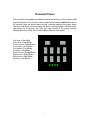
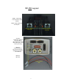
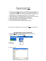
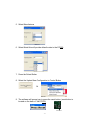
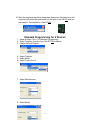
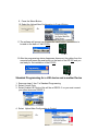
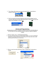
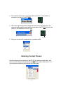
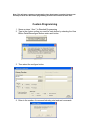
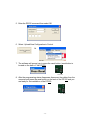
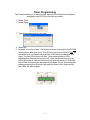
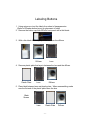
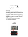
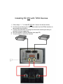
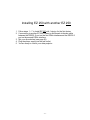
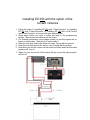
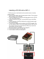
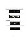
EZ250
L
Owners Manual
i
Table of Contents
EZ 250 Parts List
1
Items Provided by Installer
2
Preloaded Eiki Code
3
Preloaded Timer
4
EZ 250 Layout
5
EZ 250 Software Installations
6
Programming EZ 250
7-17
Labeling Buttons
18-19
Installing EZ 250
20-24
DIP Switch Settings
25
EZ 250 Software Troubleshooting
26
EZ 250 Operational Troubleshooting
26
ii
iii
EZ 250 Parts List
• EZ 250
• AC/DC Power Supply
• EZlink Hub
• Plug and Play Set Up Guide
• 2 Screws
• 2 Label Transparency Sheets
-1-
Items Provided by Installer
• If you are going to need to program the EZ-250, a DB 9 serial cable to connect
your computer to EZ 250
• Slotted screw driver
• Hex driver
• 2 pieces of standard Cat 5 cables to run between the EZ 250 and EZlink Hub
• The control cable that was included with the projector or that was purchased
later
• DB 9 serial cable if connecting to an NPC-1
-2-
Preloaded Eiki Code
PLUG AND PLAY SET UP
Your EZ-250 system is set to operate right out of the box. It has been pre-configured to work with
the current line of EIKI projectors. If you are using one of the projectors listed below simply
connect the control cable from the projector to the RS-232c port on the EZ-250 interface. Connect
two cat5 cables between the same numbered ports (1 to 1, 2 to 2) on the controller and interface.
If you are using a mini-din 8 to DB9 sub cable you must set the dip switches for null modem
operation. After you have connected the EZ-250 controller to the EZ-250 interface and the
projector, connect the power to the EZ-250 interface.
PRESET CODE The configuration for the following data projectors are preset at the factory:
If you are controlling:
LC-X60, LC-X70, LC-XB15, LC-XB21, LC-XB22, LC-XB26, LC-XB30, LC-SB21
NOTHING FURTHER IS REQUIRED!
The default button configuration is:
Button 1 On
Button 2 OFF
Button 3 Volume Up
Button 4 CompositeVid Button 5 Computer 1 Button 6 Black Screen
Button 7 Volume Down Button 8 S-Video
Button 9 Computer 2 Button 10 Auto Image
The other EIKI standard configurations can still be accessed without disconnecting the system. While the controller is
powered up, press button 8 down for 30 seconds (it really takes 30 seconds, please be patient.)After the button
starts to blink, continue pressing the button down. The button will blink once then pause for about
3 seconds then it will blink twice, then pause for 3 seconds, etc. After you have arrived at the
proper number, release Button 8. Each set of blinks loads a different set of drivers for EIKI model
projectors.
One Blink
LC-X60, LC-X70, LC-XB15, LC-XB21, LC-XB22, LC-XB26, LC-XB30, LC-SB21
Two Blinks
LC-XG110, LC-XG210
Three Blinks LC-SD10, LC-SD20
Four Blinks
LC-X6, LC-SX6, LC-XT3, LC-UXT3
Five Blinks
EIP-200, EIP-1500T, EIP-2500, EIP-3500, EIP-4500
-3-
Preloaded Timers
The controller is preloaded with different timers that will turn off the projector after
a specified period. This function can be selected by pressing button 9 down for
30 seconds, after the button starts to blink, continue pressing the button down.
The button will blink once then pause for about 3 seconds then it will blink twice,
then pause for 3 seconds, etc. After you have arrived at the proper number,
release the button. Each set of blinks loads a different timer option:
One hour = One Blink
Two hours = Two Blinks
Three hours = Three Blinks
Four hours = Four Blinks
Five hours = Five Blinks
Six hours = Six Blinks
Seven hours = Seven Blinks
Eight hours = Eight Blinks
Nine hours = Nine Blinks
No timer = Ten Blinks
-4-
EZ 250 Layout
EZllink 1 cable carries
Power and both contact
closures
EZlink 2 cable carries both
RS 232 ports
Connects to EZlink 1
on the hub
Connects to EZlink 2
on the hub
RS-232-1
Hooked up to projector
when using NPC-1
also hooked up to another
device when NPC-1 is not
used or just nothing
RS-232-2
Programming Port
Also goes into the NPC 1
and when two projectors
are hooked up
RS-232-3
Not Used
Contact Closures
wires
-5-
EZ 250 software Installation
1.
2.
3.
4.
Goto http://www.eiki.com
Then select EZ 250 Software
Save to your PC
Then install the program from your desktop
-6-
Programming EZ 250
(Best viewed in 1024 x 768 or higher)
1. To connect your EZ 250 controller to your EZlink Hub interface take two
(2) standard cat5 cables and connect the first cable between EZlink 1 port
on the interface and EZ 1 port on the controller and the second cable to
the EZlink 2 port of the interface and EZ 2 port of the controller.
2. Take a DB9 female to a DB9 female cable and plug one end into RS-2322 port on the interface and the other into your computer
3. Set the dip switches on the EZlink interface (see page 25)
4. Connect the power supply to the EZlink hub .
5. Then choose which level of programming you will need
In this section the different ways to program the EZ 250 will be explained.
Programming using a Saved file
1. Select EZ 250 under EIKI by clicking on the start menu, then all
programs, then EIKI and select EZ 250
2. Select File
3. Then Open
4. Select saved file
-7-
5. Select open Note: a pre-existing file may be modified for current user specs once it is opened.
6. Select the Upload New Configuration to Control Button
Or
7. The software will prompt you to press the reset button. (reset button is
located on the back of the EZ 250)
Reset Button
8. After the programming status disappears disconnect the cables from the
computer and press the reset button on the back of the EZ 250 and you
are ready for the installation of the EZ 250
Reset Button
Standard Programming
1. Select EZ 250 under EIKI by clicking on the start menu, then all
programs, then EIKI and select EZ 250
2. Select Projector (from the top of the EZ 250 software)
3. Select Model
4. Select Control Port 1
-8-
5. Select Manufacturer
6. Select Model this will provide default codes to the EZ 250
7. Press the Select Button
8. Select the Upload New Configuration to Control Button
Or
9. The software will prompt you to press the reset button. (reset button is
located on the back of the EZ 250)
Reset Button
-9-
10. After the programming status disappears disconnect the cables from the
computer and press the reset button on the back of the EZ 250 and you
are ready for the installation of the EZ 250
Reset Button
Standard Programming for 2 Devices
1. Same as steps 1 thru 7 in Standard Programming
2. Select Projector (from the top of the EZ 250 software)
3. Enable Second Projector
4. Select Projector
5. Select Model
6. Select Control Port 2
7. Select Manufacturer
8. Select Model
- 10 -
9. Press the Select Button
10. Select the Upload New Configuration to Control Button
Or
11. The software will prompt you to press the reset button. (reset button is
located on the back of the EZ 250)
Reset Button
12. After the programming status disappears disconnect the cables from the
computer and press the reset button on the back of the EZ 250 and you
are ready for the installation of the EZ 250
Reset Button
Standard Programming for a LSE device and a another Device
1. Same as steps 1 thru 7 in Standard Programming
2. Select Control Ports
3. Select Enable LSE Device (this will be on RS232- 2 so you must connect
your other device on RS232-1)
4. Select Upload New Configuration to Control
Or
- 11 -
5. The software will prompt you to press the reset button. (reset button is
located on the back of the EZ 250)
Reset Button
6. After the programming status disappears disconnect the cables from the
computer and press the reset button on the back of the EZ 250 and you are
ready for the installation of the EZ 250
Reset Button
Advanced Programming
(Changing button functions is not difficult. That said, please bear in mind that calling us
for service after you have modified the code could make you subject to additional
charges)
1. Same as steps 1 thru 7 in Standard Programming
2. You now can select what you would like each button to do thru the EZloader
Data base by going to the button and clicking on the drop down arrow and
selecting the new feature for that button.
3. After you are done with each button Select Upload New Configuration to
Control
Or
- 12 -
4. The software will prompt you to press the reset button. (reset button is
located on the back of the EZ 250)
Reset Button
5. After the programming status disappears disconnect the cables from the
computer and press the reset button on the back of the EZ 250 and you are
ready for the installation of the EZ 250
Reset Button
6. Now you can save the configuration for another install
Selecting Contact Closure
Use the contact closure feature on the EZ 250 by selecting switch relay, and
then pick which button will activate the relay and then select which relay 1 or 2
(you may have multiple buttons select the same relay).
- 13 -
Note: This will setup contacts to momentarily close when button is pushed. Contacts can
be setup to latch. See the custom programming section of this manual to learn more.
Custom Programming
1. Same as steps 1 thru 7 in Standard Programming
2. Type in the custom coding you need for each button by selecting the View
Button Detail/Reconfigure button under each button
3. Then select the configure button
4. Enter in the number of command including start and end commands
- 14 -
5. Enter the RS232 command then select OK
6. Select Upload New Configuration to Control
Or
7. The software will prompt you to press the reset button. (reset button is
located on the back of the EZ 250)
Reset Button
8. After the programming status disappears disconnect the cables from the
computer and press the reset button on the back of the EZ 250 and you
are ready for the installation of the EZ 250
Reset Button
- 15 -
Timer Programming
This Feature allows you to select a timer that will shut off the devices that are
contacted to the EZ 250 for the time you select.
1. Select Timer
2. Select Setup
3. Type in how many hour(s) you need
4. Select OK
5. Example: a four hour timer - the devices that are connected to the EZ 250
will shut down after four hours. The LEDs on the bottom of the EZ 250 are
indicators to let you know how much time is left before the devices shut
down. The first LED will shut off after 1 hour leaving three lit LEDs
indicating that there are three hours left. After the second hour only two
LEDs will remain lit. After the third hour only one will remain lit. This state
leaves one hour before the devices will shut down. At any time during this
process pressing the ON button will reset the timer to four hours and all
four LEDs will light up again.
- 16 -
Labeling Buttons
1. Using scissors cut out the labels from sheet of transparencies
(Refer to EZloader button layout for placement of label)
2. Remove the button cap from EZtrol’s front panel with a thin blade
3. With a thin blade lift the top up of the lens from the diffuser
Diffuser
Lens
4. Remove plastic plate that lays in between the lens and the diffuser
Plastic Plate
Lens
Diffuser
5. Place label between lens and plastic plate. When reassembling make
sure the flat end of the plastic plate faces the lens
Black
Screen
Lens
Plastic Plate
- 17 -
Diffuser
6. Place Diffuser back into lens and then back onto Controller, repeat until all
10 buttons are identified.
7. If the Label you need is not on the printed sheet then open up EZ 250
software
8. After EZ 250 software is open select labels
9. Select layout
10. Select the button you would like to change and click on it then type in the
new label
11. After your done customizing the labels, select print
(Use transparencies for best results)
Note: blank transparencies not provided they can be obtained at a local office supply
store
- 18 -
Installation of EZ 250
Installing EZ 250 with ONE Device
1. Pull the two pieces of Cat 5 cable from the controller location to the data
projector location
2. Place the EZlink interface near the data projector location. This is
recommended because you will already have a 110v power outlet there.
3. Connect the control cable that is coming from the data projector into the
port that it was programmed for, either RS-232-1 or RS-232-2 on the
EZlink interface
4. Connect the power to the EZlink interface (do not plug the power into the
wall outlet yet)
5. Connect the cat5 cables from the interface to the EZ 250 controller. Plug
one cat5 cable into the EZlink 1 port on the interface and then to EZ1 on
the controller. Plug the second cat5 cable into EZlink 2 on the interface
and EZ2 on the controller
6. Set the dip switches on the EZlink interface (see page 25)
7. Plug the power supply into the wall outlet
8. You are ready to control your data projector
- 19 -
Installing EZ 250 with TWO Devices
1. Follow steps 1 – 7 in Install EZ 250 with 1 device for the first device
2. For the second device pull a DB9 serial cable from the EZlink interface to
the second device location
3. Connect the cable that is coming from the device into the port that you
selected during programming.
4. Set dip switches on EZlink interface (see page 25)
5. You are ready to control two devices
- 20 -
Installing EZ 250 with another EZ 250
1. Follow steps 1 – 7 in Install EZ 250 with 1 device for the first device
2. If connecting to another EZ 250 connect a db9 female to female cable
between the RS232- 2 port on the first EZlink interface and the RS232-2
port on the second EZlink interface.
3. Set your dip switches (see page 25)
4. Plug the power supply into the wall outlet
5. You are ready to control your data projector
- 21 -
Two EZ 250s
- 22 -
Installing EZ 250 with the option of the
contact closures
1. Follow the steps in “Installing EZ 250 with 1 Data Projector” or “Installing
EZ 250 with 2 Data Projectors” or “Installing EZ 250 with a LSE Device
and a Data Projector” to connect with your data projector.
2. Setup which button you want to select the relay in the programming
section. Then connect your device into the relays.
3. For Example connecting a low voltage screen you would program the on
button to switch relay 1 and the off to switch relay 2.
4. Place the wire that controls the down into relay 1 along with the ground
5. Place the wire that controls the up into relay 2 along with the ground
6. Now when you turn the control on the screen will come down and the data
projector will turn on
7. When you turn the control off the screen will go up and the data projector
will turn off
- 23 -
Installing a EZ 250 with a NPC-1
1. Pull the two pieces of cat5 cable from the controller location to the data
projector location
2. Place the EZlink interface near the data projector location. This is because
there is already a 100v outlet there.
3. Connect the cable that is coming from the data projector into the RS-2321 port of the EZlink interface
4. Connect the cable from the NPC-1 into the RS-232-2 port of the EZlink
interface
5. Connect the power to the EZlink interface (do not plug the power supply
into the wall outlet yet)
6. Connect the cat5 cables from the interface to the EZ 250 controller. Plug
one cat5 cable into EZlink 1 port on the interface and then to EZ1 port on
the controller. Plug the second cat5 cable into EZlink 2 port on the hub
and the EZ2 port on the controller
7. Set the dip switches on the EZlink Hub (see page 25)
8. Connect the power supply to the wall outlet
9. You are ready to control your data projector
- 24 -
When connecting to program the EZtrol 250 with a standard DB9 Cable into RS-232-2
When connecting to devices on either RS-232-1 or RS-232-2 with a standard DB9 Cable
When connecting to devices on either RS-232-1 or RS-232-2 with a null modem DB9 Cable
When connecting to RS-232-1 with a standard DB9 cable and connecting to RS-232-2 with a
null modem DB9 cable
When connecting to RS-232-1 with a null modem DB9 cable and connecting to RS-232-2 with
a standard DB9 cable
- 25 -
EZ 250 Software Troubleshooting
1.
2.
3.
4.
Make sure that the connections are seated tightly
Check dip switch settings
Are you connected to RS 232 Port (2)?
If you do something in changing the buttons that you didn’t want to do,
select the restore factory setup button. This will set everything back to
original factory specs.
EZ 250 Operational Troubleshooting
1. If the data projector does not require a null modem connection you
make the connections the same as you did at the EZtrol. If it does
require a null modem connection change the RX and the TX at the
EZlink interface by resetting the dip switches.
2. Make sure if connecting between EZ 250 devices you are using
RS 232 Port (2)
- 26 -


![[U4.81.11] Opérateur INTE_MAIL_2D](http://vs1.manualzilla.com/store/data/006383603_1-5bedf7acd72563c373a0316d0a0fdc14-150x150.png)
![[U4.81.11] Opérateur INTE_MAIL_2D](http://vs1.manualzilla.com/store/data/006352805_1-b926fff30e68d0838032527c8f7d4f51-150x150.png)