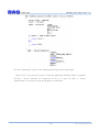
1
USB-EK01 Users Manual (Rev 1.0)
USB-EK01
User Manual
AN2131, EZ-USB and Cypress are trademarks of Cypress Semiconductor, Keil and uVision2 are trademarks of
Keil software. Windows, Windows2000, Windows NT and Windows XP are trademarks of Microsoft. We
acknowledge that the trademarks or service names of all other organizations mentioned in this document as their
own property.
The information in this document is subject to change without notice and no part of this document may be copied
or reproduced without the prior written consent.
Copyrights 2005 DAQ system, All rights reserved.
-1-
http://www.daqsystem.com
USB-EK01 Users Manual (Rev 1.0)
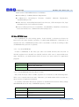
Contents
1. Introduction
2. USB-EK01 Function & Specification
3. Installation
3.1 Confirm Product Contents
3.2 Cypress Development kit Installation
3.3 Board Driver Installation
4. USB-EK01 Description
4.1 USB-EK01 Concept
4.2 Memory Map
4.2.1 EK01 Memory map
4.2.2 IK01 Memory Map
4.3 Booting Option
4.4 CDROM Folder
5. Test
5.1
5.2
5.3
5.4
5.5
5.6
Example
Program & Debugging with KeiluVision
USB Firmware
Make USB PC Driver
Make EEPROM Image
Application Program for PC
Appendix
A Driver Installation & Remove
B Board connector PIN map
C Notice
Reference
-2-
http://www.daqsystem.com
USB-EK01 Users Manual (Rev 1.0)
1. Introduction
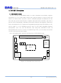
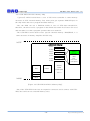
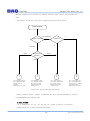
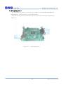
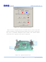
JP1(Boare Extention)
JP2
DAQ system
JP3
www.daqsystem.com
P1
RS232
connection
D1 D2 D3
SW1
SW2
AN2131
Reset
SW3
JP4
Power
JP5
(USB B type
Connector)
JP6
D4
JP7(Boare Extention)
[Figure 1-1. USB-EK01 Out-side View]
Above picture views board out-side, it display Reset switch and Power LED which
light on when power supply with connection cable. More specific information refer to
“4.1 USB-EK01 Concept”.
-3-
http://www.daqsystem.com
USB-EK01 Users Manual (Rev 1.0)
2. USB-EK01 Function & Specification
<Function>
- USB Protocol Test & Development
- 8051 Program Test & Development
- PC용 USB device driver Test & Development
- Step by Step Debugging Practice
<Specification>
- Full speed (12Mbps) USB Support
- Advanced using 8051 core Micro-Controller
- Convenient Interface USB SIE (Serial Interface Engine)
- Step by Step Debugging & 8051 Compile Test (Code size limited 4K)
- Power Supply through USB Cable (Max. 500mA)
- Two RS232 interface (Maximum transfer speed-115200bps) Debugging or
It can use special purpose.
- Board Reset & Firmware Program Load through USB
- Easy device development through Cypress의 Development Kit
- Usable evaluation Keil Compiler & Debugger (Limit 4K code)
-4-
http://www.daqsystem.com
USB-EK01 Users Manual (Rev 1.0)
3. Installation
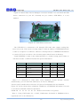
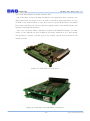
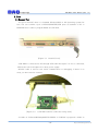
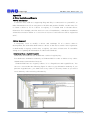
3.1 Confirm Product Contents
[Figure 3-1. USB-EK01 Main Contents]
(1) USB-EK01 Evaluation board
(2) USB (A-B) Cable
(3) 9Pin Null Modem cable
(4) CD (Manual/Schematic/Sample test etc..)
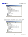
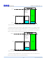
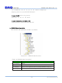
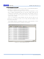
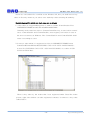
3.2. Cypress Development kit Installation
A development and exercise of board refer to mainly Development Kit at Cypress,
you can get a lot of information and report. You can use the ”Development kit” to
download at homepage of Cypress. (“www.cypress.com”) The “Development kit “ is a
software package minimum 60Mbyte size, If it install, the folder structure is as follows.
-5-
http://www.daqsystem.com
USB-EK01 Users Manual (Rev 1.0)
[Figure 3-2. Folder Structure]
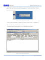
[Notice] If you want a Keil software and separate reference report, you shall select a
custom install option not default.
You confirm a folder at your PC as above picture when normally finished install.
The Cypress Development Kit include Keil compiler and debugger, you can freely use
a code size of 4K byte in range not business purpose.
-6-
http://www.daqsystem.com
USB-EK01 Users Manual (Rev 1.0)
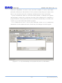
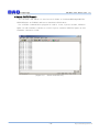
3.3 Board Driver Installation
(Notice) All test made a Windows2000 Professional with bases, we are having finished
the final test at Windows XP.
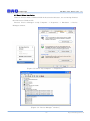
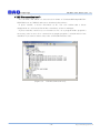
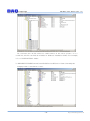
Execute “Device Manager” at My Computer -> Properties -> Hardware -> Device
Manager window.
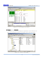
[Figure 3.3 Select “My computer”->”Properties”]
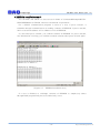
[Figure 3.4 “Device Manager” window]
-7-
http://www.daqsystem.com
USB-EK01 Users Manual (Rev 1.0)
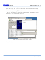
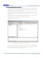
Figure 3.4 shows that “Device Manager” execution window. You can check all USB
device connection at your PC. Currently not yet connect “USB-EK01”, it is not
marked.
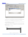
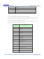
[Figure 3.5 USB-EK01 Connection]
The USB-EK01 is connected to PC through USB cable after jumper setting like
above red circle. The reason of using jumper is that an address of EEPROM(24LC64)
is able to recognize it at AN2131. AN2131 is having function of EEPROM information
to connect I2C port can select a lot of booting option when Power On Booting.
Usable EEPROM is same as the following table to a board booting option. Refer to
“I2C Boot Loader” of AN2131 manual for special information.
Bytes
EEPROM
A2
A1
A0
16
24LC00
N/A
N/A
N/A
128
24LC01
0
0
0
256
24LC02
0
0
0
4K
24LC32
0
0
1
8K
24LC64
0
0
1
When it is connected to USB cable, “New Hardware Search Wizard” execute
automatically, you can check the USB device at “Device Manager”.
It don’t require another driver because of Cypress Development Kit was installed.
Figure 3.6 will be shown after completely installation. An EEPROM information of board
is as follows at default (when first purchase).
0000h: B0
47
05
80
00
00
00
(Refer to file 2100.iic at Cypress)
That is, Using VID(Vender ID) = 0x547, PID(Product ID)=0x80 in EEPROM will be
registered to PC in an USB device.
-8-
http://www.daqsystem.com
USB-EK01 Users Manual (Rev 1.0)
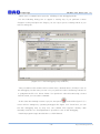
[Figure 3.6 A board was registered with default to PC]
If the jumper don’t connect, the screen is as follows. The way that you can confirm,
after remove jumper, reset switch of a board is “ON/OFF” or reconnect a USB cable
after remove. For more specific information, refer to “Chapter 4.3 Booting Option”.
[Figure 3.7 A board was registered to PC without recognition EEPROM]
-9-
http://www.daqsystem.com
USB-EK01 Users Manual (Rev 1.0)
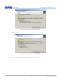
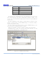
You confirm to register to PC like figure 3.6 that rebooting a board after connection
jumper. After that, “EZ-USB Control Panel(EzMr.exe)” utility which given Cypress
Development Kit perform.
[Figure 3.8 EZ-USB Control Panel]
(Notice) When development a product at Cypress, Usable utility is searchable in
“Cypress\USB \Bin” and “Cypress\USB\Util”.
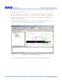
The execution screen of “EZ-USB Control Panel(EzMr.exe)” is like figure 3.9.
If connection doesn’t work a device, the error message will be marked.
[Figure 3.9 EZ-USB Control Panel]
- 10 -
http://www.daqsystem.com
USB-EK01 Users Manual (Rev 1.0)
For more usage method of Control Panel, refer to “EZ-USB Contents and tutorial.pdf”
at Cypress.
From now, the board installs to a “DAQ system” development board so that
registration works to PC. Basically all test above setting even is possible, a driver of
DAQ system shall be install in case of the debugging that used Keil software in order to
put a necessary image to a board. The Vender ID which used to installation is “FFFF”,
this is not the ID which it was registered and I used it as I select temporary.
When Power On Reset, it will act to any contents and a report judges the contents as
reading the first byte of EEPROM connected to I2C.
If the first byte is not ‘0xB0’ or ‘0xB2’, it is performed with default as judge it to
things without EEPROM. (Vender ID 0x0547, Product ID 2131).
It shall modify contents of EEPROM so that recognition gets a board done to a
development board of DAQ system. (Vender ID 0xFFFF, Product ID 0001)
For more detailed egarding boot option, refer to “Chapter 4.3 Booting Option”.
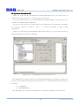
A way to modify of EEPROM is as follows.
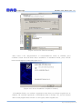
When press “EEPROM” button at EZ-USB Control Panel, “file dialogue box” appears.
When it is selected a file “Sample.eep” of Program\EPROM_IMG folder in CDROM and
press open button, will be changed a contents of EEPROM.
[Figure 3.10 “sample.eep” for changing EEPROM’s information]
- 11 -
http://www.daqsystem.com
USB-EK01 Users Manual (Rev 1.0)
The contents that it was changed are as follows.
0000h: B0
FF
FF
01
00
00 00, in other words, VID is 0xFFFF and PID is 0x0001.
When finished EEPROM writing, press reset switch or remove and re-connect the USB
cable. The board gets re-registration at PC.
And then, above ID doesn’t currently get registration at PC, “New Hardware Search
wizard” will be open and display like figure 3.11.
[Figure 3.11 New Hardware search Wizard Window]
Press “Next” button.
- 12 -
http://www.daqsystem.com
USB-EK01 Users Manual (Rev 1.0)
[figure 3.12 Driver Installation Window]
Press “Next” button.
[Figure 3.13 Driver File Search Window]
After select a location like above figure, press “Next” button.
- 13 -
http://www.daqsystem.com
USB-EK01 Users Manual (Rev 1.0)
[Figure 3.14 Driver Selection window]
After select a file “daqusbw2k.inf” in Software\Driver folder at CDROM, press
“Confirm” button and will finish driver installation. If installation finish, press “finish”
button and disappear window like figure 3.15.
[Figure 3.15 Driver Installation Completion window]
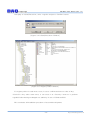
If installation finish, you confirm a registration state that you perform “regedit.exe” at
Window. All contents registered to OS(Windows) that is saving to PC, stored contents
and revised program that can edit it is an registry editor(regedit.exe).
- 14 -
http://www.daqsystem.com
USB-EK01 Users Manual (Rev 1.0)
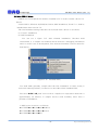
At display of “Start/Execution”, write “regedit” and press “Confirm” button.
[Figure 3.16 “Start/Execution” Window]
[Figure 3.17 Registry Editor Window]
If a registry editor is used most a case, it use to confirm and erase a value of key.
(Notice)If a key value want erase, it can erase it at “Security” items as it perform
regedit32 after having exchanged use authority in case of Windows2000.
This concludes all installation procedure of test and development.
- 15 -
http://www.daqsystem.com
USB-EK01 Users Manual (Rev 1.0)
4. USB-EK01 Description
4.1 USB-EK001 Concept
A basic concept of USB-EK001 made it so that a hardware and software engineer
developed it so as to easily make various tests, and an engineer of various levels can
utilize it. In other words, a person to touch a embedded program and hardware for the
first time, the person whom he/she is familiar with other microcontroller, and want to
practice 8051 programming, embedded USB board Firmware development, USB device
driver development for PC, Application Programming through using USB interface at PC,
and we made it to use debugging practice step by step when embedded firmware
development. User can test all functions only using the USB-EK01 board, all
development tools can use it to free or evaluation type. Also, you can easily use because
you don’t need special power supply.
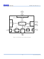
Now I will explain main connection and functions of USB-EK01 board.
JP1(Boare Extention)
JP2
USB-EK01 Board
JP3
P1
RS232
connection
D1 D2 D3
SW1
SW2
AN2131
SW3
JP4
JP5
(USB B type
Connector)
JP6
D4
JP7(Boare Extention)
[Figure 4.1 USB-EK01 Out-side View]
- 16 -
http://www.daqsystem.com
USB-EK01 Users Manual (Rev 1.0)
[Table 4.1
USB-EK01 Function Description]
No.
Name
Description
1
SW1
General Purpose Input
2
SW2
General Purpose Input
3
SW3
Reset
4
D1
General Purpose Output
5
D2
General Purpose Output
6
D3
Program Break Output
7
D4
Power Lamp
8
JP1
Address/Data/ I/O extension connector
9
JP2
Extension RS232 Interface(COM2)
10
JP3
Extension I2C Interface
11
JP4
Extension power connector. It can use to connect
external power supply in case of power need a more
than 500mA.
12
JP5
USB B type connector (Host connection)
13
JP6
Power selection connector(It select a power whether
get from the power at USB cable or external electric
power supply banner.)
14
JP7
Address/Data/ I/O extension connector
15
P1
RS232C connection, it can use a debugging and
general communication to maximum 115200bps.
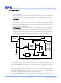
Figure 4.2 shows USB-EK01 functional block diagram, we put emphasis to
expansibility and a design was performed around the main AN2131QC chip. All Data,
Address, I/O can exchange a board expansion, can connect external device through
RS232C, USB, I2C interface.
We made it so as there was a LED and Tact switch, and to be able to test the simple
external input/output test automatically, and don’t need an external power supply
because basically power supply get from USB cable.
- 17 -
http://www.daqsystem.com
Addr, Data, I/O
USB-EK01 Users Manual (Rev 1.0)
Board Expantion
Addr, Data, I/O
USB-EK001
COM1
Switchs
and
LEDs
AN2131
I/O
T/RxD
RS232
COM1
JP4
+5V
P/S
SCL/SDA
EEPROM
+5V
JP3
I2C
USB
USB
+5V
D+/-
+3.3V
[Figure 4.2 USB-EK01 Functional Block Diagram]
- 18 -
http://www.daqsystem.com
USB-EK01 Users Manual (Rev 1.0)
4.2 Memory Map
4.2.1 USB-EK01(8051) Memory Map
Figure 4.3 shows general 8051 Microcontroller memory structure.
The 8051 is equipped with a memory which display inside dotted line, it is
different from memory which it use external data/address bus.
0xFFFF
XDATA
CODE
8051 Internal
SFR
IDATA
DATA
BDATA
0x0000
REGs
[Figure 4.3 8051 Memory Map]
An area to be possible to direct addressing methods in the inside is from 0x00 to
0x7F, address from 0x00 to 0x1F is used to the register bank(0 ~ 3) which it is used
when it operate at CPU. BDATA is from 0x20 to 0x2F, is able to the addressing in a
bit unit. From 0x80 to 0xFF of address is SFR(Special Function Register) area when
access to direct addressing methods, is general data area(IDATA) when access to
indirect addressing methods. The SFR area has the registers for CPU calculation and
for control surrounding I/O area.
8051 has separate space of the data memory area(XDATA) and the program
memory area(CODE), each area accessing classify to signal line of “RD/WR” and
“PSEN”. The program memory (CODE) can include in chip oneself, each
manufacturing company is able to choose various selection until the maximum 64K
Byte at 4K Byte. A mainly flash memory uses in now, user prefer that it is able to
exchange a structure of program. At this time, an input state of “EA” pin decides
whether or not there is to use an external memory whether or not there is to use
inner memory.
- 19 -
http://www.daqsystem.com
USB-EK01 Users Manual (Rev 1.0)
4.2.2 USB-EK01(AN2131) Memory Map
Cypress의 AN2131 which have a core of 8051 microcontroller is same memory
structure of 8051 internal memory. But, other point got separate RAM(8K Byte) in
the chip inside and use to program and data memory.
Also, the RAM can use a EndPoint buffer in case of USB data transmission,
therefore, the driver write a program in this RAM area when first Power ON reset
and can make it so that a program operates that user wanted it.
The USB-EK01 board doesn’t have special external memory (RAM/ROM), it is
same structure of memory map like AN2131 chip.
0xFFFF
AN2131QC Internal
0x7FFF
0x7B40
0x27FF
0x2000
0x1FFF
0x1B40
REGs/Buffers
DATA
REGs/Buffers
0x1B3F
SFR
IDATA
DATA
USB control
registers
192 Bytes
16x64
Bulk
End points
(1024 Bytes)
XDATA/
CODE
6,976 Bytes
EA = 0
BDATA
0x0000
REGs
[Figure 4.4 USB-EK01(AN2131) Memory Map]
But, if the USB-EK01 board use an expansion connector and it connect with USBIK01, the board can use external memory area.
- 20 -
http://www.daqsystem.com
USB-EK01 Users Manual (Rev 1.0)
4.2.3 USB-IK01(Expansion Board) Memory Map
The USB-IK01 board used RAM and ROM to the application that a memory size
and program size was large so as to be able to extend an external memory. In case
of ROM, it use Flash memory so user don’t need to special ROM Writer, and added
LED switch (DIP/Tact) for I/O test, and was equipped with a chip (PCF8574) that can
expand I/O through I2C interface.
Also, user can freely make a hardware program with EPLD(XC9536XL). (In other
words, it can exchange an area of address and usage methods of I/O.) This modify
can perform to connect a printer port of PC without special device.(Inclusion ISP
interface itself).
[Figure 4.5 USB-IK01 Out-side View]
[Figure 4.5 USB-IK01 and USB-EK01 combination]
- 21 -
http://www.daqsystem.com
USB-EK01 Users Manual (Rev 1.0)
USB-IK01 Board
0xFFFF
(Note) Can be
programed the
location by
EPLD
programming
and DIP sw.
0x7FFF
RAM32K
CODE or
XDATA
AN2131QC Internal
FLASH 64K
CODE
0x2000
0x1B40
0x0000
[Figure 4.6 When USB-IK01 and USB-EK01 combination Memory Map(EA = 0)]
If EA pin of chip is Low Level(‘0’), the program memory use a RAM of inside
AN2131 chip. But, if EA pin of chip is High Level(‘1’), it use external memory area.
In other words, it decide on whether or not there is to perform the first program to
enforce in where with EA pin input state when 8051 reset.
USB-IK01 Board
0xFFFF
(Note) Can be
programed the
location by
EPLD
programming
and DIP sw.
0x7FFF
RAM32K
CODE or
XDATA
AN2131QC Internal
FLASH 64K
CODE
0x2000
0x0000
[Figure 4.7 When USB-IK01 and USB-EK01 combination Memory Map(EA = 1)]
If EA pin of chip is High Level(‘1’), the external memory area is not affected, the
RAM of inside AN2131 chip can use general memory.
- 22 -
http://www.daqsystem.com
USB-EK01 Users Manual (Rev 1.0)
4.3 Booting Option
In case of AN2131, there is three reset mode.
(1) Power On Reset : When power on, let reset state stay to EZ-USB core as much
as a time constant at external RC circuit until internal PLL becomes stabilization.
At this time, a value of register inner chip become initialization to fixed prices.
(2) 8051 Reset : It exchange a value of “CPUCS” register at EZ_USB core, and can
control a reset of 8051 core. When Power On Reset, a value of initialization is a
reset state. In order to get out of this state, when modify through USB at
Host(PC), when EEPROM load or external program memory using(EA=1), the
reset is released automatically.
(3) USB Bus Reset : If SE0 state(D+ and D- is all low) is kept more than 10mSEC
at Host(PC), it perceive at EZ-USB core automatically, it inform this to 8051 to
generate interruptINT2). Most registers aren’t affected when USB Bus Reset.
Mainly registers related to USB data transmission are set up to initial prices.
EA
EEPROM
I2C
USB
USB Bus Reset
+3.3V
Reset
12Mhz
XIN/OUT
Power ON
Reset
EZ-USB
Core
8051 Reset
Address
Reset
8051
Core
Oscillator
PLL
/2
48Mhz
Data
CLK24
24Mhz
[Figure 4.8 AN2131 Reset and Booting]
If the AN2131 is released to Power On Reset, first “I2C Boot Loader” operates, it
confirm that EEPROM is connected to an external I2C bus. If EEPROM operates
(Ack is asserted), it decide according to data of EEPROM first byte how to operate.
If there isn’t EEPROM, it releases 8051 at reset so as to be able to bring a program
at external program memory as inspect a state of EA pin if it is ‘1’. VID/PID/DID
get a value at external programs and register it to Host(PC).
If there is EEPROM, if the first byte value isn’t 0xB0 and B2, the VID, PID of
- 23 -
http://www.daqsystem.com
USB-EK01 Users Manual (Rev 1.0)
AN2131 registers it to Host(PC) to 0x0547, 0x2131. 8051 core is stayed with reset
state.
The Figure 4.9 shows by an action regarding booting to Flow Chart.
Power On Reset
'1'
Not Detected
Check EA
Check EEPROM
'0'
Detected
0xB2
Others
Check Byte at
Address 0
0xB0
VID = EEPROM 1/2 Bytes
PID = EEPROM 3/4 Bytes
Program code from
EEPROM
Release 8051 from Reset
4
3
2
1
VID = EEPROM 1/2 Bytes
PID = EEPROM 3/4 Bytes
8051 remains in Reset
Program code may be
loaded from host
VID = 0x0547 (Cypress)
PID = 0x2131(EZ-USB chip)
8051 remains in Reset
Program code may be
loaded from host
VID = from Program code
PID = from Program code
Program code from external
CODE memory area
Release 8051 from Reset
[Figure 4.9 AN2131 Booting Sequence]
Below contents shows a sample of EEPROM. For more special information, refer to
“5.4 EEPROM Image making” part.
In case of 0xB0
(ex. 1) 0000h: B0
47
05
80
00
00
00
(Refer to 2100.iic of Cypress)
ezmon.sys driver is used. VID 0547 PID 0080
- 24 -
http://www.daqsystem.com
USB-EK01 Users Manual (Rev 1.0)
(ex. 2) 0000h: B0
FF
FF
01
00
00
00
(Refer to sample.eep)
daqusb.sys driver is used. VID FFFF PID 0001
In case of 0xB2 (refer to fw_out.eep)
0000h: B2
FF
FF
01
00
00 00
In case of others(it is not 0xB0 or B2)
ezusb.sys driver is used. VID 0547 PID 2131
4.4 CDROM Folder description
The structure and explanation of folder is as follows.
[Figure 4.10
CDROM Folder Structure]
[Table 4.2 CDROM Folder Description]
Folder Name
Description
Document
Manual
Hardware
Schematic and BOM
Software
Source Code (Application/Driver/Sample/EEPROM image)etc..
Utility
RS232C communication Program for test (comm.exe)
- 25 -
http://www.daqsystem.com
USB-EK01 Users Manual (Rev 1.0)
5. Test
5.1 Example Test
You get a Host(PC) that it is installed Windows2000 or XP Operating system for
test. You can confirm a port of RS232/PRINTER/USB ports at backside of PC. A
PRINTER Port is able to program EPLD of USB-IK01.
[Figure 5.1
Host(PC) Port]
USB-EK01 is connected to PC through USB cable like figure 5.2. If it is connected,
LED in the red circle lights on to show power supply.
RS232C cable is used to test serial communication or debugging. If there is no
used, you don’t need to connect.
[Figure 5.2
USB-EK01 and PC connection using cable]
A folder of “Software\Example\USB-EK0\” in CDROM is prepared a folder to
- 26 -
http://www.daqsystem.com
USB-EK01 Users Manual (Rev 1.0)
each test. Adjustment of source code uses Keil compiler. If every each folder
performs a Keil project file(extension .Uv2) by double clicks, the project opens. Also,
there is an execution binary file of Intel hex format(extension .hex) each folder.
If press “DownLoad” button at “EZ-USB Control Panel”, a dialogue box appears
and designates a binary file to perform at boards. If file transmission is completed, a
program loaded is newly performed at microcontroller automatically as it make reset
of 8051 core at “EZ-USB Control Panel” program.
If it is loaded file at once, it use to press “ReLoad” button as it is remembering
information of a file loaded next time. At this time, file dialogue box don’t appear.
[Figure 5.3
A way downloading an executable file(*.hex) to USB-EK01]
- 27 -
http://www.daqsystem.com
USB-EK01 Users Manual (Rev 1.0)
< LED lighting test >
You can find a file which it is used to test in folder of “Software\Example\USBEK01\Led” at CDROM, and test to download led.hex.
After execution, a LED (D1 and D2) in the red circle repeat alternately lighting and
lights out.
[Figure 5.4
LED lighting test]
- 28 -
http://www.daqsystem.com
USB-EK01 Users Manual (Rev 1.0)
< Serial communication test >
You can find a file which it is used to test in folder of “Software\Example\USBEK01\Serial” at CDROM, and test to download “serial.hex”.
For a RS232 communication program is used to a test, the program that it is used
most is Windows HyperTerminal. But, we used the “comm1” which was the
communication program that it made at DAQ system. The USB-EK01 connects to
PC with RS232 cable and executes program “comm.exe”. This program can find in
“Utility” folder at CDROM.
First, it fit communication setting (Baudrate, Stop bits, Data bits, Parity etc.) at
program. We use COM1 like a picture, we use a setup value that 38400bps, 8 data
bit, 1 Stop bit, Parity None.
The program perform to download at the board, it send repeatedly an ASCII
character like the following picture and display at PC program.
[Figure 5.5
Serial communication test]
- 29 -
http://www.daqsystem.com
USB-EK01 Users Manual (Rev 1.0)
< Switch ON/OFF test >
You can find a file which it is used to test in folder of “Software\Example\USBEK01\Switch” at CDROM, and test to download “Switch.hex”..
For a RS232 communication program is used to a test, if press switch1, LED(D1)
lights on and transmits contents to serial. If press switch2, LED(D2) lights on and
transmits contents to serial.
[Figure 5.6
Switch ON/OFF test]
- 30 -
http://www.daqsystem.com
USB-EK01 Users Manual (Rev 1.0)
< EEPROM read/write test >
You can find a file which it is used to test in folder of “Software\Example\USBEK01\EEPROM” at CDROM, and test to download “eeprom.hex”..
For a RS232 communication program is used to a test, if press switch1, it
transmits through communication as reading contents of EEPROM. If press switch2,
0x11 record from address of 0 to address of 10 of EEPROM.
So, first after press switch1, you confirm contents of EEPROM. To press switch2,
new information is writing, you confirm recorded contents after press switch1 again.
[Figure 5.7
EEPROM read/write test]
If a test is finished, to exchange contents of EEPROM to sample.eep values
through EzMr program and proceed continuously a test.
- 31 -
http://www.daqsystem.com
USB-EK01 Users Manual (Rev 1.0)
< USB Disconnection test >
You can find a file which it is used to test in folder of “Software\Example\USBEK01\Discon” at CDROM, and test to download “discon.hex”.
If press switch1, a device disconnect at PC. You can confirm that a driver
disappeared at a “Universal Serial Bus controllers” of device manager.
If press switch2, a device try to reconnect to PC. As a program didn’t program a
necessary code in case of re-connection at sample program, a suitable driver isn’t
installed. If you want to add a code, refer to EZUSB firmware code.
[Figure 5.8
USB Disconnection test]
- 32 -
http://www.daqsystem.com
USB-EK01 Users Manual (Rev 1.0)
5.2 Program and Debugging with Keil uVision
Used program used a LED lighting sample program for simple explanation. An
evaluation copy of Keil program is together it to Development Kit providing Cypress,
you shall select a option in case of installation.
Usage of a necessary program refers to Keil C51 manual to a test. You can get
detailed information in Keil Web site. You can use the evaluation copy to download
Keil Web site.
First, double click Software\Example\USB-EK01\Led.Uv2. (If Keil software
installation normally worked, a project opens like below picture.)
An extension of project is .Uv2.
[Figure 5.9
Keil program execution window]
You make simply complie as you adjust ON/OFF time. (For more information of
uVision refer to Keil manual.) A led.hex file is generated if compiled, you try to
perform it to download at board with using EzMr.exe.
- 33 -
http://www.daqsystem.com
USB-EK01 Users Manual (Rev 1.0)
[Figure 5.10 a way to download execution binary (*.hex) at USB-EK01]
The above way is a way testing a direct execution code after download through
USB connection, a way of debugging with serial communication is as follows.
As the debugging uses a serial communication(COM1 at board), you cannot use it
with comm.exe program at the same time.
If using com2 at board, after being load with a ”mon-int-sio1.hex” monitor
program to a board, you shall use it as making JP2 of a board and the separate cable
which can connect.
The cable connection is as follows.
5264-03
DSUB 9pin
1
2
3
3
2
5
1
4
6
7
8
9
[Figure 5.11
COM2 Cable connection]
- 34 -
http://www.daqsystem.com
USB-EK01 Users Manual (Rev 1.0)
And it uses a communication speed to 19200bps in the debugging mode.
For the following Dialog box to appear a setting way if you perform a menu
“Target1” at Project/Option for Target, you set it up to press a setting button as you
select a debug tab.
[Figure 5.12
Keil Debugging setup window1]
And you shall use the monitor driver which isn’t a default driver of DAQ in case of
the debugging. At this time you test it as you perform it after confirming contents of
a cpdaqmon.bat file of a Driver folder. You perform it after disconnecting a board
with PC when you use batch command.
In the state that loading became a project and press
button like figure 5.9, a
screen will be changed by operating debugger like figure 5.12. From here you can
test the debugging step by step. You can confirm CPU register, memory data
assembly nicmonic etc. and adjustment is possible in case of the debugging.
Detailed program usage should refer to a Keil Manual.
- 35 -
http://www.daqsystem.com
USB-EK01 Users Manual (Rev 1.0)
[Figure 5.13
Keil Debugging setup window2]
5.3 Firmware(Ezusbfw) Description
A firmware source code is providing that it implemented a basic USB protocol at
8051 cores to developers at Cypress. You can find a source code as like picture.
[Figure 5.13
Firmware source folder]
- 36 -
http://www.daqsystem.com
USB-EK01 Users Manual (Rev 1.0)
If double clicks “fw.Uv2” at the above screen, the project is opened at Keil
program as like below picture.
See the figure 5.14, A file used 5(fw.c periph.c dscr.a51, ezusb.lib, usbjmptb.obj),
VID/PID and string table which it is used USB device registration can find at
DSCR.A51(Assembly Source Code) and it can modify. Most of application code
modify at Periph.c and can use.
USBJmpTb.OBJ is object code. But, it can find in “Target\lib” folder with a source
form and can use. Ezusb.lib can modify and use to fit the developers.
[Figure 5.14
VID/PIC Modify]
For more detailed usage and contents, refer to “Anchor Firmware FW.pdf” file.
- 37 -
http://www.daqsystem.com
USB-EK01 Users Manual (Rev 1.0)
5.4 Make USB PC driver
DDK(Driver Development Kit) shall be installed to PC in order to make a driver for
Win32.
Usable DDK is Windows 98/2000/me. Before DDK installation, Visual C++ shall be
installed more than version 5.0.
The environmental setting order that can be made from a driver is as follows.
(1) Visual C Installation
(2) DDK Installation
You can see a figure 5.15 after finished installation. Checked build
environment is a compile environment which involved a debugging information
and it is used in case of development, Free build environment is used a driver for
distribution.
[Figure 5.15
Installed DDK]
You shall make generally compile after the first installation. In other words, if
each environment performs, it will move to the folder which installed DDK.
Execution build –cZ, total source will be compiled. An expectation lead time is
approximately 30 minutes. If compile doesn’t work normally, there have a
problem of installation.
A DDK source location is as follows.
♣ NTDDK₩src₩wdm₩usb₩bulkusb
♣ NTDDK₩src₩wdm₩usb₩isousb
♣ NTDDK₩src₩wdm₩hid
- 38 -
http://www.daqsystem.com
USB-EK01 Users Manual (Rev 1.0)
(3) Driver Compile
A driver source to provide to a sample at Cypress is ezloader, ezmon, ezusbdrv
three this. It can find a “Drivers” folder, three drivers entire source is same, but
there is some difference.
Ezmon and ezusbdrv differ in having download file or not. Ezmon has keil
debugger binary image, download automatically usable to the debugging when
registration. Ezusbdrv doesn’t have download binary image, it register default
USB only, stay 8051 with reset state. Most of I/O routines related USB are
removed in case of Ezloader, the code can download when booting. You had better
to use a source of ezmon.
You can make a binary image to use first booting, and have to compile it. A way
is as follows that you made it.
First, the program that it is performed make by Keil compiler. A result file is
xxx.hex. The binary image that it was used when it made a daqmon.sys driver
used a Keil debugger monitor “mon-int-sio0.hex”. The reason that I used, I want
use an image to use internal memory and COM1to a debugging port. And, let you
convert hex output by source “c” source code as you use hex2c utility.
“hex2c.exe mon-int-sio0.hex mon-int-sio0.c”
You make compile as you copy the source which let you convert it to
“mon51hi.c”. A screen that it is compiled is as follows.
[Figure 5.16
Device Driver Compile]
- 39 -
http://www.daqsystem.com
USB-EK01 Users Manual (Rev 1.0)
Basic source of all WDM drivers is as follows.
♣ DriverEntry(): CallBack Routine Registration
♣
AddDevice():
DriverObject
Creation,
Symbolic
linkname
Registration,
TopOfStackObject Get
♣ PnP Process: Power/Pnp Relevant Facts Process, USB Descriptor Get, Pipe
Information Get, Device Remove Routine
♣ User I/O Request Process: CreateFile(), CloseHandle(), ReadFile(), WriteFile(),
DeviceIoControl() etc.. Wind32 functional call process
5.5 Make EEPROM Image
As I explained it at “4.3 booting option”, if the AN2131 is released to Power On
Reset, first “I2C Boot Loader” operates, it confirm that EEPROM is connected to an
external I2C bus. If EEPROM operates (Ack is asserted), it decide according to data
of EEPROM first byte how to operate.
5.5.1
No Serial EEPROM
If there is EEPROM, if the first byte value isn’t 0xB0 and B2, the VID, PID of
AN2131 registers it to Host(PC) to 0x0547, 0x2131. 8051 core is stayed with reset
state. Therefore, you shall release 8051 at reset at a device driver or application
program.
VID
0x0547 (Cypress semiconductor)
PID
0x2131 (EZ-USB chip)
DID
0xXXYY (depends on revision)
5.5.2
Serial EEPROM with First Byte is 0xB0
But, if the first byte value is 0xB0, registers it to Host(PC) as like following table.
8051 core is stayed with reset state. Therefore, you shall release 8051 at reset at a
device driver or application program.
It is mainly used when the driver operates to download an execution binary image
and EEPROM stores ID only, if EEPROM capacity is small.
EEPROM ADDR
Description
0
0xB0
1
VID Low
2
VID High
- 40 -
http://www.daqsystem.com
USB-EK01 Users Manual (Rev 1.0)
3
PID Low
4
PID High
5
DID Low
6
DID High
7
Not Used
5.5.3
Serial EEPROM with First Byte is 0xB2(fw_out.eep참조)
If the first byte value is 0xB0, registers it to Host(PC) as like following table. After
an execution binary image download to memory at EEPROM, you shall release 8051
at reset at a device driver or application program.
It is mainly used when the program capacity is small and EEPROM capacity is
enough and you need not to directly connect to PC.
EEPROM
Description
ADDR
0
0xB2
1
VID Low
2
VID High
3
PID Low
4
PID High
5
DID Low
6
DID High
7
Length High
8
Length Low
9
Start Address High
10
Start Address Low
--
Data BLock
---
Length High
--
Length Low
--
Start Address High
--
Start Address Low
--
Data BLock
--
- 41 -
http://www.daqsystem.com
USB-EK01 Users Manual (Rev 1.0)
--
0x80
--
0x01
--
0x7F
--
0x92
---
00000000
The maximum value of Length High is 0x3, so the maximum size of record is 1024
bytes. 마지막 레코드에는 처음 바이트는 마지막을 알리는 0x80이며, 두 번째는 1 바이
트 전송 그리고, CPUCS(0x7F92)에 00 값을 직접 로드하여 8051 core를 리셋에서 해
제 되도록 한다.
The data of EEPROM can only transfer to internal memory of AN2131. It don’t
transfer to external memory. To make EEPROM image, it is convenient to make a
batch file using “hex2bix” utility.
The under example shows firmware(fw.hex) is made of EEPROM image, you can
find a eprom.bat file at EEPROM_IM folder in CDROM.
hex2bix -IR -M 0x8000 -V 0x6712 -P 0x0001 -F 0xB2 -O fw_out.eep fw.hex
An EEPROM image to make uses “EZ-USB Control Panel” like figure 5.17, and
uses download to EEPROM memory of USB-EK01 board.
[Figure 5.17
EEPROM download image]
- 42 -
http://www.daqsystem.com
USB-EK01 Users Manual (Rev 1.0)
5.6 Application Program for PC
There are a lot of tools and methods to make application for PC, we used a way to
make it with using Visual C++ of Microsoft at this manual.
A way to be the best in case of programming, individual engineer is the best to use a
tool that it is familiar and comfortable.
If you are seen source of a device driver, EZ-USB device is registered to Host(PC)
for symbolic names of "ezusb-i”. The “i” is created according to device order
registered.
Figure 5.19 show that a programming with using Visual C, you can find a source at
“Software/application” folder in CDROM.
[Figure 5.18
Programming with using Visual C++]
This application is for the purpose of operating 32bit Windows operating systems, it is
essence to use Win32 API function. Two functions to be important among Win32 API are
as follows.
(1)
CreateFile()
(2)
DeviceIoControl().
The following source shows no matter how to operate at programs two above API.
- 43 -
http://www.daqsystem.com
USB-EK01 Users Manual (Rev 1.0)
For more information, refer to “EZ-USB General Purpose Driver Spec.pdf”.
Figure 5.10 is an execution screen of the last application finished. When a program
execute, a device searches for connection at PC. If it does not find, it
closed
automatically. If it success to find, the program is performed.
- 44 -
http://www.daqsystem.com
USB-EK01 Users Manual (Rev 1.0)
[Figure 5.19
Completed Application Program]
When an action of a program processes an ON/OFF button of a above screen, LED
(D1/D2) of board fits it on the button and repeat ON/OFF. Also, if it press a switch in the
blue circle of USB-EK01, LED(D1/D2) repeat ON/OFF. This contents transfer
automatically and it is appeared to LED output of an application.
[Figure 5.20
Application Interlock Test]
- 45 -
http://www.daqsystem.com
USB-EK01 Users Manual (Rev 1.0)
Appendix
A. Driver Installation and Remove
<Driver Installation>
If a device (PCI, USB etc.) supporting Plug and Play is connected in a system(PC), to
make Enumeration at OS as using device ID(VID) and product ID(PID). At this time, if it
is found a driver to fit in a device at registry, it is loaded with a relevant driver.
Otherwise (For example, the first device in case of installation), a hardware installation
wizard lets execution (Refer to “3.3 Board Driver Installation”) and a device will be registered
at PC.
<Driver Removal>
It frequently occur to modify a driver and exchange ID of a device when it
development, the work that shall remove a driver of the device which I was registered.
It shall modify a registry at this time, a registry can cause a fatal error if it modifies
wrong as it is putting all information of a Microsoft Windows.
Reference when a registry removal
Windows98 and 2000 XP use all different a value of registry key.
You shall have elimination authority at Windows2000 in order to delete a key value.
(Administrator cannot delete freely it.)
Windows2000 has two registry editors. It is a Regedit.exe and regedt32.exe. You
can see a screen like the following figure in order to get elimination authority if you
perform “regedt32.exe”, you shall erase a key value in “Security” menu as you select
“user authority” after selecting all authority.
- 46 -
http://www.daqsystem.com
USB-EK01 Users Manual (Rev 1.0)
Above two executable file is unified at the Windows XP, also you shall erase a key
value in “Security” menu as you select “user authority” after selecting all authority.
Registry key and file which you shall erase are as follows.
1. A key value of “Vid_xxxx&Pid_xxxx” is made to Vender ID and Product ID at
“HKLM\SYSTEM\CurrentControlSet\Enum\USB\”.
Currently used control set save to “CurrentControlSet” key, it store before control
set to “ControlSet001” and “ControlSet002”, and a registry can restore in case of
the error occurrence at Windows. The “ControlSet001” and “ControlSet002” shall
erase it according to cases
2. It erase a value which it is registered to class in “HKLM\SYSTEM\Current
ControlSet\Control\Class\{36FC9E60-C465-11CF-8056-444553540000}”.
A class ID “{36FC9E60-C465-11CF -8056-444553540000}” is a value of USB
(Universal Serial Bus).
There is key value by the orders that I was registered under Class like below
picture, right side window can take registered contents. It removes a key value
called “0018”.
- 47 -
http://www.daqsystem.com
USB-EK01 Users Manual (Rev 1.0)
We can know the inf file which we shall remove at the above picture. It is a
“oem6.inf”, this file can find an inf folder in Windows installation folder. For example,
it is a “C:\WINNT\Inf” folder.
3. “HKLM\SYSTEM\CurrentControlSet\Services\Service Name (Normally the
company name is used most a case).
- 48 -
http://www.daqsystem.com
USB-EK01 Users Manual (Rev 1.0)
B. Connector (JP1 and JP7) PIN map
<JP1>
PIN#
Name
Description
1
NC
No Connection
2
NC
No Connection
3
GND
Signal Ground
4
GND
Signal Ground
5
SM0
Serial ROM select 0
6
SM1
Serial ROM select 1 (short to ground for 24LC64)
7
PA7
8051 General Purpose PortA 7
8
PA6
8051 General Purpose PortA 6
9
PA5
8051 General Purpose PortA 5
10
PA4
8051 General Purpose PortA 4
11
PA3
8051 General Purpose PortA 3
12
PA2
8051 General Purpose PortA 2
13
PA1
8051 General Purpose PortA 1
14
PA0
8051 General Purpose PortA 0
15
GND
Signal Ground
16
WAKEUP#
Wakeup input from CPU suspend
17
SCL
I2C signal clock
18
SDA
I2C signal data
19
BKPT
Break Point Output
20
3.3V
3.3V Power Supply
21
D6
Data bus 6
22
D7
Data bus 7
23
D4
Data bus 4
24
D5
Data bus 5
25
PB6
8051 General Purpose PortB 6
26
PB7
8051 General Purpose PortB 7
27
PB4
8051 General Purpose PortB 4
28
PB5
8051 General Purpose PortB 5
29
D2
Data bus 2
30
D3
Data bus 3
31
D0
Data bus 0
32
D1
Data bus 1
33
GND
Signal Ground
- 49 -
http://www.daqsystem.com
USB-EK01 Users Manual (Rev 1.0)
34
GND
Signal Ground
35
PB2
8051 General Purpose PortB 2
36
PB3
8051 General Purpose PortB 3
37
PB0
8051 General Purpose PortB 0
38
PB1
8051 General Purpose PortB 1
39
3.3V
3.3V Power supply
40
3.3V
3.3V Power Supply
<JP7>
PIN#
Name
Description
1
USB_N
USB D-
2
RST_IN
External Reset Input
3
USB_P
USB D+
4
RESET#
Reset Output (Low Active)
5
DISCON#
USB Disconnection Output (Low Active)
6
PSEN#
Program strobe Enable
7
3.3V
3.3V Power Supply
8
GND
Signal Ground
9
3.3V
3.3V Power Supply
10
CLK24
CPU clock 24Mhz
11
A0
Address Bus 0
12
GND
Signal Ground
13
A2
Address Bus 2
14
A1
Address Bus 1
15
A4
Address Bus 4
16
A3
Address Bus 3
17
A6
Address Bus 6
18
A5
Address Bus 5
19
EA
External Access Input
20
A7
Address Bus 7
21
A8
Address Bus 8
22
RESET
Reset Output (High Active)
23
A10
Address Bus 10
24
A9
Address Bus 9
25
GND
Signal Ground
- 50 -
http://www.daqsystem.com
USB-EK01 Users Manual (Rev 1.0)
26
A11
Address Bus 11
27
PC0
8051 General Purpose PortC 0
28
GND
Signal Ground
29
PC2
8051 General Purpose PortC 2
30
PC1
8051 General Purpose PortC 1
31
A12
Address Bus 12
32
PC3
8051 General Purpose PortC 3
33
A14
Address Bus 14
34
A13
Address Bus 13
35
PC4
8051 General Purpose PortC 4
36
A15
Address Bus 15
37
PC6
8051 General Purpose PortC 6
38
PC5
8051 General Purpose PortC 5
39
5V
5V Power Supply
40
PC7
8051 General Purpose PortC 7
C. Notice
(Notice 1) USB VID(0xFFFF) to use boards isn’t registered to USB sig(www.usg.org)
because it is artificial ID, you cannot use it to the formal products just test only.
(Notice 2) A lot of sections of this manual are referring to Cypress Development Kit, You
cannot use without permission contents regarding intelligent property of an individual
company mentioned to this manual and Keil uVision.
- 51 -
http://www.daqsystem.com
USB-EK01 Users Manual (Rev 1.0)
Reference
1. EZ-USB Manual Technical Reference Manual V1.10
-- Cypress Semiconductor Corporation
2. EZ-USB General Purpose Driver Specification
-- Cypress Semiconductor Corporation
3. USB 2.0 System Architecture
-- Don Anderson, USB SIG (www.usb.org)
4. Universal Serial Bus Specification
-- Compaq/Intel/Microsoft/NEC, MindShare Inc. (Addison Wesley)
5. EZ USB Design by Example (A Practical Guide to Building I/O devices)
-- John Hyde, Intel University Press (WILEY)
- 52 -
http://www.daqsystem.com