1
October 2011
AMBIflo
Installation Manual
Working towards
a cleaner future
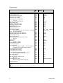
Table of contents
1.
1.1
1.2
1.3
1.4
About this manual
Content of this manual
Overview table
Symbols used
Who is this manual intended for?
4
4
4
4
5
2.
2.1
2.2
2.3
2.4
2.5
Safety
Appropriate use
General safety notes
Regulations and standards
CE labelling
Conformity statement
6
6
6
6
7
8
3.
3.1
3.2
Technical information
AMBIFLO dimensions and connections
AMBIFLO technical data
10
Loss of pressure
AMBIFLO 07-16 circuit diagram
AMBIFLO 20 circuit diagram
14
9
9
3.3
3.4
3.5
11
12
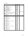
4.
4.1
4.2
4.3
4.4
4.5
Prior to installation
Transport
Installation site
Outdoor installation
Function and construction of an air/water heat pump
AMBIFLO application example
22
16
16
16
17
19
5.
5.1
5.2
Assembly
Heat pump roof
Weather protection grid
24
24
25
6.
6.1
6.2
6.3
Installation
Hydraulic connections to the heating system
Accumulator
Electrical connection (general)
26
26
27
27
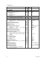
7.
7.1
7.2
7.3
30
30
30
7.4
7.5
7.6
Commissioning
Preparation by the customer
Commissioning (by customer services)
Temperatures for heating and Domestic Hot Water
31
Programming the necessary parameters
Instructing the operator
Checklist for commissioning
8.
8.1
8.2
8.3
8.4
8.5
8.6
8.7
8.8
8.9
8.10
Operation
Operating elements
Indicators
Switching off the heating system
Setting the Domestic Hot Water system
Setting the indoor target values
Displaying information
Error messages
Maintenance messages
Acknowledging the message
Manual operation
34
34
35
35
36
36
36
36
37
37
37
2
31
32
32
369622 09.09
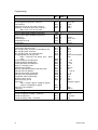
9.
9.1
9.2
9.3
9.4
Programming
Programming procedure
Adjusting parameters
Table of settings
Explanations of the parameter list
10.
10.1
10.2
10.3
Maintenance
Maintenance work
Contact protection
Faults
3
39
39
39
41
63
109
109
109
109
369622 09.09
1.
About this manual
Please read these instructions carefully before operating the device!
1.1
Content of this manual
This manual deals with the installation of AMBIflo air to water heat pumps. The air/water
operating mode may be used. An overview of the various documentation for this appliance
may be found below. Please store all documents at the installation site of the heat pump!
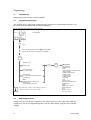
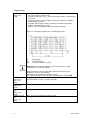
1.2
Overview table
Documentation
Technical information
Installation manual
- Extended information
Operating instructions
Programming and
hydraulics manual
Protocol for
commissioning
Brief instructions
Maintenance manual
Accessories
1.3
Content
- Planning documentation
- Functional description
- Technical data / circuit diagrams
- Basic equipment and accessories
- Application examples
- Tender documentation
- Appropriate use
- Technical data / circuit diagram
- Regulations, standards, CE
- Notes on installation site
- Example of standard application
- Commissioning, operation and programming
- Maintenance
- Commissioning
- Operation
- User settings / programming
- Fault table
- Cleaning / maintenance
- Notes on energy saving
- Table of settings, including all parameters
and explanations
- Other examples of applications
- Reference data for heating system
Intended for
Planners,
operators
- Brief operating guide
- Record of maintenance carried out
- Installation
- Operation
Operator
Operator
Installer
Installer
Operator
Installer
Installer
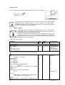
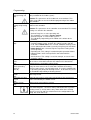
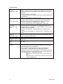
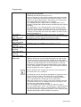
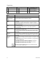
Symbols used
Danger! Disregarding this warning will pose a risk to life and limb.
Risk of electrocution! Non-observance of this warning will pose a risk to life
and limb as a result of electricity!
Warning! Non-observance of this warning will pose a risk to the environment
and the device.
4
369622 09.09
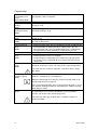
About this manual
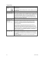
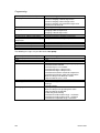
Note/Suggestion: You will find background information and useful hints
here.
Reference to additional information in other documentation
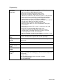
1.4
For who is this manual intended?
This installation manual is intended for the person installing the AMBIflo unit into a heating
system.
Safety
2.
Safety
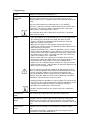
Danger! Please ensure that you observe the following safety instructions.
2.1
Appropriate use
The heat pumps in this series come with electrically operated condensers
and buffer stores (accessories) for heating systems according to EN 14511.
The heat pump is only intended for use as explicitly intended. Where an
application is not in accordance with the information given here, Andrews
Water heaters do not accept responsibility or incur any liability.
This device is not intended to be used by persons with limited physical,
sensory or mental capacity or a lack of experience and/or a lack of
knowledge, unless such a person is supervised and instructed by another
person who takes responsibility for his safety. Children should be supervised
to ensure that they do not tamper with the device.
2.2
General safety notes
Danger! The installation of a heating system poses the risk of considerable
injury to persons or damage to the environment and to objects. Heating
systems may thus only be installed by specialised companies and must be
commissioned by the manufacturers commissioning Engineers
The adjustment, maintenance and cleaning of the device may only be carried
out by a qualified person!
5
369622 09.09
The accessories used must be in accordance with the technical regulations
and must be approved by the manufacturer for the specific device. Only
original spares may be used.
Customers are not permitted to undertake conversions or adjustments of the
device, as this will endanger lives and may result in damage to the device.
The warranty will become invalid should this guidance not be adhered too.
Risk of electrocution! All electrical work association with the installation of
the AMBIflo must be carried out by a qualified electrician!
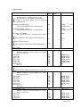
2.3
Regulations and standards
Apart from the general technical standards, the relevant standards, regulations, ordinances
and guidelines must be observed:
DIN EN 378 (Parts 1-4); cooling systems and heat pumps – safety and
environmentally relevant requirements
DIN 4109; sound insulation in high-rise buildings
DIN EN 12828; safety equipment for heating systems
EN 14511; heat pumps with electrically operated condensers for indoor heating
EnEV – energy savings ordinance
DIN 18380; heating systems and central water-heating systems (VOB)
DIN EN 12831; heating systems in buildings
DIN 4753; water-heating systems for drinking and industrial water
DIN 1988; technical regulations for Domestic Hot Water installations (TRWI)
DIN VDE 0100; EN 50165; electrical design of non-electrical devices
DIN VDE 0116; electrical equipment for heating systems
VDE: EN 60335 and EN 50366 heating system ordinance; various state ordinances
6
369622 09.09
Safety
-
Regulations of local energy supply companies
Notification requirement (or approval ordinance)
ATV data sheet M251 of the Waste Water Association
2.4
CE Marking
CE marking means that all guidelines according to the CE standards have been adhered to in
the design and manufacture of the AMBIflo unit (see conformity statement).
Adherence to the safety requirements according to Guideline 89/336/EWG can only be
guaranteed if the heat pump is operated as intended.
The environmental conditions according to EN 55014 must be adhered to.
Operation is only permitted once a proper cover has been fitted.
The appliance must be earthed
When exchanging parts, only original spares as prescribed by the manufacturer may be used.
7
369622 09.09
Safety
2.5
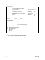
Conformity statement
BRÖTJE HEIZUNG
CE
Declaration of conformity
Air/water heat pump
Product
Trademark
AMBIflo
Type, model
AMBIFLO 16, AMBIFLO 20
EU directives
89/392/EWG or 98/37/EC
89/366/EWG, 73/23/EWG
97/23/EG
Standards
DIN EN 14511 -1/-2/-3/-4,
DIN EN 378 -1/-2/-3/-4, DIN EN 60529, DIN
EN 294, DIN EN 60335 -1/A2 -2 -40,
DIN EN 292/T1 T2, DIN EN 349,
DIN EN 55014-/T1 T2, DIN EN 61000-3-2 / 0303
The manufacturer hereby declares the following:
The duly labelled products meet the requirements of the guidelines and standards as listed.
They concur with the tested prototype, but no specific characteristics can be guaranteed. The
manufacturing process is subject to the monitoring procedures as listed. The product
mentioned may only be used for installation in hot water heating systems. The system
manufacturer must ensure that the regulations for installation and operation of the device are
adhered to.
AUGUST BRÖETJE GmbH
(Signature)
Head of Development
Rastede, 01/07/09
8
(Signature)
Head of Trials
August BRÖTJE GmbH
August- BRÖTJE -Straße 17
26180 Rastede
P.O. Box 13 54
26171 Rastede
Tel (04402) 80-0
Fax (04402) 8 05 83
http://www.broetje.de
Executive director:
Dipl.-Kfm. Sten Daugaard-Hansen
Oldenburg District Court
HRB 120714
369622 09.09
Technical information
3.
Technical information
3.1
AMBIflo dimensions and connections
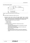
Fig. 1: Dimensions and connections
1
2
3
Heating flow
Ø 1" (AMBIFLO 16), Ø 1¼" (AMBIFLO
20) flexible. The hydraulic and electrical
connections can all be located on the left
or right hand side of the heat pump.
Heating flow
Ø1" (AMBIFLO 16), Ø 1¼" (AMBIFLO 20)
flexible 9. A minimum distance of 800
mm must be maintained at the front of
the heat pump for maintenance
purposes. A minimum distance of 500
mm is required on the free side opposite
the air outlet.
Condensation water outlet Ø ¾", flexible
4
5
6
7
8
9
Air inlet (at the back of the device),
For details, see air connections
Air outlet (at left, right or top),
For details, see under air connections
Internal electrical panel
Electrical connections
Adjustable legs, absorbing structureborne noise
A minimum distance of 800 mm must be
maintained at the front of the heat pump
for maintenance purposes. A minimum
distance of 500 mm is required on the
free side opposite the air outlet.
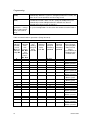
Table 1: Dimensions
AMBIflo
16
20
9
Width
a
Height
b
Depth
c
1195
1195
1675
1695
750
880
Bottom Top
Hydraulic connections
height
height
i
j
k
t
d
e
all dimensions in mm
575
1060
210 300 390 100
670
975
230 385 545 110
Legs
q
p
300
300
40
50
369622 09.09
Technical information
3.2
AMBIflo technical data
Model
Heating system
Heat output
Power consumption
COP
Condenser
Maximum power consumption
Starting current with smooth starter
Power intensity with locked rotor (LRA)
Power connection
1)
Fuse (inert)
Max
speed:fan/Q-pump
(Prog.No.3010)
2)
Smooth starter settings
Water/heat exchanger
Hydraulic connections
Water content, incl. connection
pipes
Nominal volume flow: heating
system
Pressure loss: heating system
Nominal volume flow: cooling
system
Pressure loss: cooling system
Air/heat exchanger/fan
Volume flow
Pressure available
Power consumption of fan
Nominal current consumption of
fan
Cooling agent
Cooling agent filling
Cooling circuit oil
Oil volume
Total weight of heating pump
3)
Sound pressure level
4)
Outdoor installation
AMBIflo
kW
kW
-A
A
A
V-f-Hz
A/T
%
A
16
20
15.1
19.9
4.0
6.3
3.7
3.2
Scroll hermetically
14.0
17.0
36.0
40.0
74
99
400-3-50
20
20
100
90
13.5
16
Material: AISI 316 chromium steel,
1.4401
R
1"
1¼"
l
3.4
4.9
l/h
1 461
1 754
kPa
5.5
3.7
l/h
2 502
3 013
kPa
15.9
11.9
3
m /h
Pa
kW
A
5 000
55
0.43
1
-kg
-l
kg
1.89
277
dB(A)
40.3
3.7
6 300
120
0.96
1.9
R407C
Ester oil
5.4
4.1
337
44.1
1) The data given for the fuses only take into account the power consumption of the heat
pump. Any additional heating has not been taken into account.
2) for AMBIFLO 16: Type 150-C16NBD; for AMBIFLO 20: 150-C25NBD
3) The sound pressure level refers to the measurements taken by the Federal laboratory in
Dübendorf (EMPA)
4) An open distance of 10 m.
10
369622 09.09
Technical information
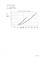
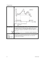
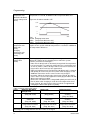
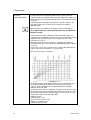
3.3
Loss of pressure
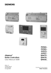
Fig. 2: AMBIflo pressure loss
Loss of pressure: water/heat exchanger
Loss
of
pressure
[kPa]
Flow [l/h]
11
369622 09.09
Technical information
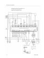
3.4
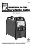
AMBIFLO 16 circuit diagram
Flow connection for K25 electrical heater:
Key:
ATF
BE
F3
F1
FB
HD
HGF
K25
KSP
M19
ND
QAF
QEF
S2
R1
R25
WRF
WVF
X0
X1
X2
VWV
1)
*)
External temperature sensor QAC34
Operating unit
Fuse 10A T
All phase circuit breaker
Remote control *)
High-pressure switch
Hot gas sensor B81
Power switch for flow heating R25
Condenser pump *)
Fan
Low-pressure switch
Source output sensor B92
Source input sensor B91
Main switch 1)
Oil tank heating
Flow insert for electrical heater
Heat pump reflux sensor B71
Heat pump flow sensor B21
Terminal strip for main supply
Terminal strip for consumers
Terminal strip for fan + oil tank heating
Four-way valve
At the factory
Accessories
Condenser
Not connected
at factory
The main switch S2 has not been installed in the heat
pump and must be provided externally (by the
customer), according to local regulations / national
standards. Non-observance of these regulations may
result in injury to persons. DANGER
Externally
Important!!!: The
two red link plugs
L3-F3 and N-N1
must be removed.
Pipe dimensions according to local
situation Please note phase sequence
Customer back-up fuse is
recommended.
The
installing electrician takes
responsibility.
AMBIFLO
+
R25
3P+N+PE
AMBIFLO 7A
20A, C'
Pipe dimensions according to
local situation Please note phase
sequence
The main switch S2 has not been
installed in the heat pump and
must be provided externally (by
the customer), according to local
regulations / national standards.
Non-observance
of
these
regulations may result in injury to
persons. DANGER
AMBIFLO 10A + 12A
Customer's control panel
AMBIFLO7-16A power connection, provided that the energy provider
allows all consumers (scroll condenser, additional heating, controls, etc.) to
be operated at a single tariff and that the heat pump is not locked at the
power plant lock for all
phases.
12
Customer's control panel
AMBIFLO7-16A power connection, provided that the energy provider allows for separate
supplies (scroll condenser and additional heating) and/or the WP tariff is locked for all phases
at the power plant lock.
369622 09.09
Technical information
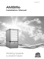
Power plant lock: contact open = power plant lock active
Low-tariff: contact closed = low tariff release
Low pressure = shown as pressure-free
High pressure = shown without overpressure
Please note: Indicator bus should only
be wired to 5-pin X30 (Bus BE) if
length < 10m; otherwise to 3-pin "FB".
13
369622 09.09
Low tariff
Power plant lock
Heat pump controller ISR – RVS41.813
Technical information
x3.5
Key:
ATF
BE
F3
F1
F19
FB
HD
HGF
K25
KSP
M19
ND
QAF
QEF
S2
R1
R25
WRF
WVF
X0
X1
X2
VWV
1)
*)
AMBIFLO 20 circuit diagram
External temperature sensor QAC34
Operating unit *)
Fuse 10A T
All phase circuit breaker
Fan fuse
Remote control *)
High-pressure switch
Hot gas sensor B81
Power switch for flow heating R25
Condenser pump *)
Fan
Low-pressure switch
Source output sensor B92
Source input sensor B91
Main switch 1)
Oil tank heating
Flow insert for electrical heater
Heat pump reflux sensor B71
Heat pump flow sensor B21
Terminal strip for main supply
Terminal strip for consumers
Terminal strip for fan + oil tank heating
Four-way valve
At the factory
Accessories
The main switch S2 has not been installed in the heat
pump and must be provided externally (by the
customer), according to local regulations / national
standards. Non-observance of these regulations may
result in injury to persons. DANGER
Externally
Important!!!: The two
red link plugs L3-F3
and N-N1 must be
removed
Pipe dimensions according to local
situation . Please note phase sequence
Pipe dimensions according to local
situation.
Please note phase sequence
Customer back-up fuse
is recommended. The
installing electrician
takes responsibility.
The main switch S2 has not been
installed in the heat pump and must
be provided externally (by the
customer), according
to local
regulations / national standards. Nonobservance of these regulations may
result in injury to persons. DANGER
AMBIFLO 20 A
Customer's control panel
Customer's control panel
AMBIFLO20A power connection, provided that the energy provider allows
all consumers (scroll condenser, controls, etc.) to be operated at a single
tariff and that the heat pump is not locked at the power plant lock for all
phases.
14
AMBIFLO20A power connection, provided that the energy provider allows for separate supplies
(scroll condenser and additional heating) and/or the WP tariff is locked for all phases at the
power plant lock.
369622 09.09
Technical information
Power plant lock: contact open = power plant lock active
Low-tariff: contact closed = low tariff release
Low pressure = shown as pressure-free
High pressure = shown without overpressure
Please note: Indicator bus should only
be wired to 5-pin X30 (Bus BE) if
length < 10m; otherwise to 3-pin "FB".
15
369622 09.09
Low tariff
Power plant lock
Heat pump controller ISR – RVS41.813
369622 09.09
Further examples of applications (mixer heating circuits, connection to solar heating
system, etc.) may be found in the software and hydraulics manuals.
Please note: The heat pump must be
protected by a circuit breaker with an allphase switch (not by 3 individual fuses)!!
The diagram on the right must be used.
Local regulations must be observed.
Customer's control panel
Fuses according to WP type:
AMBIFLO
6B
–
20A, C'
AMBIFLO
14B
+
The AMBIFLO6-16B power supply circuit
diagram in the installation instructions must
be taken into account.
Parameters to be set:
Menu Point
Function
"I" configuration 5700
Factory setting
Setting
1
Only for AMBIFLO6-16A
"I" configuration 5890
Key:
ATF
F10
KSP
S2
*)
1)
QX1 relay output
External temperature sensor QAC34
All-phase circuit breaker 1)
Condenser pump *)
Main switch 1)
Accessory
Factory setting
Electrical insert 1
K25 supply
ISR - RVS41.813 heat pump controls
Power plant lock:
Contact closed for
Power
BSW release plant
gate
12B
16B
Prior to installation
16
Fig 7: Connection plan
Technical information
Prior to installation
4.
Prior to installation
4.1
Transport
Upon delivery of the heat pump, it must be checked for transport damage and complete
delivery according to the order confirmation. Where material is damaged or missing, the
transport company must be immediately notified in writing.
Care must be exercised during transport, set-up and preparation or when handling the unit so
as not to cause damage.
Please ensure that load cables, straps or chains cannot damage the heat pump.
Please note! The heat pump may not be tilted by more than 15° from its vertical
axis.
For transport purposes, the heat pump is fixed on a pallet at the factory and covered in film to
protect it against scratches. The packaging may only be removed once the heat pump has
reached its final location.
Transport notes
To avoid transport damage, the packaged heat pump, together with its wooden pallet, must
be transported to its final installation site by pallet truck or push cart.
-
-
Secure the heat pump on the push cart to prevent sliding
Do not use the components or pipes of the cooling circuit, the heating system and the
heat source for transport purposes or lifting of the unit.
Take the weight of the heat pump into full account when lifting the unit.
To avoid any damage to the water pipes and electrical wiring, please note their
position and protect them accordingly
Only lift and transport the heat pump by holding on to the base of the unit.
4.2
Installation site
-
The pump must be installed with care and accuracy.
Please ensure that you have obtained the necessary permits to operate the heat
pump.
Once it reaches its final installation site, the heat pump must be carefully unpacked
and taken off the pallet, taking care not to subject it to any shocks.
Both the air inlet and outlet must be kept clean and must not be subject to blockage or
infiltration by snow, leaves, vegetation, implements or any other item likely to restrict the air
flow through the unit. The prescribed minimum distances must be observed to ensure the air
flow is not obstructed and to give access for maintenance (see page 9).
The air inlet must be protected against ingress from corrosive substances such as
ammonia, chlorinates, etc.
17
369622 09.09
Prior to installation
The AMBIflo heat pump is very quiet in operation, however, in the knowledge
that noise perception is very subjective, the pump should not be set up near
a window, bedroom or leisure site (terrace, swimming pool deck, etc.). A
sufficient distance to the adjoining properties should be observed. It is not
recommended to set up the pump in a wall niche (possible echo or air
blockage).
Instructions for outdoor installation
The heat pump should be placed on a flat/level and firm surface with the correct
load carrying capacity. It is advisable to supply a foundation such as concrete or a
slab, taking the potential depth of any snow into account, so that the base of the
pump will never be subject to snow.
The flow and return pipes should cover as short a distance as possible and must be well
insulated to avoid heat loss. The condensation water outlet must be insulated and protected
against frost and the water should be channelled into a closed outlet via a siphon with a
minimum height of 100 mm. The outlet pipe must not have any constrictions and must have a
sufficient gradient to ensure an easy flow. The control unit must be installed indoors
(temperature range +5°C to +40°C).
The wall apertures for the flow and return pipes, as well as the electrical cables
must be constructed according to the regulations. Electrical cables, in particular,
must be flexible, with mains voltage (230 or 400V) and low voltage (sensor and
control) cables shielded from each other.
18
369622 09.09
4.3
Outdoor installation
Base
The base should project approx 50 mm beyond all sides of the heat pump and be sufficiently
high enough to account for snow and water ingress.
Prior to installation
Fig. 3: Dimensions of air inlet
1
2
Heating flow Ø 1" (16), Ø 1¼" (AMBIFLO
20) flexible. The hydraulic and electrical
connections can all be located on the left
or right of the heat pump.
Heating flow Ø1" (16), Ø 1¼" (20)
flexible.
3
4
Condensation water outlet Ø ¾", flexible
Air inlet (ZA AMBIFLO accessory)
5
6
7
8
Air outlet (ZA AMBIFLO accessory),
either right
or left
Internal electrical control panel
Hydraulic and electrical connections,
electrical cables – extra-low voltage
shielded from 400V and 230V cables.
Adjustable legs, absorbing structureborne noise
9
Protective roof (ZA AMBIFLO accessory)
10
Pump base, minimum height 300 mm,
taking the depth of local snow falls into
account
12
Wall aperture with seal tilted towards the
inside (made of PE, internal diameter
150 mm)
Control unit for wall installation (included
in delivery), siphon for condensation
water at a minimum height of 100 mm.
A minimum distance of 800 mm must be
maintained at the front of the heat pump
for maintenance purposes. A minimum
distance of 700 mm (o 500 mm for Set
AAS) must be kept at the back (on the
suction side). A minimum distance of
500 mm is required on the free side
opposite the air outlet, while a minimum
distance of 2 000 mm is required on the
outlet side.
13
Table 1: Dimensions
Width a Height without Depth
Bottom
Top height without
Pump base
protective roof c
height
protective roof e
a1
c1
h1
b
d
16
1195
1675
750
575
1060
1295
850 300
20
1195
1695
880
670
975
1295
980 300
AMBIFLO accessory: incl. 2 weather protection grids, control panel cover and protective roof
AMBIflo
19
369622 09.09
Legs
q
40
50
Fig 4.
Alternative condensation water
outlet via drainage shaft is possible.
Drainage pipe insulation at least 3
cm.
Minimum size of drainage shaft
H = 50 cm
W = 50 cm
D = 50 cm
Water-tight empty pipe (plastic) to be installed 800 to 1000
mm below the ground by the customer, at a gradient of 2%
towards the building.
Only 45° brackets should be used.
4.4
Function and construction of an air/water heat pump
The high-quality AMBIFLO air/water heat pump removes heat from the outdoor environment,
channelling it to the heating system at a higher temperature level. The heat pump can be installed in
newly constructed or existing heating systems, taking into account the capacity limitations (see
Technical Data).
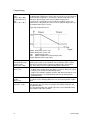
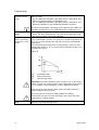
Operating method of the heat pump
Fig 5. Diagram of a heat pump
Q = heating power
Condenser
Expansion valve
E = electrical power
Compressor
Evaporator
Condenser
COP =
20
Q
--E
369622 09.09
Prior to installation
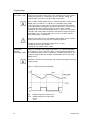
Optimised defrosting
When the outdoor temperature drops below 7°C, frost will form on the air/heat exchanger's
evaporator. This will result in the formation of ice and will consequently reduce heat exchange
and thus the degree of efficiency of the heat pump.
To remove this frost or ice, the evaporator must be defrosted. This is done at
AMBIFLO by reversing the cooling circuit, but this is not a cost-effective
process, as during defrosting the heat pump provides no energy, but still
consumes power. As the frost formation depends on the humidity level of the
air, however, it is always necessary.
Instead of putting the device through a defrosting process at regular intervals, AMBIFLO
determines the correct defrosting time by using advanced logic, with various performance
parameters being defined in the cooling circuit. Thanks to this process, defrosting is rarely
necessary in winter – a great advantage.
Low-noise operation
The AMBIFLO air/water heat pump has very low sound emissions when installed outdoors.
This is possible thanks to the high-performance fan, the very advantageous air-channelling
process, the triple bearings of the mobile mechanical components as well as the sound-proof
insulation of the cover.
General notes
The pipes and air channels should be kept as short as possible and the pipe
guides should be such that the loss of pressure and heat can be kept as low as
possible. Poor or wrongly dimensioned pipes can cause damage to the heat
pump.
Systems with a buffer storage tank must have a flow volume via the heat distributor that is
lower than the flow volume of the charging circuit (heat pump store) to prevent any reflux via
the buffer store. This would have an adverse effect on the economic efficiency of the system
and adversely affect the smooth functioning of the heat pump.
21
369622 09.09
Prior to installation
Prior to installation
4.5
22
AMBIFLO application example
369622 09.09
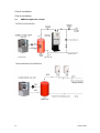
Prior to installation
Fig 7: Connection plan
Please note: The heat pump must be protected
by a circuit breaker with an all-phase switch
(not by 3 individual fuses)!!
The diagram on the right must be used.
Customer's control panel
Local regulations must be observed.
AMBIFLO 16B
The AMBIFLO16B power supply circuit diagram
in the installation instructions must be taken
into account.
Power plant lock:
Contact closed for Power
BSW release
plant
gate
Fuses according to WP type:
25A,
Parameters to be set:
Menu point
"I" configuration 5700
Function
Factory setting
Setting
1
Only for AMBIFLO6-16A
"I" configuration 5890
QX1 relay output
Electrical insert 1
K25 supply
Network
ISR - RVS41.813 heat pump controls
Key:
ATF
F10
KSP
S2
*)
1)
External temperature sensor QAC34
All-phase circuit breaker 1)
Condenser pump *)
Main switch 1)
Accessory
Factory setting
Further examples of applications (mixer heating circuits, connection to solar heating system,
etc.) may be found in the software and hydraulics manuals.
23
369622 09.09
Assembly
5.
Assembly
5.1
Heat pump roof
Pre-rolled opening for air/water heat pump installed outdoors
There is a pre-rolled opening (1) at the bottom of the pump system, behind
the electrical control panel, through which the pipes pass into the ground.
Where a heat pump is installed outdoors, we recommend that you use this
duct. The heating pipes, the condensate connection and the electrical cables
all pass through this opening. Please also take into account the plan for the
base with the necessary aperture.
Assembly of the heat pump roof
-
The metal roof is to be fixed to the lower edge of the metal all around the
circumference, using the sealing tape (2) provided. This prevents the formation of
cooling bridges / condensation water.
Remove the screws on the roof of the heat pump cover.
Turn the metal roof and fix it to the top of the cover using the screws (3) provided.
Make use of the existing 4 holes (4).
Fig. 8
24
369622 09.09
Assembly
5.2
Weather protection grid
The two weather protection grids (on the inlet and outlet side) must be fixed to the interior
frame of the cover. This can be done with the aid of an Allen key (Size 3) or a battery-driven
screw driver.
The outlet side may be on the left or right. The outlet grid must be used when the system is
installed outdoors.
Where the weather protection grid is to installed (outdoor installation), the air sensor (5) must
be pulled out of the grid.
Fig. 9
25
369622 09.09
Installation
6.
Installation
All transport safety devices must be removed before operation. The regulations and diagrams
must be carefully followed.
The accessories must be installed by an expert (heating system technician)
according to the instructions for installation included.
The noise emanating from a heat pump of this type is very low, due to the
three-step, sound-absorbing bearings used for the movable components and
the sound insulation cover. The effective sound level also partially depends on
the sound proofing or reflection of the surrounding materials, as well as the
possibility of having the sound Range as structure-borne noise.
Pipes and electrical cables must be attached to the wall and not to the heat
pump. All these connections must be joined to the heat pump via flexible
connections so that they can swing freely, especially when the condenser or fan
starts up. This is the only way in which the transmission of structure-borne
noise can be avoided.
6.1
Hydraulic connections to the heating system
The pipes may be installed on the left or right side and are connected inside the heat pump.
The pipes must be such that any loss of pressure at nominal power will not exceed the
pressure available, as this would result in a reduction in the capacity of the heat pump. The
heating circuit pipes should not be over tightened. The pipes must also be sufficiently
insulated to avoid unnecessary heat loss or the formation of condensation, which could
damage the pipes or the installation.
The system must be thoroughly flushed before being connected to the heat
pump.
Condensation outlet
The condensation outlet should be as close as possible to the connection of the heat pump.
To avoid having environmental air or waste air sucked into the heat pump, the condensation
outlet must be connected to the heat pump via an air-tight syphon at a minimum height of 100
mm. The condensation outlet may not be constricted and must have at least a 2% incline
along its entire length, so that the water can run off easily.
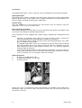
Exchanging the hydraulic and electrical connections
The pipes are normally connected to the left of the heat pump. Where the right side is
preferred, these panels (1 and 2) can be exchanged for the panels on the opposite side. The
pipes and cables inside the heat pump are pulled over to the other side and slotted through
the aperture in panel 1 (fig. 10).
26
369622 09.09
Installation
Fig. 10
6.2
Accumulator
When the heat pump is operated with a buffer storage tank, Andrews Water Heaters
accumulators of the Solar series are recommended.
6.3
Electrical connection (general)
Risk of electrocution! All electrical work associated with the installation may
only be carried out by a person trained as an electrician!
- Power supply 1/N/PE: AC 230 V +6% -10%, 50 Hz
- Power supply 3/N/PE: AC 400 V +6% -10%, 50 Hz
During installation, the IEE and local regulations for England and Wales, or alternatively the
relevant regulations for all other countries must be observed. The power supply may have a
maximum tolerance of 2% for current intensity and 10% for voltage. The heat pump may not
be connected if the difference between the phases exceeds 2%. Any operation outside the
abovementioned limit values will result in the warranty being nul and void. Where necessary,
the local power supplier should be contacted.
All electrical connections must be carried out in such a way as to guarantee correct polarity.
An accessible plug or a permanent connection should be used.
It is recommended to place a main switch before the AMBIFLO to switch off all poles and to
ensure a contact opening width of at least 3 mm. All connected components must be in
accordance with the IEE and the connection cables should not be subjected to tensile stress.
Cable grips
All electrical cables must be placed into the cable grips of the control unit and connected in
accordance with the circuit diagram.
Circulation pumps
N max
The permitted current load per pump output will be I
= 2A (max. current consumption 6A).
Connecting the sensors / components
Risk of electrocution! The circuit diagram must be taken into account!
Accessories should be installed and connected in accordance with the
instructions included. Plug in the mains and check the grounding.
27
369622 09.09
Installation
The outdoor temperature sensor is enclosed. See circuit diagram for connection instructions.
Cable replacement
All electrical cables, with the exception of the main power supply cable, must be replaced with
Andrews Water Heaters special cables, where required. Only cables of the type H05VV-F are
to be used when replacing the main power supply cable.
Contact safety
Once the AMBIFLO has been opened, the cover panels must be replaced, using the
appropriate screws, to ensure contact safety.
Notes on electrical controls
The internal cabling for the heat pump has been carried out at the factory in accordance with
the electrical circuit diagram accompanying the device.
The heat pump has been equipped with a power supply, containing the components listed
below:
Externally, an automatic safety switch or a 3-phase insert fuse with a neutral wire
must be provided, designed according to the technical specifications.
The low-voltage cables (control unit) may not be channelled through the same cable
ducts as the power supply cables.
The outdoor temperature sensor of the control unit must be attached to the outside
wall of the building, where it may not be affected by either the afternoon sun or any
other foreign heat source (open window, chimney, etc.). The preferred alignment
should be north or north/east.
In the event of remote control, the room inlet must be located in a reference room (for
example the living room), where it cannot be influenced by any external heat sources
(such as chimneys, the sun, a fireplace, heaters or air ducts).
Cable connections
1.
Insertion of 3 x 400V power cable
2.
Insertion of low-voltage / sensor cable
3.
Fastening screws
Loosen the screws (3) and push the metal cover forwards. This facilitates the insertion of the
low-voltage cables (2). Once the cables have been inserted, push the cover back again and
refasten the screws (3).
28
369622 09.09
Installation
Fig. 11 Electricity box
1.
2.
3.
4.
5.
6.
7.
29
RVS heat pump control unit
Smooth starter and alternating current relay
230V microfuse
Electrical contactor
3x400V main power supply
Power plant lock / flow monitor
Fan connection
369622 09.09
Commissioning
7.
Commissioning
Danger! An accredited heating technician must commission the system! The
heating technician will check the leak-tightness of the pipes, the proper
function of all control and safety devices and measure the combustion values.
There is a risk of considerable injury to persons or damage to objects or the
environment in the event of improper execution!
All systems must be commissioned by an authorised customer service centre, failing which
the contractually stipulated warranty will expire. The customer service centre will only handle
the commissioning process, but not the connection of the heat pump or any other work.
Our participation in the commissioning process does not mean that we take any
responsibility for the type of planning and the installation of the system. Our
participation will be restricted to the technical functionality of our product.
7.1
Preparation by the customer
The following points must be checked before commissioning:
1.
The heat pump is electrically and hydraulically complete and has been duly
connected.
2.
All external components required for operation, such as circulation pumps, three-way
valves, sensors, etc. have been fully and duly connected.
3.
The hydraulic connections have been fully and duly connected.
4.
All sensors have been properly wired up, shielded and are in the correct place
according to the relevant system diagram.
5.
The heating system has been professionally set up and flushed, filled, vented and
checked for leaks according to the regulations.
6.
Check the safety valves on the water pipes.
7.
Check the mains voltage and frequency.
8.
Connect the fuses according to the values given on the identification plate and in the
technical data sheets.
Please note! The fuse for the compressor must cover all wires (do not use 3
individual fuses)!
9.
10.
11.
12.
Check the torque of the screws used to attach the electrical conductors.
Connect the terminals of the heat pump control unit (inputs and outputs) according to
the terminal plan for the object in question.
Check the water filling level and pressure of the evaporator and condenser.
Open the check valves in the water circuits.
7.2
Commissioning (by customer services)
The device can be switched on once all the above mentioned points have been observed.
The presence of the following persons is required during commissioning:
The planner, who must specify the operating parameters.
The technician, who is responsible for the functionality and settings of the hydraulic
system.
The system operator (the customer or his representative), who is familiarised with the
system and trained in the operation thereof during the commissioning process.
30
369622 09.09
Commissioning
Where commissioning is requested without all these conditions being met, Andrews Water
Heaters will take no responsibility for any system operating problems. The system is then
operated at the user's own risk and responsibility. The following points must be observed or
checked:
1.
2.
3.
4.
5.
6.
-
Hydraulic circuits: Check concurrence with the documentation provided.
Check the electrical connections and fuses.
Check the terminal allocation at the heat pump control unit.
Configure the control unit parameters according to the presettings given under Prog.
No. 5700.
Carry out inlet and outlet tests and check whether the water circuits have been vented
and filled with water at the correct pressure.
Commission the heat pump and check the operating values (according to the
"Technical Data"):
The current consumption of the compressor may not exceed the values given in the
"Technical Data" table.
Check the temperature values in the heating circuit.
Check the hot water flow (using the temperature difference between the water inlet
and outlet at the condenser)
3
Flow volume (m / h) =
Heating capacity (kW) x 0.86
----------------------------------------------------3
Flow volume (m /h) = Temp.difference (°C)
7.
Use the operating mode button for heating operation
on the control unit to select the operating mode "Automatic
operation"
.
8.
Set the desired room temperature, using the rotary
button of the control unit.
7.3
Temperatures for heating and Domestic Hot Water
When setting the temperatures for the heating and Domestic Hot Water systems, the
information in the "Programming" section must be taken into account.
It is recommended that the Domestic Hot Water temperature be set to 45°C.
7.4
Programming the necessary parameters
The control parameters normally do not need changing (application example). Only the
date/time and possibly the timer programmes will have to be set.
The parameter settings are described in the "Programming" section.
31
369622 09.09
Commissioning
7.5
Instructing the operator
Instruction
The operator must be duly instructed in the operation of the heating system and the function
of the protective devices. In particular, the following must be pointed out to him:
-
The state of the cover is to be checked.
The fastening of the outer cover is to be checked.
To protect the paintwork, no objects should be leaned against or placed on top of the
device.
The external parts of the heat pump can be wiped down with a moist cloth and a
commercial cleaning agent (use a non-abrasive cleaning agent with a solvent!).
Controls to be carried out by the operator himself:
Pressure check at the manometer
Leaks in the hot water circuit.
An authorised service centre must be entrusted with the maintenance work
(oxidation products may form when oxygen penetrates into the heating circuit).
-
The mains cable between the heat pump and the switch cabinet may not be torn or
worn or have any other kind of damage that could adversely affect the insulation. An
authorised service centre is responsible for maintenance work.
Inspections and cleaning at regular intervals may only be carried out by accredited
gas technicians.
Documentation
Any documentation pertaining to the heating system is handed over with the
instructions to store it in the room in which the heat pump has been installed.
The commissioning checklist requires confirmation of receipt and a legally valid
signature by the operator: only components tested in accordance with the relevant
standards have been used. All components have been fitted according to the
manufacturer's instructions. The overall system is in accordance with the standards.
7.6
1.
2.
3.
4.
5.
6.
7.
8.
9.
32
Checklist for commissioning
Have all cables and connections been checked for
leaks?
Have all hot water circuit pipes been bled?
Has the operating pressure been checked?
Do the pumps run freely?
Fill up the heating system
Water additives used
Has the current consumption of the condenser been
measured?
Temperatures:
in the heating circuit
Check flow:
hot water flow
mbar
...................................
mA
....................................
....................................
°C
3
m /h
....................................
....................................
369622 09.09
Commissioning
10.
Construction to be dried
out
11. Functional test
Heating system
Domestic Hot Water
system
12. Programming
Time / date
Comfort target value for
heating circuit ½
Nominal target value for
Domestic Hot Water
Automatic daily time
program
13. Leak-tightness tested during operation?
14. Operator instructed?
15. Documents handed over?
All components used have been checked and labelled in accordance
signature
with the relevant standards. All system components have been fitted
stamp
according to the manufacturer's instructions. The total system is in
accordance with the standards.
33
Only for new constructions
°C
....................
°C
....................
o'clock
....................
Date
/
Company
.................................
369622 09.09
Boiler Temperature
Operation
8.
Operation
8.1
Operating elements
Fig. 12: Operating elements
1.
2.
3.
4.
5.
6.
7.
8.
9.
34
Operating mode button for Domestic Hot Water system
Control unit
Operating mode button for heating system
Display
OK button (acknowledgement)
Information button
Turning button
ESC button (termination)
No function
369622 09.09
Operation
8.2
Indicators
Fig. 13: Display symbols
Meaning of the symbols shown
Maintenance message
Heating to comfort target value
Heating to reduced target value
Heating to frost protection target value
Current process
Holiday function active
Error message
INFO Information level active
PROG Settings level active
ECO
Reference to heating circuit 1 or 2
8.3
Heating switched off (summer/winter
automatic switch or automatic heat
limit active)
Switching off the heating system
The user can switch between the operating modes for the heating
system by using the operating mode button for the heating
system. The setting selected is shown by a bar underneath the
relevant operating mode symbol.
Automatic operation
The following conditions apply to automatic operation
Heating operation according to the time program
-
:
or
according to the time program
Temperature target values
Protective functions (system frost protection, overheating protection) active
Summer/winter automatic switch (automatic switching between heating operation and
summer operation once a specific environmental temperature has been reached)
Automatic daily heat limit switch (automatic switching between heating operation and
summer operation once the environmental temperature exceeds the target value).
Permanent operation
The following conditions apply to permanent operation
35
or
:
369622 09.09
Operation
-
Heating operation without timer program
Protection functions active
Summer/winter automatic switch not active during permanent operation with comfort
target value
Automatic daily heat limit switch not active during permanent operation with comfort
target value.
Safety operation
The following conditions apply during safety operation
No heating operation
Temperature depends on frost protection
Protective functions active
Summer/winter automatic switch active
Automatic daily heat limit switch active
8.4
:
Setting the Domestic Hot Water system
- Switched on: The Domestic Hot Water will be produced
according to the switch program selected.
- Switched off: The Domestic Hot Water system has been
deactivated.
8.5
Setting the indoor target values
-Comfort target value
.
The comfort target value must be set directly on the turning
button, i.e. either higher (+) or lower (-).
- Reduced target value
. The reduced target value is set as
follows:
- Press the acknowledgement button (OK).
- Select a heating circuit.
- Select a parameter reduced target value.
- Set the reduced target value using the turning button.
- Press the acknowledgement button (OK) again.
Return to the basic display from the programming or information level by pressing
the operating mode button for the heating circuit.
8.6
Displaying information
Various temperatures and messages can be called up by pressing the
information button, including the following:
indoor and outdoor temperature
error or maintenance messages.
Where there are no errors or maintenance messages, this information will not be
shown.
8.7
Error messages
appears on the display, a system fault has occurred. Further
If the error symbol
information may be obtained by pressing the information button (see Error Code Table).
36
369622 09.09
Operation
Step
1
8.8
Function
Calling up further information on the error message (see Error Code
Table).
Maintenance messages
When the maintenance symbol
appears on the display, there is either a maintenance
message or the system is in special operating mode. Further information can be called up by
pressing the information button (see Maintenance Code Table).
Step
1
Function
Calling up further information on the maintenance message (see
Maintenance Code Table).
The maintenance message has not been activated as a factory setting.
8.9
Acknowledging the message
The end user has the option of acknowledging a maintenance message. The message will
then be deleted in the entire system
Step
1
Function
Calling up the end user settings level
2
Calling up maintenance/service.
3
Calling up the acknowledgement message (Prog. No. 7010)
4
5
8.10
Heating
circuit
operating
mode button
Selecting parameter "1" (acknowledgement)
Quitting the programming mode.
Manual operation
Activating manual operation. During manual operation, the boiler is set to the target value for
manual operation. All pumps are switched on. Further requirements such as Domestic Hot
Water, for example, are ignored!
Step
1
Function
Calling up the end user setting level.
2
Calling up maintenance/service.
3
Calling up manual operation (Prog. No. 7140).
37
369622 09.09
Operation
Step
4
Function
Selecting the "On" parameter.
5
38
Heating
circuit
operating
mode
button
Quitting the programming mode.
369622 09.09
Programming
9.
Programming
Programming must take place after installation.
9.1
Programming procedure
The selection of the setting levels and menu points for end users and heating technicians is to
be carried out in accordance with the following diagram:
Fig. 14: Selection of the setting levels and menu points
Basic display
Press
Press the information button for approx. 3 seconds
until the words "End User" appear on the display
Setting levels:
End user (E)
Commissioning (I)
incl. end user (E)
Technician (F)
incl. end user (E) and maintenance
technician (I)
OEM
includes all other setting levels
and has been
protected with a password
Depending on the selection of the setting level and the
program, not all menu points may be visible!
9.2
Menu points:
Time and date
Operating unit
Radio
Timer program for heating circuit 1
Timer program 4
Holiday heating circuit 1
Heating circuit 1
Cooling circuit 1
Heating circuit P
Heat pump
Solar
Buffer storage
Domestic Hot Water tank
Configuration
Faults
Maintenance/service
Input/output test
Status
Producer diagnosis
Consumer diagnosis
Adjusting parameters
Settings that are not directly changed via the control panel must be carried out within the
setting level. The basic programming process will be shown below, using the time and date
settings.
39
369622 09.09
Programming
Status of Heat Pump
Off
Basic display
Press
Time and datexxxxx
Operating unit
Use
to select the "Time and date" menu point.
Confirm selection with
to select the "Hours / Minutes" menu point.
Use
Confirm selection with
to set the hours (e.g. 15h00)
Use
Confirm selection with
Use
Time and date
Hours / minutes
Time and date
Hours / minutes
to set the minutes (e.g. 30 minutes)
Time and date
Hours / minutes
Confirm selection with
Time and date
Hours / minutes
40
369622 09.09
Programming
Press heating circuit operating mode button to return to the basic display
Status of Heat Pump
Off
By pressing the ESC button, you can return to the previous menu point without
adopting previously changed values. If no new settings are entered within a
period of 10 minutes, the basic display will automatically be called up, without any
previously changed values being adopted.
9.3
Table of settings
- Not all the parameters shown on the display are given in the settings table.
-Depending on the system configuration, not all the parameters shown in the
settings table will also be shown on the display.
-To view the setting levels for the end user (E), maintenance technician (I) or
technical expert (F), please press the OK button, followed by the info button
for about 3 seconds. Select the desired level using the rotary button and
confirm by pressing the OK button.
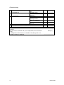
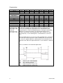
Table 2: Parameter settings
Function
Time and date
Hours / minutes
Day / month
Year
Start of summer time
End of summer time
Operating unit
This parameter is only visible on the indoor device!
Language
Info
Temporary / permanent
Display contrast
Operating lock
Off / On
Programming lock
Off / On
Save basic settings for operating unit
No / Yes
This parameter is only visible on the indoor
device!
Activate basic settings for operating unit
No / Yes
Prog.
No.
Setting
1)
level
Standard value
1
2
3
5
6
E
E
E
E
E
00h00 (h, min)
01.01 (day.month)
2004 (year)
25.03 (day.month)
25.10 (day.month)
20
22
E
F
German
Temporary
25
26
E
F
Off
27
F
Off
30
F
No
31
F
No
40
I
Indoor device 1
For use as
Indoor device 1 / Indoor device 2 / Indoor device
P / Operating device / Service device
This parameter is only visible on the indoor device!
41
369622 09.09
Programming
Function
Prog.
No.
42
Setting
1)
level
I
Operation of heating circuit 2
Jointly with heating circuit 1 / Independently
44
I
Jointly
with
heating circuit 1
Operation of heating circuit P
Jointly with heating circuit 1 / Independently
46
I
Jointly
with
heating circuit 1
Effect of presence button
None / heating circuit 1 / heating circuit 2 / Jointly
48
I
None
54
F
0.0°C
70
F
-
500
E
Mon – Sun
501
502
503
504
505
506
516
E
E
E
E
E
E
E
06h00 (h/min)
22h00 (h/min)
24h00 (h/min)
24h00 (h/min)
24h00 (h/min)
24h00 (h/min)
No
520
E
Mon – Sun
521
522
523
524
525
526
536
E
E
E
E
E
E
E
06h00 (h/min)
22h00 (h/min)
24h00 (h/min)
24h00 (h/min)
24h00 (h/min)
24h00 (h/min)
No
540
E
Mon – Sun
541
542
543
544
E
E
E
E
06h00 (h/min)
22h00 (h/min)
24h00 (h/min)
24h00 (h/min)
Allocation of indoor device 1
Heating circuit 1 / heating circuits 1 and 2
This parameter is only visible on the indoor
pump, as the boiler control unit is permanently
programmed!
This parameter is only visible on the indoor pump
Standard value
Heating circuit 1
Adjustment of room sensor
This parameter is only visible on the indoor pump
Pump version
Timer program for heating circuit 1
Presetting Mon – Sun
Mon-Sun / Mon-Fri / Sat-Sun / Mon / Tue / Wed /
Thu / Fri / Sat / Sun
st
1 phase on
st
1 phase off
nd
2 phase on
nd
2 phase off
rd
3 phase on
rd
3 phase off
Standard values
No / Yes
Timer program for heating circuit 2
Parameter only visible when heating circuit 2 exists!
Presetting Mon – Sun
Mon-Sun / Mon-Fri / Sat-Sun / Mon / Tue / Wed /
Thu / Fri / Sat / Sun
st
1 phase on
st
1 phase off
nd
2 phase on
nd
2 phase off
rd
3 phase on
rd
3 phase off
Standard values
No / Yes
Timer program 3 / heating circuit P
Presetting Mon – Sun
Mon-Sun / Mon-Fri / Sat-Sun / Mon / Tue / Wed /
Thu / Fri / Sat / Sun
st
1 phase on
st
1 phase off
nd
2 phase on
nd
2 phase off
42
369622 09.09
Programming
Function
rd
3 phase on
rd
3 phase off
Standard values
No / Yes
Timer program 4 / Domestic Hot Water system
Presetting Mon – Sun
Mon-Sun / Mon-Fri / Sat-Sun / Mon / Tue /
Wed / Thu / Fri / Sat / Sun
st
1 phase on
st
1 phase off
nd
2 phase on
nd
2 phase off
rd
3 phase on
rd
3 phase off
Standard values
No / Yes
Timer program 5
Presetting Mon – Sun
Mon-Sun / Mon-Fri / Sat-Sun / Mon / Tue /
Wed / Thu / Fri / Sat / Sun
st
1 phase on
st
1 phase off
nd
2 phase on
nd
2 phase off
rd
3 phase on
rd
3 phase off
Standard values
No / Yes
Holiday heating circuit 1
Start
End
Operating level
Frost protection / Reduced
Holiday heating circuit 2
Prog.
No.
545
546
556
Setting
1)
level
E
E
E
24h00 (h/min)
24h00 (h/min)
No
560
E
Mon – Sun
561
562
563
564
565
566
576
E
E
E
E
E
E
E
00h00 (h/min)
05h00 (h/min)
24h00 (h/min)
24h00 (h/min)
24h00 (h/min)
24h00 (h/min)
No
600
E
Mon – Sun
601
602
603
604
605
606
616
E
E
E
E
E
E
E
06h00 (h/min)
22h00 (h/min)
24h00 (h/min)
24h00 (h/min)
24h00 (h/min)
24h00 (h/min)
No
642
643
648
E
E
E
--.-- (day.month)
--.—(day.month)
Frost protection
E
E
E
--.-- (day.month)
--.—(day.month)
Frost protection
E
E
E
--.-- (day.month)
--.-- (day.month)
Frost protection
Parameter only visible when heating circuit 2 exists!
Start
652
End
653
Operating level
658
Frost protection / Reduced
Holiday heating circuit P
Parameter only visible when heating circuit P exists!
Start
662
End
663
Operating level
668
Frost protection / Reduced
43
Standard value
369622 09.09
Programming
Function
Heating circuit 1
Comfort target value
Reduced target value
Frost protection target value
Reference line for gradient
Reference line for shift
Reference line for adaptation
Off / On
Summer / winter heating limit
Daily heating limit
Minimum feed target value
Maximum feed target value
Room influence
Indoor temperature limit
Rapid heat increase
Rapid heat reduction
Off / To target value for reduction / to target
value for frost protection
Maximum optimisation for switch-on
Maximum optimisation for switch-off
Start of reduced rise
End of reduced rise
Overheating protection for pump circuit
Off / On
Mixer excess
Drive type
2-point / 3-point
Switch difference 2-point
Drive operating time
Screed function
Off / functional heating / screed heating /
functional and screed heating / manual
Screed target value manual
Screed daily value current
Screed daily value reached
Reduction to prevent overheating
Off / heating operation / permanent
With buffer storage
No / Yes
With pre-controls / feeder pump
No / Yes
Operating mode switch
None/safety operation/ reduced/
comfort/automatic
Prog.
No.
Setting
1)
level
Standard value
710
712
714
720
721
726
E
E
E
E
F
F
21.0°C
19.0°C
10.0°C
0.8
0.0
Off
730
732
740
741
750
760
770
780
E
F
F
F
I
F
F
F
18.0°C
-3°C
8°C
55°C
20%
1°C
---°C
Up
to
reduced
target value
790
791
800
801
820
F
F
F
F
F
0 min
0 min
---°C
-15°C
Off
830
832
F
F
2°C
3-point
833
834
850
F
F
F
2°C
120 s
Off
851
856
857
861
F
F
F
F
25°C
0
0
Off
870
F
Yes
872
F
Yes
900
F
Safety operation
Heating circuit 2
Parameter only visible when heating circuit 2 exists!
44
369622 09.09
Programming
Function
Comfort target value
Reduced target value
Frost protection target value
Reference line for gradient
Reference line for shift
Reference line for adaptation
Off / On
Summer / winter heating limit
Daily heating limit
Minimum feed target value
Maximum feed target value
Room influence
Indoor temperature limit
Rapid heat increase
Rapid heat reduction
Off / To target value for reduction / to target
value for frost protection
Maximum optimisation for switch-on
Maximum optimisation for switch-off
Start of reduced rise
End of reduced rise
Overheating protection for pump circuit
Off / On
Mixer elevation
Drive type
2-point / 3-point
Switch difference 2-point
Drive operating time
Screed function
Off / functional heating / screed heating /
functional
and screed heating / manual
Screed target value manual
Screed daily value current
Screed daily value reached
Reduction to prevent overheating
Off / heating operation / permanent
With buffer storage
No / Yes
With pre-controls / feeder pump
No / Yes
Operating mode switch
None/safety
operation/reduced/comfort/automatic
Heating circuit P
Prog.
No.
1010
1012
1014
1020
1021
1026
Setting
1)
level
E
E
E
E
F
F
Standard value
1030
1032
1040
1041
1050
1060
1070
1080
E
F
F
F
I
F
F
F
18.0°C
-3°C
8°C
55°C
20%
1°C
---°C
Up
to
reduced
target value
1090
1091
1100
1101
1120
F
F
F
F
F
0 min
0 min
---°C
-15°C
Off
1130
1132
F
F
2°C
3-point
1133
1134
1150
F
F
F
2°C
120 s
Off
1151
1156
1157
1161
F
F
F
F
25°C
0
0
Always
1170
F
Yes
1172
F
Yes
1200
F
Safety operation
21.0°C
19.0°C
10.0°C
0.8
0.0
Off
Parameter only visible when heating circuit P exists!
45
369622 09.09
Programming
Function
Operating mode
Safety mode / automatic / reduced / comfort
Comfort target value
Reduced target value
Frost protection target value
Reference line for gradient
Reference line for shift
Reference line for adaptation
Off / On
Summer / winter heating limit
Daily heating limit
Minimum feed target value
Maximum feed target value
Room influence
Indoor temperature limit
Rapid heat increase
Rapid heat reduction
Off / To target value for reduction / to target
value for frost protection
Maximum optimisation for switch-on
Maximum optimisation for switch-off
Start of reduced rise
End of reduced rise
Overheating protection for pump circuit
Off / On
Screed function
Off / functional heating / screed heating /
functional
and screed heating / manual
Screed target value manual
Screed daily value current
Screed daily value reached
Reduction to prevent overheating
Off / heating operation / permanent
With buffer storage
No / Yes
With pre-controls / feeder pump
No / Yes
Operating mode switch
None/safety
operation/reduced/comfort/automatic
Domestic Hot Water
Nominal target value
Reduced target value
Release
24h / day / timer programs for heating
circuits / timer program 4 / Domestic Hot Water
system / low-tariff / timer program 4 / Domestic Hot
Water system or low-tariff
46
Prog.
No.
1300
Setting
1)
level
E
Standard value
Automatic
1310
1312
1314
1320
1321
1326
E
E
E
E
F
F
21.0°C
19.0°C
10.0°C
0.8
0.0
Off
1330
1332
1340
1341
1350
1360
1370
1380
E
F
F
F
I
F
F
F
18.0°C
-3°C
8°C
55°C
20%
1°C
---°C
To reduced target
value
1390
1391
1400
1401
1420
F
F
F
F
F
0 min
0 min
---°C
-15°C
Off
1450
F
Off
1451
1455
1456
1457
1461
F
F
F
F
F
25°C
0°C
0
0
Always
1470
F
Yes
1472
F
Yes
1500
F
Safety operation
1610
1612
1620
E
F
I
55°C
44°C
Timer program 4 /
domestic hot water
circuit
369622 09.09
Programming
Function
Charging process
Absolute/Sliding/None/MK
sliding,
PK
absolute
Legionnella function
Off / periodic / weekday fixer
Legionella effect periodic
Legionella effect weekday
Mon/Tue/Wed/Thu/Fri/Sat/Sun
Legionella function time
Legionella function target value
Legionella function period
Legionella effect circulation pump
Off / On
Circulation pump release
Timer program 3/heating circuit P/Domestic
Hot Water release/timer program 4/Domestic Hot
Water system
Circulation pump fixed-cycle operation
Off/on
Circulation target value
Hx pump
H1 Domestic Hot Water system charging priority
No / yes
H1 overheating reduction
Off / on
H1 with buffer storage tank
No / yes
H1 precontrol / feeder pump
No / yes
H1 cooling requirement
No / yes
H2 Domestic Hot Water system charging priority
No / yes
H2 overheating reduction
Off / on
H2 with buffer storage tank
No / yes
H2 precontrol / feeder pump
No / yes
H2 cooling requirement
No / yes
H3 Domestic Hot Water system charging priority
No / yes
H3 overheating reduction
Off / on
H3 with buffer storage tank
No / yes
H3 precontrol / feeder pump
No / yes
47
Prog.
No.
1630
Setting
1)
level
I
Standard value
Absolute
1640
F
Off
1641
1642
F
F
3
Monday
1644
1645
1646
1647
F
F
F
F
--h—
60°C
60
On
1660
I
1661
F
Timer program 3 /
heating
circuit
pump
1663
F
2008
F
Yes
2010
F
On
2012
F
Yes
2014
F
Yes
2015
F
Yes
2033
F
Yes
2035
F
On
2037
F
Yes
2039
F
Yes
2040
F
Yes
2044
F
Yes
2046
F
On
2048
F
Yes
2050
F
Yes
On
45°C
369622 09.09
Programming
Function
H3 cooling requirement
No / yes
Swimming pool
Target value for solar heating
Target value for generator heating
Solar charging priority
No / yes
With solar incorporation
No / yes
Preliminary control unit / feeder pump
Precontrol / feeder pump
In front of buffer tank / after buffer tank
Heat pump
Condensation pump controls
Temp. requirem. / parallel compressor
operation
Lead time for condensation pump
Trailing time for condensation pump
Lead time for source
Trailing time for source
Switch difference in reflux temperature
Use of electrical lead time function
Replacement / Addition to heat pump
operation
Cut-off time for electrical lead time
Release integral for electrical lead time
Reset integral for electrical lead time
Release of electrical lead time under TA
Compensation for heat deficit
Off / on / only for screed function Number of
Domestic Hot Water system charging
attempts
Release above TA
For forced buffer charging
Locked / released
Charging of buffer store
Off / on
Defrost release below TA
Switch difference for defrosting
Evaporator temperature for end of defrosting
process
Forced defrosting interval
Maximum defrosting period
Evaporator drainage period
Evaporator cooling period
During compressor operation
Passive cooling off / passive cooling on
Maximum fan speed / Q-pump
48
Prog.
No.
2051
Setting
1)
level
F
Standard value
2055
2056
2065
E
E
F
26°C
22°C
No
2080
F
Yes
2150
I
After buffer store
2801
I
2802
2803
2819
2820
2840
2880
I
I
I
I
I
I
2881
2882
2883
2884
2886
I
I
I
I
F
Parallel compressor
operation
10 s
30 s
15 s
45 s
4°C
Addition to heat
pump operation
30 min
250°C/min
10
+ 5°C
On
2893
2910
2911
F
F
F
3
--Released
2912
F
On
2951
2952
2954
2963
2964
2965
2966
3006
F
F
F
I
I
F
F
F
10°C
2.5°C
15°C
180 min
15 min
0 min
5s
Passive cooling off
3010
F
See technical data
in
installation
manual
Yes
369622 09.09
Programming
Function
Cascade
Release integral for generator sequence
Reset integral for generator sequence
Turn-on delay
Automatic change in generator sequence
Automatic exclusion of generator sequence
None / first / last / first and last
Additional generator
Release when below outdoor temperature
Release when above outdoor temperature
Trailing time
Switch integral
Switch difference off
Locking time
Solar
Temperature difference ON
Temperature difference OFF
Min. charging temp. for Domestic Hot Water tank
Min. charging temp. for buffer
Min. charging temp. for swimming pool
Charging priority for storage tank
None / Domestic Hot Water tank / buffer
store
Relative priority of charging time
Relative priority of waiting time
Parallel operation of waiting time
Delay in secondary pump
Collector start function
Minimum operating period for collector pump
Collector start for gradient
Collector start for frost protection
Collector overheating protection
Evaporation from heating body
Minimum pump speed
Maximum pump speed
Anti-freeze
None / ethylene glycol / propylene glycol /
ethylene and propylene glycol
Anti-freeze concentration
Pump flow
Buffer storage tank
Forced charging for heating – minimum
Forced charging for heating – maximum
Forced charging time
Forced charging period – maximum
49
Prog.
No.
Setting
1)
level
Standard value
3530
3531
3533
3540
3541
F
F
F
F
F
100°C min
20°C min
5 min
500 h
None
3700
3701
3705
3720
3722
3723
F
F
F
F
F
F
----10 min
50°C / min
15°C
30 min
3810
3811
3812
3815
3818
3822
F
F
F
F
F
F
3825
3826
3827
3828
3830
3831
3834
3840
3850
3860
3870
3871
3880
F
F
F
F
F
F
F
F
F
F
F
F
F
8°C
4°C
30°C
30°C
---°C
Domestic Hot Water
tank
3881
3884
F
F
4709
4710
4711
4712
I
F
I
I
--- min
5 min
--- min
60 s
10 min
20 s
--- min/°C
--- °C
80°C
110
40%
100%
Propylene glycol
50%
200 l/h
40°C
50°C
... (h/min)
4h
369622 09.09
Programming
Function
Automatic generator lock
None / with B4 / with B4 and B42/B41
Automatic generator lock SD
Temperature difference between buffer and heating
circuit
Coating protection
Off / permanent
Maximum charging temperature
Recooling temperature
Recooling of Domestic Hot Water / heating circuits
Off / on
Recooling of collector
Off / summer / permanent
Charging sensor for electrical insert
With B4 / with B42/B41
Forced charging – electrical
No / yes
With solar integration
No / yes
Domestic Hot Water tank
Parameters depend on hydraulic system!
Charging
Once a day / several times a day
Increase in feeder target value
Transfer excess
Charging type
With B3/with B3 & B31/with B3, legio B3 &
B31
Maximum charging temperature
Recooling temperature
Recooling of generator / heating circuits
Off / on
Recooling of collector
Off / summer / permanent
Electrical insert for operating mode
Replacement / summer / permanent /
cooling
Electrical insert release
24 h a day / Domestic Hot Water release /
timer program 4 / Domestic Hot Water
system
Overheating reduction
Off / on
With buffer store
No / yes
With precontrol / feeder pump
No / yes
With solar integration
No / yes
Transfer strategy
Always / Domestic Hot Water release
50
Prog.
No.
4720
Setting
1)
level
F
Standard value
With B4
4721
4722
4739
F
F
F
5°C
-3°C
Off
4750
4755
4756
F
F
F
80°C
60°C
Off
4757
F
Off
4760
F
With B4
4761
F
No
4783
F
Yes
5010
F
Several times a day
5020
5021
5022
F
F
I
0°C
4°C
With B3
5050
5055
5056
F
F
F
70°C
80°C
Off
5057
F
Off
5060
F
Replacement
5061
F
Domestic Hot Water
release
5085
F
5090
F
5092
F
5093
F
5130
F
On
No
Yes
Yes
Always
369622 09.09
Programming
Function
Comparative temperature switch-over
Domestic Hot Water sensor B3 / Domestic Hot
Water sensor B31
Configuration
Presetting
Heating circuit 1
Off / on
Use of mixer 1
None / heating / cooling / heating and cooling
Heating circuit 2
Off / on
Domestic Hot Water actuator Q3
None / feeder pump / by-pass valve
Domestic Hot Water separator switch
Off / on
Heat source
Salt solution / water / air
Heating circuit range at TA -10°C
Solar actuator
Feeder pump / by-pass valve
External solar exchanger
Jointly / Domestic Hot Water tank / buffer tank
Combination tank
No / yes
Relay output QX1
None / process reversal valve Y22 / hot gas temperature
K31 / electrical insert 1 feed K25 / Electrical insert 2
feed K26 / By-pass valve for cooling source Y28 / feeder
pump Q14 / Cascade pump Q25 / Generator lock valve
Y4 / Electrical insert for Domestic Hot Water system K6 /
circulation pump Q4 / Collector pump Q5 / Solar pump
ext. exchanger K9 / Solar actuator buffer K8 / Solar
actuator swimming pool K18 / Electrical insert buffer
K16 / H1 pump Q15 / H2 pump Q18 / H3 pump Q19 /
heating circuit pump P Q20 / By-pass valve for cooling
Y21 / Air dehumidifier K29 / Heat requirement K27 /
Cooling requirement K28 / Alarm output K10 / Timer
program 5 K13 / Heating circuit pump 1 Q2 / Domestic
Hot water actuator Q3 / Source pump Q8/fan K19 /
Condenser pump Q9 / Compressor step 1 K1 /
Additional generator control K32
Relay output QX5
Parameter, see relay output QX1 (Prog. No.
5890)!
Relay output QX6
Parameter, see relay output QX1 (Prog. No.
5890)!
Function of input H1
BA switch-over for heating circuits and Domestic Hot
Water
system / BA switch-over for heating circuits / BAswitch-over for heating circuit 1 / BA switch-over for
heating circuit 2 / BA switch-over for heating circuit P /
Error or alarm message / Minimum feed target value /
Heat requirement 10 V / Dew point monitor / Feed
target value increase hygro / Cooling requirement /
Cooling requirement 10V / Pressure measurement 10V /
Relative humidity 10V / Indoor temperature 10V /
Release for swimming pool / Switch-on command for
heat pump Step 1
Effect of contact H1
Open-circuit contact / closed-circuit contact
51
Prog.
No.
5131
Setting
1)
level
F
Standard value
5700
5710
I
I
--On
5712
I
Heating and cooling
5715
I
Off
5731
I
Bypass valve
5736
I
Off
5800
I
Air
5810
5840
I
I
8°C
Bypass valve
5841
I
Jointly
5870
I
No
5890
I
None
5895
I
None
5896
I
None
5950
I
BA switch for heating
circuits and domestic
hot water system
5951
I
Closed-circuit contact
Domestic Hot Water
sensor B3
369622 09.09
Programming
Function
Function value for contact H1
Voltage value 1 H1
Function value 1 H1
Voltage value 2 H1
Function value 2 H1
Function input H3
Parameter, see function input H1 (Prog. No. 5950)!
Effect of contact H3
Open-circuit contact / closed-circuit contact
Function value of contact H3
Voltage value 1 H3
Function value 1 H3
Voltage value 2 H3
Effect of input EX1
Open-circuit contact / closed-circuit contact
Effect of input EX2
Open-circuit contact / closed-circuit contact
Function of input EX3
None / EW lock E6 / low tariff E5 / overload
source E14 / pressure monitor source E26 /
flow monitor source E15 / flow monitor
consumer E24 / defrosting manual E17 /
collective fault heat pump E20 / fault smooth
starter E25 / low-pressure monitor E9 / highpressure monitor E10 / overload of
compressor 1 E11 / error or alarm message
Effect of input EX3
Open-circuit contact / closed-circuit contact
Effect of input EX4
Open-circuit contact / closed-circuit contact
Function of expansion module 1
No / multifunctional / cooling circuit 1 /
heating circuit 2 / solar pump for Domestic
Hot Water / heating
circuit 1 / heating
circuit / cooling circuit 1
Function of extension module 2
Parameter, see extension module 1 (Prog.
No. 6020)!
Relay output QX21
Parameter, see relay output QX1 (Prog. No.
5890)!
Relay output QX22
Parameter, see relay output QX1 (Prog. No.
5890)!
Prog.
No.
5952
5953
5954
5955
5956
5960
Setting
1)
level
I
I
I
I
I
I
5961
I
5962
5963
5964
5965
5966
5981
I
I
I
I
I
F
5983
F
5984
I
Standard value
55°C
0
0
10
100
BA
switch-over
heat.
circ./drink.
water
Closed-circuit
contact
30°C
0
0
10
100
Open-circuit contact
Closed-circuit
contact
None
5985
F
5987
F
6020
I
6021
I
6030
I
6031
I
6032
I
Open-circuit contact
Open-circuit contact
None
None
None
None
None
Relay output QX23
Parameter, see relay output QX1 (Prog. No.
5890)!
52
369622 09.09
Programming
Function
Sensor input BX21
None / buffer tank sensor B4 / buffer tank
sensor B41 / collector sensor B6 / Domestic
Hot Water sensor
B31 / cooling agent
sensor liquid B83 / domestic hot water
circulation sensor B39 / swimming pool
sensor B13 / solar feed sensor B63 / solar
reflux sensor B64 / buffer tank sensor B42
/ section feed sensor B10 / cascade reflux
sensor B70 / special
temperature sensor
1 / special temperature sensor 2
/
Domestic Hot Water sensor B3 / hot gas
sensor B81
Sensor input BX22
Parameter, see sensor input BX21 (Prog.
No. 6040)!
Prog.
No.
6040
Setting
1)
level
I
Standard value
None
6041
I
None
6046
I
BA
switch
for
heating circuits +
Domestic Hot Water
system
6047
I
6048
6049
6050
6051
6052
6071
I
I
I
I
I
I
6072
I
6075
6097
I
F
6098
6100
6110
6120
F
F
F
F
6200
I
0°C
0.0°C
20 h
On
6201
I
No
6212
6213
6215
6217
6220
I
I
I
I
F
No
Input function H2
BA switch-over heating circuits + Domestic Hot
Water system / BA switch-over heating circuit 1 /
BA switch-over heating circuit 2 / BA switch-over
heating circuit P / error or alarm message /
minimum feed target value / heat requirement
10V / dew point monitor / feed target value
increase hygro / cooling requirement / cooling
requirement 10V / pressure measurement 10V /
relative indoor humidity 10V / indoor temperature
10V / release for swimming pool / switch-on
command for heat pump step 1
Effect contact H2
Open-circuit contact / closed-circuit contact
Minimum feed target value H2
Voltage value 1 H2
Function value 1 H2
Voltage value 2 H2
Function value 2 H2
Signal logic output UX
Standard / inverted
Signal output UX
0...10V / PWM
Temperature value 10V UX
Sensor type of collector
NTC / PT1000
Adjustment of collector sensor
Adjustment of outdoor sensor
Time constant for building
System frost protection
Off / on
Save sensor
No / yes
Delete sensor
No / yes
Control number of generator 1
Control number of generator 2
Control number of tank
Control number of heating circuits
Software version
LPB system
53
Closed-circuit
contact
55°C
0
0
10
100
Standard
0...10V
100°C
NTC
-
369622 09.09
Programming
Function
Device address
Segment address
Bus feed function
Off / automatic
Bus feed status
Off / on
Summer switch-over
Local / central
Operating mode switch-over
Local / central
Domestic Hot Water allocation
Local heating circuits / all heating circuits in
segment / all heating circuits in system
TA limit for external generator taken into account
No / yes
Clock operation
Autonomous / slave without remote setting /
slave with remote setting / master
Outdoor temperature - supplier
Errors
Reset alarm relay
No / yes
Reset heat pump
No / yes
Feed temperature 1 alarm
Feed temperature 2 alarm
Domestic Hot Water charge alarm
Feed temperature cooling 1 alarm
Time stamp for error history 1
Error code for error history 1
Time stamp for error history 2
Error code for error history 2
Time stamp for error history 3
Error code for error history 3
Time stamp for error history 4
Error code for error history 4
Time stamp for error history 5
Error code for error history 5
Time stamp for error history 6
Error code for error history 6
Time stamp for error history 7
Error code for error history 7
Time stamp for error history 8
Error code for error history 8
Time stamp for error history 9
54
Prog.
No.
6600
6601
6604
Setting
1)
level
I
F
F
1
0
Automatic
6605
F
On
6621
F
Local
6623
F
Central
6625
F
All heating circuits
in system
6632
F
Yes
6640
I
Autonomous
6650
F
0
6710
I
No
6711
I
No
6740
6741
6745
6746
6800
F
F
F
F
F
F
F
F
F
F
F
F
F
F
F
F
F
F
F
F
F
--- min
--- min
--- min
--- min
6802
6804
6806
6808
6810
6812
6814
6816
Standard value
369622 09.09
Programming
Function
Error code for error history 9
Time stamp for error history 10
Error code for error history 10
Errors
Reset alarm relay
No / yes
Reset heat pump
No / yes
Feed temperature 1 alarm
Feed temperature 2 alarm
Domestic Hot Water charge alarm
Feed temperature cooling 1 alarm
Time stamp for error history 1
Error code for error history 1
Time stamp for error history 2
Error code for error history 2
Time stamp for error history 3
Error code for error history 3
Time stamp for error history 4
Error code for error history 4
Time stamp for error history 5
Error code for error history 5
Time stamp for error history 6
Error code for error history 6
Time stamp for error history 7
Error code for error history 7
Time stamp for error history 8
Error code for error history 8
Time stamp for error history 9
Error code for error history 9
Time stamp for error history 10
Error code for error history 10
Maintenance / service
Heat pump time interval
Heat pump time since service
Max Starts Comp1 / operating hour
Actual Starts Comp1 / operating hour
Range Condens Max / week
Actual Range Condens Max / week
Range Condens Min / week
Actual Range Condens Min / week
Range Evaporator Max / week
55
Prog.
No.
Setting
1)
level
F
F
F
Standard value
6710
I
No
6711
I
No
6740
6741
6745
6746
6800
F
F
F
F
F
F
F
F
F
F
F
F
F
F
F
F
F
F
F
F
F
F
F
F
--- min
--- min
--- min
--- min
I
I
I
I
I
I
I
I
I
--0 months
4
0
25
0
10
0
10
6818
6802
6804
6806
6808
6810
6812
6814
6816
6818
7070
7071
7072
7073
7076
7077
7078
7079
7080
369622 09.09
Programming
Function
Act Range Evaporator Max / Week
Range Evaporator Min / Week
Act Range Evaporator Min / Week
Domestic Hot Water Tank Time Interval
Domestic Hot Water Tank Since Service
Domestic Hot Water Tank Feed Temp Heat Pump
Minimum
Act Domestic Hot Water Feed Temperature Heat
Pump
Eco-function
Locked / released
Eco operation
Off / on
Emergency operation
Off / on
Emergency operation for function start
Manual / Automatic
Simulation of outdoor temperature
Trigger defrost
No / yes
Input/output test
Relay test
No test / everything off / relay output QX23
Module 1 / relay output QX21 Module 1 /
relay output QX22 Module 1 / relay output
QX1 / relay output QX2 / relay output ZX3 /
relay output QX4 / relay output QX5 / relay
output QX6 / relay output QX23 Module 2 /
relay output QX21 Module 2 / relay output
QX22 Module 2 / relay output QX7 / relay
output QX8
Output test UX
Voltage signal UX
PWM signal P1
Outdoor temperature B9
Source of input temperature B91
Sensor temperature B92, B84
Sensor temperature BX1
Sensor temperature BX4
Sensor temperature BX5
Sensor temperature BX21 Module 1
Sensor temperature BX22 Module 1
Sensor temperature BX21 Module 2
Sensor temperature BX22 Module 2
Voltage signal H1
Contact state H1
Open / closed
Voltage signal H2
Contact state H2
Open / close
56
Prog.
No.
7081
7082
7083
7090
7091
7092
7093
7119
Setting
1)
level
I
I
I
I
I
I
I
F
0
10
0
-- months
0 months
45°C
20°C
Locked
7120
E
Off
7141
E
Off
7142
F
Manual
7150
7152
I
E
---°C
No
7700
I
No test
7710
7711
7714
7730
7775
7777
7820
7823
7824
7830
7831
7832
7833
7840
7841
I
I
7845
7846
I
I
I
I
I
I
I
I
I
I
I
I
I
I
Standard value
-
Open
369622 09.09
Programming
Function
Voltage signal H3
Contact state H3
Open / closed
Input EX1
0 V / 230 V
Input EX2
0 V / 230 V
Input EX3
0 V / 230 V
Input EX4
0 V / 230 V
Input EX5
0 V / 230 V
Input EX6
0 V / 230 V
Input EX7
0 V / 230 V
Status
Status of heating circuit 1
Status of heating circuit 2
Status of heating circuit P
Status of Domestic Hot Water
Status of cooling circuit 1
Status of heat pump
Status of solar pump
Status of buffer tank
Status of swimming pool
Status of additional generator
Time stamp for status history 1
Status code for status history 1
Time stamp for status history 2
Status code for status history 2
Time stamp for status history 3
Status code for status history 3
Time stamp for status history 4
Status code for status history 4
Time stamp for status history 5
Status code for status history 5
Time stamp for status history 6
Status code for status history 6
Time stamp for status history 7
Status code for status history 7
Time stamp for status history 8
Status code for status history 8
57
Prog.
No.
7854
7855
Setting
1)
level
I
I
Standard value
Open
7911
I
0V
7912
I
0V
7913
I
0V
7914
I
0V
7915
I
0V
7916
I
0V
7917
I
0V
8000
8001
8002
8003
8004
8006
8007
8010
8011
8022
8050
8051
8052
8053
8054
8055
8056
8057
8058
8059
8060
8061
8062
8063
8064
8065
I
I
I
I
I
I
I
I
I
I
I
I
I
I
I
I
I
I
I
I
I
I
I
I
I
I
-
369622 09.09
Programming
Function
Time stamp for status history 9
Status code for status history 10
Time stamp for status history 10
Status code for status history 10
Cascade diagnosis
Priority / status of generator 1
Missing / faulty / manual operation active /
Generator
lock
active
/chimney-sweep
function active/Domestic Hot Water system
separation switch active / outdoor temperature
limit active / not released / released
Priority / status of generator 2
Parameter, see priority/status
(Prog.No.8100)
Priority / status of generator 3
Parameter, see priority/status
(Prog.No.8100)
Priority / status of generator 4
Parameter, see priority/status
(Prog.No.8100)
Priority / status of generator 5
Parameter, see priority/status
(Prog.No.8100)
Priority / status of generator 6
Parameter, see priority/status
(Prog.No.8100)
Priority / status of generator 7
Parameter, see priority/status
(Prog.No.8100)
Priority / status of generator 8
Parameter, see priority/status
(Prog.No.8100)
Priority / status of generator 9
Parameter, see priority/status
(Prog.No.8100)
Priority / status of generator 10
Parameter, see priority/status
(Prog.No.8100)
Priority / status of generator 11
Parameter, see priority/status
(Prog.No.8100)
Priority / status of generator 12
Parameter, see priority/status
(Prog.No.8100)
Priority / status of generator 13
Parameter, see priority/status
(Prog.No.8100)
Priority / status of generator 14
Parameter, see priority/status
(Prog.No.8100)
Priority / status of generator 15
Parameter, see priority/status
(Prog.No.8100)
Priority / status of generator 16
Parameter, see priority/status
(Prog.No.8100)
Cascade feed temperature
Cascade feed target value
58
gener. 1
gener.
1
gener.
1
gener.
1
gener. 1
gener.
1
gener. 1
gener. 1
gener. 1
gener. 1
gener. 1
gener.
1
gener. 1
gener. 1
gener. 1
Prog.
No.
8066
8067
8068
8069
Setting
1)
level
I
I
I
I
8100
I
8102
I
8104
8106
8108
8110
8112
8114
8116
8118
8120
8122
Standard value
-
I
I
I
I
I
I
I
I
I
I
I
I
I
I
I
I
8124
8126
8128
8130
8138
8138
369622 09.09
Programming
Function
Cascade reflux temperature
Cascade reflux target value
Current generator sequence switch
Generator diagnosis
Compressor 1 K1
Off / on
Electrical insert 1 – feeder
Off / on
Electrical insert 2 – feeder
Off / on
Source buffer Q8 / fan K19
Off / on
Speed of source pump
Condenser pump Q9
Off / on
Reflux temperature for heat pump
Target value for heat pump
Feed temperature for heat pump
Hot gas temperature 1
Hot gas temperature max
Cooling agent temperature – liquid
Temperature range for condenser
Temperature range for evaporator
Source input temperature
Source input min
Source output temperature
Source output min
Remaining down-time for Step 1 – min
Remaining operating time for Step 1 – min
Remaining time for source restriction temp – min
Operating hours of compressor 1
Start counter for compressor 1
Locking period for heat pump
Counter for number of heat pump locks
Operating hours for electrical feeder
Start counter for electrical feeder
Fan speed
Fan K19
Off / on
Process reversal valve
Off / on
Evaporator temperature
Temperature difference defrosting – actual value
Temperature difference defrosting – target value
59
Prog.
No.
8140
8141
8150
Setting
1)
level
I
I
I
Standard value
8400
E
-
8402
E
-
8403
E
-
8404
E
-
8405
8406
F
I
-
8410
8411
8412
8415
8416
8420
8425
8426
8427
8428
8429
8430
8440
8442
8444
8450
8451
8454
8455
8456
8457
8469
8470
E
E
E
I
F
I
I
I
E
I
E
I
I
I
I
E
E
F
F
F
F
F
I
8471
I
8475
8477
8478
I
I
I
- °C
- °C
- °C
- °C
- °C
- °C
- °C
- °C
- °C
- °C
- °C
- °C
--- min
--- min
--- min
0h
0
0h
0
0h
0
369622 09.09
Programming
Function
Remaining time for defrost locking
Remaining time for forced defrosting
Number of defrosting attempts
Defrosting status
heat pump off, TA defrosting release off/
locked/ monitor ice /preheat for defrosting/
defrosting
active/drain/cool
down
evaporator/fault/forced defrosting/defrosting
stabilisation/defrosting with fan/ defrosting
with compressor /forced defrosting of fan
/forced defrosting of compressor
Speed of collector pump 1
Speed of solar pump ext. defrost
Speed of solar pump buffer
Speed of solar pump swimming pool
Collector temperature 1
Collector temperature 1 max
Collector temperature 1 min
dT collector 1 / Domestic Hot Water system
dT collector 1 / buffer
dT collector 1 / swimming pool
Solar feed temperature
Solar reflux temperature
Daily output of solar energy
Total output of solar energy
Operating hours to achieve solar output
Operating hours to achieve collector overheating
Consumer diagnosis
Outdoor temperature
Outdoor temperature minimum
Outdoor temperature maximum
Outdoor temperature with absorption
Outdoor temperature mixed
Relative humidity indoors
Indoor temperature
Dew point temperature
Heating circuit pump Q2
Off / on
Heating circuit mixer open Y1
Off / on
Heating circuit mixer closed Y2
Off / on
Room temperature 1
Room target value 1
Feed temperature 1
60
Prog.
No.
8480
8481
8485
8487
Setting
1)
level
I
I
I
I
Standard value
8505
8506
8507
8508
8510
8511
8512
8513
8514
8515
8519
8520
8526
8527
8530
8531
F
F
F
F
F
I
I
I
I
I
I
I
E
E
E
F
8700
8701
8702
8703
8704
8720
8721
8722
8730
E
I
I
I
I
I
I
I
I
- °C
- °C
- °C
- °C
- °C
8731
I
-
8732
I
-
8740
8741
8743
E
E
E
- °C
- °C
- °C
WP off, TA release
off
- °C
200°C
-28°C
0°C
0°C
0°C
00h00
00h00
-
369622 09.09
Programming
Function
Lead time target value 1
Cooling circuit pump Q24
Cooling circuit mixer open Y23
Cooling circuit mixer closed Y24
By-pass valve cooling Y21
Lead time temperature cooling 1
Lead time target value cooling 1
Heating circuit pump Q6
Off / on
Heating circuit mixer open Y5
Off / on
Heating circuit mixer closed Y6
Off / on
Room temperature 2
Room target value 2
Lead time temperature 2
Lead time target value 2
Room temperature P
Room target value P
Lead time target value P
Domestic Hot Water pump Q3
Off / on
Electrical insert for Domestic Hot Water system K6
Off / on
Domestic Hot Water temperature 1
Domestic Hot Water target value
Domestic Hot Water temperature 2
Domestic Hot Water circulation temperature
Operating hours for Domestic Hot Water pump
Start counter for Domestic Hot Water pump
Operating hours for electrical unit (Domestic Hot
Water system)
Start counter for electrical unit (Domestic Hot Water
system)
Swimming pool temperature
Swimming pool target value
Section feed temperature
Section feed time target value
Section feed target value – cooling
Electrical insert for buffer
Buffer tank temperature 1
Buffer tank target value 1
Buffer tank temperature 2
Buffer tank temperature 3
Operating hours for electrical buffer
61
Prog.
No.
8744
8751
8752
8753
8754
8756
8757
8760
Setting
1)
level
E
I
I
I
I
E
E
I
- °C
- °C
- °C
-
8761
I
-
8762
I
-
8770
8771
8773
8774
8800
8801
8803
8820
E
E
E
E
E
E
E
I
- °C
- °C
- °C
- °C
- °C
- °C
- °C
-
8821
I
-
8830
E
E
E
I
F
F
F
F
I
I
I
I
I
I
E
I
E
I
F
- °C
- °C
- °C
8832
8835
8840
8841
8842
8843
8900
8901
8950
8951
8957
8970
8980
8981
8982
8983
8990
Standard value
0h
0
0h
0
- °C
- °C
- °C
- °C
0h
369622 09.09
Programming
Function
Start counter for electrical buffer
Lead time target value H1
Lead time target value H2
Lead time target value H3
Water pressure H1
Water pressure H2
Water pressure H3
Relay output QX1
Off / on
Relay output QX2
Off / on
Relay output QX3
Off / on
Relay output QX4
Off / on
Relay output QX5
Off / on
Relay output QX6
Off / on
Relay output QX7
Off / on
Relay output QX8
Off / on
Relay output QX21 Module 1
Off / on
Relay output QX22 Module 2
Off / on
Relay output QX22 Module 3
Off / on
Relay output QX21 Module 1
Off / on
Relay output QX22 Module 2
Off / on
Relay output QX23 Module 3
Off / on
Info option
Prog.
No.
8991
9000
9001
9004
9005
9006
9009
9031
Setting
1)
level
F
I
I
I
I
I
I
I
9032
I
9033
I
9034
I
9035
I
9036
I
9037
I
9038
I
9050
I
9051
I
9052
I
9053
I
9054
I
9055
I
Standard value
0
- °C
- °C
- °C
Display of the info values depends on the operating state!
Error message
Maintenance
Relay test
Current screed target value
Current screed value achieved
Room temperature
Status of heat pump
Status of solar heating
62
369622 09.09
Programming
Status of buffer tank
Status of Domestic Hot Water
Status of swimming pool
Status of heating circuit 1
Status of cooling circuit 1
Status of heating circuit 2
Status of heating circuit P
1) E = end user, I = maintenance, F = technical
expert
Parameters with the program numbers (Prog. No.) 1 to 54 are individual
parameters of the operating unit and the indoor system and can therefore be set
independently on both devices. All parameters from Prog. No. 500 on are stored in
the controller and are therefore identical. The value entered last is the valid value.
9.4 Explanations of the parameter list
Time and date
(1 + 3)
Summer time
(5-6)
Language
(20)
Information
(22)
Fault display
(23)
Operation lock
(26)
Programming lock
(27)
63
Time and date
The controller has a year clock with options to set the time, day,
month and year. Time and date must be correctly set to ensure
that heating programs work in the way they were programmed.
The start of summer time can be set with Prog. No. 5; the end of
summer time is defined with Prog. No. 6. The time is adjusted on
the Sunday after the date set.
Operating unit
The language for the menu interface can be changed with Prog.
No. 20
Temporary: info display changes after 8 minutes in basic display
state
Permanent: Info display is permanently shown after call-up with
the info button.
The number determines whether only the fault code or the fault
code with text is shown in the event of a fault.
When the lock is active, the following operating elements are
locked:
- Operating buttons for heating and Domestic Hot Water
operation
- Rotary button (comfort target value for indoor temperature)
- Presence button (only for indoor system)
When the lock is active, the parameters may be shown but not
changed
- Temporary lock:
Press the OK and ESC buttons at the same time for at least 3
seconds.
The lock is active after leaving the programming level
- Permanent lock:
First temporary lock, then set Prog. No. 27 to "Off".
369622 09.09
Programming
Save basic settings
of to operating unit
(30)
Activate basic
settings of operating
unit
(31)
Use as
(40)
Allocation Indoor
Unit 1
(42)
Operation heating
circuit 2/heating
circuit P
(44, 46)
Effect of preference
button
(48)
Correction of indoor
sensor
(54)
Device version
(70)
64
The control parameters are written to / saved in the indoor system
(only available for the indoor system)
Caution! The parameters of the indoor unit are overwritten! This
makes it possible to save the individual programming of the indoor
unit controller.
The parameters saved in the operating unit or the indoor system are
written to the controller.
Caution! The parameters in the controller are overwritten! The factory
settings are stored in the controller.
- Activate Prog. No. 31 at the operating unit:
The controller is reset to the factory settings.
- Activate Prog No. 31 at the indoor system:
The individual programming of the indoor unit is written to the
controller.
- Indoor system 1/2/P: This setting determines for which heating
circuit the indoor system, at which the setting is made, shall the
used. When Indoor Unit 1 was selected, additional heating circuits
can be allocated to the indoor system by using Prog. No. 42. When
Indoor Unit 2/P was selected, only the respective heating circuit
can be operated.
- Operating unit: This setting is intended for plain operation without
indoor functions and is not required in connection with this
controller.
- Service device: This setting is used, for example, to save or store
controller settings.
When the Indoor Unit 1 (Prog. No. 40) setting was selected, Prog. No.
42 must be used to define whether the indoor unit is allocated to
Heating Circuit 1 or to both heating circuits.
When Indoor Unit 1 or the operating unit (Prog. No. 40) was selected,
Prog. No. 44 or 46 must be used to define whether the heating
circuits heating circuit 2 and heating circuit P are to be controlled on
the operating unit jointly with Heating Circuit 1, or whether they are to
be controlled independently of Heating Circuit 1.
The effect of the presence button on the heating circuits is defined
with Prog. No. 48.
Prog. No. 54 can be used to correct the display of the temperature
value transmitted by the indoor sensor.
Display of the current device version.
Timer programs
The Timer Programs 1 and 2 are always allocated to the respective
heating circuits (1 and 2) and are only shown when these heating
circuits are present and also switched on in the configuration menu
(Prog. No. 5710 and 5715).
369622 09.09
Programming
The Timer Program 3 can be used for the Heating Circuit P, the
domestic hot water and the circulation pump, depending on the
setting. It is always displayed.
Preselection
(500, 520, 540, 560)
The Timer Program 4 can be used for domestic hot water and for the
circulation pump, depending on the setting. It is always displayed.
Selection of week days or week blocks. The week blocks (Mo-Su,
Mo-Fr and Sa-Su) are setting aids. The times set there are only
copied to the respective week days and can thereafter be changed for
these individual week days as required.
The heating program is determined by the times on the individual
week days.
Heating phases
(501 to 506, 521 to
526, 541 to 546 and
561 to 566)
Standard values
(516, 536, 556, 576)
Start of holidays
(642, 652, 662)
End of holidays
(643, 653, 663)
Operating level
(648, 658, 668)
When a time in a day group is changed, all 3 switch-on and switch-off
phases of the day group are automatically taken over.
Up to 3 heating phases can be set per heating circuit. They are active
on the days selected under Preselection (Prog. No. 500, 520, 540,
560). The system heats in all heating phases up to the comfort target
value selected. Outside the heating phases, it only heats up to the
reduced target value.
The timer programs are only active in the "Automatic" operating
mode.
Sets the standard values specified in the setting table.
Holiday programs
The holiday program can be used to set the heating circuits during a
specific holiday period to a selectable operating level.
The holiday program can be used to set the heating circuits for up to
8 holiday periods to a selectable operating level.
Enter the start of the holidays
Enter the end of the holidays
Selects the operating level (reduced target value or frost protection)
for the holiday program.
A holiday period ends on the last day at 0:00. The holiday programs
are only active in the "Automatic" operating mode.
65
369622 09.09
Programming
Operating mode
(1300)
Comfort target value
(710, 1010, 1310)
Reduced target value
(712, 1012, 1312)
Frost protection value
(714, 1014, 1314)
Maximum comfort
target value
(716, 1016, 1316)
Characteristic incline
(720, 1020, 1320)
66
Heating circuits
This Prog. No. can be used to select the operating mode for the
Pump Circuit P.
The operating mode for Heating Circuits 1 and 2 is directly set on the
operating unit.
Sets the comfort target value.
Sets the desired indoor temperature during the reduction heating
phase. When no indoor sensor is available or when the indoor effect
is switched off (Prog. No. 750), this value is used to calculate the feed
temperature that would result in the set indoor temperature. The
heating circuit remains switched off until the feed temperature has
dropped to the value that would make the indoor temperature drop
below the frost protection temperature.
Sets the maximum comfort target value.
The heating characteristic is used to determine the feed target
temperature to control the heating circuit based on the outside
temperature. The incline of the characteristic determines by how
much the feed temperature changes per degree change of the
outside temperature.
Determining the heating characteristic incline: Enter the lowest
calculated outside temperature for the climate zone (e.g. -12 °C for
Frankfurt) in the chart. Enter the maximum feed temperature of the
heating circuit at which it is theoretically still possible to achieve 20 °C
inside temperature at -12 °C outside temperature (e.g. horizontal line
at 60 °C). The intersection of both lines provides the value of the
heating characteristic incline.
Determining the heating characteristic incline
Enter the lowest calculated outside temperature for the climate zone
into the diagram (see Figure 15) (e.g. vertical line at -10 °C). Enter
the maximum feed temperature of the heating circuit (e.g. horizontal
line at 40 °C).
The intersection of both lines provides the value of the heating
characteristic incline.
369622 09.09
Programming
Feed temperature
Figure 15: Heating characteristic diagram
Outside temperature
Shift of characteristic
(721, 1021, 1321)
Adaptation of
characteristic
(726, 1026, 1326)
Summer / winter
heating limit
(730, 1030, 1330)
67
Correction of the heating characteristic by parallel shift when the
inside temperature is generally too high or too low.
Automatic adaptation of the heating characteristic to the current
situation, which obviates a correction of the heating characteristic
incline.
An indoor sensor must be connected for automatic adaptation of the
heating characteristic. The value for the indoor effect (see Prog. No.
750, 1050, 1350) must be between 1% and 99%. Possible heating
element valves in the main room (place of installation of the indoor
sensor) must be opened completely.
The heating circuit switches to summer mode as soon as the average
of the outside temperatures in the last 24 hours exceeds this value by
1 °C. The heating circuit switches back to winter mode as soon as the
average of the outside temperatures in the last 25 hours falls 1 °C
below this value.
369622 09.09
Programming
Figure 16: Summer / winter heating limit
Attenuated outside
temperature
(Prog. No. 8703)
Daily heating limit
(732, 1032, 1332)
Feed target value
limits
Minimum
(740, 1040, 1340)
Maximum
(741, 1041, 1341)
68
SWHG summer / winter heating limit
T
Temperature
t
Time
The daily heating limit function switches off the heating circuit when
the current outside temperature increases so that its difference to the
current operating level (reduced or comfort target value) is equal to
the difference set here. The heating again switches on when the
current outside temperature falls below the temperature difference set
minus 1 °C.
This function is not active in the "Permanent nominal temperature"
operating mode.
Sets an area for the feed target value. When the feed target
temperature has reached one of the limit values, it is not permitted to
exceed or fall below the respective limit value, even if the heat
demand increases or drops.
369622 09.09
Programming
Indoor effect
(750, 1050, 1350)
The feed temperature is calculated as a function of the outside
temperature using the heating curve. This control type assumes that the
heating characteristic is set correctly, because with this setting, the
controller does not make use of the indoor temperature.
When an RGT or RGB indoor device is connected and the setting for the
"Indoor effect" is between 1% and 99%, the deviation of the indoor
temperature from the target value is registered and taken into account
for the control of the temperature. External heat sources can in this way
be considered and the indoor temperature can be more steadily
maintained. The effect of the deviation can be set in percent. The better
suited the main room (room temperature not distorted, permanent place
of installation, etc.), the higher the value can be set and the more the
indoor temperature is considered.
When the main room (place of installation of the indoor sensor) contains
heating element valves, they must be completely opened.
Indoor
temperature
limitation
(760, 1060, 1360)
- Setting for weather control with indoor effect: 1% -99%
- Setting for pure weather control: ---%
- Setting for pure indoor control : 100%
The switching difference set here switches the heating circuit pump on
and off as a function of the indoor temperature. The switching-off point
for the pump is set as a difference to the set target indoor temperature.
The switching-on point is 0.25 °C below the set indoor target value. This
function is only possible with an RGT or RGB indoor device and active
"indoor effect".
An indoor sensor must be connected. This function only applies for pump
heating circuits.
Figure 17: Room temperature limitation
TRx
RTw
P
t
69
Indoor temperature actual value
Indoor temperature target value
Pump
Time
369622 09.09
Programming
Fast heating-up
(770, 1070, 1370)
The fast-heating-up function becomes active when the indoor target
value switches from protection level or reduced level to comfort level.
During fast-heating-up function, the indoor target value is increased by
the value set here. The actual indoor temperature increases to the new
threshold in a relatively short period, due to this setting. The fast-heatingup function is terminated when the indoor temperature measured by an
RGT/RGTF or RGB indoor device has increased to 0.25 °C below the
comfort target value.
Without an indoor sensor or indoor effect, fast heating-up is performed
according to an internal calculation in which the indoor target value is
used as a basis. The duration of the fast-heating-up function and the
effect on the feed temperature therefore depends on the outside
temperature.
Figure 18: Fast heating-up
Fast reduction
(780, 1080, 1380)
TRw
Indoor temperature target value
TRx
Indoor temperature current value
DTRSA Indoor temperature target value increase
The fast-reduction function becomes active when the indoor target value
switches from the comfort level to another operating level (options are
reduced level or protection level). During the fast-reduction function, the
heating circuit pump is switched off. In mixer circuits, the mixing valve is
closed as well. During the fast-reduction function, no heat request is sent
to the heat generator.
The fast-reduction function is possible with or without indoor sensor: With
indoor sensor, the function switches off the heating circuit until the indoor
temperature has dropped to the reduced target value or the frost
protection target value. The heating circulation pump is again switched
on and the mixing valve is released when the indoor temperature has
dropped to the reduced target value or the frost protection target value.
Without an indoor sensor, the fast-reduction function switches off the
heading as function of the outside temperature and the building time
constant (Prog. No. 6110) until the temperature has theoretically dropped
to the reduced target value or the frost protection target value.
Duration of the fast-lowering function when lowering by 2 °C, in hours:
Building time constant (configuration, Prog. No. 6110)
Mixed outside
temperature
0h
2h
5h
10 h
15 h
20 h
50 h
15 °C
0
3.1
7.7
15.3
23
10 °C
0
1.3
3.3
6.7
10
13.4
5 °C
0
0.9
2.1
4.3
6.4
8.6
21.5
0 °C
0
0.6
1.6
3.2
4.7
6.3
15.8
-05 °C
0
0.5
1.3
2.5
3.8
5
12.5
70
369622 09.09
Programming
-10 °C
0
0.4
1
2.1
3.1
4.1
10.3
-15 °C
0
0.4
0.9
1.8
2.6
3.5
8.8
-20 °C
0
0.3
0.8
1.5
2.3
3.1
7.7
Duration of the fast-lowering function when lowering by 4 °C, in hours:
Building time constant (configuration, Prog. No. 6110)
Mixed outside
temperature
0h
2h
5h
10 h
15 h
20 h
50 h
15 °C
0
9.7
24.1
10 °C
0
3.1
7.7
15.3
23
5 °C
0
1.9
4.7
9.3
14
18.6
0 °C
0
1.3
3.3
6.7
10
13.4
-05 °C
0
1
2.6
5.2
7.8
10.5
26.2
-10 °C
0
0.9
2.1
4.3
6.4
8.6
21.5
-15 °C
0
0.7
1.8
3.6
5.5
7.3
18.2
-20 °C
0
0.6
1.6
3.2
4.7
6.3
15.8
The switch-on and switch-off time optimisation is a timer function that is
Switch-on
optimisation max. possible with or without an indoor device. When an indoor device is
(790, 1090, 1390) present, the switching of the operating level is shifted relative to the
programmed time so that the building dynamics (heating-up and coolingSwitch-off
optimisation max. down time) is taken into account. The desired temperature level is
(791, 1091, 1391) therefore reached at the time programmed. If this is not the case (too
early or too late), a new switching time is calculated that is used next
time.
When no indoor device is present, the earlier switching time is calculated
based on the outside temperature and the building time constant (Prog.
No. 6110). The optimisation time (shift forwards) can be limited here to a
maximum value. When the optimisation time = 0, the function is switched
off.
Figure 19: Switch-on and switch-off optimisation
Xein
Xaus
ZSP
TRw
TRx
71
Switch-on time shifted forwards
Switch-off time shifted forwards
Time switching program
Indoor temperature target value
Indoor temperature actual value
369622 09.09
Programming
Reduced-increase
start
(800, 1100, 1400)
Reduced-increase
end
(801, 1101, 1401)
When little heating power is required, the reduced indoor target value
at cold outside temperatures can be increased. The increase depends
on the outside temperature. The lower the outside temperature, the
more the reduced target value for the indoor temperature is
increased. The start of the increase and the end point can be set.
Between these two points the increase of the reduced target value to
the comfort target value is linear.
Figure 20: Reduced increase
TRwA1
TRwA2
TRK
TRR
TAgem
Overheating
protection for pump
heating circuit
(820, 1120, 1420)
Drive type
(832, 1132)
Switching difference
2-point
(833, 1133)
Drive runtime
(843, 941, 1134)
72
Reduced-increase start
Reduced-increase end
Comfort target value
Indoor temperature reduced target value
Mixed outside temperature
This function prevents overheating of the pump heating cycle by
switching the pump on and off when the feed temperature is higher
than the feed temperature required according to the characteristic
(e.g. when there is increased demand by other consumers).
- 2-point: The controller controls the drive with only one relay output.
A signal at the output opens the addressed valves. When the signal
is not present, the valve automatically closes.
- 3-point: The controller controls the drive with two relay outputs. One
dedicated output is used for opening and one for closing of the
controlled valve.
The "Switching difference 2-point" for the 2-point drive might have to
be adjusted. The switching difference has no meaning for the 3-point
drive.
In mixer circuits, a kick of the mixer drive is initiated after the pump
kick (pump is off). The mixer is moved in the OPEN and then in the
CLOSED direction.
The time during which the control signal acts in the OPEN direction
corresponds to the drive runtime.
369622 09.09
Programming
Screed function
(850, 1150,
1450)
The screed function is used for controlled drying of screed screeds.
- Off: The function is switched off.
- Function heating (Fh): Part 1 of the temperature profile is automatically
executed.
- Covering-readiness heating (Bh): Part 2 of the temperature profile is
automatically executed.
- Function and covering-readiness heating: The whole temperature
profile is automatically executed.
- Manual: The screed target value is manually maintained.
Figure 21: Temperature profile for screed drying function
X
Fh
Bh
Starting day
Function heating
Covering-readiness heating
Important! The relevant regulations and standards of the screed
manufacturer must be considered.
Manual screed
target value
(851, 1151,
1451)
Current screed
target value
(1455)
Current screed
day
(856, 1156,
1456)
Fulfilled screed
day
(857, 1157,
1457)
73
Correct function is only possible with a correctly installed system
(hydraulics, electrics and settings).
Deviations may lead to damage of the screed.
The screed function can be prematurely terminated by setting 0-Off.
Sets the temperature to the value that is manually selected when the
screed function is active (see Prog. No. 850).
Current target value of the screed function.
Current day of the screed function.
Days of the screed function already passed.
369622 09.09
Programming
Over-temperature
reduction
(861, 1161, 1461)
With buffer storage
unit
(870, 1170, 1470)
With preregulator /
feed pump
(872, 1172, 1472,
5092)
Operating mode
switching
(900, 1200, 1500)
Nominal target value
(1610)
Reduced target
value
(1612)
Release
(1620)
74
Surplus heat can be reduced by generating less heat in the indoor
heating system when the over-temperature reduction is activated on
Input H1 or H3 or when the maximum temperature in the system is
exceeded.
- Off: The function is switched off
- Heating operation: The function is limited to a reduction during the
heating times
- Always: The function is generally released.
This parameter determines whether the heating circuit can also be fed
by a buffer tank or only by a heat generator. The function further
determines whether the feed pump kicks in after a heat request.
- No: The heating circuit is supplied from the boiler.
- Yes: The heating circuit can be supplied from a buffer tank.
This parameter determines whether a zone feed pump kicks in after a
heat request by the heating circuit. The feed pump relates to the
segment in which the controller is located (LPB bus system) and that
is controlled by a preregulator.
- No: The heating circuit is supplied without a preregulator/feed
pump.
- Yes: After the preregulator, the heating circuit is supplied by a feed
pump.
The parameter determines whether external switching with H1/H2/H3
switches from the comfort target value to the frost protection target
value or the reduced target value.
Domestic Hot Water
Sets the nominal target value for the Domestic Hot Water
temperature.
The reduced target value for the Domestic Hot Water is set at Prog.
No. 1612.
- 24 h day: The Domestic Hot Water temperature is permanently
maintained at the Domestic Hot Water temperature target value,
independently of the timer programs.
- Timer programs heating circuits: The Domestic Hot Water
temperature is switched between the Domestic Hot Water
temperature target value and the Domestic Hot Water temperature
reduced target value as a function of the timer switching programs.
The switching point is shifted forward in time.
- When there is one release per day, the time shift is 2.5
hours.
- When there are several releases per day, the time shift is
1 our (see Figure 22).
369622 09.09
Programming
Figure 22: Release as a function of the timer switching programs of the
heating circuits (example)
- Timer Program 4: The Domestic Hot Water temperature is switched
between the Domestic Hot Water temperature target value and the
Domestic Hot Water temperature reduced target value, independently
of the timer switching programs of the heating circuits. The Timer
Switching Program 4 is used for this purpose (see Figure 23).
Figure 23: Release according to the Timer Switching Program 4
(example
Charging process
(1630)
Legionella
function
(1640)
Legionella
function, periodic
(1641)
75
- Low tariff: Released when the low-tariff input (E5) is active.
- Timer Program 4/Domestic Hot Water warming or low tariff: Released
when the Domestic Hot Water Program 4 is set to the nominal target
value or the low-tariff input (E5) is active.
This function ensures that the boiler power is primarily available for the
Domestic Hot Water when there are simultaneous demands for indoor
heating and Domestic Hot Water.
- Absolute priority: Mixer and pump heating circuits are blocked until the
Domestic Hot Water has been heated up.
- Sliding priority: When the boiler power is no longer sufficient to heat the
Domestic Hot Water, the mixer and pump heating circuits are
restricted.
- No priority: The Domestic Hot Water is supplied in parallel to the indoor
heating function.
- Mixer heating circuit sliding, pump heating circuit absolute: The pump
heating circuits are blocked until the Domestic Hot Water has been
heated up. When the boiler power is no longer sufficient, the mixer
heating circuit is restricted as well.
Function for killing legionella germs by heating to the legionella function
target value set (see Prog. No. 1645).
- Off: Legionella function switched off
- Periodical: Legionella function is periodically repeated, depending on
the value set (Prog. No. 1641).
- Fixed day of the week: Legionella function is activated on a specific
day of the week (Prog. No. 1642).
Sets the interval for the legionella function, periodic (recommended
setting when the Domestic Hot Water is also heated by a solar heating
system).
369622 09.09
Programming
Legionella function,
week day
(1642)
Legionella function,
fixed time
(1644)
Legionella function
target value
(1645)
Legionella function
period
(1646)
Legionella function
circulation pump
(1647)
Circulation pump
release
(1660)
Circulation pump
cycle mode
(1661)
Circulation pump
target value
(1663)
H1/H2/H3 Domestic
Hot Water system
feed process
(2008, 2033, 2044)
H1/H2/H3 overtemperature
reduction
(2010, 2035, 2046)
H1/H2/H3 with buffer
tank
(2012, 2037, 2048)
76
Sets the weekday for the fixed weekday legionella function (factory
setting).
Sets the switch-on time for the legionella function. When "---" is
entered, the legionella function is performed at the first release of the
Domestic Hot Water treatment.
Sets the temperature target value for killing the germs.
This function sets the period for which the legionella function target
value is active to kill the germs.
When the colder tank temperature exceeds the legionella function
target value - 1 °C, the legionella function target value is deemed
as fulfilled and the timer runs out. When the tank temperature falls (by
more than the switching difference +2 °C) below the required
legionella function target value before the end of the period, the
period must be restarted. When no period is set, the legionella
function is fulfilled as soon as the legionella function target value
has been reached.
- On: The circulation pump is switched on when the legionella
function is active.
Caution! When the legionella function is active, there is a risk of
scalding at the taps.
- Timer Program 3: The circulation pump is released as a function of
the Timer Program 3 (see Prog. No. 556)
- Domestic Hot Water release: The circulation pump is released
when the Domestic Hot Water treatment is released.
- Timer Program 4: The circulation pump is released as a function of
the Timer Program 4 of the local controller.
Within the release time, the circulation pump is switched on for 10
min and then switched off for 20 min.
When the value falls below the circulation target value (standard
value: 45 °C), the circulation pump is switched on for 10 min within
the release time. When the circulation target value is reached, but at
the earliest after 10 min, the pump is switched off. This function
requires that a sensor is connected in the circulation reflux (input BX,
Prog. No. 5930-5933).
Hx pump
Determines whether the pump connected to the Input H1/H2/H3 is to
be used for priority Domestic Hot Water charging.
Determines whether the pump connected to the Input H1/H2/H3 is to
be used for over-temperature reduction (see Prog. No. 861, 1161,
1461).
Determines whether the pump connected to the Input H1/H2/H3 is to
be used for supplying the heating circuit.
369622 09.09
Programming
H1/H2/H3
preregulator/ feed
pump
(2014, 2039, 2050)
Target value solar
heating
(2055)
Target value
generator heating
(2056)
Charging priority solar
(2065)
With solar integration
(2080)
Preregulator/feed
pump
(2050)
Control condenser
pump
(2801)
Lead time condenser
pump
(2802)
Trailing time
condenser pump
(2803)
Lead time source
(2819)
Determines whether the heating circuit is supplied from the
preregulator / with a feed pump.
Swimming pool
The swimming pool is heated to the target value set here when solar
energy is used.
The swimming pool is heated to the target value set here when
generator heating is used.
Determines whether swimming pool heating with solar charging has
priority or not.
Determines whether the swimming pool heating may be performed
by solar heating or not.
Preregulator / feed pump
- Before the buffer tank: The preregulator/feed pump is hydraulically
arranged before the buffer tank when a buffer tank is present.
- After the buffer tank: The preregulator/feed pump is hydraulically
arranged after the buffer tank when a buffer tank is present.
Heat pump
- Temperature request: The condenser pump runs as soon as a
valid temperature request is available.
- Parallel compressor operation: The condenser pump runs when
the compressor is in operation or the electrical unit in the feed is
switched on.
The condenser pump must be operated before the compressor is
operated, so that the sensors can measure the correct temperature.
The value must be smaller or equal the "Lead time source" (Prog,
No. 2819).
After the compressor has been switched off, the condenser pump
continues running for the set trailing time.
When the heat pump has a fault, the condenser pump switches off
until the fault has been removed.
The system frost protection, the heat pump frost protection as well as
the electrical heating unit K25 can still activate the condenser pump
when they are active.
Before the operation of the compressor, the source pump/fan must
be operated to ensure that the evaporator is perfused and the
sensors can measure the correct temperature.
The value must be lager or equal to the "Lead time condenser"
(Prog. No. 2802).
77
369622 09.09
Programming
Trailing time source
(2820)
Switching difference
reflux pump
(2840)
After the compressor has been switched off, the source pump/fan
continues running for the trailing time set.
For systems without buffer or combined tank
When the reflux temperature exceeds the target value by half a
switching difference, the controller requests the operation of the heat
pump.
When the reflux target value falls below 30 °C, the switching
difference is reduced, so that the switch-on point moves closer to the
target value. The switch-on point is equivalent to the reflux target
value when the reflux target value is 20 °C.
Use of electrical feed
(2880)
The calculation of the reflux temperature target value is described
under Prog. No. 5810.
- Replacement: When emergency operation is activated, the electrical
unit is immediately released and maintains the current target value.
The "Locking time electrical feed" (Prog. No. 2881) and the
"Release electrical feed below outside temperature" (Prog. No.
2884) are not taken into account.
When the heat pump can not complete a domestic hot water
charging, the electrical unit is not switched on and the domestic hot
water charging is terminated.
- Supplement heating circuit , Domestic Hot Water system, heating
circuit +Domestic Hot Water system: When the electrical unit in the
feed has been released for supporting the heat pump (supplements
the compressor), the timer set in Prog. No. 2881 starts running as
soon as the compressor is switched on.
After the locking time has expired, the calculation of the release
integral starts (Prog. No. 2882). When the release integral has been
accumulated, the electrical unit is released in addition to the
compressor. The setting determines whether it is only released for
heating (heating circuit ), only for domestic hot water (Domestic Hot
Water system) charging or both.
When the compressor had to be switched off during Domestic Hot
Water system charging due to maximum switch-off temperature, high
pressure or hot gas problems, the electrical unit completes the
Domestic Hot Water system charging after the number of charging
attempts (Prog. No. 2893) has been reached. During an emergency
operation, the electrical unit is released as well.
- Ending the Domestic Hot Water system charging: The electrical unit
in the feed is only used to complete the Domestic Hot Water system
charging, not to support the compressor. During emergency
operation, the electrical unit is also released.
Locking time
electrical feed
(2881)
Release integral
electrical feed
(2882)
Reset integral
electrical feed
(2883)
78
During the electrical-feed lock, the electrical unit in the feed part is
also locked.
The electrical unit may be operated at the earliest after the locking
time set here has expired since the start of the compressor.
Only active when Prog. No. 2880 is set to "Supplement heat pump
operation" After the "Locking time electrical feed" has expired, the
controller starts to add up a possible heat deficit. The electrical unit
(K25) is only released when the heat deficit has reached the value set
here.
When the actual value is higher than the switch-off point, the
controller starts to calculate a reset integral based on the surplus
heat.
The electrical unit (K25) is switched off when the surplus heat has
reached the reset integral defined here.
369622 09.09
Programming
Release of electrical
feed below TA
(2884)
The electrical unit is only released when the damped outside
temperature (TA) is below the temperature set here.
Compensation heat
deficit
(2886)
This function compensates for heat surpluses and deficits.
They can occur in the following situations:
- Minimum running and stand-still times of the compressor
- When the temperature requirements are low, the feed temperature
may be below the requested target value but the reflux temperature
may not fall below the switch-on point. It is necessary to switch on
the heat pump in this situation to ensure that no heat deficit occurs.
This setting is only considered when the electrical unit is used as
"Supplement to the heat pump operation" (Prog. No. 2880).
The controller continuously compares the feed target value with the
feed current value and integrates the existing surpluses and deficits.
The differences are compensated by increasing the compressor
operating times and the compressor standstill times.
The controller shows an appropriate status message when the
compressor does not switch on or off due to a heat surplus/deficit.
Number of Domestic
Hot Water system
charging attempts
(2893)
Release above TA
(2910)
For buffer tank forced
charging
(2911)
Complete charging of
buffer tank
(2012)
Defrosting release
below TA
(2951)
Switching difference
defrosting
(2952)
79
The setting (On/Off) has no effect on systems with a buffer or
combination tank.
Determines how often Domestic Hot Water system charging or a
buffer tank forced charging may be terminated until either the
electrical unit in the feed part or in the Domestic Hot Water tank
completes the charging.
The heat pump is only released when the mixed outside temperature
is above the value set here. Below this outside temperature, the heat
required must be provided by another heat source (binary operation).
This approach prevents a bad efficiency ratio and inefficient operation
of the heat pump.
- Locked: The heat pump is not used for forced charging of the buffer
tank.
- Released: The heat pump may be used for forced charging of the
buffer tank.
- Off: The heat pump is locked until the buffer tank has been
completely charged by another heat source. It is only releases
when there is not enough energy available to cover the current heat
requirements (Command line 4720 "Automatic generator lock".
- On: The heat pump is released for complete changing of the buffer
tank.
The release of the defrosting function is only possible when the
source inlet temperature (SEF/B91) is below the release temperature
set here. The automatic defrosting function is not active above this
outside temperature.
After the end of the defrosting stabilisation period, this switching
difference and the registered "Temperature difference defrosting
actual value" (8477) are used to calculate the new "Temperature
difference defrosting target value" (8478).
369622 09.09
Programming
Evaporator
temperature defrostend
(2954)
Time to forced
defrosting
(2963)
Defrosting period,
max
(2964)
Dripping-off period
evaporator
(2965)
Cooling-down period
evaporator
(2966)
During compressor
operation
(3006)
Max. rotation speed
fan/source pump
(3010)
Release integral
generator sequence
(3530)
Reset integral
generator sequence
(3531)
Switch-on delay
(3533)
Automatic generator
sequence switching
(3540)
80
Defrosting by process reversal are successfully completed when the
evaporation temperature has reached the temperature set here.
Forced defrosting takes place when the heat pump has in operation
without defrosting for the time specified here.
This function also requires that the source temperature (QEFF/B91) is
below the release temperature set (2951).
The controller terminates the defrost function and tries again after the
pre-heating phase and after a defrost lock when the evaporator can
not be successfully defrosted by defrosting by process reversal within
this time. When an electrical unit is installed in the feed part or in the
buffer/combination tank, it is switched on for support. Thereafter, the
system switches directly to defrosting mode.
The number of defrosting attempts is limited to three attempts.
The system waits for the "Dripping-off period evaporator" set here
after successful defrosting by process reversal before the heat pump
can resume heating. The heat pump resumes operation only after this
period.
The "Cooling-down period evaporator" (2966) determines how long
the ventilator remains switched off when the heating operation is
resumed after "Dripping-off period evaporator".
This function prevents evaporation ("steam cloud") of the incoming
outside air.
Determines whether passive cooling may take place when the
compressor is in operation (e.g. for Domestic Hot Water system
charging).
- Passive cooling off: Passive cooling is blocked during compressor
operation.
- Passive cooling on: Passive cooling is released during compressor
operation.
Limits the top end of the control range for the rotation speed of the
fan/source pump. During heating operation, this setting determines a
constant rotation speed.
Cascade
A variable is calculated from temperature and time. When it exceeds
the limit value defined here, an additional boiler is switched on.
When this limit value is exceeded, the additional boiler is switched off.
The switch-on delay prevents too frequent switching-on and
switching-off (cycling) of the boiler and ensures a stable operating
state.
The generator sequence determines the order of main and additional
boilers and thereby the capacity utilisation of the boilers in a cascade.
After the time set has elapsed, the order of the boilers is altered. The
boiler with the next-higher device address becomes the main boiler.
369622 09.09
Programming
Automatic generator
sequence exclusion
(3541)
Release below/above
outside temperature
(3700/ 3701)
- None: After expiry of the time set in Prog. No. 3540, the boiler
sequence is changed.
- First: The boiler with the first address works as main boiler. The
order of all the other boilers is changed after the time set in Prog.
No. 3540 has expired.
- Last: The boiler with the last address always remains the last boiler.
The order of all other boilers is changed after expiry of the time set
in Prog. No. 3540.
Additional generator
An additional generator can be operated either independently, e.g. in
a zone, or as supplement to the main generator (e.g. heat pump).
The control of the additional generator is based on the "collected"
section feed target values and the state of the internal main generate
or the cascade.
The operation of the additional generator is only released when the
mixed outside temperature is above the temperature limit set.
The additional generator can so be locked within a selected outside
temperature range to achieve bivalent operation using the additional
generator and the heat pump.
The setting "---" must be selected in the appropriate two command
lines to ensure that the additional generator is always released.
Trailing time
(3705)
Switching integral
(3720)
Switching difference
off
(3722)
Locking time
(3723)
Temperature
difference ON
(3810)
Temperature
difference OFF
(3811)
81
When a heat deficit is registered before the expiry of the trailing time,
the release is retained.
When the trailing time set expires before the section feed temperature
falls before the section feed target value, the release is switched off.
This value is calculated from the temperature curve and the time.
When the limit value set is exceeded, the additional generator is
switched on.
When the section feed temperature rises to the value of the switch-off
difference plus the feed target value, the release is immediately and
independently of the switching integral of the additional generator
(K32) switched off and the heat request (K27) is terminated after the
expiry of the trailing time.
The locking time allows the heat pump to reach a stable operating
condition before the additional generator is allowed to switch on.
The additional generator is only released after the locking time has
expired. The locking time starts as soon as a value feed target value
is available. The calculation of the release integral only starts after the
expiry of the locking time.
The locking time is not considered when the heat pump has a fault or
is locked or when the additional generator has to complete a
Domestic Hot Water charge.
The function can be switched off.
Solar
These functions determine the switch-on and switch-off point of the
collector pump. They are based on the temperature difference
between the collector temperature and the storage tank temperature.
369622 09.09
Programming
Charging
temperature min.
Domestic Hot Water
system storage tank
(3812)
The storage tank charging process requires that a specific collector
temperature is reached, in addition to the temperature difference.
Figure 24: Charging controller (dT)
SdON
SdOFF
On
Off
Charging
temperature min.
buffer tank
(3815)
Charging
temperature min.
swimming pool
(3818)
Charging priority
storage tank
(3822)
Tkol
Collector temperature
On/Off Charging ON or OFF
SdOn Temperature difference ON
SdOff Temperature difference OFF
The storage tank / buffer tank / swimming pool charging process
requires that a specific collector temperature is reached, in addition to
the temperature difference.
The charging sequence for the integrated storage tanks can be
defined by settings for the charging process when the system
includes several heat exchangers.
- None: Each storage tank is alternately charged until its temperature
has increased by 5 °C until each target value has reached the level
A, B or C (Table 1). When all target values have been reached, the
target values of the next level are approached.
- Domestic Hot Water tank: The Domestic Hot Water tank is charged
with priority on each level (A, B or C) when solar charging is used.
Additional consumers on the same level are only charged
thereafter. When the target values have been reached, the target
values of the next level are approached. Charging the Domestic Hot
Water tank again has priority.
- Buffer tank: The buffer tank is charged with priority on each level (A,
B or C) when solar charging is used. Once the target values have
been reached, the target values of the next level are approached.
Charging the buffer tank again has priority.
Table 3: Storage tank target values
Level
Domestic Hot Water
storage tank
A
Nominal target value
(Prog. No. 1610)
Buffer tank
1)
Swimming pool
Target value solar
heating
(Prog. No. 2055)
B
Charging temperature
Charging temperature
Target value solar
maximum
maximum
heating
(Prog. No. 5050)
(Prog. No. 4750)
(Prog. No. 2055)
C
Storage tank
Storage tank
Swimming pool
temperature maximum
temperature maximum
temperature maximum
(Prog. No. 5051)
(Prog. No. 4751)
(Prog. No. 2070)
1) When the charging priority for the swimming pool is activated (Prog. No. 2065), the
swimming pool is charged before the other tanks are charged.
82
Buffer tank target value
(drag pointer)
369622 09.09
Programming
Charging time
relative priority
(3825)
Waiting time relative
priority
(3826)
Waiting time parallel
operation
(3827)
Delay secondary
pump
(3828)
Collector start
function
(3830)
Minimum operating
time collector pump
(3851)
Collector start
function gradient
(3834)
Collector frost
protection
(3840)
Collector overheating
protection
(3850)
Evaporation heat
transfer fluid
(3860)
Pump rotation speed
limitations
(3870, 3871)
Frost protection
agent
(3880)
Frost protection
agent concentration
(3881)
83
When the preferred storage tank can not be charged according to the
charging plan, the priority is transferred to the next storage tank or
the swimming pool for the time set here.
The transfer of the priority is delayed by the time set here.
The use of solar charging pumps in parallel mode is possible when
the solar capacity is sufficient. The next storage tank can so be
charged in parallel with the storage tank currently charged according
to the priority order. This value can be used to delay the addition of
storage tanks in parallel mode or to make it follow a stepwise
function.
The operation of the secondary pump of the heat exchanger can be
delayed to ensure that possibly present cold water is first flushed out
by the pump in the primary circuit.
Periodic switching-on of the pump is possible when the temperature
of the collector cannot be correctly measured when the pump is
switched off (e.g. vacuum tubes).
The temperature of the collector can not be measured correctly when
the pump is switched off. It is therefore necessary to switch it on from
time to time.
The collector pump is periodically switched on for the time set here.
The collector pump is switched on as soon as the temperature at the
collector sensor increases. The higher the value set here, the higher
this temperature increase must be.
The collector pump is activated when there is a risk of frost to prevent
freezing of the collector.
The charging of the storage tank is continued to dissipate heat when
there is a risk of overheating the collector. Charging of the tank is
stopped when the storage tank safety temperature has been reached.
This pump protection function prevents overheating of the collector
pump when there is a risk that the heat transfer fluid will evaporate
due to the high collector temperature.
Enter the minimum and maximum solar pump rotation speed in
percent.
Specify the frost protection agent used.
Specify the frost protection agent concentration to measure the solar
energy yield.
369622 09.09
Programming
Pump flow
(3884)
Forced charging for
heating min/max
(4709/ 4710)
Forced charging
target value heating
max.
(4710)
Forced charging time
(4711)
Forced charging
duration max
(4712)
Automatic generator
lock
(4720)
Automatic generator
lock SD
(4721)
Temperature
difference
buffer/heating circuit
(4722)
84
Enter the flow of the built-in pump to calculate the pumped volume for
the yield measurement.
Buffer tank
Forced charging
Forced charging of the buffer tank can be triggered during the lowtariff period to save electricity costs. The operation of the heat pump
is continued until the forced charging target value (heating/cooling) in
the buffer tank is reached or until forced charging is no longer
released.
Forced charging can either be triggered by the low-tariff input E5 or
Prog. No. 4711.
When forced charging is terminated because the heat pump had to
be switched off, it will be resumed as soon as the buffer tank
temperature has dropped by 5 °C. Forced charging must still be
released at this time, otherwise the controller will wait for the next
trigger for forced charging.
The drag pointer used for forced charging for heating can be limited
towards the upper and lower temperature range.
The drag pointer collects the maximum values of the heating circuit
temperature requests and stores them. Every day at midnight, the
drag pointer value is reduced by 10%.
Sets the target value (°C) for forced charging for heating.
Forced charging starts every day at the time set here (00:00-24:00).
Forced charging is terminated when the desired target value has not
been reached after the period specified here.
The automated generator lock is used for hydraulic separation of heat
generator and buffer tank. The heat generator is only used when the
buffer tank can no longer provide the current heat requirements. The
following settings are possible:
- None: The automatic generator lock is deactivated.
- With B4: The automatic generator lock is triggered by the buffer
tank B4.
- With B4 and B42/41: The automatic generator lock is triggered by
the buffer tanks B4 and B41/42.
The heat generator is locked when the temperature in the buffer tank
is higher than the boiler target value + auto generator lock SD.
The heat required by the heating circuit is taken from the buffer tank
when the temperature difference between the buffer tank and the
heating circuit temperature request is sufficiently large. The heat
generator is locked.
369622 09.09
Programming
Layer protection
(4739)
The buffer layer protection function facilitates a hydraulic balance
between the consumers and the generator without additional stop
valves to the buffer tank. When the function is active, the water
volume at the consumer side is adapted to ensure that as little cold
water as possible is mixed in from the buffer tank.
This function requires that a section feed sensor B10 is connected.
Charging temperature
maximum
(4750)
Cool-down
temperature
(4755)
Cool-down Domestic
Hot Water
system/heating
circuits
(4756)
Cool-down collector
(4757)
Charging sensor
electrical unit
(4760)
Forced charging with
electrical unit
(4761)
With solar
contribution
(4783)
Charging
(5010)
Feed target value
excess
(5020)
85
The buffer tank is charged with solar energy until the charging
temperature maximum is reached.
The collector overheating protection function can reactivate the
collector pump until the maximum storage temperature has been
reached.
The collector overheating protection function can reactivate the
collector pump until the maximum storage temperature has been
reached.
Two functions are available to cool down the buffer tank to the cooldown temperature. The energy can be discharged through heat
consumption by indoor heating or into the Domestic Hot Water
system tank. This function can be separately set for each heating
circuit.
When the temperature of the buffer tank is too high, it can be cooled
down by dissipating heat to the environment through the collector
surface.
- Off: Cooling-down is deactivated.
- Summer: Cooling-down is only active in summer.
- Always: Cooling down is always active.
This function determines the sensor that is to be used for charging
with the electrical unit.
- B4: The electrical unit is switched in and off by the sensor B4.
- B42/B41: The electrical unit is switched on by the sensor B41 and
switched off by the sensor B42.
The electrical unit can handle forced charging when forced charging
is triggered and no other heat generator in the system is activated
within one minute.
- No: The electrical unit K16 is not used for forced charging.
- Yes: When no other heat generator handles forced charging, the
electrical unit K16 will handle forced charging.
Determines whether the buffer tank can be charged by solar energy.
Domestic Hot Water tank
Determines whether the Domestic Hot Water tank is charged once or
several times per day.
The boiler target value for changing the Domestic Hot Water tank
comprises of the Domestic Hot Water target value and the feed target
value excess.
369622 09.09
Programming
Transfer excess
(5021)
Charging type
(5022)
Charging
temperature
maximum
(5050)
Cool-down
temperature
(5055)
Cool-down
boiler/heating circuit
Cool-down collector
(5057)
Electrical unit
operating mode
(5060)
Electrical unit release
(5061)
Electrical unit control
(5062)
86
Energy from the buffer tank can be transferred to the Domestic Hot
Water tank. This requires, that the current buffer tank temperature is
higher than the current temperature in the Domestic Hot Water tank.
This temperature difference is set here.
Storage tank charging can be controlled with one or with two sensors.
It is further possible to implement the charging with one sensor and
rd
the legionella function with two sensors (3 setting).
This setting limits the maximal charging temperature for the
connected tank of the solar heating unit. The collector pump switches
off when this Domestic Hot Water charging value is exceeded.
The collector overheating protection function (see Prog. No. 3850)
can re-activate the collector pump until the tank safety temperature
has been reached.
Sets the temperature for cooling down the Domestic Hot Water tank.
Cooling-down through heat consumption by the indoor heating (see
Prog. No. 860, 1160, 1460).
Cooling-down by radiating heat from the collector surface to the
environment.
- Replacement: The electrical heating unit takes over the charging of
Domestic Hot Water as soon as the heat pump has a fault or is
switched off or the Domestic Hot Water charging by the heat pump
has terminated.
- Summer: When all heating circuits have switched to summer mode,
the electrical heating unit performs the Domestic Hot Water
charging from the next day onwards. The heat pump remains
switched off during the summer operation.
The Domestic Hot Water provision is only performed by the heat
pump when at least one heating circuit has switched to heating
mode.
In heating mode, the electrical unit is operated in the same way as
described under "Replacement".
- Always: Domestic Hot Water charging is always performed by the
electrical heating unit.
The Domestic Hot Water operating button also affects the electrical
heating unit. Domestic Hot Water charging requires that the operating
mode button for Domestic Hot Water is switched on.
- 24 h/day: Permanent release of the electrical unit
- Domestic Hot Water release: Release of the electrical unit as a
function of the Domestic Hot Water release (see Prog. No. 1620)
- Timer Program 4: Release of the electrical unit by the Timer
Switching Program 4 of the local controller.
- External thermostat: The storage tank temperature is controlled
with an external thermostat without set-point control by the
controller.
- Domestic Hot Water sensor: The storage tank temperature is
controlled by an external thermostat with set-point control by the
controller.
369622 09.09
Programming
Over-temperature
reduction
(5085)
With buffer tank
(5090)
With
preregulator/feed
pump
(5092)
With solar
contribution
(5093)
Transfer strategy
(5130)
Reference
temperature transfer
(5131)
Over-temperature reduction can be initiated by the following
functions:
Storage tank temperature maximum, automatic push, charging
preference time push, over-temperature reduction, active inputs H1,
H2 H3 or EX2, cooling-down of storage tank, solid boiler overtemperature reduction. When over-temperature reduction is
activated, the excess energy can be reduced by heat consumption of
the indoor heaters. This can be separately set for each heating
circuit.
- No: The Domestic Hot Water tank is directly supplied form the
boiler.
- Yes: The Domestic Hot Water tank is supplied from the buffer tank.
- No: The Domestic Hot Water tank is supplied without
preregulator/feed pump.
- Yes: The Domestic Hot Water tank is supplied by the preregulator/
with the feed pump.
This function determines whether the Domestic Hot Water tank is to
be supplied with solar energy.
Transfer is permitted either always or only at set Domestic Hot Water
release times.
The respective Domestic Hot Water sensor can be used for the
reference temperature for transfer.
Default setting
(5700)
Configuration
Sets the codes for the hydraulic system. The code information are
provided in the appropriate application example.
Heating Circuit 1,2
(5710, 5715)
The relevant sensors must be connected when programming the
scheme. When sensors are programmed at a later stage, "---" is
shown. However, the settings are still valid.
The heating circuits can be switched on or off with this setting. When
they are switched off, the parameter for these circuits are not shown.
This setting only affects heating circuits directly and not the
operation!
Use of Mixer 1
(5712)
Domestic Hot Water
actuator Q3
(5731)
87
Defines the use of Mixer 1 (Y1 / Y2).
The parameter is only effective in a 4-wire system.
- None: Domestic Hot Water charging from Q3 is deactivated.
- Charging pump: Domestic Hot Water charging by connection a
feed pump to Q3/Y3.
- Switching valve: Domestic Hot Water charging by connecting a
switching valve to Q3/Y3.
369622 09.09
Programming
Domestic Hot Water
separating circuit
(5736)
The Domestic Hot Water separating circuit can only be used with a
boiler cascade.
- Off: The Domestic Hot Water separating circuit is switched off. Any
boiler can supply the Domestic Hot Water tank.
- On: The Domestic Hot Water separating circuit is switched on. The
Domestic Hot Water is only provided by the boiler specified.
The Domestic Hot Water separating circuit requires that the Domestic
Hot Water actuator Q3 is set to "Switching valve" in Prog. No. 5731.
Heat source
(5800)
Range heating
circuit for outside
temperature -10°C
(5810)
- Brine: E.g. when geothermal heat is used.
- Water: E.g. when ground water, sea water or river water are used.
- Air: The heat source "air" is not supported.
The heat pump is controlled by using the reflux temperature. The entry
in this command line specifies the range at an outside temperature of 10 °C. It is used to calculate the value for the current, mixed outside
temperature.
The feed temperature target value is reduced by the value set at an
outside temperature of -10 °C. At an outside temperature of 20 °C, no
reduction takes place.
Figure 25
TVL
TRL
Ta
Feed temperature
Reflux temperature
Outside temperature
Important! Instead of entering the correct range at -10 °C, the range
can be set to 0. This requires that the reflux temperature target value is
set. This option is only available for systems without mixer circuit.
Prog. No. 5810 is only affective when neither the buffer tank nor a
mixer heating circuit are present.
The parameter has no effect in cooling mode. The cooling
characteristic must be set to the reflux target value when the reflux
temperature is used for control.
Solar actuator
5840)
88
The solar heating system can operated with feed pumps instead of a
collector pump and switching valves.
369622 09.09
Programming
External solar heat
exchanger
(5841)
Combination storage
tank (5870)
Relay outputs QX1/
QX2/ QX3/ QX4/
QX5/ QX6
(5890-5896)
- Jointly: Use the solar heat exchanger for the Domestic Hot Water
and buffer tank.
- Domestic Hot Water tank: Use the solar heat exchanger for the
Domestic Hot Water tank.
- Buffer tank: Use the solar heat exchange for the buffer tank.
This setting activates functions that are specific for the combination
storage tank. The buffer tank electrical heating unit, for example, can
be used for heating as well as for Domestic Hot Water.
- No: No combination storage tank is available.
- Yes: A combination storage tank is available.
- No: Relay outputs deactivated
- Process reversal valve Y22: The process reversal valve is required
for the defrosting function of the heat pump.
(For AMBIFLO permanently set to QX7)
- Hot-gas temperature K31: The relay is activated when the
connected hot-gas temperature sensor B81 exceeds the "Target
value hot gas temperature". It is deactivated when the temperature
is by at least one switching difference below the target value. The
effect of the contact can be configured (for AMBIFLO permanently
set to QX7).
- Electrical Unit Feed 1/2 or K25/K26: The relay is used to switch an
electrical heating unit in the feed part (K25 or K26) or the first stage
of a two-step electrical heating unit (for AMBIFLO set to QX1).
Important! Electrical units must be equipped with a safety
thermostat.
- Switching valve cooling source Y28: Has no function for AMBIFLO
- Feed pump Q14: For connecting a feed pump
- Generator locking valve Y4: For connecting a switching valve for
hydraulic uncoupling of the heat generator from the rest of the
system.
- Electrical unit Domestic Hot Water system K6: For connecting an
electrical heating unit to load the Domestic Hot Water tank.
Important! Electrical units must be equipped with a safety
thermostat.
- Circulation pump Q4: The connected pump is used as Domestic
Hot Water circulation pump (see Prog. No. 1660).
- Collector pump Q5: For connecting a recirculation pump when
using a solar collector.
- Solar pump external heat exchanger K9: This value must be set
when an external heat exchanger is used.
The option "External solar heat exchanger" must be selected with
Prog. No. 5841 when a Domestic Hot Water tank and a buffer tank
are used.
89
369622 09.09
Programming
- Solar actuator buffer K8: When several heat exchangers are
connected, the buffer tank must be selected at the appropriate relay
output and the type of the solar actuator must be defined with Prog.
No. 5840.
- Solar actuator swimming pool K18: When several heat exchangers
are connected, the swimming pool must be selected at the
appropriate relay output and the type of the solar actuator must be
defined with Prog. No. 5840.
- Electrical unit buffer K16: The relay is used for controlling an
electrical heating unit in the buffer tank.
Important! Electrical heating units must be equipped with a safety
thermostat.
- H1/H2/H3 pump Q15/Q18/Q19: For connecting a pump at Input
H1/H2/H3 for an additional consumer.
- Heating circuit pump heating circuit P: For activating the pump
heating circuit P.
- Switching valve cooling Y21:
Is not relevant for AMBIFLO.
- Air dehumidifier K29:
Is not relevant for AMBIFLO.
- Heat request K27: As soon as there is a heat request in the system,
Output K27 is activated.
- Cooling request K28:
Not relevant for AMBIFLO.
- Alarm output K10: The alarm relay signals a fault as soon as it
occurs. The contact is closed with a delay of 2 minutes. The contact
opens without delay once there is no more alarm message pending.
The alarm relay can be reset without removing the fault (see Prog.
No. 6710).
- Timer Program 5 5K13: The relay is controlled according to the
settings in Timer Program 5.
- Heating circuit pump heating circuit 1 Q3: The relay is used for
controlling the heating circuit pump Q2.
- Domestic Hot Water actuator Q3: Controls a connected Domestic
Hot Water system charging pump or switching valve, depending on
the hydraulic system.
- Source pump Q8 / fan K19: Source pump for brine/water or
water/water heat pumps. Fan for air/water heat pumps (for
AMBIFLO permanently set to QX4).
- Condenser pump Q9: The relay is used for controlling the
condenser pump (for AMBIFLO permanently set to QX3).
st
- Compressor Stage 1 K1: The relay is used for controlling the 1
compressor stage (for AMBIFLO permanently set to QX8).
- Additional generator control K32: Relay for controlling an additional
generator.
90
369622 09.09
Programming
Function Input
H1/H2/H3
(5950, 5960, 6046)
- Operating mode switching heating circuits and Domestic Hot Water
system: Switches the operating mode of the heating circuits to
reduced mode or protection mode (Prog. No. 900, 1200, 1500) and
locking of Domestic Hot Water charging when the contact H1/H2/H3
is closed.
- Operating mode switching heating circuit 1 or KKP: Switches the
operating mode of the heating circuits to protective mode or
reduced mode.
Locking of Domestic Hot Water charging is only possible with the
setting "Operating mode switching heating circuits and Domestic
Hot Water system".
- Faults/alarm message: Closing the inputs H1/H2/H3 leads to a
controller-internal fault message that can also be reported by a relay
output that was programmed as alarm output or in the remote
management system.
- Minimal feed target value: The boiler is continuously controlled
according to the value set in Prog. No. 5952/5962 when this contact
is closed.
- Heat request 10 V: This function can be used to allow defined heat
requests by external controllers (see Figure 26).
Voltage Signal
Figure 26: Heat request (examples)
Feed temperature
- Dew point monitor: A dew point monitor can be connected to Input
H1 to detect formation of condensate. Closing of this contact
switches off the cooling for the period "locking time dew point
monitor" (Prog. No. 946).
- Feed target value increase hygrostat: A hygrostat can be connected
to Input H1 to prevent the formation of condensate due to excessive
air humidity. Closing of the contact triggers an increase of the feed
temperature target value (Prog. No. 947).
- Cooling request:
- Cooling request 10V:
- Pressure measurement 10V:
- Relative air humidity 10V:
- Indoor temperature 10V:
91
369622 09.09
Programming
Effect contact
H1/H3/H2
(5951, 5961, 6047)
Voltage Value 1
H1/H3/H2
(5953, 5963, 6049)
Function Value 1
H1/H2/H2
(5954, 5964, 6050)
Voltage Value 2
H1/H3/H2
(5955, 5965, 6051)
Function Value 2
H1/H2/H2
(5956, 5966, 6052)
Function Input EX1-4
(5980-5984)
- Release swimming pool: Activation triggers charging the swimming
pool by the heat generator.
- Switching command heat pump level 1/2:
- Impulse counting: The basic device provides two impulse counting
inputs for connecting externally installed electrical counters, heat
counters or volume flow counters. The impulses are connected to
the multifunctional low-voltage inputs H1 and H3.
The configuration of the input Hx in the "Configuration" menu is
limited to activating the counter function: Function Input Hx: Impulse
counting.
The application, i.e. the "Energy counter" menu must be used to
determine for which type of counting (electricity, heat) the input is
used. The "Effect contact Hx" parameter is not relevant for impulse
counting. The Input H2 on the extension module can not be used as
impulse counting input.
This function can be used to configure the contacts as normally
closed contacts (must be opened to activate the function) or normally
open contacts (must be closed to activate the function).
TECHEM function: The following value must be set: 0.5 V.
TECHEM function: The following value must be set: -9 °C.
TECHEM function: The following value must be set: 9.5 V.
TECHEM function: The following value must be set: +9 °C.
- None: No function
- EW lock E6: Accepts an external locking signal (e.g. from energy
supplier) for the heat pump and locks it. When the locking signal
occurs for air/water heat pumps during defrosting, the controller first
completes the defrosting process before locking the heat pump.
- Low-tariff E5: The low-tariff signal provided by the energy supplier
can be accepted by the Ex input. As soon as the input is activated,
forced charging of the tanks is triggered.
The time for forced tank charging can also be set to a fixed value in
the command lines 4711 and 4712.
- Overload source E14: Accepts the overload message of the source
pump / the fan. As soon as the contact closes, the controller
switches off the heat pump. The minimum standstill period must
have expired before the heat pump can be re-operated.
When the overload source signals several times within the defined
"Period for fault repeat", the controller locks the heat pump. It can
then only be re-operated by unlocking.
- Pressure monitor source E26: Accepts the signal of a source
pressure monitor of the source. The heat pump is switched off when
the contact closes for at least 3 seconds while the source pump is
running and predefined monitoring function is active (always or only
during heating mode) and the lead time has expired.
92
369622 09.09
Programming
After expiry of the "Minimum standstill period", the heat pump is
restarted.
When the flow monitor is again triggered during the "Duration fault
repeat", the heat pump is switched to fault mode and can only be
re-operated after unlocking.
- Flow monitor source E15: Accepts the signal of a flow monitor of
the source. The source pump is switched off when the contact
closes for at least the delay set (2895) while the source pump is
running and the predefined monitoring (always or only during
heating mode) is active and the lead time has expired.
After expiry of the "Minimum standstill period", the heat pump is
restarted.
When the flow monitor is again triggered during the "Duration fault
repeat", the heat pump is switched to fault mode.
- Flow monitor consumer E24: Accepts the signal of a flow monitor of
the consumer. The flow monitor is only works with the condenser
pump. The compressor does not start when the monitor signal is
pending after the lead time and the delay set (2895) have expired.
After expiry of the "Minimum standstill period", the heat pump is
restarted.
When the flow monitor is again triggered during the "Duration fault
repeat", the heat pump is switched to fault mode.
It can only be re-operated after unlocking.
Effect of input EX3
(5985)
Function Extender
Module 1 / Extender
Module 2
(6020/6021)
Relay output QX21QX23
(6030-6032)
93
- Defrosting, manual E17: Activation of the appropriately defined Ex
input triggers manual defrosting of the heat pump.
- Collective fault WP E20: Accepts a collective fault and sets the heat
pump to fault mode. The collective fault must be removed and the
"Minimum standstill period" (2843) must have expired in order to restart the heat pump.
- Fault soft starter E25: Accepts fault messages of the compressor
soft starter. When a fault is pending, the controller switches off the
compressor. When the fault message is removed, the heat pump is
again released. For WGB 2N permanently set to EX5.
- Low pressure monitor E9: Input of a low pressure controller. For
AMBIFLO permanently set to EX6.
- High pressure monitor E10: Input of a high pressure controller. For
AMBIFLO permanently set to EX7.
- Overload Compressor 1 E11: Input of an overload protection signal
(230 V) at the compressor.
Fault/alarm message: Input of an external fault/alarm signal (230 V).
This function determines whether the input works with normallyclosed or normally-open signals.
Determines the functions that are controlled through the Extender
Modules 1 and 2.
See Prog. No. 5890.
369622 09.09
Programming
Sensor input
BX21/BX22
(6040, 6041)
Signal logic output
UX
(6071)
Temperature value
10 V UX
(6075)
Sensor type collector
(6097)
Correction of
collector sensor 1
(6098)
Time constant
building
(6110)
System frost
protection
(6120)
94
The configuration of the sensor inputs BX21 and BX22 allows more
functions in addition to the basic functions;
- None: Sensor inputs BX21/BX22 deactivated.
- Buffer tank sensor B4: Upper buffer tank sensor
- Buffer tank sensor B41: Lower buffer tank sensor
- Collector sensor B6: First solar collector sensor in a collector field.
- Domestic Hot Water sensor B31: Second Domestic Hot Water
sensor that is used for full charging for the legionella function
- Cooling liquid sensor B83: No function for AMBIFLO.
- Domestic Hot Water system circulation sensor B39: Sensor for the
reflux line of the Domestic Hot Water circulation
- Swimming pool sensor B13: Swimming pool sensor
- Solar feed sensor B63: This sensor is required for solar yield
measurements.
- Solar reflux sensor B64: This sensor is required for solar yield
measurements
- Buffer tank sensor B42: Middle buffer tank sensor
- Section feed sensor B10: Joint feed sensor for cascades
- Cascade reflux sensor B70: Joint reflux sensor for cascades
- Special temperature sensor 1,2: No function
- Domestic Hot Water sensor B3: Upper Domestic Hot Water sensor
- Hot gas sensor B81: Permanently set to BX1.
The voltage signal can be inverted to be able to control also pumps or
receivers of temperature requests with inverted signal logic.
Determines the maximum temperature request that corresponds to a
voltage 10V.
Selects the sensor type used for measuring the collector temperature.
Sets the correction value for collector sensor 1.
Sets the correction value for the outside sensor.
The value set here affects the response speed of the feed target
value as a function of the building type when the outside temperature
is fluctuating.
Example values:
- 40 for buildings with thick walls or outside insulation
- 20 for normal buildings
- 10 for light buildings
369622 09.09
Programming
Store sensors
(6200)
Delete sensor
(6201)
Control numbers
generator 1 / storage
tank / heating circuit
(6212, 6213, 6215,
6217)
The sensor states can be stored with Prog. No. 6200. This happens
automatically. When the system is changed (removal of a sensor), the
status of the sensor terminals must be newly saved.
This setting deletes all sensors connected. The sensors are newly
read with the function "Store sensors" (Prog. No. 6200) or they are
automatically read at midnight when the controller has been in
operation for at least 2 hours at that time.
The basic device generates a control number for the identification of
the system configuration. It is based on the numbers listed in Table 4.
Table 4: Control numbers generator 1 (Prog. No. 6212)
A
collector
field with
sensor
B6 and a
collector
pump Q5
0
1
3
5
6
8
Two
collector
fields
with
sensors
B6, B61
and
collector
pumps
Q5, Q16
Storage
tank
loading
pump for
buffer
tank K8
X
X
X
X
X
X
X
18
19
20
22
23
95
Domestic Hot
Water system+P
Domestic Hot
Water system/P
Domestic Hot
Water system
Domestic Hot
Water system
P
P
X
X
X
X
X
X
X
X
X
External solar
heat exchanger,
solar pump K9
Domestic Hot
Water
system=Domestic
Hot Water tank
P=Buffer tank
*
Domestic Hot
Water system/P
X
11
12
13
14
15
17
Solar
switching
valve for
swimming
pool K18
No solar
9
10
Solar
Solar
Solar
switching
charging
valve for
pump for
buffer
swimming
tank K8
pool K18
X
X
Domestic Hot
Water system/P
Domestic Hot
Water system/P
Domestic Hot
Water system/P
Domestic Hot
Water system/P
369622 09.09
Programming
24
25
26
27
Solar
X
X
X
X
31
33
35
37
X
38
39
X
X
X
X
X
X
40
X
41
42
44
X
X
45
46
48
X
X
X
49
50
X
X
X
X
X
X
X
X
51
X
X
52
X
X
Domestic Hot Water
system
Domestic Hot Water
system
P
P
*
Domestic Hot Water
system/P
Domestic Hot Water
system+P
Domestic Hot Water
system/P
Domestic Hot Water
system
Domestic Hot Water
system
P
Domestic Hot Water
system/P
Domestic Hot Water
system/P
Domestic Hot Water
system+P
Domestic Hot Water
system/P
Domestic Hot Water
system
Domestic Hot Water
system
P
Table 5: Control number generator 2 (Prog. No 6213)
0
10
11
14
15
18
19
22
23
30
31
34
35
38
39
42
43
50
96
Heat pump
No heat pump
Brine/water heat pump, 1 stage
Brine/water heat pump, 2 stages
Brine/water heat pump, 1 stage, with passive cooling
Brine/water heat pump, 2 stages, with passive cooling
Brine/water heat pump, 1 stage, with process reversal valve
Brine/water heat pump, 2 stages, with process reversal valve
Brine/water heat pump, 1 stage, with process reversal valve and passive cooling
Brine/water heat pump, 2 stages, with process reversal valve and passive cooling
Water/water heat pump, 1 stage
Water/water heat pump, 2 stages
Water/water heat pump, 1 stage, with passive cooling
Water/water heat pump, 2 stages, with passive cooling
Water/water heat pump, 1 stage, with process reversal valve
Water/water heat pump, 2 stages, with process reversal valve
Water/water heat pump, 1 stage, with process reversal valve and passive cooling
Water/water heat pump, 2 stages, with process reversal valve and passive cooling
Air/water heat pump, 1 stage, with process reversal valve
369622 09.09
Programming
51
60
61
Heat pump
Air/water heat pump, 2 stages, with process reversal valve
Heat pump, 1 stage, for external monitoring
Heat pump, 2 stages, for external monitoring
Table 6: Control number buffer tank (Prog. No. 6215)
0
1
2
4
5
Buffer tank
No buffer tank
Buffer tank
Buffer tank, solar connection
Buffer tank, generator valve
Buffer tank, solar connection,
generator valve
00
01
02
04
05
13
14
16
17
19
20
22
23
25
26
28
29
Domestic Hot Water tank
No Domestic Hot Water tank
Electrical unit
Solar connection
Charging pump
Charging pump, solar connection
Switching valve
Switching valve, solar connection
Preregulator, no heat exchanger
Preregulator, 1 heat exchanger
Intermediate circuit, no heat exchanger
Intermediate circuit, 1 heat exchanger
Charging pump/intermediate circuit, no
heat exchanger
Charging pump/intermediate circuit, 1
heat exchanger
Switching valve, intermediate circuit, no
heat exchanger
Switching valve, intermediate circuit, 1
heat exchanger
Preregulator/intermediate circuit, no
heat exchanger
Preregulator/intermediate circuit, 1 heat
exchanger
Table 7: Control number heating circuit (Prog. No. 6217)
0
1
Heating circuit P
No heating circuit
Heating circuit pump
00
02
03
Heating circuit P
No heating circuit
Heating circuit pump
Heating circuit pump,
mixer
00
01
02
03
0507
8010
12
1416
97
Heating circuit 1
No heating circuit
Circulation with boiler
pump
Heating circuit pump
Heating circuit pump,
mixer
Heating/cooling, 2-wire,
joint distribution
Only cooling, 2-wire
Heating/cooling, 4-wire,
joint distribution
Heating/cooling, 2-wire,
joint distribution
369622 09.09
Programming
Heating circuit P
Software version
(6220)
Device
address/segment
address
(6220)
Bus feed function
(6604)
Bus feed status
(6605)
Summer switching
(6621)
Operating mode
switching
(6623)
Domestic Hot Water
allocation
(6625)
Heating circuit P
2027
3038
4042
Heating circuit 1
Heating/cooling, 2-wire,
separate distribution
Heating/cooling, 4-wire,
separate distribution
Only cooling, 4-wire
Displays the current software version
LPB system
The two-segment LPB address of the controller consists of the 2-digit
segment number and the 2-digit device number.
- Off: The power supply of the bus system is not managed by the
controller.
- Automatic: The power supply of the bus system bus system is
automatically switched on and off by the controller according to the
power requirements.
- Off: The power supply of the bus system by the controller is
currently not active.
- On: The power supply of the bus system by the controller is
currently active.
- Local: The local heating circuit is switched in and off as a function
of Prog. No. 730, 1030 or 1330.
- Central: Either the heating circuits in the segment or in the whole
system are switched on or off, depending on the settings in Prog.
No. 6620.
- Local: The local heating circuit is switched on and off.
- Central: Either the heating circuits in the segment or in the whole
system are switched on or off, depending on the settings in Prog.
No. 6620
This setting is only required when the Domestic Hot Water provision
is controlled by the heating circuit timer program (see Prog. No. 1620
and 5061)
- Local heating circuits: The Domestic Hot Water is only provided for
the local heating circuit.
- All heating circuits in the segment: The Domestic Hot Water is
provided for all heating circuits in the segment.
- All heating circuits in the system: The Domestic Hot Water is
provided for all heating circuits in the system.
All settings consider controllers for Domestic Hot Water provision
that are currently in holiday mode.
98
369622 09.09
Programming
TA limit ext generator
taken into account
(6693)
Additional generators connected via the LPB bus can be locked or
released according to their own parameters, based on the external
temperature (e.g. air/ water heat pump). This status is distributed via
LPB. In a cascade, the master thus knows whether an additional
generator (slave) is available according to the capacity limits (outdoor
temperature) or not and can add another generator accordingly.
- Yes: The ecobit of the external generator is taken into account and
the cascade is regulated according to the generators available.
- No: The Ecobit of the external generator is not taken into account
Please note! Where an LMU control unit (slave) has been connected
as a further generator, this parameter must be set to "No"!
Clock operator
(6640)
This setting determines the effect of the system time on the time
setting of the control unit. The following settings are possible:
- Autonomous: the time can be set at the control unit. The control unit
time is not adjusted to the system time.
- Slave without remote control: the time cannot be set at the control
unit. The control unit time is automatically adjusted to the system time
at regular intervals
- Slave with remote control: the time can be set at the control unit. At
the same time, the system time adjusted, as the change is taken over
by the master. The control unit time is nevertheless adjusted to the
system time at regular intervals.
- Master: The time can be set at the control unit. The control unit time
is specified for the system. The system time is adjusted.
The LPB system requires only a single outdoor temperature sensor.
This delivers the signal to the control unit via the LPB without a
sensor. The display will first show the segment number, followed by
the device number.
Error
Outdoor temperature
supplier
(6650)
Reset alarm relay
(6710)
Reset heat pump
(6711)
Temperature alarms
(6740-6746)
(6800-6818)
Error history / error
codes
(6800 to 6819)
99
When the symbol
appears on the display, an error has occurred
and the corresponding error message can be called up via the
information button.
This setting is used to reset the output relay QX, which has been
programmed as an alarm relay.
Heat pump error messages are reset, using this Prog. No. The preset
switch-on delay for faults is thus bridged, which means that waiting
times during commissioning / error search are avoided. This function
should not be used during normal operation.
Setting the time, after which an error message will be triggered in the
event of recurring differences between the temperature target value
and the actual temperature value.
Error memory of the last 10 errors that have occurred.
The last 10 error messages, their error codes and the time when they
occurred are stored in the error memory.
369622 09.09
Programming
Table 8: Error messages
No. Error text
Place
10
26
30
31
32
33
35
36
37
38
39
44
45
46
48
50
52
54
57
60
65
68
70
71
72
73
74
76
81
82
83
84
85
98
99
100
102
105
106
107
108
100
External sensor
General feeder sensor
Feeder sensor 1
Feeder sensor cooling 1
Feeder sensor 2
Feeder sensor for heat pump
Source switch-on sensor
Hot gas sensor 1
Hot gas sensor 2
Feeder sensor for precontrols
Evaporator sensor
Reflux sensor for heat pump
Source output sensor
Reflux sensor for cascade
Cooling agent sensor for
liquids
Domestic Hot Water sensor 1
Domestic Hot Water sensor 2
Domestic Hot Water precontrol
sensor
Domestic Hot Water circulation
sensor
Room sensor 1
Room sensor 2
Room sensor P
Buffer store sensor 1
Buffer store sensor 2
Buffer store sensor 3
Collector sensor 1
Collector sensor 2
Special sensor 1
LPB short-circuit / comm
LPB address conflict
BSB short-circuit
BSB address conflict
Radio communication
Expansion module 1
Expansion module 2
Two time masters
Inadequate
clock
function
reserves
Maintenance message
Source temperature too low
Hot gas compressor 1
Hot gas compressor 2
B9
B10
B1
B16
B12
B21
B91
B81
B82
B15
B84
B71
B92
B70
B83
Manual
acknowledgement
No
No
No
No
No
No
No
No
No
No
No
No
No
No
No
Heat
pump
operation
Yes
Yes
Yes
Yes
Yes
Yes
No (param.)
Yes
Yes
Yes
No (AMBIFLO)
Yes
No (param.)
Yes
Yes
B3
B31
B35
No
No
No
Yes
Yes
Yes
B39
No
Yes
No
No
No
No
No
No
No
No
No
No
No
No
No
No
No
No
No
No
Yes
Yes
Yes
Yes
Yes
Yes
Yes
Yes
Yes
Yes
Yes
Yes
Yes
Yes
Yes
Yes
Yes
Yes
No
Yes
Yes
Yes
Yes
No
No
No
B4
B41
B42
B6
B61
BX
369622 09.09
Programming
Manual
acknowledgement
No
No
No
Heat pump
operation
Yes
No
Yes
No
Yes
B21
E14
LPB
LPB
LPB
E10
No
No
No
No
No
No
No
No
No
No
No
No
Yes
Yes
------Yes
Yes
Yes
No
No
Yes
Yes
Yes
Yes
Yes
No
Yes
Yes
No
No
------No
E10
Yes
No
E10
Yes
No
E9
E11
E12
B63
B64
B13
B36
Yes
Yes
Yes
No
No
No
Yes
No
No
No
No
Yes
Yes
Yes
No
Yes
B38
No
Yes
H3
H3
No
No
No
No
No
No
No
No
No
Yes
No
Yes
Yes
Yes
Yes
Yes
Yes
Yes
No.
Error text
Place
117
118
121
Water pressure too high
Water pressure too low
Feeder temp. for heating circuit 1 too
low
Feeder temp. for heating circuit 2 too
low
Domestic Hot Water charge monitoring
Legionella temperature
Collective fault in heat pump
Control sensor for heat pump missing
Sensor/actuator configuration
Alarm contact 1 active
Alarm contact 2 active
Alarm contact 4 active
Water pressure 2 too high
Water pressure 2 too low
Temp. monitor for heating circuit 1
Temp. monitor for heating circuit 2
Frost alarm
Fan overloaded
Flow monitor
Sensor error
Pressure monitor
High pressure during heat pump
operation
High pressure during heating circuit
start-up
High pressure during Domestic Hot
Water system start
Low pressure
Compressor 1 overloaded
Compressor 2 overloaded
Feeder sensor result
Reflux sensor result
Swimming pool sensor
Defrosting fault
Domestic Hot Water system charging
temperature sensor
Domestic Hot Water system consumer
sensor
Water pressure 3 too high
Water pressure 3 too low
BX same sensor
BX/E-mod same sensor
E-module same function
E-module/M-group same function
BX1 no function
BX2 no function
BX3 no function
H1
H1
122
126
127
134
138
146
171
172
174
176
177
178
179
201
204
208
217
218
222
223
224
225
226
227
241
242
243
247
320
321
322
323
324
325
327
329
330
331
332
101
E20
H2
H3
H2
H2
369622 09.09
Programming
No.
Error text
333
334
335
336
339
340
341
343
344
345
350
351
352
353
354
355
BX4 no function
BX5 no function
BX21 no function
BX22 no function
Collector pump Q5 missing
Collector pump Q16 missing
Collector sensor B6 missing
Solar integration missing
Solar buffer K8 missing
Solar swimming pool K18 missing
Buffer address error
Precontrol/feeder pump address error
Hyd. switch address error
Cascade sensor B10 missing
Special sensor 2
Asymmetrical alternating current
356
357
358
360
361
362
363
365
366
367
Flow monitor for consumers
Feeding temperature KK n achieved
Smooth starter
Process valve Y22 missing
Source inlet B91 missing
Source outlet B92 missing
Evaporator sensor B84 missing
Domestic Hot Water pump Q34 missing
Indoor temperature sensor Hx
Indoor humidity sensor Hx
Heat pump time interval
(7070)
Heat pump time since
last service
(7071)
Maximum Starts
Comp1/Oper. Hour
(7072)
Actual Starts
Comp1/Oper. Hour
(7073)
102
Place
BX
E2123
E24
E25
Manual
acknowledgement
No
No
No
No
No
No
No
No
No
No
No
No
No
No
No
Yes
Heat pump
operation
Yes
Yes
Yes
Yes
Yes
Yes
Yes
Yes
Yes
Yes
Yes
Yes
Yes
Yes
Yes
No
Yes
No
No
No
No
No
No
No
No
No
No
Yes
No
Yes
Yes
Yes
Yes
Yes
Yes
Yes
Maintenance / service
Setting of the time interval (months) when the heat pump needs to
be serviced
Shows the time since the last service. Where this value is above
the setting given under Prog. No. 7070, the symbol
will be
displayed, along with the following message:
- 17: Heat pump time interval
- Reset: This value may be reset.
Setting for the maximum number of starts of Compressor 1 per
operating hour permitted
Average number of starts of Compressor 1 per operating hour
determined over the past 6 weeks. Where this value is above the
setting given under Prog. No. 7072, the symbol
displayed, along with the following message:
- 8: Too many starts of Compressor 1
- Reset: This value may be reset.
will be
369622 09.09
Programming
Range Condens
Mx/Week
(7076)
Actual Range Condens
Mx/Week
(7077)
Range Condens
Min/Week
(7078)
Actual Range Condens
Min/Week
(7079)
Range Evaporator
Max/Week
(7080)
Actual Range
Evaporator Max/Week
(7081)
Range Evaporator
Min/Week
(7082)
Actual Range
Evaporator Min/Week
(7083)
Domestic Hot Water
Store Time Interval
(7090)
Domestic Hot Water
Store Since
Maintenance
(7091)
Domestic Hot Water
Charge. Temp HP
Minimum
(7092)
103
Setting for the number of times that the maximum temperature
range for the condenser may be exceeded within 7 days.
Number of times the maximum temperature range for the
condenser has been exceeded within 7 days.
Where this value is above the setting shown under Prog. No. 7076,
will appear, along with the following message:
the symbol
- 13: Range Condens Max
- Reset: This value may be reset
Shows how many times the minimum temperature range for the
condenser may fall short within 7 days.
Number of times the minimum temperature range for the
condenser has fallen short within 7 days.
Where this value is above the setting shown under Prog. No. 7078,
the symbol
will appear, along with the following message:
- 14 Range Condens Min
- Reset: This value may be reset
Shows how many times the maximum temperature range for the
evaporator may be exceeded within 7 days.
Number of times the maximum temperature range for the
evaporator has been exceeded within 7 days.
Where this value is above the setting shown under Prog. No. 7080,
the symbol
will appear, along with the following message:
- 15: Range Evaporator Max
- Reset: This value may be reset
Shows how many times the minimum temperature range for the
evaporator may fall short within 7 days.
Number of times the minimum temperature range for the
evaporator has fallen short within 7 days.
Where this value is above the setting shown under Prog. No. 7082,
the symbol
will appear, along with the following message:
- 16: Range Evaporator Min
- Reset: This value may be reset
Setting for time interval (months) at which the Domestic Hot Water
tank must be serviced.
Time expired (months) since the last service.
Where this value is above the setting shown under Prog. No. 7090,
the symbol
will appear, along with the following message:
- 11: Domestic Hot Water tank time interval
- Reset: This value may be reset.
Minimum temperature to which the Domestic Hot Water tank must
be charged by the heat pump without the charging process being
interrupted.
369622 09.09
Programming
Actual Domestic Hot
Water Charge. Temp.
HP
(7093)
Eco-function
(7119
Eco-operation
(7120)
Emergency Operation
(7141)
Emergency Operation
Function Mode
(7142)
Simulation Outdoor
Temperature
(7150)
Trigger Defrosting
(7152)
Input/Output Tests
(7700 to 7917)
Status Queries
(8000 to 8010)
The control unit records the Domestic Hot Water temperature at
which the heat pump discontinued charging last time, i.e. when it
reached the limit for high pressure, hot gas or the maximum
switch-off temperature. Where this value lies below the settings
shown under Prog. No. 7092, the symbol
will appear, along
with the following message:
- 12: Domestic Hot Water system – heat pump charging
temperature too low
- Reset: This value cannot be reset.
Once the minimum Domestic Hot Water system charging
temperature has been reached next time, this value will be
recorded. If this temperature is not reached, the record will remain.
Eco-operation
During transitional periods, the heat requirements can be covered
by ecological heat sources such as solar and wood. Conventional
heat sources such as the heat pump and electrical inserts are
locked. The "eco-function" control line can be used to release or
lock this option. The "eco-operation" control line can be used by
the customer to turn off the heat pump or electrical insert for any
period he wishes.
- Locked: Eco-operation is not possible.
- Released: Eco-operation can be activated.
- Off: The heat pump is not locked when eco-function is active.
- On: The heat pump is locked when eco-function is active.
Where the heat pump does not function properly, emergency
operation can be maintained. For the heating system, this will be
either via an electrical heating insert in the feeder or the buffer
tank. For the Domestic Hot Water system, emergency operation
takes place via the electrical heating insert in the Domestic Hot
Water tank.
- Off: Emergency operation has been switched off
- On: Emergency operation has been switched on
- Manual: Emergency operation can only be switched on an off at
the programming level, using Prog. No. 7141.
- Automatic: As soon as a fault has occurred in the heat pump,
emergency operation will switch on automatically. It switches itself
off again once the fault has been repaired and the system reset,
where necessary. Emergency operation can also be switched on
and off via Prog. No. 7141.
Simulates an outdoor temperature within the range -50°C ... 50°C
to facilitate commissioning and the search for errors.
The defrosting function of the heat pump can be manually
triggered via this control line.
Tests to check the function of the connected components
This function can be used to query the status of the system
selected.
The following messages are possible for the heating circuit:
104
369622 09.09
Programming
End user (information level)
Monitor addressed
Manual operation active
Screed function active
Heating operation restricted
Forced reduction
Comfort heating operation
Reduced heating operation
Frost protection active
Summer operation
Off
Commissioning, technician
Monitor addressed
Manual operation active
Screed function active
Overheating protection active
Restricted, boiler protection
Restricted, Domestic Hot Water system priority
Restricted, buffer
Forced reduction – buffer
Forced reduction – Domestic Hot Water system
Forced reduction – generator
Trailing time active
Switch-on optimisation + rapid heating system
Switch-on optimisation
Rapid heating system
Comfort heating operation
Switch-off optimisation
Reduced heating operation
Indoor frost protection active
Lead time frost protection active
System frost protection active
Summer operation
Daily eco-system active
Reduced reduction
Reduced frost protection
Indoor temperature limit
Off
The following messages are possible for the Domestic Hot Water system:
End user (information level)
Monitor addressed
Manual operation active
Frost protection active
Recooling active
Charging lock active
Forced charging active
105
Commissioning, technician
Monitor addressed
Manual operation active
Frost protection active
Recooling via collector
Recooling via generator
Recooling via heating circuit
Discharging protection active
Charging time restriction active
Charging locked
Enforcement, maximum storage temperature
Enforcement, maximum charging temperature
Enforcement, Legionella target value
Enforcement, nominal target value
369622 09.09
Programming
End user (information level)
Charging of electrical insert
Push active
Charging active
Trailing time active
Charged, max. storage temperature
Charged,
maximum
charging
temperature
Charged, Legionella temperature
Charged, nominal temperature
Charged, reduced temperature
Off
Commissioning, technician
Electrical charging, Legionella target value
Electrical charging, nominal target value
Electrical charging, reduced target value
Electrical charging, frost protection target value
Electrical insert released
Push, Legionella target value
Charging, Legionella target value
Charging, nominal target value
Charging, reduced target value
Trailing time active
Charged, maximum charging temperature
Charged, maximum loading temperature
Charged, Legionella temperature
Charged, nominal temperature
Charged, reduced temperature
Off
The following messages are possible for the heat pump:
End user (information level)
Emergency operation
Fault
Locked, external
Restriction time active
Frost protection active
Defrosting active
Heating operation
106
Commissioning, technician
Emergency operation
Fault
Locked, external
High-pressure restriction during heat pump operation
Restriction of flow monitor
Restriction of pressure monitor
Restriction of hot gas compressor 1
Restriction of hot gas compressor 2
Restriction of maximum switch-off temperature
Restriction of minimum switch-off temperature
Minimum compressor down-time active
Compensation for excess heat
Frost protection of heat pump
Forced defrosting active
Drainage
Defrosting active
Cooling of evaporator
Minimum compressor operating time active
Compensation for heat deficit
Prewarming for defrosting
Restriction of condensation range – maximum
Restriction of condensation range – minimum
Restriction of evaporator range - maximum
369622 09.09
Programming
End user (information level)
Passive cooling operation
Frost protection active
Off
Commissioning, technician
Restriction Range Evaporator Min
Compressor 1 and electrical unit on
Compressor 1 and 2 on
Compressor 1 on
Compressor 2 on
Passive cooling operation
System frost protection active
Lead time active
Trailing time active
Released, evaporator ready
No heat requirement
The following messages are possible for the solar function:
End user (information level)
Manual operation active
Fault
Collector frost protection active
Recooling active
Max. storage temp. reached
Vaporisation protection active
Overheating protection active
Max. charging temperature reached
Charging of Domestic Hot Water
Charging of buffer tank
Charging of swimming pool
Insufficient radiation
Commissioning, technician
Manual operation active
Fault
Collector frost protection active
Recooling active
Max. storage temperature achieved
Vaporisation protection active
Overheating protection active
Max. charging temperature reached
Charging of Domestic Hot Water
Charging of buffer tank
Charging of swimming pool
Minimum charging temperature not reached
Temperature difference insufficient
Radiation insufficient
The following messages are possible for the buffer tank:
End user (information level)
Frost protection active
Charging of electrical insert
Charging restricted
Charging active
Recooling active
107
Commissioning, technician
Frost protection active
Electrical charging, emergency operation
Electrical charging, source protection
Electrical charging, defrosting
Charging locked
Restricted, Domestic Hot Water system takes priority
Forced charging active
* Partial charging active
Charging active
Recooling via collector
Recooling via Domestic Hot Water system / heating
circuits
369622 09.09
Programming*
End user (information level)
Charged
Commissioning, technician
Charged, max. storage temperature
Charged, maximum charging temperature
Charged, target temperature for forced charging
Charged, target temperature
* Partially charged, target temperature
Charged, minimum charging temperature
Diagnosis for source/consumer
(8310 to 8980)
Display of various target and actual values and
counter static for diagnostic purposes.
108
369622 09.09
Maintenance
10.
Maintenance
Risk of electrocution! The power supply to the device must be switched off
before the cover components are removed.
Once the cover has been removed, any person working on the device when the
power supply has been switched on must be a trained electrician!
10.1
Maintenance work
Maintenance of the heat pump must be carried out by specially trained technicians.
Maintenance work includes the following:
cleaning the outside of the heat pump
checking the connections of the components carrying water and cooling agent for
possible leaks
checking safety valves for proper functioning
checking the operating pressure and topping up the water / salt solution where
necessary
bleeding the heating system and resetting the gravity lock.
Maintenance and cleaning of the heat pump is recommended at annual intervals. Especially
in the case of new buildings, it also makes sense to have the heating reference values
optimised by an expert during the second winter of operation, as the initial humidity in the
building will have evaporated by now, with less heating being required.
The inlets and outlets must be kept free from dust or other foreign bodies. There may be no
obstacles (such as leaves, vehicles or building rubble) near the inlets and outlets.
Please note! Work on the inside of the machine is carried out under conditions of
full liability. Any intervention required to restore the function of the device must
therefore be carried out by an authorised service centre with the required skills.
All warranty claims will be null and void if maintenance work on the heat pump has been
carried out by persons or companies not authorised to do so by Andrews Water Heaters.
To ensure optimal operation, we recommend that you conclude a maintenance
contract.
10.2
Contact protection
Risk of electrocution! To ensure safe contact, all parts of the device with screwtype connections, especially cover components, must be duly replaced once work
on the pump has been completed!
10.3
Faults
Error messages
The heat pump functions optimally, as long as the various parameters do not deviate from the
intended values. Where one or several of these parameters should fall outside the limits, the
control unit will display the corresponding error in plain text, with the heat pump stopping
where this is necessary to protect the various components. The various error messages are
described in the "Fault removal" table.
With some faults, the heat pump will be released for operation again (automatic
acknowledgement) once the intended state has again been reached. Generally
speaking, the heat pump can also be manually reinstated.
109
369622 09.09
Maintenance
To ensure optimal operation, we recommend that you take out a maintenance contract.
Operating faults displayed by heat pump control unit
Errors or operating faults are always handled by the heat pump controller and resetting may
take place automatically (automatic reset function).
The cause of the fault and the further procedure to be followed are displayed when the
information button on the controller operating unit is pressed. Depending on the type of fault,
a manual reset function can be used to reset the heat pump and to restore its operation.
Where the same fault occurs repeatedly, or where resetting is not possible, the relevant
contact person (technician) must be called in.
Operating faults
The procedure to be followed when an operating fault occurs that is not displayed by the heat
pump control unit is set out below.
Please note! Work on the inside of the machine is carried out under conditions of
full liability. Any intervention required to restore the function of the device must
therefore be carried out by an authorised service centre with the required skills.
The control unit display remains empty (no display)
- Are the fuses in order?
- Have wiring checked by a technician.
The heat pump does not heat.
- Check the fuses.
- Power plant lock active?
- No request (check the operating mode, time and timer program).
- Check the sensor connections and sensor values.
- Functional check of the circulation pumps.
- Check the control unit settings.
- Carry out a RESET (switch off power supply to heat pump, e.g. via the fuse box (control
fuse)).
Domestic Hot Water does not become warm
- Check the operating mode.
- Check the Domestic Hot Water timer program.
- Check the target and actual values for the Domestic Hot Water temperature.
- Functional check of the bypass valve (or the Domestic Hot Water charging pump)
- Power plant lock or external lock signal active?
Room temperature does not correspond to the desired value
- Check the room temperature target values.
- Setting the operating mode.
- Heating graph (steepness and parallel shift properly set?)
- Check the connections and the display value of the outdoor temperature sensor.
Heating system does not function properly.
- Check the parameters on the heat pump control unit.
- Check the inputs (temperature sensor and thermostat states).
- Check the outputs (pump connections, etc.).
110
369622 09.09
Maintenance
Fault removal
The error messages displayed as a result of operating faults are described and explained
below.
Table 9: Fault removal of smooth starter
Fault
Motor does not
start
Cause
LED OFF
LED ON
LED flashes
1. Overload
2. Overheat
3. Phase reversal
4. Phase failure, no load
5. Phase asymmetry
6. Short-circuit in thyristor
Motor starts, but
starting process
is
terminated
before the correct
speed has been
reached
LED ON
LED flashes
1. Overload
2. Overheat
3. Phase failure, no load
4. Phase asymmetry
5. Short-circuit in thyristor
111
Removal, steps to be taken
- Check the control current connections and
the power source for the mains connection
(SMC-3)
- Check whether the interrupt switch is on
- Check whether the power supply is on
- Check the motor connection type and the
settings for DIP switch 15
- Reset the device
- Triggered by overheating. Wait for the
device to cool down. Check the operating
time against the data provided in the pump
specifications.
- Check the phase sequence of the mains
connection
- Check the network and load connections of
the SMC-3, the switches and the motor for
existing power supply.
- Check whether all phases have power (a
fault is triggered when there is asymmetry >
65% for 3 seconds).
- Carry out a flow check on all power pins
(L1-T1, L2-T2, L3-T3). Cut all network and
load connections before measuring! The
thyristor measurement should be > 10kΩ.
- Check whether the interrupt switch is on.
- Check whether the power supply is on.
- Reset the device
- Triggered by overheating. Wait for the
device to cool down. Check the operating
time against the data provided in the pump
specifications.
- Check the network and load connections of
the SMC-3, the switches and the motor for
existing power supply.
- Check whether all phases have power (a
fault is triggered when there is asymmetry >
65% for 3 seconds).
- Carry out a flow check on all power pins
(L1-T1, L2-T2, L3-T3). Cut all network and
load connections before measuring! The
thyristor measurement should be > 10kΩ.
369622 09.09
Maintenance
Fault
Motor
stops
unexpectedly and
can no longer be
started
Cause
LED ON
LED flashes
1. Overload
2. Overheat
3. Phase failure, no load
4. Phase asymmetry
112
Removal, steps to be taken
- Check whether the interrupt switch is on.
- Check whether the power supply is on.
- Reset the device
- Triggered by overheating. Wait for the
device to cool down. Check the operating
time against the data provided in the pump
specifications.
- Check the network and load connections of
the SMC-3, the switches and the motor for
existing power supply.
- Check whether all phases have power (a
fault is triggered when there is asymmetry >
65% for 3 seconds).
369622 09.09
Index
A
Acknowledgement message 37
Air input or output 16
B
Barrier
- Operation 63
- Programming 63
C
Checklist 32
Circulation pumps 27
Commissioning 30
Comfort target value 31
Connecting components 27
Contact protection 28
D
Daily heating limit 68
Daily heating limit automation 35
Device version 64
Domestic Hot Water system 36
E
ECO 35
Emergency operation 104
Error message 35, 36
Error messages 109
F
Factory settings 64
Fault display 63
Frost protection target value 66
G
Gravity barrier 109
H
Heating operation 35
I
Indoor target value 36
INFO 35
Information 36
113
L
Leaks 32
M
Main switch 27
Maintenance message 35, 37
Manual operation 37
O
Operating unit
- Basic setting 64
Outdoor installation 17
Outdoor temperature sensor 28
P
Pipe replacement 28
Pressure control 32
R
Rapid decrease 70
Rapid heating 70
Reduced increase 72
Reference line
- Adaptation 67
- Diagrams 66
- Steepness 66
- Displacement 67
Room influence 69
S
Safety valves 109
Screed function 73
Site of installation 16
Summer/winter automatic switch-over 35
Summer/winter heating limit 67
Switch-on and switch-off optimisation 71
Symbols used 5
System frost protection 94
T
Transport notes 16
369622 09.09
Space for notes
114
369622 09.09
Space for notes
115
369622 09.09
Publication Date: 1011
0087
Baxi Commercial Division
Wood Lane, Erdington,
Birmingham B24 9QP
Sales:
Technical:
0845 070 1056 0845 070 1057
Email: [email protected]
www.andrewswaterheaters.co.uk