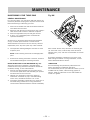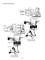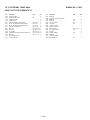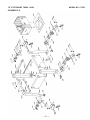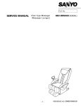
1
Model
C 10FL
Stationary Table Saw
INSTRUCTION MANUAL AND SAFETY INSTRUCTIONS
WARNING
Improper and unsafe use of this power tool can result in death or serious bodily injury!
This manual contains important information about product safety. Please read and understand
this manual before operating the power tool. Please keep this manual available for others before
they use the power tool.
CONTENTS
SECTION
PAGE
Product Specifications ............................................................ 3
Power Tool Safety ................................................................... 4
Table Saw Safety .................................................................... 5
Electrical Requirements and Safety ...................................... 6
Accessories and Attachments ............................................... 7
Tools Needed For Assembly .................................................. 7
Carton Contents ..................................................................... 8
SECTION
PAGE
Know Your Stationary Table Saw ........................................ 10
Glossary of Terme ................................................................. 11
Assembly and Adjustments ................................................. 12
Operation ............................................................................... 19
Maintenance .......................................................................... 23
Troubleshooting Guide ......................................................... 25
Push Stick Pattern ................................................................. 26
Parts List ................................................................................ 28
HITACHI AUTHORIZED SERVICE CENTERS
Service under this warranty is available from Hitachi Koki U.S.A., Ltd. at :
IN THE U.S.A.
IN CANADA
6395 Kestrel Road Mississauga ON L5T 1Z5
3950 Steve Reynolds Blvd. Norcross, GA 30093
9409 Owensmouth Ave. Chatsworth, CA 91311
OR CALL: (800) 546-1666 for a service center nearest you. OR CALL: (800) 970-2299 for a service center nearest you.
— 2—
WARNING
Some dust created by power sanding, sawing, grinding, drilling and other construction activities contains chemicals
known to the state of California to cause cancer, birth defects or other reproductive harm. Some examples of these
chemicals are:
• Lead from lead-based paints
• Crystalline silica from bricks, cement and other masonry products
• Arsenic and chromium from chemically treated lumber
Your risk from these exposures varies, depending on how often you do this type of work. To reduce your exposure to
these chemicals, work in a well-ventilated area and work with approved safety equipment such as dust masks that are
specially designed to filter out microscopic particles.
PRODUCT SPECIFICATIONS
MOTOR
HP (Maximum developed) ............ 3.0
Type ................................................ Induction
Amps .............................................. 15 / 7.5
Voltage ........................................... 120 / 240
Hz .................................................... 60
RPM (no load) ................................ 3450
Overload Protection ...................... YES
SAW
Table Size ....................................... 27-1/8” x 20-1/8”
Table Extensions ........................... Left & Right
Extension Fence Capacity ............. 24” Left & Right
Blade Size ....................................... 10”
Rip Scale ........................................ YES
Rip Fence ........................................ YES
Miter Gauge ................................... YES
Maximum Cut Depth @ 90° .......... 3-3/8”
Maximum Cut Depth @ 45° .......... 2-1/4”
Maximum Dado Cut Width ........... 13/16”
Net Weight ..................................... 264.5 LBS
WARNING
To avoid electrical hazards, fire hazards or damage to the table saw, use proper circuit protection.
This table saw is wired at the factory for 110-120/220-240 Volt operation. It must be connected to a 110-120 Volt / 15
Ampere or 220-240 Volt / 7.5 Ampere time delay fuse or circuit breaker. To avoid shock or fire, replace power cord
immediately if it is worn, cut or damaged in any way.
Before using your table saw, it is critical that you read and understand these safety rules. Failure to follow these rules
could result in serious injury to you or damage to the table saw.
—3—
POWER TOOL SAFETY
WARNING
Before using your table saw, it is critical that you read and understand these safety rules. Failure to follow these rules
could result in serious injury or damage to the table saw.
Good safety practices are a combination of common
sense, staying alert and understanding how to use your
power tool. To avoid mistakes that could cause serious
injury, do not plug in your power tool until you have read
and understood the following safety rules:
1.
2.
READ and become familiar with this entire Operator’s
Manual. LEARN the tool’s applications, limitations and
possible hazards.
4.
16. NEVER LEAVE TOOL RUNNING UNATTENDED.
TURN THE POWER “OFF”. Do not leave the tool
before it comes to a complete stop.
17. NEVER STAND ON TOOL. Serious injury could occur if
the tool is tipped or if the cutting tool is
unintentionally contacted.
WARNING
Look for this symbol that identifies important safety
precautions. It means CAUTION! BECOME ALERT!
YOUR SAFETY IS INVOLVED!
3.
15. REMOVE ADJUSTING KEYS AND WRENCHES.
Form the habit of checking to see that keys and
adjusting wrenches are removed from the tool before
turning ON.
18. DO NOT OVERREACH. Keep proper footing and
balance at all times.
NEVER OPERATE THIS MACHINE WITHOUT THE
SAFETY GUARD IN PLACE FOR ALL THROUGH
SAWING OPERATIONS.
19. MAINTAIN TOOLS WITH CARE. Keep tools sharp and
clean for most efficient and safest performance.
Follow instructions for lubricating and changing
accessories.
DO NOT USE IN A DANGEROUS ENVIRONMENT
such as damp or wet locations or exposure to rain.
Keep work area well lighted.
5.
DO NOT use power tools in the presence of flammable
liquids or gases.
6.
KEEP WORK AREA CLEAN. Cluttered areas and
benches invite accidents.
7.
KEEP CHILDREN AWAY. All visitors should be kept at
a safe distance from the work area.
8.
DO NOT FORCE THE TOOL. It will do the job better
and safer at the rate for which it was designed.
9.
USE THE RIGHT TOOL. Don’t force the tool or
attachment to do a job for which it is not designed.
20. CHECK FOR DAMAGED OR LOOSE PARTS.
Before further use of the tool, a guard or other part
that is damaged should be carefully checked to ensure
it will operate properly and perform its intended
function. Check for alignment of moving parts, loose
binding of moving parts, mounting and any other
conditions that may affect its safe operation. A guard
or other part that is loose or damaged should be
properly adjusted repaired or replaced.
21. MAKE WORKSHOP CHILD PROOF with padlocks,
master switches or by removing starter keys.
22. DO NOT operate the tool if you are under the
influence of any drugs, alcohol or medication that
could impair your ability to use the tool safely.
10. WEAR PROPER APPAREL. DO NOT wear loose
clothing, gloves, neckties, rings, bracelets or other
jewelry that may get caught in moving parts. Non-slip
footwear is recommended. Wear protective hair
covering to contain long hair.
23. USE DUST COLLECTION SYSTEM wherever possible.
Dust generated from certain materials can be
hazardous to your health and in some cases, a fire
hazard. Always operate the power tool in a wellventilated area with adequate dust removal.
11. WEAR A FACE MASK OR DUST MASK. Sawing,
cutting and sanding operations produce dust.
24. ALWAYS WEAR EYE PROTECTION. Any power tool
can throw foreign objects into your eyes that could
cause permanent eye damage. ALWAYS wear safety
goggles (not glasses) that comply with ANSI safety
standard Z87.1. Everyday glasses have only impact
resistant lenses. They ARE NOT safety glasses.
NOTE: Glasses or goggles not in compliance with
ANSI Z87.1 could cause serious injury when they
break.
12. DISCONNECT TOOLS before servicing and when
changing accessories such as blades, cutters, etc.
13. REDUCE THE RISK OF UNINTENTIONAL STARTING.
Make sure the switch is in the OFF position before
plugging into the power supply.
14. USE ONLY RECOMMENDED ACCESSORIES.
Consult the Operator’s Manual for recommended
accessories. The use of improper accessories may
cause injury to you or damage to the tool.
25. DIRECTION OF FEED. Feed work into a blade or cutter
against the direction of rotation of the blade or cutter
only.
—4—
TABLE SAW SAFETY
1.
ALWAYS USE SAW BLADE GUARD, splitter and antikickback pawls for every operation for which they can
be used, including through sawing. Through sawing
operations are those in which the blade cuts
completely through the workpiece when ripping or
crosscutting.
2.
ALWAYS HOLD WORK FIRMLY against the miter
gauge or rip fence.
3.
USE A PUSH STICK when required. Always use a
push stick especially when ripping narrow stock. Refer
to ripping instructions in this Operator’s Manual
where the push stick is covered in detail. A pattern for
making your own push stick is included on page 26.
12. PROVIDE ADEQUATE SUPPORT to the rear and the
sides of the saw table for long or wide workpieces.
13. AVOID KICKBACKS (work thrown back towards you)
by keeping the blade sharp, the rip fence parallel to
the saw blade and by keeping the splitter, antikickback pawls and guards in place, aligned and
functioning. Do not release work before it has passed
all the way past the saw blade. Do not rip work that is
twisted, warped or does not have a straight edge to
guide it along the fence.
14. AVOID AWKWARD OPERATIONS and hand positions
where a sudden slip could cause your hand to move
into the saw blade.
NEVER PERFORM ANY OPERATION “FREE HAND”,
which means using only your hands to support or
guide the workpiece. Always use either the fence or
the miter gauge to position and guide the work.
15. NEVER USE SOLVENTS to clean plastic parts.
Solvents could possibly dissolve or otherwise damage
the material. Only a soft damp cloth should be used to
clean plastic parts.
WARNING: FREEHAND CUTTING IS THE MAJOR
CAUSE OF KICK-BACK & FINGER/HAND
AMPUTATIONS.
16. MOUNT your table saw on a bench or stand before
performing any cutting operations. Refer to
ASSEMBLY AND ADJUSTMENTS on page 12.
5.
NEVER STAND or have any part of your body in line
with the path of the saw blade. Keep your hands out
of the saw blade path.
17. NEVER CUT METALS or materials which may make
hazardous dust.
6.
NEVER REACH behind or over the cutting tool for any
reason.
7.
REMOVE the rip fence when crosscutting.
8.
DO NOT USE a molding head with this saw.
9.
FEED WORK INTO THE BLADE against the direction of
rotation only.
4.
10. NEVER use the rip fence as a cut-off gauge when
crosscutting.
11. NEVER ATTEMPT TO FREE A STALLED SAW BLADE
without first turning the saw OFF. Turn power switch
OFF immediately to prevent motor damage.
18. ALWAYS USE IN WELL-VENTILATED AREA.
Remove sawdust frequently. Clean out sawdust from
the interior of the saw to prevent a potential fire
hazard. Attach a vacuum to the dust port for
additional sawdust removal.
19. NEVER LEAVE THE SAW running unattended. Do not
leave the saw until it comes to a complete stop.
20. For proper operation follow the instructions in this
Operator’s Manual entitled ASSEMBLY AND
ADJUSTMENTS (Page 12). Failure to provide sawdust
fall-through and removal hole will allow sawdust to
build up in the motor area resulting in a fire hazard
and potential motor damage.
—5—
ELECTRICAL REQUIREMENTS AND SAFETY
POWER SUPPLY REQUIREMENTS
GROUNDING INSTRUCTIONS
WARNING
To avoid electrical hazards, fire hazards or damage to the
table saw, use proper circuit protection. Always use a
separate electrical circuit for your tools. This power tool
is wired at the factory for 120V operation. Connect it to a
120V, 15 Amp circuit and use a 15 Amp time delay fuse or
circuit breaker. To avoid shock or fire, replace the cord
immediately if it is worn, cut or damaged in any way.
EXTENSION CORD REQUIREMENTS
Any extension cord must be GROUNDED for safe
operation.
MINIMUM GAUGE FOR EXTENSION CORDS
(AWG type / 120 Volt only)
Not
More Than More Than
0
6
6
10
10
12
12
16
CHECK with a qualified electrician or service personnel if
you do not completely understand the grounding
instructions, or if you are not sure the saw is properly
grounded.
Total length in feet
25’
18
18
16
14
DO NOT MODIFY THE PLUG PROVIDED. If it will not fit the
receptacle, have the proper receptacle installed by a
qualified electrician.
IMPROPER CONNECTION of the equipment grounding
conductor can result in risk of electric shock. The
conductor (wire) with the green insulation (with or without
yellow stripes) is the equipment grounding conductor. If
repair or replacement of the electric cord or plug is
necessary, DO NOT connect the equipment grounding
conductor to a live terminal.
WARNING
Ampere Rating
IN THE EVENT OF A MALFUNCTION OR BREAKDOWN,
grounding provides a path of least resistance for electric
current and reduces the risk of electric shock. This saw is
equipped with an electric cord that has an equipment
grounding conductor and a grounding plug. The plug
MUST be plugged into a matching receptacle that is
properly installed and grounded in accordance with ALL
local codes and ordinances.
50’
100’
150’
AWG
16
16
14
16
14
12
16
14
12
12
Not Applicable
Use only 3-wire extension cords that have 3-prong
grounding plugs and 3-pole grounding receptacles that
accept the saw’s plug. Repair or replace damaged or
worn cords immediately.
3-Prong Plug
GUIDELINES FOR EXTENSION CORDS
Any extension cord used for power tools MUST be
grounded (3-wire with two flat prongs and one round
ground prong).
Make sure the extension cord is in good condition. When
using an extension cord, make sure you use one heavy
enough to carry the current the tool will draw. An
undersized cord will cause a drop in line voltage resulting
in loss of power and overheating. The table above shows
the correct size to use according to extension cord length
and nameplate ampere rating. If in doubt, use the next
heavier gauge cord. The smaller the gauge number the
heavier the cord.
NOTE: The 12 to 16 Amp rating is correct for this tool. It is
highlighted in the table above.
Be sure your extension cord is properly wired and in good
condition. Always replace a damaged extension cord or
have it repaired by a qualified person before using it.
Protect your extension cords from sharp objects,
excessive heat and damp or wet areas.
Before connecting the saw to the extension cord, make
sure the saw switch is turned OFF.
—6—
Grounding Prong
Properly Grounded
3-Prong Receptacle
Grounding Lug
Make Sure This
is Connected to a
Known Ground
Adapter
2-Prong
Receptacle
ACCESSORIES AND ATTACHMENTS
RECOMMENDED ACCESSORIES
WARNING
Visit your Hardware Department or see the Power and
Hand Tools Catalog to purchase recommended
accessories for this power tool.
WARNING
To avoid the risk of personal injury:
Do not use a dado with a diameter larger than 8".
Maximum dado width is 13/16". DO N OT U S E W IDE R
COMBINATIONS.
Do not use molding head set with this saw.
Do not modify this power tool or use accessories not
recommended by Store.
TOOLS NEEDED FOR ASSEMBLY
TOOLS NEEDED
Medium screwdriver
Adjustable wrench
#2 Philips screwdriver
Straight edge
Combination square
4mm Hex wrench
5mm Hex wrench
17mm Hex wrench
—7 —
CARTON CONTENTS
UNPACKING AND CHECKING CONTENTS
WARNING
WARNING
Separate all parts from packing materials. Check each part
with the illustration on the next page and the “Table of
Loose Parts” to make certain all items are accounted for,
before discarding any packing material.
If any part is missing or damaged, do not attempt to
assemble the table saw, plug in the power cord, or turn
the switch ON until the missing or damaged part is
obtained and is installed correctly.
TABLE OF LOOSE PARTS
ITEM
DESCRIPTION
QUANTITY
A.
B.
C.
D.
E.
F.
G.
H.
I.
J.
K.
L.
M.
N.
O.
P.
Q
Table saw assembly
Table extension wing
Rear table extension rail
Front table extension rail
Rail cover
Blade guard and splitter
Adhesive washer
Rip fence
Miter gauge
Dust chute
Blade wrench
Push stick
Dodo table insert
Blade
Handwheel handle & nuts
Handwheel and handle
Table extension hardware
Square nut
Hex hd. bolt
M8x1.25-16
Hex hd. bolt
M8x1.25-20
Hex.socket hd.cap bolt M8x1.25-16
Hex hd. bolt & washer M10x1.5-25
1
2
2
2
6
1 each
5
1
1
1
1
1
1
1
1 each
1
STAND
V.
W.
X.
Y.
Z.
AA.
BB.
CC.
DD.
EE.
Top leg bracket
Bottom leg bracket
Leg
Leg front bracket
R & L leg bracket
Foot and hardware
Storage bracket & foot hardware
Caster assemblies A
Caster assemblies B
Stand & caster mounting hardware
1
1
4
1
1 each
1 set
1 set
2
2
36
NOTE: To make assembly easier, keep contents of box
together. Apply a coat of automobile wax to the table.
Wipe all parts thoroughly with a clean dry cloth. This will
reduce friction when pushing the workpiece.
6
2
4
6
6
—8—
UNPACKING YOUR STATIONARY TABLE SAW
N
I
H
E
A
J
P
G
O
F
D
K
C
B
AA
EE
L
Q
M
BB
CC
DD
V
W
X
Y
—9—
Z
KNOW YOUR STATIONARY TABLE SAW
Blade Guard
Rip Fence
Blade Tilt Scale
Miter Gauge
Table Extension
(Left)
Table Extension
(Right)
Blade Tilting
Handwheel
Blade Elevation
Handwheel
ON/OFF Switch
with key
Leg Stand
Castar
Table Insert
Splitter
Table
Miter Gauge
Storage
Rip Fence
Storage
— 10 —
GLOSSARY OF TERMS
HITACHI PROFESSIONAL
TABLE SAW TERMS
CROSSCUT - A cut made across the width of the
workpiece.
MITER GAUGE - A guide used for crosscutting operations
that slides in the tabletop channels located on either side
of the blade. It helps make accurate straight or angle cuts.
FREEHAND - Performing a cut without using a fence
(guide), hold down or other proper device to prevent the
workpiece from twisting during the cutting operation.
RIP FENCE - A guide used for rip cutting that clamps to
the tabletop. It allows the workpiece to be straight.
GUM - A sticky sap from wood products.
HEEL - Misalignment of the blade.
TABLE INSERT - Provides access to the blade arbor for
changing blades.
KERF - The amount of material removed by a blade cut.
OVERLOAD RESET SWITCH - Resets the thermocouple
and provides a way to restart the saw motor if it overheats
or overloads.
BLADE BEVEL SCALE - Measures the angle the blade is
tilted when set for a bevel cut.
MITER CUT - An angle cut made across the width of the
workpiece.
RESIN - A sticky sap that has hardened.
REVOLUTIONS PER MINUTE (RPM) - The number of turns
completed by a spinning object in one minute.
TABLE SCALE - Measures the distance the rip fence is set
from the blade, allowing quick setups.
ANTI-KICKBACK PAWLS - Prevents the workpiece from
being kicked upward or back toward the front of the table
saw by the spinning blade.
SPLITTER - Keeps the workpiece spread apart after being
cut, to prevent binding on the blade and workpiece.
BLADE ELEVATION HANDWHEEL - Raises and lowers the
blade.
SAW BLADE PATH - The area of the workpiece or table
top directly in line with the travel of the blade or the part
of the workpiece that will be cut.
SET - The distance between two saw blade tips, bent
outward in opposite directions to each other. The further
apart the tips are, the greater the set.
WORKPIECE - The item being cut. The surfaces of a
workpiece are commonly referred to as faces, ends and
edges.
Leading Edge
BLADE TILTING HANDWHEEL - Tilts the blade to any
angle between 0 to 45 for bevel cuts.
Kerf
Sawblade Path
WOODWORKING TERMS
Surface
ARBOR - The shaft on which a blade is mounted.
BEVEL CUT - An angle cut made through the face of the
workpiece.
COMPOUND CUT - A simultaneous bevel and miter cut.
W orkpiece
— 11 —
Trailing Edge
ASSEMBLY AND ADJUSTMENTS
ESTIMATED ASSEMBLY TIME 50~70 MINUTES (2 PEOPLE)
ASSEMBLE STAND (Fig. A)
1. Unpack all parts and group by type and size (Fig. A).
Refer to parts list for quantities.
2. Attach one support (4) to leg (1) using one square
neck bolt (2) and nut (3).
NOTE: Do not tighten bolts until stand is properly
aligned (see step # 7).
3. Attach other end of support to another leg using one
square neck bolt and nut.
4. Join front frame assemblies using support (5) square
neck bolts and nuts.
5. Join rear frame assemblies using short upper support
(6) and short bottom support (7), square neck bolts
and nuts.
6. Place three rubber feet (8) onto three leg and the
adjustable foot (9) and nut (10) onto the bracket of the
other leg.
7. Attach the hooks (11) and power cord storage (12) to
the frame as desired. The hooks are used to hold the
fence.
8. Place stand on level surface and adjust so all legs are
contacting the floor and are at similar angles to the
floor.Tighten all bolts.
NOTE : Stand should not rock after all bolts are
tightened.
9. Mounting a caster (13) on each leg by tightening three
bolts (14) and nuts (15). Four casters.
NOTE: Two casters marked "A " are us ed for the FrontRight & Rear-Left legs, two casters marked "B " are
used for the Front-Left & Rear-Right legs.
ASSEMBLE TABLE SAW TO STAND (Fig. A, B)
1. Place protective corrugated cardboard or old blanket
on floor to protect the saw table surface.
2. Place the saw up-side down on the protective material
(Fig. B).
3. Position the recessed-side dust chute and the stand
up-side down on the saw base.
NOTE: Make sure front of stand and front of saw are
facing the same direction.
4. Line up four holes in saw base, dust chute and stand.
5. Fasten saw to dust chute and stand using four bolts,
washers and nuts.
NOTE: Place washer on each bolt before inserting into
saw base and through the support. Nut must be flush
against the bracket.
6. Tighten all four nuts.
NOTE: Do not overtighten the locknuts mounting the
base to the stand (you may damage the base).
7. Carefully set the saw in its upright position on a clean
level surface.
8. Push down on the lever of right wheel assemblies to
unlock. Push up on the lever of right wheel assemblies
to lock.
NOTE: You will need assistance form another person.
Fig. B
Fig. A
Leg set
mounting
hole
1
12
6
4
Dust chute
mounting
hole
3
2
1
7
3
Saw base
hole
3
10
9
1
4
5
3
1
15
11
13
8
14
— 12 —
ASSEMBLY THE TABLE EXTENSION (Fig. C)
1. Place the left table extension next to the saw table,
aligning the mounting holes (1).
2. Place bolts (2) and thread in mounting holes.
3. Place a straight edge or combination square on the
saw table, across the table extension.
4. Adjust the mounting bolts (2) until the extension is
flush with the saw table. Tighten.
5. Repeat these procedures for the right extension table.
Fig. C
Assembly the rear table rail (Fig. E)
6. Attach the side covers (1) and middle plug (2) to the
rear table rails (3).
7. Place the rear table rails on the saw table, aligning
with the holes in each rail.
8. Place the bolts (4) and tread in the holes; tighten the
bolts and check the alignment again.
Fig. E
4
1
3 1
2
2
BLADE RAISING HANDWHEEL (Fig. F)
Thread the blade handwheel handle (1) into blade raising
handwheel (2) and tighten.
ASSEMBLY THE FRONT AND REAR TABLE RAIL
(Fig. D, E)
NOTE: Front of table rails assemblies are different.
Assembly the front rail (Fig. D)
1. Attach the right front side cover (1) into right front
table rail (2). Repeat for the left front rail.
2. Place the hex. bolts M8-20 (3), hex bolts M8-16 (4)
through the holes at the front table edge. Screw the
square nuts (5) onto each bolts.
NOTE: Keep the bolts and square nuts loosened
before front rail fixed.
3. Attach the right front rail onto proper location by
having the square nuts pass through the slot of the
front rail. Repeat for the left front rail.
4. Attach the middle plug (6) to connect the two half
front rail. (Fig. E)
5. When the blade was installed, use the rip fence and
gauge to adjust the front rail to proper location. When
the front rail is level with table, then fix the front rail
by tightening the six bolts.
BLADE TILTING HANDWHEEL (Fig. F)
1. Attach the blade tilting handwheel (3) to the elevation
screw at the front of the saw.
2. Attach and tighten the dome nut (4) at the end of the
shaft.
Fig. F
1
3
Fig. D
5
2
4
BLADE GUARD ASSEMBLY (Fig. G, H)
4
WARNING
3
4
6
2
1
To avoid injury from an accidental start, make sure the
switch is in the OFF position and the plug is disconnected
from the power source outlet.
When installing the blade guard, cover the blade teeth
with a piece of folded cardboard to protect yourself
from possible injury.
Never operate this machine without the safety guard
in place for all through sawing operations.
— 13 —
Installing the blade guard assembly (Fig. G)
1. Remove the table insert.
2. Unlock the blade bevel lock knob (1).
3 With the blade evevation handwheel (2), raise the
blade to the maximum height.
4. Using the blade tilting handwheel, tilt the blade to
45 on the bevel scale.
5. Lock the blade tilt locking knob.
6. Locate the splitter assembly mounting bracket (4) in
back of the blade.
7. Cover the blade teeth with a folded cardboard or
position the plastic blade guard over the blade to
protect your hands.
8. Place the two kickback pawls (5) toward the rear of the
table, and align the splitter mounting holes to the
holes in the bracket.
9. Place the steel flat washers (6) on the two bolts (7) and
tread the bolts into the holes.
10. Tighten the bolts with the angled wrench.
Note: Make sure the "anti-kick back pawls" do not get
caught between the insert and the guard, but rest on top
of the insert.
Fig. G
4
6
5
1
2
45
0
BLADE
ANGLE
ADJUSTMENT
UP
7
UP
Removing the blade guard assembly (Fig. H)
WARNING
To avoid injury from an accidental start, make sure the
switch is in the OFF position and the plug is disconnected
from the power source outlet.
1. Remove the table insert.
2. With the blade elevation handwheel (1), raise the
blade to the maximum height.
3. Loosen blade lock handle (2) and move the handwheel
(1) to 45 on the bevel scale.
4. Tighten the bevel lock handle.
5. Cover the blade teeth with a piece of folded cardboard
or position the plastic blade guard over the blade to
protect your hands.
6. Loosen the knob (5) and remove the blade guard
assembly, then retighten the knob.
7. Return the blade to 90 and replace the table insert.
Note: Make sure the "anti-kick back pawls" do not get
caught between the insert and the guard, but rest on top
of the insert.
ALIGNING THE BLADE GUARD SPLITTER (Fig. H)
WARNING
To avoid injury from an accidental start, make sure the
switch is in the OFF position and the plug is disconnected
from the power source outlet.
When installing the blade guard, cover the blade teeth
with a piece of folded cardboard to protect yourself
from possible injury.
Never operate this machine without the safety guard
in place for all through sawing operations.
IMPORTANT: The splitter must always be correctly
aligned with the blade so the cut workpiece will pass on
either side without binding or twisting.
1. Remove the table insert and raise the blade to the
maximum height by turning the blade elevation
handwheel clockwise.
2. Lift the blade guard and pos ition it toward the rear of
the table.
3. Adjust the blade to the 90 vertical position by
unlocking the blade tilting lock knob and turning the
bevel tilting handwheel counterclockwise, and then
lock into position.
4. To see if the blade (1) and splitter (2) are correctly
aligned, lay a combination square along the side of
the blade and against the splitter (making sure the
square is between the teeth of the blade).
5. Tilt the blade to the 45 position and check the
alignment again.
6 If the blade and splitter are not correctly aligned:
a. Remove the blade guard by removing the wing
bolt that locks the guard in place.
b. Loosen and remove the two bolts (3) from the
mounting bracket (7).
7. Place two adhesive washers (5) on the guard
mounting bracket (attached to the saw). Position
them over the corresponding mounting bolt holes
(refer to step 6-b) after removing the adhesive backing
affixed to the washers.
8. Replace the two guard mounting bolts (3) and tighten
securely. Also reattach the blade guard assembly,
affixing it to the machine by its corres ponding wing
bolt.
9. Check the splitter and blade alignment again at both
90 and 45 .
10. Add or remove the adhesive washers until the
alignment is correct.
11. Replace the table insert.
Fig. H
7
2
1
— 14 —
5
2
3
REMOVING THE BLADE (Fig. I)
WARNING
To avoid injury from an accidental start, make sure the
switch is in the OFF position and the plug is disconnected
from the power source outlet.
1. Remove the table insert and raise the blade to the
maximum height by turning the blade elevation
handwheel clockwise.
2. Lift the blade guard and position it toward the rear of
the table.
3. Adjust the blade to the 90 vertical position by
unlocking the blade tilting lock knob and turning the
bevel tilting handwheel counterclockwise, and then
lock into position.
4. Pull the motor locking lever (1) toward the front of the
machine while spinning the blade until the latch locks
into place and the blade will no longer turn.
5. Place the blade wrench (3) on the arbor nut (4).
6. Loosen and remove the arbor nut and the flange by
pulling the wrench toward the front of the machine
(5).
7. Then remove the blade (6). Clean but do not remove
the inner blade flange (5) before reassembling the
blade.
Fig. I
6. Place the wrench on the arbor nut and turn clockwise
(toward the rear of the saw table).
7. Replace the table insert and blade guard assembly.
Verify that the blade and blade guard splitter are
aligned. If they are not, refer to page 14, Aligning The
Blade Guard Splitter.
IMPORTANT: Do not operate this saw until the blade and
blade guard splitter are aligned and in working order.
ADJUSTING THE 90 AND 45 POSITIVE STOPS
(Fig. J, K)
Your saw has positive stops that will quickly position the
saw blade at 90 and 45 to the table. M ake adjus tm ents
only if necessary.
90
1.
2.
3.
4.
5.
6.
3
4
7.
6
1
8.
9.
Stop
Remove the table insert.
Disconnect the saw from the power source.
Raise the blade to the maximum elevation.
Loosen the blade bevel lock handle and move the
blade to the maximum vertical position and tighten
the bevel lock handle.
Place a combination square on the table and against
the blade (1) to determine if the blade is 90 to the
table. (Fig. J)
If the blade is not 90 to the table, loosen or tighten
(depending on increasing or decreasing the degree)
the hex screw (3) with a 5mm hex wrench until you
achieve 90 . (Fig. K)
The, re-loosen the bevel lock handle and reset the
blade at the maximum vertical position, then tighten
the bevel lock handle.
Check again to see if the blade is 90 to the table. If
not, repeat step 5.
Lastly, check the bevel angle scale. If the pointer does
not read 90 , loosen the screw holding the pointer and
move the pointer so it is accurate at 0 and retighten
the pointer screw.
Fig. J
90
45
5
INSTALLING A BLADE (Fig. I)
WARNING
1
To avoid injury from an accidental start, make sure the
switch is in the OFF position and the plug is disconnected
from the power source outlet.
1. Place the blade onto the arbor with the blade teeth
pointing forward to the front of the saw.
2. Make sure the blade fits flush against the inner flange.
3. Clean the outer blade flange and install it onto the
arbor and against the blade.
4. Thread the arbor nut onto the arbor, making sure the
flat side of the nut is against the blade, then handtighten.
5. Pull the motor locking lever (1) toward the front of the
machine while spinning the blade until the latch locks
into place and the blade will no longer turn.
45
1.
2.
3.
2
Stop
Disconnect the saw from the power source.
Raise the blade to the maximum elevation.
Loosen the blade bevel lock handle and move the
blade to the maximum bevel position (45 ) and tighten
the bevel lock handle.
4. Place a combination square on the table and against
the blade (1) to determine if the blade is 45 to the
table. (Fig. J)
5. If the blade is not 45 to the table, loosen or tighten
(depending on increasing or decreasing the degree)
the hex screw (4) with a 5mm hex wrench until you
achieve 45 . (Fig. K)
— 15 —
6.
7.
The, re-loosen the bevel lock handle and reset the
blade at the maximum bevel position (45°), then
tighten the bevel lock handle.
Check again to see if the blade is 45° to the table. If
not, repeat step 5.
BLADE PARALLEL TO THE MITER GAUGE GROOVE (Fig. M)
To avoid injury from an accidental start, make sure the
switch is in the OFF position and the plug is disconnected
from the power source outlet.
This adjustment was made at the factory, but it should be
rechecked and adjusted if necessary.
This adjustment must be correct or kickback could result
in a serious injury and accurate cuts cannot be made.
Fig. K
1.
2.
3.
4.
4
3
5.
6.
7.
8.
BLADE TILTING INDICATOR (Fig. L)
1. When the blade is positioned at 90°, adjust the blade
tilt pointer to read 0° on the scale.
2. Remove the magnifier, position the pointer over 0°
and replace the magnifier.
NOTE: Make a trial cut on scrap wood before making
critical cuts. Measure for accuracy.
9.
Remove the yellow switch key and unplug the saw.
Raise the blade guard away from the blade.
Raise the blade to the maximum height and set the
belel angle at 0°.
Select and mark with a felt tip marker, one blade tooth
with a “right set” angle and position this tooth at the
front of the saw approximately 1/2” above the table.
Place the combination square base (1) into the right
side miter gauge groove (2) flush against the inside of
the miter gauge groove. (Fig. M)
Adjust the ruler so it touches the front marked tooth
and lock ruler so it holds its position in the square
assembly.
Rotate the blade to the rear of the saw bringing the
marked tooth approximately 1/2”above the blade.
Carefully slide the combination square to the rear until
the ruler touches the marked tooth.
If the ruler touches the marked tooth at the front and
rear position, no adjustment is needed at this time. If
not, perform adjustment procedure described in next
section.
Fig. M
Fig. L
0°
5° 10°
1
2
— 16 —
INSTALLING THE TABLE INSERT (Fig. N)
The table insert has been previously installed on your
unit. However, you must verify that the table insert is
flush with the table top surface on all four corners of the
insert.
Power Cord (Fig. P)
For convenience and to prevent damage to the power
cord when the table saw is not in use or is being
transported, the frame of leg has two brackets (1) on the
side for cord atorage.
If the table insert is not flush with the table, adjust the four
bolts (1) with a 4mm hex. wrench until it is parallel with
the table.
Note: To raise the insert, turn the hex screws
counterclockwise, to lower the insert, turn the hex screws
clockwise.
Fig. P
1
Fig. N
1
STORAGE (Fig. O, P)
Rip fence and miter gauge (Fig. O)
Storage brackets for the rip fence (2) and miter gauge (1)
are located on the right side of the saw housing and frame
of leg.
Fig. O
1
MITRE GAUGE ADJUSTMENT (Fig. Q)
1. Make sure that the mitre gauge bar (1) will slide freely
through the table top grooves.
2. Loosen the lock knob handle (2) and turn the gauge
body (3) to set the pointer (4) at 0 on the s cale.
3. Make a 90 cut in a scrap piece of wood. Check the cut
to see if it is 90. If not, loosen the lock knob handle (2)
and move the mitre gauge body until it is square to the
miter gauge bar by using a combination square.
MITRE GAUGE OPERATION (Fig. Q)
The mitre gage is accurately construted with index stops
at 0 , 15 , 30 , 45 , 60 both right and left side.
The operate the mitre gage, simply loosen the lock handle
(2) and move the body of the mitre gauge to the desired
angle. The mitre gauge body will stop at 0 , 15 , 30 , 45 ,
60 both right and left side.
Fig. Q
1
2
3
2
4
— 17 —
RIP FENCE ADJUSTMENT (Fig. R)
1. For adjustments, position the fence to the right of the
blade, parallel with the miter gauge groove.
2. Place the rear clamp (1) of the fence on the back rail of
the table, and lower the front end over the front rail
(2). Push the handle (3) down to lock.
3. To change the position of the fence, lift up on the
handle to unlock, and slide the fence to the desired
position, then push the handle down to lock.
Fig. R
RIP FENCE INDICATOR (Fig. T)
NOTE: The rip fence indicator points to the scale on the
front of the table saw. Measurement shown by the
indicator will provide the user with accuracy up to 1/16 of
an inch. Measurement shown is the distance from the
blade to the side of the fence closest to the blade.
1.
2.
To check the accuracy, measure the actual distance to
the side of the rip fence. If there is a difference
between the measurement and the indicator, adjust
the indicator as shown next.
Loosen the indicator screws (1). Slide the indicator to
the correct measurement position on the scale, then
retighten the indicator screws (1).
Fig. T
1
2
3
12
If the fence is loose when the handle is in the locked
position: (Fig. S)
1. Move the handle upward to the unlocked position.
Turn the adjusting screw (4) clockwise until the rear
clamp is snug.
2. DO NOT turn the adjusting screw more than 1/4 turn
at a time.
3. Over-tightening the screw will cause the rip fence to
come out of alignment.
WARNING
Failure to properly align the fence can cause "kickback"
and serious injury could occur.
16
13
23
20
24
25
PU S H
M icro
A dju s tm ent
2
RIP FENCE OPERATION
The rip fence moves to either side of saw blade. The right
side is the most common position. Front and rear guide
the fence. Calibrations on the front guide rail show
distance between fence and saw blade.
To adjust rip fence, raise clamp lever to maximun height,
push fence desired distance from saw blade, and turning
micro-set knob (2) left or right.
Fig. S
4
1
1
— 18 —
OPERATION
BASIC SAW OPERATIONS
Fig. V
RAISE THE BLADE (Fig. U)
To raise or lower the blade, turn the blade elevation
handwheel (1) to the desired blade height, and then
tighten the bevel lock handle (2) to maintain the desired
blade angle.
1
Fig. U
1
2
2
3
3
TILTING THE BLADE
1. To tilt the saw blade for bevel cutting, loosen the lock
knob (2) and turn the tilting handwheel (3).
2. Tighten the lock knobs (2) to secure.
ON / OFF SWITCH (Fig. V)
The ON / OFF switch has a removal key. With the key
removed from the switch, unauthorized and hazardous
use by children and others is minimized.
1. To turn the saw ON, lift swich cover (1) and insert the
safety switch key (2) into the slot in the switch.
Move the switch (3) upward to the ON position.
2. To turn the saw OFF, move the switch downward.
3. To lock the switch in the OFF position, grasp the end
(or yellow part) of the safety switch key, and pull it out.
4. With the safety switch key removed, the switch will
not operate.
5. If the safety switch key is removed while the saw is
running, it can be turned OFF but cannot be restarted
without inserting the safety switch key.
OVERLOAD PROTECTION
This saw has an overload relay button that resets the
motor after it shuts off due to overloading or low voltage.
If the motor stops during operation, turn the ON / OFF
switch to the OFF position. Wait about five minutes for the
motor to cool, push in on the reset button and turn the
switch to the ON position.
CUTTING OPERATIONS
There are two basic types of cuts: ripping and
crosscutting. Ripping is cutting along the length and the
grain of the workpiece. Crosscutting is cutting either
across the width or across the grain of the workpiece.
Neither ripping nor crosscutting may be done safely
freehand. Ripping requires the use of the rip fence, and
crosscutting requires the miter gauge.
WARNING
Before using the saw each and every time, check the
following:
1. The blade is tightened to the arbor.
2. The bevel angle lock knob is tight.
3. If ripping, the fence is locked into position & is parallel
to the miter gauge groove.
4. The blade guard is in place and working properly.
5. Safety glasses are being worn.
The failure to adhere to these common safety rules, and
those printed in the front of this manual, can greatly
increase the likelihood of injury.
— 19 —
RIPPING (Fig. W, X)
WARNING
Keep your thumbs off the table top. When both of
your thumbs touch the front edge of the table (2),
finish the cut with a push stick. To make an additional
push stick, use the pattern on page 26.
8. The push stick (3) should always be used. (Fig. X)
9. Continue pushing the workpiece with the push stick
(3) until it passes through the blade guard and clears
the rear of the table.
10. Never pull the piece back when the blade is turning.
Turn the switch OFF. When the blade completely
stops, you can then remove the workpiece.
7.
To prevent serious injury:
Never use a miter gauge when ripping.
Do not allow familiarity or frequent use of your table
saw to cause careless mistakes. Remember that even
a careless fraction of a second is enough to cause a
severe injury.
Keep both hands away from the blade and clear from
the path of the blade.
The workpiece must have a straight edge against the
fence and must not be warped, twisted, or bowed
when ripping.
Fig. X
1. Remove the miter gauge and store it in the "storage"
compartment in the base of the saw.
2. Secure the rip fence to the table.
3. Raise the blade so it is about 1/8" higher than the top
of the workpiece.
4. Place the workpiece flat on the table and against the
fence. Keep the workpiece away from the blade.
5. Turn the saw ON and wait for the blade to come to
full speed.
6. Slowly feed the workpiece into the blade by pushing
forward only on the workpiece section (1) that will
pass between the blade and the fence. (Fig. W)
PU S H
PU S H
M icro
ent
A dju s tm
M icr o t
tm en
A dju s
3
2
WARNING
1
AVOID KICKBACK by pushing forward on the section of
the workpiece that passes between the blade and the
fence. Never perform any freehand operations.
BEVEL RIPPING
This cut is the same as ripping except the blade bevel
o
angle is set to an angle other than " 0 ".
Fig. W
RIPPING SMALL PIECES
To avoid injury from the blade contact, never make cuts
narrower than 1/2" wide.
1.
2.
PU S H
PU S H
M icr o t
tm en
A dju s
M icro
ent
A dju s tm
1
NOTE: Always use a push stick. When width of the rip is
narrower than 2" the push stick cannot be used because
the guard will interfere... therefore, use the auxiliary fence
so the push stick can be used as shown on page 26.
— 20 —
It is unsafe to rip small pieces. Instead, rip a larger
piece to obtain the size of the desired piece.
When a small width is to be ripped and your hand
cannot be safely press between the blade and the
rip fence, use one or more push sticks to move the
workpiece. Always use a push stick during ripping
operations.
CROSSCUTTING (Fig. Y)
To prevent serious injury:
Do not allow familiarity or frequent use of your table
saw to cause careless mistakes. Remember that even
a careless fraction of a second is enough to cause a
severe injury.
Keep both hands away from the blade and the path of
the blade.
1. Remove the rip fence and place it in the "storage"
compartment of the table saw base.
2. Place the miter gauge either groove in the table top.
3. Adjust the blade height so it is 1/8" higher than the
top of the workpiece.
4. Hold the workpiece firmly against the miter gauge
with the blade path in line with the desired cut
location.
5. Start the saw and wait for the blade (1) to come up to
full speed.
6. Keep the workpiece (2) against the face of the miter
gauge (3) and flat against the table. Then slowly push
the workpiece through the blade. (Fig. Y)
7. Do not try to pull the workpiece back with the blade
turning. Turn the switch OFF, wait for the blade to
come to a complete stop, then carefully slide the
workpiece.
Fig. Y
BEVEL CROSSCUTTING (Fig. AA)
This cutting operation is the same as crosscutting except
the blade is at bevel angle other than 0 .
1. Adjust the blade (1) to the desired angle, and tighten
the blade bevel lock knob.
2. Always work to the left side of the blade. The miter
gauge (3) must be in the left side groove (2).
Fig. AA
1
3
2
COMPOUND MITER CROSSCUTTING (Fig. BB)
This sawing operation is combining a miter angle with a
bevel angle.
1. Set the miter gauge (3) to the desired angle. Use only
the left side groove (2) for this specific operation.
2. Set the blade (1) bevel to the desired angle.
3. Carefully push the miter gauge to begin the cutting
operation.
Fig. BB
3
2
1
2
3
USING WOOD FACING ON THE MITER GAUGE (Fig. Z)
Slots are provided in the miter gauge for attaching an
auxiliary facing (1) to make it easier to cut very long or
short pieces. Select a suitable piece of smooth wood, drill
two holes through it and attach it to the miter gauge with
screws. Make sure the facing does not interfere with the
proper operation of the sawblade guard. When cutting
long workpieces, you can make a simple outfeed support
by clamping a piece of plywood to a sawhorse.
1
MITERING (Fig. CC)
This sawing operation is the same as crosscutting except
the miter gauge is locked at an angle other than 90
1. Hold the workpiece (2) firmly against the miter
gauge (3).
2. Feed the workpiece slowly into the blade (1) to
prevent the workpiece from moving.
Fig. CC
Fig. Z
3
1
— 21 —
2
1
USING WOOD FACING ON THE RIP FENCE (Fig. DD)
When performing some special cutting operations, add a
wood facing (1) to the side of the rip fence between the
fence and the blade where you will be cutting (2).
Attach auxiliary fence to rip fence with two "C" clamps.
(Fig. FF)
Fig. FF
1 . Use a smooth & straight 3/4" thick wood board (1)
measure as long as the rip fence is.
2. Attach the wood facing to the fence with wood screw
(3) through the hole in the fence. A wood fence should
be used when ripping material such as thin paneling
to prevent the material from catching between the
bottom of the fence and the table.
Fig. DD
3
1
2
AUXILIARY FENCE (Fig. EE)
Making the base:
Start with a piece of 3/8" plywood at least 5-1/2" wide
or wider and 30" long or longer.
Cut the piece to shape and size shown:
Making the side:
Start with a piece of 3/4" plywood at least 2-3/8" wide
or wider and 27" long or longer.
Cut the piece to shape and size shown:
Putting it together:
Put the pieces together, as shown:
Make sure the screw heads do not stick out from the
bottom of the base, they must be flush or recessed.
The bottom must be flat and smooth enough to rest on
the saw table without rocking.
For your own safety, always replace the blade, blade
guard assembly, and blade insert when you are finished
with the dado operation.
Fig. GG
Fig. EE
30"
1 -1 /4
3/8" T hick plywood base
5-1/2"
2-5/8"
4 -3
2
"
/4 "
27"
1
3/4" T hick plywood side
2-3/8"
3-1/2"
DADO CUTS (Fig. GG)
1. The dado blade insert is included with this saw.
Remove the saw blade, original table insert and blade
guard. Install the dado and dado blade insert.
2. Instruction for operating the dado is packed with the
separately purchased dado set.
3. The arbor (1) on this saw restricts the maximum width
of the cut to 13/16".
4. When making full 13/16" dado cuts, it is not necessary
to install the outside flange (2) before screwing on the
arbor nut (3). Make sure that the arbor nut (3) is tight,
and that at least one thread of the arbor sticks out past
the nut.
5. Do not exceed 8" diameter dadoes and keep the width
13/16 " or less. It will be necessary to remove the blade
guard and splitter when using a dado blade. Always
use caution when operating a dado blade.
6. Use only the correct number of round outside blades
and inside chippers as shown in the dado set.
instruction manual. Blade or chipper must not exceed
13/16 ".
7. Check saw to ensure that the dado will not strike the
housing, insert, or motor when in operation.
3
— 22 —
MAINTENANCE
MAINTAINING YOUR TABLE SAW
Fig. HH
GENERAL MAINTENANCE
For your own safety, turn the switch OFF and remove the
switch key. Remove the plug from the power source outlet
before maintaining or lubricating your saw.
1. Clean out all sawdust that has accumulated inside the
saw cabinet and the motor.
2. Polish the saw table with an automotive wax to keep it
clean and to make it easier to slide the workpiece.
3. Clean cutting blades with pitch and gum remover.
4. A worn, cut, or damaged power cord should be
replaced immediately.
1
All electrical or mechanical repairs should be attempted
only by a trained repair technician. Contact Hitachi
Authorized Service Center for service. Use only identical
replacement parts. Any other parts may create a hazard.
2
5. Use liquid dish washing detergent and water to clean
all plastic parts.
NOTE: Certain cleaning chemicals can damage plastic
parts.
6.
Avoid use of cleaning chemicals or solvents, ammonia
and household detergents containing ammonia.
BLADE RAISING AND TILTING MECHANISM (Fig. HH)
After each five hours of operation, the blade raising
mechanism and tilting mechanism should be checked for
looseness, binding, or other abnormalities.
1. With the saw disconnected from the power source,
turn the saw upside down and alternately pull upward
and downward on the motor unit.
2. Observe any movement of the motor mounting
mechanism. Looseness or play in the blade raising
screw rod (1) should be limited to 1/8" or less.
3. If excessive looseness is observed in any other part of
the blade raising mechanism or tilting mechanism,
contact Hitachi Authorized Service Center immediately.
Place a small amount of dry lubricant on the bevel gear
(2). The screw rod (1) must be kept clean and free of
sawdust, gum, pitch, and other contaminants for smooth
operation.
If excessive looseness is observed in any parts of the
blade raising mechanism or tilting mechanism, contact
Hitachi Authorized Service Center.
LUBRICATION
All motor bearings are permanently lubricated at the
factory and require no additional lubrication.
On all mechanical parts of your table saw where a pivot or
threaded rod are present, lubricate using graphite or
silicone. These dry lubricants will not hold sawdust as
would oil or grease.
— 23 —
115V & 230V Wire Wirding
Motor
(Terminal Block)
(BLACK)
(BLACK)
(BLACK)
2
(BLACK)
(Rocker Switch)
Blue
1
3
(BLACK)
4
230V
60HZ
power
A(1)
B(2)
(BLACK)
A(1)
C(3)
4
(CIRCUIT BREAKER
SWITCH)
C(3) (BLACK)
B(2) (BLACK)
230V Wire Wirding
Green
(Motor)
(CIRCUIT
BREAKER
SWITCH)
(GROUND)
(WHITE)
Blue
Black
115V
60HZ
Power
B
(Terminal Block)
Black
4
4
Brow
A(1)
B(2)
(CIRCUIT BREAKER
SWITCH)
C(3) Black
B(2)
A(1)
Black
C(3)
Blue
(Rocker Switch)
(BLACK)
(WHITE)
(BLACK)
Black
115V Wire Wirding
(WHITE)
(Motor)
Green
(GROUND)
(CIRCUIT
BREAKER SWITCH)
Black
ck)
(BLACK)
(Bla
ck)
(WHITE)
(WHITE)
(BLACK)
(Terminal Block)
Brown
Black
Blue
White
(BLACK)
(Rocker Switch)
(WHITE)
(BLACK)
(BLACK)
(Power Cord)
(BLACK)
(BLACK)
(Bla
Black
Black
(Rocker Switch)
A
(BLACK)
Black
(WHITE)
(Green)
(GROUND)
115V Wire Wirding
— 24 —
(WHITE)
(Power Cord)
(Green)
(GROUND)
230V Wire Wirding
(BLACK
Motor
(Terminal Block)
(BL
AC
K)
(BLACK
)
)
(BLACK)
(WHITE)
C
TROUBLESHOOTING GUIDE
WARNING
To avoid injury from an accidental start, turn the switch OFF and always remove the plug from the power source before
making any adjustments.
䢇 Consult Hitachi Authorized Service Center if for any reason the motor will not run.
SYMPTOM
POSSIBLE CAUSES
CORRECTIVE ACTION
Saw will not start
1. Saw not plugged in
2. Fuse blown or circuit breaker tripped
3. Cord damaged
Does not make accurate
45° and 90° rip cuts
1. Positive stop not adjusted correctly
1. Plug in saw
2. Replace fuse or reset circuit breaker
3. Have cord replaced by Hitachi Authorized
Service Center
1. Check blade with square and adjust
positive stop
2. Check blade with square and adjust to
zero
1. Check and adjust rip fence
2. Select another piece of wood
2. Tilt angle pointer not set accurately
Material pinched blade
when ripping
Material binds on splitter
Saw makes
unsatisfactory cuts
1. Rip fence not aligned with blade
2. Warped wood, edge against fence is not
straight
1. Splitter not aligned correctly with blade
1. Dull blade
2. Blade mounted backwards
3. Gum or pitch on blade
1. Check and align splitter with blade
1. Replace blade
2. Turn the blade around
3. Remove blade and clean with turpentine
and coarse steel wool
4. Change the blade
5. Clean table with turpentine and steel wool
Blade does not raise or
tilt freely
4. Incorrect blade for work being done
5. Gum or pitch on blade causing erratic
feed
1. Rip fence out of adjustment
2. Splitter not aligned with blade
3. Feeding stock without rip fence
4. Splitter not in place
5. Dull blade
6. The operator letting go of material before
it is past saw blade
7. Miter/bevel angle lock knob is not tight
1. Sawdust and dirt in raising and tilting
mechanisms
Blade does not come up
to speed
1. Extension cord too light or too long
2. Low house voltage
1. Replace with adequate size cord
2. Contact your electric company
Machine vibrates
excessively
1. Saw not mounted securely to workbench
2. Bench on uneven floor
3. Damaged saw blade
1. Tighten all mounting hardware
2. Reposition on flat level surface Fasten to
floor if necessary
3. Replace blade
1. Miter gauge out of adjustment
1. Adjust miter gauge
Material kicked back
from blade
Does not make accurate
45° and 90° cross cuts
— 25 —
1. Align rip fence with miter gauge slot
2. Align splitter with blade
3. Install and use rip fence
4. Install and use splitter (with guard)
5. Replace blade
6. Push material all the way past saw blade
before releasing work
7. Tighten knob
1. Brush or blow out loose dust and dirt
— 26 —
1/2” Squares.
Cut off here to
push 1/2” wood.
Cut off here to
push 1/4” wood.
Notch to help
prevent hand
from slipping.
PUSH STICK
Optional
hanging hole.
Make from 1/2” or 3/4”
wood or thickness
less than width of
material to be cut.
CAUTION!
Use only good
strong wood
or plywood.
Use a jigsaw or
bandsaw to
cut out.
— 27 —
PARTS LIST
10" STATIONARY TABLE SAW
MODEL NO. C10FL
Always order by I.D. Number
PARTS LIST FOR SCHEMATIC A
I.D.
1550
2372
2374
2376
2378
2379
2389
2390
2552
09HZ
09HZ
09JK
0BAC
0BAE
0BB2
0BB2
0DMP
0GD0
0HVX
0J4K
0J4N
0J4N
0J4N
0J69
0JAF
0JC9
0JCH
0JG5
0JH7
0JP3
0JPU
0JUB
0JV3
0JV5
0JX7
0JX7
0JZ4
0K05
0K05
0K0T
0K10
0K17
0K19
0K2C
0K3X
0K3X
0K56
0K61
0K7F
0K7G
0K9P
0K9P
0KA0
0KA0
0KAA
0KAA
0J6T
Description
CR. RE.COUNT HD. TAPPING SCREW
TABLE
BODY
HEIGHT LEVER SEAT
CUTTER SHAFT
INSERT
WHEEL
COMPRESSION SPRING
HANDLE
SPINDLE PULLEY
SPINDLE PULLEY
WRENCH HEX.
SET NUT
ARBOR COLLAR
PARRLE RING
PARRLE RING
SPECIAL BOLT
BLADE
BALL BEARING
FLAT WASHER
FLAT WASHER
FLAT WASHER
FLAT WASHER
FLAT WASHER
EXTERNAL TOOTH LOCK WASHER
SPRING PIN
SPRING PIN
PARALLEL KEY
V-BELT
HEX. HD. BOLT
HEX. HD. BOLT
HEX. SOC. HD. CAP BOLT
HEX. SOC. HD. CAP BOLT
HEX. SOC. HD. CAP BOLT
HEX. SOC. SET SCREW
HEX. SOC. SET SCREW
HEX. SOC. SET SCREW
HEX. SOC. TRUSS HD. SCREW
HEX. SOC. TRUSS HD. SCREW
HEX. HD. SCREW AND WASHER
HEX. HD. SCREW AND WASHER
HEX. HD. SCREW AND WASHER
HEX. HD. SCREW AND WASHER
HEX. SOCKET HD. CAP SCREWS
CR.RE. PAN HD. SCREW & WASHER
CR.RE. PAN HD. SCREW & WASHER
CR. RE. COUNT HD. SCREW
CR. RE. COUNT HD. SCREW
CR. RE. ROUND WASHER HD. SCREW
CR. RE. ROUND WASHER HD. SCREW
CR. RE. TRUSS HD. TAPPING SCREW
CR. RE. TRUSS HD. TAPPING SCREW
CR.RE. PAN HD. TAPPING SCREW
CR.RE. PAN HD. TAPPING SCREW
CR.RE. PAN HD. TAPPING SCREW
CR.RE. PAN HD. TAPPING SCREW
FLAT WASHER
Size
M4*16-16
M8*1.25-12
M8*1.25-20
M5*0.8-12
M10*1.5-20
M10*1.5-35
M6*1.0-6
M6*1.0-6
M6*1.0-8
M8*1.25-20
M8*1.25-20
M8*1.25-20
M8*1.25-30
M8*1.25-20
M10X1.5-25
M8X1.25-16
M5X0.8-14
M5X0.8-14
M5*0.8-12
M5*0.8-12
M5*0.8-8
M5*0.8-12
M6X14-12
M6X14-12
M5*12-20
M5*12-20
M5*12-16
M5*12-16
M5*12-16
Qty
2
1
1
1
1
1
1
1
1
1
1
1
1
1
1
1
1
1
2
8
1
1
1
1
4
1
1
2
1
2
4
2
2
4
2
2
2
4
4
4
1
1
6
6
2
4
4
1
4
4
12
1
2
2
1
6
2
I.D.
0KC8
0KC8
0KCX
0KFG
0KK9
0KL1
0KMS
0KMU
0KMW
0KMY
0KN3
0KNV
0KQF
0KQP
0KQW
0KQX
0KR1
0KR1
0KR1
0KSC
0KTA
0KTA
0LMK
0QGR
0R25
0STF
10LB
10LE
145M
145M
151G
0K4A
22HS
22VD
22VF
22VT
22VT
237E
237F
237G
237L
237N
237P
237Q
237T
237U
237V
237W
237X
237Y
237Z
238D
238G
238K
238M
238R
29N3
Description
CR. RE. TRUSS HD. TAPPING SCREW
CR. RE. TRUSS HD. TAPPING SCREW
CR. RE. PAN HD PLAIN WASHER TAPPING SCREW
CR. RE. PAN HD. SCREW
SLOTTED PAN HD.SCREW
CR.RE. PAN HD. ROUND NECK SCREW
HEX. NUT
HEX. NUT
HEX. NUT
HEX. NUT
HEX. NUT
HEX. NUT
CROWN NUT
SQUARE NUT
NUT CHUCK
NUT CHUCK
NUT CHUCK
NUT CHUCK
NUT CHUCK
STRAIN RELIEF
STRAIN RELIEF
STRAIN RELIEF
LOCKING CABLE TIE
COMPRESSION SPRING
COLLAR
PARRLE RING ASS'Y
BOLT CLAMP
CR. RE. TRUSS HD. ROUND NECK SCREW
SPRING PIN
SPRING PIN
O-RING ROD
CR.RE. PAN HD. SCREW & WASHER
MOTOR ASS'Y
PARALLEL PIN
SLEEVE
EXTENTION WING
EXTENTION WING
BODY SHELL
BEVEL GEAR
REINFORCE PLATE
LOCK HANDLE
CENTER SHAFT
HEIGHT REGULATER BOLT
CENTER SHAFT
SET PLATE
COVER
DUST GUARD
GUIDE BLOCK
SPONGE
WHEEL
SET PLATE
RETAINING CLIP
LOCATION SEAT
ARM BRACKET
WASHER
COLLAR
FLAT WASHER
— 28 —
Size
M4*16-16
M4*16-16
M5*0.8-10
M5*0.8-12
M6*1.-20
M6*1.0-12
M6*1.0 T=5
M10*1.5 T=8
M10*1.5 T=4
M8*1.25, AT=6.5
M16*1.25, AT=10
5/8*18UNF T=8
M8*1.25, AT=18
M8*1.25, T=6.5
M5*0.8 T=5
M6*1.0 T=6
M16*2.0 T=16
M16*2.0 T=16
M16*2.0 T=16
Qty
2
6
4
4
2
2
2
1
1
2
1
2
2
6
2
2
1
1
1
1
2
3
5
1
1
1
1
M5*0.8-16 2
1
1
2
M5*0.8-20 2
1
1
1
1
1
1
1
1
1
1
1
1
2
1
1
1
4
1
1
1
2
2
1
1
2
I.D.
238S
238T
238V
239F
239G
239H
239J
239K
239L
239M
239N
23B9
23BA
23C4
23C5
23C6
23CA
23CN
23KE
23KS
253M
253T
255V
25JY
25MZ
25S2
25VD
26MP
26PT
26PV
26QL
26VG
26VH
26WW
26Y4
26YD
26YE
26YF
27G2
27G7
27GA
27GA
27YV
28DW
28DX
28DY
28DY
28MS
28MY
28N0
29E2
28RA
290V
291D
291E
291F
293H
Description
POINTER
ROLLING WHEEL
WORM
RAIL
LINK PLATE
SIDE COVER(LEFT)
SIDE COVER(RIGHT)
RAIL (LEFT)
LINK PLATE(BACK)
SIDE COVER(LEFT)
SIDE COVER(RIGHT)
RAIL (RIGHT)
SCREW
FLAT WASHER
SHAFT
TORSION SPRING
LOCKING ROD
HEX.SOCKET HD.CAP SCREWS
HEX. NUT
BALL BEARING
RETAINING CLIP
DUST PLATE
WASHER
SWITCH MOUNTING
SWITCH BOX
CIRCUIT BREAKER SWITCH
POWER CABLE
REAR BRACKET
COMPRESSION SPRING
CONNECTOR BOX
CONNECTOR BOX COVER
WIRE CONNECTOR
WIRE CONNECTOR
CONNECTOR BOX COVER
LEAD WIRE ASS'Y
LEAD WIRE ASS'Y
LEAD WIRE ASS'Y
LEAD WIRE ASS'Y
INSERT
INSERT(DADO)
HANDLE
HANDLE
HEX. SOC. HD. CAP BOLT
ANCHOR BLOCK
WORM
BEVEL GEAR
BEVEL GEAR
BLADE GUARD ASS'Y
RIP FENCE ASS'Y
MITER GAUGE ASS'Y
R OCKER S W ITCH
SWITCH BOX COVER
SCALE
BODY SHELL
BODY SHELL
BODY SHELL
PUSH BLOCK
Size
Qty
1
2
1
2
1
1
1
1
1
1
1
1
M6*1.0
2
3
1
1
1
M6*1.0-40 4
M16*1.25, T=7 1
2
2
1
1
1
1
1
1
2
1
1
1
1
1
1
1
1
1
1
1
1
1
1
M10*1.5-55 1
2
1
1
1
1
1
1
1
1
1
1
1
1
1
10" STATONARY TABLE SAW
SCHEMATIC A
MODEL NO. C10FL
29E2
— 29 —
10" STATONARY TABLE SAW
PARTS LIST FOR SCHEMATIC B
I.D.
2494
0CS E
0J 9C
0J B Y
0K 0T
0K 7F
0K 7L
0K J 7
0K M Y
0K PQ
0K QY
0K R R
10LF
10LU
22V0
Description
CAU T ION LAB E L
POW E R COR D CLAM P
S PR IN G W AS HE R
PAR ALLE L PIN
HE X . HD. S CR E W AN D W AS HE R
CR . R E . R OU N D W AS HE R HD. S CR E W
CR . R E . R OU N D W AS HE R HD. S CR E W
CAP HD. S Q.N E CK B OLT
HE X . N U T
HE X . N U T
N U T CHU CK
S ER R ATED TOOTHED HEX AG ON FLANG E NU T
HE X . N U T
ADJ U S T AB LE FOOT
U PPE R S U PPOR T
MODEL NO. C10FL
Size
Qty
4
2
#06
4
4
M 8* 1.25-20
4
M 5* 0.8-8
2
M 6* 1.0-16
2
M 8* 1.25-16 36
M 8* 1.25, T=6.5 1
3/8* 16U N C T=8 4
M 8* 1.25, T =8 4
M 8* 1.25, T=7.5 36
M 6* 1.0, T=4
2
1
1
I.D.
22V1
22V2
22V8
22V9
22VA
22VB
22VC
22VK
23A7
23DR
23L3
27G 6
28HP
28QJ
291W
— 30 —
Description
B R ACK E T
B OT T OM S U PPOR T B R ACK E T
B R ACK E T
B R ACK E T
PIVOT S U PPOR T
CU S HION
U PPE R S U PPOR T
U PPE R S U PPOR T
HE X . HD. B OLT
DU S T COLLE CT OR
CAS T E R
CLAM P HAN DLE
B R ACK E T
U PPE R S U PPOR T
R E T AIN IN G CLIP
Size
#06
#06
#06
#06
M 8* 1.25-60
#06
#06
#06
Qty
3
1
2
2
4
3
1
1
4
1
4
4
1
1
2
10" STATONARY TABLE SAW
SCHEMATIC B
MODEL NO. C10FL
— 31 —
Issued by
Hitachi Koki Co., Ltd.
Shinagawa Intercity Tower A, 15-1, Konan 2-chome,
Minato-ku, Tokyo 108-6020, Japan
Distributed by
Hitachi Koki U.S.A., Ltd.
3950 Steve Reynolds Blvd.
Norcross, GA 30093
Hitachi Koki Canada Co.
6395 Kestrel Road
Mississauga ON L5T 1Z5
407
Code No. C99135161
Printed in Taiwan