1
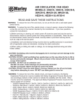
273 Branchport Avenue
Long Branch, NJ 07740
(8 0 0 ) 6 3 1 -2 1 4 8
www.wheelockinc.com
Thank you for using our products.
INSTALLATION INSTRUCTIONS
MODEL PS-12/24-6
POWERPATH
Use this product according to this instruction manual. Please keep this instruction manual for future reference.
TABLE OF CONTENTS
Page
1. POWERPATH OPERATION ......................................................................................................................................... ...2
1.1. FEATURES .................................................................................................................................................................. 3
1.2. GENERAL SPECIFICATIONS ................................................................................................................................. 3
1.3. TERMINOLOGY ........................................................................................................................................................ 3
1.4. POWER BOARD ......................................................................................................................................................... 4
1.5. CONTROL BOARD .................................................................................................................................................... 5
1.6. LED STATUS INDICATION AND TROUBLE INDICATIONS ........................................................................... 6
1.7. BATTERY MAINTENANCE..................................................................................................................................... 7
2. POWERPATH INSTALLATION ..................................................................................................................................... 7
2.1. UNPACKING ............................................................................................................................................................... 7
2.2. MOUNTING ................................................................................................................................................................ 8
3. WIRING INSTRUCTION ................................................................................................................................................. 9
3.1. CLASS B, STYLE Y HOOK-UP ............................................................................................................................... 9
3.2. CLASS A, STYLE Z HOOK-UP .............................................................................................................................. 11
3.3. WIRE ROUTING ...................................................................................................................................................... 12
4. POWERPATH APPLICATIONS .................................................................................................................................... 13
5. UL LISTED NOTIFICATION APPLIANCES ............................................................................................................. 16
TABLE OF FIGURES
FIGURE 1: TYPICAL CAPABILITIES OF THE POWERPATH ................................................................................... 2
FIGURE 2: COMPONENT LOCATION FOR POWER BOARD .................................................................................. 4
FIGURE 3: LOCATION OF INPUT AND OUTPUT TERMINALS ON CONTROL BOARD ................................... 5
FIGURE 4: BACKBOX MOUNTING DIMENSIONS ...................................................................................................... 7
FIGURE 5: SM/DSM SINGLE LINE DIAGRAM WITH POWER BOOSTER ............................................................ 8
FIGURE 6: CLASS B, Y, W HOOK-UP DIAGRAM ........................................................................................................ 9
FIGURE 7: CLASS B, Y, W FOR PARALLEL HOOK-UP DIAGRAM ........................................................................ 9
FIGURE 8: CLASS A, Y, Z HOOK-UP DIAGRAM ....................................................................................................... 10
FIGURE 9: WIRE ROUTING ........................................................................................................................................... 11
FIGURE 10: FOUR CLASS B NOTIFICATION CIRCUITS WITH AUDIBLE STROBE......................................... 13
FIGURE 11: FOUR CLASS B NOTIFICATION CIRCUITS WITHOUT AUDIBLE STROBE ................................ 14
FIGURE 12: DUAL CLASS A, X, Z HOOK-UP DIAGRAM .......................................................................................... 14
FIGURE 13: FOUR CLASS B NOTIFICATION CIRCUITS WITH SM MODULES ................................................. 15
POWERPATH - PS-12/24-6
P8 3 4 3 8 B
Sheet 1 of 18
NOTE: All CAUTIONS and WARNINGS are identified by the symbol
. All warnings are printed in bold capital letters.
WARNING: READ THESE INSRUCTIONS CAREFULLY. FAILURE TO COMPLY WITH ANY OF THE
FOLLOWING INSTRUCTIONS, CAUTIONS AND WARNINGS COULD RESULT IN IMPROPER APPLICATION
AND/OR OPERATION OF THESE PRODUCTS IN AN EMERGENCY SITUATION, WHICH COULD RESULT IN
PROPERTY DAMAGE AND SERIOUS INJURY OR DEATH TO YOU AND/OR OTHERS.
1. POWERPATH Operation
The POWERPATH is a 6 amp 12/24 VDC Power Supply/Charger used for supervision and expanded power driving capability of up
to four Notification Appliance Circuits (NAC). Total current of 6 amps, can be divided between the four outputs for applying power
to Notification Appliances. Each output is rated at 2 amps. A maximum 4 amp output is achieved by paralleling 2 outputs.
The POWERPATH under non-alarmed condition, provides independent loop supervision for CLASS A, STYLE Z and/or CLASS B,
STYLE Y FACP fire circuits (NAC’s).
Under an alarm condition, it provides power for driving the notification appliances connected to its outputs.
The unit is extremely versatile. Two FACP NAC’s can be connected to its inputs. These inputs can then be directed to control
supervision and power delivery to any combination of four outputs.
Since the outputs are isolated from ground and will not be affected by a single ground fault, the POWERPATH does not require a
ground fault detection circuit.
Figure 1: Typical Capabilities Of The Powerpath
POWERPATH - PS-12/24-6
P8 3 4 3 8 B
Sheet 2 of 18
1.1. FEATURES
This sub-paragraph describes the operating characteristics of the POWERPATH Power Supply/Charger. Included is information
about the following POWERPATH panel features:
•
U.L. Listed 864: Control Units for Fire-Protective Signaling Systems.
•
Input and Output operation: 12 or 24 VDC. Outputs are Power Limited.
•
Opto-Isolated Inputs.
•
AC Trouble Indicator: 1 Form C or 1KΩ resistor in series with contacts (jumper selectable).
•
Battery Trouble Indicator: : 1 Form C or 1KΩ resistor in series with contacts (jumper selectable).
•
EOL: End of Line resistor, 2.2KΩ (output).
•
Each output is limited to 2 amps with a resettable positive temperature coeffiecent (PTC) current protection.
•
Power Supply is protected with short circuit protection & thermal shutdown.
•
Output LED’s indicate Alarm and Loop Fault condition on corresponding outputs.
1.2. GENERAL SPECIFICATIONS
AC Input:
115 VAC / 60 Hz / 2.15 amps.
Output:
12/24 VDC at 2 amps per output.
Total loop output currents = 6 amps, available at outputs under Alarm condition.
Battery:
12 or 24 Volts (two 12 Volts in series), 12 Amp-Hour.
Standby time:
24 hours with up to 5 minutes at 6 Amps of Alarm, or 60 hours with up to 5 minutes at 6 Amps of Alarm.
Standby current:
62 mA.
INPUT1, INPUT2:
9 to 30 VDC / 2 to 5 mA.
Maximum loop resistance: 100Ω (ohms), using EOL = 2200Ω.
1.3. TERMINOLOGY
The following nomenclature are commonly used industry equivalent terms and are used throughout this manual:
CLASS A = STYLE Z
CLASS B = STYLE Y
FACP = Fire Alarm Control Panel
EOLR = End-of-Line Resistor
NAC = Notification Appliance Circuit
NOTE: Bureau of Fire Prevention, City of Chicago Requirement:
The electrical supply from the Ryan box shall be dedicated for both the power booster and the FACP if the booster is connected to the
latter.
POWERPATH - PS-12/24-6
P8 3 4 3 8 B
Sheet 3 of 18
1.4. POWER BOARD
The POWERPATH is comprised of a Control Board and a Power Supply.
The Power Supply includes transformers, batteries and a Power Board. The Power Board rectifies 28 VAC to charge and to maintain
the charge of the standby batteries. The regulated DC and/or the batteries supply 6 Amps to power the NAC. The Power Board will
supply either 12 or 24 VDC depending upon the setting of SW1, SW2 and the battery installed. An LED (Green) indicates that AC
power is present. An LED (Red) indicates that DC voltage is present. The transformer secondaries are connected in parallel to the AC
terminals of the Power Board. The batteries are connected to the +and- BAT terminals of the Power Board. (2 12V batteries in series
for 24V) The ouput of the Power Board +and- DC is connected to the Control Board +and- DC terminals. It is necessary to observe
polarity.
Figure 2:
Component Location
Power Board
POWER BOARD TERMINAL DESCRIPTION AND RATINGS:
AC:
+BAT-:
+DC-:
BAT FAIL:
AC FAIL:
28 VAC Transformer Secondary. Non Power Limited Wiring.
24 VDC or 12 VDC Battery (Observe Polarity). Non Power Limited Wiring.
24 VDC or 12 VDC to CONTROL BOARD. (Observe Polarity).
“C NC NO”: Battery Supervision.
“C NC NO”: AC Supervision.
POWERPATH - PS-12/24-6
P8 3 4 3 8 B
Sheet 4 of 18
POWER BOARD SWITCH SETTINGS:
Output 12V: SW1 = closed, SW2 = open
Output 24V: SW1 = open, SW2 = closed
POWER BOARD WIRING HOOK-UP:
115VAC/60Hz main power shall be connected to flying leads (White/Black/Green) of the transformer primary in the transformer
compartment. The transformer secondary (Green/Yellow) shall be connected to “AC”. The +and- DC terminals should be connected
to Control Board terminals +and- DC, observing polarity.
Batteries should be connected to the terminals marked +and- BAT, observing polarity. Use 12 Volt or 24 Volt batteries corresponding
respectively to desired voltage settings for loop power as set by switches SW1 and SW2 on the POWER BOARD.
1.5. CONTROL BOARD
The Control Board inputs, INP1 and/or INP2, connect to the NAC of the FACP.
If the POWERPATH is at the end of the FACP NAC, then an FACP EOLR shall also be connected to the Control Board input
terminals.
INP1 or INP2 can be selected to drive any of the four Outputs (OUT1 thru OUT4) by the setting of corresponding SW1 thru SW4.
During the normal NON-ALARM state, no LED is illuminated on the Control Board. The INP1 and/or INP2 (Green) LED’s are
illuminated by an ALARM signal input.
The OUT1 thru OUT4 (Red) LED’s are illuminated when an ALARM signal is present or a Fault is detected on the corresponding
Output.
SW5 and SW6 are used to select between Class B and Class A Outputs for OUT1, OUT3, and OUT2, OUT4.
Figure 3:
Location of input and output terminals
Control Board
POWERPATH - PS-12/24-6
P8 3 4 3 8 B
Sheet 5 of 18
CONTROL BOARD TERMINAL DESCRIPTION AND RATINGS:
+INP1-:(1) Connects to FACP Output 1; 9 to 30 VDC
+INP2-:
Connects to FACP Output 2; 9 to 30 VDC
-OUT1+:
-OUT2+:
-OUT3+:
-OUT4+:
Signal Device OUTPUT1; 12 or 24 VDC, up to 2 Amps
Signal Device OUTPUT2; 12 or 24 VDC, up to 2 Amps
Signal Device OUTPUT3; 12 or 24 VDC, up to 2 Amps
Signal Device OUTPUT4; 12 or 24 VDC, up to 2 Amps
Maximum total load shall not exceed 6 Amps.
Note: In the event of a loop overload, disconnect loop for about (2) minutes. This allows the overload protection device time to reset.
Correct the overload problem and reconnect.
“INP1” “C NC NO” and “INP2” “C NC NO”(2): Optional dry contact connection to FACP panel (see note 2).
EOLR (End of Line resistor) is a 2200Ω, 1W resistor, with body leads sufficiently long to connect across the terminals of the last
Notification Appliance in the alarm loop. (4) 2200 Ω (ohms), 1 Watt resistors are included with the unit.
Notes:
(1). Polarities on Control Board are shown to correspond with Output polarity under alarm conditions.
Under non-alarm conditions, output polarities are reversed.
(2). The “NC” and “C” terminals can be used in series with the FACP NAC.
In the event of a NAC trouble condition on the POWERPATH output, this contact will open the FACP panel NAC, thus
triggering a Trouble to the FACP panel output.
In event of an alarm, this relay is overridden so that the FACP NAC is powered as usual.
CONTROL BOARD SWITCHES: SW1 THROUGH SW4 SETTINGS:
Input to Output control is determined by switches SW1 thru SW4 for Outputs OUT1 thru OUT4, respectively, as follows, under alarm
conditions:
INP1 (connected to FACP NAC) will deliver power to any OUTPUT (OUT1 thru OUT4) where the corresponding switch
(SW1 thru SW4) is set in the OFF Position (open).
INP2 (connected to FACP NAC) will deliver power to any OUTPUT (OUT1 thru OUT4) where the corresponding switch
(SW1 thru SW4) is set in the ON position (closed).
CONTROL BOARD SWITCHES: SW5 & SW6 SETTINGS:
CLASS A, STYLE Z or CLASS B, STYLE Y operation is determined by “SW5” and “SW6”.
See CLASS A, STYLE Z and CLASS B, STYLE Y Hook-up in paragraph 3.
1.6. LED STATUS INDICATION AND TROUBLE INDICATIONS
CONTROL BOARD LED’s:
1.
2.
3.
Under normal - non-alarm and no fault conditions, all LED’s are off.
Any OUTPUT LED on while INPUT LED’s are off, indicates a NAC fault condition.
Any OUTPUT LED’s on while any INPUT LED’s are on, indicates that those NAC are activated by the
corresponding INPUT whose LED is on.
POWER BOARD LED:
AC LED is (green) ON if AC power is present.
DC LED is (red) ON if DC power is present.
POWERPATH - PS-12/24-6
P8 3 4 3 8 B
Sheet 6 of 18
POWER BOARD TROUBLE MONITORING (AC & BATTERY CONDITION):
Both AC and BATTERY FAIL offer (1) FORM C dry contacts across AC FAIL and BAT FAIL terminal outputs. Instead of dry
contacts, you can present a low resistance (1 KΩ) across AC FAIL and BAT FAIL terminal outputs. This low resistance value can be
used to create a trouble condition on the indicating NAC. Place the AC FAIL and/or BAT FAIL terminal outputs across the
indicating NAC output, while not affecting NAC integrity to be armed in the event of a fire (to present 1 KΩ resistance: cut jumper J1
for AC FAIL terminal, J2 for BAT FAIL terminal). Refer to Figure 2 and Figure 10.
AC FAIL is indicated with a minimum (6) hour delay. Optional (5) minute delay is provided for testing purposes only.
LOW BATTERY is indicated on BATTERY FAIL terminals when 24V battery drops below 20 volts, or when 12V battery drops
below 10 volts on battery.
NO BATTERY PRESENT is indicated on BATTERY FAIL terminals within 2 minutes.
1.7. BATTERY MAINTENANCE
Battery replacement: Power Sonic (or equal) 12 or 24 volt, 12 AH.
Replace with new batteries every (4) years or, as needed if battery will no longer accept full charge.
Maximum battery charging current measured in series with positive battery terminal should not exceed 1.4 amps with battery
discharged to 10V for 12V battery or 20V for 24V battery applications.
2. POWERPATH INSTALLATION
WARNING: TO REDUCE THE RISK OF FIRE OR ELECTRIC SHOCK, DO NOT EXPOSE THIS UNIT TO RAIN
OR MOISTURE.
CAUTION: These devices are not intended for use in hazardous locations as defined by the National Electrical Code (NEC) and by
the National Fire Protection Association (NFPA).
2.1. UNPACKING
The POWERPATH was carefully checked before leaving the factory. Inspect shipping container and unit carefully for indication of
improper handling. If the unit has been damaged, make an immediate claim to the carrier.
Remove the POWERPATH from the shipping container and check that the door lock keys, door lock and battery connection wires
are inside, and that the transformers, Control Board and Power Board are mounted securely to the rear of the enclosure.
POWERPATH - PS-12/24-6
P8 3 4 3 8 B
Sheet 7 of 18
2.2. MOUNTING
Mount unit in locations that do not exceed the following temperature and humidity requirements. Temperature = 0° to 49° C and
Humidity = 10% to 85% at 30° C non-condensing.
When mounting on interior walls, use appropriate screw anchors in plaster. When mounting on concrete, especially when moisture is
expected, first attach a piece of 3/4-inch plywood to the concrete surface. Attach the POWERPATH to the plywood.
Before installing the POWERPATH, the AC input must first be wired into the building’s main electrical power. The conduit entry
can be either the top right-hand side or the right-hand side of the top. Refer to Figure 4 .
CAUTION: The POWERPATH panel shall be mounted in a location within the environmental limits specified in the latest UL
standard for indoor control panels.
Figure 4:
Backbox Mounting Dimensions
POWERPATH - PS-12/24-6
P8 3 4 3 8 B
Sheet 8 of 18
3. WIRING INSTRUCTION
•
•
CAUTION:
Use POWERPATH only on circuits with continuously applied voltage. Do not use POWERPATH on coded or interrupted
circuits in which the applied voltage is cycled on and off.
Do not connect POWERPATH to the NAC after a Sync Module. Wheelock’s DSM and SM Sync Modules may be used in
conjunction with a PowerPATH ONLY IN THE ORDER SHOWN in Fig 5. Each output can use a Sync Module to drive audible
or visual synchronized devices. Refer to Section 4.
Figure 5: SM/DSM Single Line Diagram with POWERPATH
1) POWERPATH models have in-out wiring terminals that accept two #12 to #18 Gauge (AWG) wires at
terminal. Strip leads 3/8 inches and connect to screw terminals as shown at right.
each
screw
2) Seperate all in-out wire runs on supervised circuits to assure integrity of circuit supervision as shown at right. The polarity shown
in the wiring diagrams is for operation of the signals. The polarity is reversed by the FACP during supervision.
3.1. CLASS B, STYLE Y HOOK-UP
Connect notification appliances to desired indicating output (OUT1 thru OUT4).
Terminate each loop with a 2.2KΩ EOLR (End of Line Resistor).
Connect FACP outputs (two maximum) to desired Input (INP1, INP2). Appropriate FACP EOL must be used to terminate FACP
output loop. Set corresponding switches (SW1 thru SW4) to control Input to Output flow. Set SW5 and SW6 OFF (open).
Figure 6: “Class B, Y, W” Hook-up Diagram
POWERPATH - PS-12/24-6
P8 3 4 3 8 B
Sheet 9 of 18
If greater NAC current is desired, connect two Outputs in parallel for a maximum current of 4 Amps on the paralleled NAC. The
corresponding two Switches shall be set to the same position and only one Input shall be used. (see diagram, Figure 7). Two Class B
NAC’s can be driven from one FACP NAC by selecting SW1 thru SW4 to the same position. When SW1 thru SW4 is selected to the
up position, INP1 will control OUT1 thru OUT4 . SW1 thru SW4 in the down position selects INP2 to OUT1 thru OUT4.
Total load may not exceed 6 amps for all outputs. Terminate remaining outputs with EOLR.
Figure 7: “Class B, Y, W” For parallel Hook-up Diagram
POWERPATH - PS-12/24-6
P8 3 4 3 8 B
Sheet 10 of 18
3.2. “ CLASS A, STYLE Z”
HOOK-UP
Two individual CLASS A, STYLE Z loops can be hooked-up as follows (3 Amps max. per NAC):
Loop1 starts on OUT1 to all notification appliances and terminates on OUT3.
Set switch SW6 ON (closed). No EOLR is required, NAC is terminated internally.
Loop2 starts on OUT2 to all notification appliances and terminates on OUT4.
Set switch SW5 ON (closed). No EOLR required, NAC is terminated internally.
INPUT is connected to the FACP NAC as shown in diagram. It appears as another loop signaling device to the FACP. Two FACP
loops can be used by selecting SW1 and SW3 to one input and SW2 and SW4 to second input. Select SW1, SW3 and SW2, SW4 to
OFF position for OUT1 thru OUT4 to INP1.
Note: The POWERPATH is not designed to parallel Class A outputs.
Figure 8: Class A, Y, Z Hook-up Diagram
POWERPATH - PS-12/24-6
P8 3 4 3 8 B
Sheet 11 of 18
3.3. WIRE ROUTING
To avoid induced noise (transfer of electrical energy from one wire to another), keep input wiring separated from high current output
and non-power-limited wiring. Avoid pulling one multiconductor cable for the entire system. Instead, separate high current
input/output from low current wiring. Separate power-limited from non-power-limited wiring. Non-power-limited wiring must be
enclosed in conduit.
Wiring within the cabinet should be routed around the perimeter of the cabinet. It should not cross the printed circuit board where it
could induce noise into the sensitive microelectronics or pick up unwanted RF noise from the switching power supply circuit.
Figure 9: Wire Routing
POWERPATH - PS-12/24-6
P8 3 4 3 8 B
Sheet 12 of 18
POWERPATH APPLICATIONS
The following applications illustrate the use of synchronized appliances powered by the POWERPATH. The POWERPATH can
only be used on NAC’s with continuously applied voltage. Do not use POWERPATH on coded or interrupted NAC’s in which the
applied voltage is cycled on and off. Do not connect POWERPATH to a NAC after a Sync Module . Each output of the
POWERPATH can use a Sync Module Circuit to drive audible/visual, visual, audible or synchronized appliances. Refer to Series
SM, DSM Sync Modules and audible and visual notification appliance Instruction Sheets for additional information.
•
•
CAUTION:
Use POWERPATH only on circuits with continuously applied voltage. Do not use POWERPATH on coded or interrupted
circuits in which the applied voltage is cycled on and off.
Do not connect POWERPATH to the NAC after a Sync Module. Wheelock’s DSM and SM Sync Modules may be used in
conjunction with a PowerPATH ONLY IN THE ORDER SHOWN in Fig 5. Each output can use a Sync Module to drive audible
or visual synchronized devices.
Figure 10:
Four Class B Notification Circuits with Audible Silence
for Wheelock AS Strobes
SW1 and SW2 (off) selects INP1 to OUT1 and OUT2.
SW3 and SW4 (on) selects INP2 to OUT3 and OUT4.
SW5 and SW6 (open) selects Class B for all four outputs.
OUT1 through OUT4 can be selected to either INP1 or INP2 with SW1 thru SW4. An output is selected to INP1 when the
corresponding switch is in the “OFF” position. In the “ON” position, the corresponding output is selected to INP2.
SW5 and SW6 in the open position selects Class B for all outputs. SW6 allows for Class A output from OUT1 to OUT3 and SW5
allows for Class A output from OUT2 to OUT4.
POWERPATH - PS-12/24-6
P8 3 4 3 8 B
Sheet 13 of 18
Figure 11:
Four Class B Notification Circuits without Audible Silence Feature
SW1 and SW2 (off) selects INP1 to OUT1 and OUT2
SW3 and SW4 (on) selects INP2 to OUT3 and OUT4
SW5 and SW6 (open) selects Class B for OUT1 through OUT4.
Figure 12:
Dual Class A, X, Z Hook-up Diagram without Audible Silence Feature
As shown: select INP1 to OUT1 thru OUT4 (SW1 thru SW4 off) and SW5 and SW6 closed. OUT1 forms Class A loop with OUT3
with SW6 closed. OUT2 forms Class A loop with OUT4 with SW5 closed.
Note: Each Class A NAC can not exceed 3A.
POWERPATH - PS-12/24-6
P8 3 4 3 8 B
Sheet 14 of 18
Figure 13:
Four Class B Notification Circuits with SM Modules
Two Class B from INP1 with Audio Silence
Two Class B from INP2 without Audio Silence
Note: Each loop of Notification Appliances are individually synchronized.
SW1 and SW2 (off) se;ects OUT1 and OUT2 to INP1
SW3 and SW4 (on) selects OUT3 and OUT4 to INP2
SW5 and SW6 (open) selects Class B for all four outputs
POWERPATH - PS-12/24-6
P8 3 4 3 8 B
Sheet 15 of 18
4. UL LISTED NOTIFICATION APPLIANCES
The following is a list of Wheelock UL approved Notification Appliances that can be used with the POWERPATH:
Table 1
Product
Bells
Chimes
Strobe
Chimes
Mini Horn
Audible
Horn
Audible
Strobe
Notification Horn
Notification
Strobe
Multitone
Signal
Multitone
Strobe
Multitone
Sync Strobe
AddressableMultitone
Candela (cd)
------15cd - wall
15/75cd - wall
30cd – wall
75cd – wall
110cd - wall
15cd - ceiling
30cd – ceiling
75cd – ceiling
100cd - ceiling
15cd - wall
15/75cd - wall
30cd – wall
75cd – wall
110cd - wall
15cd - ceiling
75cd – ceiling
100cd - ceiling
----15cd – wall
15/75cd – wall
30cd – wall
75cd – wall
110cd – wall
15cd – ceiling
30cd – ceiling
75cd – ceiling
100cd – ceiling
--15cd – wall
15/75cd – wall
30cd – wall
75cd – wall
110cd – wall
--15cd
15/75cd
30cd
75cd
15cd
15/75cd
---
24 VDC Models
MB-G6-24
MB-G10-24
CH70-24
CH90-24
CH70-2415W
CH70-241575W
CH70-2430W
CH70-2475W
CH70-24110W
CH70-2415C
CH70-2430C
CH70-2475C
CH70-24100C
CH90-2415W
CH90-241575W
CH90-2430W
CH90-2475W
CH90-24110W
CH90-2415C
CH90-2475C
CH90-24100C
MIZ-24
AH-24
AH-24WP
AS-2415W
AS-241575W
AS-2430W
AS-2475W
AS-24110W
AS-2415C
AS-2430C
AS-2475C
AS-24100C
NH-12/24
NS-2415W
NS-241575W
NS-2430W
NS-2475W
NS-24110W
MT-12/24
MT4-12/24
MT-24-LS
MT-24-LSM
MT-24-MS
MT-24-IS
MT-24-SL
MT-24-SLM
AMT-12/24
12VDC Models
MB-G6-12
MB-G10-12
--------------------------------------MIZ-12
AH-12
AH-12WP
AS-1215W
AS-121575W
--------------NH-12/24
NS-1215W
NS-121575W
------MT-12/24
MT4-12/24
--MT-12-LSM
--------AMT-12/24
POWERPATH - PS-12/24-6
P8 3 4 3 8 B
Sheet 16 of 18
Table 1 Continued
Product
Addressable Multitone
Strobe
Addressable Multitone
Sync Strobe
Remote Strobe
Non Sync
Remote Strobe
Retrofit Plate
Candela (cd)
15cd
15/75cd
30cd
75cd
15cd
15/75cd
15cd
15/75cd
15cd
15/75cd
Remote Strobe
(Sync/Non Sync)
Remote Strobe with
Retrofit Plate
(Sync/Non Sync)
Sync
Modules
Strobe Speakers
(Sync/Non Sync)
15cd - wall
15/75cd - wall
30cd – wall
75cd – wall
110cd - wall
15cd - ceiling
30cd – ceiling
75cd – ceiling
100cd - ceiling
15cd - wall
15/75cd - wall
30cd – wall
75cd – wall
110cd - wall
15cd - ceiling
30cd – ceiling
75cd – ceiling
100cd - ceiling
--15cd - wall
15/75cd - wall
30cd – wall
75cd – wall
110cd - wall
15cd - ceiling
30cd – ceiling
75cd – ceiling
100cd - ceiling
15cd - wall
15/75cd - wall
30cd – wall
75cd – wall
110cd - wall
15cd - ceiling
30cd – ceiling
75cd – ceiling
100cd - ceiling
24 VDC Models
12VDC Models
AMT-24-LS
AMT-24-LSM
AMT-24-MS
AMT-24-IS
AMT-24-SL
AMT-24-SLM
RS-2415W
RS-241575
AMT-12-LS
AMT-12-LSM
AMT-12-MS
------RS-1215W
RS-121575W
RSP-2415W
RSP-1215W
RSP-241575
RSP-121575W
RSS-2415W
RSS-241575W
RSS-2430W
RSS-2475W
RSS-24110W
RSS-2415C
RSS-2430C
RSS-2475C
RSS-24100C
RSSP-2415W
RSSP-241575W
RSSP-2430W
RSSP-2475W
RSSP-24110W
RSSP-2415C
RSSP-2430C
RSSP-2475C
RSSP-24100C
SM-12/24
DSM-12/24
E70-2415W
E70-241575W
E70-2430W
E70-2475W
E70-24110W
E70-2415C
E70-2430C
E70-2475C
E70-24100C
E90-2415W
E90-241575W
E90-2430W
E90-2475W
E90-24110W
E90-2415C
E90-2430C
E90-2475C
E90-24100C
RSS-1215W
RSS-121575W
--------------RSSP-1215W
RSSP-121575W
-------------------------------------------------------
POWERPATH - PS-12/24-6
P8 3 4 3 8 B
Sheet 17 of 18
ANY MATERIAL EXTRAPOLATED FROM THIS DOCUMENT OR FROM WHEELOCK MANUALS OR OTHER DOCUMENTS
DESCRIBING THE PRODUCT FOR USE IN PROMOTIONAL OR ADVERTISING CLAIMS, OR FOR ANY OTHER USE,
INCLUDING DESCRIPTION OF THE PRODUCT’S APPLICATION, OPERATION, INSTALLATION AND TESTING IS USED AT
THE SOLE RISK OF THE USER AND WHEELOCK WILL NOT HAVE ANY LIABILITY FOR SUCH USE.
Limited Warranty
Wheelock products must be used within their published specifications and must be PROPERLY specified, applied, installed, operated,
maintained and operationally tested in accordance with these instructions at the time of installation and at least twice a year or more
often and in accordance with local, state and federal codes, regulations and laws. Specification, application, installation, operation,
maintenance and testing must be performed by qualified personnel for proper operation in accordance with all of the latest National
Fire Protection Association (NFPA), Underwriters' Laboratories (UL), Underwriters' Laboratories of Canada (ULC), National
Electrical Code (NEC), Occupational Safety and Health Administration (OSHA), local, state, county, province, district, federal and
other applicable building and fire standards, guidelines, regulations, laws and codes including, but not limited to, all appendices and
amendments and the requirements of the local authority having jurisdiction (AHJ). Wheelock products when properly specified,
applied, installed, operated, maintained and operationally tested as provided above are warranted against mechanical and electrical
defects for a period of three years from date of manufacture (as determined by date code). Correction of defects by repair or
replacement shall be at Wheelock's sole discretion and shall constitute fulfillment of all obligations under this warranty. THE
FOREGOING LIMITED WARRANTY SHALL IMMEDIATELY TERMINATE IN THE EVENT ANY PART NOT FURNISHED
BY WHEELOCK IS INSTALLED IN THE PRODUCT. THE FOREGOING LIMITED WARRANTY SPECIFICALLY
EXCLUDES ANY SOFTWARE REQUIRED FOR THE OPERATION OF OR INCLUDED IN A PRODUCT. WHEELOCK
MAKES NO REPRESENTATION OR WARRANTY OF ANY OTHER KIND, EXPRESS, IMPLIED OR STATUTORY
WHETHER AS TO MERCHANTABILITY, FITNESS FOR A PARTICULAR PURPOSE OR ANY OTHER MATTER.
USERS ARE SOLELY RESPONSIBLE FOR DETERMINING WHETHER A PRODUCT IS SUITABLE FOR THE USER'S
PURPOSES, OR WHETHER IT WILL ACHIEVE THE USER'S INTENDED RESULTS. THERE IS NO WARRANTY AGAINST
DAMAGE RESULTING FROM MISAPPLICATION, IMPROPER SPECIFICATION, ABUSE, ACCIDENT OR OTHER
OPERATING CONDITIONS BEYOND WHEELOCK'S CONTROL.
SOME WHEELOCK PRODUCTS CONTAIN SOFTWARE. WITH RESPECT TO THOSE PRODUCTS, WHEELOCK DOES
NOT WARRANT THAT THE OPERATION OF THE SOFTWARE WILL BE UNINTERRUPTED OR ERROR-FREE OR THAT
THE SOFTWARE WILL MEET ANY OTHER STANDARD OF PERFORMANCE, OR THAT THE FUNCTIONS OR
PERFORMANCE OF THE SOFTWARE WILL MEET THE USER'S REQUIREMENTS. WHEELOCK SHALL NOT BE LIABLE
FOR ANY DELAYS, BREAKDOWNS, INTERRUPTIONS, LOSS, DESTRUCTION, ALTERATION, OR OTHER PROBLEMS
IN THE USE OF A PRODUCT ARISING OUT OF OR CAUSED BY THE SOFTWARE.
THE LIABILITY OF WHEELOCK ARISING OUT OF THE SUPPLYING OF A PRODUCT, OR ITS USE, WHETHER ON
WARRANTIES, NEGLIGENCE, OR OTHERWISE, SHALL NOT IN ANY CASE EXCEED THE COST OF CORRECTING
DEFECTS AS STATED IN THE LIMITED WARRANTY AND UPON EXPIRATION OF THE WARRANTY PERIOD ALL
SUCH LIABILITY SHALL TERMINATE. WHEELOCK IS NOT LIABLE FOR LABOR COSTS INCURRED IN REMOVAL,
REINSTALLATION OR REPAIR OF THE PRODUCT BY ANYONE OTHER THAN WHEELOCK OR FOR DAMAGE OF ANY
TYPE WHATSOEVER, INCLUDING BUT NOT LIMITED TO, LOSS OF PROFIT OR INCIDENTAL OR CONSEQUENTIAL
DAMAGES. THE FOREGOING SHALL CONSTITUTE THE SOLE REMEDY OF THE PURCHASER AND THE EXCLUSIVE
LIABILITY OF WHEELOCK.
IN NO CASE WILL WHEELOCK'S LIABILITY EXCEED THE PURCHASE PRICE PAID FOR A PRODUCT.
Limitation of Liability
WHEELOCK'S LIABILITY ON ANY CLAIM OF ANY KIND, INCLUDING NEGLIGENCE AND BREACH OF WARRANTY,
FOR ANY LOSS OR DAMAGE RESULTING FROM, ARISING OUT OF, OR CONNECTED WITH THIS CONTRACT, OR
FROM THE MANUFACTURE, SALE, DELIVERY, RESALE, REPAIR OR USE OF ANY PRODUCT COVERED BY THIS
ORDER SHALL BE LIMITED TO THE PRICE APPLICABLE TO THE PRODUCT OR PART THEREOF WHICH GIVES RISE
TO THE CLAIM. WHEELOCK'S LIABILITY ON ANY CLAIM OF ANY KIND SHALL CEASE IMMEDIATELY UPON THE
INSTALLATION IN THE PRODUCT OF ANY PART NOT FURNISHED BY WHEELOCK. IN NO EVENT SHALL
WHEELOCK BE LIABLE FOR ANY CLAIM OF ANY KIND UNLESS IT IS PROVEN THAT OUR PRODUCT WAS A
DIRECT CAUSE OF SUCH CLAIM. FURTHER, IN NO EVENT, INCLUDING IN THE CASE OF A CLAIM OF
NEGLIGENCE, SHALL WHEELOCK BE LIABLE FOR INCIDENTAL OR CONSEQUENTIAL DAMAGES. SOME STATES
DO NOT ALLOW THE EXCLUSION OR LIMITATION OF INCIDENTAL OR CONSEQUENTIAL DAMAGES, SO THE
PRECEDING LIMITATION MAY NOT APPLY TO ALL PURCHASERS.
11/98
POWERPATH - PS-12/24-6
P8 3 4 3 8 B
Sheet 18 of 18
ADDENDUM TO PS 12/24
RECOMMENDED WAY FOR PS-12/24-6
CONNECTION TO FIRE ALARM CONTROL PANELS
1. FOR INPUT 1 RESISTOR R17 SHOULD BE REMOVED (HOOKED UP AS ILLUSTRATED)
2. FOR INPUT 2 RESISTOR R18 SHOULD BE REMOVED, IF SAME HOOKUP AS INPUT 1 IS DESIRED (OTHERWISE DO
NOT REMOVE RESISTOR R18)
POWERPATH - PS-12/24-6
P83438_1 B
Sheet 1 of 1
EACH OUTPUT OF THE PS-12/24-6 MAY BE ASSIGNED TO EITHER INPUT. IF A “TROUBLE” OCCURS ON ANY
OUTPUT THE ASSIGNED INPUT WILL OPEN, CAUSING A “TROUBLE” INDICATION TO THE FACP.
POWERPATH - PS-12/24-6
P83438_1 B
Sheet 2 of 1
THE WIRING FROM FACP TO INPUT OF THE POWER BOOSTER AS SHOWN IN FIGURE 6, 7, 10, 11, 12 AND 13 OF THE
POWER PATH PS-12/24-6 MANUAL SHOULD BE CHANGED AS SHOWN ABOVE.
NOTE:
1. CLASS “A” CIRCUIT: RETURNED TO FACP
2. CLASS “B” CIRCUIT:
OPTIONS:
a) PLACE FACP NAC EOLR ACROSS THESE CONDUCTORS; OR
b) ATTACH ADDITIONAL PS-12/24-6 TO CIRCUIT; OR
c) ATTACH ADDITIONAL NOTIFICATION APPLIANCES
WHEREVER THE FACP NAC ENDS THE FACP NAC EOLR SHALL BE ATTACHED.
POWERPATH - PS-12/24-6
P83438_1 B
Sheet 3 of 1
ADDENDUM TO PS 12/24
RECOMMENDED WAY FOR PS-12/24-6
CONNECTION TO FIRE ALARM CONTROL PANELS
POWERPATH - PS-12/24-6
P83438_2 B
Sheet 1 of 1
POWERPATH - PS-12/24-6
P83438_2 B
Sheet 2 of 1
EACH OUTPUT OF THE PS-12/24-6 MAY BE ASSIGNED TO EITHER INPUT. IF A “TROUBLE” OCCURS ON ANY
OUTPUT THE ASSIGNED INPUT WILL OPEN, CAUSING A “TROUBLE” INDICATION TO THE FACP.
THE WIRING FROM FACP TO INPUT OF THE POWER BOOSTER AS SHOWN IN FIGURE 6, 7, 10, 11, 12 AND 13 OF THE
POWER PATH PS-12/24-6 MANUAL SHOULD BE CHANGED AS SHOWN ABOVE.
NOTE:
1. CLASS “A” CIRCUIT: RETURNED TO FACP
2. CLASS “B” CIRCUIT:
OPTIONS:
a) PLACE FACP NAC EOLR ACROSS THESE CONDUCTORS; OR
b) ATTACH ADDITIONAL PS-12/24-6 TO CIRCUIT; OR
c) ATTACH ADDITIONAL NOTIFICATION APPLIANCES
WHEREVER THE FACP NAC ENDS THE FACP NAC EOLR SHALL BE ATTACHED.
POWERPATH - PS-12/24-6
P83438_2 B
Sheet 3 of 1