1
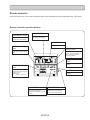
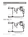
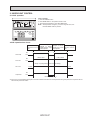
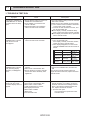
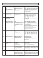
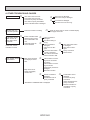
July 7, 2005
Mitsubishi Electric ‘Mr. Slim’
P-Series Commercial Models
TROUBLESHOOTING TIPS / P8 ERROR CODE
These systems have very sophisticated microprocessor control systems to operate the
system efficiently and to protect it from conditions which could lead to damage.
If the P8 Error Code appears on the wall controller this indicates a problem with the
condensing (outdoor) unit. There are several possible causes for this fault. A few are
mentioned in the literature provided by Mitsubishi, but experience has shown that
many other conditions can also result in the P8 Error Code.
1. Is there power to the outdoor unit? P-series indoor and outdoor units are
typically wired from separate sources. On cooling only units the indoor section
is 120/1/60 volt and the outdoor section is 208-230/1/60 volt. On heat pumps
both sections are 208-230/1/60 volt. The indoor unit could have power to it but
not the outdoor unit, resulting in a P8 fault.
2. Is the 2-wire 12 VDC communication link between the indoor unit and outdoor
unit intact? This wiring is polarity sensitive so if the wires are crossed, shorted
or broken this is also a problem to look for. Ensure the wires are secure in the
terminals as well. Loose wiring can cause intermittent problems.
3. There is a 208 Volt jumper for the outdoor unit control board. Verify your
power supply voltage and insure this jumper is correct for what you actually
measure at the unit with your meter. The outdoor board monitors the power.
4. The outdoor board monitors the temperature of the refrigerant leaving the
condenser coil and modulates it’s condenser fan(s) to try and maintain a 95°F
temperature. If the discharge temperature gets too high, or too low, the unit
will shut off. Verify that the pipe temperature thermistor is not open or
shorted, and that it is snug in the well attached to the refrigerant pipe.
5. Is the condenser fan operating? On the extra low ambient models (-40°F) there
is a control to disable the condenser fan(s) during very cold weather. If this
control is defective it may be preventing operation of the fan(s) in warm
weather. Ensure the condenser fan is ramping up to full speed when required.
6. Is the unit operating year-round but not a -40°F low ambient design? You can
determine this easily because the accumulator on -40°F units is heated and
insulated. Ensure the accumulator heater is functioning in the winter.
7. Is the system undercharged, or overcharged? It is a capillary tube metering
device so the refrigerant charge is critical. P-series units have an accumulator
which enables it to store enough refrigerant for up to a 100’ line set. After 100’
additional refrigerant must be weighed in based on the total 1-way lineset
length.
Please refer to the attached pages from the Service Manual for more information on
troubleshooting.
21 Grenfell Crescent, Suite 1
Ottawa, Ontario K2G 0G3
Phone: 613-723-0359
Fax: 613-226-4892, Toll Free: 1-888-279-2505
Email: [email protected]
Web: www.digelair.com
10
MICROPROCESSOR CONTROL
1. OUTLINE OF MICROPROCESSOR CONTROL
INPUT to remote controller
● OFF-ON switching.
● COOL/DRY-FAN selector switching.
● Thermostat setting.
● TIMER mode selector-switching and Timer
setting.
● HIGH-LOW fan speed switching.
● AUTO Vane selector (AIR DISCHARGE)
switching.
● TEST RUN switching.
● CHECK mode switching.
(Self diagnostic trouble shooting)
● Processes and transmits
orders.
OUTPUT to remote controller
Remote controller
● LCD indicator
SWING
TIMER OFF TIMER CLOCK AUTO AUTO
CHECK SET TEMP.
FAN
STRAT STOP SPEED
FILTER
AUTO
RETURN
CHECK MODE
TEST RUN
Non-polar, two-wire cable
maximum length 550 yards
12VDC
Indoor
unit
Remote controller board
Signal
Indoor controller board
INPUT from indoor unit
● Room temperature thermistor (RT1)
● Pipe temperature thermistor (RT2)
OUTPUT to indoor unit
● Receives orders from remote controller and temperature data from indoor unit.
● Processes orders and data.
● Controls indoor and outdoor operation.
● Self diagnostic function.
w System control operation.
w Emergency operation.
w Set by dip switch on indoor controller board.
● Transmits the power to remote controller.
Polar two-wire cable
● Compressor protection
device working
● Fan speed control.
● Crankcase heater control
ON-OFF.
● Self diagnostic function
Outdoor unit
12VDC
Independent Control of
Outdoor Unit
1
2
OC274-26
OUTPUT to outdoor unit
1 2
● Auto vane's angle setting.
● Emergency stop.
● Compressor and
outdoor fan : ONOFF
Remote controller
Once the controls are set, the same operation mode can be repeated by simply pressing the ON / OFF button.
Remote controller operation buttons
CLOCK/TIMER button
TIMER ON/OFF button
This switches between continuous
operation and the timer operation.
This sets or switches the current
time,start time and stop time.
FAN SPEED button
This sets the fan speed.
OPERATION MODE
button
ON/OFF button
Press this button to switch the cooling, electronic dry (Dehumidify),fan
modes.
This switches between the operation and stop modes each time it is
press. The lamp on this button
lights during operation.
F
AIR DISCHARGE
button
DRY COOL TIMER OFF TIMER CLOCK AUTO AUTO
FAN CHECK SET TEMP.
START STOP FAN
SPEED
SET TEMPERATURE
button
This sets the room temperature.
The temperature setting can be performed in 2˚F units.
Setting range :
Cooling 65˚F to 87˚F
This adjusts the vertical angle of the
ventilation.
MODE
TIMER ON/OFF CLOCK/TIMER FAN SPEED AIR DISCHARGE FILTER
AIR SWEEP
SET TEMP.
TIMER SET
CHECK
TEST RUN
REMOTE CONTROLLER
FILTER button
This resets the filter service indication display.
AIR SWEEP button
CHECK-TEST RUN button
This switches the horizontal fan motion
(Swing louver) ON and OFF.
(This button only operates on PK wall
models.)
Only press this button to perform an
inspection check or test operation.
Do not use it for normal operation.
OC278-5
Remote controller display
CENTRALLY
CONTROLLED display
This indicates when the unit is controlled by optional features such as
central control type remote controller.
TIMER
In this display example on the bottom left, a condition where all display lamps light is shown for
explanation purposes although this differs from
actual operation.
CLOCK display
The current time , start time and stop
time can be displayed in ten second
intervals by pressing the time switch
button. The start time or stop time is
always displayed during the timer
operation.
display
FAN SPEED display
This indicates when the continuous
operation and time operation modes
are set.
It also display the time for the timer
operation at the same time as when
it is set.
The selected fan speed is displayed.
F
F
OPERATION MODE display
DRY COOL TIMER OFF TIMER CLOCK AUTO AUTO
FAN CHECK SET TEMP.
START STOP FAN
SPEED
This indicates the operation mode.
MODE
TIMER ON/OFF CLOCK/TIMER FAN SPEED AIR DISCHARGE FILTER
AIR SWEEP
SET TEMP.
TIMER SET
display
The temperature of the return air is
displayed during operation. The display range is 47°F to 97°F. The display flashes 47°F when the actual
temperature is less than 47°F and
flashes 97°F when the actual temperature is greater than 97°F.
CHECK
TEST RUN
Operation lamp
REMOTE CONTROLLER
This lamp lights during operation,
goes off when the unit stops and
flashes when a malfunction occurs.
CHECK MODE
TEST RUN
CHECK
display
This indicates when a malfunction
has occurred in the unit which should
be checked.
display
This display lights in the check mode
or when a test operation is performed.
F display
This displays the selected setting
temperature.
display
FILTER
This lamp lights when electricity is
supplied to the unit.
display
This lamp lights when the filter needs
to be cleaned.
Caution
● Only the
display lights when the unit is stopped and power supplied to the unit.
● When power is turned ON for the first time the (CENTRAL CTRL) display appears to go off momentarily but this is not a malfunction.
● When the central control remote control unit, which is sold separately, is used the ON-OFF button,OPERATION MODE button and SET
TEMP. button do not operate.
● “NOT AVAILABLE” is displayed when the AIR DISCHARGE button are pressed.
(AIR DISCHARGE function is not provided for PC series.)
OC278-6
9
REFRIGERANT SYSTEM DIAGRAM
PU12/18/24EK
PU18/24EK1
Refrigerant pipe
(Option)
5/8
(with heat insulator)
Outdoor unit
Ball valve
Charge Check High
Pressure
plug
plug
Switch
Flexible tube
Flared connection
Outdoor coil
thermistor
TH3
Fusible
plug
Outdoor
heat
exchanger
Strainer
Accumulator
Compressor
Capillary tube
Flared connection
Refrigerant pipe
(Option)
3/8
(with heat insulator)
Capillary tube size (OD✕ ID✕ Length)
Ball valve
(with service For PU12EK ({0.126✕{0.071✕ 31.5)
port)
For PU18EK ,PU18EK1({0.126✕{0.063✕ 31.5) ✕ 2 sets
For PU24EK ,PU24EK1({0.126✕{0.063✕ 17.3) ✕ 2 sets
Flow of refrigerant
PU30/36EK , PU42EK2 , PU42EK7
PU30/36EK1 , PU42EK21
Refrigerant pipe
(Option)
3/4
(with heat insulator)
Outdoor unit
Ball valve
Charge Check High
Pressure
plug
plug
Switch
Flexible tube
Flared connection
Outdoor coil
thermistor
TH3
Fusible
plug
Outdoor
heat
exchanger
Strainer
Accumulator
Compressor
Capillary tube
Flared connection
Refrigerant pipe
(Option)
1/2
(with heat insulator)
NOTE :The symbol
indicates the diameter.
Ball valve
Capillary tube size (OD✕ ID✕ Length)
(with service For PU30EK, PU30EK1 ({0.157✕{0.079✕ 29.1) ✕ 2 sets
port)
For PU36EK, PU36EK1({0.157✕{0.079✕ 17.7) ✕ 2 sets
For PU42EK2, PU42EK21({0.157✕{0.079✕ 7.1) ✕ 2 sets
For PU42EK7({0.157✕{0.079✕ 21.7) ✕ 2 sets
Flow of refrigerant
OC247A-15
2. INDOOR UNIT CONTROL
2-1 COOL operation
SWING
<How to operate>
1 Press the ON/OFF button.
2 Press MODE button to set operation mode to Cool.
3 To set desired temperature, press SET TEMP.button.
NOTE : Set temperature changes by 2˚F in the range 65~87˚F, each
time SET TEMP. button is pressed.
F
DRY COOL TIMER OFF TIMER CLOCK AUTO AUTO
FAN
CHECK SET TEMP.
START STOP FAN
SPEED
MODE
AUTO
RETURN
TIMER ON/OFF CLOCK/TIMER FAN SPEED AIR DISCHARGE FILTER
AIR SWEEP
SET TEMP.
TIMER SET
CHECK
TEST RUN
REMOTE CONTROLLER
<COOL operation time chart>
Operation starts by
ON/OFF button
ON.
The room temperature
displayed on Remote
controller becomes equal
to set temperature.
The room temperature
displayed on Remote Operation stops by
controller rises above O N / O F F b u t t o n
OFF.
set temperature.
ON
Thermostat
OFF
LOW or HIGH
ON
Indoor fan
LOW or HIGH
OFF
Initially 10°(Changeable by remote controller setting)
CLOSE
Auto vane
CLOSE
ON
Compressor
OFF
Minimum 3 minutes W1
w1 Even if the room temperature displayed on remote controller rises above the set temperature during this period, the compressor will not
start until this period has ended.
OC274-27
(1) Compressor control
1 3-minute time delay
To prevent overload, the compressor will not start within 3 minutes after stop.
2 The compressor runs when room temperature is higher than set temperature.
The compressor stops when room temperature is equal to or lower than the set temperature.
The compressor maintains the previous state when the room temperature minus the set temperature is 0 degrees or more,
or lower than 2 degrees.
3 The compressor stops in check mode or during protective functions.
4 Coil frost prevention
To prevent indoor coil frost, the compressor will stop when the indoor coil thermistor (RT2) reads 34°F or below after the
compressor has been continuously operated for at least 16 minutes or more. When the indoor coil temperature rises to
50°F or above, the compressor will start in a 3-minute(w2) time delay.
w2 When the indoor coil temperature is 30°F or less, the compressor starts in 6 minutes.
NOTE : By turning OFF the dip switch SW1-3 on indoor controller board, the start temperature of coil frost prevention changes
from 34°F to 36°F.
5 Coil frost protection
When indoor coil temperature becomes 5°F or below,coil frost protection will proceed as follows.
<Start condition>
After the compressor has been continuously operated for 3 minutes or more,and the indoor coil temperature has been 5°F
or below for 3 minutes,the coil frost protection will start.
<Coil frost protection>
Compressor stops for 6 minutes,and then restarts.
lf the start condition is satisfied again during the first 10 minutes of compressor operation,both the indoor and outdoor units
stop,displaying a check code of“P6”on the remote controller.
<Termination conditions>
Coil frost protection is released when the start condition is not satisfied again during the allowance, or when the COOL
mode stops or changes to another mode.
(2) Indoor fan control
Indoor fan speed depends on the remote controller setting.
However, if an outdoor unit abnormality is detected, the indoor fan speed will be low, regardless of the remote controller
setting.
When the outdoor unit abnormality detection is released and the fan speed returns to the set speed, the quiet cycle control
will work.
(a) Normal control
( i ) Fan speed depends on the remote controller setting regardless of the thermostat on/off.
(ii) Fan speed will remain on low if an abnormality in outdoor unit is detected. (5 minutes)
5 minutes
SET
5 minutes
SET
low
low
OFF
NOTE 1 : Fan stops immediately if the unit stops or the check mode is started.
OC274-28
1 Start-up of outdoor unit abnormality detection.
2 Release of outdoor unit abnormality detection.
3 Unit stop due to outdoor unit abnormality
with P8 indication.
(3) Auto vane control
Auto vane position is set to 10 degrees airflow at the start-up of COOL operation. It can then be changed by the remote
controller.
(a) Vane position set mode & swing mode.
(!) Every time AIR DISCHARGE button is pressed, setting will be change.
(@) Airflow direction can be changed with AIR DISCHARGED button.
1 Fan speed : LOW
10°
60°
70°
SWING
PK12FK3 does not provide
SWING function.
2 Fan speed : HIGH
10°
30°
60°
70°
SWING
PK12FK3 does not provide
SWING function.
<AUTO RETURN>
When discharge 60° or 70° continues for 1 hour with the fan speed at LOW, the discharge direction turns to the horizontal
discharge automatically.
After that, 60° or 70° is available by setting with the remote controller, and it continues for 1 hour.
If the discharge direction changes from 60° or 70°, the direction returns to the horizontal discharge when 1 hour has
passed since the discharge 60° started.
If the discharge direction changes from 60° (or 70°) to the horizontal discharge, the 1-hour timer to return the horizontal
discharge is cancelled.
<Remote controller display>
1 10°
2 30° downward
3 60° downward
4 70° downward
5 SWING
PK12FK3 does not provide
SWING function.
Changes by pressing the AIR DISCHARGE button.
OC274-29
(4) Detecting abnormalities in the outdoor unit
After the compressor has been continuously operated for 3 minutes, if the difference between the indoor coil temperature
and room temperature is out of RANGE C for 1 minute, the indoor fan speed will turn to low. Five minutes later, if the difference is still out of
RANGE C,the outdoor unit is functioning abnormally. Thus, the compressor stops and check code “P8” appears on remote
controller.
RANGE A : Pipe temperature is more than 9 degrees above room temperature.
RANGE B : Pipe temperature is within 9 degrees either way of room temperature.
RANGE C : Pipe temperature is more than 9 degrees below room temperature.
Pipe temperature
minus room temperature
(degree)
+9
0
-9
RANGE A
RANGE B
RANGE C
OC274-30
11
TROUBLESHOOTING
1. TROUBLE IN TEST RUN
Symptom
Cause
Check points
The display “CENTRALLY
CONTROLLED” on remote
controller does not disappear.
1) Wrong address setting of remote controller/indoor controller board.
2) Timer adapter is connected to the
remote controller.
3) Signal transmission error between
indoor unit and remote controller.
1) Check the address setting of remote controller
and indoor controller.
2) Make sure the timer adapter is used correctly.
3) 1 Turn another remote controller’s DIP SW177 ON to make it sub controller.
2 Connect the sub controller to the unit, and
turn circuit breaker ON.
● If the display “centrally controlled” disappears, replace the original remote controller.
● If the display remains the same, replace the
indoor controller board.
When remote controller
POWER button is turned
ON, the check code
“E0”appears.
1) Signal transmission error between
indoor unit and remote controller
1) 1 Connect a sub remote controller.
2 Turn circuit breaker ON.
If the display “centrally controlled” remains,
replace the indoor controller board.
3 If the display disappears, turn the remote
controller POWER button ON and check as
follows.
Remote controller Sub remote controller
Malfunction
Malfunction of
1 Operating Display E0 Display
indoor Unit
of
2 Operating Display Operating Display Malfunction
Remote controller
Malfunction of
indoor Unit and
Remote Controller
3 No Display
E0 Display
4 No Display
of
Operating Display Malfunction
Remote controller
When remote controller
POWER button is turned
ON, operating display
appears, but disappears
soon.
1) Short circuit of indoor/outdoor connecting wire
2) Short circuit of transmission wire.
3) Wrong operation of remote controller
due to noise wave emitted by other
appliances.
1), 2) Check the wire
3) Turn the circuit breaker OFF, and then turn
ON.
If the remote controller remains abnormal,
despite the above measures, replace the indoor
controller board.
Despite turning POWER
button ON, the remote
controller display does not
appear.
1) Damaged remote controller.
2) Short circuit of transmission wire.
3) Bad contact of indoor CN40.
4) CN40 is attached to a sub unit.
5) Damaged power board.
6) Bad contact of CN2D.
7) Blown fuse.
8) Circuit breaker OFF.
1) Measure the voltage between terminals of
remote controller. If no voltage, remove the
terminals and measure the voltage between
wires. If the voltage is between 6VDC and
12V, replace the remote controller.
2) ~ 8) Check each point.
If it is not defective, replace the indoor
controller board.
OC274-38
2. SELF DIAGNOSTIC FUNCTION WITH REMOTE CONTROLLER
(WIRED REMOTE CONTROLLER)
2-1 When malfunction occurs during operation
When a malfunction occurs, the indoor and outdoor units stop and the malfunction is displayed on the LCD of the remote
controller.
(1) ON the set temperature display part, “CHECK” appears, and the unit CHECK mode
address and the check code are displayed alternately at one-second
intervals. (Check mode)
Example
Check
code
Unit
address
MODE
TIMER ON/OFF CLOCK/TIMER FAN SPEED AIR DISCHARGE FILTER
AIR SWEEP CHECK
(2) When one remote controller controls several units in the group control, the LCD shows the unit address and check code of the first malfunctioning unit.
(3) To cancel the check mode, press the ON/OFF button. In remote
ON/OFF control, press the remote ON/OFF switch. In centralised
control, turn OFF the ON/OFF button of centralised controller.
SET TEMP.
TIMER SET
TEST RUN
REMOTE CONTROLLER
Check button
NOTE: The latest check code is memorised, even if the check mode is cancelled by the way mentioned above. It takes
60 seconds maximum to display the memorised check code.
2-2 How to use the self diagnostic function for service
A. For normal control with one unit and one remote controller
(1) Pressing the CHECK button on the remote controller twice starts the self diagnostic function.
(2) During the self diagnostic function, “CHECK MODE” appears at two positions on the remote controller display. Then, at
least 10 seconds later, the unit address and the check code is alternately displayed at one-second intervals.
(3) Check and repair the unit according to the check code. (Refer to the next page.)
B. For group control using one remote controller
(1) Pressing the CHECK button on the remote controller twice starts the self diagnostic function.
(2) Press the
SET TEMP. button or
SET TEMP. button on the remote controller to advance or go back to the
unit address. Each time
SET TEMP. button is pressed, the unit address advances by one. Each time
SET
TEMP. button is pressed, the unit address goes back by one.
The check code and the unit address, appear alternately.
(3) The check code “U8” means no malfunction has occurred since installation.
The check code “E0” means the following conditions:
● The unit address displayed on the remote controller does not apply to any unit.
● power is not supplied to the unit.
● Signal transmitting/receiving circuit is abnormal.
(4) Check and repair the unit according to the check code. (Refer to the next page.)
OC274-39
Check
Diagnosis of malfunction
Cause
Check points
code
E0
Signal transmitting/receiving During individual unit control
1) Check the transmission wire.
error
1) Bad contact of transmission
2) Check with another remote controller. If “E0” is
(Indoor controller does not
wire
still indicated, replace the indoor controller
respond to remote controller 2) Signal transmitting/receiving cirboard.
signal.)
cuit is abnormal.
If other check code appears. replace the original remote controller.
1) Check the thermistor.
2) Measure the resistance of the thermistor.
Normal resistance should be as follows.
32°F····15kΩ
86°F·····4.3kΩ
50°F······9.6kΩ 104°F ···3.0kΩ
68°F······6.3kΩ
If the resistance is normal, replace the indoor
controller board.
P1
Abnormality of room temper- 1) Bad contact of thermistor
2) Damaged thermistor
ature thermistor (RT1)
P2
Abnormality of indoor coil
thermistor (RT2)
P3
Signal transmission error
(Remote controller does not
respond to indoor controller
signal.)
1) Check the transmission wire.
1) Bad contact of transmission
2) Check with another remote controller.
wire
If “P3” is still indicated, replace the indoor
2) Signal transmitting/receiving cirboard.
cuit is abnormal.
If other check code appears, replace the origi3) Wrong operation due to noise
nal remote controller.
wave emitted by other appli3) Short-circuit between 1 and 2 of CN40 and
ances
attach CN40 to the following units.
● Second unit in twin control
● Second and third units in triple control
● Sub units in group control
P4
Abnormality of drain sensor
1) Bad contact of transmission
wire
2) Damaged thermistor
1) Check the connector.
2) Measure the resistance of the thermistor 1 - 3.
32°F ···6kΩ
59°F ···3.2kΩ 86°F ···1.8kΩ
41°F ···4.8kΩ 68°F ···2.6kΩ 95°F ···1.5kΩ
50°F ···3.9kΩ 77°F ···2.2kΩ 104°F 1.3kΩ
If the resistance is normal, replace the indoor
controller board.
P5
Malfunction of drain pump
1) Malfunction of drain pump
2) Damaged drain sensor
1) Check the drain pump.
2) Check the drain sensor.
(Check the drop of water is on.)
If the resistance is normal, replace the indoor
controller board.
P6
Freezing protection/
overheating protection
is working.
1) Short cycle of air cycle
2) Dirty air filter
3) Damaged fan
4) Abnormal refrigerant
1)
2)
3)
4)
P7
System error
1) Wrong address-setting
1)
2) Signal transmitting/receiving cir- 2)
cuit of remote controller is
abnormal.
3) Wrong SW6-setting
3)
Check the address-setting.
Check with another remote controller. If check
code other than “P7” appears, replace the original remote controller.
Check SW6 setting.
P8
Abnormality in outdoor unit
1) Wrong wiring of indoor/outdoor
connecting wire
2) Reversed phase
3) Protection device is working
4) Damaged outdoor coil thermistor
1)
2)
3)
4)
Check the indoor/outdoor connecting wire.
Change the connection of electric wiring.
Check the protection device.
Measure the resistance of the outdoor coil thermistor. If the resistance is normal, replace the
outdoor controller board.
OC274-40
Clear obstructions from the air cycle.
Clean the air filter
Check the fan.
Check the refrigerant temperature.
4. OTHER TROUBLES AND CAUSES
vanes do not work.
t
Unit stops after 5 to
20 seconds operation
Air discharge display
is OFF and air discharge button does
not operate.
Protection function is working.
t
In this case, remote
controller is normal.
Power ON/OFF button
is not available.
Vane motor does not work.
Limit switch does not work.
Connector is poorly connected.
Vane motor is poorly assembled.
Indoor controller board is damaged.
t
Indoor controller board
deems the auto vanes
are not attached to the
unit.
Horizontal angle can
not be detected.
Beep sound is heard,
but display is turned
OFF.
Beep sound is not
heard, and display
remains OFF.
t
t
t
t
t
t
t
Vane motor is damaged.
Vane motor relay is damaged.
Limit switch is damaged.
The size of the cam is wrong.
Refer to check code on remote controller display.
See page OC274-40.
Indoor controller is
damaged.
Dip switch setting is
wrong.
Indoor controller is
damaged.
Vane motor is damaged.
Vane motor limit switch
is poorly connected.
Auto vane is wired after
power is turned to ON.
t
t
Vane motor limit switch
is damaged.
Vane motor is damaged.
Poorly connected
Disconnected
Indoor/outdoor connecting wire is connected
incorrectly.
Indoor/outdoor connecting wire shorts.
Compressor protector is
damaged.
Defroster is broken.
Remote controller is
damaged.
Transmission wire is
poorly connected
“CENTRALLY CONTROLLED” is displayed.
OC274-42
t
Transmission wire is
damaged.
Connector is poorly
connected.
Indoor terminal block is
poorly connected.
Remote controller terminal block is poorly
connected.
PK MODELS: WALL MOUNTED INDOOR UNITS
5. HOW TO CHECK THE PARTS
Parts name
Check points
Room temperature
thermistor
(RT1)
Pipe temperature
thermistor
(RT2)
Disconnect the connector, then measure the resistance using a tester.
(Surrounding temperature 50°F to 86°F)
Normal
4.3k' to 9.6k'
Abnormal
Open or short
Measure the resistance between the terminals using a tester.
(Surrounding temperature 68°F)
Fan motor (MF)
Relay connector
1
Red
5
Motor terminal
or
Relay connector
1
3 White
Black
3
Red-Black
White-Black
5
Protector
Red
M
Brown-Yellow
Brown-Blue
Red-Orange
Red-Pink
Blue
Brown
Pink
Yellow
Abnormal
30,36FK3
22.0'i10%
30.7'i10%
Open or short
Measure the resistance between the terminals using a tester.
(Surrounding temperature 68°F to 86°F)
Orange
Connector
12FK3
34.81'i10%
40.84'i10%
Normal
PK
18,24FK3
33.1'i10%
30.8'i10%
Opening and closing temperature of protector.
Open: 266i41°F (Fan motor OFF)
Close: 176i68°F (Fan motor ON)
Vane motor (MV)
4
5
2
(Refer to the thermistor)
3 6 1
Normal
Abnormal
186 to 214'
Open or short
<Thermistor Characteristic graph>
< Thermistor for lower temperature >
50
Thermistor for
lower temperature
Room temperature thermistor(RT1)
Pipe temperature thermistor(RT2)
Resistance (K")
40
Thermistor R0=15k' ± 3%
Fixed number of B=3480k' ± 2%
Rt=15exp { 3480(
32°F
50°F
68°F
77°F
86°F
104°F
1
273+t
1 )}
273
15k'
9.6k'
6.3k'
5.4k'
4.3k'
3.0k'
30
20
10
0
OC274-43
-4
14
32 50 68 86 104 122
Temperature (°F)
PL MODELS: CEILING CASSETTE INDOOR UNITS
4. How to check the parts PL12AK/PL18AK/PL24AK/PL30AK/PL36AK/PL42AK
Parts name
Check points
Room temperature
thermistor
(RT1)
Disconnect the connector then measure the resistance using a tester.
(Surrounding temperature 50-F~86-F)
Liquid pipe
thermistor
(RT2)
Vane motor
Normal
Abnormal
4.3k"~9.6k"
Open or short
(Refer to the thermistor)
Measure the resistance between the terminals using a tester.
(Surrounding temperature 68-F~86-F)
White 4
Connector
M
Orange 2
Red Ñ Blue
Red 1
5
3
Yellow
Blue
Normal
Abnormal
300"
Open or short
Red Ñ Yellow
Fan motor
Red Ñ Orange
Red Ñ White
Measure the resistance between the terminals using a tester.
Relay connector
1
Red
2 White
3 Black
1
2
3
Normal
PL
Motor terminal
or
Relay connector
12/18AK
Red-Black
21.7"
8.5"
White-Black
26.5"
12.2"
24/36/42AK
Protector
Drain
pump
Measure the resistance between the terminals using a tester.
(Surrounding temperature 68-F~86-F)
Yellow
1
Normal
Abnormal
2
101"
Open or short
Yellow
Drain sensor
Measure the resistance between the terminals using a tester.
(Surrounding temperature 50-F~86-F)
1
2
3
Normal
Abnormal
0.6k"~6.0k"
Open or short
OC246-37
Abnormal
(Refer to the thermistor)
Open or short
PC MODELS: CEILING SUSPENDED INDOOR UNITS
5. How to check the parts
Parts name
Check points
Room temperature
thermistor
(RT1)
Liquid pipe
thermistor
Disconnect the connector then measure the resistance using a tester.
(Ambient temperature 50°F to 86°F)
(RT2)
Vane motor (MV)
Pink
Normal
Abnormal
4.3k" to 9.6k"
Open or short
(Refer to the thermistor)
Measure the resistance between the terminals using a tester.
(Ambient temperature 77°F)
4
Normal
M
Red 5
Abnormal
PC24/30/36/42GK
Connector
Orange 2
Red — Yellow
1
Blue
3
Red — Blue
Yellow
150"
Red — Orange
Open or short
Red — Pink
Fan motor (MF)
Measure the resistance between the terminals using a tester.
Relay connector
1
Red
2 White
3 Black
Normal
Motor terminal
or
Relay connector
24GK
30,36,42GK
2
Red-Black
12.2"
7.6"
3
White-Black
16.7"
8.3"
1
Abnormal
PC
Open or short
Opening and closing temperatuer of protector.
Open: 266i41°F (Fan motor OFF)
Close: 176i68°F (Fan motor ON)
Protector
<Thermistor Characteristic graph>
Thermistor for
lower temperature
< Thermistor for lower temperature >
Room temperature thermistor(RT1)
Liquid pipe thermistor(RT2)
50
Thermistor R0=15k' ± 3%
Fixed number of B=3480k' ± 2%
Rt=15exp { 3480(
32°F
50°F
68°F
77°F
86°F
104°F
1
273+{(t-32)/1.8}
1 )}
273
15k'
9.6k'
6.3k'
5.4k'
4.3k'
3.0k'
Resistance (K")
40
30
20
10
0
OC278-39
-4
14
32 50 68 86
Temperature (°F)
104 122
10
MICROPROCESSOR CONTROL
OUTDOOR MICROPROCESSOR CONTROL
1. Protection function
(1) As soon as a reversed phase, an open phase, or a P. C. board trouble is sensed, the operation stops and the check code
is displayed by LED on the outdoor controller board.
(2) When a protection function such as high pressure switch and overcurrent relay works for the first time, the operation stops
and restarts after 3-minute time delay mode. When the second protection function works, the operation stops and the check
code is displayed by LED. This condition continues until the outdoor unit receives OFF command from the indoor controller
board. Check code indication continues until the outdoor unit receives the ON command from the indoor controller board.
(3) The second protection function is not necessary to be the same as the first one. The content of the second protection function is loaded in the memory, which is cleared when SW1 turns to ON or the next check mode starts.
2. Control by outdoor coil thermistor
(1) Unit control
Outdoor coil temperature range for control is from -40-F to 194-F. When reading 194-F or above, the outdoor coil thermistor is regarded as short-circuit. When reading -40-F or below, the outdoor coil thermistor is regarded as open-circuit.
An open circuit is not sensed for the first 7 min. after the compressor start up, but is sensed during defrosting operation or
for the first 10 seconds after the compressor start-up.
(2) Target temperature of outdoor coil temperature
Fan rotational frequency is controlled so that the outdoor coil temperature keeps 95-F ± 4-F.
3. Unit operation control
The compressor receives signal from the indoor unit and make the outdoor unit start or stop.
4. Fan control
Fan rotational frequency is phase-controlled so that the outdoor coil temperature reaches the target temperature. This control
enables cooling operation even if the outdoor temperature is low. Fan rotational frequency is adjusted by fan output. Fan output
is divided into 256 steps from 0 to 255 and is controlled every 30 seconds.
(1) Initial setting
A. When power is turned to on, or when the compressor restarts after interval of 30 minutes or more :
● If the outdoor coil thermistor reads 46-F or above, the fan output step becomes 100.
● If the outdoor coil thermistor reads below 46-F, the fan output step becomes 200.
B. When the compressor restarts within 30 minutes after stop, the fan output step is the same as the fan output before the
compressor stops.
C. When the operation mode is changed within 30 minutes after the compressor stop, the fan output step becomes 100.
D. When the operation mode is changed after the compressor interval of more than 30 minutes, the fan output step is the
same as described in A.
(2) For the first 2 minutes after the compressor start-up, the fan operates at the initial setting output, and then every other 30 seconds, the fan output is adjusted depending on the difference between the outdoor coil temperature and the target temperature. But as soon as the outdoor coil temperature becomes 122-F or above, the fan output step becomes 255.
(3) When the outdoor coil thermistor reads 122-F or above, the fan output step becomes 255.
(4) When the high pressure switch (63H1) functions, the fan output step becomes 255. After that, when the switch returns, the
fan control returns to the normal control.
5. Crankcase heater control
(1) With jumper wire J3
The crankcase heater is ON from the power is turned to on till the compressor starts, and turns to ON 1 hour after the compressor stop.
(2) Without jumper wire J3
The crankcase heater is ON from the power is turned to on till the compressor starts, and repeats ON/OFF on a 1-hour schedule.
OC247A-16
6. Fixed fan-output
While the compressor is operating and the fan output step is indicated by LED, pushing SW2 fixes the fan output of that time.
The fixed fan-output can be released when either of the following conditions is satisfied.
1 SW2 is pushed again.
2 SW3 setting is changed.
3 The compressor stops.
7. Function of switches on the outdoor controller board
SW1
: Clears the check code memory (push-button switch)
SW2
: Switches the output state indication and the check code display (push-button switch)
SW3-1and3- 2 : Switches the output state indication items (dip-switch)
For further information, please refer to page 18.
8. Operation during the power-on-reset state
(1) When the circuit breaker is turned to ON, the microprocessor enters the power-on-reset state, which continues until the
direct current for the microprocessor control reaches 12V.
Then the microprocessor starts operation in the following order.
1 Each I/O port clearance
2 Function input
Function depends on jumper wires set beforehand in the factory.
Jumper wire
Function
J1
Reversed phase sensor
J2
Not applied for series PU
J3
J4
With jumper wire
Without jumper wire
Sensed
Not sensed
Crankcase heater control
Refer to 5 (1) on page 16.
Refer to 5 (2) on page 16.
Target temperature of outdoor
coil temperature
86-F
For heat pump units
95-F
For cooling unit
3 Check for a reversed phase
4 Check for an open phase (with J1)
5 50/60Hz judgment
6 EEPROM data loading (check mode, and total time of compressor operation)
7 Coil temperature initial input
(2) If an open phase or a reversed phase is sensed, LED blinks every other second.
NOTE
❈ If power is not supplied to the transformer and the microprocessor, the microprocessor does not work and can sense neither a reversed phase nor an open phase.
❈ If a contact point of protective device such as the high pressure switch has already been opened in the power-on-reset
state, it is regarded as an open phase.
In this case, all LED are OFF.
9. 100% fan output
Fan output is fixed to 255 (100%) by shorting CN22. However, the fan stops during compressor OFF or defrosting operation.
Open circuit of CN22 enables the fan control to start.
10. Time shortening
Short circuit of CN21 shortens the time listed below.
1) Fan control period : 30 sec. ➝ 3 sec.
2) Three-minute time delay function : 3 min. ➝ 3 sec.
3) Compressor ON/OFF time for bypass valve ON/OFF : 30 min. ➝ 30 sec.
4) Compressor ON time to start other functions : x min. ➝ x sec.
OC247A-17
11
TROUBLESHOOTING
1.SERVICE DATA INDICATION BY SWITCHES ON OUTDOOR CONTROLLER BOARD
Setting dip switches SW2 and SW3 on the outdoor controller board enables LED to show the output state and check code.
Output state is shown by LED lighting, and check code by blinking.
SW1 : Turning SW1 ON clears the check code. If SW1 is turned ON while the check code is blinking , the indication changes
to output state indication.
NOTE : SW1 is usually available independent of SW3 setting. As an exception, when the check code shows a
reversed phase or an open phase during the power-on-reset state, SW1 is not available.
SW2 : SW2 is turned ON by pressing, and OFF by releasing.
When SW3-1 and SW3-2 are OFF, pressing SW2 changes indication between output state and check code
alternately.
When SW2 is turned On with SW3-1 OFF and SW3-2 ON, the compulsory defrosting starts.
SW3 : Output state indication items depend on the combination of SW3-1 ON/OFF and SW3-2 ON/OFF.
Changed alternately by pressing SW2.
Check code
Output state
Outdoor coil
temperature
(bit)
Fan output
step
(bit)
Total time of
compressor
operation(Hr)
SW3-1
OFF
OFF
OFF
ON
ON
SW3-2
OFF
OFF
ON
OFF
ON
1
1
256
2
2
512
Lighting
LED
Blinking
LD1
Reversed phase
LD2
Open phase
LD3
Outdoor coil thermistor
is abnomal.
During 63H1 function
4
4
1024
LD4
63H2 function
Compressor ON
8
8
2048
LD5
51C function
Outdoor fan ON
16
16
4096
LD6
26C function
4-way valve ON
32
32
8192
LD7
Overheat protection
Bypass valve ON
64
64
16384
LD8
Input circuit on controller
board is abnormal
Crankcase heater ON
128
128
32768
Compressor ON command from
indoor controller
Heating operation command from
indoor controller
OC247A-18
-F
212
1-1 Outdoor coil temperature
To obtain data on the outdoor coil temperature,
add the number of bits of lighting LEDs, and
see the graph to find the temperature.
(Short 38 bits)
176
140
Temperature
104
68
32
-4
-40
(Open 219 bits)
0
50
100
150
200
255
Number of bits
1-2 Fan output step
To obtain data on the fan output step, add the number of bits of lighting LEDs, and see the graph below to find the fan
rotational frequency.
2PU18/36EK , PU42EK2 , PU42EK7
PU18/36EK1 , PU42EK21
Fan rotational frequency (rpm)
Fan rotational frequency (rpm)
1PU12/24/30EK
PU24/30EK1
800
600
400
200
0
50
100
150
200
250
Fan output step (bit)
800
600
400
200
0
50
100
150
200
250
Fan output step (bit)
1-3 Total time of compressor operation
Compressor operation time is indicated in 256 hour units. To obtain the compressor operation time, add the hours of lighting LEDs. During the compressor operation time indication, SW2 is not available.
1-4 Check code indication
● When a protection function works for the first time during operation, the operation stops and restarts after the 3-minutes
time delay mode. When the protection function works again, the operation stops. (Check mode) When both SW3-1 and
SW3-2 are OFF, the check code is indicated.
● If the outdoor controller board receives the compressor ON command from the indoor controller board during check
mode the indication changes to output state indication.
● By pressing SW2 during normal operation. operation will continue.
● The latest check code is indicated.
OC247A-19
2. TROUBLESHOOTING ACCORDING TO CHECK CODE
Blinking
Diagnosis of malfunction
LED
LD1 Reversed phase
Cause
Check point
This model does not have this
function.
No need to be checked.
This model does not have this
function.
No need to be checked.
LD2
Open phase
LD3
Outdoor coil thermistor is
● Outdoor coil thermistor is
abnormal. (Open circuit or short
broken.
circuit)
● Thermistor was connected
incorrectly.
LD4
High pressure switch (63H2)
function
● 63H2 was badly connected.
● 63H2 was working.
● Check 63H2 and the outdoor fan motor.
● Check if refrigerant supply is low.
● Check if air cycle is short-cycled.
LD5
Thermal relay function
This model does not have this
function.
No need to be checked.
LD6
Thermal switch (26C) function.
● 26C was connected incorrectly.
● 26C is working.
● Check 26C.
● Check if refrigerant supply is low.
● Check if the capillary tube is clogged.
LD7
Over heat protection
● The thermistor is broken.
● Coil temperature is over
153-F.
● Measure the resistance of the thermistor.
● Check the outdoor fan motor.
● Check if air cycle is short-cycled.
LD8
Input circuit of outdoor controller board is abnormal.
● Pulse input is abnormal.
● Replace the outdoor controller board.
● Measure the resistance of the thermistor.
● Check the thermistor. If normal, replace the outdoor controller board.
3.WHEN OUTDOOR UNIT DOES NOT WORK
Cause
1) Indoor/outdoor connecting wires are poorly connected.
(Refer to next page.)
2) Power supply is poorly connected.
3) Connector or transformer is broken.
4) Fuse (6A) in the outdoor controller board is blown.
Check points
1) Check the connecting wires.
2) Check the power supply.
3) Check connector and transformers.
4) Check the fuse.
OC247A-20
4. WRONG WIRING ON SITE
4-1 Between remote controller and indoor unit
If wire is disconnected between the remote controller and the indoor unit, the POWER ON display does not appear despite
turning the power switch ON. The beep sound is not heard, either.
4-2 Phenomena due to wrong wiring between indoor and outdoor units
Wrong wiring
Indoor unit
1
Thermostat
Outdoor unit
1
2
Phenomena
OFF
The outdoor unit stops.
ON
Operation stops. 9 minutes later, the check code ¨P8¨ appears
on the remote controller display.
OFF
Operation stops.
ON
9 minutes later, the check code ¨P8¨ appears on the remote controller display.
2
Disconnect between 1 and 1 or 2 and
2.
5. HOW TO CHECK THE PARTS
PU12,18,24,30,36EK
PU18,24,30,36EK1
Parts name
OUTDOOR COIL
THERMISTOR (TH3)
FAN MOTOR(MF,1,2,3,4)
[PU12,18,24,30]
Protector
PU42EK2 PU42EK7
PU42EK21
OUTDOOR UNIT
Check points
Disconnect the connector then measure the resistance using a tester.
(Surrounding temperature 50-F~86-F)
Normal
Abnormal
4.3k"~9.6k"
Open or short
Measure the resistance between the terminals using a tester.
(Surrounding temperature 68-F)
White
Orange(Yellow)
Red(Brown)
Blue
[PU36,42]
Motor terminal
or
Relay connector
Abnormal
Normal
PU12,18 PU24,30
PU36
PU42
White – Blue
77.3"
100.2"
73.9"
61.5"
Blue – Red (Brown)
134.6"
83.8"
118.7"
79.8"
White
Orange(Yellow)
Red(Brown)
Blue
Protector
CRANKCASE
HEATER (HC)
Measure the resistance between the terminals using a tester.
Abnormal
Normal
PU12,18
PU24,30,36,42
1920"
1340"
Open or short
OC247A-21
Open or short