1
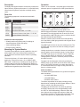
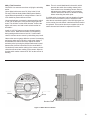
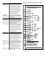
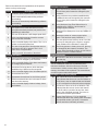
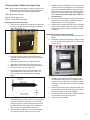
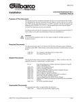
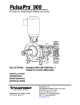
6280A System Monitor Assembly Installation & Service Manual Franklin Fueling Systems • 3760 Marsh Rd. • Madison, WI 53718 USA Tel: +1 608 838 8786 • 800 225 9787 • Fax: +1 608 838 6433 • www.franklinfueling.com Important Safety Messages Healy equipment is designed to be installed in association with volatile hydrocarbon liquids. Installing or working on this equipment means working in an environment in which these highly flammable liquids may be present. Working in such a hazardous environment presents a risk of severe injury or death if these instructions and standard industry practices are not followed. Read and follow all instructions thoroughly before installing or working on this, or any other related, equipment. Warning Warning Warning 2 Follow all applicable codes governing the installation and servicing of this product and the entire system. Always lock out and tag electrical circuit breakers while installing or servicing this equipment and any related equipment. A potentially lethal electrical shock hazard and the possibility of an explosion or fire from a spark can result if the electrical circuit breakers are accidentally turned on during installation or servicing. Follow all federal, state and local laws governing the installation of this product and its associated systems. When no other regulations apply, follow NFPA codes 30, 30A and 70 from the National Fire Protection Association. Failure to follow these codes could result in severe injury, death, serious property damage and/or environmental contamination. Always secure the work area from moving vehicles. Some of the equipment in this manual is mounted outside, so reduced visibility puts service personnel working on this equipment in danger from moving vehicles entering the work area. To help eliminate these unsafe conditions, secure the area by using a service truck to block access to the work environment, or by using any other reasonable means available to ensure the safety of service personnel. Warning The Vapor Recovery System is used to collect and monitor gasoline vapors. You may create an explosion hazard if you do not follow the requirements in this manual carefully. Warning All wiring must enter the SMCB enclosure through the designated knockouts. An explosion hazard may result if other openings are used. Contents Important Safety Messages.............................................................................................2 Description........................................................................................................................4 Parts List.................................................................................................................................. 4 Mounting the System Monitor.........................................................................................4 Operation...........................................................................................................................4 Alarm Conditions..................................................................................................................... 4 Printing Reports....................................................................................................................... 5 System Monitor Control Box (SMCB).............................................................................5 Mounting the SMBC . .............................................................................................................. 5 SMCB Wiring Instructions........................................................................................................ 6 6275 Vent Sensor Assembly............................................................................................9 Installation of the 6275 Vent Sensor Assembly........................................................................ 9 9800-1 Pressure Switch.................................................................................................12 Mounting................................................................................................................................ 12 Electrical Installation ............................................................................................................. 12 Vacuum Line Installation ....................................................................................................... 12 9800-1 Test Procedure........................................................................................................... 13 System Program.............................................................................................................14 Downloading Parameters...................................................................................................... 14 Interpreting the System Monitor Printout............................................................................... 15 Changing Paper / Ribbon Cartridge Guide ............................................................................ 17 Replacing the Printer Paper Roll.................................................................................................. 17 Replacing the Printer Ribbon Cartridge....................................................................................... 17 Monitor Maintenance Log Sheet...................................................................................18 Field Test Guide . ...........................................................................................................19 Healy 6280 Monitor Troubleshooting Guide ...............................................................20 3 Description The Healy 6280 System Monitor continuously monitors the Vapor Recovery System performance. It is used with Healy central vacuum systems, and prints out a daily activity report. Operation There is no on-off switch – the power light is illuminated whenever power is supplied to the 6280 System Monitor. Parts List The following equipment is included with the 6280A system: Part # MOTOR RUN VENT LOW RESET EXCESS POWER Description 6280 System Monitor 6275 Vent Sensor Assembly 9466 1" Check Valve 9800-1 Pressure Switch HPV1.5 Pressure Vent Valve, + 1.5" WC HPVV Pressure / Vacuum Vent Valve +3" / -8" WC SMCB System Monitor Control Box Installer-Provided equipment: • Suitably rated motor-starting relay if installing an electrically-driven VP500 vane pump • Various plumbing fittings • Electrical wiring materials Mounting the System Monitor The 6280 System Monitor must be installed in view and audio range of the Point of Sale (POS) terminal so it can be both seen and heard by the location’s operating attendant. The control unit has a 15' cord to allow for proper positioning. There will be seven, 16 to 18 AWG, 600V, NEC Class 1 conductors (in conduit) used to get the low voltage signal sources from the 6280 System Monitor to the System Monitor Control Box (SMCB) which should be located near the gasoline pump motor relays. RESET PRINT Figure 1: 6280 Controls and Indicators When there is a requirement to pump product, the MOTOR light will illuminate, indicating the vacuum pump has started. The LOW light will blink on and off for a few seconds after the MOTOR light comes on until the vacuum has reached required specifications. When the vacuum source reaches its normal operation level, the blinking LOW light goes dark and the green RUN light will illuminate. The VENT light will come on any time venting occurs. The EXCESS light only comes on when the venting is beyond specifications. Venting can be due to a number of factors, all considered normal, and do not in themselves cause a venting failure. The VENT light may go on a number of times, especially during a tanker delivery. A continuous or accumulated venting episode, 10 hours in a 24-hour period, will cause the alarm to sound. The alarm can be silenced for 4 hours by pressing the RESET button on the VENT side of the front of the control panel. The EXCESS light will go out when the problem is corrected and there is no longer venting more than 10 hours in a 24-hour period. Alarm Conditions The Model 6280 System Monitor can go into three specific alarm conditions: • NO VACUUM Failure • VACUUM Failure • EXCESS VENT Failure The failure responsible for the alarm sounding can be determined by reviewing the 6280 System Monitor “Failure History” printout. (See the next section) The alarm can be silenced for four hours by pressing the RESET button next to the red light flashing under the VENT or VACUUM headings. When the alarm has been silenced, the red lights will continue to flash until the problem is repaired. The alarm will sound again if the cause of the failure is not repaired within four hours. 4 Printing Reports Each day at midnight an automatic printout of the previous days’ activity will be printed. This will show all the previous data about run time and will show if any errors occurred that day. It does not show a history of errors. To get a history printout, press both RESET buttons on the front panel at the same time to print a 15-line summary of the last 15 failures. If there are more than 15, the oldest line is dropped off and the latest line is added. Pressing the PRINT button will get an up-to-the-minute printout of the site summary and current activity. All printouts should be saved for local authorities. The 6280 has a replaceable printer ribbon cartridge and uses standard non-thermal paper. The replacement part numbers for the paper and the ribbon are: 628028 Printer paper roll 628029 Printer ribbon cartridge System Monitor Control Box (SMCB) The SMBC serves as a junction box for the CB1 relay / CB1A relay socket and the 1005W-4 solid-state relay. It also acts as a junction box for the wiring cable supplied from the 6280 System Monitor, the 12VDC plugin power supply, field wiring from the 9800-1 Pressure Switch, field wiring from the 6275 Vent Sensor Assembly, and field wiring from the gasoline pump motor relays. 12 19 It should also be near the electrical conduits from the 9800-1 Pressure Switch and the 6275 Vent Sensor Assembly. Mount the box firmly using screws (not supplied) through the holes in the bottom of the box. The CB1 Relay, mounted in the CB1A relay socket, is connected to the power of the vacuum source and closes a contact that activates the yellow MOTOR LED light and usually the red LOW LED, on the 6280 System Monitor. The RUN light will illuminate and the LOW light goes dark when the monitor receives the signal from the 9800-1 Pressure Switch, that the proper vacuum level has been reached within the predetermined time. With an input signal from a gasoline pump motor relay, the 1005W-4 Solid State Relay senses the activation of any product pump and transfers that signal to the starting relay of whichever vacuum source is being utilized at the site. Refer to the section “Changing Paper / Ribbon Cartridge Guide”. 10 19 Mounting the SMBC Mount the SMCB near the gasoline pump motor relays and near a 110V standard electrical outlet for the 12VDC plugin power supply. Note: Keep high-voltage wiring and low-voltage wiring in separated conduit. Wires from 12VDC Supply 11 21 21 12 Wires to Switches 21 11 20 10 Brown Orange Yellow 9 Wires to 6280 System Monitor Box 20 3 5 7 Relay Inputs 21 1005W-4 Relay 1 405277901 CB1 Relay with CB1A Relay Socket 2 Black 110 Volt Supply White 17 2 9 20 8 Blue Output to Relay with Vacuum Source SMCB Figure 2: SMCB Wiring 5 SMCB Wiring Instructions These instructions cover the Healy Systems SMCB used with the Model 6280 System Monitor. Follow all caution notices and make sure all power is turned off while making connections. Make sure all power is on the same phase, including that of the gasoline pump motor relays. Note: All Class 2 wiring is being run as Class 1 and can be run together per the Article 725 of the NEC. The use of shielded, twisted pair wire (18AWG min.) is recommended for remote sensor wiring. The SMCB has some connections already made and field wiring pigtails already installed. Make sure the wiring is contained within the appropriate twist retainers. Mixing Class 1 and 2 voltages is acceptable within the SMCB only, provided the Class 2 is wired with Class 1 wire and ¼" spacing is maintained. Wire numbers refer to wiring schematics on page 7 & 8 – refer to it and the instructions below frequently to assure proper dressing. Multiple conduit openings are available. Wire Number 6 FROM Dress thru twist tie The seven wires which run to the 6280 system monitor, in the front of the store / station, should be numbered in the field to correspond to the drawing as well. Field wiring must be run in conduit to correspond to NFPA 70 and 30A and be of NEC types for Class 1, with a minimum #18 AWG, with 600 volt insulation. Install a 110 VAC non-switched outlet near the SMCB, for power to the plug-in 12 VDC power supply. The two wire (zip cord) output of this unit supplies the SMCB and is epoxied to the strain relief bushing supplied. There is a red LED epoxied into the strain relief which indicates when the 12VDC is present. The Class 1 wires are identified as red #19 for the +12 VDC and black wire #10 for the negative – do not mix the wire numbers during installation. All connections should be made using appropriately sized wire nuts. The power supply is internally fused and cannot be repaired if the leads are shorted together. The wiring should be separated and contained within the twist retainers. TO FUNCTION 1 110VAC main RED 1005W-4 black lead (1) AC hot to solid state relay 2 AC neutral RED 1005W-4 white lead (2) CB1 coil (WIRE #2) Neutral return 3 1005W-4 brown lead RED 110V hot side of submersible turbine pump relay Input signal of pump motor control relay which turns on a relay where vacuum source is located (blue wire #17) 5 1005W-4 orange lead RED Same as above #3 for second source motor Same as above. (cap if not used) 7 1005W-4 yellow lead RED Same as above #3 for third source Same as above,(#3) (cap if not used) motor 8 M3-T2 vac. motor RED Hot side of CB1 control relay coil Provides signal to turn on RUN light. 9 CB1-5 White Pigtail WHT CB1-5 white pigtail Provides signal to system monitor box to activate MOTOR light and internal timers 10 -12VDC power supply WHT Black wire from system monitor Supplies –12VDC to operate system 11 Blue wire from 6280 Monitor WHT 6275 Vent switch, common terminal Provides the signal to activate system monitor 12 Brown wire from 6280 Monitor WHT 9800-1 Vacuum switch, common terminal Provides vacuum switch signal source to system monitor 17 Blue wire from 1005W-4 relay RED Output side of 1005W-4 relay to activate vacuum source Provides output signal voltage to turn on relay for vacuum source - may be either M3 or M4 as shown on dwgs. 9200-6308-220, Sheets 1 and 2 18 M4-T2 vac. motor run control relay RED Hot side of CB1 control relay coil Provides signal to turn on RUN light 19 +12 VDC WHT Red wire from system monitor Supplies +12 VDC operate system 20 Green wire from 6280 monitor. Ground lug in center of box Common ground lug for monitor box (wire #20) all bonds 21 CB1-3 Orange Pigtail Orange wire from system monitor, signal common, connects to 98001 pressure switch, 6275 vent, switch, and terminal #3 on CB1 relay Common signal return to system monitor –– WHT 7 120 VAC 7 6 5 4 3 HEALY 9800-1 PRESS SWITCH MOUNTED W/ VAC SOURCE 12 COM 12VDC, 1.5A HEALY PLUG-IN 628021 POWER SUPPLY HEALY SYSTEM MONITOR 6280 12 19 21 BRN RED ORANGE NO SEE NOTE 3 20 GRN 21 10 BLK NC 11 BLU JBOX 9 7 1 WHT 5 1 1 2 3 1 DISPENSER SWITCH L2 L1 L2 L1 L2 L1 8 T2 T1 T2 T1 M1 7 3 11 21 COM VACUUM ON SIGNAL RELAY CB-1 8 5 2 2 NEUTRAL NO NC GRAY 3 BRN 5 ORG 7 YEL 20 2 WHT BLU 17 20 HAZARDOUS AREA NON-HAZARDOUS AREA Installation must be in accordance with NFPA70 and NFPA30A. Locate the 6280 monitor in position for convenient viewing and hearing of audible alarm by site personnel. Electrician must allow sufficient wire to pull thru J-Box to wire differential pressure switch. Wires 9 thru 15, 19, and 21 are class 2. Low voltage, DC 1005W-4 SOLID STATE RELAY 1 BLK 4. 3. 1. 2. NOTES: CAUTION ALL 120VAC WIRING MUST BE ON THE SAME PHASE. 6280A Wiring Schematic Number 1 HEALY 6275 VENT SENSOR ASSEMBLY MOUNTED ON 2” VENT PIPE 21 SMCB GAS PUMP MOTOR RELAY W/ 9000 MINI-JET 2 CB1 RELAY 8 M3 GAS PUMP MOTOR RELAY M2 GAS PUMP MOTOR RELAY SEE NOTE 3 9 COIL 17 5 3 T2 T1 120 VAC 1 1 1 3 5 BLK BLU WHT 20 10 11 9 7 BRN 19 GRN RED 21 21 NC NO SEE NOTE 3 ORANGE 12 SEE NOTE 5 NEW GAS PUMP MOTOR RELAY 1 2 3 4 5 6 7 JBOX DISPENSER SWITCH HEALY SYSTEM MONITOR 6280 12 COM 12VDC, 1.5A HEALY PLUG-IN 628021 POWER SUPPLY HEALY 9800-1 PRESS SWITCH MOUNTED W/ VAC SOURCE L1 L2 L1 L2 L1 L2 L1 L2 3 5 7 17 9 T1 T2 T1 T2 T1 T2 18 M1 GAS PUMP MOTOR RELAY M2 GAS PUMP MOTOR RELAY M3 M4 7 3 21 GAS PUMP MOTOR RELAY 18 CB1 RELAY 5 8 11 COM VACUUM ON SIGNAL RELAY CB-1 SEE NOTE 3 NC NO NEUTRAL 2 2 2 SMCB 21 20 6280A Wiring Schematic Number 2 CAUTION ALL 120VAC WIRING MUST BE ON THE SAME PHASE NOTES: 20 HAZARDOUS AREA NON-HAZARDOUS AREA 1. Installation must be in accordance with NFPA70 and NFPA30A. 2. Locate the 6280 monitor in position for convenient viewing and hearing of audible alarm by site personnel. 3. Electrician must allow sufficient wire to pull thru J-Box to wire differential pressure switch. 4. Wires 9 thru 15, 19, and 21 are class 2. Low voltage, DC 5. UL listed motor control relay for HP of vacuum source, size 1 or smaller. 2 WHT 1005W-4 SOLID STATE RELAY 1 BLK Dedicated STP for Healy 9000 MiniJet (or) VP500 vane pump ½ HP 50/60HZ 115/230VAC 7 YEL 5 ORG 3 BRN GRAY BLU 17 HEALY 6275 VENT SENSOR ASSEMBLY MOUNTED ON 2” VENT PIPE 8 6275 Vent Sensor Assembly Installation of the 6275 Vent Sensor Assembly The Healy System 6275 Vent Sensor Assembly consists of the vent sensor body assembly plus the Model 6275 Pressure Switch. In addition, a +1.5" WC pressure vent valve is mounted on top of the sensor, with the designation HPV1.5. This unit is intended for use only with the 6280 System Monitor and must be installed in parallel with the +3" / -8" WC CARB-approved pressure / vacuum vent valve P / N HPV V. Refer to Figures 5 & 6. All wiring must be done in accordance with NFPA 70 and 30A requirements. Conduits must be properly sealed for hazardous locations, both in the vent area and inside the building where the wires terminate, per NEC. If the installation is being done as a retrofit: Figure 3: 6275 Vent Sensor Assembly The 6275 Vent Sensor assembly is mounted on top of the manifolded tank vent pipes below the +1.5” WC Pressure Vent Valve (P/N HPV1.5). Two wires (16 or 18 AWG) from the SMCB exit the building through a sealed conduit. These wires must be 600 volt rated, Class 1 type insulation. They connect to the switch terminals common (COM) and normally open (NO) inside the 6275 Vent Sensor Switch. See 6280A Wiring Schematics 1 and 2 (Pages 7 & 8) for general layout and installation requirements. These wiring diagrams are part of the Healy Systems Model 6280 System Monitor Installation Instructions. 1. Remove the existing P / V valve and replace it with a tee and short nipple, straight up. 2. Place the Vent Sensor Assembly on top of this nipple, and connect the wiring as shown on 6380A Wiring Schematics (Pages 7&8), blue wire to common (C) and orange wire to normally open (NO). 3. Again using a short nipple, attach the HPV1.5 Healy Pressure Valve to the top of the Vent Sensor Assembly, being sure to use a UL-classified, non-hardening pipe joint compound. Use care and fasten wrench only on the lower part of the HPV1.5. Turning a wrench on the upper half of the HPV1.5 will cause damage. 4. Use two eight-inch nipples and an elbow to make a parallel stand to accept a CARB-approved +3" / -8" WC pressure / vacuum vent valve. The 6275 is factory calibrated for flow rate activation. If testing / calibration is required, note that, due to the very low pressure involved, the response of the pressure switch is not immediate. When making adjustments, do so in small increments and wait about one minute between adjustments of the screw. 9 Vent Sensor Assembly Pressure Switch Item # 62755 UL VENDOR I.D Low Side High Side Figure 4: 6275 Vent Sensor Assembly 10 +1.5" WC Pressure Vent Valve Assy. PN: HPV 1.5 +3" / -8" WC Pressure / Vacuum Vent Valve Assy. PN: HPV V Vent Sensor Assy. PN: 6275 All piping 2". Use a reducing adapter to connect to larger pipe Figure 5: Vent Piping Detail +1.5" WC Pressure Vent Valve Assy. PN: HPV 1.5 +3" / -8" WC Pressure / Vacuum Vent Valve Assy. PN: HPV V Vent Sensor Assy. PN: 6275 Figure 6: Alternate Vent Piping Detail Installation shall be done in accordance with California Air Resources Board regulation, sub-chapter 11.5, and local regulations. Install piping and fittings in accordance with manufacturer’s specifications. 11 9800-1 Pressure Switch The Healy Model 9800-1 Switch is UL Listed for use in Class 1, Group D Locations in conjunction with a Healy System Monitor. The switch is factory set at approximately 65" WC and should not need adjustment in the field. Refer to the previous Vent Sensor section for more detailed information. Mounting The 9800-1 Vacuum Switch is mounted on the Stage II Vapor Return line from the dispensers, usually in a pit or sump at underground systems outside the building. For above-ground installations, the switch is mounted near the vacuum source. Two wires (16 or 18 AWG) from the SMCB exit the building through a sealed conduit (per NEC). *Shielded twisted pair wiring is strongly recommended. Electrical Installation • The switch should be mounted with the electrical conduit fitting pointed downward. • All wiring must conform to Class 1, Group D, requirements of the NEC, including sealing the conduit within 18 inches of the connections. • The wiring must be 18 AWG, 600 V, rated for the service (shielded, twisted pair is strongly recommended). • The wiring connections are done on a terminal board located under the cover with the label. The wires are connected to the two terminals with slotted screw heads. Between these two screws is a raised Phillips-head screw – this is an adjustment screw, not a terminal. Do not turn this screw. Two wires coming from the 6280 System Monitor get connected; one to each terminal, without regard to which wire goes on what terminal. At the 6280 System Monitor control box, one wire is connected to the orange wire (#21) and the other is connected to the brown wire (#12) going to the monitor. See Healy Systems wiring diagram 9200-6308 sheets 1 and 2 for general layout and installation requirements contained with Healy Model 6280 System Monitor. 12 Vacuum Line Installation There are two 1/8”NPT ports on the base of the switch, one marked “A” and the other “B.” A piece of ¼” copper tubing is run from the vapor return line (vacuum) to the “A” port. This tubing must be pitched from the “A” port of the switch to the vacuum line allowing gravity drainage of vapor condensation. Do not allow any traps to occur which would block the tube if condensation occurs. Port “B” has a breather filter vent installed. DO NOT REMOVE. (See Figure 7) Note: There is a small dead-band in the switch, which prevents the switch from making contact at the same number on a decreasing vacuum. Be sure adjustments are always made on an increasing vacuum and that the vacuum is allowed to decay before rechecking the switch point. 9800-1 Test Procedure CAUTION: Use extreme care when verifying the switching action. Use a digital multi-meter set to DC Volts in the 25-volt DC range. With the Healy Model 6280 System Monitor connected and operational, a voltage between 3 and 15 VDC should be present without vacuum. If a failed switch is suspected, use long lengths of jumper wires to move the connection point to a safe area and short the two terminals together. If the LOW light goes out on the monitor, then the switch is defective and will need to be replaced. This must be done as a complete unit as the switch element itself cannot be replaced in the field. Use an explosimeter to assure the area around the switch is safe. Do not attempt to verify switch using a light bulb tester. This will blow out the switch element. Connect the digital multi-meter, one lead to each switch terminal on the 9800-1. Install a 0-100" WC gauge to test port located near the vacuum source. Make sure that there is no dispensing during testing and that vacuum level is 0” inches water column. Activate vacuum source by authorizing any nozzle. Observe the vacuum gauge while the vacuum is increasing and note at what vacuum level the multi-meter shows “0” that indicates the switch connection. Adjust the switch activation point by turning the phillips head screw located between the electrical connections for the model 9800-1. Clockwise will cause earlier making of the contact, counter clockwise will cause later making of the contact. Adjust so that the switch makes contact at 65" WC as the vacuum is building. HEALY SYSTEMS MODEL 9800-1 PRESSURE SWITCH LISTED 55GL FOR USE IN CLASS 1, GROUP D LOCATIONS Contacts rated .01 A, 30 VDC Industrial control equipment For use in hazardous locations. Temperature range -25 to + 80°C WARNING:To reduce the risk of ignition of hazardous atmospheres, disconnect this device from the supply circuit before opening cover. Keep switch tightly closed when operating. Conduits must be sealed within18" of enclosure. CAUTION:To verify switch activation, remove switch to a safe area and use a DIGITAL ohmmeter. Do not attempt to use light bulb type tester. Use only with HEALY System Monitor. INSTALLATION INSTRUCTIONS: Install switch vertically, with “B” Port electrical bushing pointing downward. Conduit must be sealed per NEC requirements for explosive environments. Do not over tighten terminals or cover. Do not turn the center screw between electrical terminals unless calibrating switch. Lbl p/n 9807 VEND. ID “A” Port Breather Filter Figure 7: 9800-1 Pressure Switch 13 System Program The Healy Model 6280 System Monitor is supplied with two 3.5” floppy disks to load in a laptop / personal computer (not Healy supplied) using a 9 pin straight through pin-topin RS232 cable (not Healy supplied). Downloading Parameters Some of the Model 6280 Healy System Monitor parameters can be customized for individual applications. Since parameters can be configured for each user, a program was created to support this need. Note: This is a Windows™ program that allows the user to send parameters from your computer to the Healy System Monitor via the RS232 ports using a straight through pin-to-pin RS232 cable (not Healy supplied). The Laptop or Personal Computers internal settings for proper communications are as follows: Figure 8: 6280 RS232 Connection This program allows the installer to: • • • • Change the COM port parameters Customize the printout with the site name Change printout parameters Select the hourly print option (See instruction sheet provided with disks). If your computer lacks a disk drive, contact FFS Technical Service at 1-800-984-6266 for the required files. The 6280 System Monitor automatically takes the time and date from the laptop / personal computers internal settings. • BAUD RATE = 9600 • DATABITS = 8 • PARITY = NONE • STOPBITS = 1 • FLOW CONTROL = XON / XOFF Below is a description of the download parameters and what effect they have on the 6280 System Monitor. General Parameters Serial Port This is the RS232 port on the PC that will be used to send the parameters to the 6280 System Monitor. The following are valid selections: COM1, COM2, COM3 or COM4. The RS232 connector is usually a 9 or 25 pin male connector found in the back of the PC. Company Name The program runs under the Windows™ operating system. Follow directions on the disk label for loading instructions. Put the name of the Healy System user in this field. Only 40 characters are allowed. When a print out is made from the 6280 System Monitor the service station name will be displayed at the top of the printout. Current Date Note: The system does not require that the program be installed in order to perform properly. The results of not programming are a blank site name and the time recorded as Eastern Standard or Daylight Time. The date will be correct. The disk contains no operational features set-up. The date field cannot be changed. This value is read from the computer clock and is passed down to the 6280 System Monitor control board so the control board has the current date. Current Time The time field cannot be changed. This value is read from the computer clock and is passed down to the 6280 System Monitor control board so the control board has the current date. Printout Parameters This control turns printing “ON” or “OFF” for the parameters described in this section. If you do a printout from the 6280 System Monitor and the Printout Parameters control was set to “ON”, then all these parameters are printed out. After installation and verification that the system is operating within specification, leaving this switched to “OFF” will save paper. Hourly Print This parameter is set to “ON” for system problem diagnosis. It will provide information regarding hour-by-hour changes. It should be set to the “OFF” condition for normal monitoring. Note Make sure the internal time and date are correct before software installation. The disk also contains a HELP file that explains the theory of operations of the System Monitor. (Continued on next page) 14 Figure 9: Healy 6280 Setup Screen Vacuum Parameters Max. Startup Time (Sec) Max. Vac Err. Before Alarm The time allowed for the vacuum to reach a normal level. This value cannot exceed the Maximum Errors Before Alarm number. If it does an audible alarm sounds. For example, if the Maximum Start-Up Time equals 15 seconds and the Maximum Errors Before Alarm equals 3, and if the vacuum does not reach a normal level on three consecutive vacuum pump start / stop cycles, the audible alarm sounds. Factory set to 15 seconds. This is how many times the Maximum Start-Up Time can be exceeded before sounding an alarm. Factory set to 3. Vent Parameters Vent Test Period This is the time period that venting is monitored. If the Maximum Vent period value is exceeded during this time period, the audible alarm sounds. Factory set to 24 hours. Max. Vent Period This is the total maximum venting time period that cannot be exceeded during the Vent Test Period. For example, if the Vent Test Period is set to 24 hours and the Maximum Vent Period is set to 10 hours, then during a 24-hour period the system is not allowed to vent for more than an accumulated 10 hours. If it does, the audible alarm sounds. Factory set to 10 hours. Interpreting the 6280 System Monitor Printout 1. 2. 3. 4. 5. 6. 7. 8. 9. 10. 11. 12. 13. 14. 15. 16. 17. Button Descriptions Download The RS232 cable must be connected from the Healy 6280 System Monitor to the PC. When the “DOWNLOAD” button is clicked all the parameters described in this section are transferred to the Healy System Monitor system via the RS232 cable. This is so the parameters can be customized for each customer. Clear Data This will bring up a new screen requiring password access to clear all system history and timers. This function is for factory use only. Cancel This will cause the “Download Parameters” dialog box to be released and no parameters will be transferred to the Healy 6280 System Monitor. Help Help loads the “Help” file for the Healy 6280 System Monitor. 18. 19. 20. 21. 22. 23. 24. 25. 26. 27. 28. Figure 10: Sample 6280 System Monitor Printout 15 Refer to the table below for explanations of the printout shown on the previous page. 18 Vent Test Period as established by CARB. This 24 hour period cannot be changed by the customer. 19 Is the maximum vent period as established by CARB and cannot be changed by the customer. This 10 hour period cannot be changed by the customer. 20 The System Time is the total amount of time the system has been powered, not just the time dispensing is authorized. Is the Maximum Vent Error Before Alarm is established by CARB at 1 and cannot be changed by the customer. 21 5 The sum of the above. It will always equal 100%. Maximum Run Startup time is set by CARB at 15 seconds. 6 Is the cumulative amount of time the vacuum source has been activated. 22 Maximum number of vacuum errors before alarm. This has been set by CARB at 3. 7 Is the numerical display of the above. The % is in relation to the total system time. 23 The auto printout time is factory set at 12:01 AM, but may be changed by the customer, using the Healy software and a Windows™ based PC. 8 Run time is the amount of time that the vacuum has been at 65" WC or greater. The % is of motor time, not system time. 24 9 Is the numerical information of the above. The hourly printout is factory set at ‘off’, but may be changed by the customer, as above. The system will automatically printout at 12:01 AM, or whatever time the customer selects. Line Description 1 Customer inputs, Station Name and Number. 2 Date is automatically loaded during software downloading. 3 The time is automatically loaded during software downloading. Vacuum Information 4 Venting Information 16 Parameter Information 10 Vent Test Period is the time established by CARB and cannot be changed by the customer. 11 Is the numerical display of the above and cannot be changed by the customer. 12 Vent Alarm Period as above, which has been established by CARB to be the test period. 13 Is the numerical display of the Vent Alarm period. 14 Accumulated Vent Time 15. Represents the total time for the 24 hour period 16 Total Accumulated Vent time is the total of all the vent time since start-up. 17 Is the numerical display of above in days, hours and minutes. Failure Information 25 Will show the last failure occurrence, if there was one that day. Failure History Report This is a tabulation of the last 15 (maximum) overtolerance conditions, with the most recent recorded on the bottom. If there are more than 15 items in the memory, the oldest will be replaced. This removal does not effect system totals shown above. Examples: Failure History Report 26 Vac. Failure at 09:30 on 08/22/98 (123). This line indicates that there was a vacuum failure at 09:30 hours, was not repaired and was followed by 123 successive occurrences before midnight. 27 No Vacuum Failure at 19:45 on 08/28/98. This indicates that the vacuum source was started at 19:45 and for a period of at one hour, there was no Vac OK signal received. There are no occurrences with this specification. 28 Excess Vent Failure at 17:15 on 08/30/98 indicates that there was venting which exceeded the specified number (10 hours). Successive failures would be individually recorded. Changing Paper / Ribbon Cartridge Guide Note Before replacing the paper or ribbon cartridge, read all the instructions and locate the paper feed button on the back panel of the 6280 System Monitor. Replacement Part Numbers: 628028 Printer Paper Roll 628029 Printer Ribbon Cartridge Replacing the Printer Paper Roll 1. Remove the front panel by grasping the edges (not the top) of the black printer cover panel and slide down (See Figure 11). 9. Slightly tip the roll and shaft, so the bottom enters the paper cavity first and the pin on the end of the shaft can be inserted behind the lower tab. Then push the top pin into its place in the forked paper support. Pin should snap in and hold the paper in place. Do not try to push both ends in place at the same time. 10. Turn the unit back upright and push the black print button to be sure the paper is feeding correctly and the ribbon is on top of the paper. 11. Replace the front panel with the teeth of the paper cutter on top. Advance about two inches of paper to slide through the slot before pushing the panel in position. Replacing the Printer Ribbon Cartridge 1. Remove the printer panel and tear off any excess paper. 2. Observe the left end of the ribbon cartridge where it has the word PUSH (See Figure 13). Press here to eject ribbon. Figure 11: Remove Printer Cover 2. Examine the paper cavity to see how items are arranged. Look for the metal bar, just in front of the paper IN slot. 3. Remove any paper still in the paper OUT slot. 4. Grasp the pin on the left end of the paper shaft and pull to remove. Discard the empty paper core. 5. Turn the monitor unit on its right side. 6. Cut the front edge of the new printer paper roll, (part #628028) to a blunt point (See Figure 12). Cuts must be clean and sharp with no ragged edges. Figure 12: Prepare Paper Figure 13: Remove Printer Ribbon Cartridge 3. Carefully remove the new ribbon cartridge from the blister pack and be sure it is straight and tight. If ribbon is loose, tighten by turning the star wheel (clockwise) on the right side of the ribbon until there is no slack. 4. Place the right end over the protruding shaft, and then snap the left end in place using your thumb. Be sure the ribbon is on top of the paper. 5. Push the black print button for a sample print to be sure the ribbon is on top of the paper. 6. Resume normal operation. 7. Slide the paper point into the paper IN slot and press the paper feed button on the back of the unit while guiding the paper in. Paper should advance through the paper OUT slot. If the paper has not appeared after 10 cycles, pull paper back and reinsert. 8. Place the paper shaft in the core of the new paper roll, with the cross pin (See Figure 12) on top. 17 6280 MONITOR MAINTENANCE LOG SHEET California Air Resources Board Compliance Division Gasoline Vapor recovery Certification Program FACILITY SUPERVISOR / CONTACT NAME ( ADDRESS CITY Date & Time of Alarm FACILITY PHONE NUMBER STATE Type of Alarm ) ZIP CODE Date & Time Maintenance Called Date Maintenance Performed INSTALLATION DATE Maintenance Contractor: Phone: ( ) Maintenance Performed A. Test(s) Conducted: __________ Date: Vacuum: ___________ Date: __________ Time: Vent: ___________ Time: ___________ Date: B. Test Results: (Attach Additional Sheets If Needed) Comments: C. Component(s) Repaired or Replaced: 18 FIELD TEST GUIDE HEALY 6280 MONITOR SYSTEM These tests are to determine if the 6280 System Monitor is detecting switch closures correctly. Note: This must be done with no fueling positions active at the time of testing. Identify the wires from the monitor cable as follows: they all should be numbered and / or colored. • Wire number 9 is white, going to the common of CB1. • Wire number 10 is black, going to –12VDC. • Wire number 11 is blue, going to the common of the 6275 Vent Sensor. • Wire number 12 is brown, going to the common of the 9800-1 Pressure Switch. • Wire number 19 is red, going to +12VDC. • Wire number 20 is green, going to ground. • Wire number 21 is orange, going to the switch returns. MOTOR RUN VENT LOW RESET EXCESS POWER RESET PRINT Figure 14: Location of the “LED” lights on the control panel. Expose the ends of wires #9, #10* #11, and #12 by removing the wire nuts one at a time and only as needed leaving the wires connected to their original source while testing. Connect one end of a jumper to wire #10* black wire and follow the guide below for the other end of the jumper wire and the connections needed to test the following: To verify the “LED” lights on the vacuum side of the control panel follow the instructions below: 1. From wire #10* black, connect the other end of the jumper wire to wire #9. The “MOTOR” light and the “LOW” light should illuminate. 2. Tie wire #9 and #12 together, leaving the other end of the jumper wire connected to wire #10*. The “LOW” light should go off. The “MOTOR” light should remain on and the “RUN” light should illuminate. These connections imitated the CB1 Relay, (located in the SMCB box), being activated and the 9800-1 Pressure Switch being activated. To verify the “ALARM” function for the “VACUUM” side of the control panel follow the instructions below: Note: The alarm tests must be separated by at least four hours, as pressing the reset silences the alarm for four hours and no fault will not cause it to resound. 1. Disconnect wire #12 from wire #9, leaving wires #9 and #10* connected with the jumper wire and hold for 15 seconds then reconnect wire #12. 2. Repeat this two more times. (An alarm should sound) 3. Silence the alarm by pressing the reset button on the “Vacuum” side of the control panel. 4. Disconnect the jumper wire and rewire system to original connections. This will simulate three consecutive starts with no vacuum present. To verify the “LED” lights on the vent side of the control panel follow the instructions below: (SEE NOTE ABOVE) 1. From wire #10* connect the other end of the jumper wire to wire #11. The “VENT” light should come on. This connection imitated the 6275 Vent Sensor being activated. To verify the “ALARM” function for the “VENT” side of the control panel follow the instructions below: 1. Connect wire #10* to wire #11. (Must be left connected for 10 hours). Note: To run this test without shutting down a location for 10 hours, disconnect wire #11 from the 6280 System Monitor to the 6275 Vent Sensor and cap off the wire from the 6275 Vent Sensor. Use only the #11wire from the 6280 System Monitor leaving wire #10* connected to its source in the junction box. 2. At 10 hours the “EXCESS” light should come on and an alarm will sound. 3. Silence the alarm by pressing the reset button on the “Vent” side of the control panel. 4. Disconnect the jumper wire and rewire system to original connections. This will simulate the 6275 Vent Sensor venting in excess of 10 hours. * Or substitute wire #21 orange wire if so equipped 19 HEALY 6280 MONITOR TROUBLESHOOTING GUIDE APPLICATION: The Model 6280 System Monitor can go into three specific alarm conditions, “NO VACUUM” FAILURE, “VACUUM” FAILURE, OR “EXCESS VENT” FAILURE. The failure responsible for the alarm sounding can be determined by reviewing the 6280 System Monitor “Failure History” printout. To generate this printout, simultaneously push both RESET buttons. A history of the last fifteen failures will be printed, along with the date and times of the failures and the number of failures on that date. The alarm can be silenced for four hours by pressing the RESET button next to the red light flashing under the VENT or VACUUM headings. When the alarm has been silenced, the red lights will continue to flash until the problem is repaired. The alarm will sound again if the cause of the failure is not repaired within four hours. SYMPTOMS: “NO VACUUM” FAILURE This means the Vacuum source has not achieved a reading of 65" WC or above within one hour of the vacuum source activation. This failure occurs when the vacuum source, (9000 Mini-Jet or VP500 Vane Pump), has been powered for more than one hour without the System Monitor receiving a signal from the 9800-1 Pressure Switch. Possible Causes Solutions 1. Significant leak in the vapor line, this would also cause excess venting. (9000 Mini-Jet or VP500) 1. Test vapor recovery lines for leaks. Repair as needed. (9000 Mini-Jet or VP500) 2. Vacuum source failure. (9000 Mini-Jet or VP500) 2. Repair or replace the vacuum source. (9000 Mini-Jet or VP500) 3. Improper wiring of the system. (9000 Mini-Jet or VP500) 3. See 6280A Wiring Schematics (page 7&8) for correct wiring. (9000 Mini-Jet or VP500) 4. Part #9800-1 Pressure Switch out of adjustment or defective. (9000 Mini-Jet or VP500) 4. Inspect pressure switch with a digital voltmeter and a 0 – 100" WC vacuum gauge for actuation of the pressure switch. Switch should send a signal to the normally open terminal when 65” WC is created. (9000 Mini-Jet or VP500) 5. Vacuum source under sized for the amount of fueling positions. (9000 Mini-Jet or VP500) 5. 9000 Mini-Jet will accommodate up to 8 fueling positions and the VP500 up to 10 fueling positions. NOTE: Each vacuum source is based on 50% utilization of fueling positions. (9000 Mini-Jet or VP500) 6. Tubing not properly installed. (9000 Mini-Jet or VP500) 6. Tubing must drain from the high side of the pressure switch. (9000 Mini-Jet) 20 7. Vacuum regulation not set between 65" and 85" WC. (9000 Mini-Jet & VP500 only) 7. Adjust regulator to approximately 80" WC. (9000 Mini-Jet) 8. Submersible Pump not supplying adequate fuel to the Mini-Jet. (9000 Mini-Jet only) 8. Check submersible pump pressure. Normal operating pressure for a 1½-HP submersible is between 27 to 33 PSI and a minimum of 20 PSI with maximum number of nozzles flowing. (9000 Mini-Jet) 9. Vacuum source not installed properly. (9000 Mini-Jet or VP500) 9. 9000 Mini-Jet should be installed in a vertical position. (9000 Mini-Jet) 10. Flame arrestors clogged. (VP500 only) 10. Remove flame arrestors, clean and reinstall. (VP500) 11. 9000 Mini-Jet strainer is clogged and restricting fuel flow through the pump. This results in vacuum being created slowly by the pump. (9000 Mini-Jet only) 11. Clean strainer and verify vacuum source creates 65" WC of vacuum within 15 seconds. (9000 Mini-Jet) SYMPTOMS: “VACUUM” FAILURE This failure occurs when the 6280 System Monitor does not receive a signal from the pressure switch of 65" WC within 15 seconds of the start of the vacuum source for three consecutive times. Possible Causes Solutions 1. Significant leak in the vapor line. (9000 Mini-Jet or VP500) 1. Test vapor recovery lines for leaks. Repair as needed NOTE: Refer to vapor line test procedures. (9000 MiniJet or VP500) 2. Vacuum source failure. (9000 Mini-Jet or VP500) 2. Repair or replace the vacuum source. (9000 Mini-Jet or VP500) 3. Improper wiring of the system. (9000 Mini-Jet or VP500) 3. Refer to 6280A Wiring Schematics (page 7&8) for correct wiring. (9000 Mini-Jet or VP500) 4. Part #9800-1 Pressure Switch out of adjustment or defective. (9000 Mini-Jet or VP500) 4. Inspect pressure switch with a digital voltmeter and a 0 – 100" WC vacuum gauge for actuation of the pressure switch. Switch should send a signal to the normally open terminal when 65" WC is created NOTE: Remove switch to safe area for testing. (9000 Mini-Jet or VP500) 5. Vacuum source under sized for the amount of fueling positions. (9000 Mini-Jet or VP500) 5. 9000 Mini-Jet will accommodate up to 8 fueling positions and the VP500 up to 10 fueling positions. NOTE: Each vacuum source is based on 50% utilization of fueling positions. (9000 Mini-Jet or VP500) 6. Tubing from the pressure switch not properly installed. (9000 Mini-Jet or VP500) 6. Tubing must drain from the high side of the pressure switch. (9000 Mini-Jet or VP500) 7. 9000 Mini-Jet regulation not set between 75" and 85" WC. (9000 Mini-Jet only) 7. Adjust regulator to approximately 80" WC. (9000 Mini-Jet) 8. Submersible pump not supplying adequate fuel to the Mini-Jet. (9000 Mini-Jet only) 8. Check submersible pump pressure. Normal operating pressure for a 1½-HP submersible is between 27 to 33 PSI and a minimum of 20 PSI with maximum nozzles flowing. (9000 Mini-Jet) 9. Vacuum source not installed properly. (9000 Mini-Jet or 9. 9000 Mini-Jet should be installed in a vertical position. VP500) (9000 Mini-Jet) 10. Flame arrestors clogged. (VP500) 10. Remove flame arrestors, clean and reinstall. (VP500) 11. 9000 Mini-Jet strainer is clogged and restricting fuel flow through the pump. This results in vacuum being created slowly by the pump. (9000 Mini-Jet only) 11. Clean strainer and verify vacuum source creates 65" WC of vacuum within 15 seconds. (9000 Mini-Jet) 12. Stage II piping diameter and length larger than average. (9000 Mini-Jet or VP500) 12. Verify installation of Healy Check Valve #9466 per the installation drawings to maintain vacuum on the Stage II line. (9000 Mini-Jet or VP500) 21 SYMPTOMS: “EXCESS VENT” FAILURES This failure occurs when the vent sensor records more than 10 hours of venting in a 24 hour period. Possible Causes 22 Solutions 1 Leak in the Stage II line allows ingestion of air into system. This creates vapor growth in the tank and emissions at the vent. (9000 Mini-Jet or VP500) 1. Test vapor recovery lines for leaks. Repair as needed. (9000 Mini-Jet or VP500) 2. Pressure valve above the vent sensor not operating properly and allowing emissions. (9000 Mini-Jet or VP500) 2. Replace pressure / vacuum vent valve or the pressure vent valve and re-test. (9000 Mini-Jet or VP500) 3. Stage I connected improperly during a fuel delivery. 3. Inform delivery driver or product supplier of the problem. (Possible Stage I problem) 4. Wiring to Intrinsically Safe Module installed incorrectly. (9000 Mini-Jet or VP500) 4. Refer to 6280A Wiring Schematics (page 7&8) for correct wiring. (9000 Mini-Jet or VP500) 5. Vent Sensor switch signaling emissions when none exist. 5. Tubing to vent sensor bent and a trap could form not allowing switch to sense lower pressure. 6. Tanks are not manifolded properly or there is blockage in the vent lines. 6. Test vent lines for blockage and proper manifold connections. ©2009 FFS 000-0137 RevC 23