1
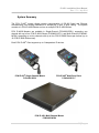
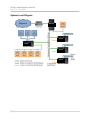
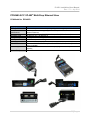
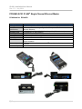
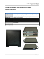
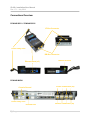
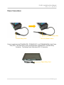
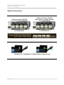
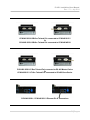
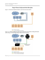
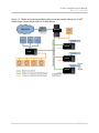
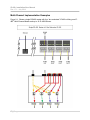
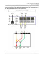
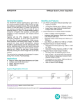
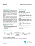
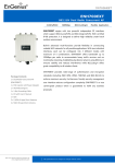
IP-485® Installation/User Manual
Rev 1.71 – July 2014
IP-485® Installation/User Manual
Rev 1.71 – July 2014
IP-485® Master/Slave
Installation/User Manual
© Copyright 2014 PCN Technology, Inc.
®
IP-485 Is a Registered Trademark of PCN Technology, Inc.
PCN Technology, Inc. | 858-434-0605 | www.pcntechnology.com
1|Page
IP-485® Installation/User Manual
Rev 1.71 – July 2014
Part Numbers Included in this Installation Manual:
PCN3485-SCC1 IP-485® Multi-Drop Ethernet Slave
UL Listed USA/Canada
PCN3485-SCS1 IP-485® Single-Channel Ethernet Master
UL Listed USA/Canada
PCN3485-MCS4 IP-485® Multi-Channel Ethernet Master
UL Listed USA/Canada
Contents:
3
System Summary
4
System Level Diagram
5
PCN3485-SCC1 IP-485® Multi-Drop Ethernet Slave
6
PCN3485-SCS1 IP-485® Single-Channel Ethernet Master
7
PCN3485-MCS4 IP-485® Multi-Channel Ethernet Master
8
Connection Overview
9
Power Connections
10
System Connections
12
Single-Channel Implementation Examples
14
Multi-Channel Implementation Examples
16
Safety Instructions
2|Page
IP-485® Installation/User Manual
Rev 1.71 – July 2014
System Summary
The PCN IP-485® system allows network communication of RS-485 Serial and Ethernet
simultaneously over existing installations of twisted pair (2 wire, 4 wire) cabling. The system
consists of a PCN IP-485® Master and one or multiple PCN IP-485® Slaves.
PCN IP-485® Masters are available in Single-Channel (PCN3485-SCS1), supporting one
channel with up to four PCN IP-485® Slaves (PCN3485-SCC1), and Multi-Channel (PCN3485MCS4), supporting up to four channels with up to four PCN IP-485® Slaves per channel (up to
16 PCN IP-485® Slaves total).
Each PCN IP-485® Client supports up to 3 independent IP devices.
PCN IP-485® Single-Channel Master
PCN3485-SCS1
PCN IP-485® Multi-Drop Slave
PCN3485-SCC1
PCN IP-485® Multi-Channel Master
PCN3485-MCS4
3|Page
IP-485® Installation/User Manual
Rev 1.71 – July 2014
System Level Diagram
MASTER
SLAVE
SLAVE
SLAVE
SLAVE
4|Page
IP-485® Installation/User Manual
Rev 1.71 – July 2014
PCN3485-SCC1 IP-485® Multi-Drop Ethernet Slave
PCN Model No. EC3485-D
Category
Wire Type
Distance
Specifications
Power
Operating Temp
Storage Temp
Humidity
Agency Approvals
Bandwidths
Connectivity
Product Family
10/100 BASE-T Multi-Drop Ethernet Slave (Part # - PCN3485-SCC1)
Twisted Pair (Standard and Proprietary Copper Media Types)
Scalable / Standard & Long Range Ethernet Capabilities – Standard Serial
Network Distances
120/240 VAC (-15% / +10%) 50/60Hz 2 Amps Max (5 Watt Nominal)
-20 Degrees C to +60 Degrees C
-40 Degrees C to +85 Degrees C
10% to 90% (non-condensing)
nd
UL Listed C US / I.T.E. E342284 / UL 60950-1, 2 Edition / FCC Part 15
Ethernet - 10/100 BASE-T Compliant / Serial 9600-19,200 Standard (76.8K &
Higher Available)
rd
PCN3485-SCC1 interfaces to standard 3 party digital and serial products &
networks
EC3485-D
5|Page
IP-485® Installation/User Manual
Rev 1.71 – July 2014
PCN3485-SCS1 IP-485® Single-Channel Ethernet Master
PCN Model No. EC3485-D
Category
Wire Type
Distance
Specifications
Power
Operating Temp
Storage Temp
Humidity
Agency Approvals
Bandwidths
Connectivity
Product Family
6|Page
10/100 BASE-T Single-Channel Ethernet Master (Part # - PCN3485-SCS1)
Twisted Pair (Standard and Proprietary Copper Media Types)
Scalable / Standard & Long Range Ethernet Capabilities – Standard Serial
Network Distances
120/240 VAC (-15% / +10%) 50/60Hz 2 Amps Max (5 Watt Nominal)
-20 Degrees C to +85 Degrees C
-40 Degrees C to +85 Degrees C
10% to 90% (non-condensing)
nd
UL Listed C US / I.T.E. E342284 / UL 60950-1, 2 Edition / FCC Part 15
Ethernet - 10/100 BASE-T Compliant / Serial 9600-19,200 Standard (76.8K &
Higher Available)
rd
PCN3485-SCS1 interfaces to standard 3 party digital and serial products &
networks
EC3485-D
IP-485® Installation/User Manual
Rev 1.71 – July 2014
PCN3485-MCS4 IP-485® Multi-Channel Ethernet Master
PCN Model No. EC3485-SA1
Category
Wire Type
Distance
Specifications
Power
Operating Temp
Storage Temp
Humidity
Agency Approvals
Bandwidths
Connectivity
Product Family
10/100 BASE-T Multi-Channel Ethernet Master (Part # - PCN3485-MCS4)
Twisted Pair (Standard and Proprietary Copper Media Types) (4 Channels)
Scalable / Standard & Long Range Ethernet Capabilities – Standard Serial
Network Distances
120/240 VAC (-15% / +10%) 50/60Hz 2 Amps Max (20 Watt Nominal)
-0 Degrees C to +55 Degrees C
-20 Degrees C to +70 Degrees C
10% to 90% (non-condensing)
nd
UL Listed C US / I.T.E. E342284 / UL 60950-1, 2 Edition / FCC Part 15
Ethernet - 10/100 BASE-T Compliant / Serial 9600-19,200 Standard (76.8K &
Higher Available)
rd
PCN3485-MCS4 interfaces to standard 3 party digital and serial products &
networks
EC3485-SA1
7|Page
IP-485® Installation/User Manual
Rev 1.71 – July 2014
Connections Overview
PCN3485-SCC1 / PCN3485-SCS1
LF-Bus Connector
Power Entry Cord
BB-Bus Connector
Ethernet Ports (x3)
Chassis Ground
PCN3485-MCS4
Chassis Ground
LF-Bus Connectors (x4)
Power Entry Cord
Ethernet Port
8|Page
BB-Bus Connectors (x4)
IP-485® Installation/User Manual
Rev 1.71 – July 2014
Power Connections
IEC C14 (Power Entry Cord)
Power Entry Cord
IEC C13 (Power Cable)
Power is supplied to the PCN3485-SCS1, PCN3485-SCC1, and PCN3485-MCS4 via the Power
Entry Cord. The Power Entry Cord is terminated with a standard IEC C14 Power Entry
Connector. The mating Power Cable has a IEC C13 connector.
Power Entry Cord
9|Page
IP-485® Installation/User Manual
Rev 1.71 – July 2014
System Connections
LF-Bus Connectors (RS-485)
to (up to) four RS-485 Masters
LF-Bus Connectors (RS-485)
With Channel 1 Jumpers Installed
to one RS-485 Master
BB-Bus Connectors (IP-485®)
to PCN3485-SCC1
BB-Bus Connectors (IP-485®)
to PCN3485-SCC1
Sticker indicates polarity and channel on each LF-Bus and BB-Bus connector.
PCN3485-SCS1 / PCN3485-SCC1 LF/BB Common to Earth Ground
10 | P a g e
IP-485® Installation/User Manual
Rev 1.71 – July 2014
PCN3485-SCS1 BB-Bus Twisted Pair connected to PCN3485-SCC1
Or
PCN3485-SCC1 BB-Bus Twisted Pair connected to PCN3485-MCS4
PCN3485-SCS1 LF-Bus Twisted Pair connected to RS-485 Master Device
Or
PCN3485-SCC1 LF-Bus Twisted Pair connected to RS-485 Slave Device
PCN3485-SCS1 / PCN3485-SCC1 Ethernet RJ-45 Connections
11 | P a g e
IP-485® Installation/User Manual
Rev 1.71 – July 2014
Single-Channel Implementation Examples
Figure 1-1: Shows two separate networks; one IP and one serial network.
Figure 1-2: Shows convergence of the same two networks over the same existing twisted pair
cable utilizing an IP-485® Single-Single Channel Server and Client.
MASTER
SLAVE
12 | P a g e
IP-485® Installation/User Manual
Rev 1.71 – July 2014
Figure 1-3: Shows multi-drop expandability of the converged network utilizing one IP-485®
Single-Single Channel Server and four IP-485® Slaves.
MASTER
SLAVE
SLAVE
SLAVE
SLAVE
13 | P a g e
IP-485® Installation/User Manual
Rev 1.71 – July 2014
Multi-Channel Implementation Examples
Figure 2-1: Shows a single RS-485 master with four “bus redundant” IP-485® utilizing one IP485® Multi-Channel Master and up to 16 IP-485® Slaves.
14 | P a g e
IP-485® Installation/User Manual
Rev 1.71 – July 2014
Figure 2-2: Shows dual RS-485 masters with independent serial IP-485® buses utilizing one IP485® Multi-Channel Master and up to eight IP-485® Slaves.
15 | P a g e
IP-485® Installation/User Manual
Rev 1.71 – July 2014
PCN Technology, Inc. IP-485® System - EC3485 Safety Manual Rev 1.71
Manufacturer: PCN Technology, Inc.
Revision 1.60 – September 2, 2011
Revision 1.71 – June 26, 2012 – Added Hot Surface Label Notices for model –D-R.
Models for this Safety Manual:
EC3485-D (-D-L), (-D-R) (-D-E):Conductive Media Communication Module Client
EC3485-SA1
: Conductive Media Communication Module Server
Special Rack Mount Installation Instructions
A. Elevated Operating Ambient – If installed in a closed or multi-unit rack assembly, the
operating ambient temperature of the rack environment may be greater than room
ambient. Therefore, consideration should be given to installing the equipment in an
environment compatible with the maximum ambient temperature (Tma) of 40 C.
B. Reduced Air Flow – Installation of the equipment in a rack or cabinet should be such that
the amount of airflow required for safe operation of the equipment is not compromised.
C. Mechanical Loading – Mounting of the equipment in the rack or cabinet should be such
that a hazardous condition is not achieved due to uneven mechanical loading.
D. Circuit Overloading – Consideration should be given to the connection of the equipment
to the supply circuit and the effect that overloading of the circuits might have on over
current protection and supply wiring. Appropriate consideration of equipment nameplate
ratings should be used when addressing this concern,
E. Reliable Earthing – Reliable earthing of rack-mounted equipment should be maintained.
Particular attention should be given to supply connections other than direct connections
to the branch circuit. (e.g. use of power strips).
F. Redundant Power Supplies - Where redundant power supplies are provided with the
equipment, each power supply shall be connected to a separate circuit to optimize the
equipment redundancy.
G. Servicing – Prior to servicing the equipment, disconnect all power supplies.
Additional Warnings
Caution (if batteries are used): Risk of explosion if battery is replaced by incorrect type. Dispose
of used batteries according to the instructions.
16 | P a g e
IP-485® Installation/User Manual
Rev 1.71 – July 2014
IP-485® Product Family Installation Overview
Product Models:
EC3485-D (-D-L), (-D-R) or (-D-E) : Conductive Media Communication Module Client
EC3485-SA1
: Conductive Media Communication Module Server
Hardware Platform PCN Proprietary Hardware
Ethernet Communication provided over modulated Twisted Pair Cabling
INTRODUCTION
The IP-485® System is a set of devices that are used to send both RS-485 and Ethernet data
over 2 wire communications cable that talk between the Server (EC3485-SA1) and several
Client (EC3485-D) Communication Modules. The primary advantage of this solution is to avoid
having to lay conduit or pull additional wires at sites for a CAT5 Ethernet cable.
The IP-485® System acts as a web of pass-through networking extension devices.
The Serial twisted pair RS-485 Connections connect to the low frequency ports (LF Bus)
connections while the connections between the Server and Client Modules both utilize the
broadband ports (BB Bus) to intercommunicate.
This implementation of the IP-485® EC3485 System has the following limitations:
• Each broadband channel (BB Bus) supports a maximum of 4 client modules.
• The maximum supported length of existing twisted pair communications wires is 300 feet.
NOTE: The installation of the IP-485® System may require installation of several wiring and
hardware assemblies. Any installation and/or modification must comply with the requirements of
the National Electrical Code (NFPA 70), the
Automotive and Marine Service Station Code (NFPA 30A) and any other applicable codes.
NOTE:
You must wear an anti-static wrist strap securely attached to an earth ground, when handling
any circuit board, electronic component or assembly, or when reaching into any site controller or
device’s computer enclosure. Do not use power tools.
17 | P a g e
IP-485® Installation/User Manual
Rev 1.71 – July 2014
INSPECTION NOTES:
1. Before opening any cartons, count the number of cartons and verify the carton count against
the supplied packing list.
2. Inspect the cartons for damage made during transit.
3. File claim information with the carrier on the bill of lading.
4. Retain cartons suspected of damage for future claim purposes.
NOTE: You must wear an anti-static wrist strap when removing electronic
components from anti-static packages. Attach the wrist strap securely to an earth
grounding point to prevent possible damage from static electricity.
5. Remove all equipment from the shipping cartons and carefully inspect for visible damage.
NOTE: Any damage should be brought to the attention of the carrier and claims made
immediately. Return all equipment to the respective cartons for protection until actual installation
is made. Save all cartons until it is certain that return shipments are not required.
SAFETY INFORMATION
Read NFPA 30A and NFPA 70 (U.S. Installations)
Before installing the equipment, the installer must read, understand and follow this manual,
NFPA 30A, NFPA 70, and applicable federal, state and local codes and regulations. Failure to
do so may adversely affect the safe use and operation of the equipment.
CSA C22.1 (Canadian Installations)
For installation in Canada the installer must read and understand this manual, CSA C22.1
(Canadian Electrical Code) and applicable federal, provincial and local codes and regulations.
Emergency Power Cutoff
NFPA30A requires that an emergency power cutoff be installed. An emergency power cutoff is a
single control that removes AC power from all site fueling equipment and submersible pumps.
Make sure the control is accessible, labeled clearly, and installed away from EC3485 units.
Make sure all employees at the installation site know where the Emergency Power Cutoff is
located and how to operate it.
18 | P a g e
IP-485® Installation/User Manual
Rev 1.71 – July 2014
Electrical Circuits
Some of the procedures in this manual involve removal and connection of components during
installation or service. Remove power from the distribution box before executing these
procedures.
Low Voltage
Do not be misled by the term "Low Voltage". Voltage potentials as low as 50 Volts may cause
death under adverse conditions.
High Voltage
High voltage of 120 volts AC is used for operation of this equipment. Death on contact may
result if safety procedures are not followed.
INSTALLATION LOCATION
The IP-485® System equipment may be installed in a variety of locations; all of the cabinets and
required wireways must be located in a non-hazardous area of an enclosed weather protected
building.
Component Preferred Location Notes
The IP-485® System mounted on table top or rack mounted near the wiring
conduits for existing system controls.
Component Width Height Depth
The IP-485® System EC3485-SA1 - 13.5 inches x 14.2 inches
The IP-485® System EC3485 conduit and Wiring requirements
Conduits used must be ¾ in. Verify that approved wire-ways and threaded metallic conduit with
tight connections are used. The recommended Data Link wiring is #18 AWG twisted pair 600
Volt oil and gasoline resistant as a minimum.
Environmental Requirements
Ensure that all cabinets are located in an area that offers easy access for service, and free air
space for cooling, 6" away from other cabinets.
Care should be taken to ensure that the temperature of the cabinets does not exceed the
operational ranges of 0°C to 50°C (32°F to 122°F)
19 | P a g e
IP-485® Installation/User Manual
Rev 1.71 – July 2014
Preliminary Wiring
The site wiring must be completed before installation of an IP-485® System device.
LF Bus and BB Bus Wiring
Two pairs of data link wires are used; one pair for LF-Bus (native RS-485 communication) and
one pair for Broadband BB-Bus communication of the IP-485® System (IP-485®).
CONFORMITY WITH STANDARDS
Ensure that all National, State, and local standards and codes are observed in site preparations,
wiring, and installation.
Power Wiring
Confirm that all 120VAC to 240VAC wiring for outdoor equipment (line, neutral, relay select,
etc.), is #14 AWG minimum (unless local codes call for 12 gauge), stranded, oil and gasoline
resistant.
Electrical Codes
Confirm that all equipment is installed in accordance with the US National Electrical Code
(NFPA 70), the automotive and Marine Service Station Code (NFPA 30A), and any other
applicable State and local codes. For installations outside the US, follow all applicable local and
international codes.
REQUIRED TOOLS
1 Small Channel Lock pliers
1 Phillips Screwdriver Set (standard sizes)
1 Slotted Screwdriver Set (standard sizes)
1 Wire Cutters
1 Anti-static Wrist Strap
1 Needle Nose Pliers
1 Wire Strippers
16 to 32 Wire Nuts
1 Volt Meter
1 Diagonal Cutters
1 Standard Drill Bit Set
1 Drill
20 | P a g e
IP-485® Installation/User Manual
Rev 1.71 – July 2014
INSTALLATION OVERVIEW
When possible, mount the IP-485® Master EC3485-SA1 unit in the equipment rack with access
to the wiring trough where the EC3485 communication wires are located.
NOTE: The IP-485® System’s Server mounting location may be in a 19” rack mount. Alternate
installation of the EC3485-SA1 can be a tabletop mount. Please be careful that all boards and
components that are susceptible to damage from static electrical discharge are protected by
wearing an anti-static wrist strap.
NOTE: Data wires may have been bundled together in parallel within the wiring trough. Unbundle the wire pairs and splice extensions if needed so that each discrete RS-485 wire pair
reaches the location of the IP-485® System unit.
NOTE: Connect the ground wire to an appropriate grounding location.
The IP-485® Master EC3485-SA1 unit should be mounted in such a
way that there is visual access to the XMIT and RCV LEDs which are next to the LF Bus and BB
Bus connectors. The opposite end of the box has the Status display LEDs and should also be
visible.
The standard configuration is used for any site controller that does NOT require discrete or
separate RS-485 channels. The EC3485-SA1 supports up to four separate LF-Bus and BB-Bus
channels, but can output as one single communication channel. The IP-485® System acts as a
communication pass-though device.
NOTE: Each IP-485® System Server’s LF bus plug connects to only 1 channel on the site
controller via the right side terminals; the left side terminals are not used. In the single channel
(standard) configuration, the plugs for channels 2, 3 and 4 should have the channel 1 jumper
installed.
21 | P a g e
IP-485® Installation/User Manual
Rev 1.71 – July 2014
Product Specifications
EC3485-D (-D-L), (-D-R) or (-D-E) Client Module
Power: 120/240 VAC ( -15% / +10% ) 50/60Hz 2 Amps Max. (5 Watt Nom.)
Operating Temperature: -20 Deg C to +60 Deg C
Storage Temperature: -40 Deg C to +85 Deg C
Humidity: 10% to 90% (non-condensing)
EC3485-D-R (-D-E) Specific Condition of Acceptability with 60417-2-IEC-5041 Hot Surface labeling
Qualified Specification Operating Temperature: -20 Deg C to +70 Deg C
EC3485-SA1 Server Unit
Power: 120/240 VAC ( -15% / +10% ) 50/60Hz 2 Amps Max. (20 Watt Nom.)
Operating Temperature: 0 Deg C to +55 Deg C
Storage Temperature: -20 Deg C to +70 Deg C
Humidity: 10% to 90% (non-condensing)
POWER NOTES:
1.)
2.)
3.)
4.)
Socket-outlet shall be installed near the equipment and shall be easily accessible.
No user serviceable parts inside.
Caution: Double pole/neutral fusing.
Marking of Hot Parts - Parts inside the equipment that are hot and may be touched are
marked with
this symbol 60417-2-IEC-5041 adjacent to the part.
Agency Approvals
EC3485-D (-D-R) or (-D-E) Specific Approval
I.T.E.
File No. E342284
EC3485 (-D) (-D-L) (-SA1) - UL Listed C US
EC3485 (-D-R) (-D-E) - UL Recognized C US
UL60950-1, 2nd Edition
Class 1 Division 2 Group D (EQXX)
File No. MH48432
Hazardous Location C US
--------------------------------------------------------------Note:
EC3485-SA1, (-D), (-D-L) models
Are not MH48432 [C1 D2] approved
This device complies with Part 15 of the FCC Rules. Operation is subject to the following two
conditions: (1) this device may not cause harmful interference, and (2) this device must accept
any interference received, including interference that may cause undesired operation.
Manufactured by:
PCN Technology, Inc. 16450 Via Esprillo, San Diego, CA 92127 www.PCNtechnology.com
22 | P a g e
IP-485® Installation/User Manual
Rev 1.71 – July 2014
Page Left Intentionally Blank
23 | P a g e
IP-485® Installation/User Manual
Rev 1.71 – July 2014
© Copyright 2014 PCN Technology, Inc.
®
IP-485 Is a Registered Trademark of PCN Technology, Inc.
PCN Technology, Inc. | 858-434-0605 | www.pcntechnology.com
24 | P a g e