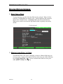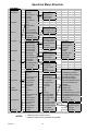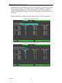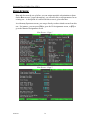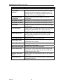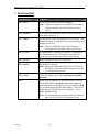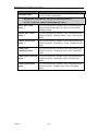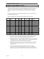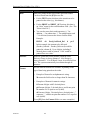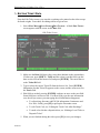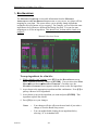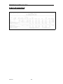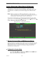
1
Spectrum User Guide Version 6.24 2/9/2010 Command Alkon Inc. 5168 Blazer Parkway Dublin, Ohio 43017 Service Dept: 614.792.0677 Fax: 614.793.0608 Part Number: 25302 © 1970 - 2010 Command Alkon Incorporated. All rights reserved. Command Alkon Incorporated believes the statements contained herein are accurate as of the date of publication of this document. HOWEVER, COMMAND ALKON INCORPORATED HEREBY DISCLAIMS ALL WARRANTIES EITHER EXPRESSED OR IMPLIED, INCLUDING WITHOUT LIMITATION ANY IMPLIED WARRANT OF MERCHANTABILITY OR FITNESS FOR A PARTICULAR PURPOSE. In no event will Command Alkon Incorporated be liable for any damages, including any lost profits, lost savings, or other incidental or consequential damage arising out of the use of or inability to use any information provided through this publication, even if Command Alkon Incorporated has been advised of the possibility of such damages, or for any claim by any other party. Some states do not allow the limitation or exclusion of liability or consequential damages, so the above limitation may not apply. This information is not intended to be an assertion of future action. The contents of this document are for informational purposes only and are subject to change without notice. Command Alkon Incorporated expressly reserves the right to change or withdraw current products that may or may not have the same characteristics listed in this publication. Should Command Alkon Incorporated modify its products in a way that may affect the information contained in this publication, Command Alkon Incorporated assumes no obligation whatever to inform any user of the modification. This publication may contain technical inaccuracies or typographical errors. Command Alkon Incorporated assumes no responsibility for any errors that may appear in this manual. This publication is intended only for the direct benefit of users of Command Alkon Incorporated products. This manual may not be used for any purposes other than those for which it is provided. Information disclosed herein was originated by and is the property of Command Alkon Incorporated, and, except for rights granted by written consent, such information shall not be disclosed, disseminated, or duplicated in whole or in part. Command Alkon Incorporated reserves all patent, proprietary, design, manufacturing, use, and reproduction rights. Command Alkon Incorporated 1800 International Park Drive, Suite 400 Birmingham, AL 35243-4232 (205) 879-3282 5168 Blazer Parkway Dublin, OH 43017-1339 (614) 799-6650 www.commandalkon.com Microsoft, Windows, and SQL are trademarks of Microsoft Corporation of Redmond, Washington. COMMANDseries (and the names of its components, such as COMMANDconcrete and COMMANDnetwork), Spectrum, Eagle, and COMMANDbatch are registered trademarks of Command Alkon Incorporated. All rights reserved. 02/09/10 2 Spectrum User’s Guide (Ver. 6.24+) CONTENTS Contents ............................................................................................................................. 3 Introduction..................................................................................................................... 10 AUDIENCE ................................................................................................................................................ 10 REGULATORY COMPLIANCE ..................................................................................................................... 10 ª Mn/DOT Certification ............................................................................................................... 10 ª California Type Evaluation Program (CTEP) Approval .......................................................... 10 REVISIONS ................................................................................................................................................ 11 User’s Guide Terminology ............................................................................................. 13 ª ª ª ª ª ª Menu, Screen, and Database Names......................................................................................... 13 Menu and Screen Locations ...................................................................................................... 13 Field Names............................................................................................................................... 13 Keystroke Designations............................................................................................................. 13 Features & Functions................................................................................................................ 13 References to Other Sections of This Guide .............................................................................. 13 Spectrum System Terminology...................................................................................... 14 ª ª ª ª ª ª Database ................................................................................................................................... 14 Database Table ......................................................................................................................... 14 Record ....................................................................................................................................... 14 Field .......................................................................................................................................... 14 Nodes/Terminals........................................................................................................................ 14 Character .................................................................................................................................. 14 New Features ................................................................................................................... 15 Power-up and Shutdown Procedures............................................................................ 18 POWER-UP PROCEDURE ........................................................................................................................... 18 RESTARTING A NODE DURING THE DAY ................................................................................................... 19 BOOTING INTO DOS ................................................................................................................................. 19 USING WINDOWS FROM THE SPECTRUM ................................................................................................... 20 SHUTDOWN PROCEDURE .......................................................................................................................... 20 ª Quit Spectrum Procedure.......................................................................................................... 20 Navigating the System .................................................................................................... 21 ACCESSING SCREENS ................................................................................................................................ 21 MOVING WITHIN SCREENS ....................................................................................................................... 22 ª Selecting a Field........................................................................................................................ 22 ª Moving from Field to Field ....................................................................................................... 22 ª Selecting Entries from Browseable Fields ................................................................................ 23 ª Accessing Field Help................................................................................................................. 24 EXITING MENUS AND SCREENS ................................................................................................................ 24 Menu Layout ................................................................................................................... 25 ª ª ª Sub-Menus................................................................................................................................. 25 “*” Listed Beside a Report Item ............................................................................................... 25 “Nothing” Listed Beside a Report Item .................................................................................... 25 Basic Screen Layout........................................................................................................ 27 ª ª ª ª ª Current Time ............................................................................................................................. 28 Screen Title................................................................................................................................ 28 Function Key Prompts for Batching.......................................................................................... 28 Escape Key Prompt ................................................................................................................... 28 Function Key Prompts (Screen-Specific) .................................................................................. 28 The Spectrum Database ................................................................................................. 29 WHAT IS THE DATABASE? ........................................................................................................................ 29 HOW IS THE DATABASE ORGANIZED? ...................................................................................................... 29 02/09/10 3 Spectrum User’s Guide (Ver. 6.24+) WHAT IS THE PURPOSE OF THE DATABASE? ............................................................................................. 29 TO ADD A DATABASE TABLE RECORD ..................................................................................................... 30 TO EDIT A DATABASE TABLE RECORD ..................................................................................................... 30 TO VIEW A DATABASE TABLE RECORD .................................................................................................... 31 TO DELETE A DATABASE TABLE RECORD ................................................................................................ 31 SCREENS NOT DISCUSSED IN THIS SECTION ............................................................................................. 31 SALES TAX RATES .................................................................................................................................... 32 ª Fields......................................................................................................................................... 32 ª Function Keys............................................................................................................................ 32 CUSTOMERS.............................................................................................................................................. 33 ª Fields......................................................................................................................................... 33 ª Function Keys............................................................................................................................ 34 INGREDIENTS ............................................................................................................................................ 35 ª Fields......................................................................................................................................... 36 ª Function Keys............................................................................................................................ 42 ª Ingredient Groups ..................................................................................................................... 42 ª Absolute Value Ingredients ....................................................................................................... 43 ª Percentage Ingredients ............................................................................................................. 43 ª Hundred Weight Ingredients ..................................................................................................... 44 ª Ingredient Effectiveness ............................................................................................................ 44 MIX DESIGNS ........................................................................................................................................... 45 ª Fields......................................................................................................................................... 45 ª Function Keys............................................................................................................................ 48 ª To Create a Mix Design ............................................................................................................ 50 ª To Change an Ingredient in All Mixes ...................................................................................... 51 ª To View Usage for a “Single” Mix Design ............................................................................... 51 ª To View Usage for “All” Mix Designs...................................................................................... 52 ADMIX DESIGNS ....................................................................................................................................... 53 ª Fields......................................................................................................................................... 53 ª Function Keys............................................................................................................................ 54 ª To Create an Admix Design ...................................................................................................... 55 ª Ulink-Style Admix Modifiers ..................................................................................................... 56 RESALE PRODUCTS ................................................................................................................................... 57 ª Fields......................................................................................................................................... 57 ª Function Keys............................................................................................................................ 59 ª Ingredients Used as Resale Products........................................................................................ 60 ª Recording Incoming Inventory – Resale Products.................................................................... 61 TRUCKS .................................................................................................................................................... 62 ª Fields......................................................................................................................................... 62 ª Function Keys............................................................................................................................ 63 PROJECTS ................................................................................................................................................. 64 ª Fields......................................................................................................................................... 65 ª Function Keys............................................................................................................................ 67 ª Project Pricing .......................................................................................................................... 67 ª Consistence and Ext. Description ............................................................................................. 68 EDIT MMM DESCRIPTION ........................................................................................................................ 69 SLUMP TABLES ......................................................................................................................................... 70 ª What Is Slump? ......................................................................................................................... 70 ª Slump Calculations - Simplified ................................................................................................ 70 ª Setting Up Slump Tables ........................................................................................................... 72 ª Calculating Slump Using Slump Tables.................................................................................... 73 Configuring Plant Devices.............................................................................................. 75 BINS SCREEN ............................................................................................................................................ 76 ª Fields......................................................................................................................................... 77 ª Feed Configurations.................................................................................................................. 81 02/09/10 4 Spectrum User’s Guide (Ver. 6.24+) Feed Types ........................................................................................................................................... 81 Possible Feed Configuration................................................................................................................. 82 SCALES SCREEN ....................................................................................................................................... 85 ª Fields......................................................................................................................................... 86 ª Motion Detection....................................................................................................................... 89 ª Setup..................................................................................................................................................... 89 Operation .............................................................................................................................................. 89 Flow Control Dampening.......................................................................................................... 91 Setup..................................................................................................................................................... 91 METERED LIQUIDS ................................................................................................................................... 93 ª Fields......................................................................................................................................... 93 ADMIXTURE BOTTLES .............................................................................................................................. 96 ª Fields......................................................................................................................................... 96 HOLDING TANKS ...................................................................................................................................... 98 ª Fields......................................................................................................................................... 98 CONVEYOR BELTS .................................................................................................................................. 100 ª Fields....................................................................................................................................... 100 EXTRA DEVICES ..................................................................................................................................... 102 ª Fields....................................................................................................................................... 102 Assigning Materials to Bins & Bottles ........................................................................ 104 MATERIAL ASSIGNMENTS SCREEN ......................................................................................................... 104 ª To Assign Materials to a Device ............................................................................................. 104 ª Fields....................................................................................................................................... 105 ª Function Keys.......................................................................................................................... 105 AUTO BIN SWITCHING ............................................................................................................................ 106 ª Setup........................................................................................................................................ 106 ª Operation ................................................................................................................................ 106 ª Ticket Printing for Switched Bins............................................................................................ 107 Setting Feed Destinations ............................................................................................. 108 FEED DESTINATIONS SCREEN ................................................................................................................. 108 ª Fields....................................................................................................................................... 108 ª Function Keys.......................................................................................................................... 109 DEVICE PROPERTY SETS ......................................................................................................................... 110 ª Adding a New Property Set ..................................................................................................... 110 ª Editing an Existing Property Set ............................................................................................. 111 ª Deleting a device property set................................................................................................. 111 ª Manual Material Monitoring of PSET IO’s ............................................................................ 111 Batching & System Defaults ........................................................................................ 113 BATCHING DEFAULTS SCREEN ............................................................................................................... 113 ª Fields....................................................................................................................................... 114 SYSTEM DEFAULTS................................................................................................................................. 119 ª Fields....................................................................................................................................... 120 Material Calculations Screen....................................................................................... 123 OVERVIEW.............................................................................................................................................. 123 STANDARD CONFIGURATION .................................................................................................................. 124 FIELDS – MATERIAL CALCULATIONS SCREEN ........................................................................................ 124 FUNCTION KEYS – MATERIAL CALCULATIONS SCREEN ......................................................................... 125 MATERIAL CALCULATION TYPES ........................................................................................................... 126 Slurry Calculations ....................................................................................................... 128 SETUPS ................................................................................................................................................... 128 Corrections Based on Ice.............................................................................................. 130 Creating Manual Station Labels ................................................................................. 131 Creating Ticket Layouts (Scripts) ............................................................................... 132 THE TICKET LAYOUT EDITOR SCREEN ................................................................................................... 132 02/09/10 Fields .................................................................................................................................................. 133 5 Spectrum User’s Guide (Ver. 6.24+) Function Keys..................................................................................................................................... 136 THE TICKET ALIAS FILE ......................................................................................................................... 137 ª Fields....................................................................................................................................... 137 ª To Add an Alias Name............................................................................................................. 138 ª To Change an Alias Name....................................................................................................... 138 CREATING A NEW TICKET SCRIPT .......................................................................................................... 139 SPECIFYING WHICH TICKET SCRIPT TO USE ........................................................................................... 142 EDITING AN EXISTING TICKET SCRIPT .................................................................................................... 142 Printer Setup Screen..................................................................................................... 143 FIELDS – PRINTER SETUP SCREEN .......................................................................................................... 144 MULTI-BATCH PRINTING ........................................................................................................................ 146 SELECTING BATCH WEIGHT ITEMS FOR PRINTING .................................................................................. 146 BAR CODE PRINTING .............................................................................................................................. 148 ª Example: Printing a Bar-Code Ticket Number ...................................................................... 148 Bar Code Escape Sequence ................................................................................................................ 148 Print Bar Code Escape Sequence........................................................................................................ 149 Ticket Layout Editor Entries .............................................................................................................. 149 Configuring a Printer ................................................................................................... 150 TO SET UP A PRINTER............................................................................................................................. 150 ª Fields – Port Parameters Screen ............................................................................................ 151 ª Fields – Plant Screen .............................................................................................................. 155 Inventory........................................................................................................................ 158 OVERVIEW OF SPECTRUM INVENTORY FUNCTIONS ................................................................................ 158 INGREDIENT INVENTORY LEVELS – “SINGLE” PLANT ............................................................................. 159 ª Fields....................................................................................................................................... 160 ª Function Keys.......................................................................................................................... 160 INGREDIENT INVENTORY LEVELS – “ALL” PLANTS ................................................................................ 160 INGREDIENT USAGE DATA – “SINGLE” PLANT ....................................................................................... 161 ª Fields....................................................................................................................................... 162 ª Function Keys.......................................................................................................................... 162 INGREDIENT USAGE DATA – “ALL” PLANTS .......................................................................................... 162 RECORDING INCOMING INVENTORY - INGREDIENTS ............................................................................... 163 ª Function Keys.......................................................................................................................... 164 CLEARING INVENTORY ........................................................................................................................... 164 Setting Up User Accounts............................................................................................. 165 ª Fields – User Setup Screen ..................................................................................................... 166 USER SECURITY...................................................................................................................................... 168 Batching Operations ..................................................................................................... 170 INTRODUCTION ....................................................................................................................................... 170 ª Batching Cycle ........................................................................................................................ 170 ª Preact ...................................................................................................................................... 170 ª Feed Types............................................................................................................................... 171 Fast Feed ............................................................................................................................................ 171 Timed Feed......................................................................................................................................... 171 Jog Feed.............................................................................................................................................. 171 ª ª ª Multi-Batching ........................................................................................................................ 172 Feed Sequencing ..................................................................................................................... 172 Discharge Cycle ...................................................................................................................... 173 BASIC STEPS FOR AUTOMATIC BATCHING .............................................................................................. 174 SCREENS USED FOR AUTOMATIC BATCHING .......................................................................................... 175 ª Order Index and Load Index Screens...................................................................................... 175 ª 02/09/10 Fields - Order Index............................................................................................................................ 176 Function Keys - Order Index .............................................................................................................. 177 Fields - Load Index............................................................................................................................. 178 Function Keys - Load Index ............................................................................................................... 179 Order Entry Screen ................................................................................................................. 180 6 Spectrum User’s Guide (Ver. 6.24+) ª Fields .................................................................................................................................................. 180 Function Keys..................................................................................................................................... 182 To Enter an Order............................................................................................................................... 184 To Edit an Order................................................................................................................................. 184 To Copy an Order............................................................................................................................... 187 Concrete Calculator Screen .................................................................................................... 189 ª To Calculate Rectangular Shapes ....................................................................................................... 190 To Calculate Cylindrical Shapes ........................................................................................................ 190 Batch Setup Screen.................................................................................................................. 191 ª Fields .................................................................................................................................................. 192 Function Keys..................................................................................................................................... 194 Adjusting Batch Information .............................................................................................................. 195 The Graph Screen.................................................................................................................... 207 Fields – Graph Screen ........................................................................................................................ 209 Function Keys – Graph Screen ........................................................................................................... 210 Starting Discharge .............................................................................................................................. 211 Aborting Batches ................................................................................................................................ 211 TICKET PRINTING ................................................................................................................................... 212 ª Overview.................................................................................................................................. 212 ª Sample Ticket .......................................................................................................................... 213 ª Tolerance Error Symbols ........................................................................................................ 214 ª Editing Ticket Data ................................................................................................................. 215 ª Making a Local Ticket a Dispatch Ticket................................................................................ 216 ª Reprinting Tickets ................................................................................................................... 216 To Reprint the Last Ticket.................................................................................................................. 216 To Reprint an Older Ticket................................................................................................................. 216 ª Ticket Reports.......................................................................................................................... 216 BATCH WEIGHTS .................................................................................................................................... 217 ª Common Items on Batch Weight Reports................................................................................ 217 ª Tolerance Error Symbols ........................................................................................................ 221 ADVANCED BATCHING FEATURES .......................................................................................................... 222 ª Multi-Batching ........................................................................................................................ 222 ª Quick Load .............................................................................................................................. 224 ª ª ª To Create Load Information Using Quick Load................................................................................. 224 To edit Quick Load information:........................................................................................................ 225 To batch a Quick Load batch:............................................................................................................. 225 Quick Ticket............................................................................................................................. 226 Bin Swapping .......................................................................................................................... 227 Quick Edit................................................................................................................................ 228 ª Fields .................................................................................................................................................. 228 Function Keys..................................................................................................................................... 228 Material Overview................................................................................................................... 229 ª Continuous Run .................................................................................................................................. 222 Freewheeling ...................................................................................................................................... 223 Fields .................................................................................................................................................. 229 Function Keys..................................................................................................................................... 230 To Reassign Ingredients ..................................................................................................................... 230 To Activate/Deactivate a Device........................................................................................................ 231 To Change Feed and Discharge Parameters ....................................................................................... 231 Truck Washout......................................................................................................................... 232 Mixer Operation (For Plants with Mixers) ................................................................ 233 OVERVIEW.............................................................................................................................................. 233 MIXERS SCREEN ..................................................................................................................................... 234 ª Fields....................................................................................................................................... 234 Reports ........................................................................................................................... 238 PRINTING REPORTS................................................................................................................................. 238 CANCELING PRINTING OF ALL REPORTS ................................................................................................. 239 DISPLAY BATCH WEIGHTS REPORT ........................................................................................................ 239 02/09/10 7 Spectrum User’s Guide (Ver. 6.24+) BATCH WEIGHTS REPORT (BY DATE) ..................................................................................................... 241 BATCH WEIGHTS REPORT (BY LOAD)..................................................................................................... 242 INCOMING INVENTORY REPORT.............................................................................................................. 243 MATERIAL USAGE BY MATERIAL........................................................................................................... 244 MATERIAL USAGE BY PLANT ................................................................................................................. 245 MATERIAL USAGE BY BIN ...................................................................................................................... 246 MIX INVENTORY ..................................................................................................................................... 247 RESALE PRODUCT INVENTORY ............................................................................................................... 248 AVERAGE MOISTURE REPORT ................................................................................................................ 249 INGREDIENT LISTING .............................................................................................................................. 250 MIX DESIGN LISTING.............................................................................................................................. 251 MIX DESIGN SUMMARY.......................................................................................................................... 252 CUSTOMER LISTING ................................................................................................................................ 253 CURRENT ORDERS .................................................................................................................................. 254 ALL ORDERS .......................................................................................................................................... 255 SELECT ORDER DATES ........................................................................................................................... 256 LOADS BY ORDER .................................................................................................................................. 257 ORDERS BY PLANT ................................................................................................................................. 258 PROJECT LISTING.................................................................................................................................... 259 PROJECTS BY CUSTOMER ....................................................................................................................... 260 EXPIRED PROJECTS ................................................................................................................................. 261 PROJECTS BY LAST USED DATE ............................................................................................................. 262 RESALE PRODUCTS LISTING ................................................................................................................... 263 C.O.D. TICKETS ..................................................................................................................................... 264 VOIDED TICKETS .................................................................................................................................... 265 TICKETS BY CUSTOMER .......................................................................................................................... 266 MATERIAL COSTS ................................................................................................................................... 267 FLEET UTILIZATION ................................................................................................................................ 268 TRUCK PRODUCTION REPORT ................................................................................................................. 269 MANUAL MATERIAL MONITOR .............................................................................................................. 270 SEQUENCE LISTING ................................................................................................................................ 271 End of Day Procedures................................................................................................. 272 CATEGORIES ........................................................................................................................................... 272 SELECTING WHAT TO RUN ..................................................................................................................... 272 RUNNING “END OF” PROCESSES ............................................................................................................. 274 Function Keys – The End of Day Procedure Screen .......................................................................... 275 EXPORTING BATCH WEIGHTS TO QC HELPER ........................................................................................ 276 ª To Export Batch Weights: ....................................................................................................... 276 PROPER SHUTDOWN WHEN EOD IS NOT RUN ...................................................................................... 278 Disk Utilities .................................................................................................................. 279 FLOPPY/REMOVABLE MEDIA BACKUP & RESTORE ................................................................................ 280 ª Backups To Floppy Disk or USB Removable Device.............................................................. 280 ª To Back Up to Floppy Disk:............................................................................................................... 280 To Back Up to USB Removable Device: ........................................................................................... 281 Restores from Floppy Disk or USB Removable Device .......................................................... 282 To Restore from Floppy Disk:............................................................................................................ 282 To Restore from USB Removable Device:......................................................................................... 282 HARD DISK BACKUP & RESTORE ........................................................................................................... 283 ª To Back Up to Hard Disk:....................................................................................................... 283 ª To Restore from Hard Disk:.................................................................................................... 284 BATCH WEIGHTS BACKUP & RESTORE................................................................................................... 286 ª To Backup Batch Weights: ...................................................................................................... 286 ª To Restore Batch Weights: ...................................................................................................... 287 EXPORT TICKETS TO DOS FILE .............................................................................................................. 288 ª To Export Ticket Data:............................................................................................................ 288 EXPORT BATCH WEIGHTS TO QC HELPER .............................................................................................. 290 02/09/10 8 Spectrum User’s Guide (Ver. 6.24+) ª To Export Batch Weights: ....................................................................................................... 290 FORMAT DISKS ....................................................................................................................................... 292 ª To Format a Floppy Disk:....................................................................................................... 292 ª Formatting a USB Removable Device for QNX ...................................................................... 293 ª Formatting a USB Removable Device for DOS ...................................................................... 293 IMPORT DATA FILES ............................................................................................................................... 295 ª To Import Mix Designs: .......................................................................................................... 295 Index............................................................................................................................... 297 APPENDICES: A: E-Z CAL MANUAL STATION B: MOISTURE PROBE INSTALLATION C: SPECTRUM SETUP FOR STATE INSPECTIONS D: MIX DESIGN POLYNOMIALS SETUP GUIDE 02/09/10 9 Spectrum User’s Guide (Ver. 6.24+) INTRODUCTION Congratulations on your purchase of Command Alkon’s Spectrum Batching System for your ready-mix concrete company. Spectrum offers you complete ready-mix operations functionality; including batching, reporting, quality control, scheduling, order tracking, inventory, dispatching, and mix design maintenance management. All aspects of the Spectrum System are linked through a central database. Spectrum can also be linked to existing accounting or general ledger software. Spectrum also offers you direct control of your concrete mixing and batching activities. With Command Alkon’s moisture probe, you can generate an accurate reading of material moistures at any point in the batching process, allowing you to accurately determine the amount of water necessary for the desired mix. This Guide is designed to help you make the most of your new Spectrum System. We’re sure you’ll find that working with Spectrum will lead to more efficient operation of your ready-mix concrete company. Ensuring the accuracy and speed of your batching processes will allow you to react quickly to changing conditions and improve your ability to respond to customer needs. AUDIENCE This Guide is intended for the use of managers, dispatchers, and batch persons who operate ready-mix concrete plants. Additional technical material regarding the Spectrum System is available through Command Alkon Technical Support at (614) 792-0677. REGULATORY COMPLIANCE ª MN/DOT CERTIFICATION Spectrum V6.19B (and later) produces a Certificate of Compliance (concrete batch ticket) that complies with Mn/DOT Specification 2461.4D7a, dated September 7, 2001. ª CALIFORNIA TYPE EVALUATION PROGRAM (CTEP) APPROVAL Certificate Number: 5534-07 This device was evaluated under the California Type Evaluation Program (CTEP) and was found to comply with the applicable technical requirements of California Code of Regulations for “Weighing and Measuring Devices”. 02/09/10 10 Spectrum User’s Guide (Ver. 6.24+) REVISIONS September 22, 2000 • • • • Updated section on Exporting Batch Weights to include the option of exporting load-level weights. Restructured Ticket Printing information. Added more details about batch weights (on reports and tickets). Added section on Mixer Operation. June 20, 2001 Added information about using math calculations in the Data column of the Ticket Layout Editor (see “The Ticket Layout Editor Screen”). August 21, 2001 Added sub-section about Ulink Admix Modifiers to the “Admix Designs” section. August 28, 2001 Added example of Truck Production Report. September 7, 2001 September 11, 2001 • Added section on Slump Tables and slump calculations. • Updated list of new features for V6.18. Added sections on Batching Defaults and System Defaults screens. September 20, 2001 Added section on Device Property Sets. October 9, 2001 Updated description of Batch Weight options and moved this information from the Reports section to just before the Advanced Batching Features section. October 12, 2001 • Updated field descriptions for Ingredients screen. • Replaced old disclaimer page with the new one. Updated field descriptions for Batch Weights reports according to new oven dry moisture calculation changes. Added sections on Material Calculations screen and Slurry Calculations. October 15, 2001 October 16, 2001 February 27, 2002 • • March 1, 2002 April 4, 2002 August 19, 2003 to September 30, 2003 Added section on setting up the printer, and updated description of ‘Tracepoints’ field of Port Parameters screen. Updated description of ‘Record SOZ as Batched?’ field of Ingredients screen. • Updated description of ‘Tracepoints’ field of Ingredients screen. • Updated descriptions of items on Batch Weights reports. Added sections on “Editing Truck Code Before Discharge” and “Editing Truck Code After Discharge” to the “Adjusting Batching Information” section. Updated the user guide for V6.19. Consolidated the U.S. and Metric user guides into one. Note: The U.K. switch_date script is now incorporated into the general release. The script file makes the required .profile and 02/09/10 11 Spectrum User’s Guide (Ver. 6.24+) message file modifications then recompiles the msgfile.bin file. Backup files are created as before. April 5, 2004 Updated user guide for V6.20A. May 3, 2004 Final proof for print vendor. November 16, 2004 Added appendices to the PDF for the print vendor. March 16, 2005 Updated the manual for V6.21A (see New Features for a list of features added to this guide). March 17, 2005 Updated descriptions for Fast, Timed, and Jog feed types. March 21, 2005 Corrected description of Jog Feed and reviewed final proof for print vendor. May 9, 2006 Added feature enhancements for V6.22A and V6.22B. Moved the section on setting up a serial scale to the External Serial Device Setup Guide. December 20, 2006 Re-posted manual on Command Alkon website. January 5, 2007 • • July 31, 2007 August 14, 2007 Updated the manual with the following feature enhancement for V6.23A: The Batch Weight Options screen now includes a flag called “Print Batched UOM” that must be set to “Y” for state inspections so that printed scale or meter values use the same UOM as their respective measuring devices. Added a section to the Introduction about regulatory compliance with Mn/DOT and CTEP state inspection requirements. • Revised description of the Allow Link Mix Conversion field of the System Defaults screen to require that this flag be set to ‘Y’. • Prepared new V6.23 masters for the print vendor. Added CTEP approval number (5534-07) to page 10. July 10, 2008 Replaced all instances of Zip disk with USB removable device. Change is effective for V6.23B.08 and later. September 23, 2008 Added the section: “Making a Local Ticket a Dispatch Ticket”. November 10, 2008 Updated this manual for V6.24A. April 28, 2009 Added new User Setup screen example showing the Enforce Based On Check field, along with a description of this new field. July 6, 2009 Updated the list of Calculation Types used on the Material Calculations Screen to include the “I” and “J” types that deal with excluding returned concrete amounts from load size calculations. Also added a text description of each calculation type. Feb. 9, 2010 Added description of “Auto HH:MM:SS” and “Manual HH:MM:SS” to Common Items on Batch Weight Reports section. 02/09/10 12 Spectrum User’s Guide (Ver. 6.24+) USER’S GUIDE TERMINOLOGY The following conventions are used throughout this Guide to bring attention to fields, screens, menus, keystroke commands, and features. ª MENU, SCREEN, AND DATABASE NAMES When a particular Spectrum menu, screen, or database table is discussed in the text, its name appears in the following style: CUSTOMERS screen ª MENU AND SCREEN LOCATIONS Screen locations within the Spectrum system are indicated as follows: MAIN MENU DATA ENTRY CUSTOMERS For example, to access the CUSTOMERS screen indicated above, start at the MAIN MENU, select “Data Entry,” then select “Customers” from the DATA ENTRY menu. ª FIELD NAMES When a field is discussed, its name appears in the following style: Order field ª KEYSTROKE DESIGNATIONS Keyboard letter keys are displayed in bold font inside square brackets as follows: [F2] [ENTER] [TAB] Keystroke combinations (pressing two or more keys at the same time) are shown with a plus sign (+) between the key’s names. Example: [ALT + C] ª FEATURES & FUNCTIONS Where possible, features and system functions appear in the following formats: Batch on Receipt feature Update Inventory function ª REFERENCES TO OTHER SECTIONS OF THIS GUIDE Sections of this Guide are cross-referenced as follows: (See “Batching Operations” for more information.) 02/09/10 13 Spectrum User’s Guide (Ver. 6.24+) SPECTRUM SYSTEM TERMINOLOGY The following terminology is used throughout this Guide when referring to different parts of the Spectrum System. ª DATABASE A database is a group of electronically stored information that can be retrieved and used so that it does not have to be re-typed every time it is needed. The Spectrum System contains a single database for your company. Most of the information stored in the Spectrum database is accessible through DATA ENTRY screens. ª DATABASE TABLE The Spectrum System database consists of many tables. Each table contains separate, like information (e.g., information on customers is stored in its own CUSTOMER database table). ª RECORD A record is a collection of information about a specific item in a database table. A table can have many records. For example, the information stored for one customer is a record. Records are composed from information stored in fields. Records are viewed, created, and modified using DATA ENTRY screens. ª FIELD All data is entered into fields. Each time you view a Spectrum screen, you are looking at an assortment of fields. Think of a screen as a form with fields as blanks where you enter data. Each field contains a particular type of data (e.g., Customer Name, Unit Price, Project Number, etc.). ª NODES/TERMINALS All IBM PC-compatible computers are called Nodes. Attached serial terminals are referred to as Terminals. ª CHARACTER The term character refers to a single letter, symbol, or digit. For example, “A”, “*”, and “2” are each a single character. In contrast, the number “100” is three characters long. Each field consists of a certain number of characters. 02/09/10 14 Spectrum User’s Guide (Ver. 6.24+) NEW FEATURES The following features have been added to the Spectrum software since Version 6.18. The current software version is 6.23. Note: Information about feature enhancements is provided in the Release Notes for the appropriate Spectrum version. FEATURE Multi-Tier Tolerances Batch Size Round By Factor Final MnDOT Changes Extra Devices Now Displayed on Graphics Screen Specific Gravity can now be printed with Batch Weights User Security not needed to Print Event Log Effectiveness Field now has 2 Decimal Places EN-206 Changes 02/09/10 DESCRIPTION VER. You can now enter tolerances for small loads. Per ASTM guidelines, once set of tolerances is used if the target weight is over 30 percent of the scale capacity, and another set is used if the target weight is under 30 percent of the scale capacity. A field for entering a round-by factor for batch sizes has been added to page 2 of the Batching Defaults screen (New York State requirement). You can now print MnDOT standard column headers on the batch weights portion of tickets by selecting this option on the Batch Weights Options screen. Extra devices with temper/external interfaces are now displayed on the Graphics, Readout Display, and Scale Meter I/O screens. New fields were also added to the Extra Devices Screen. You can now select this option on the Batch Weight Options screen so that the specific gravity percentage for gray water systems can be printed. Users who do not have access to the Plant Setup menu can now print the Event Log from the Readout Display screen, which can be accessed from the Reports menu or by pressing <F3> from the Batch Setup screen. This field on the Ingredients screen now allows two decimal places. Two new fields have been added to some Spectrum screens to describe concrete production in terminology required by the EN 206 Standards. The new fields are: Ext. Description and Consistence. Affected forms are Mix Designs, Projects, Orders, Batch Setup, and Ticket Editor. 6.19B 15 6.19B 6.19B 6.19B 6.19B 6.19B 6.19B 6.20A Spectrum User’s Guide (Ver. 6.24+) FEATURE DESCRIPTION VER. Average Moisture Report This report is new. It shows average monthly moisture for materials used for batching. Both SSD and total moisture averages are shown. The “Average Moisture” selection has been added to the menu for Inventory reports under the Reports Menu. You can now select the “Average Moisture” and “Truck Production” reports on the End of Day and End of Week Setup screens. These reports will then be printed when the End of Day and End of Week processes are run. Because Eagle counters are not defined by IO position, Spectrum’s digital IO mapping and counter mapping have been reworked to not use hard-coded mapping. Also, Eagle scales and counters have been reworked so that a maximum of 32 can be defined. All devices used in a load have internal batchlevel variables of a specific pattern. Example: BIN01 has batch level variables BIN01_STAR, BIN01_SCAL, BIN01_ATAR, etc. If a global variable that matches a batch-level variable is entered on the Custom Controls Editor, the system now maps the value of the batch-level variable to the global variable. For example, the user could enter "CEM SCALE_ATAR" on the Custom Controls Editor. Then when the system was rebooted, the system would create the variable as global. You can now use the Junction Box Test function when no manual station is attached. To do this, set the Default Simulation field on the Batching Defaults screen to “T”. Then you can toggle IO points on the Junction Box Test screen. The main ScoreBoard program now starts devicebased scoreboard programs (if any are defined) before checking for the main scoreboard. IO values can now be sent in ASCII format from a serial port. The following two serial converters that take in serial data and output 4-20mA can be used: Advantech Model: ADAM-4020 (www.advantech.com) icpdas Model: I-7021 (www.icpdas.com) 6.20A End of Day / End of Week Modifications Spectrum I/O Mapping Modified for Eagle Can Now Use Batch-level Variables as Global Junction Box Test in Training Mode Main ScoreBoard Starts Device-Based ScoreBoards IO Values Sent as ASCII from Serial Ports 02/09/10 16 6.20A 6.20A 6.20A 6.20A 6.20A 6.20A Spectrum User’s Guide (Ver. 6.24+) FEATURE Motion Detection Auto Bin Switching Flow Control Dampening USB Support for Backups and Data Transfers 02/09/10 DESCRIPTION VER. Motion Detection ensures that a scale’s reading is stable before its value is recorded. Auto Bin Switching causes the system to automatically select an alternate source without operator intervention when a feed timeout occurs. Flow Control Dampening allows scale flow rates to be dampened to allow more precise feed cutoff calculations and drop determinations. This feature allows Spectrum data to be backed up and exported to a USB device, as well as restored data from a USB device. The USB device is typically a QNX formatted “thumb drive” and replaces the Zip drive and disk. 6.21A 17 6.21A 6.21A 6.23B Spectrum User’s Guide (Ver. 6.24+) POWER-UP AND SHUTDOWN PROCEDURES POWER-UP PROCEDURE The Spectrum System’s power-up procedure involves two steps, which should always be performed in the following order: 1. Turning on the Spectrum computer, and 2. Turning on plant power. If the Spectrum was not properly shut down before it was turned off, it automatically rebuilds the database. Otherwise, the Spectrum starts immediately. Once the Spectrum is turned on, the MAIN MENU shown below is displayed. You can now turn on the plant power. Main Menu NOTE: 02/09/10 Control power to the Manual Station should always be left on. 18 Spectrum User’s Guide (Ver. 6.24+) RESTARTING A NODE DURING THE DAY CAUTION ! Nodes other than Node 1 can be restarted without causing data corruption problems. If you must restart Node 1, ask ALL other users to stop their activity first. If Node 1 is restarted in the middle of the day, all other nodes must also be rebooted. The preferred method for rebooting a node is to use the keyboard. To reboot a node from the keyboard, press and hold [CTRL+SHIFT+ALT], then press the [DEL] key on the numeric keypad. Next, release all the keys. The screen counts down from 10 to 0, then the node reboots. If after several attempts the keyboard reset method does not reboot the node, press, then release the RESET button on the front panel of the node if the node has such a button. If neither of the above methods works, switch the node’s power off then back on using the node's main power switch. This places stress on the node’s circuits, and should be used only as a last resort. BOOTING INTO DOS Besides the QNX 4.2 partition, DOS and Windows programs can also reside on Node hard drives or partitions. If the DOS hard disk partition has not been deleted, nodes other than Node 1 may be shut down at any time, restarted with DOS, used with DOS or Windows programs, then restarted with the Spectrum without affecting the operation of the other nodes. To start the node with DOS: 1. Reboot the node by pressing [CTRL+SHIFT+ALT], then pressing the [DEL] key. 2. Release all of the keys. 3. When the node screen displays “Boot Partition X”, where “X” is the number of the hard disk partition that is booting up, press the number of the partition on which you have installed DOS. To return to Spectrum, exit DOS, then press [CTRL+ALT+DEL]. Release all of the keys at the same time. 02/09/10 19 Spectrum User’s Guide (Ver. 6.24+) USING WINDOWS FROM THE SPECTRUM Customers with the Microsoft Windows Access from Spectrum option may start Windows directly from the Spectrum without rebooting the PC. Do NOT start Windows on a node when that node is in the middle of a batch. To start Windows from Spectrum, press [ALT + W]. Starting Windows will not affect the operation of other nodes, but the node on which you started Windows will not be able to batch until you exit Windows. When you exit Windows, the Spectrum screen will re-appear. SHUTDOWN PROCEDURE Shutdown is automatically performed at the end of the End of Day process. If you wish to shut down before the end of the day, the Quit Spectrum procedure given below should always be followed. CAUTION! Never shut the computer’s power off unless you perform either an End of Day or a Quit Spectrum procedure. Failure to do so can result in data loss. ª QUIT SPECTRUM PROCEDURE 1. Select MAIN MENUQUIT SPECTRUM. A warning screen appears. 2. Press [F1] to acknowledge the warning. The system begins the shutdown process (this may take a few minutes). The Spectrum system informs you when shutdown is complete. 3. Turn off the power to the Spectrum computer. NOTE: 02/09/10 If you try to quit the Spectrum while a batch is in progress, a warning message appears. You can continue with the shutdown (by pressing [F1]), but inventory and other data may be affected. 20 Spectrum User’s Guide (Ver. 6.24+) NAVIGATING THE SYSTEM ACCESSING SCREENS Menus. Spectrum screens are accessible through menus. Available screens are listed as menu items (see the sample screen below). Activating a menu item is as easy as selecting the option on the menu and pressing [ENTER]. To select a menu item, press the [↓] key to move down to the item, or the [↑] key to move up. Each time you press one of the arrow keys, the cursor is moved up or down one line. Main Menu Sub-Menus. Some menus have sub-menus. A “>” symbol is shown to the right of each sub-menu as shown on the screen below. A sub-menu is accessed the same way as any menu item (by highlighting it and pressing [ENTER]). Function Keys. Function keys (F1 through F12 at the top of the keyboard) are also used to access certain screens. When function keys are used in this way, labels are provided. Labels for F1 through F8 are provided at the bottom of the screen, labels for F9 through F12 at the top. NOTE: 02/09/10 F9 through F12 are reserved for batching functions (F9 - RUN, F10 HOLD, F11 - DISCH, and F12 - GRAPH). 21 Spectrum User’s Guide (Ver. 6.24+) MOVING WITHIN SCREENS ª SELECTING A FIELD To enter data into a specific field, that field must be selected. When a field is selected, it is highlighted in a distinct color – usually light blue (this cannot be shown in the example below). Customer Code is the selected field below. When a new screen is accessed, the top-leftmost field is typically selected by default. Field (selected) ª MOVING FROM FIELD TO FIELD As mentioned above, the cursor is normally on the top, leftmost field when you access a screen. To move forward one field at a time, press one of the following keys: [TAB], [ENTER], or [↓]. To move backward one field at a time, press either [SHIFT+TAB] or the [↑] key. 02/09/10 22 Spectrum User’s Guide (Ver. 6.24+) ª SELECTING ENTRIES FROM BROWSEABLE FIELDS Browseable fields have square brackets around the entry area as shown in the previous example. By pressing [F2] from the browseable Customer field below, you can pull up a list of valid customer entries. You can then use the up and down arrow keys to highlight the desired entry, and press [ENTER] to pull the entry into the Customer field. Field Browse List SHORTCUTS: 02/09/10 • To move to the next page of a browse list, press [PAGE DOWN]; to move to the previous page, press [PAGE UP]. • To move to the end of a browse list, press [END]; to move to the beginning of a browse list, press [HOME]. • Incremental Search. After pressing [F2], you can type the first letter of the entry you want from the list. When the browse list appears, the first entry beginning with that letter is highlighted. To get even closer to the desired entry, you can type the second letter, then the third, and so on. 23 Spectrum User’s Guide (Ver. 6.24+) ª ACCESSING FIELD HELP Additional information is available online for many fields. To access online help for a non-browseable field, select the desired field and press [F2]. To access online help for a browseable field, select the desired field and press [F2] two times. If no online help exists for the selected field, the system displays a message stating that no online help is available. EXITING MENUS AND SCREENS To exit a menu or a screen, press [ESC]. This method of exiting removes menus and screens sequentially until you get to the MAIN MENU. NOTE: 02/09/10 To shut down the Spectrum, always follow the “Shutdown Procedure” given in this guide. 24 Spectrum User’s Guide (Ver. 6.24+) MENU LAYOUT To help you understand how the Spectrum system functions, we have provided a menu layout diagram on the following page. There are many screens listed in the diagram, but don’t worry. You don’t have to know about them all. Screens dealing with plant and system setup, for instance, are not even listed on your Main Menu. Only those screens pertinent to running batches are listed on your Main Menu. ª SUB-MENUS As you look at the diagram on the next page, notice that everything flows from the MAIN MENU. The Main Menu is the gateway to all system functions, including batching. Menu items followed by a “>” are sub-menus. For example, the “Data Entry” item on the Main Menu is a sub-menu of the Main Menu. Similarly, “Update Inventory” is a sub-menu of the Data Entry Menu. ª “*” LISTED BESIDE A REPORT ITEM An asterisk “*” is shown to the right of the some of Reports. This means the report will be generated and sent directly to the printer when you select the item and press [ENTER]. ª “NOTHING” LISTED BESIDE A REPORT ITEM Some reports have neither a “>” or a “*” beside them. This means another screen appears so you can enter specific parameters for the report (e.g., a range of dates). Examples of these kinds of reports are Fleet Utilization and Current Orders. 02/09/10 25 Spectrum Menu Structure MAIN MENU Customers Edit Tickets Update Inventory > Ingredients Mix Designs Resale Products Orders Projects Sales Tax Rates Trucks Concrete Calculator Batchbook Base Mix Batchbook Cement Mix Admix Designs Edit MMM Description BATCH SETUP LOAD INDEX DISPATCH DATA ENTRY > Ingredient Listing Mix Design Listing Mix Summary Rpt Customer Listing ORDER INDEX > REPORTS Batch Wt Reports > Inventory Reports > Order Reports > Project Reports > Resale Products Listing Ticket Reports > Fleet Utilization Manual Material Monitor Sequence Listing Cancel Report END OF DAY PLANT SETUP > SYSTEM MAINTENANCE > QUIT SPECTRUM USER LOGIN NOTES: 02/09/10 * * * * * * Material Overview Bins & Silos Scales Decumulative Scales Metered Liquids Admixture Bottles Holding Tanks Conveyor Belts Extra Devices Events Truck Device Mixers Material Assignments Sequences Feed Destinations I/O Assignments Junction Box Test Exercise I/O Readout Display Scale/Meter I/O Quick Edit Daily Inventory Weekly Inventory Monthly Inventory Yearly Inventory Display Batch Weights Batch Weights by Date Batch Weights by Load Incoming Inventory Mat'l Usage by Material Mat'l Usage by Plant Material Usage by Bin Current Orders Tomorrow's Orders * Mix Inventory Resale Prod Inventory Yesterday's Orders Future Orders Past Orders All Orders * Project Listing Project by Customer * Expired Projects Projects by Last Used Date Select Order Dates Loads by Order Orders by Plant * * * * C.O.D. Tickets Voided Tickets Non-C.O.D. Tickets All tickets Tickets by Customer Floppy/Removable Media Backup & Restore Hard Disk Backup & Restore Batching Defaults Batch Weights Backup & Restore Port Parameters Export Tickets to DOS File Modem & Terminal Parameters Purge & Rebuild Database System Defaults Rebuild Individual Database Index Time & Date Setup Repair Corrupt Database File Mix Classes Format Disk Printer Setup Floppy Disk Copy Plants Import Data Files Users Winlink File Transfer User Login Convert Database Files From 6.04 Material Calculations Convert Ticket Files From 6.04 Ticket Layout Editor Convert Database Files From 6.05+ Batch Weight Options Update Spectrum Disk Utilities > Purge Batchbook Mixes Custom Controls Editor Manual Station Labels > Left Buttons (A & B) S.O. Number & Customer Name Right Buttons (C & D) Network Update Left Scales Debugging by Node Right Scales > means the item is another menu. * means the report will be generated and printed. 26 Spectrum User’s Guide (Ver. 6.24+) BASIC SCREEN LAYOUT Each Spectrum screen has its own function, but the layout of most screens is similar. For example, function key prompts for batching are always displayed at the top-right corner. The example below shows items common to most screens. Each item is explained in more detail on the following page. Current Time Function Key Prompts [F9] – [F12] (Always the Same) Screen Title 01 5 RUN 11:09 CUSTOMER 5 HOLD 5 DISCH 5 GRAPH 5 +)))))))))))))))))))))))))))))))))))))))))))))))))))))))))))))))))))))))))))))), * Customer Code [ ] * * Customer Name * /))))))))))))))))))))))))))))))))))))))))))))))))))))))))))))))))))))))))))))))1 * Account Number * * Account Status Credit Limit * * User Defined Account Balance * * Tax Zone [ ] * * Returned Concrete Allowed? * * C.O.D.? Print Prices? * /))))))))))))))))))))))))))))))))))))))))))))))))))))))))))))))))))))))))))))))1 * Address * * Address * * P.O. Box * * City * * State/County Zip/Postal Code * /))))))))))))))))))))))))))))))))))))))))))))))))))))))))))))))))))))))))))))))1 * Contact Name * * Phone Number ( ) * * Notes * .))))))))))))))))))))))))))))))))))))))))))))))))))))))))))))))))))))))))))))))Escape Save * Browse * * * * Clear * Delete [ESCAPE] Key Prompt 02/09/10 Function Key Prompts [F1] – [F8] (Screen-Specific) 27 Spectrum User’s Guide (Ver. 6.24+) ª CURRENT TIME The current time as set in the Spectrum system is displayed in the top-left corner. ª SCREEN TITLE A screen title appears at the top-center of every screen, except the GRAPH screen. ª FUNCTION KEY PROMPTS FOR BATCHING These prompts appear at the top-right of every screen so you can control the batch in progress while working on other screens. They are always: [F9] for Run; [F10] for Hold; [F11] for Discharge; and [F12] to pull up the GRAPH screen or to return to the previous screen. IMPORTANT! It is highly recommended that you run batches from the BATCH SETUP screen only. You can start batches from other Spectrum screens if this option is activated (per user), but you cannot see which order is currently active. ª ESCAPE KEY PROMPT This prompt appears at the bottom-left of every screen. It is used to exit the screen. If you keep pressing [ESCAPE], you will end up back at the MAIN MENU. ª FUNCTION KEY PROMPTS (SCREEN-SPECIFIC) These prompts (for Function keys [F1] - [F8]) appear along the bottom of every screen. They are different from screen to screen. For example, on Data Entry screens [F1] is used to save data, while on the Load Index screen it is used to access the BATCH SETUP screen. [F2] is typically used to access field help. 02/09/10 28 Spectrum User’s Guide (Ver. 6.24+) THE SPECTRUM DATABASE WHAT IS THE DATABASE? As stated earlier in this guide, a database is a group of electronically stored information that can be retrieved and used so that the same information does not have to be re-typed every time it is needed. The Spectrum System contains a single database for your company. HOW IS THE DATABASE ORGANIZED? Each screen listed on the DATA ENTRY menu represents a database table that contains a particular kind of information. The Customers database table, for example, contains information about customers only. Each database table is further subdivided into records. A Customer record, for example, contains information about one particular customer. When you add a customer, you are adding another record to the Customer database table. WHAT IS THE PURPOSE OF THE DATABASE? Essential, business-related information such as customer names, mix designs, materials, trucks, and drivers is entered into and maintained in the Spectrum database. This data can then be inserted into other Spectrum screens (e.g., the ORDERS or PROJECTS screens) so the same information does not have to be re-typed each time it is needed. The database is also used to maintain inventory records. When materials are added or used, the amounts are either added to or deducted from current amounts stored in the database. Database information is automatically saved on the hard drive. However, it should also be backed up on (either on floppy disk or USB removable device) through the Spectrum’s Disk Utilities function. For added security, printed copies should also be made. Most of the information stored in the Spectrum database is accessible through DATA ENTRY screens, which are accessed through the DATA ENTRY MENU (shown next). DATA ENTRY screens are discussed in this section. However, they are not discussed in the order they appear on the menu. Rather, they are discussed in the order in which they should be set up. For example, Customers are discussed before Orders because customer information is used for order entry. 02/09/10 29 Spectrum User’s Guide (Ver. 6.24+) TO ADD A DATABASE TABLE RECORD Records are added, edited, and viewed the same way for all database tables; therefore, this information will only be presented once. 1. Access the appropriate table through the DATA ENTRY menu. 2. In the Code field, type the code you are assigning to the record. 3. Fill in the remaining fields as appropriate. 4. Press [F1] to save the new record. Remember: When you save a data entry screen, you are saving a record. TO EDIT A DATABASE TABLE RECORD 1. Access the table that contains the record you wish to edit. 2. In the Code field, type or select from the browse list the code of the record you wish to edit. 3. Press [ENTER] to bring that record to the screen. 4. Tab to the field you want to change. Type over or delete the existing data. Do this for each field whose data you want to change. 5. Press [F1] to save the changes. TIPS: • • 02/09/10 To cancel the changes you just made, press [F7] before you exit the screen. To delete the record altogether, press [F8]. 30 Spectrum User’s Guide (Ver. 6.24+) TO VIEW A DATABASE TABLE RECORD 1. Access the table that contains the record you wish to edit. 2. In the Code field, type or select the code of the record you wish to edit. 3. Press [ENTER] to bring that record to the screen. TO DELETE A DATABASE TABLE RECORD 1. Access the table that contains the record you wish to delete. 2. In the Code field, type or select the code of the record you wish to delete. 3. Press [ENTER] to bring that record to the screen. 4. Press the [F8] - Delete key. When prompted, press this key again to confirm. SCREENS NOT DISCUSSED IN THIS SECTION The following screens are not discussed in this section. Rather, they are discussed in other sections of this Guide or in one of the appendices. Data Entry Screen: Location in this Guide Update Inventory “Inventory” section. Orders “Batching Operations” section. Concrete Calculator “Batching Operations” section. Batchbook Base Mix See Appendix D. Batchbook Cement Mix See Appendix D. 02/09/10 31 Spectrum User’s Guide (Ver. 6.24+) SALES TAX RATES Sales tax rates are stored in a database table and can be applied to product sales. To access the SALES TAX RATES screen, select MAIN MENUDATA ENTRYSALES TAX RATES. The screen shown next appears. Sales Tax Rates Screen ª FIELDS FIELD DESCRIPTION Tax Zone Contains the code assigned to the tax zone. Tax Rate % Contains the percentage of tax charged in the tax zone. ª FUNCTION KEYS FUNCTION KEY PURPOSE [F1] - Save Saves data you have entered or changed. [F5] - Ins Ln Inserts a new line above the line currently selected. [F6] - Del Line Deletes the line currently selected. [F7] - Clear Clears all data from the screen. 02/09/10 32 Spectrum User’s Guide (Ver. 6.24+) CUSTOMERS Customer information is stored in the customer database table. This information includes things like tax rate, credit limit, credit status, and whether the customer allows returned concrete. This information can be inserted directly into the Orders or Projects screens. To access this table, select MAIN MENUDATA ENTRYCUSTOMERS. The screen shown next appears. Customers Screen ª FIELDS FIELD DESCRIPTION Customer Code Unique code assigned to the customer. You may browse this field to see a list of customers in the database. Customer Name Full name given to the customer. Account Number Account number assigned to the customer account. Used for tracking purposes only - Customer Code is the main identifier of the customer account. Account Status Status assigned to the customer account. This is a free form entry field and is used for informational purposes only. If a status is entered in this field, it will be pulled onto the PROJECTS screen when a project is created for this customer. 02/09/10 33 Spectrum User’s Guide (Ver. 6.24+) FIELD DESCRIPTION Credit Limit Customer’s credit limit. If an order for this customer exceeds this limit, an error message is displayed at the bottom of the screen when the order is transferred to the Batch Setup screen. User Defined This is a free-form entry field and is used for informational purposes only. Account Balance Current customer account balance. System-generated based on the tickets generated for this customer code. Tax Zone Tax zone applicable for this customer. This browseable field must contain an entry from the Sales Tax Rates table. Returned Concrete Allowed? Yes or No field that specifies whether returned concrete could be shipped to this customer. Controls all returned concrete activity for this customer. C.O.D.? Yes or No field that specifies whether this customer is a cash or credit customer. Print Prices? Yes or No field that specifies whether prices will print on tickets generated for this customer. Address Address line 1. Address Address line 2. P.O. Box P.O. Box number, when applicable. City City of the customer. State/County Either the state or county of the customer. Zip/Postal Code Zip or postal code of the customer. Contact Name Name of contact person at the customer location. Phone Number Telephone number of the contact person. Notes Any notes you wish to attach to the customer account. ª FUNCTION KEYS FUNCTION KEY PURPOSE [F1] - Save Saves data you have entered or changed. [F2] - Browse Pulls up a list of possible entries. Browseable fields have these brackets [ ]. [F7] - Clear Clears all data from the screen. [F8] - Delete Deletes the entire record from the database – make sure this is what you want to do! You are prompted to press this key again to confirm. 02/09/10 34 Spectrum User’s Guide (Ver. 6.24+) INGREDIENTS Information about ingredients is stored in the ingredients database table. Ingredients can be added, edited, and viewed on the INGREDIENTS screen. To access this screen, select MAIN MENUDATA ENTRYINGREDIENTS to view, add, and maintain ingredients in your inventory. You may also access the INGREDIENTS screen directly from the MIX DESIGNS screen by pressing [F3] after accessing MIX DESIGNS. In either case, the following screen appears. Ingredients Screen – Page 1 Ingredients Screen – Page 2 02/09/10 35 Spectrum User’s Guide (Ver. 6.24+) ª FIELDS FIELD DESCRIPTION Code Code assigned to the ingredient. You may browse this field to see a list of ingredients in the database. Description Description of the ingredient (e.g., 3/8” Rock). Entry The units used on the MIX DESIGNS screen for this ingredient. Based On Used only if the amount of this ingredient in a mix is based on the amount of another ingredient. Usually used for admix ingredients. Works with the Based On Factor field of this screen. Valid entries are: /c – The amount of the ingredient is based on each 100 lb/kg of another ingredient (usually cement). % - The amount of the ingredient is a percentage of the amount of another ingredient. sg – Used for slurry calculations based on the specific gravity of the slurry and water. Internal Units in which all internal calculations are done. This unit should be the least common denominator of all units entered in the Units section; so, it is usually lb/kg, or fl oz/ml. Inventory Unit of measure in which inventory for this ingredient is displayed. Purchase Unit of measure in which the ingredient is purchased. Adjust Unit used to perform the adjustment calculation on the ingredient. The amount of the ingredient in each load is changed by the amount entered for the adjustment factor. This is an absolute amount and is not proportional to the load size, as in the trim calculation. Usually used only with water. Trim Unit used to perform the trim calculation on the ingredient. The load size is multiplied by the trim factor to obtain the change in the ingredient amount for the load. Usually used only with water. Weight Unit of measure in which the material is weighed, such as lb or kg. To Volume Unit of measure for the volume of the ingredient, such as gallons (gl) or fluid ounces (oz). Mostly for liquids. 02/09/10 36 Spectrum User’s Guide (Ver. 6.24+) FIELD DESCRIPTION Unit Factor Contains the number by which the weight of the ingredient is multiplied to obtain the volume (i.e., a conversion factor). This factor is usually used for liquids. Inventory Enable Yes/No field that enables/disables inventory checking of this ingredient in the On Hand column of the Inventory Period screens. Normally, this field is set to Y, except for waters. This field also enables/disables inventory checking for mixes and resale products. Cost Per Cost of the ingredient per Inventory unit of measure. Decimal Points Number of decimal points that appear on the MIX DESIGN and BATCH SETUP screens for the ingredient amount. Modify Flag A Y (yes) value permits you to modify the amount of the ingredient in the mix design on the BATCH SETUP screen. An N (no) value prohibits this action. Print Inventory Unit? When this field is set to Y, the inventory report will print in inventory units instead of internal units. Tracepoints? This field determines whether tracepoints are enabled and recorded in the Error file (for debugging). Options are: Y – enable Tracepoints. N – do not enable Tracepoints. P – (for Performance) enable Tracepoints and provide more details in the Error file. Check Negative Correction? A Y (yes) value tells the system to report an error if the material’s target passes below zero after calculating the targets on the BATCH SETUP screen. Minimum Allowed In Mix Minimum amount of the ingredient allowed in a mix design, based on the Entry unit of measure. Maximum Allowed In Mix Maximum amount of the ingredient allowed in a mix design, based on the Entry unit of measure. Minimum Auto Moisture % Minimum moisture percentage reading allowed from the probe. Minimum that can be entered manually. Manual or Automatic. Maximum Auto Moisture % Maximum moisture percentage reading allowed from the probe. Maximum that can be entered manually. Manual or Automatic. 02/09/10 37 Spectrum User’s Guide (Ver. 6.24+) FIELD DESCRIPTION Use Positive Tare? Works in conjunction with the Zero Tolerance Over field on the SCALES screen. If you enter a Y in this field, the system accepts any positive tare amount under the established tolerance. If you enter an N in this field, the system always uses a zero tare value, even if a positive weight exists. Example: Tolerance is set at 20 pounds. Target weight is 100 pounds. The scale registers a 15pound positive tare. For a Y value, the system dumps 85 pounds of material onto the scale. For an N value, the system dumps 100 pounds of material onto the scale. Use Over Positive Tare? Works in conjunction with the Zero Tolerance Over field on the SCALES screen. If you enter a Y in this field, the system accepts any positive tare amount over the established tolerance. If you enter an N in this field, the system always uses a zero tare value, even if a positive weight exists. Example: Tolerance is set at 20 pounds. Target weight is 100 pounds. The scale registers a 30pound positive tare. For a Y value, the system dumps 70 pounds of material onto the scale. For an N value, the system dumps 100 pounds of material onto the scale. Use Negative Tare? Works in conjunction with the Zero Tolerance Under field on the SCALES screen. If you enter a Y in this field, the system accepts any negative tare amount under the established tolerance. If you enter an N in this field, the system always uses a zero value, even if a negative weight exists. Example: Tolerance is set at -20 pounds. Target weight is 100 pounds. The scale registers a 15-pound negative tare. For a Y value, the system dumps 115 pounds of material onto the scale. For an N value, the system dumps 100 pounds of material onto the scale. Use Under Negative Tare? Works in conjunction with the Zero Tolerance Under field on the SCALES screen. If you enter a Y in this field, the system accepts any negative tare amount under the established tolerance. If you enter an N in this field, the system always uses a zero value, even if a negative weight exists. Example: Tolerance is set at -20 pounds. Target weight is 100 pounds. The scale registers a 30-pound negative tare. For a Y value, the system dumps 130 pounds of material onto the scale. For an N value, the system dumps 100 pounds of material onto the scale. 02/09/10 38 Spectrum User’s Guide (Ver. 6.24+) FIELD DESCRIPTION Group Code Attaches the material to the appropriate material group. Required for new ingredients! Controls colors, calculations, and batching orders. Standard groups are: 1 AGG, 2 CEM, 3 WAT, 4 ADX, and 5 WATADX. Auxiliary Group Secondary material group for the ingredient. Inventory Level N means to display inventory by Bin/Tank/Silo Y means to display inventory by Plant. S means to display inventory System Wide. Ticket Group Attaches the ingredient to a ticket group. This controls the printing order of the material. For example, ingredients in the AGG group will print before ingredients in the ADX group. Aux2 Group Third material group for the ingredient. Record SOZ as Batched? Normally, this field should be set to N (for No). It should only be set to Y (for Yes) in cases where bin or silo gates do not close all the way, allowing small amounts of material to leak into the scale between loads. In such cases, setting this field to Y allows the "leaked" material to be included in inventory usage for the next load. (SOZ means “Scale Over Zero.”) Note: This method of compensating for leaking gates should only be used temporarily. It is preferred that the gates be repaired. Based on Factor Used with the Based On field. Tells the system what factor to use if the target weight of this material is based on another material. Example: To batch one unit of this material per 100 weight of cement, enter a 1 in this field. Effectiveness The system uses this value to determine how much of this ingredient to actually batch. For example, if you are batching air that is 100% effective and the target for air is 50 ounces, the system batches 50 ounces. If you are batching air that is 50% effective and the target for air is 50 ounces, the system batches 100 ounces. This field accepts values with up to two decimal places (ex: 60.75). Correction Factor Typically assigned to calcium ingredients and used to determine water targets. Based on ingredient group type. Using Calcium as the primary group ingredient and Water as the secondary group ingredient, the calculation is as follows: Water = Water – (Calcium * Calcium Correction Factor) * (Material Calculation Factor). Numerically this could be presented as Water = 32 gl – 153.6 oz * 1.00 * 1.00. Water then equals 30.8 gl. 02/09/10 39 Spectrum User’s Guide (Ver. 6.24+) FIELD DESCRIPTION Substitution Ratio of this product when it is substituted for another. Acceptable values range from 1 to 1.2. Example: Target weight for cement is 500 lb. You want to substitute fly ash for 10 percent of the cement. However, cement and fly ash are not a one-to-one substitution. It takes 1.05 units of fly ash to equal 1 unit of cement. The substitution value for fly ash is 1.05. Absorption Percentage of moisture above Oven Dry needed to achieve SSD (Saturated Surface Dry) weight. SSD moisture can range from 1 to 3% above Oven Dry. Correction Weighting Applies to groups of ingredients. Example: Hot and cold water are both used in a mix design. However, correction needs to be made to water amounts due to the moisture in the sand. If both the hot and cold-water ingredients have a correction weighting value of zero, the system adjusts each amount proportionately based on their target weights in the mix design. However, if you assign a value of 1 to cold water and a value of zero to hot water, then the system makes the adjustments against the cold water. This is because the cold water is 100 percent of the total weighting of the two water group ingredients, i.e. 1+0=1 and the value of cold water is 1 which is 100 percent of the total. The numbers themselves don’t carry any meaning except the ratio of the total of the entire ingredient group that they represent. If you want the correction to the water to be applied 50/50 percent between hot and cold water, then you could assign a value of 1 to both ingredients. Because they are both 50 percent of the 2, the adjustments would be applied at 50 percent per ingredient. This can work for more than two ingredients. Everything is still based on proportionate ratio. Note: If the system is applying an adjustment to an ingredient and that ingredient target goes below zero before the total adjustment is applied, the system applies the adjustment proportionately to the remaining ingredient targets in the mix design. Slump Factor 02/09/10 Used for determining the water amount per mix unit (cubic yard or meter) per 1 inch or 1 mm for slump calculations. Typically, this value is 1.0 for US systems and .20 for Metric. 40 Spectrum User’s Guide (Ver. 6.24+) FIELD DESCRIPTION Specific Gravity Specific gravity for the material. Used for calculating the mix design’s yield on the MIX DESIGNS screen. Also used in slurry calculations. Quality control personnel normally provide this number. Plant Code Default home plant of the current user. This is not editable. Over Tolerance % Allowable percentage of over-tolerance amount based on the entry units for the plant. When calculating overtolerance situations, the system uses either the material or plant over tolerance setting, whichever is greater. This field instructs the system when to flag the amount. Under Tolerance % Allowable percentage of under-tolerance amount based on the entry units for the plant. When calculating undertolerance situations, the system uses either the material or plant under tolerance setting, whichever is greater. This field instructs the system when to flag the amount. Finished % Percentage of under- or over-target the system will allow for batch completion of this ingredient. Typically, this is one-half the under-tolerance value. Used mainly for speed in split batching where you would jog to less than 100% of the target. If the system weighs up in fast feed and has to jog, it jogs to the Finished % short of the target. Batch Calculation Type Tells the system whether to calculate the ingredient on an individual net basis or group cumulative basis based on the group code of the product. Value is either C (cumulative) or N (net). The type chosen here must match the type chosen in the Tolerance Calculation Type field. Tolerance Calculation Type Tells the system whether to issue a tolerance error for the ingredient on a net or cumulative basis based on the group code of the product. Value is either C (cumulative) or N (net). The type chosen here must match the type chosen in the Batch Calculation Type field. Sequence Priority Default is 0. When 0 is used, the sequence priority on the mix design is used. To globally increase the priority of an ingredient, assign a number here. The higher the number, the higher the priority. PAGE 2 – INGREDIENTS SCREEN Purchase-Inventory Unit Factor Weight-to-volume factor used for converting purchase units to inventory units. Inventory-Internal Unit Factor Weight-to-volume factor used for converting inventory units to internal calculation units. 02/09/10 41 Spectrum User’s Guide (Ver. 6.24+) FIELD DESCRIPTION Specific Gravity of Slurry Solids Specific gravity of the solids in the slurry water. Used for slurry calculations. Quality control personnel normally provide this number. Small Batch Tolerances Percentage of the scale/meter capacity below which small batch tolerances are used. If this value is zero, large (normal) batch tolerances are used. Over Tolerance Allowable percentage or amount of over-tolerance based on the entry units for the plant. When calculating overtolerance situations, the system uses the smaller of the percentage or the amount. Note: For large (normal) tolerance checking, the system uses the larger of the percentage or amount entries. Under Tolerance Allowable percentage or amount of under-tolerance based on the entry units for the plant. When calculating undertolerance situations, the system uses the smaller of the percentage or the amount. Note: For large (normal) tolerance checking, the system uses the larger of the percentage or amount entries. ª FUNCTION KEYS FUNCTION KEY PURPOSE [F1] - Save To save data you have entered or changed. [F2] - Browse To pull up a list of possible entries. Browseable fields have these brackets [ ]. [F3] - Page 2 To go to the second page of this screen. [F6] - MatCalc To pull up a screen showing setups for all ingredients in the database. You cannot make any changes on this screen. [F7] - Clear To cancel changes before you have saved them. [F8] - Delete To delete the Ingredient record currently displayed. When prompted, press this key again to confirm. ª INGREDIENT GROUPS When an ingredient is entered into the Spectrum database, you must assign it to a “group” in the Group Code field of the INGREDIENTS screen. The system can then perform calculations based on all ingredients within a group, as opposed to a different calculation for each ingredient in the database. The Group Code is a required field when entering a new ingredient. The standard group codes are: 02/09/10 42 Spectrum User’s Guide (Ver. 6.24+) 1 AGG 2 CEM 3 WAT 4 ADX 5 WATADX IMPORTANT! Always assign ingredients to the proper groups to ensure proper system calculations and grouping on tickets. ª ABSOLUTE VALUE INGREDIENTS “Absolute value” ingredients do not have their mix design target amounts based on the amount of another ingredient in the mix. Aggregate ingredients usually fall into this category. To make an ingredient an absolute value ingredient, leave the Based On and Based On Factor fields blank. ª PERCENTAGE INGREDIENTS “Percentage” ingredients do have their mix design target amounts based on the amount of another ingredient in the mix. This applies mostly to admixes. To make an ingredient a percentage ingredient, enter % in the Based On field, and a numeric value in the Based on Factor field. Example: Let’s say we entered % in the Based On field, and 28 in the Based On Factor field for Calcium. The % in the Based On field tells the system to assume a 1% ratio of Calcium for each 100 pounds of cement. (We already know that it takes 28 ounces of Calcium to achieve this ratio.) If, however the mix design calls for 2%, the system targets 56 ounces of Calcium for each 100 pounds of cement. NOTE: 02/09/10 Calcium is part of the 4 ADX ingredient group. “Based on” information for ingredients in this group is based on the 2 CEM group for target calculations. 43 Spectrum User’s Guide (Ver. 6.24+) ª HUNDRED WEIGHT INGREDIENTS “Hundred Weight” ingredients have their mix design target amounts based on each 100 pounds of cement. To make an ingredient a hundred weight ingredient, enter /c in the Based On field, and 1 in the Based On Factor field. This means an admix measured in ounces would have 1 ounce of the admix added for each 100 pounds of cement. ª INGREDIENT EFFECTIVENESS In the Effectiveness field of the INGREDIENTS screen, you can enter an effectiveness value to compensate for varying strengths. Example: Mix calls for 10 oz. of Air. 02/09/10 • At 100% effectiveness, 10 oz. is used per yard. • At 90% effectiveness, 11.11 oz. is used per yard. (10 oz. / .90 = 11.11 oz.) 44 Spectrum User’s Guide (Ver. 6.24+) MIX DESIGNS Information about mix designs (recipes for concrete mixes) is stored in the Mix Designs database table. Mix Designs can be added, edited, and viewed on the MIX DESIGNS screen. To access this screen, select MAIN MENUDATA ENTRYMIX DESIGNS to view, add, and edit mix designs in your database. The following screen appears. Mix Designs Screen ª FIELDS FIELD DESCRIPTION Mix Code Code assigned to this mix design. You may browse this field to see a list of mix designs in the database. Description The complete name assigned to the mix design. Ingredients Allows you to select an ingredient from a browseable list of ingredients. Each ingredient is selected on a separate line. 02/09/10 45 Spectrum User’s Guide (Ver. 6.24+) FIELD DESCRIPTION Absolute Absolute value of this ingredient required to make one unit (cubic yard or cubic meter) of the mix design. Note: An entry is required in, either, this field or the Based On field. Based On Amount of this ingredient required to make one unit, based on the amount of another ingredient. The ingredient must have “based on” information entered on the INGREDIENTS screen. Actual targets are figured at batch time based on the setups in the MATERIAL CALCULATIONS screen. Note: An entry is required in, either, this field or the Absolute field. Yield This ingredient’s portion of the mix design. This value is derived from the Specific Gravity numbers set up for the material in the INGREDIENTS screen. This number can usually be obtained from your local supplier. NOTE: the total of the yields of all ingredients should equal 27 cubic feet. Anything other than this signifies an incorrect mix design. LMD Read-only field. Last Modified Date. Shows date and user. This field appears when an existing mix design is selected. It is not present on the blank Mix Design screen. Tot Yield: Read-only field. Total yield for all ingredients. Should not exceed 27 cubic feet (see Yield field above.) Maximum Load/Unit Maximum load size and unit of measure for the mix design. Should equal the largest truck size entered on the BATCHING DEFAULTS screen. NOTE: Any Load Size on the BATCH SETUP screen greater than this value causes the system to split-batch the load. Sequence Code Browseable field that allows you to select the sequence of events for this mix design. Because a default sequence code is established in the BATCHING DEFAULTS screen, you only need to enter a sequence code for the mix design when it differs from the default. Because of this, the Sequence Code field is often left blank. Sequence codes are most often entered for grout mixes and when you have a plant that is switching between wet and dry batching. Slump: Default The consistency to which the mix was designed. This value is pulled onto the BATCH SETUP screen when this mix design is batched. If Slump Tables are enabled, this value is ignored (see “Slump Tables” for more information). 02/09/10 46 Spectrum User’s Guide (Ver. 6.24+) FIELD DESCRIPTION Slump: Min The minimum threshold before the water/cement ratio for the mix is compromised. When batching this mix, if you enter a slump less than this value, an error occurs and you will be forced to enter a new slump value. Slump: Max The maximum threshold before the water/cement ratio for this mix is compromised. When batching this mix, if you enter a slump more than this amount, an error occurs and you will be forced to enter a new slump value. Air Content Amount of free air trapped in the concrete due to the gradation of aggregates. This value is typically supplied by the QC department and is only used for yield calculations. Mixer Time Minimum amount of time needed for a properly blended mix. This time determines at what point the load is ready to dump from the mixer. (For mixer systems only.) Modify? Allows you to indicate whether the operator is allowed to modify the mix design on the BATCH SETUP screen at batch time. If set to N, values cannot be changed before batching. Mix Type? Either S for SSD weights, D for standard Oven Dry weights, or O for Minnesota DOT Oven Dry weights. At batch time, the system converts Oven Dry weights back to SSD weights. Mix Class Browseable list of mix classes. Mix classes are entered on the MIX CLASSES screen found in the SYSTEM MAINTENANCE menu and are used when returned concrete is involved. Here’s how it works. Compatible mix designs are assigned to a particular mix class. By compatible, we mean a small amount of one mix design could be left in the truck and combined with another mix design of the same class with no adverse affects. The QC department usually defines Mix classes. Only a couple of U.S. states allow returned concrete to be resold. Inventory Allows you to indicate whether this mix should be tracked in the daily inventory logging. If set to N, mix design inventory will not be kept for this mix, and it will not affect the daily totals for batches run. A ticket will not be printed for “no” value loads. (Usually used for washout mix designs.) Taxable Indicates whether this mix design is taxable. List Price Per unit price for the mix design. Account Number Used for tracking purposes. 02/09/10 47 Spectrum User’s Guide (Ver. 6.24+) FIELD DESCRIPTION Alias Used only when Spectrum is interfaced to a HydroControl IV moisture control system. In this case, you would enter the 3-character alias for the mix in this field. Slump Table Browseable list of slump tables that can be attached to the mix design. If a slump table is selected here, then standard linear slump calculations will not be used. (See “Slump Tables” for more information.) Consistence This field contains the EN 206 Consistence Class (S1, S2, etc.) or Slump in millimeters. Ext. Description This field is a concatenation of information about Strength Class, Exposure Class, Flow Class, Maximum Aggregate Size, and Cement Type. For non-EN 206 users, this field can be blank or used for entering additional information. ª FUNCTION KEYS FUNCTION KEY PURPOSE Sh-F4 Return Mix Classes Pulls up a list of Mix Classes so authorized personnel can select which ones can be accepted as returned concrete against the mix design currently on the screen. (Mix classes are entered on the MIX CLASSES screen under SYSTEM MAINTENANCE.) Sh-F5 Inventory Pulls up inventory data for the mix design. The number of units batched, loaded, and resold are displayed for each inventory period (1=daily, 2=weekly, 3=monthly, 4=yearly). Sh-F6 Global Mix Change Pulls up a change box so you can substitute one ingredient for another in all mixes. (See “To Change an Ingredient in All Mixes” later in this section.) [F1] - Save Saves data you have entered or changed. [F2] - Browse Pulls up a list of possible entries. Browseable fields have these brackets [ ]. [F3] - Ingred Shortcut to the INGREDIENTS screen. [F4] - Convert Displays the ingredient units of measure in the alternate units of measure (US or Metric). This function is useful if you want to create the same mix design in the alternate unit of measure. Note: The system still batches the mix in the original units. [F5] - Insert 02/09/10 Inserts a line (in the Ingredients section). The new line is inserted above the line currently selected. 48 Spectrum User’s Guide (Ver. 6.24+) [F6] - Del Line Deletes a line (in the Ingredients section). The line currently selected is deleted. [F7] - Clear Cancels changes before you have saved them. [F8] - Delete Deletes the mix design currently displayed. When prompted, press this key again to confirm. 02/09/10 49 Spectrum User’s Guide (Ver. 6.24+) ª TO CREATE A MIX DESIGN 1. Access the MIX DESIGNS screen. 2. In the Mix Code field, type the code for the mix design you are creating. 3. Press [ENTER] to move to the Description field and type the full name of the mix design. 4. Press [ENTER] to move to the Ingredients section. NOTE: Before adding ingredients, you must determine the order in which ingredients are to be batched for this mix. The system batches ingredients in the order they are listed on the MIX DESIGNS screen (from top to bottom). Ingredients should be listed in the following order in a mix design: (1) Aggregates; (2) Cement; (3) Water; (4) Admixes. 5. Type the code for the first ingredient on the top line of the Ingredients section. You can browse a list of ingredients by pressing [F2]. Then highlight the desired ingredient and press [ENTER] to insert the ingredient into this field. 6. Press [ENTER] to move to the Absolute field. If the ingredient is an “Absolute Value” ingredient (e.g., an aggregate), type the absolute value per cubic yard (or meter) in this field and press [ENTER] to enter the next ingredient. If the ingredient is a “Based On” ingredient, leave the Absolute field blank and press [ENTER] to move to the Based On field. 7. In the Based On field, type the numeric value you wish to associate with this “Based On” ingredient. Press [ENTER]. The cursor moves to the next ingredient line. NOTES: For “Based On” ingredients, either % or /c is displayed in this field (% for percentage-based, /c for hundred weight-based). This field is not accessible for “Absolute Value” ingredients. The cursor moves to the next ingredient line instead. 8. Continue adding ingredients in the order you want them batched. The Yield field displays a number for each ingredient added. This number is derived from the Specific Gravity field of the INGREDIENTS screen multiplied by the amount of the ingredient in the mix design. When you have added all ingredients to the mix design, the Total Yield field value should be approximately 27. See your QC person for more information about yields. 9. Complete the fields on the right side of the screen (see the previous table for definitions of these fields). Press ]F1] to save the new mix design record. 02/09/10 50 Spectrum User’s Guide (Ver. 6.24+) ª TO CHANGE AN INGREDIENT IN ALL MIXES 1. Make sure the ingredient has been added to the database (see “ Ingredients” in this manual). 2. From the MIX DESIGNS screen, press [SHIFT + F6] to pull up the following change box. The cursor is in the “From” field. Global Material Change Box 3. Press [F2] to browse for the ingredient to be changed. Highlight the ingredient and press [ENTER] to enter it in this field. The cursor moves to the “To” field. 4. Press [F2] to browse for the ingredient to change to. Highlight the ingredient and press [ENTER] to enter it in this field. 5. Press [F1] to initiate the global change process. All occurrences of the “From” ingredient are replaced with the “To” ingredient. ª TO VIEW USAGE FOR A “SINGLE” MIX DESIGN NOTE: The Inventory? field on the Mix Designs screen must be set to Y if you want to track inventory for the mix. 1. Access the MIX DESIGNS screen. 2. In the Mix Code field, type the code for the mix design whose usage data you wish to view. 3. Press [SHIFT + F5] to pull up inventory data for this particular mix design. An example is shown next. 1 2 3 4 02/09/10 Batched 35.00 175.00 700.00 700.00 Loads 7 35 140 140 51 Resold 0.00 0.00 0.00 0.00 Spectrum User’s Guide (Ver. 6.24+) • The numbers 1, 2, 3, and 4 represent inventory periods for the current day, the current week, the current month, and the current year, respectively. • For each inventory period, the number of units and loads batched are shown. Also the number of units resold is displayed. ª TO VIEW USAGE FOR “ALL” MIX DESIGNS Select MAIN MENUREPORTSMIX DESIGN LISTING and press [ENTER]. The Mix Design Listing is generated and sent to the printer (or to a file if this was specified on the PLANTS screen). 02/09/10 52 Spectrum User’s Guide (Ver. 6.24+) ADMIX DESIGNS Information about admix designs is stored in the Admix Designs database table. Admix Designs are a convenient way to add seasonal ingredients such as calcium on an “as needed” basis to an order. Admix Designs can be added, edited, and viewed on the ADMIX DESIGNS screen. To access this screen, select MAIN MENUDATA ENTRYADMIX DESIGNS to view, add, and edit admix designs in your database. The following screen appears. Admix Designs Screen ª FIELDS 02/09/10 FIELD DESCRIPTION Admix Code Code assigned to the admix design. You may browse this field to see a list of admix designs in the database. Description The complete name assigned to the admix design. Ingredients Allows you to select an ingredient from a browseable list of ingredients. Each ingredient is selected on a separate line. Absolute Absolute value of the ingredient required to make one unit (cubic yard or cubic meter) of the admix design. Based On Amount of this ingredient required to make one unit, based on the amount of another ingredient. The ingredient must have “based on” information entered on the INGREDIENTS screen. Actual targets are figured at batch time based on the setups in the MATERIAL CALCULATIONS screen. 53 Spectrum User’s Guide (Ver. 6.24+) FIELD DESCRIPTION Sale Unit This field is not editable. It contains the default batching unit of measure for your system. You can press [F4] to toggle between U.S. Standard and Metric measurements. Quantity Type Default quantity to be targeted when a load with this admix design is batched. The options are: B (balance) – causes the product quantity to be set to zero when quantity ordered = quantity delivered. F (flat rate) - causes the product quantity to be automatically set to “1” on the Batch Setup screen. M (mix based) – causes the quantity of the admix to match the quantity of the main mix design on the Batch Setup screen. Taxable Indicates whether this admix design is taxable. List Price Per unit price for the admix design. Account Number Used for tracking purposes. Last Modified by Read-only fields that show the last date the record was modified and by which user. ª FUNCTION KEYS FUNCTION KEY PURPOSE [F1] - Save Saves data you have entered or changed. [F2] - Browse Pulls up a list of possible entries. Browseable fields have these brackets [ ]. [F3] - Ingred Shortcut to the INGREDIENTS screen. [F4] - Convert Converts the ingredients units of measure from U.S. Standard to Metric and vice versa. [F5] - Insert Inserts a line (in the Ingredients section). The new line is inserted above the line currently selected. [F6] - Del Line Deletes a line (in the Ingredients section). The line currently selected is deleted. [F7] - Clear Cancels changes before you have saved them. [F8] - Delete Deletes the mix design currently displayed. When prompted, press this key again to confirm. ª 02/09/10 54 Spectrum User’s Guide (Ver. 6.24+) TO CREATE AN ADMIX DESIGN 1. Access the ADMIX DESIGNS screen. 2. In the Admix Code field, type the code for the mix design you are creating. 3. Press [ENTER] to move to the Description field and type the full name of the admix design. 4. Press [ENTER] to move to the Ingredients section. NOTE: Typically, only one admix is entered. If, however, more than one ingredient is entered, the order in which the ingredients are listed is important. The system batches ingredients in the order they are listed on the ADMIX DESIGNS screen (from top to bottom). 5. Type the code for the first ingredient on the top line of the Ingredients section. Or, browse the ingredients list, highlight the desired ingredient and press [ENTER] to insert the ingredient into this field. 6. Press [ENTER] to move to the Absolute field. If the ingredient is an “Absolute Value” ingredient, type the absolute value per cubic yard in this field and press [ENTER] to enter the next ingredient. If the ingredient is a “Based On” ingredient, leave this field blank and press [ENTER] to move to the Based On field. 7. In the Based On field, type the numeric value you wish to associate with this “Based On” ingredient. Press [ENTER]. The cursor moves to the next ingredient line. NOTES: For “Based On” ingredients, either % or /c is displayed in this field (% for percentage-based, /c for hundred weight-based). This field is not accessible for “Absolute Value” ingredients. The cursor moves to the next ingredient line instead. 8. Continue adding ingredients in the order you want them batched. 9. Complete the fields on the right side of the screen (see the previous table for definitions of these fields). Press [F1] to save the new admix design record. ª 02/09/10 55 Spectrum User’s Guide (Ver. 6.24+) ULINK-STYLE ADMIX MODIFIERS If you receive mix designs from a dispatch computer via the Universal Link (Ulink), you can enter Ulink-style admix modifiers as admix designs. This kind of admix design is given a specific name so that it corresponds to a particular Ulink field (i.e. admix code ULINK_092 would correspond to Ulink field 092). The following list shows the names that must be entered as the admix code, along with their corresponding Ulink fields and descriptions. (See the section titled “To Create an Admix Design” for more information.) Spectrum Admix Name Ulink Field Description Type/Max Format Replace or Modify ULINK_092 092 % Calcium Num/4 N.NN Replace ULINK_093 093 % Air Entrainment Num/3 NNN Apply as percent to modify ULINK_094 094 % Super Plasticizer Num/3 NNN Apply as percent to modify ULINK_095 095 % Hot Water Num/3 NNN Apply as percent to modify ULINK_096 096 Pounds of Ice Num/4 NNNN Replace Note: In Spectrum, you do not have to put a calcium ingredient in ULINK_092, nor an air entrainment ingredient in ULINK_093, etc. A Ulink-style admix design contains all of the materials that can be modified. When a value is sent in the corresponding Ulink field, the amounts associated with the material names in the admix design that match materials in the main mix are either modified (multiplied as a percentage) or replaced by the value in the Ulink field. Example: The dispatching computer sends a ticket with a value in Ulink field 092. Ulink looks for a Spectrum admix design named ULINK_092. If the admix design is found and it contains one or more of the materials used in the main mix, the value sent in Ulink field 092 replaces the amounts of these materials in the main mix. 02/09/10 56 Spectrum User’s Guide (Ver. 6.24+) RESALE PRODUCTS Resale products include items such as rebar, fiber mesh, sand, and gloves. These items are sold along with concrete, meaning they are included on the order. Resale products can be added to an order any time before the order is batched, but the best time to enter them is when the order is first entered. Information about resale products is stored in the Resale Products database table. Resale products are added and edited on the RESALE PRODUCTS screen . To access this screen, select MAIN MENUDATA ENTRYRESALE PRODUCTS. Resale Products Screen ª FIELDS FIELD DESCRIPTION Code Code assigned to the resale product. You may browse this field to see a list of resale products in the database. Ingredient Alias (Used only when an ingredient is used as a resale product.) Browseable list of ingredients. (See “Ingredients Used as Resale Products” for more information.) Description Full name given to the resale product. Plant Plant code. You may browse this field to choose another plant. Account Number Account number assigned to the product. Defaults to the resale product code. 02/09/10 57 Spectrum User’s Guide (Ver. 6.24+) FIELD DESCRIPTION Quantity Type Default quantity when the product is sold. The options are: B (balance)– causes the product quantity to be set to zero when quantity ordered = quantity delivered. F (flat rate) - causes the product quantity to be automatically set to “1” in the order. M (mix based)– causes the quantity of the resale product to match the quantity of the main mix design on the BATCH SETUP screen. Taxable Indicates whether the product is taxable. Auto Add? Controls the automatic addition of this product to orders: • N – Product is not automatically added to an order. • A – Product is automatically added to all orders. • W – Product is automatically added to all orders during the winter season.* • S – Product is automatically added to all orders during the summer season.* * Date ranges are set on the SYSTEM DEFAULTS screen of the SYSTEM MAINTENANCE MENU. • O – Product is added if ordered amount is less than the indicated threshold. • L – Product is added if the load size amount is less than the indicated threshold. Threshold Works in conjunction with the Auto Add? field when that field contains an “O” or “L” value. Determines minimum order and minimum load size charges. List Price Per unit sale price for the product. Inventory Enable? To display inventory data on the bottom portion of the screen, you must set this field to Y (yes). (Must also be set to Y if you use ingredients as resale products.) Decimal Points Number of decimal places to show in the inventory amounts at the bottom of the screen. Deduct from Ingredient? (Used only when an ingredient is used as a resale product.) Must be set to Y in this case. Internal Unit Default unit of measure for the product. Sale Unit Unit of measure in which the product is sold. Sale/Internal Unit Factor Conversion factor for converting the Sale Unit to the Internal Unit. Inventory Unit Unit of measure in which inventory for the product is to be displayed. 02/09/10 58 Spectrum User’s Guide (Ver. 6.24+) FIELD DESCRIPTION Inventory-Internal Unit Factor Conversion factor for converting the Inventory Unit to the Internal Unit. Expressed as a weight/volume. Purchase Unit Unit of measure in which the product is to be received. Purchase-Inventory Unit Factor Conversion factor for converting the Purchase Unit to the Inventory Unit. Expressed as a weight/volume. On Hand Current on hand balance of the product. Both the inventory and sale unit information is displayed. Inventory Periods There are four inventory periods displayed: (1) Day, (2) Week, (3) Month, and (4) Year. Total inventory and sale units are displayed for each inventory period. NOTE: To view a list of all resale products, select MAIN MENUREPORTS RESALE PRODUCT LISTING and press [ENTER]. The list is generated and sent to the printer (or to a file if this was specified on the PLANTS screen). A sample of this report is shown in the “Reports” section of this guide. ª FUNCTION KEYS FUNCTION KEY PURPOSE [F1] - Save Saves data you have entered or changed. [F2] - Browse Pulls up a list of possible entries. Browseable fields have these brackets [ ]. [F3] - Incoming When a resale product is displayed, press this key to pull up the Incoming Inventory box so you can receive the product. (See “Recording Incoming Inventory – Resale Products” for more information about receiving inventory.) [F7] - Clear Cancels changes before you have saved them. [F8] - Delete Deletes the product record currently displayed. When prompted, press this key again to confirm. 02/09/10 59 Spectrum User’s Guide (Ver. 6.24+) ª INGREDIENTS USED AS RESALE PRODUCTS For customers who use ingredients as resale products, resale usage can be deducted from the corresponding ingredient’s inventory when the ticket is generated. In order for this feature to work: • The Inventory Level field of the Ingredients screen must be set to Y (By Plant) or S (System Wide) for each ingredient used as a resale product. • The Inventory Enable and Deduct from Ingredient fields of the Resale Products screen must be set to Y, and an ingredient must be selected in the Ingredient Alias field. When a batch with the resale product is run, the system deducts the resale amount from the alias ingredient’s on-hand amount. The Resale Products Listing and the Resale Product Inventory Report (not shown) will not display an amount for the ingredient used as the resale product. Rather, they will display an asterisk (*) followed by the alias ingredient name in the On-Hand column. =============================================================================== Monday, March 20, 2000 15:16 PAGE 1 *** *** RESALE PRODUCTS LISTING *** *** =============================================================================== PRODUCT ---------- DESCRIPTION ------------------------------------ LIST PRICE ON-HAND ------------- --------------- 519 WASHOUT CHARGE 25.00/ 0 516 HEATED MATERIALS CHARGE 7.00/ 156 512 FIBER MESH 0.00/ 125 510 SUPER PLASTICIZER 0.00/ 308 505 OVERTIME CHARGE 60.00/ 84 0532 CONVEYOR CHARGE 0.00/ 524,288 SANDRESALE SAND SOLD SEPARATELY 0.25/lb * SAND TCG (*) denotes that the on-hand amount for the product is tracked in the ingredient displayed. * 02/09/10 * * END OF REPORT 60 * * * Spectrum User’s Guide (Ver. 6.24+) ª RECORDING INCOMING INVENTORY – RESALE PRODUCTS 1. Select MAIN MENUDATA ENTRYRESALE PRODUCTS. 2. In the Code field, select the product for which you wish to record incoming inventory. 3. Press [F3] – Incoming. The window shown next appears with the cursor on the Adjustment Amount field. Incoming Inventory Window 4. Enter the amount of incoming inventory and any other pertinent information (supplier, truck, hauler, etc.). 5. Press [F1] to save your entry and update this product’s on-hand amount. 6. Press [ESC] to go back to the RESALE PRODUCTS screen. Repeat Steps 2 through 5 above for each product for which you need to receive inventory. 02/09/10 61 Spectrum User’s Guide (Ver. 6.24+) TRUCKS Information about trucks used to deliver concrete is stored in the Trucks database table. This information is added, edited, and viewed on the TRUCKS screen. To access this screen, select MAIN MENUDATA ENTRYTRUCKS. Truck Screen ª FIELDS FIELD DESCRIPTION Code Code assigned to the truck. You may browse this field to see a list of resale products in the database. Driver Name of driver assigned to the truck. Hauler Name of the hauler if the truck is not company-owned, but rented or leased. Charge Rate % Capacity Percentage rate at which concrete should be discharged into the truck. Maximum number of units the truck can haul. Home Plant Plant code of the “home plant” for the truck. In Use? Y means the truck is available. N means the truck is not available (i.e. in the shop for repairs) and cannot be called up on the BATCH SETUP screen. 02/09/10 62 Spectrum User’s Guide (Ver. 6.24+) FIELD DESCRIPTION Truck Type Browseable field that may contain one of the following values: • N – Normal ready mix truck • C – Conveyor truck • F – Front discharging truck. Description Description of the truck. License Plate License plate number of the truck. Expiration Date Expiration date of the truck’s license plates. ª FUNCTION KEYS FUNCTION KEY PURPOSE [F1] - Save Saves data you have entered or changed. [F2] - Browse Pulls up a list of possible entries. Browseable fields have these brackets [ ]. [F7] - Clear Cancels changes before you have saved them. [F8] - Delete Deletes the truck record currently displayed. When prompted, press this key again to confirm. 02/09/10 63 Spectrum User’s Guide (Ver. 6.24+) PROJECTS Information about projects is stored in the Projects database table. Projects are added and edited on the PROJECTS screen. To access this screen, select MAIN MENUDATA ENTRYPROJECTS. Project Screen Each project record includes the products, pricing, and projected quantities associated with a particular “quote.” A quote is associated with a particular customer and may involve a large project that takes several orders to complete. In this regard, the Projects database is a great time saver. Project information (which includes customer information) can be called up (by project code) and automatically inserted into each order, thus saving a lot of typing. ª 02/09/10 64 Spectrum User’s Guide (Ver. 6.24+) FIELDS NOTE: Many of the fields on the PROJECTS screen are automatically populated when the customer code is entered. These default values can be changed, however. FIELD DESCRIPTION Customer Code Customer code associated with the project. Required field! Project Code Code assigned to the project. Name Name assigned to the project. Notes Delivery notes for the project Status A browseable field that contains the status of the quote. Valid entries are: • N – Normal (firm) • C – Cancelled (deletes all totals) • E – Ended (keeps delivered totals) • H – Held • W – Will Call Addr Delivery address for the project. Account Number Account number of the customer attached to the project. The name of the customer is displayed directly above this field. Account Status Account status assigned to the customer attached to the project. Contact Contact name from the customer record for the customer attached to the project. Phone Number Contact telephone number from the customer record for the customer attached to the project. Order PO Required? Indicator from the customer record that stipulates whether a Purchase Order is required for all orders. Restrict Products? Indicator from the customer record that stipulates if product deviation is allowed when a project is assigned to an order. C.O.D.? Indicator from the customer record that stipulates if the customer is a credit or cash customer. Print Prices? Indicator from the customer record that stipulates if prices will be printed on delivery tickets. 02/09/10 65 Spectrum User’s Guide (Ver. 6.24+) FIELD DESCRIPTION Return Mix Allowed? Indicator from the customer record that stipulates if the customer will accept returned concrete. NOTE: If the Override Enabled field on the SYSTEM MAINTENANCESYSTEM DEFAULTS screen is set to N, the system uses the Returned Concrete flag from the customer record. If, however, the Override Enabled field is set to Y, you can override the Returned Concrete flag at batch time. P.O.# P.O. number that should be assigned to all orders in the project. UDF 1 This user-defined field may contain up to 20 characters. The field label is also user-defined (on the SYSTEM MAINTENANCESYSTEM DEFAULTS screen). UDF 2 This user-defined field may contain up to 20 characters. The field label is also user-defined (on the SYSTEM MAINTENANCESYSTEM DEFAULTS screen). UDF 3 This user-defined field may contain up to 20 characters. The field label is also user-defined (on the SYSTEM MAINTENANCESYSTEM DEFAULTS screen). Tax Zone Tax zone from the customer record for the customer attached to the project. End Date Expiration date of the project. Last Date Last date this project was assigned to an order and ticketed. Mix Mix design quoted for the project. You can also enter resale products here. Projected Number of units projected to complete the project for each product. Delivered System-generated sum of the number of units delivered for each product. Slump Default slump assigned to each mix design. Description Description of each product. 02/09/10 66 Spectrum User’s Guide (Ver. 6.24+) ª FUNCTION KEYS FUNCTION KEY PURPOSE [F1] - Save Saves data you have entered or changed. [F2] - Browse Pulls up a list of possible entries. Browseable fields have these brackets [ ]. [F4] - Pricing Displays the pricing for each product on the project. You cannot change pricing through this function. [F5] - Discount Pulls up a window so you can make pricing and discount changes to products on the project. You can also add or edit Consistence and Extended Description information (required for EN 206 users). [F6] - Cancel Shortcut key that enters C (for cancelled quote) in the Status field. [F7] - Clear Cancels changes before you have saved them. [F8] - Delete Deletes the project record currently displayed. When prompted, press this key again to confirm. ª PROJECT PRICING Spectrum allows you to record custom pricing and/or discounts for any product specified in a project. To Adjust product pricing: 1. Access or create the project. 2. Add the product(s) to the project. 3. Highlight the product for which you wish to set/adjust pricing. 4. Press [F5] - Discount. As shown next, the Discount/Pricing window appears with the product code and projected quantity displayed at the top. (This information is used to calculate the projected total.) Discount/Pricing Window 02/09/10 67 Spectrum User’s Guide (Ver. 6.24+) To apply a discount per unit: 5. On the Discount is line Enter either the dollars-per-unit or the percentage and press [ENTER]. If you enter dollars-per-unit, the system calculates the percentage. Similarly, if you enter percentage, the dollars-per-unit value is calculated. To change the list price: 6. On the List Price line, enter the desired list price over the existing list price and press [ENTER]. The system calculates new prices. NOTE: You are not limited to either changing the list price or giving a discount. You may do both. 7. Press [F1] to save the record. Repeat the process for each product for which you wish to set/adjust pricing. ª CONSISTENCE AND EXT. DESCRIPTION The Consistence and Ext. Desc. Fields on the Discount screen (accessed by pressing [F5]) describe concrete production in terminology required by the EN 206 Standards. This information defaults in from the Mix Design record. To edit or change EN-206 information: 1. Access or create the project. 2. Add a mix to the project, or select the one you want to edit. 3. Press [F5] - Discount. The Discount/Pricing window appears. 4. Edit the Consistence and Ext. Desc. fields as needed. 5. Press [F1] to save the record. 02/09/10 68 Spectrum User’s Guide (Ver. 6.24+) EDIT MMM DESCRIPTION This function lets you add descriptions or comments to the Manual Material Event Log, which is a record of all materials manually batched. You can also tell the system not to deduct the manually batched material from inventory. To do this, set Deduct amount from inventory? to N. To access the MANUAL MATERIAL MONITOR EVENT LOG DESCRIPTION EDITOR: 1. Select MAIN MENUDATA ENTRYEDIT MMM DESCRIPTION. The following screen appears with the cursor on the Event Date field. Manual Material Event Log Description Editor 2. Press [F2] to browse a list of dates. Select the date for which you wish to edit manual event information and press [ENTER]. 3. Move to the Event ID field and press [F2] to browse a list of manual events for the selected date. Press [ENTER]. The appropriate manual event information appears on the screen. 4. If you do not want this material deducted from inventory, tab down to the Deduct amount from inventory? field and enter N. Otherwise, leave this field set to Y, the default setting. Press [ENTER]. The cursor moves to the blank comments section. 5. Enter comments if needed then press [F1] to save the data. Timesaver: 02/09/10 To cause this screen to always appear when the End of Day process is run (and there are manual events to edit), set the Edit MM Description field of the END OF DAY SETUP screen to Y. 69 Spectrum User’s Guide (Ver. 6.24+) SLUMP TABLES ª WHAT IS SLUMP? Slump is defined as the number of inches (or millimeters) concrete will sag, or slump, when a cone filled with the concrete is turned upside down and the cone pulled off the concrete. Spectrum is capable of adjusting the slump of each load of concrete to meet the needs of customers, especially when those needs are subject to state and governmental requirements. ª SLUMP CALCULATIONS - SIMPLIFIED There are several ways in Spectrum to adjust the slump of a load of concrete. • You can enter a default slump value for a mix (on the Mix Designs screen), and this value will be used whenever the mix is used in a batch. • On the Batch Setup screen, you can adjust the default slump of a mix at batch time. • On the Batching Defaults screen, you can enter a plant-wide default slump value to be automatically entered whenever you create a mix design. • You can use “slump tables” to vary how much water is added or subtracted for each increment of change specified in the slump table. Standard Slump Calculations. Standard slump calculations use a linear method of adjusting slump. For each inch (or 25 mm) that you add to or subtract from the slump value, the system adds or subtracts one gallon (or 5 L) of water per cubic yard (or meter) of concrete. Whether you adjust the slump one inch (25 mm) or three inches (75mm), one gallon (5 L) is still added or subtracted for each inch (25 mm) of change. Slump Tables. Using Slump Tables, you can vary how much water is added or subtracted for each inch (25 mm) of change in slump. In other words, if you want to add 3 inches to the slump, you can create a slump table that will add one gallon for the first inch and lesser amounts for the second and third inches. This method of slump adjustment can help ensure that your mix will not come out too wet or too dry by allowing you to customize each change in slump step. 02/09/10 70 Spectrum User’s Guide (Ver. 6.24+) A slump table can be attached to more than one mix design, or you can create a slump table for each mix design. You can also create a “default slump table” and select it on the Batching Defaults screen. This table will then be used if Slump Tables are enabled (on the Batching Defaults screen) but no slump table has been attached to the mix design. Sample slump tables are shown next (one using US units, the other using Metric). Slump Table Using US Units Slump Table Using Metric Units 02/09/10 71 Spectrum User’s Guide (Ver. 6.24+) A description of each column on the Slump Table is given in the following table. Column Slump Change Description The different amounts of slump typically used for concrete mix designs. This information is read-only. Percent Adjustment per Step This is the only column you can edit on this table. It contains the percentage of change in water needed to achieve the Slump Change in column 1. Amount of Change per Step Shows the amount of change for each step (slump change value) resulting from the percentage entered in column 2. This information is read-only and is shown in gl for U.S. systems and L for SI. Cumulative Change per Step Shows the total changes made against each step (slump change value). This information is read-only and is shown in gl for U.S. systems and L for SI. ª SETTING UP SLUMP TABLES 1. To use slump tables instead of the linear method of adjusting slump, select MAIN MENUSYSTEM MAINTENANCEBATCHING DEFAULTS and enter Y in the Enable Slump Table? field. Press [F1] to save your data. 2. Select Main MenuData EntrySlump Table to access the Slump Table editing screen (shown above). 3. Enter a Slump Code and Description. 4. In the Percent Adjustment per Step column, enter the percentage of change desired for each increment (or “step) of change. It is recommended that you set up your tables something like the example given above. 5. 02/09/10 Press [F1] to save your data. 72 Spectrum User’s Guide (Ver. 6.24+) ª CALCULATING SLUMP USING SLUMP TABLES Water to Add/Subtract = Water Amt per Mix Unit * Sum of Percentages / 100 Where: The percentages for each step used are added. * Water Amount per Mix Unit is typically 1.0 gl/yd for US systems ** Water Amount per Mix Unit is typically 5.0 L/m3 for Metric systems *** * Example: To go from a default 3-inch slump to a 5-inch slump using the slump table above, two steps amounting to a twoinch change would be involved. We would add 100 percent for the 1-inch step to the 80 percent for the 2-inch step, resulting in a sum of 180. ** Calculated by multiplying change per step (1 inch) by the Slump Factor for water (1.0 gl/in from Ingredients screen). *** Calculated by multiplying change per step (25 mm) by the Slump Factor for water (.20 L/mm from Ingredients screen). Example 1: Default slump is 3” and we want a 5” slump. We would be adding 2” of slump. Using our US slump table (and starting from the “Default” row), we can see that two steps would be involved (the 1” step and the 2” one). Water to Add = Water Amt per Mix Unit * Sum of Percentages / 100 Water to Add = [100 (for 1” step) + 80 (for 2” step)] * 1.0 / 100 = 180 * 1.0 / 100 = 1.8 gl Example 2: Default slump is 75mm and we want a 125mm slump. We would be adding 50mm of slump. Using our Metric slump table (and starting from the “Default” row), we can see that two steps would be used (the 25mm step and the 50mm one). Water to Add = Water Amt per Mix Unit * Sum of Percentages / 100 Water to Add = [100 (for 25mm step) + 80 (for 50mm step)] * 5.0 / 100 = 180 * 5.0 / 100 = 180 * .05 = 9.0 L 02/09/10 73 Spectrum User’s Guide (Ver. 6.24+) Example 3: Default slump is 75mm and we want a 25mm slump. We would be subtracting 50mm of slump. Using our Metric slump table (and starting from the “Default” row), we can see that two steps would be used (the -25mm step and the -50mm one). Water to Add = Water Amt per Mix Unit * Sum of Percentages / 100 Water to Add = [-100 (for -25mm step) + -150 (for -50mm step)] * 5.0 / 100 = -250 * 5.0 / 100 = -250 * .05 = -12.5 L 02/09/10 74 Spectrum User’s Guide (Ver. 6.24+) CONFIGURING PLANT DEVICES Plant devices can be configured through screens accessed from the PLANT SETUP menu. This is an important part of the installation process because there is a lot of fine-tuning that takes place. Critical parameters that control material feeding and discharge are entered on these screens. In addition to these parameters, Input/Output points are also assigned for each device. NOTE: Make sure you have added ingredients before you configure devices through the Plant Setup screens. Plant Setup Menu 02/09/10 75 Spectrum User’s Guide (Ver. 6.24+) BINS SCREEN Bins and silos must be set up before you can assign materials or destinations to them. On the BINS screen (2 pages shown next), you can add a bin, or edit parameters for an existing one. A description of each field on this screen is given after that. As with many Spectrum screens, you can go directly to other related screens from this one. For instance, you can press [F4] to go to the I/O Assignments screen, or [F5] to go to the Material Assignments screen. Bins Screen – Page 1 Bins Screen – Page 2 02/09/10 76 Spectrum User’s Guide (Ver. 6.24+) ª FIELDS FIELD DESCRIPTION (PAGE 1 – BINS SCREEN) Code Browseable field containing a list of available bins. Material Read-only field showing the material assigned to this bin. If this is the first time this bin has been configured, this field would be blank. (Materials are assigned to bins on the MATERIAL ASSIGNMENTS screen.) Monitor Enabled? Yes/No field that allows/disallows manual feeding of this material to be tracked and recorded. Feed Rate Rate of material flow through the primary gate. In the above example, the feed rate is 800 lb/sec. Browseable field containing a list of function keys. The one selected can be used on the Graph screen to hold this device from discharging. Keyboard Hold Display Group Browseable field containing a list of group color numbers in which to display this device on the Graph screen. These color numbers correspond to the colors selected for the Graph screen on the Batching Defaults screen. Allow Early Feed? Yes/No field that activates/deactivates freewheeling for this device. Disable Drop Records? Yes/No field that allows you to disable the dropping of records for the computer’s “learning” process. FAST FEED Allow Fast Feed? Yes/No field that allows/prevents fast feed for this device. Auger Feed? This field should be set to “Y” if fast feed should only occur once during the feed cycle. If this field is set to “N,” multiple fast feeds can occur. Allow Negative Preact? Yes/No field that allows/prevents negative preact values to be used in preact calculations. This is used mostly for pressurized cement feed systems where air pressure exerts force on the scale, causing the scale to read an amount higher than what is actually on the scale. Default Preact Preact value used by the computer when it first starts automatically adjusting the preact. If there is a non-zero value in the Preact Override field, however, that value is used instead of the one calculated by the computer. 02/09/10 77 Spectrum User’s Guide (Ver. 6.24+) FIELD DESCRIPTION Preact Override Any non-zero amount entered here is used as the preact instead of what is calculated by the computer. Plant Erraticness This value takes into account variations in accuracy for fast feed. It works with the Feed Rate and Preact to shut the gate early. This amount is normally two scale graduations. Minimum to Fast Feed Fast Feed begins if Fast Feed is enabled for the bin and the Safe Target is greater than the Minimum to Fast Feed value. (See “Feed Types” for more information about the “Safe Target”.) Extra Gate Shutoff The point at which all gates, except the main gate, are closed to avoid overshooting the target. During Fast Feed, all gates on all bins containing the material being fed are opened. When the scale weight equals (Target – Extra Gate Shutoff – Preact – Plant Erraticness), all gates are closed. Fast Batch Tolerance All batches of a multi-batch load, except for the last batch, use the larger of this value and of the absolute and percentage tolerances from the Ingredients screen. The last batch uses only the tolerances from the Ingredients screen. TIMED FEED Allow Timed Feed? Yes/No field that allows/prevents timed feed. Maximum Number of Timed Feeds Maximum number of timed feeds the system can attempt on one batch. Plant Erraticness This value takes into account variations in accuracy for Timed Feed calculations. If both a percentage (%) and an amount (lb) are entered, the system uses the greater of the two. % or lb Minimum to Time Feed If Timed Feed is enabled and the amount left to feed is greater than the Minimum to Time Feed value, the system searches the previous Drop History for buckets* within + or – 20% of the amount left to feed and calculates a time duration to open the gate based on the found information. * A “bucket” is a weight range of previous drop records used for calculating the current drop time or preact. If drop records are disabled, either the Default Preact or Preact Override value is used. Moisture Probe (Y/N) Yes/No field that indicates whether a moisture probe is installed in this device. 02/09/10 78 Spectrum User’s Guide (Ver. 6.24+) FIELD DESCRIPTION Hold Feed Browseable field of I/O points for the gate hold limit switch. Automatically shuts the gate if a problem is detected by the system. Gate Closed Browseable field of I/O points for the gate close limit switch. Gate 1 Browseable field of I/O points for Gate 1. Gate 2 Browseable field of I/O points for Gate 2. Gate 3 Browseable field of I/O points for Gate 3. Gate Close Browseable field of I/O points for the gate close output. Vibrator Browseable field of I/O points for the vibrator output. JOG FEED Allow Jog? Yes/No field that enables/disables jogs, which are the smallest units in which material can be fed. Maximum Number of Jogs Maximum number of times the system will jog the gate open. Jog Weight Amount of material that will fall when the gate is opened for the Jog Time duration. Normally set to one scale graduation. Jog Settle Time Length of time the gate should stay closed between jogs to allow the scale to settle. Normally set at one second. Jog Time Length of time for the gate to feed the Jog Weight of material. Must be greater than 20ms and less than 2 seconds. Automatically adjusted by the computer, using the Jog Time Adjust value. Jog Time Override A non-zero value in this field overrides the Jog Time value and opens the gate for this length of time for each jog. NOTE: Use this with caution! The Jog Time is a learned value. Jog Time Adjust This time is added to or subtracted from the Jog Time to produce a new Jog Time so the next jog can attempt to achieve the Jog Weight. 02/09/10 79 Spectrum User’s Guide (Ver. 6.24+) FIELD DESCRIPTION (PAGE 2 – BINS SCREEN) Flow Control Enabled? Yes/No field that allows/disallows the system to open and close the gate to maintain a constant flow rate. If this field is set to “N,” the system opens the gate all the way, then closes it once loading is done. Time between Flow Calculations Length of time between the computer’s flow rate calculations. Maximum Flow Rate Maximum flow rate allowed in scale units per second. Minimum Flow Rate Minimum flow rate allowed in scale units per second. Start Delay Number of seconds to wait before feeding or discharging actually starts. Flow Start Delay Length of time, in seconds, the system waits after loading has begun to check the flow rate. This is necessary because the flow rate is erratic at the start of a load. Open Time at Start Length of time, in seconds, the gate should be opened at the start of the loading the truck or mixer to get the material flowing. Close Time at Start Duration of the gate close output pulse. Open Adjust Pulse Length of time, in seconds, the gate opens to keep the material flow rate constant. Close Adjust Pulse Length of time, in seconds, the gate closes to keep the material flow rate constant. Max Gate Close Time Duration of the gate close output pulse. Gate Close Forced? Yes/No field. Forces gate closed before feeding starts from this bin. If “Yes,” the gate close time must expire before the scale will be used. Vibrator On If Flow Below When the flow rate slows down to this rate, the vibrator is activated. Serial Probe Port This field is used when a moisture probe is attached as an external serial device. 02/09/10 80 Spectrum User’s Guide (Ver. 6.24+) ª FEED CONFIGURATIONS Bins and silos can be configured to feed at different rates based on the amount of material left to feed and other bin settings. These “feed configurations” take advantage of Spectrum’s “feed types” described next. FEED TYPES In general, the system attempts, first, to Fast Feed then Time Feed and, finally, Jog Feed to arrive as close as possible to the requested Target. During each “feed type,” the system makes calculations based on parameters and previously learned information for the feed type. ³ FAST FEED Before Fast Feed starts, a “Safe Target” is calculated by adding the requested Target to the Scale Start Tare then subtracting the Fast Feed Plant Erraticness and Preact values. The Safe Target is less than the requested Target, so that fast feeding does not overshoot the requested Target. Note: If no Preact Overide is set and a learned Preact is not available, the Default Preact value is used. Fast Feed begins if Fast Feed is enabled for the bin and the Safe Target is greater than the Minimum to Fast Feed value. Initially, Fast Feed conditionality opens two gates and continuously monitors the scale for the amount left to feed. When the amount left to feed reaches the Extra Gate Shutoff value (if enabled), the second gate is closed. The first gate is closed when the Safe Target value is reached. Note: When a feed’s Safe Target is less than the Minimum to Fast Feed value, Fast Feed is skipped and the system goes directly to Timed Feed. ³ TIMED FEED Timed Feed is a timed opening of a single gate for a time duration based on the previous Flow Rates for the bin and material. If Timed Feed is enabled and the amount left to feed is greater than the Minimum to Time Feed value, the system calculates a time duration to open the gate based on the found information. * A “bucket” is a weight range of previous drop records used for calculating the current drop time or preact. If drop records are disabled, either the Default Preact or Preact Override value is used. 02/09/10 81 Spectrum User’s Guide (Ver. 6.24+) As with Fast Feed, a Safe Target is calculated based on the amount left to feed minus the Timed Feed Plant Erraticness percentage or absolute value. Multiple Timed Feeds can occur up to the Maximum Number of Timed Feeds value. ³ JOG FEED Jog Feed is typically used for aggregates and cements and opens and closes the gate enough to allow small jog bites of material to fall through. The time duration the gate opens and closes depends on the Jog Weight, Jog Time and Jog Settle Time values. The system automatically adjusts the Jog Time by the Jog Time Adjust value to achieve the Jog Weight per jog. Jog Feed can start if ALL of the following are true: Jog Feed is enabled. Fast and/or Timed Feed finishes without getting the material to target. The Maximum Number of Jogs is a non-zero value. POSSIBLE FEED CONFIGURATION Feeding occurs in the following order: Fast, Timed, and Jog. For bins with more than one gate, the only gate that jogs is Gate 1. The other gates stop feeding when the Fast Feed cutoff value is reached (i.e., when the scale weight equals Target – Extra Gate Shutoff – Preact – Plant Erraticness). The following sample Bins screen shows a possible configuration for an aggregate feed that uses two gates. 02/09/10 82 Spectrum User’s Guide (Ver. 6.24+) Bins Screen (with possible configuration for two gates) 02/09/10 83 Spectrum User’s Guide (Ver. 6.24+) With the configuration shown in the previous screen example: • Both Gates 1 and 2 fast feed until the amount left to feed is less than the Minimum to Fast Feed value (1500 lbs) AND greater than the re-calculated target minus Plant Erraticness for Timed Feed. Then Timed Feed starts for Gate 1 and Gate 2 closes. • Gate 1 time feeds until the amount left to feed is less than the Minimum to Time Feed value (750 lbs) AND less than the re-calculated target minus Plant Erraticness for Timed Feed. Then Jog Feed starts for Gate 1. • Gates 1 jog feeds until the amount left to feed is less than the Jog Weight value (jogging ignores scale readings). Gate 1 closes. Note: Gate 3 is typically used to turn on Aeration for Cement feeds. Manual Material Monitoring is not tracked for Gate 3. 02/09/10 84 Spectrum User’s Guide (Ver. 6.24+) SCALES SCREEN After configuring bins and silos, you should set up your scales. This is done on the SCALES screen (2 pages shown next). On this screen, you can add a scale, or edit parameters for an existing one. NOTE: If you are setting up a serial scale, see the External Serial Device Setup Guide for instructions. As with many Spectrum screens, you can go directly to other related screens from this one. For instance, you can press [F4] to go to the I/O Assignments screen, or [F5] to go to the Bins screen. Scales Screen – Page 1 Scales Screen – Page 2 02/09/10 85 Spectrum User’s Guide (Ver. 6.24+) ª FIELDS FIELD DESCRIPTION (PAGE 1 – SCALES SCREEN) Code Browseable list of scales. Name Description of the scale. Grad/Unit Read-only field that displays the scale graduation size (e.g. 20.00) and scale units (e.g. lb). Read-only field that displays the maximum amount of weight that the scale can hold. Capacity Allow Early Feed? Keyboard Hold Yes/No field enables/disables freewheeling for this scale. Browseable field containing a list of function keys. The one selected can be used on the Graph screen to hold this device from discharging. Display Group Browseable field containing a list of group color numbers in which to display this device on the Graph screen. These color numbers correspond to the colors selected for the Graph screen on the Batching Defaults screen. Display Order Order in which this scale is to be displayed with other scales on the Graph screen. Flow Control Enabled? Yes/No field that allows/disallows the system to open and close the gate to maintain a constant flow rate. If this field is set to “N,” the system opens the gate all the way, then closes it once loading is done. Maximum Flow Rate Maximum flow rate allowed in scale units per second. Minimum Flow Rate Minimum flow rate allowed in scale units per second. Alt Bin After (sec) These fields work together. If Bin Mapping is allowed on the Batching Defaults screen, the system uses the Alt Bin After and Sec Flow Under parameters to determine how many seconds to try a feed before switching to the alternate bin. Sec Flow Under(lb/sec) Vibrator On If Flow Below When the flow rate slows down to this rate, the vibrator is activated. Flow Start Delay Length of time, in seconds, the system waits after loading has begun to check the flow rate. This is necessary because the flow rate is erratic at the start of a load. Open Time at Start Length of time, in seconds, the gate should be opened at the start of the loading the truck or mixer to get the material flowing. 02/09/10 86 Spectrum User’s Guide (Ver. 6.24+) FIELD DESCRIPTION Close Time at Start Duration of the gate close output pulse. Open Adjust Pulse Length of time, in seconds, the gate opens to keep the material flow rate constant. Close Adjust Pulse Length of time, in seconds, the gate closes to keep the material flow rate constant. Scale Empty When the material left to discharge reaches this amount, the scale is considered empty by the system. Zero Tolerance Over Amount the scale is allowed to read above zero and still be within its zero tolerance range. Zero Tolerance Under Amount the scale is allowed to read below zero and still be within its zero tolerance range. Turn Vibrator On Scale weight at which the vibrator is turned on during discharge. Gate Wide Open Scale weight at which the gate is opened all the way to completely empty the scale. Hold Empty Scale Open Length of time, in seconds, the gate should be help open even after the scale weight reads zero to allow the last bits of material to fall out of the scale. Scale Settle Time Length of time, in seconds, the system should wait before checking the weight on the scale. This is because the scale tends to bounce up and down after being loaded. Accurate readings cannot be obtained until the scale is allowed to settle. Max Gate Close Time Duration of the gate close output pulse. Gate Close Forced? Yes/No field. Forces gate closed before feeding starts. If “Yes,” the gate close time must always expire before the scale will be used. Start Delay Number of seconds to wait before feeding or discharging actually starts. Inputs Hold Disch I/O point for the HOLD button on the manual station. Gate Closed I/O point for the limit switch on the gate that indicates when the gate is closed. Outputs Gate Open I/O point for the signal the computer sends to open the gate. Gate Close I/O point for the signal the computer sends to close the gate. Vibrator I/O point for the signal to turn the vibrator on and off. 02/09/10 87 Spectrum User’s Guide (Ver. 6.24+) FIELD DESCRIPTION Gate2 Open (Used for dual gate discharge control.) I/O point for the signal the computer sends to open the gate. Gate2 Close (Used for dual gate discharge control.) I/O point for the signal the computer sends to close the gate. (PAGE 2 – SCALES SCREEN) Time between Flow Calculation Updates Length of time between the computer’s flow rate calculations. Flow based on [scale] The scale that this scale “watches” to base its own flow control on. lb Hold Type Types are: N No hold. Y Hold the based on device until flow resumes S System hold, operator releases. Plus Indicates the amount of material on the belt - the amount of material still to be blended after the scale reads empty. Maximum Flow Rate for Based on Scale Maximum flow rate allowed for the scale selected in the Flow based on field above. Score Board Port Port parameter that identifies the device used as a remote scale display. (Port parameters are entered on the Port Parameters screen.) Serial Scale Port Port parameter that identifies the device used as a serial scale. (Port parameters are entered on the Port Parameters screen.) Open2 Time at Start Length of time, in seconds, the gate should be opened at the start of loading the truck or mixer to get the material flowing. Close2 Time at Start Duration of the gate close output pulse. Open2 Adjust Pulse Length of time, in seconds, the gate opens to keep the material flow rate constant. Close2 Adjust Pulse Length of time, in seconds, the gate closes to keep the material flow rate constant. 02/09/10 88 Spectrum User’s Guide (Ver. 6.24+) ª MOTION DETECTION SETUP Motion Detection ensures that a scale’s reading is stable before its value is recorded. Motion Detection is used in the following situations: • To capture the scale’s Start Tare – before the first material is fed into the scale. • To record correct Batch Weights - after the scale’s Settle delay and before the Tolerance Check on the batched material. • To capture the scale’s End Tare – after the scale's discharge cycle is complete. To enable Motion Detection: 1. Open the Scale/Meter I/O screen. From the Main Menu, select Plant Setup > Calibration & Test > Scale/Meter I/O. 2. In the Motion Range field, enter the number of scale movement graduations that correspond to an “in motion” condition. Note: A value of zero in the Motion Range field disables motion checking. OPERATION When a batch is run, if the scale's flow rate is within the specified motion range for three consecutive samples, taken every one-tenth of a second, the scale is considered stable and the system records the scale's value. If three consecutive "no motion" 02/09/10 89 Spectrum User’s Guide (Ver. 6.24+) samples are not read during a 1.5 second motion sampling period, the system issues the "In Motion" error message as shown in the following screen example. Operator choices are: • Press <F4> to accept the error. The accepted motion error (Start Tare, End Tare, or Batch Weight) will then be marked with an “m” beside the weight on the ticket. Note: Other tolerance check errors take precedence over motion checking and may overwrite the “in motion” flag. • 02/09/10 Press <F6> to re-read the scale and perform the motion check again. 90 Spectrum User’s Guide (Ver. 6.24+) ª FLOW CONTROL DAMPENING This feature allows scale flow rates to be dampened to allow more precise feed cutoff calculations and drop determinations. SETUP For each scale that uses Flow Control: 5. From the Main Menu, select Plant Setup > Scales. The Scales screen appears. Scales Screen 6. Set the Flow Control Enabled? field to ‘Y’. 7. Save your changes and close the Scales screen. 8. From the Main Menu, select Plant Setup > Calibration & Test > Scale/Meter I/O. The Scale/Meter I/O screen appears. 02/09/10 91 Spectrum User’s Guide (Ver. 6.24+) Scale/Meter I/O Screen 9. Enter a value from 0.01 to 0.99 in the Damp. Factor field. (A value of 0.1 is recommended.) 10. Save your changes. The following message appears. This change will cause weighing errors and will be reported! Proceed? Y/N 11. Press the ‘Y’ key to continue. The following warning message appears. 12. Press <F4> to clear the warning message. 13. Reboot the RTC. Note: Flow information can be logged to a file for further analysis. See the separate document titled “Flow Control Dampening” for more information about this service tool. 02/09/10 92 Spectrum User’s Guide (Ver. 6.24+) METERED LIQUIDS After you have set up bins and scales, you should set up metered liquids (e.g. admixes and metered water). In the next section, you will be setting up bottles, then assigning feed destinations to each bin, silo, and bottle. For now, let’s focus on the METERED LIQUIDS screen (shown next) and a description of the fields on this screen. As with many Spectrum screens, you can go directly to other related screens from this one. For instance, you can press [F4] to go to the I/O Assignments screen, or [F5] to go to the Material Assignments screen. Metered Liquids Screen ª FIELDS FIELD DESCRIPTION Code Browseable list of metered liquids. Material Description of the metered liquid. Monitor Enabled? Yes/No field that allows/disallows manual feeding of this material to be tracked and recorded. Read-only field. Amount of this liquid dispensed (in metered units) per meter graduation. This value comes from the Scale and Meter I/O Setup screen, where E-Z Cal Manual Station configurations for plant equipment were entered. Graduation/Unit 02/09/10 93 Spectrum User’s Guide (Ver. 6.24+) FIELD DESCRIPTION Maximum Capacity Read-only field. Maximum capacity of the tank (in metered units). This value comes from the Scale and Meter I/O Setup screen, where E-Z Cal Manual Station configurations for plant equipment were entered. Browseable list of function keys. The one selected can be used on the Graph screen to hold this device from discharging. Keyboard Hold Allow Early Feed? Yes/No field enables/disables freewheeling for this scale. Display Group Browseable list of group color numbers in which to display this device on the Graph screen. These color numbers correspond to the colors selected for the Graph screen on the Batching Defaults screen. Skip Zero Check? Yes/No field that allows/disallows zero checking for this device (i.e. checking to see if scale is within zero range). Flow Start Delay Length of time, in seconds, the system waits after the valves are opened to check if the flow rate is between the maximum and minimum flow rates. Switch to Alternate Tank After (sec) These fields work together. The system switches to the alternate tank if the flow rate stays below the If Flow Rate Below amount for the number of seconds shown in the Switch to Alternate Tank After field. If Flow Rate Below (lb/sec) (NOTE: Bin Mapping must be enabled on the Batching Defaults screen.) Preact Amount This value is calculated by the system. This value is the amount of liquid that enters the mix after the valve is closed. The system subtracts this amount from the target amount, then closes the valve at the new target amount. Preact Override Amount Any non-zero amount entered here is used as the preact instead of what is calculated by the computer. Plant Erraticness Takes into account variations in accuracy for the metering device. The system closes the valve when the liquid dispensed equals the target minus Preact minus Plant Erraticness. Valve B Shutoff Used to prevent “water hammers” due to remaining pressure, which causes the target to be exceeded. When the amount dispensed nears the target, the larger valve (Valve B) is shut, and the smaller valve (Valve A) remains open until the target is reached. Coast (Settle) Time Length of time, in seconds, required for the pump motor to completely stop running. 02/09/10 94 Spectrum User’s Guide (Ver. 6.24+) FIELD DESCRIPTION Start Delay Length of time, in seconds, the system waits before starting discharge for this metered liquid. Hold Feed Browseable field of I/O points for the tank hold limit switch. Automatically shuts the valve if a problem is detected by the system. Valve A Browseable list of I/O points for the Valve A feed output. Valve B Browseable list of I/O points for the Valve B feed output. 02/09/10 95 Spectrum User’s Guide (Ver. 6.24+) ADMIXTURE BOTTLES Now that you have set up metered liquids, you can set up the bottles they will feed into. This is done on the ADMIXTURE BOTTLES screen (shown next). Fields on this screen are described in the table after that. As with many Spectrum screens, you can go directly to other related screens from this one. For instance, you can press [F4] to go to the I/O Assignments screen, [F5] to go to the Metered Liquids screen, or [F6] to go to the Feed Destinations screen. Admixture Bottles Screen ª FIELDS FIELD DESCRIPTION Code Browseable list of admixture bottles. Name Description of the admixture bottle. Capacity/Unit Maximum capacity of the bottle in the unit selected. Browseable list of function keys. The one selected can be used on the Graph screen to hold this device from discharging. Keyboard Hold Allow Early Feed? Yes/No field enables/disables freewheeling for this admixture bottle. Display Group Browseable list of group color numbers in which to display this device on the Graph screen. These color numbers correspond to the colors selected for the Graph screen on the Batching Defaults screen. 02/09/10 96 Spectrum User’s Guide (Ver. 6.24+) FIELD DESCRIPTION Blowout Time Length of time, in seconds, the valve on the hose must stay open after the bottle is empty to allow all fluid to drain from the hose. (NOTE: Prevents lines from freezing in cold weather.) Start Delay Length of time, in seconds, the system waits before starting discharge from this admixture bottle. Hold Discharge Browseable field of I/O points for the bottle hold limit switch. Automatically shuts the valve if a problem is detected by the system. Bottle Empty Browseable list of I/O points for the “Bottle Empty” input. Bottle Full Browseable list of I/O points for the “Bottle Full” input. Discharge Browseable field of I/O points for the bottle discharge output. 02/09/10 97 Spectrum User’s Guide (Ver. 6.24+) HOLDING TANKS If holding tanks are used (e.g. for water), you should set them up on the HOLDING TANKS screen. This should be done before you assign feed destinations to each device. As with many Spectrum screens, you can go directly to other related screens from this one. For instance, you can press [F4] to go to the I/O Assignments screen, [F5] to go to the Metered Liquids screen, or [F6] to go to the Feed Destinations screen. Holding Tanks Screen ª FIELDS FIELD DESCRIPTION Code Browseable list of holding tanks. Name Description of the holding tank. Capacity/Unit Maximum capacity of the holding tank in the unit selected. Browseable list of function keys. The one selected can be used on the Graph screen to hold this device from discharging. Keyboard Hold Allow Early Feed? Yes/No field enables/disables freewheeling for this holding tank. Discharge Time Length of time, in seconds, the valve on the hose must stay open after the holding tank is empty to allow all fluid to drain from the hose. 02/09/10 98 Spectrum User’s Guide (Ver. 6.24+) FIELD DESCRIPTION Start Delay Length of time, in seconds, the system waits before starting discharge from the holding tank. Hold Discharge Browseable list of I/O points for the tank hold limit switch. Automatically shuts the valve if a problem is detected by the system. Tank Empty Browseable list of I/O points for the “Tank Empty” input. Tank Full Browseable list of I/O points for the “Tank Full” input. Discharge Browseable list of I/O points for the tank discharge output. Hold Source Feeds Browseable list of I/O points for the hold source feeds output. Initial Charge Done Browseable list of I/O points for the initial charge done output. Final Charge Start Browseable list of I/O points for the final charge start output. 02/09/10 99 Spectrum User’s Guide (Ver. 6.24+) CONVEYOR BELTS If conveyor belts are used, they should be set up on the CONVEYOR BELTS screen. This should be done before you assign feed destinations to each device. As with many Spectrum screens, you can go directly to other related screens from this one. For instance, you can press [F4] to go to the I/O Assignments screen, or [F6] to go to the Feed Destinations screen. Conveyor Belts Screen ª FIELDS FIELD DESCRIPTION Code Browseable list of conveyor belts. Name Description of the conveyor belt. Browseable list of function keys. The one selected can be used on the Graph screen to hold this belt. Keyboard Hold Allow Early Feed? Yes/No field enables/disables freewheeling for this device. Start/Stop Mode Running mode of the belt. Choices are: Y - means the system sends a pulse to start the belt, then another pulse to stop it. N - means the system sends a continuous signal to start the belt and keep it running. When the system stops sending the signal, the belt stops running. 02/09/10 100 Spectrum User’s Guide (Ver. 6.24+) FIELD DESCRIPTION Ignore Hold Y – means this device ignores hold signals from the operator. Prevents belts and diverters from becoming jammed if they stop moving Start Delay Length of time, in seconds, the system waits before starting the conveyor belt. Horn Blow Time Length of time, in seconds, the horn blows after Start Delay has completed. Belt Clear Time Length of time, in seconds, typically required for a “rock” to travel from the beginning to the end of the belt. Start/Stop Pulse Duration of the pulse, in seconds, sent to the Start and Stop output addresses. Start Browseable list of I/O points for the “Start” output. Stop Browseable list of I/O points for the “Stop” output. Horn Browseable list of I/O points for the “Horn” output. 02/09/10 101 Spectrum User’s Guide (Ver. 6.24+) EXTRA DEVICES The EXTRA DEVICES screen is used to set up extra devices such as a beeper to signal the end of a load. As with many Spectrum screens, you can go directly to other related screens from this one. For instance, you can press [F4] to go to the I/O Assignments screen, or [F6] to go to the Feed Destinations screen. Extra Devices Screen ª FIELDS FIELD DESCRIPTION Code Browseable list of extra devices. Name Description of the extra device. Browseable list of function keys. The one selected can be used on the Graph screen to hold this device. Keyboard Hold Allow Early Feed? 02/09/10 Yes/No field enables/disables freewheeling for this device. 102 Spectrum User’s Guide (Ver. 6.24+) FIELD DESCRIPTION Pulse Mode Running mode of this device. Choices are: Y - means the system sends a pulse to start the device, then another pulse to stop it. Use this for double-action solenoids. N - means the system sends a continuous signal to start the device and keep it running. When the system stops sending the signal, the device stops running. Use this for single-action solenoids. Ignore Hold Y – means this device ignores hold signals from the operator. Prevents belts and diverters from becoming jammed if they stop moving Repeat Pulse Yes/No field that allows/disallows the pulse attribute to repeat. Ex: This allows a “beeper” function to be created. Start Delay Length of time, in seconds, the system waits before starting the device. Pulse Time Duration of the pulse, in seconds, that the system sends to move the device. In the case of a diverter, a pulse moves the diverter from one position to another. A second pulse moves the diverter back to its original position. Clear Time Length of time, in seconds, the device remains in place or stays on after the load is completed. In the case of a diverter, this allows all material to be cleared from the diverter. Start Limit Browseable list of I/O points for the “Start” input. Stop Limit Browseable list of I/O points for the “Stop” input. Start Browseable list of I/O points for the “Start” output. Stop Browseable list of I/O points for the “Stop” output. Interface Device Reads data from an external source (manual station display scale or counter, or external serial device) and stores the value for the externally added material. External Interface Port parameter for the interface device. Material Code Material that can be externally added and whose added amount is recorded by the external source. Unit Unit of measure printed on tickets for data received from the extra device. Type Device type. C (counter), or S (scale). Display Order Order the extra device is displayed at the bottom of the Graph Screen with scales, bottles, and other devices. 02/09/10 103 Spectrum User’s Guide (Ver. 6.24+) ASSIGNING MATERIALS TO BINS & BOTTLES MATERIAL ASSIGNMENTS SCREEN After feed source and destinations have been set up and ingredients added to the database, you can assign materials to bins and admixes to bottles. ª TO ASSIGN MATERIALS TO A DEVICE 1. From the Main Menu, select Plant Setup > Material Assignments. The Material Assignments form appears. Material Assignments Screen 2. Assign the material to the appropriate bins/silos. (A material can be stored in multiple bins, one or more of which can be currently active.) 3. Save your data. 02/09/10 • In the above screen example, material 2 CR GR is assigned to Bins 5 and 6. Bin 6 is “inactive,” meaning the system will feed from Bin 5 when this material is used. If both bins were enabled, the system would feed from both bins. • To assign liquid materials to bottles, press <F4> and liquid devices and their assigned materials are displayed. 104 Spectrum User’s Guide (Ver. 6.24+) ª FIELDS FIELD DESCRIPTION Plant Browseable list of plants. Device Type Read-only field showing either B (for Bins), or L (for Liquids). Defaults to B. Press [F4] to toggle back and forth between bin-type and liquid-type devices. Device Browseable list of bins or admixes. For bin-type devices, this list shows only bins and silos. For liquid-type devices, this list shows only admixes. Browseable list of all ingredients in the system. Material Enabled? Yes/No field for activating/deactivating the bin or admix tank. Moisture On? Yes/No field for allowing/disallowing moisture adjustment calculation for this material. Low Inventory When the actual inventory reaches the amount listed here, the material name is displayed in red on the Batch Setup screen. ª FUNCTION KEYS FUNCTION KEY PURPOSE [F1] - Save To save data you have entered or changed. [F2] - Browse To pull up a list of possible entries. Browseable fields have these brackets [ ]. [F4] - Toggle To toggle back and forth between bin-type and admix-type devices. [F5] - Ins Ln Inserts a blank row above the current one. [F6] - Del Ln Deletes the current row. [F7] - Clear Clears all data from the screen. Be careful about using this function! 02/09/10 105 Spectrum User’s Guide (Ver. 6.24+) AUTO BIN SWITCHING This feature causes the system to automatically select an alternate source without operator intervention when a feed timeout occurs. ª SETUP 1. From the Main Menu, select System Maintenance > Batching Defaults. The Batching Defaults screen appears. Batching Defaults screen 2. In the Bin Mapping section, enter a ‘Y’ in the Allowed field. 3. In the Bin Mapping section, enter a ‘Y’ in the Auto field. 4. Save your changes. ª OPERATION When a feed timeout occurs, the system checks for an alternate source for the material. If an alternate source is available, the remaining required material is fed from the alternate bin. This happens without operator intervention. If a feed timeout occurs and there are no remaining alternate feed sources, the error pop shown in the following screen example is displayed so that the operator can take action the same way he would for manual bin switching. 02/09/10 106 Spectrum User’s Guide (Ver. 6.24+) ª TICKET PRINTING FOR SWITCHED BINS 02/09/10 • If an alternate bin was used, a ‘@’ is printed beside the material’s Actual amount on the ticket. • If a substitute material was used, a ‘#’ is printed beside the material’s Actual amount on the ticket. • If material was fed from two different bins, and both bins have a moisture probe, moisture values are ‘weighted’ for the proportion of each material. 107 Spectrum User’s Guide (Ver. 6.24+) SETTING FEED DESTINATIONS FEED DESTINATIONS SCREEN After configuring devices (bins and silos, scales, bottles, mixers, trucks, etc.), you can assign feed destinations to each device. This is done on the FEED DESTINATIONS screen (shown next). Feed Destinations Screen ª FIELDS FIELD DESCRIPTION Plant Name Browseable field containing list of available plants. Source The source device for this feed relationship. Examples: A bin can feed into a scale; a scale can feed into a truck, mixer, or holding hopper; an admix can feed into a bottle, mixer, or a truck; a bottle can feed into a mixer or a truck. Property Set If a property set record has been created for the source device, the PSET number will appear in this field. (See “Device Property Sets” for more information. Destination The destination device for this feed relationship. (See examples for Source above.) Trace? Yes/No field that sets whether debugging tracepoints are activated for this feed relationship. Defaults to No. Command Alkon personnel should only change this field. 02/09/10 108 Spectrum User’s Guide (Ver. 6.24+) ª FUNCTION KEYS FUNCTION KEY PURPOSE [F1] - Save To save data you have entered or changed. Note: Changes to property set records will not become effective until the Feed Destinations screen is saved. [F2] - Browse To pull up a list of possible entries. Browseable fields have these brackets [ ]. [F3] - More To “drill down” to the selected device’s edit screen. This drill down feature is available for source, destination, and property set devices. Note: This key is disabled if the Feed Destinations screen was accessed from a device edit screen. [F4] - P_Set To create/delete a “property set” device. A property set is created if none exists. If a property set exists, the system asks you if the property set is to the deleted. [F5] - Ins Ln Inserts a blank row above the current row. [F6] - Del Ln Deletes the current row. Note: When you delete a line from a device edit screen, the actual record is not deleted until you save the Feed Destinations screen. [F7] - Clear Clears the current screen. Be careful about using this function! [F8] Works with the [F4] key to delete a property set record. Position the cursor in Property Set column on the row containing the desired property set device and press [F4]. The system displays the following prompt: “Press F8 to delete Property Set PSETnn, Esc to continue.” Press [F8] to blank the field. Note: The actual property set record will not be deleted until you save the Feed Destinations screen. 02/09/10 109 Spectrum User’s Guide (Ver. 6.24+) DEVICE PROPERTY SETS A separate device parameter set (Property Set) can be assigned to each source device in a feed destination relationship. This permits a source device to have different settings (I/O, timing, etc.) depending on the destination device. Examples are mixers with multiple doors, or a scale with two sets of discharge gates, each going to a different mixer or truck lane. Property set records are added, modified, or deleted from the FEED DESTINATIONS screen. Procedures for performing these functions are given after the following screen example. Feed Destinations Screen (showing Property Sets) ª ADDING A NEW PROPERTY SET 1. Go to PLANT SETUPFEED DESTINATIONS and arrow down to the row containing the desired source device. 2. Press [F4]. The system creates a property set device record by making a copy of the source device record and assigning a system-generated device code in the form “PSETnnn”, where nnn is a value from 000 to 999. For example, if you were creating a new property set record for a scale, the PSET number would appear in the Code field of a copy of the SCALES screen. 3. Change the appropriate data on the new property set record. For example, you might select a different Input or Output. 4. Press [F1] to exit the new record and return to the FEED DESTINATIONS screen, then press [F1] again to save the new property set record. 02/09/10 110 Spectrum User’s Guide (Ver. 6.24+) ª EDITING AN EXISTING PROPERTY SET 1. On the FEED DESTINATIONS screen, position the cursor in the Property Set column on the row containing the desired source device and press [F3]. The property device record appears for editing. Note that the Code field is displayed in yellow and is not editable. 2. Make the desired changes to the record and press [F1] to save the record and return to the FEED DESTINATIONS screen. ª DELETING A DEVICE PROPERTY SET 1. On the FEED DESTINATIONS screen, position the cursor on the row containing the desired source device and press [F4]. The system displays the following prompt: “Press F8 to delete Property Set PSETnnn, Esc to continue.” 2. Press [F8] to blank the field. Note: The actual property set record will not be deleted until you save the FEED DESTINATIONS screen. ª MANUAL MATERIAL MONITORING OF PSET IO’S PSET IO’s for a given device can also be used for MMM events instead of the IO of the original device. (An MMM event occurs when material is manually batched.) When the open/discharge IO point of the bottle or scale is activated, the MMM event is started and the current scale or counter value is recorded. At the ‘done’ event, the current scale or counter value is recorded and a Spectrum mat_log record is created. The difference between the ‘done’ and ‘start’ values is the amount used. If an MMM event occurs during an auto-load when any other auto-feeds are feeding into a shared batcher (scale or metered feed), the auto-feed is ‘aborted’ and an errpop is displayed stating what happened. The amount used and the load_id are recorded as part of the MMM event. 02/09/10 111 Spectrum User’s Guide (Ver. 6.24+) Example PSET assignments: 02/09/10 Source Device BIN01 BIN01 Property Set PSET001 PSET002 Destination Device AGG1 SCALE AGG2 SCALE AGG1 SCALE AGG1 SCALE AGG2 SCALE PSET010 PSET011 PSET012 MIXER TRUCK TRUCK WATER WATER ADMIX01 ADMIX01 ADMIX01 PSET020 PSET021 PSET030 PSET031 PSET032 MIXER TRUCK BOTTLE01 MIXER TRUCK 112 Comments This configuration is rarely used. This configuration is rarely used. Spectrum User’s Guide (Ver. 6.24+) BATCHING & SYSTEM DEFAULTS After plant devices have been set up and materials assigned to devices, batching and system default parameters need to be entered. The two screens used for these purposes are the BATCHING DEFAULTS and SYSTEM DEFAULTS screens. These two screens are discussed in this section. BATCHING DEFAULTS SCREEN On this screen (2 pages shown next), you can enter or modify default settings that affect batching operations. Important among these settings are maximum load size, default slump, and keyboard holds. Batching Defaults Screen – Page 1 02/09/10 113 Spectrum User’s Guide (Ver. 6.24+) Batching Defaults Screen – Page 2 ª FIELDS FIELD DESCRIPTION PAGE 1 – BATCHING DEFAULTS SCREEN Plant Name Browseable field containing list of available plants. Maximum Load Size / Unit Default maximum load size that this plant is capable of batching. The Unit is the unit of measure for the load size (yd or m3). Next Load Number Number of the next load for this plant. Each time a load is run, this number is incremented by one. Maximum number of batches that this plant can run per load. If this value is “1,” multi-batching is disabled. Maximum Number of Batches Continuous Run? Yes/No field that sets whether the system will run without the operator pressing the [F9] – RUN button. Continuous Discharge? Yes/No field that sets whether the system will discharge without the operator pressing the [F11] – DISCH button. WATER Trim 02/09/10 Ingredient to be trimmed on the Batch Setup screen. Normally water. Both this field and the Adjust field must match the main water ingredient or the trim and adjustment of water will not work. For instance, if the main water is COLD, then both fields must have COLD selected. This is a browseable field. 114 Spectrum User’s Guide (Ver. 6.24+) FIELD DESCRIPTION Default Default amount of water to be trimmed from each yd/meter. This value appears on the Batch Setup screen. Adjust Ingredient to be adjusted on the Batch Setup screen, where you can adjust the ingredient on a load basis (i.e. gallons per Load). Min in Truck Minimum amount of water that can be recorded as in the truck when the load is batched. This value appears on the Batch Setup screen as In Truck. Max in Truck Maximum amount of water that can be recorded as in the truck when the load is batched. This value appears on the Batch Setup screen as In Truck. SEQUENCE Base Default Base sequence for this plant. Base means the mix sequence is laid on top of this one. Default sequence code that is pulled onto the Batch Setup screen. If the mix design contains a sequence code, it overrides the default. Auto Sequencing? Yes/No field that sets up basic default sequences when set to “Y.” Feeds will start at batch start and discharge devices will start when system discharge has been activated. Synch Discharge? Yes/No field that, when set to “Y,” holds all discharge devices until all feeds are done. Tolerance Device Browseable list of extra devices that could be used to alert the operator of an out-of-tolerance condition. SLUMP Default Default slump for this plant. This value appears on the Mix Designs screen when you enter a new mix. Minimum Minimum slump allowed for a mix used at this plant. Maximum Maximum slump allowed for a mix used at this plant. Enable Slump Table? Yes/No field that, when set to “Y,” allows slump tables to be used for slump calculations. When slump tables are used, the standard “linear” method of slump adjustment is not used. (See “Slump Tables” for more information.) Default Default slump table that will be used at batch time if Slump Tables are enabled but no slump table has been attached to the mix design (on the MIX DESIGNS screen). 02/09/10 115 Spectrum User’s Guide (Ver. 6.24+) FIELD DESCRIPTION Base Admix Code The code entered here is added to all mixes batched. For instance, if you want to add Hot water to all mixes, you can create an Admix design for Hot water then enter its code in this field. Hot water would then be automatically added to each mix that was batched. NOTE: Changes to the following fields require a reboot. Number of Feeds Maximum number of feeds that this plant may have active at any one time. DO NOT change this without calling Command Alkon first! Usually set to 20 feeds. Maximum of 100. Allowed? Yes/No field that sets whether the system is allowed to switch to a secondary bin if the primary bin runs low. We recommend that this be set to “Y.” Auto? Yes/No field that sets whether the system switches to a secondary bin without alerting the operator that bin switching is occurring. If this field is set to “Y”, the Allow field must also be set to “Y”. Permanent? Yes/No field that sets whether the system is allowed to make a secondary bin the primary bin if the original primary bin runs empty. Should be set to “Y.” Default Batch Code Default batch code that appears on the Batch Setup screen. Choices are: B – Print ticket WITHOUT batch weights. Y – Print ticket WITH batch weights. Default Simulation Code Default simulation status that appears on the Batch Setup screen. Choices are: B – Run an actual batch. S – Run a simulated batch. T – Run a training batch. Save Simulated Drops 02/09/10 Yes/No field that sets whether the system will save records for debugging purposes from simulated batches. 116 Spectrum User’s Guide (Ver. 6.24+) FIELD DESCRIPTION KEYBOARD HOLD LABELS Meaningful labels for the keyboard hold keys used on the Graph screen can be assigned here. Select them from browseable lists or enter your own. F1 F2 F3 NOTE: The actual function keys used for holding bins, scales, bottles, and other devices are designated on the appropriate Plant Setup screens. For instance, the keyboard hold for Agg feed is set on the Bins screen, and the hold for Agg discharge is set on the Scales screen. Normally, F1 is used for Aggregate, F2 for Cement, F3 for Water, and F4 for Admix. F4 F5 F6 GROUP DISPLAY COLOR 1, 2, 3, 4, 5, 6 Colors in which groups of materials will be displayed on the Graph screen. Each group number has a browseable list of colors. Choose a color for each group. Inspect Mode Allowed? Yes/No field that sets whether the system will run in Inspect Mode. This requires that an INSPECT_OK I/O point be defined. Custom Equation Mode Activates/deactivates custom equation processing (software that emulates a PLC controller). Choices are: A – for Activate O – for Off Returned Mix Max Age Length of time, in minutes, a returned mix can be in the truck and still be used. 50 Line Graph Screen Y – means the Graph screen will be displayed with 50 rows. N – means the Graph screen will be displayed with 25 rows. PAGE 2 – BATCHING DEFAULTS SCREEN CEMENT Trial (Applies to Mix Design Polynomials. Refer to the Mix Design Polynomial document for details.) Min (Applies to Mix Design Polynomials. Refer to the Mix Design Polynomial document for details.) Max (Applies to Mix Design Polynomials. Refer to the Mix Design Polynomial document for details.) 02/09/10 117 Spectrum User’s Guide (Ver. 6.24+) FIELD DESCRIPTION Moisture Entry Type Used for moisture and absorption calculations. Choices are S (for SSD) and D (for Oven Dry). Default Mix Entry Type Mix Type that appears by default when you create a new mix design. Choices are S (for SSD), O (for Oven Dry MnDOT), and D (for Oven Dry). Note: For “Oven Dry MnDOT” water is entered in the mix design as FREE water instead of as TOTAL water. Round Batch Size By This factor is used for rounding batch sizes up or down so that they are evenly divisible by this factor. By default, this field is set to zero so that Spectrum will divide a large load into multiple batches of equal size. When a value besides zero is entered in this field, Spectrum rounds each batch of a multi-batch load (except for the last batch) by this factor. Ideally, the load size should be evenly divisible by the round-by factor. Two examples are given next, one for a load size evenly divisible by the round-by factor and another for a load size that is not. Example 1: Load Size evenly divisible by Round-By Factor Load Size = 6.2 m3 Batch Size Round By Factor = .10 Max Batch Size = 5 m3 This load would be split into two batches of 3.1 m3 each. Example 2: Load Size NOT evenly divisible by Round-By Factor Load Size = 6.15 m3 Batch Size Round By Factor = .10 Max Batch Size = 5 m3 This load would be split into two batches. The first batch would be 3.1 m3 and the second (and last) batch would be 3.05 m3. 02/09/10 118 Spectrum User’s Guide (Ver. 6.24+) SYSTEM DEFAULTS On this screen (2 pages shown below), you can do things like assign labels to user defined fields, set default truck trip times, and set how many days to keep batch weight, ticket, and other records. System Defaults Screen – Page 1 System Defaults Screen – Page 2 02/09/10 119 Spectrum User’s Guide (Ver. 6.24+) ª FIELDS FIELD DESCRIPTION (PAGE 1 – SYSTEM DEFAULTS SCREEN) USER DEFINED FIELDS Field labels for user-defined fields that appear on the Order Entry, Projects, and Edit Tickets screens. These labels can be up to 5 characters long. 1. 2. 3. AUTO ADD DATES Summer You can apply special charges to batches run on or after this date but before the Winter date. MM/DD format. You can also automatically add extra products to the order based on the Summer and Winter dates. They will be pulled into the order automatically. Winter You can apply special charges to batches run on or after this date but before the Summer date. MM/DD format. You can also automatically add extra products to the order based on the Summer and Winter dates. They will be pulled into the order automatically. RETURNED CONCRETE FLAGS Auto Fill? If you enter a truck number and a returned quantity, the last mix batched on this truck is pulled into this field. Override Enabled? If you are using returned concrete which is incompatible with the mix in the order, an error pop occurs. This field lets you override the error pop and use the returned concrete, even though it is incompatible. LANGUAGE CONFIGURATION Language Either English or Spanish. Currency Either US_Dollar or Peso. Date Date format. Either MMDDYY (US) or DDMMYY (European). 02/09/10 120 Spectrum User’s Guide (Ver. 6.24+) FIELD DESCRIPTION Allow Link Mix Conversion? This flag is used with COMMANDbatch and should be set to Y so that Ulink converts amounts on the COMMANDbatch ticket/load to match Spectrum’s units. Default Units Either YD (for cubic yards) or M3 (for cubic meter). Test Mix Mix code used for test purposes. Washout Mix Mix code used for truck washout. TRANSIENT RECORDS Keep Ticket/Load Information Default number of days to keep batch weights. Batch weights older than this are deleted. Default number of days to keep ticket records. Ticket records older than this are deleted. Keep Batch Information Default number of days to keep batch records. Batch records older than this are deleted. Keep Drop Records Default number of days to drop records for debugging purposes. Drop records older than this are deleted. Default number of days to keep incoming inventory records. Incoming inventory records older than this are deleted. Keep Batch Weights Keep Incoming Records Quick Ticket to Load Index? Yes/No field that sets whether to display “quick tickets” on the Load Index. (Quick tickets are normally generated for non-concrete products.) NOTE: Changes to the following field requires a reboot. Batchbook Format (Used with Mix Design Polynomials.) (PAGE 2 – SYSTEM DEFAULTS SCREEN) DEFAULT TRUCK TRIP TIMES These default times appear on the “Order Times” window of the Order Entry screen (by pressing [F3]). You can change these times on this window. Traveling Time Default length of time for a truck to drive from a plant to a job site. Waiting Time Default length of time that a truck must wait at the job site before unloading. Unloading Time Default length of time needed for a truck to completely unload all of its concrete at the job site. Default length of time needed for a truck to unload a cubic yard or cubic meter of concrete. Unloading Time Per Unit Washing Out Time 02/09/10 Default length of time needed to wash out a truck after it has completed unloading its concrete. 121 Spectrum User’s Guide (Ver. 6.24+) FIELD Returning Time DESCRIPTION Default length of time needed for a truck to travel from the job site back to the plant. DISPATCH AUTOMATIC STATUS CONFIGURATION NOTE: Used Only with the Mini-Dispatch Feature Allow Auto Truck Status ? Yes/No field that sets whether trucks can automatically advance through the phases of a delivery on the MiniDispatch screen. Enable Auto Travel Status ? Yes/No field that sets whether a truck can automatically advance from the “Washing Down” to the “Traveling to” status. Enable Auto On Job Status ? Yes/No field that sets whether a truck can automatically advance from the “Traveling to” to the “Waiting On Job” status. Enable Auto Unloading Status ? Yes/No field that sets whether a truck can automatically advance from the “Waiting On Job” to the “Unloading” status. Enable Auto Wash Out Yes/No field that sets whether a truck can automatically advance from the “Unloading” to the “Washing Out” Status ? status. Enable Auto Return Status 02/09/10 Yes/No field that sets whether a truck can automatically advance from the “Washing Out” to the “Returning” status. 122 Spectrum User’s Guide (Ver. 6.24+) MATERIAL CALCULATIONS SCREEN CAUTION! Only properly trained and authorized personnel should make entries on this screen. Incorrect entries on this screen can result in bad batches. OVERVIEW Material calculations define the manner in which mix design weights are converted to target batch weights. Material calculations use material Groups, with each material belonging to one or more Groups, and each type of calculation being performed simultaneously on the entire Group. Calculations are performed in the order listed on the MATERIAL CALCULATIONS screen and are independent of the order of ingredients in the mix design. There are pre-defined material Groups: Cement – 2 CEM, Aggregate – 1 AGG , Admixture – 4 ADX, Water – 3 WAT, Water Admix – 5 WATADX, and ALL. There are also three user-defined Group codes allowed, which are defined by being entered in the Group Code, Auxiliary Group, or Aux2 Group fields on the INGREDIENTS screen. Some calculations use only the ingredient quantities and the material calculation factor recorded on the Material Calculations screen. Other calculations use factors from the Ingredients screen. The final target batch weights may or may not have the same units as the ingredients in the mix. For instance, conversions between weight and volume units (e.g. lb to gal) use the Weight-to-Volume Factor from the Ingredients screen. Because material calculations are based on Groups and not on individual materials, there are some restrictions. For example, an Admixture cannot be based on one Cement and not on another, since by definition all Cements are in the same Group. The amount of the based-on Admixture is therefore dependent upon the total amount of ALL Cements. There is a way to base an Admixture on one Cement. Assign the Cementitious ingredient to its own user-defined Group. Then base the Admixture on this userdefined Group. CAUTION! This reorganization of Cement ingredients may alter the functioning of other material calculations, such as Cements being based on and correcting themselves. To solve this problem, assign the Ingredient to more than one Group. In the above case, you can make the Cementitious ingredient a member of two Groups, Cements and CemAdx, with CemAdx being the user-defined additional Group. The Cement 02/09/10 123 Spectrum User’s Guide (Ver. 6.24+) based-on and correction calculations can still work on all Ingredients in the Cements Group, and the Admixture based-on Cements calculation can specify that it will only use Cementitious Ingredients in the CemAdx Group. Note: Only one Admixture can be used to correct the Water Group (using the correction factor entered for the Admixture ingredient). STANDARD CONFIGURATION The standard configuration for the Material Calculations screen is shown in the following table. Position 1 2 3 4 5 6 7 8 9 10 11 12 13 14 Group 1 2 CEM 2 CEM 4 ADX 2 CEM 2 CEM 4 ADX 5 WATADX 5 WATADX ALL ALL 1 AGG 3 WAT 3 WAT ALL Group 2 2 CEM 4 ADX 4 ADX 3 WAT 3 WAT 1 AGG 3 WAT 3 WAT 3 WAT Type Factor X B E F R C S S T A M C X L 0.000 0.000 0.000 0.000 1.000 1.000 1.000 0.000 0.000 0.000 0.000 0.000 0.000 0.000 Recalculate? Target N N N N N N N N N N Y N N N Trace Comments N N N N N N N N N N N N N N FIELDS – MATERIAL CALCULATIONS SCREEN FIELD DESCRIPTION Position Number that specifies the order in which the calculation is performed in relation to all calculations listed on this screen. Group 1 First group in the row to have the calculation specified in the Type column run against it. Group 2 Second group in the row to have the calculation specified in the Type column run against it. Type Specifies the calculation to be performed on the group(s) listed in this row. Only one type can be selected from the browse list. (See “Material Calculation Types” for an explanation of each calculation type.) Factor Calculation factor used for a particular calculation type. Not all calculations use calculation factors. For those that do, the factor is pre-determined by industry standards. 02/09/10 124 Spectrum User’s Guide (Ver. 6.24+) FIELD DESCRIPTION Recalculate? A “Y” entered here instructs the system to perform the calculation 10 times a second on the “target” amounts of materials in the specified group(s). This helps the system adjust for dynamic situations (i.e. moisture fluctuations). Target Note: All Recalculate flags after the first "Y" on the Material Calculations screen are effectively forced to "Y" also. For this reason, groups that require recalculations (i.e. Aggregate and Water) should be listed near the end. Trace? A “Y” entered here turns on error tracing for the calculation listed in this row. Comments This column is provided for you to enter any comments about a particular row of calculations. FUNCTION KEYS – MATERIAL CALCULATIONS SCREEN FUNCTION KEY PURPOSE [F1] - Save Saves data you have entered or changed. [F2] - Browse Pulls up a list of possible entries. Browseable fields have these brackets [ ]. [F5] - Insert Inserts a new row above the row currently selected. [F7] - Clear Clears all information from the screen. Caution: This operation erases all material calculation information from the system! Be sure this is what you want to do before you save this change! [F8] - Delete Deletes the row currently selected. Caution: Be sure this is what you want to do before you save this change! 02/09/10 125 Spectrum User’s Guide (Ver. 6.24+) MATERIAL CALCULATION TYPES The calculation type determines which calculation will be performed on materials specified for the group(s) listed in a particular row on the MATERIAL CALCULATIONS screen. The calculation type is selected in the Type column. Each calculation type is described below. Type A Name Description of Calculation Adjustment First Group = First Group – Adjustment Factor Amount Used when the In Truck amount on the Batch Setup form is subtracted from the calculated water amount for the load. B Based On Second Group = First Group x Based On Factor Bases the amount of one Group on the amount of another Group. Typically, Admixtures are based on Cements. C Correction Second Group = First Group x Correction Factor Corrects the amount of one Group using the amount of another Group. Typically, Admixtures or Aggregates correct Waters. E Effectiveness First Group = First Group / Effectiveness Factor Used to determine how much to adjust the target of a material according to the material’s Effectiveness percentage. F Substitution First Group = First Group x Substitution Factor Used when one material is substituted for another and it is not a one-toone substitution. For example, it takes 1.05 units of flyash to equal 1 unit of cement. G General First Group = First Group x Mat Calculation Factor Used for adding multiple parameters as necessary to a group of materials. I Load Size No Ret All Groups = All Groups x Load Size_Amount Used when Returned Concrete amounts are excluded from load size and target calculations in multi-batch loads. J 1Load Size No Re First Group = First Group x Load Size_Amount Used when Returned Concrete amounts are excluded from load size and target calculations in single-batch loads. K Error Correct Second Group = Second Group +/- First Group Batch Errors Used to correct one material based on the batching error of another material (example: water corrections based on ice). Note: This material calculation type must be entered on the last line of the Material Calculations screen. L Load Size (All) All Groups = All Groups x (Load Size_Amount – Ret) Used when calculated material amounts are multiplied by the load size to determine amounts for the entire load. M Moisture Second Group = Second Group - (First Group x Moisture Percent) Used when moisture probes and manually entered moisture values use SSD weights (where % moisture of the material is handled as free water). 02/09/10 126 Spectrum User’s Guide (Ver. 6.24+) 1 Load Size (One) Second Group = Second Group - (First / (1 - %Moisture)) Used when moisture probes and manually entered moisture values use Oven Dry weights (where the difference between the % moisture and % absorption determine the free water for the material). N No Load Size First Group = First Group x 1.00 Used for skipping the load size calculation for a group. R Return Concrete First Group = First Group – Factor Amount Used when a returned mix contains materials that can be used in the next load. Typically pertains to the 2 CEM group. S Slump First Group = First Group – (Change in Slump x Slump Factor) Used to accommodate changes in slump caused by modifying the amount of water or aggregates. T Trim First Group = First Group – (Load Size x Trim Factor) Used to automatically trim a material or admix design on Batch Setup. Water can also be trimmed per yard and per load. U Slurry Solids Second Group = Second Group + First Group x %Total Solids Used to adjust for the amount of the solids in a slurry mix. Each solids group to be adjusted must be listed on a separate row. X Combination Combination of Based On and Correction Calculations. Bases and corrects the amount of one Group based on the amount of Ingredients in the same Group. The usual Groups affected by this calculation are Cements or Waters. For example, Flyash can be based on and also correct Cement. Y Slurry First Group = First Group / (1 - %Total Solids) Used to adjust the main water to account for the water in the slurry mix. Note: The calculation that determines the amount of water in the slurry mix is done before any adjustments for moisture and before based-on calculations that consider water groups. Z One LoadSize First Group = First Group x (Load Size_Amount – Ret) Used when calculated material amounts are multiplied by the load size to determine amounts for a material group in the load. Internally, pounds are converted to kilograms for material calculations, and then converted back into pounds. For these calculations, a Weight-to-Volume conversion factor must be entered for the ingredient on the Ingredients screen. 02/09/10 127 Spectrum User’s Guide (Ver. 6.24+) SLURRY CALCULATIONS There are three methods for slurry calculations: • Percentage substitution of slurry water against main water • Absolute entry of slurry water amount in the mix design • Mix slurry target specific gravity Corrections against water can be made on either a Percentage or an Absolute basis. For the Percentage method, corrections are made against the main (fresh) water. For the Absolute method, the slurry water ingredient is entered as an absolute amount in the mix design. This means there is no “based on” entry in the mix design. If more than one type of water is used (i.e. fresh water, hot water and slurry water), the system will still perform moisture and admix water corrections against the main water. For the Mix Slurry Target Specific Gravity method, the specific gravities of the slurry water, slurry solids, and fresh water are used in calculations to meet the slurry target specific gravity as entered in the mix. SETUPS • For the Percentage and Mix Slurry Target Specific Gravity methods to be enabled and correction to occur, the “slurry water” ingredient must have the following entries on the Ingredients screen: “sg” in the Based On field. A value in the Specific Gravity of Slurry Solids field. The slurry ingredient needs to be part of the ‘3 WAT’ and ‘3 SLURRY’ groups. • For the Absolute method, the slurry water ingredient is entered as an absolute amount in the mix design. This means there is no “based on” entry in the mix design. • The solids portion of the Slurry can be used to adjust an aggregate or cement material. This can be done with any of the slurry calculation methods mentioned above. • The “aggregate” material to be adjusted for slurry solids needs to be part of the ‘1 FINES’ group. The value in the Factor field of the Material Calculations screen is used as the “percentage” to adjust the aggregate material in the slurry solids calculation. 02/09/10 128 Spectrum User’s Guide (Ver. 6.24+) • The “cement” material to be adjusted for slurry solids needs to be part of the ‘2 FINES’ group. The value in the Factor field of the Material Calculations screen is used as the “percentage” to adjust the cement material in the slurry solids calculation. • You should add a row to the Material Calculations screen with ‘U’ as the Type, ‘3 SLURRY’ as Group 1, and ‘2 FINES’ as Group 2. • Since all corrections to water should be done to the “fresh water”, the row for ‘3 WAT’ with a ‘X’ as the Type should be moved up on the Material Calculations screen. • The Correction Weighting factor for water should be set to ‘1.00’ on the Ingredients screen. A typical setup for slurry calculations on the Material Calculations screen is shown next. Position 1 2 3 4 5 6 7 8 9 10 11 12 13 14 15 02/09/10 Group 1 2 CEM 2 CEM 4 ADX 2 CEM 2 CEM ALL ALL 3 WAT 4 ADX 5 WATADX 5 WATADX 1 AGG 3 SLURRY 3 SLURRY ALL Group 2 2 CEM 4 ADX 4 ADX 3 WAT 3 WAT 3 WAT 1 AGG 3 WAT 1 FINES Type X B E F R T A X C S S M Y U L Factor 0.000 0.000 0.000 0.000 1.000 0.000 0.000 0.000 1.000 1.000 0.000 0.000 0.000 -1.000 0.000 129 Recalculate Targets? N N N N N N N N N N N Y N N N Trace N N N N N N N N N N N N N N N Comment Spectrum User’s Guide (Ver. 6.24+) CORRECTIONS BASED ON ICE This feature allows Spectrum to correct the batching targets of a material or group of materials based on the actual batching error(s) of another material or group of materials. A typical use is the correction of water targets based on Ice weighing errors. For corrections based on Ice, the material calculation type “K” is used as shown in the following sample screen. Note: Calculations for Ice must be entered on the last line of the screen! Position 1 2 3 4 5 6 7 8 9 10 11 12 13 14 15 16 02/09/10 Group 1 2 CEM 2 CEM 4 ADX 2 CEM 2 CEM ALL ALL 3 WAT 4 ADX 5 WATADX 5 WATADX 1 AGG 3 SLURRY 3 SLURRY ALL ICE Group 2 2 CEM 4 ADX 4 ADX 3 WAT 3 WAT 3 WAT 1 AGG 3 WAT 1 FINES ICE ADJ Type X B E F R T A X C S S M Y U L K Factor 0.000 0.000 0.000 0.000 1.000 0.000 0.000 0.000 1.000 1.000 0.000 0.000 0.000 -1.000 0.000 1.000 Recalculate Targets? N N N N N N N N N N N Y N N N N Trace N N N N N N N N N N N N N N N N Comment Must be the last line! • Type “K” corrections are made to load targets. When a material is multibatched, corrections will be applied proportionately across the load. • Ingredients in Group 1 must have a Batch Calculation Type of ‘n’ (entered on the Ingredients screen). This type disables Group 1’s batch-to-batch material corrections because Group 2 materials make the corrections. • Ingredients in Group 2 must have a Batch Calculation Type of ‘N’ to allow the Group 2 material (water, slurry water, etc.) to correct for errors in the weigh up of Ice. • Group 2 materials must not complete their feeds before ALL Group 1 materials have finished feeding. Depending on the system configuration, it might be necessary to add a “Holdback” sequence for the Group 2 materials. 130 Spectrum User’s Guide (Ver. 6.24+) CREATING MANUAL STATION LABELS 1. Select MAIN MENUSYSTEM MAINTENANCE MANUAL STATION LABELS. The following selection box appears: Left Buttons (A & B) Right Buttons (C & D) Left Scales Right Scales 2. Select the set of labels you want to print or edit, and press [ENTER]. A screen with blank label blocks appears for that set of labels. 3. You can create new labels or edit the default ones, which will appear if you select “Manual Station 1 1 / 2” in the Name field. In either case, use the arrow, [TAB], or [ENTER] keys to move to a label block, then enter text for that label. 4. After you have entered/edited all labels for this part of the Manual Station, press [F1] to save your changes. 5. Ensure that the printer is turned on and that the paper tear-off is just above the print head. Set the print quality to "NLQ" and the character pitch to "10." Make sure the printer is in IBM emulation mode, not Epson emulation mode; otherwise, the borders will not print correctly. 6. Press [F4] to print the labels for this part of the Manual Station. 7. Cut the labels along the lines provided on the printout. 8. Insert the label into the small slot on the edge of the Manual Station overlay. Widths of the slots can vary slightly, so you may need to trim some labels. 9. Repeat Steps 2 through 8 for the other parts of the Manual Station panel. NOTES: Pressing [F8] deletes all labels for this part of the panel. Make sure this is what you want to do before proceeding! Pressing [F7] clears the text from all labels on the screen. Again, make sure this is what you want to do. 02/09/10 131 Spectrum User’s Guide (Ver. 6.24+) CREATING TICKET LAYOUTS (SCRIPTS) This section explains how you can change the format and content of printed tickets. We start with a description of the TICKET LAYOUT EDITOR screen, followed by a description of the Ticket Alias File. Then we give the general procedures for creating and editing ticket scripts. THE TICKET LAYOUT EDITOR SCREEN Ticket scripts are created and modified on this screen. A ticket script controls “what” is printed on a load ticket, as well as “where” it is printed. You must understand how to use the TICKET LAYOUT EDITOR before you begin creating or editing ticket scripts. The TICKET LAYOUT EDITOR screen is accessed by selecting MAIN MENUSYSTEM MAINTENANCE TICKET LAYOUT EDITOR. When this screen first appears, it is blank. The example below shows the first page of a completed ticket script. Ticket Layout Editor Screen The table beginning on the next page explains the information you can enter into each field of the TICKET LAYOUT EDITOR. You can pull up a browse list for each field except for the Column and Instance fields. 02/09/10 132 Spectrum User’s Guide (Ver. 6.24+) FIELDS FIELD DESCRIPTION / ACTION Line Line number on the printed ticket. The NL action described below creates a new line. Each time you move the cursor past a NL, the line number increments by one. Of [ Action ] Name of the ticket script. Press [F2] to pull up a browse list of ticket scripts (if any have been created). Action to be taken when a ticket is to be printed. Can be selected from a [F2] browse list. Some actions (e.g., PRINT) affect data fields in the Data column. Some actions (e.g., NL) affect printer functions only. Valid actions are: PRINT – prints the data field listed under Data. TEXT – prints user-defined text (captions, disclaimers, etc.). FF – executes a hard printer form feed. NL – executes a hard printer new line command. Actions listed after this command pertain to a new line on the ticket. HL – executes a hard printer half-line (carriage return/half linefeed). RESALE+/- – begins and ends a loop for all resale items on the ticket. Anything between RESALE+ and RESALEwill be printed for each item on the resale product list. Use this loop for descriptions, pricing, etc. UNDER+/- – starts/stops the underlining of text. BOLD+/- – starts/stops bold printing. COMP+/- – starts/stops compressed printing. Compressed printing is equal to 17 CPI on an Okidata 320. WIDE+/- – starts/stops wide printing. Wide printing prints one character in the space two characters normally occupy. IF+/- – starts/stops a group of actions (usually PRINT). The + starts the actions if the condition on that line is true. The – stops the actions. IF+/- cannot be used within a Resale Loop. IF – single conditional statement. If the condition on the IF line is true, the action listed on the next line takes place. 02/09/10 133 Spectrum User’s Guide (Ver. 6.24+) FIELD DESCRIPTION / ACTION JUMP – instructs the printer to scroll to a designated line number. This jump is absolute, not relative. This means that if you specify JUMP 6, the printer will jump to line 6, not 6 lines from the current position. If the specified line has already been passed, this action will have no effect. RESET – Use this at the top of the ticket. This sets the printer to 10cpi, 6 lpi and draft mode. IBM emulation will not change to the draft mode. PRINT_ALT – converts the statement to the other measurement system (US or Metric). If the statement cannot be converted (e.g., bags), it will be printed as if the action were PRINT. 6/8LPI – switches between 6 and 8 lines per inch. RESALE_EX – keeps the system from duplicating a product within the resale loop. This must be entered directly before the RESALE+ action. You may enter up to three of these exclusions per ticket. REVERSE – performs a reverse linefeed. If batch weights are to be printed, the system waits until they are printed before it reverses. This is used for forms tear off. Column 02/09/10 Specifies the column on the ticket where the item listed under Data will be printed. If this column number (plus the length of the field to be printed) exceeds the Ticket Width (entered in PRINTER SETUP), the system selects a lower column number so the complete field can be printed. For example, Ticket Width = 80 and you want to print the date at column 75. The date is an 8-character field, so the column would be adjusted to 72 and you would be warned of this action. For actions that do not use columns, i.e. RESALE+, the column number should always be 0. 134 Spectrum User’s Guide (Ver. 6.24+) FIELD DESCRIPTION / ACTION Data Data to be printed on the ticket at the specified column. Can be selected from the [F2] browse list. • For the TEXT action, this data is the actual text to be printed on the ticket (e.g., disclaimers). • For the PRINT and PRINT_ALT actions, this data is an “Alias” name for the actual database field. (See “The Ticket Alias File.”) • You can also enter basic math operators (‘+’ for addition, ‘-‘ for subtraction, ‘*’ for multiplication, and ‘/’ for division) between the aliases for data fields. Example: PRINT 40 Prod_Ord-Prod_Del 0 p6.2 In this example, the amount to be delivered (Product_Ordered – Product_Delivered) would be printed in column 40. Up to 6 digits, including 2 decimal places could be printed. ‘0.00’ would be printed for a zero value. Instance Refers to a particular resale product within the order. Delivery Charge is always instance 2. Mix Design is always instance 1. For all Resale Loops, leave this field set to 0. The system automatically increments through all instances. Format Several different formats are available, depending on the type of data being printed on the ticket. • Example of format for an alphanumeric string: 20 means the field can be no longer than 20 characters. • Examples of formats for numeric strings: 8.2 means 8 digits with 2 decimal places. p8.2 means 8 digits, 2 decimal places, and do not print the number if it is equal to zero (0.000). c8.2 means 8 digits, 2 decimal places, decimal point “,”, separator “,”, and do not print the number if it is equal to zero (0,000). (Press [F2] from the Format field to see more examples.) 02/09/10 135 Spectrum User’s Guide (Ver. 6.24+) FUNCTION KEYS 02/09/10 FUNCTION KEY Sh-F4 Print Setup Sh-F8 Reprint PURPOSE [F3] - CopyLine Places the contents of the current line in a stack, i.e. clipboard. Not recommended. [F4] - PutLine Places the contents of the stack, i.e. clipboard, into the current line. Not recommended. [F5] - InsLine Inserts a data line (not a ticket line). You must press [ENTER] after selecting this function. [F6] - DelLine Deletes the current data line. You must press [ENTER] after selecting this function. [F7] - Clear Clears the current screen. [F8] - Delete Deletes the current ticket script. Takes you to the PRINTER SETUP screen. Reprints the last ticket. 136 Spectrum User’s Guide (Ver. 6.24+) THE TICKET ALIAS FILE The Ticket Alias File allows you to assign “aliases” to database fields so you do not have to memorize their formal names. This is helpful when you are creating a ticket script. The Ticket Alias File is displayed when you press [Shift + F5] from the TICKET LAYOUT EDITOR. An example of the Ticket Alias File is shown next. Ticket Alias File ª FIELDS FIELD DESCRIPTION Record Database table where the data field is stored. Field Formal name of the database field. All fields available for printing are displayed in this column. Alias Alias name assigned to the database field. This is what you enter in the Data field of the TICKET LAYOUT EDITOR. Type 02/09/10 NOTE: Default aliases are assigned to some fields. For others, you can assign your own. You can change the alias for any field, however. A for alphanumeric string N for numeric (decimal point) I for numeric (integer) D for jam defined date – yy Y for jam defined date – yyyy C for condition 137 Spectrum User’s Guide (Ver. 6.24+) T for jam defined time – 12h M for jam defined time – 24h S for jam defined time – minsec U for jam defined currency Len Length of the data field. ª TO ADD AN ALIAS NAME 1. Select MAIN MENUSYSTEM MAINTENANCE TICKET LAYOUT EDITOR. 2. Press [SHIFT + F5] from the TICKET LAYOUT EDITOR screen. The Ticket Alias File appears. 3. Move the cursor to the database field for which you want to create an alias name. Move the cursor to the Alias column for this database field. 4. Type the alias name and press [ENTER]. 5. Press [F1] to save the alias. ª TO CHANGE AN ALIAS NAME 1. Select MAIN MENUSYSTEM MAINTENANCE TICKET LAYOUT EDITOR. 2. Press [SHIFT + F5] from the TICKET LAYOUT EDITOR screen. The Ticket Alias File appears. 3. Move the cursor to the alias name you want to change. 4. Type the new alias name and press [ENTER]. 5. Press [F1] to save the new alias. 02/09/10 138 Spectrum User’s Guide (Ver. 6.24+) CREATING A NEW TICKET SCRIPT A ticket script controls “what” is printed on a load ticket, as well as “where” it is printed. Normally, the top half of the ticket contains delivery information, followed by product information. The bottom half contains the batch weights. (A sample ticket is given at the end of this section.) To create a ticket script: 1. Determine the order in which you wish information to be printed on load tickets. 2. Select MAIN MENUSYSTEM MAINTENANCE TICKET LAYOUT EDITOR. A blank TICKET LAYOUT EDITOR screen appears. 3. In the of [ ] field at the top of the screen, type the name of the new ticket script. Press [ENTER] to move to the Action field. (Delivery Information): Using the screen example on the next page as a guide, do the following: 4. From the Action field, press [F2]. A list of valid actions appears. Select the desired action (e.g., PRINT) from the list and press [ENTER]. That action appears in the Action field. Press [ENTER] to move to the Column field. 5. Type the column number where you want this data to be printed on the ticket. Press [ENTER] twice. The cursor moves to the Data field. 6. From the Data field, press [F2] to pull up the Ticket Alias File. Select the desired database field and press [ENTER]. That field and its alias appear on the TICKET LAYOUT EDITOR screen. 7. Press the Down Arrow key to move to the next line. Repeat Steps 4, 5 and 6 above for all Delivery Information you want to be printed on the ticket. Enter NL when you want the data to be printed on a new line of the ticket. 02/09/10 139 Spectrum User’s Guide (Ver. 6.24+) Delivery Information on Ticket Script (Product Information): Using the screen example on the next page as a guide, do the following: 8. Enter a NL action immediately after the Delivery Information. Arrow down to the next action line and enter RESALE+ and press [ENTER]. Press [ENTER] to move to the Data field. 9. In the Data field for this first line of Product Information, enter the “trigger” for the Resale Loop. This is usually “Product Load Size.” Press [ENTER]. The cursor moves to the Action field for the next data field. 10. Enter PRINT for this action and press [ENTER]. The cursor moves to the Column field. 11. Enter the column number where you want this data to be printed on the ticket. Press [ENTER]. The cursor moves to the Data field. 12. Enter the next data field to be printed for Product Information. Press [ENTER] three times. This bypasses the Instance and Format fields and moves the cursor to the Action field for the next data field. (Notice that the field length is automatically entered in the Format field.) 13. Repeat Steps 10, 11, and 12 above for all product information you want printed on the ticket. Enter NL when you want the data to be printed on a new line of the ticket. 14. When you have entered all product information, enter RESALE- on the next available Action line. 15. Press [F1] to save the ticket script. The system assigns a .y extension to the script name. 02/09/10 140 Spectrum User’s Guide (Ver. 6.24+) Product Information on Ticket Script 02/09/10 141 Spectrum User’s Guide (Ver. 6.24+) SPECIFYING WHICH TICKET SCRIPT TO USE 1. Select MAIN MENUSYSTEM MAINTENANCEPRINTER SETUP. 2. Verify that the Node for which you wish to assign a ticket script is selected. If not, change the node field to reflect the desired node. 3. Select the Ticket Script Name(s) field. 4. Type the name of the ticket name you wish to print in this field. The ticket name must be preceded by a –t and ended with a .y. 5. Press [F1] to save your entry. EDITING AN EXISTING TICKET SCRIPT 1. Select MAIN MENUSYSTEM MAINTENANCETICKET LAYOUT EDITOR. A blank TICKET LAYOUT EDITOR screen appears. 2. Press [F2] to browse the ticket name field. 3. Highlight the ticket script you wish to edit and press [ENTER]. The ticket script appears on the screen. 4. When editing, remember that information is printed in the order it is entered on this screen. Use the [F5] – Insert Line and the [F6] – Delete Line functions as appropriate. 5. Press [F1] to save your changes. 02/09/10 142 Spectrum User’s Guide (Ver. 6.24+) PRINTER SETUP SCREEN In the previous section, we learned how to create ticket scripts which control “what” to print on tickets, as well as “where” to print it. In this section, we discuss the PRINTER SETUP screen, which gives you even more control over ticket printing. On this screen, you can do the following: • Change the length and width of the ticket page. • Select which ticket script to use. • Choose to print or not to print delivery information on the top half of the ticket. • Cause the system to prompt you for a truck code before discharge can commence. • Save or not save batch weights to floppy disk. • Choose to print batch weights for each weigh cycle of a multi-batch load. • Include/exclude individual items from the batch weights portion of the ticket. Note: To prevent batch weights from printing on tickets, you must set the Batch Code field of the BATCH SETUP screen to B. To allow batch weights printing, leave this field set to Y. 1. Select MAIN MENUSYSTEM MAINTENANCEPRINTER SETUP. A blank PRINTER SETUP screen appears with the cursor on the Node Number field. 2. Press [F2] to pull up a list of nodes. Select the appropriate node and press [ENTER]. The screen will then look something like the one shown next. Printer Setup Screen 02/09/10 143 Spectrum User’s Guide (Ver. 6.24+) FIELDS – PRINTER SETUP SCREEN FIELD Node Number DESCRIPTION Default Login User Code User login to appear when this node is booted up. Record Batch Weights to Disk? Y means save batch weights to hard disk. N means do not save batch weights to hard disk. Print Top Half of Ticket? Y means print delivery and product information. N means do not print delivery and product information (only print batch weights). Record Log? Y means enable the logging printer selected on MAIN Spectrum batch computer being configured. MENUSYSTEM MAINTENANCEPLANTS. 02/09/10 Ticket Page Length Number of lines from top to bottom of ticket. 66 is the default. Ticket Page Width Number of characters that can be printed from left to right on the ticket. 80 is the default. 144 Spectrum User’s Guide (Ver. 6.24+) FIELD DESCRIPTION Ticket Script Name(s) Ticket script to be used for printing tickets. Press [F2] from this field to pull up two lists of flags. Flags in the first list are replacement scripts. You can type one of these flags directly before the script name. Example: -t alkon.y -t -w -l -m -b top of the ticket script(s). batch weights script(s). log script(s). mixer script(s). batch weights to disk script(s). Flags in the second list determine when the top of the ticket will be printed. You can type one of these flags directly after the script name. Example: -t alkon.y –5 -3 print at LOAD START -6 print at LOAD MIX -4 print at LOAD WEIGH -7 print at LOAD DONE -5 print at LOAD DISCHARGE Only one numbered ticket print flag may be specified. The default value is print at LOAD START Usually the default settings should not be changed. The following flags can also be entered: -F forces the system to always prompt you for a truck code before starting discharge -T causes the system to prompt you for a truck code before starting discharge only if the Truck field of the Batch Setup screen is blank. Example: -t alkon.y –5 -F Set EPSON mode? 02/09/10 Y means use Epson printer emulation. N means do not. 145 Spectrum User’s Guide (Ver. 6.24+) MULTI-BATCH PRINTING You can set the system to print batch weights for each weigh cycle of a multibatch load (some states require this). This is accomplished as follows: 1. Select MAIN MENUSYSTEM MAINTENANCEPRINTER SETUP. A blank PRINTER SETUP screen appears with the cursor on the Node Number field. 2. Press [F2] to pull up a list of nodes. Select the appropriate node and press [ENTER]. 3. In the Ticket Script Name(s) field, enter -w to print batch weights, or leave this field blank to print one set of batch weights for the entire load. 4. Press [F1] to save the data. SELECTING BATCH WEIGHT ITEMS FOR PRINTING The information printed in the batch weights section of the ticket (or on batch weight reports) is selected on the Batch Weight Options screen (shown next), which is accessed by pressing [F3] from the System Maintenance¤Printer Setup screen. To select an option, move the cursor to that line and type a ‘Y’ over the ‘N’. Be sure to press [F1] to save your selections. (For a description of the more common batch weight information, see “Batch Weights”.) Batch Weight Options – Page 1 02/09/10 146 Spectrum User’s Guide (Ver. 6.24+) Batch Weight Options – Page 2 Note: The “Print Batched UOM” flag must be set to “Y” so that printed scale or meter values use the same UOM as their respective measuring devices. This is a requirement for state inspections. 02/09/10 147 Spectrum User’s Guide (Ver. 6.24+) BAR CODE PRINTING You can cause bar codes to be printed on tickets (top portion) by entering literal strings on the Ticket Layout Editor screen. This feature uses the built-in bar code support found in many printers. The following table shows the Bar Code Types that can be printed on the OKI 320 Turbo 9-Pin dot matrix printer, and on the Lexmark laser printer. Bar Code Type EAN 8 EAN 13 UPC A UPC E Code 39 Code 128 Interleaved 2/5 ZIP Code OKI 320 Turbo 9 Pin Y Y Y Y Y Y Y Y Lexmark Y Y Y N Y Y Y Y Max Data Size 8 13 12 6 43 50 50 9 Prints Alphanumeric N N N N Y1 Y2 N N 1 Code 39 prints the following character set: 123456789ABCDEFGHIJKLMNOPQRSTUVWXYZ-. $/+% 2 Code 128 prints from one of three subsets (A,B,C). Refer to the printer manual for details. ª EXAMPLE: PRINTING A BAR-CODE TICKET NUMBER The following example prints a bar-coded ticket number starting at position 67 on the “top” part of the ticket. All codes are shown in decimal values. The “@” following the ticket_number tells the printer to calculate and print the checksum value. Note that the number of data bytes specified in the Print Bar Code escape sequence is eight. This includes the 7-digit ticket number (with required leading zeros) and the @ sign. Note: If a bar code is required at the “bottom” of the ticket, then the same sequence of characters can be output from within the vweights2, bwv_vw2 or other script. Contact Command Alkon Support Services if you need this kind of functionality. BAR CODE ESCAPE SEQUENCE Enter the following sequence shown between a set of <L>…</L> delimiters on the Ticket Layout Editor to tell Spectrum that bar codes are going to be printed. 02/09/10 148 Spectrum User’s Guide (Ver. 6.24+) Bytecode 27 16 65 8 0 1 0 3 1 1 1 2 Use Select bar code escape sequence Number of data bytes following n1 Bar Code Type Selection n2 n3 Vertical Height of the bar code n4 n5 Width of one barcode character (0 .. 7) n6 Ignored for EAN8 n7 Wide to Narrow ratio settings (0 .. 7) n8 Print quality of plain writing. PRINT BAR CODE ESCAPE SEQUENCE Enter the following sequence between a set of <L>…</L> delimiters on the Ticket Layout Editor to tell the printer to print bar codes. Bytecode 27 16 66 8 Use Print Barcode escape sequence Number of data bytes following TICKET LAYOUT EDITOR ENTRIES The following example shows all of the entries needed on the Ticket Layout Editor for printing the bar-coded ticket number. Action Column TEXT TEXT PRINT TEXT 02/09/10 67 67 67 67 Data Instance <L>27 16 65 8 0 1 0 3 1 1 1 2</L> <L>27 16 66 8</L> Ticket_Number @ 149 Format 07 Spectrum User’s Guide (Ver. 6.24+) CONFIGURING A PRINTER After you have set up your ticket format and script, you are ready to connect the printer and configure it. TO SET UP A PRINTER 1. Connect the printer to the appropriate port (usually the first parallel port) on the Spectrum computer. Plug the power cord into the appropriate electrical outlet. 2. Select MAIN MENUSYSTEM MAINTENANCE PORT PARAMETERS. The screen shown below appears. Port Parameter for a Printer Note: The Port Parameters screen is also used for configuring other devices such as a Remote Scale Display or Water Controller. 3. Using the example above and the field descriptions on the following pages, configure the printer. Normally, this is done at the factory. 02/09/10 150 Spectrum User’s Guide (Ver. 6.24+) ª FIELDS – PORT PARAMETERS SCREEN FIELD DESCRIPTION Parameter Name Browseable field. Name of the device to which you want to send information. Useable? Yes/No field indicating whether this device can be used on the PLANTS screen. “Y” is the default. Node Node to which this device is connected. “1” is the default. File or Device Browseable field. Enter either “F” for file, or “D” for a port device such as a printer. “D” is the default. File Path/Name Browseable field. Path to file on the hard drive where information is to be sent. You may enter your own file path or select a predefined one from the browse list. Do not enter the Node number. Default is blank. NOTE: If you enter your own file path/name, the directories you enter must already exist on the hard drive. The Spectrum will not create them. Serial/Parallel Browseable field. Port type: “S” for serial, or “P” for parallel. Default is “P.” For a dial-up serial printer or a directly connected printer, select “S.” For a parallel printer, select “P.” Device Name Browseable field which displays a list of parallel and serial ports. Default is “/dev/par1” for the first parallel port. The ports on the back of the computer are labeled appropriately. Protocol Browseable field. Form in which data is sent or received. “R” is the default. Choices are: R – Raw (used for printing tickets and reports normally) L – Link-20 (for sending data to Spectrum Ver. 4.x) U – Universal (for sending data over a Universal Interface) B – Boral (for sending data over a Boral Interface) I – Incoming (for receiving data via a Link-20 interface) S – Score Board H – Hanson W – Water Controller D – Scale Display 02/09/10 151 Spectrum User’s Guide (Ver. 6.24+) FIELD DESCRIPTION Tracepoints? This field determines whether tracepoints are enabled and recorded in the Error file (for debugging). Options are: Y – enable Tracepoints. N – do not enable Tracepoints. V – enable Tracepoints and provide more details in the Error file. (The ‘V’ is short for ‘Verbose’.) Browseable field. Type of handshaking used by the device. Flow Control S – for XOn/Xoff software handshaking H – for RTS/CTS hardware handshaking NOTE: RTS/CTS means Ready To Send / Clear To Send Line Type Browseable field. “P” for a direct connection, or “D” for a dial-up connection (phone line). Multi-Drop? Yes/No field that indicates whether the plant has dedicated phone lines for data transfer that are specially installed by the phone company, and that do not require any dialing, but connect automatically upon being used. A CAS switch is very useful with this type of phone line. Hex Convert? Yes/No field. Used only with the Boral link and sets whether transmissions are converted from ASCII codes to hexadecimal numbers. Example: Instead of a one-byte ‘A’ character, a two-byte hex number ‘41’ is transmitted. Bin Crc ? Yes/No field. Sets whether the CRC is in binary form. For example, if the CRC for a message is 254, then 254 is assigned to the one CRC byte; otherwise, the CRC would be in an ASCII hexadecimal format in two bytes. This option can only be used if the serial port/modem connection has hardware flow control enabled. It will cause a software flow controlled connection to fail because the CRC may then take a value that is the same as XON or XOFF. No Crc ? Yes/No field. Sets whether CRC calculations or tests are performed for a transmission. Reversed Crc ? Yes/No field. Sets whether the byte order of the ASCII CRC is switched. This has no effect on the binary CRC. No Limit Yes/No field. Ulink maintains an internal queue of tickets that it receives. With No Limit enabled, if the queue is full and a new ticket arrives, the earliest ticket is removed. NOTE: With recent changes, this option is obsolete. ? No Wait ACK ? 02/09/10 Yes/No field. Sets whether the system disregards the receipt of acknowledgements. 152 Spectrum User’s Guide (Ver. 6.24+) FIELD DESCRIPTION Baud Rate Browseable field. Amount of information transmitted in bits per second. A bit is a binary unit of information (a “0” or a “1”). Default is “9600.” NOTE: Be sure the modem and serial port can transmit data at the baud rate selected. Data Bits Browseable field. Number of data bits sent between stop bits. Choices are “6,” “7,” and “8.” The default is “8.” Parity Browseable field. Parity is used for error checking to ensure that no information is lost in transmission. Default is “N.” Choices are: N – None O – Odd E – Even M – Mark S – Space Stop Bits Browseable field. Number of bits that act as markers between the data bits. Choices are “1” or “2.” The default is “1.” Duplex Browseable field. Duplex setting for serial printers connected to PCs. Default is “F.” Choices are: F – Full (PC echoes commands you type) H – Half (feature is turned off) DTR/DSR? Yes/No field that enables/disables DTR/DSR hardware handshaking for this device. DTR/DSR stands for Data Terminal Ready / Data Send Ready. RTS Delay Length of time, in milliseconds, the PC sends a “ready to send” signal to the device. Default is 250 milliseconds (ms). NOTE: Set this time to less than the Timeout Delay; otherwise the connection may be abruptly ended before all of the information has been transferred to the port device. CTS Delay Length of time, in milliseconds, the device sends a “clear to send” signal to the PC. Default is 250 milliseconds (ms). NOTE: Set this time to less than the Timeout Delay; otherwise the connection may be abruptly ended before all of the information has been transferred to the port device. 02/09/10 153 Spectrum User’s Guide (Ver. 6.24+) FIELD DESCRIPTION Time Delay Length of time, in milliseconds, the sending device waits for the receiving device to respond before the sending device disconnects itself. Default is 3000 ms. NOTE: Set this time higher than the RTS and CTS Delays; otherwise the connection may be abruptly ended before all of the information has been transferred to the port device. Dialing Retries Used only if Line Type is “D” (for dial-up line). Number of times the system will attempt to dial the line if the previous attempt was unsuccessful. Default is “2.” Connect Delay Number of seconds the system will ring the line trying to establish a connection. Default is 10 seconds. Hangup Delay Number of seconds the system will hold the line open. This should be set high enough to ensure that tickets and reports have completed printing. Default is 60 seconds. Init/Format Command codes necessary to initialize this printer. Used primarily to advance and retreat paper, change fonts, etc., especially for serial dial-up printers. Default is a blank entry. NOTE: Modem Init, Phone Number, and Hangup String are used only if Line Type = D. Modem Init Command codes necessary for the modem to be initialized. Check the manual for the modem for the correct codes. Default is “ATZ.” Phone Number Phone number of this destination device if this is a dial-up printer, and the codes needed to open the phone line and start a dial tone. Default is “ATDT.” Hangup String Command codes necessary for the modem to stop transmitting and hang up the phone line. Default is “+++.” 4. On the PLANT screen (shown next), select the appropriate printer for the Ticket, Report, Logging, and any other device destinations. Note: Descriptions of fields on the PLANT screen begin on the next page. 02/09/10 154 Spectrum User’s Guide (Ver. 6.24+) Plant Screen 5. From any Spectrum screen, press [CTRL + P] to print a copy of the screen. If the screen is printed correctly, the printer is ready to use. You can also use [CTRL + P] to print a report to test the printer, although there probably won’t be any data except for the headers, etc. ª FIELDS – PLANT SCREEN FIELD DESCRIPTION Name Name assigned to this plant. Browseable field. Code Code assigned to this plant. Browseable field. Color Browseable list of colors (by number) that you can assign to trucks assigned to this plant. This also changes the color of the Run bar at the top of the screen. There are 15 colors from which to choose. Each of the 15 numbers across the top of the screen is displayed in the color associated with that number. The browse list gives a text description of the color for each number. Next Ticket Number Next ticket number that will be used for this plant. This number can be up to six digits long. You only need to change this number when you want to start numbering tickets all over again from zero. Default loading time, in minutes, for trucks at this plant. Loading Time Washdown Time 02/09/10 Default washdown time, in minutes, for trucks at this plant. 155 Spectrum User’s Guide (Ver. 6.24+) FIELD Startup Time DESCRIPTION Default startup time, in minutes, for this plant. Startup time includes morning tasks needed to get the plant ready for batching (starting equipment, computers, etc.). Cleanout Time Default cleanout time, in minutes, for this plant. Cleanout time includes tasks needed to get plant equipment ready for shutdown (cleaning chutes and mixers, turning off the power, etc.). Batching Node Node number of the PC that controls batching for this plant. Select one of the following: Y (for Yes) – if there is a remote batching PC. N (for No) – if there is no remote batching PC. V (for Virtual) – if you want to use two different ticket formats for the same plant. Remote Plant? Calculate Targets for Remote Plant? Yes/No field that indicates whether the Mini-Dispatch will calculate net material targets for tickets not batched at plants using Version 6 Spectrum. Weighmaster through Weighmaster name and employer information. Zip Code fields Batch on Receipt? Batch on Receipt type used. Choices are: N Not Enabled Y Enabled L Link Tickets Only D Demands d Demands Debug Destination Name Determines where the following information is sent or printed. These are browseable lists of port destinations (from the Port Parameters screen). To modify a port destination, select it and press [F4] to pull it up on the Port Parameters screen. Ticket Destination device for tickets. Report Destination device for reports. Logging Destination device for logs of each order. Remote Destination device for batches controlled by a remote system. Alt Ticket Destination device for alternate tickets. The Spectrum can be configured to print two different pre-printed tickets from one plant with the same ticket format. 02/09/10 156 Spectrum User’s Guide (Ver. 6.24+) FIELD DESCRIPTION Scoreboard Destination port for information sent to a Scoreboard. (Note: This port is configured on the Port Parameters screen.) Dispatch Status Enable Auto Truck to Loading Yes/No field that sets whether trucks automatically advance from the ‘ticketed’ to the ‘loading status’ on the Dispatch screen. Enable Auto Truck to Washdown Yes/No field that sets whether trucks automatically advance from ‘loading’ to the ‘washdown’ status on the Dispatch screen. Default User Code Default user for this plant. Only orders for this plant will be displayed. To display all orders for all plants, leave this field blank. Alternate Plant Name The Spectrum can be configured to print to two different pre-printed tickets from one plant with the same ticket format. The Alternate Plant Name and Alt Ticket fields are used for this purpose. Master Plant Code This field only appears if ‘V’, for Virtual, is selected in the Remote Plant field. In this field, select the master, or “real” plant code. 02/09/10 157 Spectrum User’s Guide (Ver. 6.24+) INVENTORY OVERVIEW OF SPECTRUM INVENTORY FUNCTIONS Spectrum provides access to inventory and usage data for all ingredients and products in the database. The following table gives a quick overview of how to access this information. NOTE: Access information for ingredient inventory and usage data is not included in the table because it is discussed in detail in the remainder of this section. 02/09/10 Ingredient Inventory Levels (Discussed in detail in this section.) Ingredient Usage Data (Discussed in detail in this section.) Usage for a Single Mix Design Select MAIN MENUDATA ENTRYMIX DESIGNS. Select a code. Make sure the Inventory? field is set to Y. Press [ENTER]. Usage data for the selected mix design appears in the lower-right portion of the screen. Usage for All Mix Designs Select MAIN MENUREPORTSMIX DESIGN LISTING and press [ENTER]. The report is generated and sent to the printer. Inventory For a Single Resale Product Select MAIN MENUDATA ENTRYRESALE PRODUCTS. List of All Resale Products Select MAIN MENUREPORTS RESALE PRODUCT LISTING and press [ENTER]. The list is generated and sent to the printer. Log of Manually Batched Ingredients Select MAIN MENUREPORTS MANUAL MATERIAL MONITOR. 158 Spectrum User’s Guide (Ver. 6.24+) INGREDIENT INVENTORY LEVELS – “SINGLE” PLANT To view ingredient inventory levels (for a single plant): 1. Select MAIN MENUDATA ENTRYUPDATE INVENTORY. A sub-menu appears, giving you the option of choosing one of the following views: Daily Inventory, Weekly Inventory, Monthly Inventory, or Yearly Inventory. 2. Select the desired view. The ON-HAND LEVELS BY PLANT screen (shown next) is displayed. In the example below, the weekly view is selected. All “views” contain the same type of information, except for the total amount batched. On Hand Levels By Plant 3. If you need to look at inventory for another plant, press [F2] from the Plant field to pull up a browse list, select the desired plant and press [ENTER]. 02/09/10 159 Spectrum User’s Guide (Ver. 6.24+) ª FIELDS • The Date and Time Last Cleared field shows when the inventory levels were last cleared and updated (see “Clearing Inventory.”) • The Total Batched field shows the total yards batched by the plant for the selected period (daily, weekly, monthly, or yearly). • The Ingredient, Location, and On Hand fields are self-explanatory. They show the ingredient, its location (bin, silo, etc.), and its current on hand amount. ª FUNCTION KEYS FUNCTION KEY PURPOSE [F3] - Incoming Pulls up the Incoming Inventory box so you can receive incoming inventory. [F4] - Convert Displays inventory in the alternate units of measure. Press this key again to return to the original units of measure. [F5] - Detail Pulls up the DETAILED USAGE BY PLANT screen. [F6] - Sys Ttl Pulls up the USAGE BY MATERIAL screen, which shows total ingredient usage for all plants for the selected inventory period. [F7] - Reset Causes the On Hand amounts of all mix design ingredients to be reset to “zero” balances. INGREDIENT INVENTORY LEVELS – “ALL” PLANTS To view ingredient inventory for all plants: 1. Select MAIN MENU REPORTSINGREDIENT LISTING and press [ENTER]. 2. The inventory list is sent to the printer (or to a file if this was specified on the PLANTS screen). . 02/09/10 160 Spectrum User’s Guide (Ver. 6.24+) INGREDIENT USAGE DATA – “SINGLE” PLANT To view ingredient usage data (for a single plant): NOTE: This list includes ingredients manually batched. To view a log of manually batched ingredients only, select MAIN MENU REPORTSMANUAL MATERIAL MONITOR, then select the date(s). 1. Select MAIN MENUDATA ENTRYUPDATE INVENTORY. A sub-menu appears, giving you the option of choosing one of the following views: Daily Inventory, Weekly Inventory, Monthly Inventory, or Yearly Inventory. 2. Select the desired view. The ON-HAND LEVELS BY PLANT screen is displayed. 3. Press [F5] – Detail to pull up the DETAILED USAGE BY PLANT screen (shown next). Detailed Usage By Plant 02/09/10 161 Spectrum User’s Guide (Ver. 6.24+) ª FIELDS • The Required field shows target weight totals for each ingredient for the selected inventory period. • The Auto-Batched field shows the total system-batched weight for each ingredient for the selected inventory period. • The Error (%) field shows the total of the error percentage for each ingredient for the selected inventory period. (Error (%) is the percentage auto-batched over or under target.) • The Manual field shows the totals manually batched for each ingredient for the selected inventory period. ª FUNCTION KEYS FUNCTION KEY PURPOSE [F3] - Adjust Allows you to adjust the Required and Auto-Batched amounts for an ingredient. NOTE: To prevent unauthorized use, all adjustments to inventory are recorded in the Incoming Inventory Log. [F4] - Convert Displays amounts in the alternate units of measure. Press this key again to return to the original units of measure. [F6] - Sys Ttl Pulls up the USAGE BY MATERIAL screen, which shows total ingredient usage for all plants for the selected inventory period. INGREDIENT USAGE DATA – “ALL” PLANTS To view ingredient usage for all plants: 1. Press [F6] from either the ON-HAND LEVELS BY PLANT or the DETAILED USAGE BY PLANT screen. 2. Press [SHIFT + F4] to see usage data for the next inventory period (Daily, Weekly, Monthly, or Yearly). 02/09/10 162 Spectrum User’s Guide (Ver. 6.24+) RECORDING INCOMING INVENTORY - INGREDIENTS NOTE: To record incoming inventory of Resale Products, see “Resale Products.” To record incoming inventory: 1. Select MAIN MENUDATA ENTRYUPDATE INVENTORYDAILY INVENTORY. 2. Move the cursor to the ingredient for which you wish to record incoming inventory. 3. Press [F3] – Incoming. The screen shown next appears with the cursor on the Adjustment Amount field. Incoming Inventory 4. Enter the amount of incoming inventory and any other pertinent information (supplier, truck, hauler, etc.). NOTE: If the On Hand Amount and Adjustment Amount fields do not show the correct inventory units, press [F3] to go to the INGREDIENTS screen, where you can set the correct inventory units. 5. Press [F1] to save your entry and update this ingredient’s on-hand amount. 6. Press [ESC] to go back to the inventory screen. Repeat Steps 2 through 5 above for each ingredient for which you need to receive inventory. 02/09/10 163 Spectrum User’s Guide (Ver. 6.24+) ª FUNCTION KEYS FUNCTION KEY PURPOSE [F1] - Save Saves changes and returns you to the Daily Inventory screen. [F3] - Ingredients Takes you to the INGREDIENTS screen. [F4] - Incoming Log Pulls up a log of each adjustment made to inventory amounts. [F7] - Reset Causes the On Hand amount of the currently selected ingredient to be reset to a “zero” balance. CLEARING INVENTORY The recommended way to clear inventory is to run the End of Day procedure. The Clear and Reset . . . Inventory field of the “End of” setup screens must be set to Y, however. (See “End of Day Procedures” for more information.) An alternate way to clear inventory is to press [F7] from the ON-HAND LEVELS BY PLANT screen, enter Y for the appropriate inventory period (s), and press [F1]. This method can be used if you clear inventory more than once a day. 02/09/10 164 Spectrum User’s Guide (Ver. 6.24+) SETTING UP USER ACCOUNTS The USER SETUP screen is used to add new users and to set passwords. Only users with proper permissions can access this screen (see “User Security”). Other uses for this screen include setting the display colors for dispatched orders and load statuses, and setting other times and flags for dispatched orders. User Setup Screen To add a new user account: 1. Select Main Menu > System Maintenance > Users. The User Setup screen (shown above) appears. 2. Enter a User Code. This code can be no longer than 10 letters. 3. Tab down to the Name field and enter the first and last name of the new user. 4. Tab down and enter a Password (up to 6 characters in length). 5. Fill in the rest of the USER SETUP screen, using the field descriptions table on the following pages as a guide. 6. Press <F1> to save the new user data and password. 02/09/10 165 Spectrum User’s Guide (Ver. 6.24+) ª FIELDS – USER SETUP SCREEN FIELD DESCRIPTION User Code Browseable field. 10-letter code name for the user. Name First and last name of the user. Password User’s password. Up to 6 characters. To change an existing user’s password, select the user code, type the new password here, then press [F1] to save the new password. Plant Name Browseable field. 2-character name for the default plant of the user. This field is used by the Plants screen to determine where reports should be printed. Display Orders Lead Time Determines when orders appear on the Dispatch screen. Default is 180 minutes, which means the order appears on the Dispatch screen 3 hours before the order’s first truck should be loaded. Display Graph On Run Button? Yes/No field that sets whether the Graph screen is automatically displayed when the [F9] – RUN button is pressed. Sort Order Index By Order Code? Yes/No field that sets whether the Order Index will have its orders sorted by Order Code or by the projected time for the next load on the order. Sequence Code Default sequence code to use when this user enters an order. Batch on Receipt? Yes/No field that sets whether to batch tickets as soon as they are received from the dispatching computer. Reset Loading on error? Yes/No field. Y – Resets the Discharge Authorize key <F11> to “Off” whenever an error occurs during batching and Discharge Authorize is armed. N – The state of the Discharge Authorize key <F11> will remain unchanged whenever an error occurs during batching. Allow reordering of loads on Load Index Screen 02/09/10 Yes/No field that sets whether you can change the order of unbatched loads on the Load Index screen (by pressing [CTRL +↑] to move a load up, or [CTRL + ↓] to move a load down the list. 166 Spectrum User’s Guide (Ver. 6.24+) FIELD DESCRIPTION Load Stack User Defined Field n Browseable field. Sets which additional information is displayed on the Load Index. Choices are: 1 Job name 2 Job Address 3 Notes 4 Delivery Instructions 5 User Defined Field 6 Load ID 7 Returned Amt and Mix 8 Customer Name 9 Dispatch Ticket Number (n = 1 or 2) Browseable field. Sets which plant’s loads will be displayed on Show Loads on Load Index by Plant the Load Index for this user. Show Batch Loads on Load Index Yes/No field that sets whether batched loads are displayed on the Load Index for this user. Enforce Based On Check • • If this field is set to Yes and an ingredient has been assigned a "Based On" unit, users can only edit the ingredient's "Based On" amount on the Mix Designs screen. If this field is set to No, the system operates as normal and allows the user to enter either an Absolute or a Based On value, not both. Dispatch Order Colors Browseable fields. Sets the color in which orders are displayed, depending on their statuses. There are 15 colors to choose from. Load Index Load Colors Browseable fields. Sets the colors in which loads will be displayed on the Load Index, depending on their statuses. There are 15 colors to choose from. 02/09/10 167 Spectrum User’s Guide (Ver. 6.24+) USER SECURITY The USER SECURITY SETUP screen is used to prohibit access to certain parts of the system. For example, you can limit an Order Entry user’s access to the Customers, Sales Tax Rates, Resale Products, Projects, Orders, and Tickets screens. Select Main Menu > System Maintenance > Users then press <F4> to access the USER SECURITY SETUP screen. Spectrum comes with three pre-defined user accounts: ALKON, MANAGER, and USER. (ALKON has been selected in the User Code field in the following screen example. Notice that this user account has full access to the system.) User Security Setup – Alkon For each screen or function listed on this screen, an “N” prevents access and a “Y” allows access (except for “Disable Load Index Editing” – an “N” here actually allows Load Index editing). NOTE: Do not deny access to “User Login Screen” if you want the user to be able to login with another user code and change their access privileges. 02/09/10 168 Spectrum User’s Guide (Ver. 6.24+) If you select “MANAGER” in the User Code field, the following screen appears with fewer access rights than the ALKON user. For instance, a manager would not need access to order entry, customers, and other database screens. He/she would, however, need access to reports and inventory screens. User Security Setup – Manager If you select “USER” in the User Code field, the following screen appears with another set of access rights (Load Index, Batch Setup, Price, End of Day, etc.). User Security Setup – Alkon 02/09/10 169 Spectrum User’s Guide (Ver. 6.24+) BATCHING OPERATIONS INTRODUCTION Batching consists of two parts. The first part is the Batching Cycle, where materials are weighed or metered into scales, holding hoppers or bottles. The second part is the Discharge Cycle, where the scales and holding hoppers or bottles are discharged into a truck or mixer, and where direct-metered admixes and water are normally added. We will start with a general discussion of these two cycles, including some of the technical terms used in concrete batching. Next, we will briefly discuss how to run an automatic batch. (For a discussion of manual batching, see the E-Z Cal User’s Manual.) Then, we will discuss the screens used in the batching process (ORDER ENTRY, LOAD INDEX, ORDER INDEX, BATCH SETUP, and GRAPH). Most of the details about batching (order entry, calculating dimensions, adjusting batch information, etc.) are contained in the discussions of these screens. ª BATCHING CYCLE All materials for each scale or meter, except for those that are metered directly into the truck or mixer, are batched into their respective scales, hoppers, or bottles during the Batching Cycle. To batch manually, you must feed one material at a time. To batch automatically, however, you can call up pre-defined formulas, then let the Spectrum System control feeding, weigh-up, and discharge. Scales and admix bottles should be empty. Each scale should be within a range of true zero (an amount between the Zero Tolerance Over and Zero Tolerance Under values set on the SCALES screen for that scale). Zero Tolerance is not used for admixes. Admix holding bottles normally send “bottle empty” signals back to the Spectrum System to indicate they are ready. ª PREACT In a typical gravity-fed batch plant, the feeding of aggregate material is stopped at a point short of the target weight to compensate for airborne material that has not reached the scale. This is referred to as Preact. For example, if the end target is 1000 pounds, and 100 pounds of free fall material is anticipated, the Preact value would be 100. The column of airborne material grows shorter as the pile in the scale grows taller – meaning Preact is smaller for large batch sizes. 02/09/10 170 Spectrum User’s Guide (Ver. 6.24+) ª FEED TYPES In general, the system attempts, first, to Fast Feed then Time Feed and, finally, Jog Feed to arrive as close as possible to the requested Target. During each “feed type,” the system makes calculations based on parameters and previously learned information for the feed type. FAST FEED Before Fast Feed starts, a “Safe Target” is calculated by adding the requested Target to the Scale Start Tare then subtracting the Fast Feed Plant Erraticness and Preact values. The Safe Target is less than the requested Target, so that fast feeding does not overshoot the requested Target. Note: If no Preact Overide is set and a learned Preact is not available, the Default Preact value is used. Fast Feed begins if Fast Feed is enabled for the bin and the Safe Target is greater than the Minimum to Fast Feed value. Initially, Fast Feed conditionality opens multiple gates and continuously monitors the scale for the amount left to feed. When the amount left to feed reaches the Extra Gate Shutoff value (if enabled), the second gate is closed. The first gate is closed when the Safe Target value is reached. Note: When a feed’s Safe Target is less than the Minimum to Fast Feed value, Fast Feed is skipped and the system goes directly to Timed Feed. TIMED FEED Timed Feed is a timed opening of a single gate for a time duration based on the previous Flow Rates for the bin and material. If Timed Feed is enabled and the amount left to feed is greater than the Minimum to Time Feed value, the system calculates a time duration to open the gate. As with Fast Feed, a Safe Target is calculated based on the amount left to feed minus the Timed Feed Plant Erraticness percentage or absolute value. Multiple Timed Feeds can occur up to the Maximum Number of Timed Feeds value. JOG FEED Jog Feed is typically used for aggregates and cements and opens and closes the gate enough to allow small jog bites of material to fall through. The time duration the gate opens and closes depends on the Jog Weight, Jog Time and Jog Settle Time values. The system automatically adjusts the Jog Time by the Jog Time Adjust value to achieve the Jog Weight per jog. Jog Feed can start if ALL of the following are true: 02/09/10 171 Spectrum User’s Guide (Ver. 6.24+) • Jog Feed is enabled. • Fast and/or Timed Feed finishes without getting the material to target. • The Maximum Number of Jogs is a non-zero value. ª MULTI-BATCHING Some plants must make several small batches because of limited batching capacity. To solve this problem, the Spectrum divides a load into smaller batches if the load amount exceeds the maximum batch size set for the system. Once started, batching continues until the entire load is batched. ª FEED SEQUENCING Sequencing gives you complete control over the feeding of ingredients. Feed sequences define when a device starts and stops, and the quantity of material that should be fed. A separate sequence is created for each device. Many conditions can be set for sequences, making any discussion of this topic a difficult one. One simple condition could be that the completion of feeding of one ingredient could trigger the start of feeding of another ingredient. Only qualified personnel should create or edit sequences. For these reasons, this Guide does not discuss how to create sequences. (If you have any questions about sequencing, please contact your Quality Control representative or call the Command Alkon Service Department. 02/09/10 172 Spectrum User’s Guide (Ver. 6.24+) ª DISCHARGE CYCLE After all ingredients with holding facilities (scales, bottles, or holding hoppers) have been weighed up, they can be discharged into a truck or mixer. There are two kinds of discharge: (1) Choke Feeding; and (2) Inching Discharge. With Choke Feeding, the gates are held fully open until the scales are empty. Choke Feeding is used when the truck or mixer can handle very fast discharge rates. With Inching Discharge, the gates are pulsed open and closed to create a smooth flow of material from the scales. Inching Discharge helps to avoid overflowing the truck or mixer. Assuming there are no problems, initial water is fed, then the remaining materials are discharged in the order established in the sequence set for this mix design. Several discharge and system parameters control the discharge rate. Discharge continues until there is a certain amount of material left in each scale. At this point, the gates open fully and the vibrators come on to clear hung-up material. When each scale reaches its zero point (Scale Empty value), its gate is held open for a set amount of time, then closed. Remaining water is then fed. When all devices are empty, an endof-load signal is generated. To avoid overflowing a truck, you can assign a percentage of the discharge rate to the truck (on the TRUCKS screen). The discharge rate is then automatically reduced to what the truck can handle. 02/09/10 173 Spectrum User’s Guide (Ver. 6.24+) BASIC STEPS FOR AUTOMATIC BATCHING To simplify our discussion of automatic batching, we start with the basic steps for running a batch. These are general guidelines only, provided solely as an overview to understanding Spectrum batching; they do not include details. Details are given when we discuss the screens used to enter orders and prepare and run batches. Without further adieu, then, here are the basic steps for running a batch automatically: 1. From the ORDER INDEX or LOAD INDEX screen, select the order you want to batch. (Remember, the Order Index is used for orders entered locally on the Spectrum while the Load Index screen is used for orders downloaded from a Dispatch System.) Press [F1] to pull the order onto the BATCH SETUP screen. 2. Make any necessary adjustments to the order (this information is covered in the section titled “Batch Setup Screen”). 3. Press [F9] – RUN to start the batch. The RUN prompt at the top of the screen turns white to show that the batch has been started. The GRAPH screen appears. This screen shows the progress of weigh-up (by ingredient at the top of the screen, by scale at the bottom). (See “The Graph Screen” section for details.) Also, the top portion of the ticket is normally printed at this time. NOTE: If tolerance errors occur during weigh-up, a red error window pops up. You can choose to accept the error by pressing [F4], retry feeding by pressing [F6], or you can press the manual feed button until enough material is fed then press [F6]. 4. Once the materials have weighed up and a truck is in place, press [F11] – DISCH to start discharge. The DISCH prompt at the top of the screen turns white while discharge is occurring. You will see the colored bars at the bottom of the screen move from right to left to show the scales discharging. Normally, the remainder of the ticket (batch weights) are printed at this time. 5. When discharge is complete, both the RUN and DISCH prompts at the top of the screen turn back to the normal black color. Press [F12] to return to the BATCH SETUP screen. NOTE: 02/09/10 If the Batch on Receipt feature is enabled, a batch is automatically run each time a ticket is received. The ticket can come from either the Spectrum or a communications link (e.g., Link-2000). If multiple tickets are received, the next batch freewheels (i.e., when one device is empty, it weighs up material for the next batch). 174 Spectrum User’s Guide (Ver. 6.24+) SCREENS USED FOR AUTOMATIC BATCHING In this section, we will discuss the screens used for entering orders, and for preparing and running batches. Our discussion will follow a logical workflow, starting with a discussion of the ORDER INDEX and LOAD INDEX screens and ending with running batches on the GRAPH screen. ª ORDER INDEX AND LOAD INDEX SCREENS These screens function the same in that they allow you to select an order and transfer it to the BATCH SETUP screen, where you can prepare it for batching. They are different in that the ORDER INDEX lists orders that were entered locally on the Spectrum, while the LOAD INDEX screen lists orders downloaded from a Dispatch System. Another difference is that on the ORDER INDEX, you can make some changes to the orders on the index. You cannot make any changes to orders listed on the LOAD INDEX. An example of each screen is shown next. Each example is followed by a description of its fields and functions keys. Order Index 02/09/10 175 Spectrum User’s Guide (Ver. 6.24+) FIELDS - ORDER INDEX Information that appears on this screen is pulled from the Order Entry screen. Each field on this screen, except for Mix Code and Delivered Amount, is editable. Changes made to these fields also change the order record. FIELD Order Date DESCRIPTION Contains the date for which orders are being displayed. Only one date can be displayed. Browse this field to select a different date. Order Code/Time Two-part field. The first part is the system-generated order code. The second part is the time the first load of the order is to arrive on the job. 02/09/10 Job Name Job name associated with the order. If a project is not associated with the order, the name of the customer is displayed in this field. Order Status Browseable field of order statuses. Valid entries are: • N – Normal (firm) • C – Cancelled (cancels all totals) • E – Ended (keeps delivered totals) • H – Held • W – Will Call Truck Code Truck code assigned to the order. When this field contains a truck code, the information is carried over to the BATCH SETUP screen. This information can be changed at any time. Notes Any notes entered on the order. Mix Code Mix code entered on the order. Cannot be changed here. Ordered Amount Total yards ordered for the order. You may add a + after the number to designate that a finish load is needed. Delivered Amount This number is updated by the system each time a load is batched for the order. Firm + Will Call: System-generated total of Firm + Will Call yards ordered for the order date. Orders with a status of N or H are considered firm orders. Firm Orders: System-generated total of yards delivered for the day. Orders with a status of N or H are considered firm orders. 176 Spectrum User’s Guide (Ver. 6.24+) FUNCTION KEYS - ORDER INDEX 02/09/10 FUNCTION KEY PURPOSE [F1] - Batch Setup Takes you directly to the BATCH SETUP screen. Information for the highlighted order is automatically pulled onto this screen.. [F2] - Browse Pulls up a list of possible entries. Browseable fields have these brackets [ ]. [F3] - Ticket Takes you directly to the QUICK TICKET screen for the highlighted order. [F4] - Today Returns you to the current day’s orders if you are viewing orders for a past or future date. [F5] - Resort Updates the Order Index with any new orders added via a remote terminal. [F6] - Orders Takes you directly to the ORDER ENTRY screen. If an order is highlighted when you press this key, that order is displayed on the ORDER ENTRY screen. [F7] - Projects Takes your directly to the PROJECTS screen. [F8] - Menu Takes your directly to the DATA ENTRY MENU. 177 Spectrum User’s Guide (Ver. 6.24+) Load Index • Information that appears on this screen comes from a Dispatch system (or from a COMMANDbatch system). • You cannot change any information on this screen, but you can change the order of unbatched loads by moving them up or down the list. Press [CTRL + ↑] to move a load up. Press [CTRL + ↓] to move a load down the list. • The asterisk (*) beside a mix code means that extra products were attached to the ticket. • Tickets are displayed in different colors, depending their load status. Press [F5] from the Load Index to pull up a list explaining what each color means. FIELDS - LOAD INDEX FIELD Time 02/09/10 DESCRIPTION Time the order is to be batched. Truck Truck assigned to the ticket. If the ticket was generated from COMMANDbatch, the truck number will not appear. Mix Code Mix code to be batched for the ticket. Load Size Load size to be batched. Notes Special instructions attached to the ticket. Ret’d Amount/Mix Design Amount and mix code of the returned mix, if any. 178 Spectrum User’s Guide (Ver. 6.24+) FUNCTION KEYS - LOAD INDEX FUNCTION KEY [SHIFT + F5] PURPOSE If you are viewing orders for any day other than today, pressing this key combination pulls up orders for today. [SHIFT + F7] Press this key combination to view orders for previous dates. Each time you press this key combination, you go back one day. [SHIFT + F8] Press this key combination to view orders for future dates. Each time you press this key combination, you go forward one day. [F1] - Batch Setup Takes you directly to the BATCH SETUP screen. Information for the highlighted order is automatically pulled onto this screen. [F3] - Batch Weights Pulls up the batch weights for the highlighted order. If no batches have been run against the order, the “Required” and “Batched” weights will contain zeros. [F4] - Create Pulls up a Quick Load Create box so you can enter an order without the Order Entry or Dispatch functions. Only minimal information can be entered. The “quick load” appears on the Load Index for batching. This is used mostly with systems with Dispatch links. (See “Quick Load” for more information.) [F5] - Legend Pulls up a box explaining the meaning of colors used on this screen. [F6] - Edit Pulls up the selected order for editing. You cannot change the Mix Code, however. [F8] - Void Voids (cancels) the selected order. Works for either batched or un-batched orders. 02/09/10 179 Spectrum User’s Guide (Ver. 6.24+) ª ORDER ENTRY SCREEN If you do not receive orders from a Dispatch system, you must manually enter orders on the ORDER ENTRY screen, which is accessed by selecting MAIN MENUDATA ENTRYORDERS. Order Entry Screen FIELDS 02/09/10 FIELD DESCRIPTION Date Date for which the order was placed. Defaults to the current date. Order Code System-generated field. Each day, order codes begin at 1 and then increase. The order code is not unique within the system, only unique within a given day. Customer Customer for which the order was placed. Project Project, if any, from which the order was generated. Mix Code Mix code ordered. Each order can have only one mix code. Ordered Amount of the mix design that was ordered. You may add a “+” after the number to designate that a finish load is needed. Slump Ordered slump of the mix design. Load Size Load size for the order. Notes Any notes entered from a project, customer, or manually by the order entry person. 180 Spectrum User’s Guide (Ver. 6.24+) FIELD DESCRIPTION Consistence For EN 206 users, this field contains the EN 206 Consistence Class (S1, S2, etc.) or Slump in millimeters. This information defaults in from the mix design and onto tickets for the order. On Job Time Time that the first load is to arrive on the job. This field adds travel and waiting times when posted on the ORDER INDEX, even if the times are equal to zero. Spacing Time Amount of time between loads requested by the customer. May be entered from a project, or manually by the order entry person. Truck Type Browseable field of valid truck types from the truck database. Use this field only to limit the type of truck that can deliver the concrete. Order Status Browseable field order statuses. Valid entries are: • N – Normal (firm) • C – Cancelled (cancels all totals) • E – Ended (keeps delivered totals) • H – Held • W – Will Call No. Of Loads Number of loads delivered for the order. This systemgenerated field should not be changed. Ext. Description For EN 206 users, this field can contain a string of information about Strength Class, Exposure Class, Flow Class, Maximum Aggregate Size, and Cement Type. For non-EN 206 users, this field can be blank or used for entering additional information. This information defaults in from the mix design and onto tickets for the order. Job Job name - filled in automatically if a project is associated with the order. Plant Addr Plant from which the concrete will be shipped. Four address lines for delivery information. Filled in automatically if a project is associated with the order. If a P.O.# is required, it is entered here. This field flashes if a P.O.# is required (set in the Customer record). P.O.# 02/09/10 181 Spectrum User’s Guide (Ver. 6.24+) FIELD UDF 1 UDF 2 UDF 3 Tax Zone C.O.D.? Print Price? Batch Code Customer Name/Info Returned Mix Allowed? Mix Ordered Size Delivered Description DESCRIPTION User-defined field - may contain up to 20 characters. The label is also user-defined. User-defined field - may contain up to 20 characters. The label is also user-defined. User-defined field - may contain up to 20 characters. The label is also user-defined. Tax zone assigned to the customer in the customer file. You may change this information. Indicates whether the order is a credit or cash order. This can be pulled in from either the customer or project file. Indicates if pricing will print on tickets generated for this order. This can be pulled in from either the customer or project file. Y or B value. Y instructs the system to print batch weights on tickets for this order. B instructs the system to refrain from printing batch weights on tickets for this order. Customer name, contact name, contact and phone number are automatically inserted from the customer file. Indicates whether concrete can be returned to the plant for this mix design. The mix design ordered by the customer is displayed in this area. Resale products can also be entered in this area. Total amount ordered for each product is entered in this field. Load size for this mix design. (For resale products, this is the amount to be delivered with each load.) As products are delivered, the system updates this field with the total amount delivered. Description of the product. Automatically entered but can be changed if needed. FUNCTION KEYS FUNCTION KEY PURPOSE [F1] - Save Saves data you have entered or changed. [F2] - Browse Pulls up a list of possible entries. Browseable fields have these brackets [ ]. [F3] - Times Pulls up a box so you can change Order Times (travel, waiting, unloading, etc.). [F4] - Pricing Displays pricing for each product on the order. You cannot change pricing through this function. [F5] - Discount Pulls up a window so you can make pricing and discount 02/09/10 182 Spectrum User’s Guide (Ver. 6.24+) changes to products on the order. You can also add or edit Consistence and Extended Description information (required for EN 206 users). [F6] - Ticket Pulls up a list of tickets against this order. You can edit these tickets, and you can pull up the batch weights for this ticket. [F7] - Clear Cancels changes before you have saved them. [F8] - Cancel Shortcut key that enters C (for cancelled order) in the Order Status field. 02/09/10 183 Spectrum User’s Guide (Ver. 6.24+) TO ENTER AN ORDER 1. Select MAIN MENUDATA ENTRYORDERS. The ORDER ENTRY screen appears with the cursor in the Order Code field. The Order Code is automatically assigned by the system. Press [ENTER] to move to the Customer field. NOTE: If you want to change the date of the order, say, to create an order for tomorrow, press [SHIFT + TAB] from the Code field to move to the Date field. Type the desired order date and press [ENTER]. 2. Move to the Customer field. Either browse to select or type the customer code and press [ENTER]. The cursor moves to the Project field. 3. (For non-Project related orders): Press [ENTER] to bypass the Project field and move to the Mix Code field. (For Project related orders): Browse the list of projects or type the Project Code. Press [ENTER] to move to the Mix Code field. 4. Browse the list of mix designs. Select the appropriate one and press [ENTER]. The cursor moves to the Ordered field. 5. Type in the quantity ordered. If a finish load will be needed, type a “+” next to the quantity. Press [ENTER]. The cursor moves to the Slump field. 6. Using the table of field descriptions given on the previous page as a reference, make changes to the remaining fields as necessary. If resale products are included, add them in the Mix field. 7. Press [F1] to save the order. TO EDIT AN ORDER There is more than one way to edit an order. One way is from the ORDER ENTRY screen. Another way is from the ORDER INDEX. Obviously, editing is limited on the ORDER INDEX because less information is displayed. But this is a quick way to change data such as order time, status, or amount. Changes such as travel and waiting times must be made from the ORDER ENTRY screen. Editing from both of these screens is discussed next. Editing from the Order Index You can change the following items directly from the ORDER INDEX. To do this, type over the existing information. The message “Update occurred” appears at the bottom-left of the screen. • • • 02/09/10 Order Time (time first load is to arrive at job site) Job Name Order Status 184 Spectrum User’s Guide (Ver. 6.24+) • • • Truck Code Notes Ordered Amount NOTE: You cannot change the Mix Code or Delivered Amount. Editing from the Order Entry Screen 1. Select MAIN MENUDATA ENTRYORDERS (or press [F6] from the ORDER INDEX). Either way, the ORDER ENTRY screen appears with the cursor on the Order Code field. “NEW Order” should appear at the top left corner of the screen, and the current date and day should appear on the next line. 2. To edit one of today’s orders, type or browse for the appropriate Order Code and press [ENTER]. The Order Code appears on the screen along with other information for the order. To edit an order for a day other than today, move the cursor over the current date and type or browse for the appropriate date. Press [ENTER]. The cursor moves to the Order Code field. Type or browse for the appropriate Order Code and press [ENTER]. The Order Code appears on the screen along with other information for the order. 3. Move the cursor to the appropriate field and type the new information. (When you start typing, the old information disappears.) Press [ENTER] to move to the next field. (Press [ENTER] to move past fields until you get to the one you want.) 4. When you are finished editing, press [F1] to save your changes. To Change Order Times: Default times (travel, waiting, unloading, washing out, and returning) are assigned to each order. These times are used to calculate the batch time of the next load. These times can also be printed on customer delivery tickets. To change order times: 1. Select MAIN MENUDATA ENTRYORDERS. 2. Type or browse for the Order Code. Press [ENTER]. The Order Entry screen appears. 3. Press [F3] – Times. The Order Times box appears as shown below. 02/09/10 185 Spectrum User’s Guide (Ver. 6.24+) Order Times Box 4. To change a time, type over the existing time. 5. Press [ESC] to exit the Order Times box, then be sure to press [F1] to save your changes to the order. To Change Order Pricing: For an order associated with a project, pricing is usually driven by the project. For an order not associated with a project, you can change pricing as explained below. Pricing can be changed while the order is being created or after the order is saved. 1. Select MAIN MENUDATA ENTRYORDERS. 2. Type or browse for the Order Code. Press [ENTER]. The order appears on the screen with the mix design and any resale products displayed at the bottom. 3. Highlight the product that requires a pricing adjustment. 4. Press [F5] - Discount to pull up the Discount Pricing box (shown next). Discount Pricing Box 5. To apply a Discount, type either the dollars-per-unit or the percentage amount on the Discount is line and press [ENTER]. If you type a dollars02/09/10 186 Spectrum User’s Guide (Ver. 6.24+) per-unit amount, the system calculates the percentage for you. Similarly, if you type a percentage, the system calculates the dollars-per-unit. In the example above, we entered 5 percent. The remainder of the pricing was automatically updated when we pressed [ENTER] or [TAB]. 6. To change the List Price, type the desired list price over the existing list price in the List Price field under the Unit Price column. Press [ENTER] or [TAB]. The system calculates the remaining pricing information. 7. Press [ESC] to exit the Discount Pricing box. 8. Repeat Steps 3 – 7 for each product for which you wish to adjust pricing. 9. Before you exit the ORDER ENTRY screen, be sure to press [F1] to save your changes! To edit or change EN-206 information: The Consistence and Ext. Desc. Fields on the Discount screen (accessed by pressing [F5]) describe concrete production in terminology required by the EN 206 Standards. This information defaults in from the project record. If no project is used, it comes from the mix design record. 1. Select MAIN MENUDATA ENTRYORDERS. 2. Type or browse for the Order Code. Press [ENTER]. The order appears on the screen with the mix design and any resale products displayed at the bottom. 3. Press [F5] - Discount. The Discount/Pricing window appears. 4. Edit the Consistence and Ext. Desc. fields as needed. 5. Press [F1] to save the record. TO COPY AN ORDER As a timesaver, you can copy an order from the current or a previous date and save it for the current or a future date. For simplicity’s sake, we will show how to copy an order from a previous date to use on the current date. 1. Select MAIN MENUDATA ENTRYORDER Entry. The cursor appears on the Order Code field. 2. Press [SHIFT + TAB] to move to the previous (date) field. Press [F2] to pull up the list of order dates. Select the appropriate date and press [ENTER]. 3. The selected date is entered in the (date) field, and the cursor moves back to the Order Code field. 02/09/10 187 Spectrum User’s Guide (Ver. 6.24+) 4. Press [F2] to pull up the list of order codes. Select the appropriate Order Code and press [ENTER]. The order to be copied appears on the screen. 5. Press [SHIFT + TAB] until the cursor is again on the first (date) field. 6. Enter today’s date and press [ENTER]. 7. Enter a new Ordered amount and Load Size. 8. Press [F1] to save the new order. The order is saved with the next Order Code for today and added to today’s ORDER INDEX. 02/09/10 188 Spectrum User’s Guide (Ver. 6.24+) ª CONCRETE CALCULATOR SCREEN Use the Concrete Calculator as a quick way to determine cubic yards (or meters) of concrete the customer needs. Enter the measurements the customer gives you on the CONCRETE CALCULATOR screen then enter the results on the ORDER ENTRY screen. You can access the Concrete Calculator screen one of two ways: • By selecting MAIN MENUDATA ENTRYCONCRETE CALCULATOR, meaning you have to press [ESC] until you get back to the Main Menu; or, • By pressing [SHIFT + F8] from the ORDER ENTRY screen, selecting “Concrete Calculator,” then pressing [ENTER]. The second method is recommended if you are already at the ORDER ENTRY screen. In either case, the Concrete Calculator appears. Concrete Calculator Procedures for using the Concrete Calculator are given next. 02/09/10 189 Spectrum User’s Guide (Ver. 6.24+) TO CALCULATE RECTANGULAR SHAPES 1. Access the Concrete Calculator as described on the previous page. 2. Enter measurements for the Length, Width, and Depth. Press [ENTER] after each entry. After you press [ENTER] for the Depth, the system calculates the Total. Write this amount on paper so you can enter it when you go back to the ORDER ENTRY screen. 3. If you need to calculate other rectangular shapes for this order, press [F5] after you have entered the Depth for the first shape. This inserts the Total into the Sub Totals area (so all Sub Totals can later be added to obtain a Grand Total). 4. Repeat Steps 2 and 3 above for each rectangular shape. 5. Write the Grand Total on paper so you can enter it when you go back to the ORDER ENTRY screen. TO CALCULATE CYLINDRICAL SHAPES 1. Access the Concrete Calculator as described on the previous page. 2. Press [F1] to pull up the Concrete Calculator for cylindrical shapes. (You can also press this key to go back to the calculator for rectangular shapes.) 3. Enter measurements for the Diameter and Height. Press [ENTER] after each entry. After you press [ENTER] for the Height, the system calculates the Total. Write this amount on paper so you can enter it when you go back to the ORDER ENTRY screen. 4. If you need to calculate other cylindrical shapes for this order, press [F5] after you have entered the Height for the first shape. This inserts the Total into the Sub Totals area (so all Sub Totals can later be added to obtain a Grand Total). 5. Repeat Steps 3 and 4 above for each cylindrical shape. 6. Write the Grand Total on paper so you can enter it when you go back to the ORDER ENTRY screen. 02/09/10 190 Spectrum User’s Guide (Ver. 6.24+) ª BATCH SETUP SCREEN Loads are prepared for batching on the BATCH SETUP screen. On this screen, you can change target weights for ingredients not locked by mix design or material. You can adjust water volume (Slump, In Truck, and Trim fields). You can also adjust moisture and the truck’s discharge rate. Adjustments are only in effect as long as you do not exit the BATCH SETUP screen. If you exit and re-enter this screen, you will have to re-enter any adjustments. Most adjustments you make on this screen do not change system records. The exceptions are changes to moisture, which update system moisture records. IMPORTANT ! It is highly recommended that you run batches from the BATCH SETUP screen only. You can start batches from other Spectrum screens but you cannot see which order is currently active on the BATCH SETUP screen. Two examples of the BATCH SETUP screen are given next – one blank and the other with an order transferred onto it. After that, we describe the fields and function keys associated with this screen. After that, we discuss how to prepare batches with and without an order. Then we talk about the adjustments you can make on this screen. Batch Setup Screen (blank) 02/09/10 191 Spectrum User’s Guide (Ver. 6.24+) Batch Setup Screen (with an Order) FIELDS 02/09/10 FIELD DESCRIPTION Mix Code Mix code to be batched. If the BATCH SETUP screen was accessed from either the ORDER or LOAD INDEX, the mix code is filled in by the system and cannot be changed. Otherwise, browse this field to select a mix or type in the mix code. Load Size Amount of concrete to be delivered in the truck. You can edit this data if it was not sent from a Dispatch System. Slump Slump value for mix. You can change this value. (See “To Change Mix Slump:” for more information.) Truck Code of the truck that will deliver the concrete. You can select another truck. When a truck is assigned, the charge rate for the truck appears in the % field. Also, the name of the driver appears just to the right of the charge rate. % The rate at which the truck will be loaded. The percentage entered here means that the truck will be loaded at this percentage of the plant’s discharge rate. Example: 50% entered here means the truck will be loaded at half the plant’s discharge rate. (See “Changing Discharge Rate” later in this section for more information.) In Truck Amount of water in the truck before the load is batched. The target for water will be reduced by this amount. You can change this data. Also used to increase water to add on the job. 192 Spectrum User’s Guide (Ver. 6.24+) 02/09/10 FIELD DESCRIPTION Ret Qty Amount of concrete in the truck returned from the previous load. When this value is greater than zero, the Returned Mix field also appears on the screen. (See the description for Returned Mix later in this table.) You can change this amount. Sequence Sequence code (feed sequencing) to be used. Defaults in with the mix code but you can select another sequence code. Mixer Time Appears only for sequences using a mixer. Amount of time the mix must to stay in the mixer before it can be discharged into a truck. Defaults to the mixer time set in MIX DESIGNS. If no mixer time was set for the mix, defaults to the mixer time set on the MIXERS screen. Trim (/yd) Amount of water to trim per yard, negative or positive. You can change this data. Also used to increase water to add on the job. Trim (/Load) Amount of water to trim per load, negative or positive. You can change this data. Also used to increase water to add on the job. Batch Code You can select either a Y or B value. Y instructs the system to print batch weights on tickets for this order. B instructs the system to refrain from printing batch weights on tickets for this order. Simulate Status One of these three values: B – Actual batch. A batch of concrete will be created and inventory and delivered amounts will be affected by this batch. S – Simulated demo batch. Concrete will not be created but inventory and delivered amounts will be affected. T – Training batch. No concrete will be created and the inventory and delivered amounts will not be affected. You can change this information. Return Mix Mix Code of the returned concrete. (This field appears only if the Ret Qty value is greater than zero.) You can edit this information. NOTE: If the mix code of the returned concrete is incompatible with the mix to be batched, a Warning box pops up. You can press [F4] to clear this box. Age Number of minutes returned mix has been in the truck. (This field is visible only if the Ret Qty value is greater than zero.) You can edit this information. Ingredient Read-only field. Lists each ingredient in the mix design. 193 Spectrum User’s Guide (Ver. 6.24+) FIELD DESCRIPTION Amount Target amount (per cubic yd/m3) for each ingredient. You can change this information. The amount under the Target column is updated to accordingly. Also, a red “#” sign appears beside the changed amount. Target Read-only field. Total target amount for the load. Equals the amount per cubic yd/m3 multiplied by the load size, plus any calculations for moisture, water correction, etc. Customer Customer for whom the load is being batched. You can change this data, but whatever you enter will be printed on the load ticket. Job If the load is associated with a project, the job name is displayed. If no job exists, the customer name is displayed. You can change this data, but whatever you enter will be printed on the load ticket. Notes Notes entered against the order or project. You can change this data, but it will be printed on the load ticket. Consistence For EN 206 users, this field contains the EN 206 Consistence Class (S1, S2, etc.) or Slump in millimeters. The line under this field contains the EN 206 Extended Description for the mix. Information in these fields defaults in with the mix or order and defaults onto Tickets using the mix. Quantity Read-only field. Quantity of resale products associated with this batch. Product Description Read-only field. Description of resale products associated with this batch. FUNCTION KEYS Function Key [F1] - Reprint 02/09/10 Purpose Causes the last ticket generated to reprint. You will be prompted to press [F1] again to confirm. [F2] - Browse Pulls up a list of possible entries. Browseable fields have these brackets [ ]. [F3] - Menu Takes you to a subset of the MAIN MENU, which lets you go directly to the Material Overview screen, or to other menus like Plant Setup and Data Entry. 194 Spectrum User’s Guide (Ver. 6.24+) Function Key Purpose [F4] - Convert Displays amounts in the alternate units of measure (US or Metric). Does not change the units of measure set for the system, however. [F5] - Mixes Takes you to the MIX DESIGNS screen. Press [ESC] to return to BATCH SETUP. [F6] - Inventory Takes you to the ON HAND LEVELS BY PLANT screen. Press [ESC] to return to BATCH SETUP. [F7] - Clear Clears all information from the screen. [F8] - Moisture Takes you to the MOISTURES screen where moisture data can be viewed and modified. (See “Adjusting Batch Information.”) [F9] - RUN Causes the batch on this screen to start weighing up. NOTE: Although this function can be accessed from any screen in the Spectrum System , it is highly recommended that you run batches from the BATCH SETUP screen only. This way you can ensure you are batching the correct order. [F10] - HOLD Causes the batch that is currently running to hold, or suspend. This function can be accessed from any screen in the Spectrum System. [F11] - DISCHARGE Causes the load currently weighing up to discharge. This function can be accessed from any screen in the Spectrum System. [F12] - GRAPH Displays the GRAPH screen that shows the progress of weigh-up and discharge. This function can be accessed from any screen in the Spectrum System. ADJUSTING BATCH INFORMATION As you can tell from the field descriptions given earlier, most of the information on the BATCH SETUP screen can be changed before a batch is run. Some of this information is very critical to the strength and make-up of the concrete. For this reason, further explanation is given in the next few sub-sections. We will first discuss changing target weights, followed by changes that affect the water target only, and ending with changing the discharge rate into a truck. ³ CHANGING TARGET WEIGHTS You can change the “target amount” of an ingredient for the batch currently on the BATCH SETUP screen. This is often done to change the amount of a chemical, e.g., calcium, in a mix design. This changes the target amount for one unit (1 cubic yard 02/09/10 195 Spectrum User’s Guide (Ver. 6.24+) or meter). As soon as you make this change, the target amount of this ingredient for the load is also updated. To change a target amount: 1. Press [ENTER] until the Amount field for the ingredient whose target you wish to adjust is highlighted. 2. Type the desired target amount for one unit (1 cubic yard or meter). 3. Press [ENTER]. The target amount of the ingredient for the entire batch is updated, as shown in the Target field. A red # appears directly to the right of the Amount value to indicate that a manual change was made. Note: If the Modify Flag field of the Ingredients screen is set to N for a particular ingredient, the target for that ingredient cannot be modified on the BATCH SETUP screen. The Amount values for ingredients “locked” in this manner are highlighted in yellow. ³ ADJUSTMENTS TO WATER Adjustments to the Slump, In Truck, and Trim fields all have an affect on the amount of water in the mix design. These adjustments are discussed next. To Change Mix Slump: 1. On the BATCH SETUP screen, press [TAB] until the Slump field is highlighted. 2. Type the desired slump value and press [ENTER]. The Target value of the water ingredient changes based on the value entered in the Slump field. If you increased the slump value, the water target increases. If you decreased the slump value, the water target decreases. A red # appears directly to the right of the Slump field to indicate that this field was manually changed. Note: The amount of change in the water target depends on whether standard slump calculations or slump tables are used. To Change In Truck Water Volume: 1. On the BATCH SETUP screen, press [TAB] until the In Truck field is highlighted. 2. Type the total number of gallons that the truck is carrying from the last washout and press [ENTER]. The water target automatically decreases. To Adjust Water Trim on a “Per Yard” Basis: 02/09/10 196 Spectrum User’s Guide (Ver. 6.24+) 1. On the BATCH SETUP screen, press [TAB] until the Trim gl / yd field is highlighted. 2. Type either a positive or a negative amount in this field. A positive amount increases the water for each yard by the amount entered in this field. A negative amount decreases the water in the same manner. Example: If you enter a 1 in this field for a 10-yard load, the water target is increased by 10 gallons. To Adjust Water on a “Per Load” Basis: 1. On the BATCH SETUP screen, press [TAB] until the Trim gl / Load field is highlighted. 2. Type either a positive or a negative amount in this field. A positive amount increases the water for the load by the amount entered in this field. A negative amount decreases the water in the same manner. Example: If you enter a 5 in this field for a 10-yard load, the water target increases by 5 gallons. ³ ADJUSTMENTS TO MOISTURE 1. On the BATCH SETUP screen, press [F8] – Moisture. The Moistures box appears as shown next. Moistures Box 2. Press [TAB] until the Moisture Percent field is highlighted for the ingredient whose moisture percentage you wish to change. 3. Type the new moisture percentage and press [ENTER]. Notes: 02/09/10 197 Spectrum User’s Guide (Ver. 6.24+) The water target will only be adjusted if the ingredient whose moisture was adjusted is part of the mix design. The Probe Active field indicates whether a moisture probe is being used for the ingredient, or whether the initial probe reading is used. Y, N, or S is displayed in this field: o Y – means a probe is used. o N – means a probe is not used. o S – means the system uses the probe reading taken at the beginning of the batch for the entire batch. 4. Press [F1] to save the data and exit the MOISTURES box. The water target will be automatically adjusted based on the percentage you just entered. 02/09/10 198 Spectrum User’s Guide (Ver. 6.24+) ³ EDITING THE TRUCK CODE BEFORE DISCHARGE Besides selecting the truck code in the Truck field of the Batch Setup screen, there are three other ways you can change the truck code BEFORE a batch discharges. These methods are listed here and discussed immediately after that. • By pressing [ALT + A] to pull up the Assign Truck Code dialog before the ticket starts to print. (By default, tickets are set to start printing at LOAD START but this flag can be changed in the Ticket Script Name(s) field of the Printer Setup screen.) • By entering the -T argument in the Ticket Script Name(s) field of the Printer Setup screen so the system will prompt you for a truck code only if the Truck field of the Batch Setup screen is blank. • By entering the -F argument in the Ticket Script Name(s) field of the Printer Setup screen so the system will always prompt you for a truck code before it prints the ticket. Note: Once the load has discharged (and the ticket has printed), you will have to go to the Edit Ticket screen to change the truck code and/or driver. You cannot modify the truck discharge rate on this screen, however. Alt + A To use this method: 1. Press [ALT + A] from any screen to pull up the Assign Truck Code dialog (shown next). Assign Truck Code Box Note: A maximum of three tickets can be active at one time, meaning no more than three tickets can appear on the Assign Truck Code dialog. 2. Enter the truck code and driver, or edit the existing ones for the selected ticket. 3. Make sure ‘Y’ is selected in the Verified column for the selected ticket. 4. Press [F1] to save the information. 02/09/10 199 Spectrum User’s Guide (Ver. 6.24+) Note: If the ticket has already started to print before you have saved your data, the new or revised truck information will not be printed on the ticket. You would have to go to the Edit Ticket screen to edit the truck information then reprint the ticket. -T Option in the Ticket Script Typically, this method is used if you don’t want to select a truck until the mixer is ready to discharge into a truck. This way you can wait to see which truck is ready for the load. Note: If this method is used, the ticket will not print until the truck code is verified. To use this method: 1. Go to SYSTEM MAINTENANCEPRINTER SETUP and select the appropriate Node Number. Printer Setup Screen (with –T argument) 2. Add the –T argument to the script in the Ticket Script Name(s) field as shown in the example above. 3. Press [F1] to save your data. 4. Then, when you run a batch without entering a truck code, the system will prompt you with the following message. 02/09/10 200 Spectrum User’s Guide (Ver. 6.24+) Truck Code Message Note: Exactly when this message appears depends on when tickets were set up to print (in the Ticket Script Name(s) field of the Printer Setup screen). By default, tickets start to print at LOAD START, meaning this warning message would pop up as soon as you pressed [F9] to start the batch. 5. Press [F4] to clear the message then press [ALT + A] to pull up the Assign Truck Code box. 6. Arrow up or down to select the correct ticket. Press [F2] and select a truck code. The driver name is pulled in when you select the truck code (if a driver was assigned to the truck). 7. Enter a driver name or edit the one that appears. 8. Make sure ‘Y’ is selected in the Verified column for the selected ticket. An example of the completed Assign Truck Code box is shown next. Assign Truck Code Box (completed) 9. Press [F1] to save the information. The ticket will then print (or finish printing) and will show the new or revised truck information. Caution! If you forget to verify the truck code, the ticket will not print. You will have to go to the Edit Ticket screen to edit the truck information before the ticket will print. (See “Editing the Truck Code After Discharge” for more information.) 02/09/10 201 Spectrum User’s Guide (Ver. 6.24+) -F Option in the Ticket Script This method can be used if you want the system to ALWAYS prompt you for a truck code. Note: If this method is used, the ticket will not print until the truck code is verified. To use this method: 1. Go to SYSTEM MAINTENANCEPRINTER SETUP and select the appropriate Node Number. 2. Add the –F argument to the script in the Ticket Script Name(s) field as shown next. Printer Setup Screen (with –F argument) 3. Press [F1] to save your data. 4. Then, the system will always prompt you with the following message when you try to run a batch, even if you have already entered a truck code on the Batch Setup screen. Truck Code Message 02/09/10 202 Spectrum User’s Guide (Ver. 6.24+) Note: Exactly when this message appears depends on when tickets were set up to print (in the Ticket Script Name(s) field of the Printer Setup screen). By default, tickets start to print at LOAD START, meaning this warning message would pop up as soon as you pressed [F9] to start the batch. 5. Press [F4] to clear the message then press [ALT + A] to pull up the Assign Truck Code dialog. 6. Arrow up or down to select the correct ticket. Press [F2] and select a truck code. The driver name is pulled in when you select the truck code (if a driver was assigned to the truck). 7. Enter a driver name or edit the one that appears. 8. Make sure ‘Y’ is selected in the Verified column for the selected ticket. An example of the completed Assign Truck Code box is shown next. Assign Truck Code Box (completed) 9. Press [F1] to save the information. The ticket will then print (or finish printing) and will show the new or revised truck information. Caution! If you forget to verify the truck code, the ticket will not print. You will have to go to the Edit Ticket screen to edit the truck information before the ticket will print. (See “Editing the Truck Code After Discharge” for more information.) ³ EDITING THE TRUCK CODE AFTER DISCHARGE Use this method to edit the truck code and print the ticket if you did not do so when prompted to verify the truck code. Note: You will only be prompted to verify the truck code if there is either a –T or –F flag in the Ticket Script Name(s) field of the Printer Setup screen. Caution! If you do not verify the truck code as prompted by the warning message, the ticket will not print. 02/09/10 203 Spectrum User’s Guide (Ver. 6.24+) To edit/verify the truck code from the Edit Ticket screen: 1. Go to DATA ENTRYEDIT TICKETS. 2. Press [F2] to pull up a list of ticket dates. 3. Arrow down to the appropriate date and press [ENTER]. The cursor moves to the Ticket ID field. 4. Press [F2] to pull up the Tickets Browse window as shown next. Ticket Browse Window Tickets whose truck codes have not been verified are displayed with a ‘P’ just to the right of the Time column. Also there is a ‘0’ in the Ticket Number column for these tickets. 5. Arrow down to the appropriate ticket and press [ENTER]. The ticket appears on the Edit Ticket screen as shown next. 02/09/10 204 Spectrum User’s Guide (Ver. 6.24+) Ticket with No Truck 6. The cursor should be on the Truck field in the upper right-hand corner of the screen. Press [F2] to pull up a list of trucks. 7. Arrow down to the appropriate truck code and press [ENTER]. The new code appears in the Truck field and the cursor moves to the ‘P’ just to the right of the Truck field. 8. Type ‘Y’ over the ‘P’ then press [F1] to save the changes. As soon as you press [F1], the ticket prints. 9. Repeat steps 2 through 8 for other unprinted tickets. 02/09/10 205 Spectrum User’s Guide (Ver. 6.24+) ³ ADJUSTING TRUCK CHARGE RATE The truck charge rate is automatically entered in the % field of the BATCH SETUP screen when a truck is assigned to the load. This rate shows the percentage of the plant’s discharge rate that the truck can handle. The system controls discharge into the truck as follows: Each scale discharges at a rate that is the median point of the Maximum and Minimum flow rates for that scale. For example, if the Aggregate scale’s maximum flow rate is 300 lb/sec and its minimum flow rate is 100 lb/sec, the scale’s actual discharge rate would be 200 lb/sec. A 100% truck charge rate on the BATCH SETUP screen means the Aggregate scale would load the truck at the 200 lb/sec discharge rate. A 50% truck charge rate means the Aggregate scale would load the truck at 100 lb/sec (half of the scale’s discharge rate). To Adjust the Truck Charge Rate: 1. On the BATCH SETUP screen, press [TAB] until the % field is highlighted. (This field is just to the right of the Truck field.) 2. Type the desired discharge rate percentage and press [ENTER]. 3. Proceed with the batching process. Note: Changes to the truck charge rate on the BATCH SETUP screen do not change the charge rate for the truck in the TRUCKS database table. 02/09/10 206 Spectrum User’s Guide (Ver. 6.24+) ª THE GRAPH SCREEN The GRAPH screen shows the progress of weigh up and discharge for the batch most recently started. Across the top portion of the screen, a colored bar for each material moves from left to right to indicate the progress of weigh up. Colored bars at the bottom of the screen move from right to left to indicate the progress of discharge from scales and extra devices. Two examples of this screen are given next, one showing weigh-up, the other showing discharge. After that, we describe the fields and function keys associated with this screen. Graph Screen (showing Weighup) 02/09/10 • The RUN function key prompt at the top of the screen appears in white when you press [F9] to start the batch. • For each ingredient, a colored bar moves from left to right in the top portion of the screen to show the progress of feeding. • An asterisk (*) appears next to a material name when that material is Fast Feeding. • A (t) appears next to a material name when that material is Time Feeding. • A (j) appears next to a material name when that material is Jogging. • If a scale (non-decumulative) goes over capacity, the entire system goes into Hold so the operator can determine whether to stop feeding into the scale before pressing [F10] to take the system off Hold and continue batching. Also, OVER is displayed in red text in the scale’s Weight column. • ***** is displayed in the scale’s Weight column if the scale’s load cell is bad. 207 Spectrum User’s Guide (Ver. 6.24+) Graph Screen (showing Discharge) 02/09/10 • The RUN and DISCH function key prompts at the top of the screen appear in white until discharge is complete. • For each scale, a colored bar moves from right to left across the bottom part of the screen to show the progress of discharge. • An asterisk (*) appears next to a scale or bottle name when that device is discharging. 208 Spectrum User’s Guide (Ver. 6.24+) FIELDS – GRAPH SCREEN Field 02/09/10 Mix Description Mix code of the order/load being batched. Size Load size for the order/load being batched. Sequence Sequence code to be used for feeding ingredients.. Truck Truck that will carry the order/load being batched. Slump Slump value of the order/load being batched. Batch Number of batches required to make the load (e.g., 1/1). Loads Number of loads batched for the current day. Batched Number of yards batched for the current day. Material Code for each ingredient in the mix design. Target Target, based on the load size, for each ingredient in the mix design. Current Amount fed for each ingredient. Increases as the ingredient feeds. Also, for each ingredient, a colored bar moves from left to right across the screen to show the progress of feeding. %Target Percentage of the target fed so far for each ingredient. Increases as the ingredient feeds. This field is actually a display area for 4 different fields. %Target is the default field. Press [F8] to cause another field to be displayed. (See the description for the [F8] function key for more information.) Scale Name of each scale or measurement device. Weight Weight of the materials in each scale. Bottle Name of each bottle assigned to a measurement device. 209 Spectrum User’s Guide (Ver. 6.24+) FUNCTION KEYS – GRAPH SCREEN 02/09/10 Function Key Purpose [F1] - F1AGG Press this key to hold the AGG scale. Press this key again to release the scale. This is a user-defined field. [F2] - F2CEM Press this key to hold the CEM scale. Press this key again to release the scale. This is a user-defined field. [F3] - F3WAT Press this key to hold the WAT measurement device. Press this key again to release this device. This is a userdefined field. [F4] - F4ADX Press this key to hold the ADX measurement device. Press this key again to release this device. This is a userdefined field. [F7] - Abort Press this key to abort the batch. You will be asked to press this key again to confirm. Once a batch is aborted, it cannot be restarted. [F8] - Mode The %Target field is a display area for 4 different fields. %Target is displayed by default. You can display 3 other fields. Each time you press [F8], one of these fields is displayed in place of the previous one. The other 3 fields are: • % To go Percentage of target yet to feed. • To go Amount in lbs left to feed. • %Moist Current moisture of ingredients with an active moisture probe. [F9] - RUN Causes the batch currently displayed on the BATCH SETUP screen to start weighing up. NOTE: Although this function can be accessed from any screen in the Spectrum System, it is highly recommended that you run batches from the BATCH SETUP screen only. This way you can “see” that you are batching the correct order. [F10] - HOLD Causes the batch currently running to hold, or suspend. This function can be accessed from any screen in the Spectrum System. 210 Spectrum User’s Guide (Ver. 6.24+) Function Key Purpose [F11] DISCHARGE Causes the load currently weighing up to discharge. This function can be accessed from any screen in the Spectrum System. (See “Starting Discharge.”) [F12] - GRAPH When pressed from any screen, this key displays the GRAPH screen. Pressing this key from the GRAPH screen takes you back to the previous screen. When a batch is finished, you can quickly return to the BATCH SETUP screen by pressing this key. STARTING DISCHARGE Discharge is initiated by pressing [F11] from any Spectrum screen. You can also do this as soon as you have pressed [F9] to start a batch. This “arms” the system to automatically start discharge as soon as all ingredients are weighed up. Here are a few things to keep in mind. • If you have to clear or accept any feeding errors, you will have to press [F11] again to resume discharge. • Direct-metered ingredients (admixes and water) start as soon as you press [F11]. • Make sure a truck is in place (or the mixer is running and empty) before you initiate discharge! ABORTING BATCHES Press [F7] twice to abort all loads currently queued up. Press [SHIFT + F7] on any load other than the current load to abort that load as well as subsequent loads. 02/09/10 211 Spectrum User’s Guide (Ver. 6.24+) TICKET PRINTING ª OVERVIEW Normally, a load ticket is printed each time a batch is run. Typically, the top half of the ticket (delivery address and product information) is printed as soon as the batch starts weighing up. As soon as the batch starts discharging, batch weight information and scale tares are printed. The reason for this two-part print process is as follows. The top portion can be torn off as soon as it is printed and given to the driver. This saves time because the batch operator doesn’t have to wait for the entire ticket to be printed before he or she starts the next batch. When the batch weight portion of the ticket is printed, it can be torn off and set aside for record purposes. A sample ticket is shown on the next page. 02/09/10 212 Spectrum User’s Guide (Ver. 6.24+) ª SAMPLE TICKET BATCH DATA MATERIAL DESIGN QTY REQUIRED BATCHED % VAR %ABSP %MOISTURE ACTUAL WATER SAND 1610 lb 16905 lb 16852 -.31% 5.00% M 96.16 gl 57 STONE 1740 lb 17444 lb 17388 -.32% 0.25% M 5.20 gl CEMENT I 450 lb 4500 lb 4488 -.27% COLD 28.0 gl 178.3 gl 176.4 -1.07% 176.44 gl AIR 3.50 oz 35.00 oz 36.38 3.94% REDUCER 16.75 oz 167.50 oz 169.00 0.90% SIMULATED NUM BATCHES: 1 LOAD TOTAL:40213 lb WATER/CEMENT: 0.517T DESIGN WATER: 280.0 gl ACTUAL WATER: 277.8 gl TO ADD: 2.2 gl WATER IN TRUCK: 0.0 gl SLUMP: 3.00 " ADJUST WATER: 0.0 gl /load TRIM WATER: 0.0 gl /yd LOAD COMPLETED LOAD TIME:02:26 ----TARES-----------------------------------AGG SCALE B: 1 ST: 0 ET: 79 lb CEM SCALE B: 1 ST: 0 ET: 8 lb WAT SCALE B: 1 ST: 0 ET: 14 lb 02/09/10 213 Spectrum User’s Guide (Ver. 6.24+) ª TOLERANCE ERROR SYMBOLS Any or all of the symbols described below can appear on batch weight reports and on load tickets. These symbols indicate the type of tolerance errors that occurred during a batch. These symbols let the operator know if the material was out of tolerance, over- or under-tolerance, and whether re-trying the scale read had any effect on the tolerance error. The absence of these symbols means that no tolerance error occurred. Asterisk * Plus + Minus – Greater Than > Less Than < 02/09/10 Indicates that the material was either under- or over-tolerance on the first scale reading, and that the operator pressed [F6] - Retry from the error pop to re-read the scale. Also means that the new scale reading was, for whatever reason, back in tolerance. Indicates that the material went over tolerance, and that the operator did not press [F6] - Retry from the error pop to re-read the scale. Indicates that the material went under tolerance, and that the operator did not press [F6] - Retry from the error pop to re-read the scale. Indicates that the material went over tolerance, and that the operator pressed [F6] - Retry at least once from the error pop, but the value re-read from the scale was still out of tolerance. Indicates that the material went under tolerance, and that the operator pressed [F6] - Retry at least once from the error pop, but the value re-read from the scale was still out of tolerance. 214 Spectrum User’s Guide (Ver. 6.24+) ª EDITING TICKET DATA From the Edit Ticket screen, you can edit everything to be printed on the ticket except for batch weights. Procedures for editing tickets are given next. 1. Select MAIN MENUDATA ENTRYEDIT TICKETS. A blank EDIT TICKET screen appears with the cursor on the Date field. Edit Ticket Screen 2. Make sure the Date field shows the correct date (defaults to the current date). If it does not, press [SHIFT + TAB] until the cursor is on this field, type the date or select it from the browse list, and press [ENTER]. The cursor moves to the Ticket ID field. 3. Type or select the correct Ticket ID from the browse list. Press [ENTER]. Information for that Ticket ID appears on the screen, and the cursor moves to the Truck field. 4. Edit fields as needed, pressing [ENTER] each time to move to the next field. Some fields have no browse lists. For these fields, type the new information over the old (as soon as you start typing the old information disappears). To edit pricing, discount, and EN-206 information (Consistence and Ext. Desc. fields), press [F5] to pull up the Discounts screen. To edit Truck Code, see “Editing the Truck Code After Discharge”. To make a local ticket a dispatch ticket, see “Making a Local Ticket a Dispatch Ticket”. 5. When you are finished editing the ticket, press [F1] to save your changes. 02/09/10 215 Spectrum User’s Guide (Ver. 6.24+) ª MAKING A LOCAL TICKET A DISPATCH TICKET You can turn a local ticket into a dispatch ticket if the dispatch link goes down. When the link comes back up, batch results for the edited ticket will then be available when the dispatch computer requests batch results. To make a local ticket a dispatch ticket: 1. Select the date and Ticket ID on the Edit Tickets screen. 2. Press <Shift + F4>. The cursor moves to the Disp # field. 3. Enter a unique Dispatch Ticket Code. 4. Press <F1> to save your changes. ª REPRINTING TICKETS You can print a copy of an existing ticket. This does not affect inventory or delivered amounts. Tickets may be reprinted from either the BATCH SETUP or the EDIT TICKET screens. Use the BATCH SETUP to reprint the last ticket. Use the EDIT TICKET screen to reprint older tickets. TO REPRINT THE LAST TICKET 1. Select MAIN MENUBATCH SETUP. 2. Press [F1]. The system prompts you to press [F1] to reprint the last ticket, or [ESC] to continue what you were doing. 3. Press [F1] to reprint the last ticket. TO REPRINT AN OLDER TICKET 1. Select MAIN MENUDATA ENTRYEDIT TICKETS. A blank Edit Ticket screen appears with the cursor on the Date field. 2. Type or select from the browse list the desired date. Press [ENTER]. The cursor moves to the Ticket ID field. 3. Type or select from the browse list the desired Ticket ID. Press [ENTER]. Ticket information for the selected ticket populates the screen. 4. Press [F6] to reprint the ticket. ª TICKET REPORTS Examples of ticket reports are provided in the “Reports” section of this guide. 02/09/10 216 Spectrum User’s Guide (Ver. 6.24+) BATCH WEIGHTS Batch weight items can be included or excluded from the batch weight information saved to hard disk and printed on tickets and batch weight reports. This is accomplished on the Batch Weight Options screen (accessed by pressing [F3] from the System Maintenance¤Printer Setup screen). (See “Selecting Batch Weight Items for Printing” for more information.) The following table describes most of the items that can be printed on batch weight reports and on tickets. (See “Reports” for an example of batch weight reports.) ª COMMON ITEMS ON BATCH WEIGHT REPORTS ITEM DESCRIPTION MATERIAL Name of the ingredient as entered in the Spectrum database. SOURCE The first 10 characters of the Ingredient description. DESIGN(OD) -orDESIGN QTY Amount of material needed to batch 1 cubic yard/meter of the mix design. DESIGN(OD) is printed for Oven Dry mixes. DESIGN QTY is printed for SSD mixes. SSD ADJ.T REQUIRED Note: Moisture in SSD (Saturated Surface Dry) materials ranges from 1 to 3% above Oven Dry. SSD Design weight. Adjusted SSD Design weight (after moistures) Amount of this material needed to batch this load. For cement and flyash, this value is equal to DESIGN QTY * LOAD SIZE. For aggregates and water, the DESIGN QTY would be adjusted for moisture in the aggregate. BATCHED Amount of this material actually batched. VAR Amount the final target varies above or below the required amount. Equal to BATCHED – REQUIRED. % VAR Percentage the batched amount varies above or below the required amount. Can be a negative value. Equal to (BATCHED – REQUIRED) / REQUIRED. 02/09/10 217 Spectrum User’s Guide (Ver. 6.24+) ITEM DESCRIPTION %ABSP Percentage of moisture above Oven Dry needed to achieve SSD (Saturated Surface Dry) weight. This value comes from the Absorption field of the Ingredients screen and typically ranges from 1 to 3% above Oven Dry. Note: This column appears if either of the variance columns (% or amount) is turned off and “Print Material Moisture Percent?” is turned on. %TOTMOIST Total moisture (absorbed plus free moisture) in the aggregate material of the mix design. ABS.WAT Absorbed moisture in the aggregate material as set by the supplier. Total water in the batch. Sum of free water and absorbed water. Percentage of moisture detected by the probe or manually entered. TOT.WAT %FREE WAT -or%MOISTURE %FREE WAT is printed for Oven Dry mixes. %MOISTURE is printed for SSD mixes. FREE WATER -orACTUAL WAT This value can be followed by one of the following: M – means the moisture value was manually entered on the Moisture edit dialog (accessed from the Batch Setup screen). A – means the moisture value was obtained from the automatic probe. E – means the system had problems obtaining the correct moisture value from the automatic probe. Weight of free water in the aggregate ingredient for Oven Dry mixes. Volume of free water in the aggregate ingredient for SSD mixes. ABS FREE WATER is printed for Oven Dry mixes. ACTUAL WAT is printed for SSD mixes. Calculated absorbed water in the mix per yd3 or m3. FREE MST Calculated free water in the mix per yd3 or m3. TICKET SCRIPT NAME(S) Ticket scripts to be used for the selected plant. This entry overrides the “base” scripts for the company. For more information, see the description for the Ticket Script Name(s) field in the table titled “Fields – Printer Setup Screen”. 02/09/10 218 Spectrum User’s Guide (Ver. 6.24+) ITEM DESCRIPTION System Messages: SIMULATED NON-SIMULATED Batch was run in simulator mode. An actual batch was run. NUM BATCHES: Number of batches need to complete the load. Auto HH:MM:SS Manual HH:MM:SS The following scenarios determine when these fields are displayed. If Manual Power is turned OFF during a batch: Auto HH:MM:SS and Manual HH:MM:SS both show the Load Start Time. If Manual Power ON at batch start (and left ON): Auto HH:MM:SS and Manual HH:MM:SS both show the Load Start Time. If Manual Power is turned ON during a batch: Auto HH:MM:SS is not displayed. Manual HH:MM:SS shows the time Manual Power was turned on. If Manual Power is OFF at batch start (and left OFF): Auto HH:MM:SS and Manual HH:MM:SS are both not displayed. Note: If the Print Manual/Auto option is set to “Yes” on the Batch Weight Options screen, the name and amount of the manually fed material is printed with the batch weights. LOAD TOTAL: Total load weight. DESIGN W/C: Water/cement ratio of the amounts specified in the mix design. Equals: TOTAL WATER WGT / TOTAL CEMENT WGT WATER/CEMENT: Water/cement ratio of the amounts actually batched. Equals: TOTAL WATER WGT / TOTAL CEMENT WGT This ratio can be followed by one of the following codes: DESIGN WATER: ACTUAL WATER: 02/09/10 T – means you can add water up to the TO ADD amount without changing the stated water / cement ratio. A – means you cannot add water. This code appears if the TO ADD value is zero. Amount of water needed to batch this load. Equals DESIGN QTY * LOAD SIZE. Amount of water actually used to batch this load (minus the TO ADD amount). 219 Spectrum User’s Guide (Ver. 6.24+) ITEM DESCRIPTION TO ADD: Amount of water that can be added in the mixer. SLUMP: Slump maintained for this batch. If slump tables are not used, this value defaults to the mix’s design slump. WATER IN TRUCK: Amount of water already in the truck. ADJUST WATER: Amount of water added or subtracted from this batch, besides the trim amount. TRIM WATER: Amount of water to be added as trim. This value is set in the Trim field of the Batch Setup screen. LOAD COMPLETED LOAD TIME: Time the batch was completely discharged into the truck (or mixer). ----TARES--------------- Start Tare (ST) and End Tare (ET) for each scale used to batch this load. 02/09/10 220 Spectrum User’s Guide (Ver. 6.24+) ª TOLERANCE ERROR SYMBOLS Any or all of the symbols described below can appear on batch weight reports and on load tickets. These symbols indicate the type of tolerance errors that occurred during a batch. These symbols let the reader know if the material was out of tolerance, overor under-tolerance, and whether re-trying the scale read had any effect on the tolerance error. The absence of these symbols means that no tolerance error occurred. Asterisk * Plus + Minus – Greater Than > Less Than < 02/09/10 Indicates that the material was either under- or over-tolerance on the first scale reading, and that the operator pressed [F6] - Retry from the error pop to re-read the scale. Also means that the new scale reading was, for whatever reason, back in tolerance. Indicates that the material went over tolerance, and that the operator did not press [F6] - Retry from the error pop to re-read the scale. Indicates that the material went under tolerance, and that the operator did not press [F6] - Retry from the error pop to re-read the scale. Indicates that the material went over tolerance, and that the operator pressed [F6] - Retry at least once from the error pop, but the value re-read from the scale was still out of tolerance. Indicates that the material went under tolerance, and that the operator pressed [F6] - Retry at least once from the error pop, but the value re-read from the scale was still out of tolerance. 221 Spectrum User’s Guide (Ver. 6.24+) ADVANCED BATCHING FEATURES ª MULTI-BATCHING The Spectrum can run batches automatically back to back. This is called multibatching. There are two different ways to multi-batch, Continuous Run and Freewheeling. Each of these methods is discussed in this section. CONTINUOUS RUN If you need to batch the same mix design over and over (used mostly for products plants), you can use the Continuous Run feature. ³ TO SET UP CONTINUOUS RUN: Set the Continuous Run? field of the Batching Defaults screen to Y. The Continuous Discharge? field of this same screen should also be set to Y. ³ TO RUN CONTINUOUS BATCHES: 1. Start the load. 2. Press [SHIFT + F9]. The RUN prompt at the top of the GRAPH screen appears as CRUN. 3. To initiate discharge, do one of the following: • (For continuous discharge): press [SHIFT + F11]. The DISCH prompt at the top of the screen changes to CDISC. Then press [F11] to arm continuous discharge. (The CDISC prompt turns white.) - or • (To discharge each batch individually): press [F11] any time during the batch process. NOTES: If error pops appear for any batch, you must press [F11] again to reset discharge authorization. ³ TO STOP CONTINUOUS BATCHING: Press [SHIFT + F9] while the last batch is weighing up. 02/09/10 222 Spectrum User’s Guide (Ver. 6.24+) FREEWHEELING Freewheeling is an optional mode that allows you to “queue” a batch while another one is running. You can queue up to 3 batches, each with a different or the same mix design. Simply put, freewheeling means that as soon as a device (e.g. scale or bottle) is emptied, it starts weighing up the next, or queued, batch. ³ TO FREEWHEEL: 1. Select the first load from the ORDER INDEX or LOAD INDEX and send it to the BATCH SETUP screen. Or, pull up a mix design on the BATCH SETUP screen. 2. Make any necessary adjustments to the batch and press either [F9] or [ALT + F9] to queue this load for the first time. 3. Do one of the following to queue a second load: • Escape back to the ORDER INDEX or LOAD INDEX and send another order to the BATCH SETUP screen. Make any necessary adjustments and press [ALT + F9] to queue this load. - or - • Press [ALT + F9] from the GRAPH screen while the first load is weighing up to queue up the same mix a second time. (In either case, the RUN prompt at the top of the screen changes to RUN2.) 4. You can queue a third load by repeating step 3. (This time, the RUN prompt changes to RUN3.) 5. To initiate discharge, press [F11] any time during the batch process. NOTES: Î As scales and bottles weigh up for the 1st load, an asterisk (*) appears just to the left of the device name on the GRAPH screen. As these devices weigh up for the 2nd and 3rd loads, a period (.) appears instead of the (*). Î The load number of the 2nd queued load is displayed in a cyan color at the top of the Graph screen. The 3rd load number is displayed in dark blue. Î If error pops appear for any batch, you must press [F11] again to reset discharge authorization. 02/09/10 223 Spectrum User’s Guide (Ver. 6.24+) ª QUICK LOAD The Quick Load feature lets you enter minimal load information without using the ORDER ENTRY screen or waiting for the Dispatch link to send a new ticket. It is used mostly with Dispatch links. The “quick load” appears on the LOAD INDEX screen as soon as you save it. When the quick load is batched, a ticket is generated but there is no customer or delivery information. However, you can add a short note to the quick load to be printed on the ticket. TO CREATE LOAD INFORMATION USING QUICK LOAD 1. Select MAIN MENULOAD INDEX. 2. Press [F4] – Create. The screen shown next appears. Quick Load Screen 3. The cursor is on the Load Time field. Type the desired load time or press [ENTER] to accept the current time. 4. The cursor moves to the Truck Code field. Select the desired truck and press [ENTER]. 5. The cursor moves to the Mix Code field. Select the desired mix code for that ticket and press [ENTER]. 6. The cursor moves to the Load Size field. Type the load size and press [ENTER]. 02/09/10 224 Spectrum User’s Guide (Ver. 6.24+) 7. The cursor moves to the Slump field. The default slump is displayed. Press [ENTER] to accept this value or type the desired value and press [ENTER]. 8. The cursor moves to the Notes field. Enter any notes that you want the batch plant operator to see and press [ENTER]. 9. The cursor moves to the Seq field. Press [ENTER] to accept the default or select from the browse list the appropriate sequence code and press [ENTER]. 10. The cursor moves to the Ret’d Amt field. Enter the amount of returned concrete currently on the truck and press [ENTER]. You may also just press [ENTER] to accept the default of zero in this field. 11. The cursor moves to the Plant field. Press [ENTER] to accept the default or select the desired plant and press [ENTER]. 12. Press [F1] to save the load. The load is then displayed on the LOAD INDEX for the selected plant. The load is displayed in red text until batched. Then it is displayed in white. TO EDIT QUICK LOAD INFORMATION: 1. On the LOAD INDEX screen, select the load you want to edit and press [F6]. NOTE: You cannot change the mix code or edit a load already batched. 2. Make the desired changes and press [F1] to save your changes. TO BATCH A QUICK LOAD BATCH: 1. On the LOAD INDEX screen, select the load you want to batch and press [F1]. The BATCH SETUP screen appears. 2. Following the steps given in the “Basic Steps for Automatic Batching” section, make any necessary adjustments and press [F9] to run the batch. 02/09/10 225 Spectrum User’s Guide (Ver. 6.24+) ª QUICK TICKET The Quick Ticket function lets you print a ticket without batching a load of concrete. This function is accessed from the ORDER INDEX screen and is normally used for non-concrete orders. When entering a non-concrete order, the mix code should be entered as something like NONE or PRODUCT to distinguish it from orders of concrete. To generate a Quick Ticket: 1. Enter a Mix Design with no materials. In the Mix Code field, enter something that identifies this mix design as being used for non-concrete orders. (Examples: ADD-ONS, NONE, PRODUCT.) Save this mix design. 2. Enter an order that contains the appropriate non-concrete product(s). Pull in the mix design you entered in Step 1 above. Save this order. It will appear on your ORDER INDEX. 3. Select MAIN MENUORDER INDEX and select the order to quick ticket. 4. Press [F3]. The screen shown next appears. Quick Ticket Box 5. All information except for Truck Code is filled in by the system. Enter a Truck Code (if applicable) and press [ENTER]. 6. Press [F1] to print the ticket. 02/09/10 226 Spectrum User’s Guide (Ver. 6.24+) ª BIN SWAPPING The MATERIAL OVERVIEW screen pulls information from the MATERIAL ASSIGNMENTS and FEED DESTINATIONS screens so you can see, at a glance, all bin mapping for your plant. This screen allows you to quickly change ingredients assigned to devices (known as bin swapping). For example, you can select the same ingredient to be fed from two different bins during fast feed. You can also turn mapping on or off for an ingredient. This should “not” be done while a batch is in progress! Material Overview Screen To swap ingredients for a bin/silo: 1. While a batch is “not” running, press [F3] from the BATCH SETUP screen, select “Material Overview,” and press [ENTER]. (You can also select MAIN MENUPLANT SETUPMATERIAL OVERVIEW.) In either case, the MATERIAL OVERVIEW screen appears with the cursor on the first ingredient. 2. Arrow down to the appropriate ingredient and bin combination. Press [F2] to pull up a Browse list of ingredients. 3. Arrow down (or up) to the ingredient you want and press [ENTER]. That ingredient replaces the old one. 4. Press [F1] to save your changes. Notes: 02/09/10 • Your changes will take effect on the next batch if you make a change or clear the Batch Setup screen. • You can enable/disable feeding for an ingredient-bin by selecting “N” in its Active field. 227 Spectrum User’s Guide (Ver. 6.24+) ª QUICK EDIT On this screen, you can create and edit macros to be used in Custom Equations and Sequences. For example, the CEMSTR macro in the example below can be used in a sequence where 10 percent of the aggregate is to be fed before the cement starts. The benefit of using a macro is that you can use it several places in custom equations and sequences but only have to change its value in one place - on the Quick Edit screen. Quick Edit Screen FIELDS FIELD DESCRIPTION Plant Name Browseable list of plants. Code Name assigned to the macro. Cannot be the same name as a global I/O or a step label in a sequence. Value Amount or percentage associated with the macro. Description Literal description of the macro. FUNCTION KEYS FUNCTION KEY PURPOSE [F1] - Save To save data you have entered or changed. [F2] - Browse To pull up a list of possible entries. Browseable fields have these brackets [ ]. [F5] - Ins Ln Inserts a blank row above the current one. [F6] - Del Ln Deletes the current row. [F7] - Clear Clears all data from the screen. Be careful about using this function! 02/09/10 228 Spectrum User’s Guide (Ver. 6.24+) ª MATERIAL OVERVIEW Once you have set up your plant (bins, scales, destinations, etc.), you can control material-bin assignments and feed/discharge parameters from one screen - the MATERIAL OVERVIEW screen. You can use this screen to assign/reassign materials to bins and bottles, and to activate/deactivate these devices. From this screen, you can also change feed or discharge parameters. These topics are discussed later in this section. A description of the fields and function keys on the MATERIAL OVERVIEW screen is given in the tables that follow the sample screen below. Material Overview Screen FIELDS FIELD DESCRIPTION Ingredient Browseable list of ingredients. From Bin, silo, or tank to which the ingredient is assigned. Note: Ingredient-bin assignments can be changed by pressing [F6] to pull up Material Assignments screen. To Scale or bottle into which the “From” device discharges. Note: Scale or measuring device assignments can be changed by pressing [F5] to pull up the Feed Destinations screen. Active 02/09/10 Yes/No toggle for activating/deactivating the device. 229 Spectrum User’s Guide (Ver. 6.24+) FIELD DESCRIPTION Other Extra devices are listed here. Note: You can change the Start Delay, Pulse Time, and Clear Time for one of these devices by highlighting the device and pressing [F3] – More to access the appropriate screen. FUNCTION KEYS FUNCTION KEY PURPOSE [SHIFT + F4] To pull up the Quick Edit screen to change global feed sequence parameters (i.e. % of aggregate to be fed before starting cement). [F1] - Save To save data you have entered or changed. [F2] - Browse To pull up a list of possible entries. Browseable fields have these brackets [ ]. [F3] - More To pull up a subset of the Bins or Scales screen, depending on which field (From or To) is highlighted. [F4] - Sequences To pull up the Sequences screen. [F5] - FD To pull up the Feed Destinations screen. [F6] - Assign To pull up the Material Assignments screen. [F8] - Other Moves the cursor to the Other devices, and vice versa. TO REASSIGN INGREDIENTS 1. Select MAIN MENU PLANT SETUP MATERIAL OVERVIEW. 2. Arrow down to the desired ingredient and press [F2] to pull up the list of ingredients. 3. Select the new ingredient and press [ENTER]. The new ingredient appears in place of the old one. 4. Press [F1] to save your changes. 02/09/10 230 Spectrum User’s Guide (Ver. 6.24+) TO ACTIVATE/DEACTIVATE A DEVICE 1. Select MAIN MENU PLANT SETUP MATERIAL OVERVIEW. 2. Arrow down to the row containing the desired device. Tab over to the Active column. 3. Use the [SPACE BAR] to toggle the value to either Y (for activate), or N (for deactivate). 4. Press [F1] to save your changes. TO CHANGE FEED AND DISCHARGE PARAMETERS 1. Select MAIN MENU PLANT SETUP MATERIAL OVERVIEW. 2. Arrow down to the row containing the desired device. 3. (For changing feed parameters): Tab over to the From column. (For changing discharge parameters): Tab over to the To column. 4. Press [F3] to pull a subset of the appropriate screen (Bins screen for feed parameters, Scales screen for discharge parameters). 5. Make changes to the appropriate feed or discharge parameters. Press [F1] to save your changes. 6. Press [ESC] to return to the Material Overview screen. 02/09/10 231 Spectrum User’s Guide (Ver. 6.24+) ª TRUCK WASHOUT This feature lets you create a water-only mix design for washing out trucks. The procedure below assumes that a washout (WO) sequence with “skip discharge authorize” set has been created. It also assumes that items in the base sequence have been added to the WO sequence to defeat their functionality. For example, the step label “BEEPER” could be used to remove the “V DIS_AUTH” stop condition line so that the washout load will automatically discharge without authorization. 1. Create a washout mix design that has inventory tracking disabled and that uses the WO sequence. 2. Enter the mix code in the Washout Mix field of the System Defaults screen. 3. Initiate Truck Washout using one of the following methods: 02/09/10 • From any Spectrum screen press [ALT + T] to load the Batch Setup screen with the washout mix design for one unit load of the washout mix. Press [ALT + T] a second time to start the washout batch and display the Graph screen. Discharge occurs automatically, so when washout is complete you can escape out of the Graph and Batch Setup screens to return to the screen you were on when you initiated washout. • Another way to initiate truck washout is by pressing [SHIFT + F3] from the Load Index, the Order Index, or Batch Setup screens. Pressing [SHIFT + F3] a second time starts the washout load the same way as described above. When truck washout is complete, you are returned to the screen from which you initiated truck washout. • A third way to initiate and start truck washout is to press [F3] from the Batch Setup screen to pull up a menu. Select “Truck Washout” from the menu and press [ENTER]. The washout mix is loaded onto the Batch Setup screen. Press [F9] to start the washout load. When washout is complete, escape back to the blank Batch Setup screen. 232 Spectrum User’s Guide (Ver. 6.24+) MIXER OPERATION (FOR PLANTS WITH MIXERS) OVERVIEW Î TO MAKE EXPLANATION SIMPLER, THIS OVERVIEW ASSUMES THE MIXER IS SET FOR AUTOMATIC OPERATION. To start the mixer motor, the operator presses and holds the START button until the motor starter is engaged and “locked up” through its auxiliary contacts to power provided by the normally closed STOP switch. The START switch lamp comes on and stays on once the starter is engaged. If an I/O has been assigned to the Running Input on the Mixers screen, Spectrum checks to make sure the mixer is running. Spectrum also checks for the presence of the Tilted (Opened) signal which indicates that the mixer is empty. (NOTE: This assumes the operator has manually tilted and righted the mixer once). When the mixer is empty and running, the name of the mixer (i.e. MIXER) appears at the top of the Spectrum screen. Spectrum can now load the mixer. As this happens, the name of the mixer at the top of the screen is replaced by the LOADING status message. When loading is complete, the LOADING message is replaced by the MIXING TIME message. Remaining mix time is displayed just to the right of this status message. Note: The system uses the Mixer Time as set in the mix design. If no mix time was entered in the mix design, the system uses the Mixing Time value from the Mixers screen. When Mixing Time expires, and the necessary interlocks are met (shroud, diverter, etc.), the MIXING TIME status message is replaced by OPENING then OPENED then DISCHARGING. Assuming the mixer is set for Automatic operation, discharge occurs as controlled by the Partial Open Time, Partial Open Pause, Full Open Time, and Discharge Time. Once Discharge Time expires, the status message changes to CLOSING as the mixer moves from the fully open to the fully closed position. The mixer is now ready for another batch. Note: If the load size exceeds the mixer’s capacity, the mixer multi-batches the load. 02/09/10 233 Spectrum User’s Guide (Ver. 6.24+) MIXERS SCREEN On this screen, you can enter parameters and the operating mode for mixers. Up to three mixers can be configured. Mixers Screen ª FIELDS FIELD Code Name Capacity/Unit Charge Rate Keyboard Hold Disable Mixer Modes While Not Batching? 02/09/10 DESCRIPTION Browseable list of mixers. Description of the mixer. Maximum capacity for this mixer in this unit of measure (e.g. 10.00 cubic yards). Percentage of the system discharge rate that this mixer can handle. This percentage can be higher than the normal charging rate (say, 150%) because mixers can accept material at a higher charge rate than trucks can. Browseable list of function keys. The one selected can be used on the Graph screen to hold this mixer. Yes/No field enables/disables automatic mixer operation if a batch is not in progress. 234 Spectrum User’s Guide (Ver. 6.24+) FIELD Mixer Mode Open/Close Retrigger Required after Hold? Start Timer At Beginning of Load? Force Open During Discharge? Show Actual Mix Time? Stop Mixer Time with Mixer Hold? Interface Device Serial Temper Port Mixing Time 02/09/10 DESCRIPTION Browseable list of modes of operation for the Open and Close functions of this mixer. There are two fields – one for Open and one for Close. The choices for each are: O – for offline M – for Manual (operator presses and holds down on the button) T – for Triggered (operator presses and releases the button) A – for Automatic Yes/No field. Y – if the mixer is put on hold while tilting, you must press the Tilt button after releasing the Hold button to resume tilting. N – if the mixer is put on hold while tilting, the mixer will resume tilting once you release the Hold button. Yes/No field. Y – means the timer starts when the first bit of material reaches the mixer. N – means the timer starts after all material has been loaded into the mixer. Used for a single-action gate. Works the same way as a scale by holding the gate open during discharge and then releasing it. Yes/No field. If you open the mixer before mix time expires, do you want that time printed on the ticket or the original mix time? Y – means print the actual mix time on the ticket. N – means print the original mix time on the ticket. Yes/No field. Y – means the mixer timer stops counting when the mixer is put into hold. N – means the mixer timer keeps counting when the mixer is put into hold. When an external moisture control device is attached as a serial device, you can select it in this field. When an external temper control device is attached as a serial device, you can select it in this field. Default length of time, in seconds, that the mixer mixes a load. This time is used on the Batch Setup and Mix Designs screens as the default mixer time. 235 Spectrum User’s Guide (Ver. 6.24+) FIELD DESCRIPTION Percent of Mix Time in Used for a shrink mixer. This means you can designate a certain percentage of the mix time to occur while the the First Mixer material is in the first (barrel) mixer before the material goes to the (tilt) mixer. Length of time, in seconds, required for the mixer to open Partial Open Time partially from the closed position. Length of time, in seconds, the mixer remains partially Partial Open Pause open. Because trucks cannot accept material as quickly as the mixer can dump it, the mixer is only partially opened when it starts to load the truck. Then, after some of the material is in the truck, the mixer will open fully. Maximum length of time, in seconds, the system waits Full Open Time for the Open limit to be met before giving a warning message. If this time is left at zero, no warning message will be given. Length of time, in seconds, that the mixer remains fully Discharge Time open. Maximum length of time, in seconds, the system waits Close Time for the Closed limit to be met before giving a warning message. If this time is left at zero, no warning message will be given. INPUTS Browseable list of I/O addresses for the limit switch that Open Limit indicates when the mixer is in the “tilted” position. Browseable list of I/O addresses for the limit switch that Close Limit indicates when the mixer is in the “righted” position. Browseable list of I/O addresses for the switch that Running signals when the mixer is running. If material is loaded into a mixer that is not running, it may not be possible to start the mixer due to the added weight of the material. Browseable list of I/O addresses for the HOLD button on Hold the manual station. Pressing the HOLD button stops the automatic dumping of material from the mixer into the truck. OUTPUTS Browseable list of I/O addresses for the “tilt” signal sent Open from the system to the mixer. Browseable list of I/O addresses for the “righted” signal Close sent from the system to the mixer. Browseable list of I/O addresses for the signal sent from Mix Time Done the system to the mixer when mix time has expired. TEMPER 02/09/10 236 Spectrum User’s Guide (Ver. 6.24+) FIELD Material Code Unit Complete Type 02/09/10 DESCRIPTION Browseable list of names for materials to be tempered (usu. Water). Read-only field that shows the unit of measure used for the material to be tempered (usu. gl). Browseable list of I/O addresses for the input that signals when temper is complete. You can select the same I/O point as the Tilt Limit so that when the mixer is done tilting, the temper stops. Temper device type. C (counter), or S (scale). 237 Spectrum User’s Guide (Ver. 6.24+) REPORTS The Spectrum allows you to generate reports pertaining to batch weights, inventory, ingredients, mix designs, customers, orders, projects, resale products, tickets, trucks, sequences, and manual material usage. Reports are printed at the node destination selected for the Report printer on the PLANTS screen. A sample of each report is provided in this section. PRINTING REPORTS 1. Select MAIN MENUREPORTS. The REPORTS MENU appears. Reports Menu 2. Select the report or report category and press [ENTER]. 02/09/10 • When you select an item having an asterisk (*) next to it and press [ENTER], the report is generated and sent to the printer. • When you select an item having a greater-than sign (>) next to it and press [ENTER], a submenu appears. • For some reports, all you have to do is select them from the submenu and press [ENTER] to print them. • For others, when you select them from the submenu and press [ENTER], another screen appears so you can enter a date range and/or other parameters (e.g. order status). You can then press [F1] to print the report. • When you select an item with nothing next to it and press [ENTER], another screen appears so you can select a date range and/or other parameters. After you do this and press [F1], the report is printed. 238 Spectrum User’s Guide (Ver. 6.24+) CANCELING PRINTING OF ALL REPORTS If you decide to cancel the printing of all reports being generated, select MAIN MENUREPORTS MENUCANCEL REPORT and press [ENTER]. A message appears to inform you that all reports were cancelled and that information already sent to the printer may still print. NOTE: You cannot cancel the printing of individual reports. DISPLAY BATCH WEIGHTS REPORT Note: The sample report below does not contain all the items that can be printed. For a more complete list, see “Common Items on Batch Weight Reports”. 1. Select Main Menu Reports Batch Weight Reports Display Batch Weights. A selection screen appears with the cursor on the Load Date field and today’s date already entered by default. 2. To view batch weights for dates other than today, enter the appropriate date in MMDDYYYY format (the system supplies the slashes “/”) and press [ENTER]. Or, press [F2] to pull up a list of dates, highlight the appropriate date, and press [ENTER]. 3. Tab over to the Load ID field. Press [F2] to pull up a list of load ID’s for the selected date. 4. Highlight the appropriate load ID from the list. As soon as you press [ENTER], the Batch Weights Report appears for that load ID. 5. To view batch weights for other load ID’s for the selected date, press [PAGE UP] or [PAGE DOWN]. 6. Press [F1] to send the report for the selected load ID to the printer. An example is shown below. 02/09/10 239 Spectrum User’s Guide (Ver. 6.24+) ========== ==================== ====== ==================== ======================= Monday, September 25, 2000 13:44 *** BATCH WEIGHTS REPORT *** for load 427 thru load 427 ========== ==================== ====== ==================== ======================= CUSTOMER TICKET NO LOAD NO PLANT NAME LINDSEY CONST 8898 8908 01 TRUCK USER LOGIN DRIVER TICKET NUM TICKET ID TIME DATE ALKON 8898 336 13:41 09/25/2000 LOAD SIZE MIX CODE SEQ LOAD ID 10.00 yd 3500 W 427 MATERIAL DESIGN QTY REQUIRED BATCHED % VAR %ABSP %MOISTURE ACTUAL WAT SAND 1610 lb 16905 lb 16852 -.31% 5.00% M 96.16 gl 57 STONE 1740 lb 17444 lb 17388 -.32% 0.25% M 5.20 gl CEMENT I 450 lb 4500 lb 4488 -.27% COLD 28.0 gl 178.3 gl 176.4 -1.07% 176.44 gl AIR 3.50 oz 35.00 oz 36.38 3.94% REDUCER 16.75 oz 167.50 oz 169.00 0.90% SIMULATED NUM BATCHES: 1 LOAD TOTAL:40213 lb WATER/CEMENT: 0.517T DESIGN WATER: 280.0 gl ACTUAL WATER: 277.8 gl TO ADD: 2.2 gl WATER IN TRUCK: 0.0 gl SLUMP: 3.00 " ADJUST WATER: 0.0 gl /load TRIM WATER: 0.0 gl /yd LOAD COMPLETED LOAD TIME:02:26 ----TARES-------------- ---------------------AGG SCALE B: 1 ST: 0 ET: 79 lb CEM SCALE B: 1 ST: 0 ET: 8 lb WAT SCALE B: 1 ST: 0 ET: 14 lb NOTE: 02/09/10 When oven dry mixes are used, the %MOISTURE and ACTUAL WAT column labels will read %FREE WAT and FREE WATER, respectively. 240 Spectrum User’s Guide (Ver. 6.24+) BATCH WEIGHTS REPORT (BY DATE) Note: The sample report below does not contain all the items that can be printed. For a more complete list, see “Common Items on Batch Weight Reports”. 1. Select Main Menu Reports Batch Weight Reports Batch Weights by Date. A selection screen appears with the cursor on the Start Date field. By default, today’s date is already entered in this field, as well as in the End Date field. 2. To view batch weights for dates other than today, enter the appropriate date (in MMDDYYYY format – the system supplies the slashes “/”) and press [ENTER]. Or, press [F2] to pull up a list of dates, highlight the appropriate date, and press [ENTER]. 3. Tab down to the End Date field. Repeat the process given in Step 2. 4. Press [F1] to send the report to the printer. An example is shown below. Note that only the results for one batch are shown – the report would normally consist of many batch results. ========== ==================== ========================== ======================= Tuesday, September 26, 2000 13:28 *** BATCH WEIGHTS REPORT *** for Tuesday, September 26, 2000 thru Tuesday, September 26, 2000 ========== ==================== ========================== ======================= CUSTOMER TICKET NO LOAD NO PLANT NAME BATCH SETUP 8899 8909 01 TRUCK USER LOGIN DRIVER TICKET NUM TICKET ID TIME DATE 779 ALKON RICHARD 8899 337 13:17 09/26/2000 LOAD SIZE MIX CODE SEQ LOAD ID 10.00 yd 3500 W 429 MATERIAL DESIGN QTY REQUIRED BATCHED % VAR %ABSP %MOISTURE ACTUAL WAT SAND 1610 lb 16905 lb 16880 -.15% 5.00% M 96.32 gl 57 STONE 1740 lb 17444 lb 17414 -.17% 0.25% M 5.20 gl CEMENT I 450 lb 4500 lb 4482 -.40% COLD 28.0 gl 178.3 gl 176.4 -1.07% 176.36 gl AIR 3.50 oz 35.00 oz 36.38 3.94% REDUCER 16.75 oz 167.50 oz 169.00 0.90% SIMULATED NUM BATCHES: 1 LOAD TOTAL:40261 lb WATER/CEMENT: 0.517T DESIGN WATER: 280.0 gl ACTUAL WATER: 277.9 gl TO ADD: 2.1 gl WATER IN TRUCK: 0.0 gl SLUMP: 3.00 " ADJUST WATER: 0.0 gl /load TRIM WATER: 0.0 gl /yd LOAD COMPLETED LOAD TIME:02:27 ----TARES-------------- ---------------------AGG SCALE B: 1 ST: 0 ET: 94 lb CEM SCALE B: 1 ST: 0 ET: 12 lb WAT SCALE B: 1 ST: 0 ET: 14 lb NOTE: 02/09/10 When oven dry mixes are used, the %MOISTURE and ACTUAL WAT column labels will read %FREE WAT and FREE WATER, respectively. 241 Spectrum User’s Guide (Ver. 6.24+) BATCH WEIGHTS REPORT (BY LOAD) Note: The sample report below does not contain all the items that can be printed. For a more complete list, see “Common Items on Batch Weight Reports”. 1. Select Main Menu Reports Batch Weight Reports Batch Weights by Load. A selection screen appears with cursor on the Start Load field. 2. Enter the appropriate load ID and press [ENTER]. Or, press [F2] to pull up a list of load ID’s, highlight the appropriate ID, and press [ENTER]. 3. Tab down to the End Load field. Repeat the process given in Step 2. 4. Press [F1] to send the report to the printer. An example is shown below. ========== ==================== ====== ==================== ======================= Monday, September 25, 2000 13:44 *** BATCH WEIGHTS REPORT *** for load 427 thru load 427 ========== ==================== ====== ==================== ======================= CUSTOMER TICKET NO LOAD NO PLANT NAME LINDSEY CONST 8898 8908 01 TRUCK USER LOGIN DRIVER TICKET NUM TICKET ID TIME DATE ALKON 8898 336 13:41 09/25/2000 LOAD SIZE MIX CODE SEQ LOAD ID 10.00 yd 3500 W 427 MATERIAL DESIGN QTY REQUIRED BATCHED % VAR %ABSP %MOISTURE ACTUAL WAT SAND 1610 lb 16905 lb 16852 -.31% 5.00% M 96.16 gl 57 STONE 1740 lb 17444 lb 17388 -.32% 0.25% M 5.20 gl CEMENT I 450 lb 4500 lb 4488 -.27% COLD 28.0 gl 178.3 gl 176.4 -1.07% 176.44 gl AIR 3.50 oz 35.00 oz 36.38 3.94% REDUCER 16.75 oz 167.50 oz 169.00 0.90% SIMULATED NUM BATCHES: 1 LOAD TOTAL:40213 lb WATER/CEMENT: 0.517T DESIGN WATER: 280.0 gl ACTUAL WATER: 277.8 gl TO ADD: 2.2 gl WATER IN TRUCK: 0.0 gl SLUMP: 3.00 " ADJUST WATER: 0.0 gl /load TRIM WATER: 0.0 gl /yd LOAD COMPLETED LOAD TIME:02:26 ----TARES-------------- ---------------------AGG SCALE B: 1 ST: 0 ET: 79 lb CEM SCALE B: 1 ST: 0 ET: 8 lb WAT SCALE B: 1 ST: 0 ET: 14 lb NOTE: 02/09/10 When oven dry mixes are used, the %MOISTURE and ACTUAL WAT column labels will read %FREE WAT and FREE WATER, respectively. 242 Spectrum User’s Guide (Ver. 6.24+) INCOMING INVENTORY REPORT ========== ==================== ========================== ======================= Tuesday, April 18, 2000 10:58 PAGE 1 *** INCOMING INVENTORY REPORT *** for Tuesday, April 18, 2000 thru Tuesday, April 18, 2000 ========== ==================== ========================== ======================= Incoming Inventory for Material:DARACCEL Date Time Plant Bin/Tank Amount Units Supplier Receipt Number ========== ==================== ========================== ======================= Apr. 18 10:57 01 ADMIX07 5000.00 oz ED'S ADMIXES 26 Subtotal Supplier ED'S ADMIX: 5000.00 oz ---------- -------------------- -------------------------- ----------------------Total Amount for DARACCEL : 5000.00 oz ========== ==================== ========================== ======================= Incoming Inventory for Material:TYPE 3 Date Time Plant Bin/Tank Amount Units Supplier Receipt Number ========== ==================== ========================== ======================= Apr. 18 10:56 01 SILO03 100000.00 lb ED'S CEMENTS 25 Subtotal Supplier ED'S CEMEN: 100000.00 lb ---------- -------------------- -------------------------- ----------------------Total Amount for TYPE 3 : 100000.00 lb ========== ==================== ========================== ======================= *** END OF REPORT *** 02/09/10 243 Spectrum User’s Guide (Ver. 6.24+) MATERIAL USAGE BY MATERIAL Select Time Period: 1 for Day, 2 for Week, 3 for Month, or 4 for Year. Example below shows Today’s Totals. =============================================================================== Friday, November 1, 2002 14:37 PAGE 1 *** USAGE BY MATERIAL REPORT *** TODAY'S TOTALS Run from plant: 01 Last Cleared Time/Date 06/26/2002 11:27 =============================================================================== INGREDIENT REQUIRED AUTO-BATCHED ERROR (%) ON HAND 1 A'S 0.00 lb 0.00 lb 0.00 0.00 lb 1 CR GR 151525.88 lb 151044.81 lb -.32 9505017.00 lb 1 CR ST C 113710.73 lb 113453.53 lb -.23 3342546.50 lb 1 RD GR 0.00 lb 0.00 lb 0.00 0.00 lb 2 CR GR 165938.86 lb 165177.44 lb -.46 589758.56 lb BLEND C 298628.78 lb 297123.34 lb -.50 4265181.50 lb GRAV-BLEND 431620.38 lb 429798.09 lb -.42 4890358.00 lb SAND TCG 1002252.94 lb 998015.50 lb -.42 6545947.50 lb CEMENT 8100.00 lb 8081.39 lb -.23 6585320.50 lb FINE AGG L 0.00 lb 0.00 lb 0.00 2386523.00 lb FLYASH 0.00 lb 0.00 lb 0.00 0.00 lb PORT ST M 0.00 lb 0.00 lb 0.00 0.00 lb PORT WOOD 311306.94 lb 309609.78 lb -.55 290390.31 lb PORTWOOD L 0.00 lb 0.00 lb 0.00 0.00 lb TYPE 3 0.00 lb 0.00 lb 0.00 0.00 lb COLD 103567.38 gl 100652.62 gl -2.81 733899.25 gl HOT 0.00 lb 0.00 lb 0.00 0.00 lb 100 XR 0.00 oz 0.00 oz 0.00 0.00 oz 220-N 5813.88 oz 5868.00 oz 0.93 22532.00 oz DARACCEL 0.00 oz 0.00 oz 0.00 0.00 oz DARACEM 55 0.00 oz 0.00 oz 0.00 5000.00 oz MB-VR 1633.61 oz 1667.50 oz 2.07 28332.50 oz MICRO AIR 2089.02 oz 2201.00 oz 5.36 7799.00 oz POZZ 307.80 oz 309.00 oz 0.39 19691.00 oz POZZUTEC 0.00 oz 0.00 oz 0.00 10000.00 oz RHEOBUILD 0.00 oz 0.00 oz 0.00 22000.00 oz *** END OF REPORT *** 02/09/10 244 Spectrum User’s Guide (Ver. 6.24+) MATERIAL USAGE BY PLANT Select Time Period: 1 for Day, 2 for Week, 3 for Month, or 4 for Year. Example below shows Today’s Totals. =========================================================================================================================== Friday, November 1, 2002 *** 14:40 USAGE BY PLANT *** TODAY'S TOTALS PLANT: 01 Last Cleared Time/Date 06/26/2002 11:31 =========================================================================================================================== INGREDIENT LOCATION ON HAND REQUIRED AUTO-BATCHED ERROR (%) MANUAL TOTAL BATCHED MATERIAL USAGE COST 1 CR GR BIN02 9505019.00 lb 151525.84 lb 151044.81 lb -.32 0.00 lb 151044.81 lb 1 CR ST C 2 CR GR BLEND C GRAV-BLEND BIN01 BIN06 BIN04 BIN05 3342546.50 589758.56 4265180.50 4882801.00 113710.73 165938.86 298628.78 439199.34 113453.53 165177.44 297123.34 437356.22 -.23 -.46 -.50 -.42 0.00 0.00 0.00 0.00 113453.53 165177.44 297123.34 437356.22 lb lb lb lb SAND TCG BIN03 6545946.50 lb CEMENT PORT WOOD TYPE 3 COLD 100 XR SILO01 SILO02 SILO03 WATER01 ADMIX04 6585320.50 288288.81 0.00 733899.38 0.00 220-N DARACCEL ADMIX02 ADMIX07 22487.00 oz 0.00 oz DARACEM 55 ADMIX01 MB-VR ADMIX05 MICRO AIR ADMIX06 POZZ POZZUTEC 1002252.94 lb 8100.00 313421.94 0.00 103567.39 0.00 lb lb lb gl oz lb lb lb lb 998015.50 lb 8081.39 311711.19 0.00 100652.62 0.00 -.42 lb lb lb lb 755.21 lb lb lb lb 678.40 789.73 1240.11 2015.01 0.00 lb 998015.50 lb 2105.67 0.00 0.00 0.00 0.00 0.00 8081.39 311711.19 0.00 100652.62 0.00 lb lb lb gl oz 898.10 1540.86 0.00 0.00 0.00 lb lb lb gl oz -.23 -.55 0.00 -2.81 0.00 5856.19 oz 0.00 oz 5913.00 oz 0.00 oz 0.97 0.00 0.00 oz 0.00 oz 5913.00 oz 0.00 oz 298.56 0.00 5000.00 oz 28332.50 oz 7776.00 oz 0.00 oz 1633.61 oz 2135.37 oz 0.00 oz 1667.50 oz 2224.00 oz 0.00 2.07 4.15 0.00 oz 0.00 oz 0.00 oz 0.00 oz 1667.50 oz 2224.00 oz 0.00 185.49 145.32 ADMIX03 ADMIX08 19691.00 oz 10000.00 oz 307.80 oz 0.00 oz 309.00 oz 0.00 oz 0.39 0.00 0.00 oz 0.00 oz 309.00 oz 0.00 oz 67.35 0.00 RHEOBUILD ADMIX09 22000.00 oz 0.00 oz *** 0.00 oz 0.00 END OF REPORT *** 0.00 oz 0.00 oz 0.00 02/09/10 lb lb lb gl oz lb lb lb lb 245 lb lb lb gl oz Spectrum User’s Guide (Ver. 6.24+) MATERIAL USAGE BY BIN Select Time Period: 1 for Day, 2 for Week, 3 for Month, or 4 for Year. Example below shows Today’s Totals. =============================================================================== Friday, November 1, 2002 14:51 *** USAGE BY BIN REPORT *** TODAY'S TOTALS PLANT: 01 Last Cleared Time/Date 06/26/2002 11:27 =============================================================================== CODE DEVICE UNITS REQUIRED MANUAL BATCHED ON HAND BLEND C BIN04 lb 298628.8 0.0 297123.3 4265180.5 GRAV-BLEND BIN05 lb 439199.3 0.0 437356.2 4882801.0 1 CR GR BIN02 lb 151525.8 0.0 151044.8 9505019.0 1 CR ST C BIN01 lb 113710.7 0.0 113453.5 3342546.5 SAND TCG BIN03 lb 1002252.9 0.0 998015.5 6545946.5 RHEOBUILD ADMIX09 oz 0.0 0.0 0.0 22000.0 POZZUTEC ADMIX08 oz 0.0 0.0 0.0 10000.0 220-N ADMIX02 oz 5856.2 0.0 5913.0 22487.0 DARACCEL ADMIX07 oz 0.0 0.0 0.0 0.0 MICRO AIR ADMIX06 oz 2135.4 0.0 2224.0 7776.0 MB-VR ADMIX05 oz 1633.6 0.0 1667.5 28332.5 100 XR ADMIX04 oz 0.0 0.0 0.0 0.0 DARACEM 55 ADMIX01 oz 0.0 0.0 0.0 5000.0 POZZ ADMIX03 oz 307.8 0.0 309.0 19691.0 CEMENT SILO01 lb 8100.0 0.0 8081.4 6585320.5 COLD WATER01 gl 103567.4 0.0 100652.6 733899.4 2 CR GR BIN06 lb 165938.9 0.0 165177.4 589758.6 TYPE 3 SILO03 lb 0.0 0.0 0.0 0.0 PORT WOOD SILO02 lb 313421.9 0.0 311711.2 288288.8 *** END OF REPORT *** 02/09/10 246 Spectrum User’s Guide (Ver. 6.24+) MIX INVENTORY Select Time Period: 1 for Day, 2 for Week, 3 for Month, or 4 for Year. Example below shows Today’s Totals. ================= ====== ==================== =================== ================= Tuesday, April 18, 2000 12:58 PAGE 1 *** MIX INVENTORY REPORT *** TODAY'S TOTALS PLANT: 01 BATCH UNITS: yd ================= ====== ==================== =================== ================= MIX CODE LOADS -------------1600 1900 2000 yd yd yd GLOBAL TOTAL yd 02/09/10 **** ACTIVITY TODAY RETURNED BATCHED **** LOADS ****** TOTAL ACTIVITY RETURNED BATCHED ----------- ----------- -----0.00 0.00 0.50 12.00 2.00 10.50 3 1 3 ****** ----------- ----------- -----0.00 0.00 0.50 12.00 104.00 54.50 3 31 17 **** ACTIVITY TODAY **** ****** TOTAL ACTIVITY ****** RETURNED BATCHED LOADS RETURNED BATCHED LOADS ----------- ----------- ------ ----------- ----------- -----0.50 24.50 7 0.50 255.50 158 *** END OF REPORT *** 247 Spectrum User’s Guide (Ver. 6.24+) RESALE PRODUCT INVENTORY Select Time Period: 1 for Day, 2 for Week, 3 for Month, or 4 for Year. Example below shows Today’s Totals. ================= ====== ==================== =================== ================= March 23, 2000 12:13 PAGE 1 *** RESALE PRODUCT INVENTORY REPORT *** TODAY'S TOTALS PLANT: 01 USER: ALKON ================= ====== ==================== =================== ================= -- SHIPPED TODAY -PRODUCT ON-HAND QUANTITY -------------- ------------ ------------ --- TOTAL SHIPPED --QUANTITY ------------ 0532 524,288.4 0.0 0.0 505 84.5 0.0 0.0 510 308 0.0 0.0 512 125 0.0 0.0 516 156 0.0 0.0 519 0.0 0.0 0.0 553 oz 0.0 0.0 0.0 554 oz 6,000.0 0.0 0.0 555 bag 62.0 18.0 18.0 SANDRESALE lb * SAND TCG 0.0 0.0 (*) denotes that the on-hand amount for the product is tracked in the ingredient displayed. *** 02/09/10 END OF REPORT 248 *** Spectrum User’s Guide (Ver. 6.24+) AVERAGE MOISTURE REPORT When you run the report from the Reports Menu, select a Date and Time Range. The End of Day and End of Week processes automatically run the report for the current day and week, respectively. The example below shows totals for two days, 02/16/2004 through 02/18/2004. 02/09/10 249 Spectrum User’s Guide (Ver. 6.24+) INGREDIENT LISTING ================= ====== ==================== =================== ================= Thursday, March 23, 2000 12:13 PAGE 1 *** INGREDIENT LISTING *** ================= ====== ==================== =================== ================= PRODUCT ---------- DESCRIPTION ----------- ----------- 1 A'S 1 CR GR 1 CR ST C 1 RD GR 100 XR 2 CR GR 220-N BLEND C CEMENT COLD DARACCEL DARACEM 55 FINE AGG L FLYASH GRAV -BLEND HOT MB- VR MICRO AIR PORT ST M PORT WOOD PORTWOOD L POZZ POZZUTEC RHEOBUILD SAND TCG TYPE 3 1 A'S 1 CR GR 1 CR ST C 1 RD GR 100 XR 2 CR GR 220-N BLEND C CEMENT COLD DARACCEL DARACEM 55 FINE AGG L FLYASH GRAV-BLEND HOT WATER MB-VR MICRO AIR PORT ST M PORT WOOD PORTWOOD L POZZ POZZUTEC RHEOBUILD SAND TCG TYPE 3 0.00/lb 0.00/lb 0.00/lb 0.00/lb 0.00/oz 0.00/lb 0.00/oz 0.00/lb 0.00/lb 0.00/gl 0.00/oz 0.00/oz 0.00/lb 0.00/lb 0.00/lb 0.00/lb 0.00/oz 0.00/oz 0.00/lb 0.00/lb 0.00/lb 0.00/oz 0.00/oz 0.00/oz 0.00/lb 0.00/lb *** 02/09/10 COST ON-HAND TOTAL COST ------------ --------------- -------------- END OF REPORT 250 0 9,505,017 3,342,546 0 0 589,759 22,532 4,265,182 6,585,320 733,899 0 5,000 2,386,523 0 4,890,358 0 28,332 7,799 0 290,390 0 19,691 10,000 22,000 6,545,948 0 *** lb lb lb lb oz lb oz lb lb gl oz oz lb lb lb lb oz oz lb lb lb oz oz oz lb lb 0.00 0.00 0.00 0.00 0.00 0.00 0.00 0.00 0.00 0.00 0.00 0.00 0.00 0.00 0.00 0.00 0.00 0.00 0.00 0.00 0.00 0.00 0.00 0.00 0.00 0.00 Spectrum User’s Guide (Ver. 6.24+) MIX DESIGN LISTING Only the first few mix designs of many is shown below. ============================== =================== ==================== ====== Thursday, March 23, 2000 12:13 PAGE 1 *** MIX DESIGNS *** ======================= ======= =================== ==================== ====== NAME: 1000 INGREDIENT ---------BLEND C SAND TCG PORT WOOD COLD MB- VR 220-N POZZ 100 XR DARACCEL POZZUTEC NAME: 1000BG INGREDIENT ---------SAND TCG PORT WOOD COLD NAME: 1010 INGREDIENT ---------2 CR ST C SAND TCG 1 CR ST C PORT WOOD FINE AGG L COLD 220-N MB- VR POZZ 02/09/10 DESCRIPTION: NYSDOT CLASS A yd 1:1 STATE GROUT yd NYSDOT CLASS A yd AMOUNT --------------1887.0000 lb 1043.0000 lb 606.0000 lb 265.0000 gl 2.7500 /C 2.0000 /C 0.0000 oz 0.0000 oz 0.0000 oz 0.0000 oz DESCRIPTION: AMOUNT --------------1374.0000 lb 1215.0000 lb 275.0000 lb DESCRIPTION: AMOUNT --------------0.0000 1035.0000 lb 749.0000 lb 515.0000 lb 91.0000 lb 270.0000 lb 2.0000 /C 1.8000 /C 0.0000 oz 251 Spectrum User’s Guide (Ver. 6.24+) MIX DESIGN SUMMARY Only the first part of the report is shown. ========== ==================== ========================== ======================= Thursday, March 23, 2000 12:14 PAGE 1 *** MIX DESIGN SUMMARY REPORT *** ========== ==================== ========================== ======================= MIX CODE -----------1000 1000BG 1010 1050 10G 1100 1111 1200 1212 1300 1300G 1313 1400 1600 1600G 1616 1700 1717 1800 1818 1900 1919 2000 2020 2020G 2028 2041 2047 2054 2100 2100G 2121 2200 2222 2500SWL 2500SWLF 2521 2522 2522NA 2523 2524 2525 02/09/10 LIST PRICE --------0.00 0.00 0.00 0.00 0.00 0.00 0.00 0.00 0.00 0.00 0.00 0.00 0.00 0.00 0.00 0.00 0.00 0.00 0.00 0.00 0.00 0.00 0.00 0.00 0.00 50.00 0.00 0.00 0.00 0.00 0.00 0.00 0.00 0.00 0.00 0.00 0.00 0.00 0.00 0.00 0.00 0.00 SEQUENCE CODE -------- N N N N N N N N N N N N N N N N N N N N N N D N N N N N N N N D N N N N N N N ALLOW MODIFY? ------Y Y Y Y Y Y Y Y Y Y Y Y Y Y Y Y Y Y Y Y Y Y Y Y Y Y Y Y Y Y Y Y Y Y Y Y Y Y Y Y Y Y 252 MIX CLASS ----- DESCRIPTION ------------------------NYSDOT CLASS A 1:1 STATE GROUT NYSDOT CLASS A NYSDOT CLASS MS 10 BAG GROUT NYSDOT CLASS C NYSDOT CLASS C NYSDOT CLASS D NYSDOT CLASS D NYSDOT CLASS E 1:3 STATE GROUT NYSDOT CLASS E NYSDOT CLASS F NYSDOT CLASS H NYSDOT CLASS H GRAVEL NYSDOT CLASS H NYSDOT CLASS J NYSDOT CLASS J NYSDOT CLASS I NYSDOT CLASS I 2500 PSI BACKING 1:3:6 STATE CURB BACK CITY SIDEWALK CITY SIDEWALK WITH FLYASH 3600 PSI SIDEWALKS GRAVEL 2000 PSI SLABS 2000 PSI SIZE #7 2000 PSI SLAB 2000 PSI TYPE 3 NO AI CITY BASE 3600 PSI CITY BASE CITY BASE FLY ASH CITY CURB 3000 PSI #1&2 GR PECR2E 2500 PSI WALL/FOOTER 2500 PSI WALL/FOOTER 5 BAG PEA GRAVEL 2500 PSI CR GR 2500 PSI FLATWORK NO AIR 2500 PSI CR GR 2500 PSI CLASS 2 PIPE ENC 5 BAG NO. 1 STONE Spectrum User’s Guide (Ver. 6.24+) CUSTOMER LISTING Only part of the list is shown below. ========== ==================== ========================== ======================= Thursday, March 23, 2000 12:14 PAGE 1 *** CUSTOMERS *** ========== ==================== ========================== ======================= CUSTOMER CODE ---------ALKON Contact: Phone: Notes: Account No: NAME AND ADDRESS MISC INFO ------------------ --------------------------------------------ALKON CORP. Account Status : STATUS BILLING ADDRESS LINE NUMBER 1 Account Balance: 1304.77 BILLING ADDRESS LINE NUMBER 2 Discount Code : DISCOUNT PO-BOX Tax Zone : TAX DUBLIN OH 43017 COD? : Y CONTACT NAME Print Prices? : Y (CON)PHN-NUMB NOTES FIELD ACCOUNT NUMBER ---------Evans ------------------ --------------------------------------------Evans Building Supply Account Status : OK 143 South High Street Account Balance: 5697.37 Discount Code : Tax Zone : 5507 Ralston OH 43210 COD? : Y Contact: Mr. John Evans Print Prices? : Y Phone: (614)234-8585 Notes: Account No: 39484020 ---------LIN500 ------------------ --------------------------------------------LINDSEY CONST Account Status : Account Balance: 500.00 Discount Code : Tax Zone : COD? : N Contact: Print Prices? : N Phone: ( ) Notes: Account No: ---------MUR140 ------------------ --------------------------------------------MURDOCK HOMES Account Status : Account Balance: 1500.00 Discount Code : Tax Zone : COD? : N Contact: Print Prices? : N Phone: ( ) Notes: Account No: 02/09/10 253 Spectrum User’s Guide (Ver. 6.24+) CURRENT ORDERS Enter the status or orders to be included in the report: N C E H W Normal Cancelled Ended Held Will Call ================= ====== ==================== =================== ================= Thursday, March 23, 2000 12:15 PAGE 1 *** CURRENT ORDER REPORT *** *** BY ORDER TYPE N *** ================= ====== ==================== =================== ================= CODE PLANT CUSTOMER OJ/LT PROJECT CODE ORDERED DELIVERED ---- ----- ---------- ----- ------------------ ------------- -----------1 2 3 01 01 01 Evans 08:29 Evans Buil 08:09 LIN500 09:29 LINDSEY CO 09:09 MUR140 10:29 MURDOCK HO 10:09 60.00 1492 AMERICAN WAY 2500 PSI BACKING yd 20.00 yd yd 30.00 yd 2000 60.00 1724 PLEASANT PL 2000 PSI SLABS 27.00 yd 1900 60.00 1492 AMERICAN WAY CITY SIDEWALK yd 2028 ----------------- ------ -------------------- ------------------ ------------TOTAL 77.00 yd ----------------- ------ -------------------- ------------------ ------------*** END OF REPORT *** 02/09/10 254 Spectrum User’s Guide (Ver. 6.24+) ALL ORDERS (Tomorrow’s, Yesterday’s, Future, and Past Order reports are not shown because they have the same layout as the All Orders report.) ========== ==================== ========================== ======================= Thursday, March 23, 2000 12:16 PAGE 1 *** ORDER REPORT *** for Tuesday, December 14, 1999 thru Saturday, July 1, 2000 ========== ==================== ========================== ======================= CODE PLANT STATUS CUSTOMER OJ/LT PROJECT CODE ORDERED DELIVERED ---- ----- ---- ---------- ----- ------------------ ------------- -----------1 01 NORM ALKON 03:39 ALKON CORP 03:19 11.75 3000 3/6 WRA 1 01 NORM Evans 10:10 Evans Buil 09:50 2051 40.00 2000 PSI SLABS 6.00 yd 0.00 yd 2028 2 01 END PUT225 10:11 PUTNAM CIT 09:51 8.00 RIGHT OFF STATE ST. 2500 PSI WALL/FOOTE 2500SWL yd 8.00 yd 3 01 NORM PUT225 14:22 PUTNAM CIT 14:02 0.00 RIGHT OFF STATE ST. 2500 PSI WALL/FOOTE 2500SWL yd 0.00 yd 4 01 NORM PUT225 14:34 PUTNAM CIT 14:14 8.00 RIGHT OFF STATE ST. 2500 PSI WALL/FOOTE 2500SWL yd 8.00 yd 1 01 NORM Evans 15:06 Evans Buil 14:46 18.00 yd 6.00 yd yd 27.00 yd yd 20.00 yd yd 30.00 yd 2500 PSI BACKING 1 2 3 01 01 01 NORM Evans 08:29 Evans Buil 08:09 NORM LIN500 09:29 LINDSEY CO 09:09 NORM MUR140 10:29 MURDOCK HO 10:09 1900 60.00 1492 AMERICAN WAY 2500 PSI BACKING 1900 60.00 1492 AMERICAN WAY CITY SIDEWALK 2000 60.00 1724 PLEASANT PL 2000 PSI SLABS 2028 ---------- -------------------- -------------------------- --------- ------------TOTAL FOR ALL PLANTS Firm: 265.75 yd 105.00 yd Will Call: 0.00 yd ---------- -------------------- -------------------------- --------- ------------*** END OF REPORT *** 02/09/10 255 Spectrum User’s Guide (Ver. 6.24+) SELECT ORDER DATES March 23, 2000 has been selected for the following report. ========== ==================== ========================== ======================= Thursday, March 23, 2000 12:16 PAGE 1 *** ORDER REPORT *** for Thursday, March 23, 2000 thru Thursday, March 23, 2000 ========== ==================== ========================== ======================= CODE PLANT STATUS CUSTOMER OJ/LT PROJECT CODE ORDERED DELIVERED ---- ----- ---- ---------- ----- ------------------ ------------- -----------1 2 3 01 01 01 NORM Evans 08:29 Evans Buil 08:09 NORM LIN500 09:29 LINDSEY CO 09:09 NORM MUR140 10:29 MURDOCK HO 10:09 60.00 1492 AMERICAN WAY 2500 PSI BACKING yd 20.00 yd yd 30.00 yd 2000 60.00 1724 PLEASANT PL 2000 PSI SLABS 27.00 yd 1900 60.00 1492 AMERICAN WAY CITY SIDEWALK yd 2028 ---------- -------------------- -------------------------- --------- ------------TOTAL FOR ALL PLANTS Firm: 180.00 yd 77.00 yd Will Call: 0.00 yd ---------- -------------------- -------------------------- --------- ------------*** END OF REPORT *** 02/09/10 256 Spectrum User’s Guide (Ver. 6.24+) LOADS BY ORDER ================= ====== ==================== =================== ================= Thursday, March 23, 2000 12:16 PAGE 1 *** LOADS SUMMARIZED BY ORDER *** for Thursday, March 23, 2000 thru Thursday, March 23, 2000 ================= ====== ==================== =================== ================= Customer: Evans Building Supply -------Order: 1 ----- Job name:#10 FORENSIC PARK Time: 08:29 Spacing: 10 TRUCK From Load Plant Leave Travel Wait Pour Wash Travel Return ----------------- ------ -------------------- ------------------- ---------------9.00 yd 01 11:14 20.0 10.0 10.0 ????? ????? 00:00 100 9.00 yd 01 11:21 20.0 10.0 10.0 ????? ????? 00:00 100 9.00 yd 01 11:09 20.0 10.0 10.0 -28.2 -40.3 11:21 ------------------------ -------Delivered 27.0 yd Averages: 20.0 10.0 10.0 ????? ????? Customer: LINDSEY CONST -------Order: 2 ----- Job name:#10 FORENSIC PARK Time: 09:29 Spacing: 10 TRUCK From Load Plant Leave Travel Wait Pour Wash Travel Return ----------------- ------ -------------------- ------------------- ---------------779 10.00 yd 01 11:29 20.0 10.0 10.0 ????? ????? 00:00 779 10.00 yd 01 11:26 20.0 10.0 10.0 -37.2 -49.3 11:29 ------------------------ -------Delivered 20.0 yd Averages: 20.0 10.0 10.0 ????? ????? Customer: MURDOCK HOMES -------Order: 3 ----- Job name:MURDOCK CIRCLE TRUCK Time: 10:29 Spacing: 10 From Load Plant Leave Travel Wait Pour Wash Travel Return ----------------- ------ -------------------- ------------------- ---------------123 10.00 yd 01 11:54 20.0 10.0 10.0 ????? ????? 00:00 123 10.00 yd 01 11:54 20.0 10.0 10.0 -39.9 -50.4 11:54 123 10.00 yd 01 11:32 20.0 10.0 10.0 -18.2 -50.5 11:54 ------------------------ -------Delivered 30.0 yd Averages: 20.0 10.0 10.0 ????? ????? *** END OF REPORT *** 02/09/10 257 Spectrum User’s Guide (Ver. 6.24+) ORDERS BY PLANT ================= ====== ==================== =================== ================= Thursday, March 23, 2000 12:16 PAGE 1 *** ORDER SUMMARY BY PLANT *** for Thursday, March 23, 2000 thru Thursday, March 23, 2000 Times shown are average minutes in each status ================= ====== ==================== =================== ================= PLANT: 01 , Batch Unit: yd ---------------- ----------- Evans Building Supply Order Units/ Wash Wash Trip Number Deliver Hour YARDS Load Down Travel Wait Pour Out Travel Hours --------------- ------ -------------------- ------------------- ----------------1 3 0.0 27.0 0.0 ????? 20.0 10.0 10.0 13.0 ????? ????? LINDSEY CONST Order Units/ Wash Wash Trip Number Deliver Hour YARDS Load Down Travel Wait Pour Out Travel Hours --------------- ------ -------------------- ------------------- ----------------2 2 0.0 20.0 0.0 ????? 20.0 10.0 10.0 12.0 ????? ????? MURDOCK HOMES Order Units/ Wash Wash Trip Number Deliver Hour YARDS Load Down Travel Wait Pour Out Travel Hours --------------- ------ -------------------- ------------------- ----------------3 3 0.0 30.0 0.0 ????? 20.0 10.0 10.0 17.8 ????? ????? Averages for Plant 01 =============== ====== ==================== =================== ================= 0.0 77.0 0.0 ????? 20.0 10.0 10.0 14.6 ????? ????? =============== ====== ==================== =================== ================= Company Averages 0.0 77.0 0.0 ????? 20.0 10.0 10.0 14.6 ????? ????? *** END OF REPORT *** 02/09/10 258 Spectrum User’s Guide (Ver. 6.24+) PROJECT LISTING ================= ====== ==================== =================== ================= Thursday, March 23, 2000 12:17 PAGE 1 *** PROJECTS *** Date:Thursday , March 23, 2000 ================= ====== ==================== =================== ================= ================= ====== ==================== =================== ================= PROJECT CODE: PROJECT CUSTOMER CODE: ALKON NAME: PROJECT NAME>>>>>>>> NAME: ALKON CORP. ADDRESS: ADDRESS> >>>>>> >>>>>>>>>>>>>> ACCOUNT: ACCOUNT NUMBER END DATE: 04/13/1998 LAST DATE: 04/13/1998 ================= ====== ==================== =================== ================= PRODUCT ---------TEST 1 TEST 2 PRODUCT DESCRIPTION PROJECTED ----------- -------------------- ------- ------------<<<<<<<<<<<,,, ALKON TEST NUMBER 1>>>>> 100.00 <<<<<<<<<<, ALKON TEST NUMBER 2>>>>>>>> 100.00 DELIVERED ------------15.00 15.00 ================= ====== ==================== =================== ================= PROJECT CODE: SLINK1 CUSTOMER CODE: Slink NAME: STATE JOB NAME: John H. Slink Building ADDRESS: SAME AS CUSTOMER ACCOUNT: 3994292 END DATE: 09/27/1999 LAST DATE: 09/22/1999 ================= ====== ==================== =================== ================= PRODUCT ---------1919 PRODUCT DESCRIPTION PROJECTED ----------- -------------------- ------- ------------1:3:6 STATE CURB BACK 100.00 yd *** 02/09/10 END OF REPORT 259 *** DELIVERED ------------0.00 yd Spectrum User’s Guide (Ver. 6.24+) PROJECTS BY CUSTOMER ================= ====== ==================== =================== ================= Thursday, March 23, 2000 12:17 PAGE 1 *** PROJECTS BY CUSTOMER *** ================= ====== ==================== =================== ================= ================= ====== ==================== =================== ================= CUSTOMER CODE CUSTOMER NAME ACCOUNT NUMBER ================= ====== ==================== =================== ================= ALKON ALKON CORP. ACCOUNT NUMBER PROJECT CODE PROJECT NAME PROJECT ADDRESS ------------ ---------- --------- ---------- -------------------PROJECT PROJECT NAME>>>>>>>> ADDRESS>>> >>>>>>>>>>>>>>>>>> PRODUCT PRODUCT DESCRIPTION PROJECTED DELIVERED ---------- ------------ -------------------- ------- ------------- ------------TEST 1 TEST 2 <<<<<<<<<<<,,, ALKON TEST NUMBER 1>>>>>> <<<<<<<<<<, ALKON TEST NUMBER 2>>>>>>>>> 100.00 100.00 15.00 15.00 ================= ====== ==================== =================== ================= CUSTOMER CODE CUSTOMER NAME ACCOUNT NUMBER ================= ====== ==================== =================== ================= Slink John H. Slink Building 3994292 PROJECT CODE PROJECT NAME PROJECT ADDRESS ------------ ---------- --------- ---------- -------------------SLINK1 STATE JOB SAME AS CUSTOMER PRODUCT PRODUCT DESCRIPTION PROJECTED DELIVERED ---------- ------------ -------------------- ------- ------------- ------------1919 1:3:6 STATE CURB BACK *** 02/09/10 100.00 yd END OF REPORT 260 *** 0.00 yd Spectrum User’s Guide (Ver. 6.24+) EXPIRED PROJECTS ================= ====== ==================== =================== ================= Thursday, March 23, 2000 12:17 PAGE 1 *** PROJECTS BY END DATE *** Date:Thursday , March 23, 2000 ================= ====== ==================== =================== ================= PROJECT CODE PROJECT NAME PROJECT ADDRESS END DATE ----------------- ------ -------------------- ------------------- ----------------PROJECT PROJECT NAME>>>>>>>> ADDRESS>>> >>>>>>>>>>>>>>>>>> 04/13/1998 ALKON CORP. ACCOUNT NUMBER ALKON SLINK1 STATE JOB SAME AS CUSTOMER John H. Slink Building 3994292 * 02/09/10 * * END OF REPORT 261 * * * 09/27/1999 Slink Spectrum User’s Guide (Ver. 6.24+) PROJECTS BY LAST USED DATE Last used date of March 23, 2000 has been selected for the report below. ================= ====== ==================== =================== ================= Thursday, March 23, 2000 12:17 PAGE 1 *** PROJECTS BY LAST DATE USED *** Date: Thursday, March 23, 2000 ================= ====== ==================== =================== ================= PROJECT CODE PROJECT NAME PROJECT ADDRESS LAST DATE ----------------- ------ -------------------- ------------------- ----------------PROJECT PROJECT NAME>>>>>>>> ADDRESS>>> >>>>>>>>>>>>>>>>>> 04/13/1998 ALKON CORP. ACCOUNT NUMBER ALKON SLINK1 STATE JOB SAME AS CUSTOMER John H. Slink Building 3994292 * 02/09/10 * * END OF REPORT 262 * * * 09/22/1999 Slink Spectrum User’s Guide (Ver. 6.24+) RESALE PRODUCTS LISTING ================= ====== ==================== =================== ================= Thursday, March 23, 2000 12:17 PAGE 1 *** *** RESALE PRODUCTS LISTING *** *** ================= ====== ==================== =================== ================= PRODUCT ---------- DESCRIPTION ----------- ------------------------- LIST PRICE ON-HAND ------------- --------------- 555 CALCIUM BAG 554 3% CALCIUM 553 2% CALCIUM 519 WASHOUT CHARGE 516 HEATED MATERIALS CHARGE 512 FIBER MESH 510 SUPER PLASTICIZER 505 OVERTIME CHARGE 0532 CONVEYOR CHARGE SANDRESALE SAND SOLD SEPARATELY (*) denotes that the on-hand amount for the product ingredient displayed. * 02/09/10 * * END OF REPORT 263 * * * 17.00/bag 0.00/oz 0.00/oz 25.00/ 7.00/ 0.00/ 0.00/ 60.00/ 0.00/ 0.25/lb is tracked 62 bag 6,000 oz 0 oz 0 ?????????? ?????????? ?????????? 84 524,288 * SAND TCG in the Spectrum User’s Guide (Ver. 6.24+) C.O.D. TICKETS Non-C.O.D. and All Ticket reports are laid out the same way, so they are not shown. ======================= ==================== ====== ==================== ========= Thursday, March 23, 2000 12:17 PAGE 1 *** C.O.D. TICKETS *** for Thursday, March 23, 2000 thru Thursday, March 23, 2000 ======================= ==================== ====== ==================== ========= NUMBER DATE TRUCK JOB NAME ------ ----------- ---------- ------------8816 03/23/2000 100 #10 FORENSIC PRODUCT CODE ------1900 555 LOAD SIZE ------9.00 6.00 LOAD BATCH UNIT CHARGE --- -------yd 0.00 bag 102.00 Ticket Totals: Discount Tax Ticket Total Total Total ----------------------- ------0.00 7.52 109.52 NUMBER DATE TRUCK JOB NAME ------ ----------- ---------- ------------8817 03/23/2000 #10 FORENSIC PRODUCT CODE ------1900 555 LOAD SIZE ------9.00 0.00 LOAD BATCH UNIT CHARGE --- -------yd 0.00 bag 0.00 Ticket Totals: Discount Tax Ticket Total Total Total ----------------------- ------0.00 0.00 0.00 NUMBER DATE TRUCK JOB NAME ------ ----------- ---------- ------------8818 03/23/2000 100 #10 FORENSIC PRODUCT CODE ------1900 555 LOAD SIZE ------9.00 12.00 LOAD BATCH UNIT CHARGE --- -------yd 0.00 bag 204.00 Ticket Totals: Discount Tax Ticket Total Total Total ----------------------- ------0.00 15.05 219.05 ======================= ==================== ====== ==================== ========= Report Totals: Discount Tax Ticket Total Total Total ----------------------- ------0.00 22.57 328.57 ======================= ==================== ====== ==================== ========= *** 02/09/10 END OF REPORT 264 *** Spectrum User’s Guide (Ver. 6.24+) VOIDED TICKETS No tickets were voided on March 23, 2000. ================= ====== ==================== =================== ================= Thursday, March 23, 2000 12:18 PAGE 1 *** VOIDED TICKETS REPORT for Thursday, March 23, 2000 thru Thursday, March 23, 2000 *** ================= ====== ==================== =================== ================= Ticket Sequence Customer Order Plant Load Load Number Number Code Code Code Job Name Amount Units -------- -------- --------- ---- ----- -------------------- --------- --------------------- ------ -------------------- ----------------TOTAL VOIDED QUANTITY: ----------------- ------ -------------------- ----------------* 02/09/10 * * END OF REPORT 265 * * * ------------0.00 yd ------------- Spectrum User’s Guide (Ver. 6.24+) TICKETS BY CUSTOMER Only part of the report is shown. ============================================================================= Thursday, March 23, 2000 12:18 Page 1 *** CUSTOMER/ORDER/TICKET LISTING *** for Thursday, March 23, 2000 thru Thursday, March 23, 2000 ============================================================================= ============================================================================= CUSTOMER NAME: Evans Building Supply CUSTOMER ADDRESS: CUSTOMER CODE: Evans ============================================================================= ORDER CODE: 1 PROJECT CODE (BY ORDER): TICKET NUMBER -----8816 8817 8818 DATE P.O. NUM: TRUCK PLANT MIX LOAD TAX TOTAL NAME CODE SIZE/UNIT CHARGE CHARGE ----------------- --- ---------- ---------- ----------03/23/2000 100 01 1900 9.00 yd 7.52 109.52 03/23/2000 01 1900 9.00 yd 0.00 0.00 03/23/2000 100 01 1900 9.00 yd 15.05 219.05 -----------------------------ORDER TOTALS: 27.00 yd 22.57 328.57 ---------------------------CUSTOMER TOTALS: 27.00 yd 22.57 328.57 ____________________________________________________________________________ ============================================================================= CUSTOMER NAME: LINDSEY CONST CUSTOMER ADDRESS: CUSTOMER CODE: LIN500 ============================================================================= ORDER CODE: 2 PROJECT CODE (BY ORDER): P.O. NUM: TICKET DATE TRUCK PLANT MIX LOAD TAX TOTAL NUMBER NAME CODE SIZE/UNIT CHARGE CHARGE ------ ----------------- --- ---------- ---------- ----------8819 03/23/2000 779 01 2000 10.00 yd 0.00 0.00 8820 03/23/2000 779 01 2000 10.00 yd 0.00 0.00 -----------------------------ORDER TOTALS: 20.00 yd 0.00 0.00 ---------------------------CUSTOMER TOTALS: 20.00 yd 0.00 0.00 _____________________________________________________________________________ 02/09/10 266 Spectrum User’s Guide (Ver. 6.24+) MATERIAL COSTS Only part of the report is shown. ================================================================================ Thursday, March 23, 2000 12:18 Page 1 *** CUSTOMER/ORDER/TICKET LISTING *** for Thursday, March 23, 2000 thru Thursday, March 23, 2000 ================================================================================= ================================================================================= CUSTOMER NAME: Evans Building Supply CUSTOMER ADDRESS: CUSTOMER CODE: Evans ================================================================================= ORDER CODE: 1 PROJECT CODE (BY ORDER): P.O. NUM: TICKET DATE TRUCK PLANT MIX LOAD TAX TOTAL MAT NUMBER NAME CODE SIZE/UNIT CHARGE CHARGE COST ------ --------- ---------- --- ---------- ---------------- -------- -------8816 03/23/2000 100 01 1900 9.00 yd 7.52 109.52 0.00 8817 03/23/2000 01 1900 9.00 yd 0.00 0.00 -.an 8818 03/23/2000 100 01 1900 9.00 yd 15.05 219.05 -.an ---------------------------------------ORDER TOTALS: 27.00 yd 22.57 328.57 -.an CUSTOMER TOTALS: ---------------------------------------27.00 yd 22.57 328.57 -.an ================================================================================= CUSTOMER NAME: LINDSEY CONST CUSTOMER ADDRESS: CUSTOMER CODE: LIN500 ================================================================================= ORDER CODE: 2 PROJECT CODE (BY ORDER): P.O. NUM: TICKET DATE TRUCK PLANT MIX LOAD TAX TOTAL MAT NUMBER NAME CODE SIZE/UNIT CHARGE CHARGE COST ------ --------- ---------- --- ---------- ---------------- -------- -------8819 03/23/2000 779 01 2000 10.00 yd 0.00 0.00 -.an 8820 03/23/2000 779 01 2000 10.00 yd 0.00 0.00 -.an ---------------------------------------ORDER TOTALS: 20.00 yd 0.00 0.00 -.an CUSTOMER TOTALS: 02/09/10 ---------------------------------------20.00 yd 0.00 0.00 -.an 267 Spectrum User’s Guide (Ver. 6.24+) FLEET UTILIZATION ============================================================================================================================= Thursday, March 23, 2000 12:19 PAGE 1 *** FLEET UTILIZATION REPORT *** for Thursday, March 23, 2000 thru Thursday, March 23, 2000 ============================================================================================================================= Plant 01 License Active Units Total Wash Wash % Number Hours Per Hour Trips Units Load Down Travel Wait Pour Out Travel Capacity ----------------------------------------------------------------------------------------------------------------------------100 NONE 0.20 45.83 1 9.00 | 0.9 0.0 20.0 10.0 10.0 12.1 0.0 | 100.00 123 0.36 27.59 1 10.00 | 20.8 0.0 20.0 10.0 10.0 32.3 0.0 | 83.33 779 0.05 210.53 1 10.00 | 1.5 0.0 20.0 10.0 10.0 12.1 0.0 | 90.91 ----------------------------------------------------------------------------------------------------------------------------Plant 01 Totals: 47.82 3 29.00 23.1 0.0 60.0 30.0 30.0 56.5 0.0 | 90.62 Average Minutes Per Delivery.......................... 7.7 0.0 20.0 10.0 10.0 18.8 0.0 Percent of Times Spent................................ 63.54 0.00 164.91 82.46 82.46 155.25 0.00 --------------------------------------------------------------------------------------------------------------------------------------------------------------------------------------------------------------------------------------------------------Company Totals: 47.82 3 29.00 23.1 0.0 60.0 30.0 30.0 56.5 0.0 | 90.62 Average Minutes Per Delivery.......................... 7.7 0.0 20.0 10.0 10.0 18.8 0.0 Percent of Times Spent................................ 63.54 0.00 164.91 82.46 82.46 155.25 0.00 Productivity Summary.................................. 47.82 yards per driver hour 1.3 minutes per yard *** END OF REPORT *** Truck 02/09/10 268 Spectrum User’s Guide (Ver. 6.24+) TRUCK PRODUCTION REPORT ============================================================================================================================= Tuesday, August 28, 2001 07:19 PAGE 1 *** TRUCK PRODUCTION REPORT *** FROM: 08/27/2001 07:18 TO: 08/28/2001 07:18 ============================================================================================================================= TRUCK DRIVER LOAD LOAD CUSTOMER PROJECT ORDER TICKET ADDRESS MIX LOAD DATE TIME CODE NUMBER CODE SIZE ________ __________ __________ ________ __________ __________ _______ ________ ____________________ __________ __________ 100 Smith 08/27/2001 15:55 MUR140 1 0017 2054 9.00 yd Total: 9.00 yd 110 Johnson 08/27/2001 16:35 LIN500 2 0018 2054 Total: 8.00 yd 8.00 yd 123 Jones 08/27/2001 17:00 EVANS 3 0019 2054 Total: 8.00 yd 8.00 yd *** 02/09/10 END OF REPORT 269 *** Spectrum User’s Guide (Ver. 6.24+) MANUAL MATERIAL MONITOR This report shows any events where material was manually batched. ================= ====== ==================== =================== ================= Thursday, March 23, 2000 12:19 PAGE 1 *** Manual Material Monitor Report *** Plant: for Thursday, March 23, 2000 thru Thursday, March 23, 2000 ================= ====== ==================== =================== ================= ----------------- ------ -------------------- ------------------- ----------------Date: 03/23/2000 Load Plant Type Time ID Ingredient Bin/Tank Amount Units ----------------- ------ -------------------- ------------------- -------------System Restart 10:25 0.00 * denotes Manual Feed where amount could not be accurately determined. * * * END OF REPORT * * * 02/09/10 270 Spectrum User’s Guide (Ver. 6.24+) SEQUENCE LISTING Only the first few steps of the first sequence is shown. ========== ==================== =================== ==================== ========= Thursday, March 23, 2000 12:20 PAGE 1 *** SEQUENCES REPORT *** ========== ==================== =================== ==================== ========= ========== ==================== =================== ==================== ========= PLANT CODE: 01 ========== ==================== =================== ==================== ========= ========== ==================== =================== ==================== ========= SEQUENCE CODE: D ========== ==================== =================== ==================== ========= STEP SOURCE DESTINATION ---------- ---------- ----------AGG SCALE AGG SCALE TRUCK QUANTITY:100% START:F~ WAT SCALE~*[-HLDBCK_%]^V~ DVT AT DRY START DELAY: 0.00 seconds MULTI-BATCH? Y TRACEPOINTS ON? N TYPE: F CHARGE RATE:100 USE TRUCK CHARGE RATE? N SKIP DISCHARGE AUTHORIZATION? N STOP: COMMENT: Start agg scale when intial water has fed and Divertor at Dry STEP SOURCE DESTINATION ---------- ---------- ----------BOTTLE01 BOTTLE01 TRUCK QUANTITY:100% START:V~ DVT AT DRY START DELAY: 0.00 seconds MULTI-BATCH? Y CHARGE RATE: 0 USE TRUCK CHARGE RATE? STOP: COMMENT: Divertor is at Dry STEP SOURCE DESTINATION ---------- ---------- ----------BOTTLE02 BOTTLE02 TRUCK QUANTITY:100% START:V~ DVT AT DRY START DELAY: 0.00 seconds MULTI-BATCH? Y CHARGE RATE: 0 USE TRUCK CHARGE RATE? STOP: COMMENT: Divertor is at Dry 02/09/10 271 TRACEPOINTS ON? N TYPE: F SKIP DISCHARGE AUTHORIZATION? N TRACEPOINTS ON? N TYPE: F SKIP DISCHARGE AUTHORIZATION? N Spectrum User’s Guide (Ver. 6.24+) END OF DAY PROCEDURES The End of Day process provides a way for you to run daily, weekly, monthly, or yearly reports and back up the database all at the same time. Once the processes are set up, simply press [F1] - Start from The End of Day Procedure Screen to run them. CATEGORIES There are four separate End of Day categories: Daily, Weekly, Monthly, and Yearly. Each category lists Reports and Procedures you can select to run or not run. You cannot add reports or procedures; you can only choose which ones to run or not run. SELECTING WHAT TO RUN To select which procedures and reports to run for a category: 1. Select MAIN MENU END OF DAY. A screen similar to the one shown next appears. End of Day Procedure Screen 2. Press [F6] – Setup. A selection box showing the following categories appears: • • • • 02/09/10 End of Day Setup End of Week Setup End of Month Setup End of Year Setup 272 Spectrum User’s Guide (Ver. 6.24+) 3. Select a category and press [ENTER]. The appropriate setup screen appears. In the following example, we selected “End of Day.” End of Day Setup Screen 4. On the top half of the screen, enter the number of copies to print for each report. (Leave a zero for each report you do not want printed.) 5. On the bottom half of the screen, enter a Y for each procedure you want to run. 6. Press [F1] to save your entries. 7. Press [ESC] to return to the Setup selection box if you need to select another category to set up. 8. Repeat steps 3 through 7 for each remaining category (End of Week, End of Month, and End of Year). IMPORTANT NOTES: 02/09/10 • “Clear and Reset . . . Inventory” should be set to Y so inventory totals are always reset. • If you purchased the Winlink product, refer to the User’s Manual for file export information. • For End of Day and End of Week setups, you can enter Y for either “Backup Data to Floppy” or “Backup Data to USB,” not both. • End of Month Inventory Report Flag. You can select the current working month in the Set the Current Working Month for Automatic EOM Operation field of the End of Month Setup screen so the system will automatically remind you if you haven’t run an End of Month Inventory report. If the report needs to be run, the End of Month screen automatically 273 Spectrum User’s Guide (Ver. 6.24+) appears when you restart the Spectrum (assuming you properly shut down the system the night before). RUNNING “END OF” PROCESSES All “End of” processes are controlled from the End of Day Procedure screen. The general procedure for running “End of” processes is: 1. Select MAIN MENU END OF DAY. The following screen appears. End of Day Procedure Screen 2. On the top half of the screen, type a Y next to the “End of” procedures you want to run. 3. Also on the top half of the screen, type a Y under the Floppy Disk or USB column (not both) for Backup Batch Weights and Database Files Backup. (You can only back up Custom directory files to floppy disk.) Note: For Backup Batch Weights, you can enter a P so that batch weights will be purged when the End of Day process is run (even if batch weights have not been backed up). 4. Press [F1] – Start to initiate the selected procedure(s). Once the “End of” process is finished, the system automatically performs the proper shutdown procedure. It then informs you that shutdown has been completed. You may then power off the Spectrum. Note: If batch weights are older than the number of days specified on the SYSTEM DEFAULTS screen, a message to this effect is displayed on the bottom half of the End of Day Procedure screen. If you do not back up batch weights 10 days after this default deadline, the system automatically backs them up. 02/09/10 274 Spectrum User’s Guide (Ver. 6.24+) FUNCTION KEYS – THE END OF DAY PROCEDURE SCREEN 02/09/10 FUNCTION KEY PURPOSE [F1] - Start Initiates the End Of process. [F3] - Reports Takes you directly to the REPORTS MENU. [F4] - Utilities Takes you directly to the DISK UTILITIES MENU. [F5] - Format Allows you to format a floppy disk. NOTE: Before you format a disk, please see “Format Disks”. [F6] - Setup Lets you select a category (End of Day, End of Week, End of Month, or End of Year) to set up. 275 Spectrum User’s Guide (Ver. 6.24+) EXPORTING BATCH WEIGHTS TO QC HELPER This utility lets you transfer batch weight information to Command Alkon’s QC Helper, to a Microsoft Windows quality control program, or to a QNX disk. Export Batch Weights Screen ª TO EXPORT BATCH WEIGHTS: 1. Select MAIN MENUSYSTEM MAINTENANCEDISK UTILITIESEXPORT BATCH WEIGHTS TO QC HELPER. 2. The Drive field is selected with A as the default entry. Possible entries (from the browse list) are: A B C D Q W E First DOS Floppy Second DOS Floppy First DOS Hard Disk Second DOS Hard Disk QNX Directory Winlink Directory USB Removable Device Select the appropriate drive and press [ENTER]. The cursor moves to the Start Date field. 3. Select the Start Date. The default is today’s date. You can browse for dates with batch weights. Press [ENTER]. The cursor moves to the End Date field. 4. Select the End Date. The default is today’s date. You can browse for dates with batch weights. Press [ENTER]. The cursor moves to the Mat File Script field. 02/09/10 276 Spectrum User’s Guide (Ver. 6.24+) 5. Enter the material file script (file where batch weights data is stored in the Spectrum). The default is mat_file.x. (To export load-level batch weights, enter mat_file_by_load.x.) Press [ENTER]. The cursor moves to the File Name field. 6. Enter the name of the file to which batch weights will be exported. The default is mat_rec.dat. Press [ENTER]. The cursor moves to the Directory field. Remember: DOS file names can only have 8 characters, a period, then a 3character extension. 7. Enter the directory to which batch weights will be copied. The default is the 3-letter abbreviation for the current day of the week (e.g. Tue). (Note: The browse list lets you choose from a list of 3-letter abbreviations for days of the week.) Press [ENTER]. The cursor moves to the Full Path and File Name field. 8. If you want to use another file path and name besides the ones specified in the Directory and File Name fields, enter it here. 9. Press [F1] to export the batch weights. 02/09/10 277 Spectrum User’s Guide (Ver. 6.24+) PROPER SHUTDOWN WHEN EOD IS NOT RUN The system automatically shuts down at the end of an “End of” process. If you shut down the Spectrum without performing an “End of” process, always perform the proper shutdown procedure as explained below. Never power off the computer unless you run an “End of” process or you perform the following shutdown procedure. 1. Select MAIN MENUQUIT SPECTRUM. A warning screen appears. 2. Press [F1] to acknowledge the warning. The system begins the shutdown process (this may take a few minutes). The Spectrum system informs you when shutdown is complete. 3. Turn off the power to the Spectrum computer. 02/09/10 278 Spectrum User’s Guide (Ver. 6.24+) DISK UTILITIES From the DISK UTILITIES MENU you can back up and restore the database, as well as format floppy disks and perform other specialized functions. The options listed below are the only ones you should use. They are discussed in this section. The remaining options are either duplicated in the “End Of” processes, or should only be used with the authorization of Command Alkon Support Services personnel. • • • • • • • Floppy/Removable Media Backup & Restore Hard Disk Backup & Restore Batch Weights Backup & Restore Export Tickets to DOS File Export Batch Weights to QC Helper Format Disk Import Data Files Disk Utilities Menu 02/09/10 279 Spectrum User’s Guide (Ver. 6.24+) FLOPPY/REMOVABLE MEDIA BACKUP & RESTORE This option lets you back up the Spectrum database to a floppy disk or USB removable device. It also lets you restore the database from a floppy disk or USB removable device. In addition, you can format a floppy disk or USB removable device. Note: Before you back up to USB removable device, make sure the device has been set up, formatted, and connected as described in the document “Data Transfer From/To a USB Device”. The operations mentioned above are performed from the following screen, which appears when you select MAIN MENUSYSTEM MAINTENANCEDISK UTILITIES FLOPPY / REMOVABLE MEDIA BACKUP & RESTORE. Backup & Restore – Floppy/Removable Disk ª BACKUPS TO FLOPPY DISK OR USB REMOVABLE DEVICE While most backups are completed in the “End of” processes, backups done from the DISK UTILITIES menu offer additional flexibility in that you can designate which database files to backup. Procedures for backing up to floppy disk and USB removable device are given next. TO BACK UP TO FLOPPY DISK: 1. Select MAIN MENUSYSTEM MAINTENANCEDISK UTILITIES FLOPPY / REMOVABLE MEDIA BACKUP & RESTORE. 02/09/10 280 Spectrum User’s Guide (Ver. 6.24+) 2. The cursor is on the Operation field with Backup as the default entry. Press [ENTER] to accept Backup and move the cursor to the Drive field. CAUTION! You should only use the Restore operation when directed to do so by Command Alkon Support Services personnel. 3. The default value for the Drive field is First. Press [ENTER] to select this entry. The cursor moves to the Directory field. First refers to the standard floppy disk drive on your workstation. Second is valid if you have two floppy drives. USB can only be used if a USB removable device has been set up and connected to the PC. 4. The default for the Directory field is Database. Press [ENTER] to accept this value. The cursor moves to the Files field. 5. Select one of the following options and press [ENTER]: • • • • • • • All Data Files Customers Mixes/Ingredients Orders Projects Trucks 6. Press [F1] to start the backup process. Follow the on-screen instructions. Another message tells you when backup is complete. TO BACK UP TO USB REMOVABLE DEVICE: Note: Before you back up to USB removable device, make sure the device has been set up, formatted, and connected as described in the document “Data Transfer From/To a USB Device”. Procedures for backing up to a USB removable device are the same as those for backing up to floppy disk, except that USB must be entered in the Drive field. One benefit of using a USB removable device is increased storage capacity. 02/09/10 281 Spectrum User’s Guide (Ver. 6.24+) ª RESTORES FROM FLOPPY DISK OR USB REMOVABLE DEVICE Note: Before you restore from a USB removable device, make sure the device has been set up, formatted, and connected as described in the document “Data Transfer From/To a USB Device”. The Restore function is used to restore lost data (usually because of system failure). You can restore data from either a floppy disk or USB removable device. CAUTION! You should only use the Restore operation when directed to do so by Command Alkon Support Services personnel. TO RESTORE FROM FLOPPY DISK: 1. Select MAIN MENUSYSTEM MAINTENANCEDISK UTILITIES FLOPPY / REMOVABLE MEDIA BACKUP & RESTORE. 2. The cursor is on the Operation field with Backup as the default entry. Select Restore from the browse list and press [ENTER]. Restore appears in the Operation field. Press [ENTER] to move the cursor to the Drive field. 3. The default value for the Drive field is First. Press [ENTER] to select this entry. The cursor moves to the Directory field. First refers to the standard floppy disk drive on your workstation. Second is valid if you have two floppy drives. USB can only be used if a USB removable device has been set up and connected to the PC. 4. The default for the Directory field is Database. Press [ENTER] to accept this value. The cursor moves to the Files field. 5. From the browse list, select one of the following options and press [ENTER]: • • • • • • • All Data Files Customers Mixes/Ingredients Orders Projects Trucks 6. Press [F1] to start the restore process. Follow the on-screen instructions. When the restore process is complete, the system automatically reboots. TO RESTORE FROM USB REMOVABLE DEVICE: USB removable device restore procedures are the same as those for restoring from floppy disk, except that USB must be entered in the Drive field. 02/09/10 282 Spectrum User’s Guide (Ver. 6.24+) HARD DISK BACKUP & RESTORE When an End of Day process is run, the entire database can be backed up. However, files cannot be backed up individually and the database cannot be restored through the End of Day process. This is where the Hard Disk Backup & Restore disk utilities option is useful. Through this option, all or parts of the database can be backed up to or restored from the hard drive. Hard disk backup and restore functions are performed from the following screen, which appears when you select MAIN MENUSYSTEM MAINTENANCEDISK UTILITIES HARD DISK BACKUP & RESTORE. Backup & Restore – Hard Drive ª TO BACK UP TO HARD DISK: 1. Select MAIN MENUSYSTEM MAINTENANCEDISK UTILITIES HARD DISK BACKUP & RESTORE. The above screen appears. • CAUTIONS! • A flashing message on this screen advises you to not continue unless other plants are idle. The reason is that you could corrupt the database and seriously impede batching operations. You should only use the Restore operation when directed to do so by Command Alkon Support Services personnel. 2. The cursor is on the Operation field with Backup as the default entry. Press [ENTER] to accept Backup and move the cursor to the Directory field. 02/09/10 283 Spectrum User’s Guide (Ver. 6.24+) 3. The default for the Directory field is Database. Press [ENTER] to accept this value. The cursor moves to the Files field. 4. Select one of the following options from the browse list and press [ENTER]. The entry appears in the Files field. • • • • • • • All Data Files Customers Mixes/Ingredients Orders Projects Trucks 5. Press [ENTER] if you need to change the path and backup file name (default is /usr/spec/db.bak). Note: When an End of Day process is run, the database is automatically backed up to /usr/spec/db.bak. 6. Press [F1] to start the backup process. On-screen messages tell you when the backup is started and completed. ª TO RESTORE FROM HARD DISK: 1. Select MAIN MENUSYSTEM MAINTENANCEDISK UTILITIES HARD DISK BACKUP & RESTORE. CAUTION! You should only use the Restore operation when directed to do so by Command Alkon Support Services personnel. 2. The cursor is on the Operation field with Backup as the default entry. Select Restore from the browse list and press [ENTER]. Press [ENTER] again to move the cursor to the Directory field. 3. The default for the Directory field is Database. Press [ENTER] to use this value. The cursor moves to the Files field. Or, select Custom from the browse list and press [ENTER]. Press [ENTER] again to move to the Files field. 4. Select one of the following options from the browse list and press [ENTER]. The entry appears in the Files field. NOTE: • • • • 02/09/10 If you select Custom in the Directory field, the only thing you can select in the Files field is All. All Data Files Customers Mixes/Ingredients 284 Spectrum User’s Guide (Ver. 6.24+) • • • Orders Projects Trucks 5. Press [ENTER] to move to the Directory Name field if you need to change the path and restore file name (default is /usr/spec/db.bak). 6. Press [F1] to start the restore process. Follow the on-screen instructions. Other messages tell you what is going on (e.g., purging old loads, restore completed, etc.). When the restore process is complete, the system automatically reboots. 02/09/10 285 Spectrum User’s Guide (Ver. 6.24+) BATCH WEIGHTS BACKUP & RESTORE Note: Before you back up to or restore from a USB removable device, make sure the device has been set up, formatted, and connected as described in the document “Data Transfer From/To a USB Device”. Batch weights should be backed up at least once every 30 days. Normally, this is done daily when the End of Day process is run. However, you can do this without running an End of Day process. This is accomplished from the screen shown below. Notice that a message at the top of the screen shows the load ID and date range for batch weights not yet backed up. NOTE: The number of days the system keeps batch weights is specified on the SYSTEM DEFAULTS screen. If you have not backed up batch weights 10 days after this default deadline, the system automatically backs them up. Batch Weights Backup & Restore ª TO BACKUP BATCH WEIGHTS: 1. Select MAIN MENUSYSTEM MAINTENANCEDISK UTILITIES BATCH WEIGHTS BACKUP & RESTORE. The above screen appears. 2. The cursor is on the Operation field with Backup as the default entry. Press [ENTER] to accept Backup and move the cursor to the Drive field. 3. Select the desired backup media in the Drive field and press [ENTER]. (First is the default.) 02/09/10 286 Spectrum User’s Guide (Ver. 6.24+) First refers to the standard floppy disk drive on your workstation. Second is valid if you have two floppy drives. USB can only be used if a USB removable device has been set up and connected to the PC. 4. Press [F1] to start the backup process. Follow the on-screen instructions. Another message tells you when backup is complete. ª TO RESTORE BATCH WEIGHTS: Batch weights stored on USB removable device can be viewed directly from the USB removable device. If the USB removable device is not connected, the system reads what is on the hard disk. Batch weights stored on floppy disk, however, must be restored to the hard disk before they can be viewed. To restore batch weights to hard disk: 1. Select MAIN MENUSYSTEM MAINTENANCEDISK UTILITIES BATCH WEIGHTS BACKUP & RESTORE. 2. The Operation field will be selected and Backup is the default operation. Select Restore from the browse list and press [ENTER]. Press [ENTER] again to move the cursor to the Drive field. 3. Select the desired restore media in the Drive field and press [ENTER]. (First is the default.) First refers to the standard floppy disk drive on your workstation. Second is valid if you have two floppy drives. USB can only be used if a USB removable device has been set up and connected to the PC. 4. Press [F1] to start the restore process. Follow the on-screen instructions. A message tells you when restore is complete. 02/09/10 287 Spectrum User’s Guide (Ver. 6.24+) EXPORT TICKETS TO DOS FILE Note: Before you export to USB removable device, make sure the device has been set up, formatted, and connected as described in the document “Data Transfer From/To a USB Device”. This utility lets you transfer ticket information to a DOS or Windows accounting program, or to a QNX-formatted floppy disk or USB removable device. Export Tickets ª TO EXPORT TICKET DATA: 1. Select MAIN MENUSYSTEM MAINTENANCEDISK UTILITIESEXPORT TICKETS TO DOS FILE. 2. The Drive field is selected with A as the default entry. Possible entries (from the browse list) are: A B C D Q W E First DOS Floppy Second DOS Floppy First DOS Hard Disk Second DOS Hard Disk QNX Directory Winlink Directory USB Removable Device Select the appropriate drive and press [ENTER]. The cursor moves to the Start Date field. 3. Select the Start Date. The default is today’s date. You can browse for dates with tickets. Press [ENTER]. The cursor moves to the End Date field. 02/09/10 288 Spectrum User’s Guide (Ver. 6.24+) 4. Select the End Date. The default is today’s date. You can browse for dates with tickets. Press [ENTER]. The cursor moves to the Ticket File Script field. 5. Enter the ticket file script (file where ticket data is stored in Spectrum). The default is ticket_file.x. Press [ENTER]. The cursor moves to the File Name field. 6. Enter the name of the file to which tickets will be exported. The default is ticket.dat. (Remember: DOS file names can only have 8 characters, a period then a 3-character extension.) Press [ENTER]. The cursor moves to the Directory field. 7. Enter the directory to which ticket files will be copied. The default is the 3letter abbreviation for the current day of the week (e.g. Tue). (NOTE: The browse list lets you choose from a list of 3-letter abbreviations for days of the week.) Press [ENTER]. The cursor moves to the Full Path and File Name field. 8. If you want to use another file path and name besides the ones specified in the Directory and File Name fields, enter it here. 9. Press [F1] to export the tickets. 02/09/10 289 Spectrum User’s Guide (Ver. 6.24+) EXPORT BATCH WEIGHTS TO QC HELPER Note: Before you transfer data to a USB removable device, make sure the device has been set up, formatted, and connected as described in the document “Data Transfer From/To a USB Device”. This utility lets you transfer batch weight information to Command Alkon’s QC Helper, to a Microsoft Windows quality control program, or to a QNX-formatted floppy disk of USB removable device. Export Batch Weights ª TO EXPORT BATCH WEIGHTS: 1. Select MAIN MENUSYSTEM MAINTENANCEDISK UTILITIESEXPORT BATCH WEIGHTS TO QC HELPER. 2. The Drive field is selected with A as the default entry. Possible entries (from the browse list) are: A B C D Q W E First DOS Floppy Second DOS Floppy First DOS Hard Disk Second DOS Hard Disk QNX Directory Winlink Directory USB Removable Device Select the appropriate drive and press [ENTER]. The cursor moves to the Start Date field. 02/09/10 290 Spectrum User’s Guide (Ver. 6.24+) 3. Select the Start Date. The default is today’s date. You can browse for dates with batch weights. Press [ENTER]. The cursor moves to the End Date field. 4. Select the End Date. The default is today’s date. You can browse for dates with batch weights. Press [ENTER]. The cursor moves to the Mat File Script field. 5. Enter the material file script (file where batch weights data is stored in the Spectrum). The default is mat_file.x. (To export load-level batch weights, enter mat_file_by_load.x.) Press [ENTER]. The cursor moves to the File Name field. 6. Enter the name of the file to which batch weights will be exported. The default is mat_rec.dat. Press [ENTER]. The cursor moves to the Directory field. Remember: DOS file names can only have 8 characters, a period, then a 3character extension. 7. Enter the directory to which batch weights will be copied. The default is the 3-letter abbreviation for the current day of the week (e.g. Tue). (Note: The browse list lets you choose from a list of 3-letter abbreviations for days of the week.) Press [ENTER]. The cursor moves to the Full Path and File Name field. 8. If you want to use another file path and name besides the ones specified in the Directory and File Name fields, enter it here. 9. Press [F1] to export the batch weights. 02/09/10 291 Spectrum User’s Guide (Ver. 6.24+) FORMAT DISKS This utility allows you to format a floppy disk or USB removable device on your Spectrum workstation. Spectrum allows you to format disks in QNX or DOS. Floppy disks used for data backups must be formatted in QNX. Floppy disks used for exporting ticket data must be formatted in DOS. USB removable devices used for both data backups and ticket exports must be formatted, first, in QNX then in DOS. If it is formatted in DOS then QNX, the DOS partition will be wiped out by the QNX formatting. Format Disk ª TO FORMAT A FLOPPY DISK: 1. Select MAIN MENUSYSTEM MAINTENANCEDISK UTILITIES FORMAT DISK. 2. The Drive field is selected with First as the default entry. Use this if you want to format a floppy disk in the standard floppy drive. In this case, press [ENTER] to move to the Size of Floppy Disk field. If you need to select another drive, press [F2] to browse the Drive field. Select the appropriate drive and press [ENTER]. Press [ENTER] again to move to the Size of Floppy Disk field. The following table shows the type of formatting that can be accomplished with each drive selection. DRIVE First 02/09/10 TYPE OF FORMATTING Formats a disk placed in the first floppy drive in a 292 Spectrum User’s Guide (Ver. 6.24+) Second A B USB QNX format. Formats a disk placed in the second floppy drive in a QNX format. Formats a disk placed in the first floppy drive in a DOS format. Formats a disk placed in the second floppy drive in a DOS format. Formats a USB removable device in a QNX format. (See the instructions below for formatting a USB removable device.) 3. In the Size of Floppy Disk field, 1.44 M is the default. (You can select another one from the browse list, then press [ENTER] to enter it in this field.) 4. Press [F1] to start the formatting process. Follow the on-screen instructions. ª FORMATTING A USB REMOVABLE DEVICE FOR QNX Before you can write to a USB device from Spectrum, it must be formatted for QNX. Only do this once because all data on the device is erased! 1. Select MAIN MENUSYSTEM MAINTENANCEDISK UTILITIES FORMAT DISK. 2. In the Drive field, select USB. 3. Press [F1] then follow the on-screen instructions. ª FORMATTING A USB REMOVABLE DEVICE FOR DOS If the USB device will be used to transfer/store data in a DOS/Windows format, you will need to format the device on a Windows PC. (The following example uses a Windows XP SP2 PC.) 1. Connect the USB device to the Windows PC. 2. After Windows recognizes the device, open My Computer and locate the icon/name for the USB device (it might be labeled “Removable Disk”). 3. Right Click on the USB device icon/name and select “Format”. The Format window is displayed. 02/09/10 293 Spectrum User’s Guide (Ver. 6.24+) 4. Make sure that the File System entry is set to “FAT”. Note: A USB device formatted under Windows must be formatted using the FAT File System to produce a T6 partition type that QNX supports. 5. Click Start. 6. When formatting is finished, close and safely remove the USB device. The USB device now contains a 100 MB DOS partition. The remainder of the storage space on the device is the QNX partition. 02/09/10 294 Spectrum User’s Guide (Ver. 6.24+) IMPORT DATA FILES This utility lets you import data files from a floppy disk. It is typically used for importing mix designs. Up to ten data files can be imported. For each file, you must enter the name of the file and the name of the Spectrum initialization file (see the sample screen below). Import Data Files Note: The · in the first command on the above screen means you have to scroll to the right to see the rest of the command. The complete command is: ctdu –dqP product –M product_type=M. ª TO IMPORT MIX DESIGNS: 1. Select MAIN MENUSYSTEM MAINTENANCEDISK UTILITIES IMPORT DATA FILES. 2. Select the Node Number of your Spectrum computer and press [ENTER]. 3. Select the Disk Drive containing the floppy disk. Choices are: A B C D Q W E 02/09/10 First DOS Floppy Second DOS Floppy First DOS Hard Disk Second DOS Hard Disk QNX Directory Winlink Directory USB Removable Device 295 Spectrum User’s Guide (Ver. 6.24+) 4. Enter the appropriate pre-process commands, mix file name, and import “ini” file. (See the sample screen on the previous page.) Be sure to enter a Y for the prep commands and import line. 5. Press [F4]. The system deletes mix designs and material records from the Spectrum, and imports mix designs from the floppy. (Slump information is included in our example.) 02/09/10 296 Spectrum User’s Guide (Ver. 6.24+) INDEX Customers Screen, 33 A D Aborting Batches, 211 Absolute Value Ingredients, 43 Admix Designs Screen, 53 admix modifiers, 56 Admixture Bottles Screen, 96 Assigning Materials, 104 Auto Bin Switching, 106 Dampening Scale Flow Control, 91 Database Adding a Record, 30 Editing a Record, 30 How Is the Database Organized?, 29 Viewing a Record, 31 What Is the Database?, 29 What Is the Purpose of the Database?, 29 Device Property Sets, 110 Disk Formatting, 292 Disk Utilities, 279 B Backup & Restore Batch Weights, 286 Floppy or Zip Disk, 280 Hard Drive, 283 Bar Code Printing, 148 Batch on Receipt, 174 Batch Setup Adjusting Truck Charge Rate, 206 Adjustments to Moisture, 197 Adjustments to Water, 196 Changing Target Weights, 195 Edit Truck Code After Discharge, 203 Edit Truck Code Before Discharge, 199 Batch Setup Screen, 191 Batch Weights, 217 Selecting for Printing, 146 Batch Weights Export, 276 Batching Defaults, 113 Batching Operations Aborting Batches, 211 Basic Steps - Automatic Batching, 174 Batching Cycle, 170 Discharge Cycle, 173 Feed Sequencing, 172 Screens Used, 175 Starting Discharge, 211 Batching Screens Batch Setup, 191 Concrete Calculator, 189 Graph, 207 Order Entry, 180 Order Index & Load Index, 175 Bin Swapping, 227 Bin Switching Automatic, 106 Bins Screen, 76 E Edit MMM Description Screen, 69 Effectiveness of Ingredients, 44 End of Day Procedures, 272 End of Month Inventory Report Flag, 273 Export batch weights, 276 Export Batch Weights to QC Helper, 290 Export Tickets to DOS File, 288 Extra Devices Screen, 102 F Fast Feed, 81, 171 Feed Configurations, 81 Feed Destinations Screen, 108 Feed Types, 81, 171 Fields Browseable, 23 Definition, 14 Selecting a Field, 22 Flow Control Dampening, 91 Formatting a Disk, 292 Freewheeling, 223 G Graph Screen, 207 H Holding Tanks Screen, 98 Hundred Weight Ingredients, 44 C Concrete Calculator Screen, 189 Continuous Discharge, 114, 222 Continuous Run, 114, 222 Conveyor Belts Screen, 100 02/09/10 I Ice Corrections Based On, 130 297 Spectrum User’s Guide (Ver. 6.24+) Import Data Files, 295 Ingredient Groups, 42 Ingredients Screen, 35 Inventory Clearing, 164 Ingredient Inventory for All Plants, 160 Ingredient Inventory for Single Plant, 159 Ingredient Usage for All Plants, 162 Ingredient Usage for Single Plant, 161 Overview, 158 Recording Incoming, 163 Single Resale Product, 59 Usage for All Mix Designs, 52 P Percentage Ingredients, 43 PORT PARAMETERS SCREEN, 150 Power-Up Procedure, 18 Preact, 170 Printer Setup Screen, 143 Printing Multi-Batch Printing, 146 Printer Setup, 150 Reports, 238 Reprinting Tickets, 216 Tickets, 212 Project Pricing, 67 Projects Screen, 64 Property Sets, 110 J Jog Feed, 82, 171 Q L Quick Edit Screen, 228 Quick Load Feature, 224 Quick Ticket Feature, 226 Quit Spectrum Procedure, 20 Load Index Changing Order of Loads, 178 Load Index Screen, 178 R M Record – definition, 14 Reports, 238 Cancel Printing, 239 Reprinting Tickets, 216 Resale Products Screen, 57 Manual Station Labels, 131 Material Assignments, 104 Material Calculation Types, 126 Material Calculations Screen, 123 Material Overview Activating/Deactivating a Device, 231 Changing Feed & Discharge Parameters, 231 Reassigning Materials, 230 Material Overview Screen, 229 Menu Structure, 25 Metered Liquids Screen, 93 Mix Designs Screen, 45 Mixer Operation, 233 Mixers Screen, 234 Motion Detection, 89 Multi-Batch Printing, 146 Multi-Batching, 172, 222 S Sales Tax Rates Screen, 32 Scales Screen, 85 Screen Layout, 27 Screens Accessing, 21 Exiting, 24 Field Help, 24 Moving from Field to Field, 22 Selecting a Field, 22 Selecting Entries from Browseable Fields, 23 Shutdown Procedure, 20 Shutdown Without Running “End of” Processes, 278 Slump, 70 Slump Table, 70 Slurry Calculations, 128 Starting Discharge, 211 System Defaults, 119 N Navigating the System, 21 New Features, 15 Node, 14 O T Order Entry To Change Order Pricing, 186, 187 To Change Order Times, 185 To Copy an Order, 187 To Edit an Order, 184 To Enter an Order, 184 Order Entry Screen, 180 ORDER INDEX SCREEN, 175 02/09/10 Ticket (sample), 213 Ticket Alias File, 135, 137 Ticket Editing, 215 Ticket Layout Editor Screen, 132 Ticket Printing, 212 Ticket Reports, 216 Ticket Scripts, 139 298 Spectrum User’s Guide (Ver. 6.24+) Timed Feed, 81, 171 Tolerance Error Symbols, 214, 221 Truck Washout, 232 Trucks Screen, 62 02/09/10 U Ulink-Style Admix Modifiers, 56 User’s Guide Terminology, 13 Users, 165 299