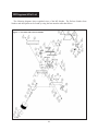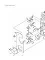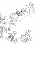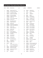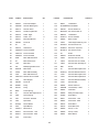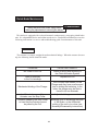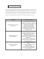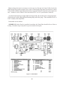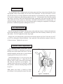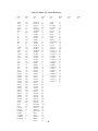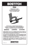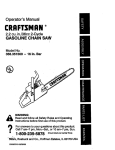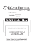
1
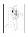
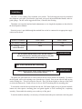
® DELUXE STITCHER C O M P A N Y I N C . solving your wire stitching needs for 125 years... Machine Serial Number : Head Serial Number : Date Purchased : Model M2 Stitchers OPERATION AND MAINTENANCE MANUAL M2-AST Stitcher...with 26D Head....115V and 60HZ M2-BST Stitcher...with 26D Head....230V and 50HZ M2G8-AST Stitcher..with G8 Head...115V and 60HZ M2G8-BST Stitcher..with G8 Head...230V and 50HZ Before using this Stitcher, all operators must study this manual and follow the safety warnings and instructions. Keep these instructions with the M2 Stitcher for future reference. If you have any questions, contact your local DeLuxe Stitcher Graphic Arts Representative or Distributor. WARNING! Model M2 Stitchers Operators and others in the work area should always wear safety glasses to prevent serious eye injury from fasteners and flying debris when loading, operating, or unloading this machine. Do not operate this stitcher without all guards in place. The stitcher will not operate without the front guard closed properly. Do not modify the guards in any way. Always disconnect the power supply before removing any guards for servicing. Never operate the machine with wire feeding through the head unless there is stock above the clinchers, otherwise serious damage may result. Always turn power off when making adjustments. Always disconnect the power supply before any disassembly work. 2 Table of Contents INTRODUCTION.....................................................................................................4 INSTALLATION.......................................................................................................6 Belt Guard Removal and Assembly................................................6 Turning Machine Manually..............................................................7 OPERATING ADJUSTMENTS................................................................................7 Adjusting the Machine for Thickness of Work................................7 Raising or Lowering the Clinchers..................................................9 MAINTENANCE.....................................................................................................10 Lubrication.....................................................................................10 M2 DIAGRAM & PARTS LIST................................................................................11 CLUTCH-BRAKE MAINTENANCE........................................................................16 Actuator.........................................................................................16 Clutch and Brake Springs..............................................................17 Disassembly..................................................................................18 Assembly.......................................................................................18 Lubrication.....................................................................................20 Coil Replacement..........................................................................20 Control Collar Adjustment..............................................................20 ITEM / INDEX NUMBER CROSS-REFERENCE...................................................21 NOTES .......................................................................................................22 WARRANTY AND SERVICE INFORMATION........................................................23 3 Introduction The DeLuxe Stitcher M2 Book Stitcher is a combination light & heavy duty stitcher designed to staple both flat and saddle work ranging in thickness from a few sheets to 1/4" for 2601 heads, 5/16" (8mm) for G8 heads. The recommended wire sizes to be used on the M2 are as follows: 25 to 30 round wire for 2601 heads, 24 to 28 for G8 heads. The M2 is easily adjusted from saddle work to flat work by means of tilting the 5-1/2" (14cm) x 26" (66cm) work table. An adjustable work guide and adjustable work stops are easily attached to the work table and provide for accurate registering of flat work for uniform spacing of staples. The M2 is footswitch operated and is belt driven by a 1/2 HP motor, making possible operating speeds up to 215 stitches per minute. The motor is mounted on an adjustable bracket which can be raised or lowered for adjusting the driving belt tension. The machine driving mechanism is thoroughly shielded thus preventing the possibility of personal injury. The M2 has a 14" (35.6cm) throat depth for both flat and saddle stitching. The work table is approximately 34" (86.4cm) above the floor, and there is approximately 17/32" (24mm) clearance between the top of the work table and the stitching head. The M2 weighs approximately 325 lb (145 kgs) net, shipping weight is approximately 3 80 lb (I 72 kgs). With the table installed, the M2 requires about 28" (71.1 cm) x 30" (76.2cm) of floor space. Because of the length of the work table, the M2 must be secured to the floor to meet CE stability requirements. Sound level readings at the normal operator position are approximately 84 dBC. 4 Figure 1 - M2 Stitcher 5 Installation The M2 is a free standing, floor mounted, wire stitcher. The following parts must be assembled after shipment: work table, spool bracket, spool stud, wire spool, adjuster handwheel handle, and wire guide springs. The M2 can be lagged to the floor, if desired, after leveling. Thread the wire onto the head and make adjustments to wire length & straightness as described in the head Operation Manual. Electrical power is provided through the attached line cord to be connected to an appropriate supply outlet rated as shown: SUPPLY POWER 115V / 60HZ 230V / 50HZ M2 Rated Current 9.2A 4.6A M2 Interrupt Current, Internal Breaker 12kA 12kA Do not operate the M2 under power until the machine has been turned over manually (see below) to verify that the stitching heads are operating freely. ! WARNING Belt Guard Removal and Assembly Always disconnect the power supply before making any adjustments or servicing the stitcher. ! WARNING The plastic belt guard must first be removed before the M2 can be turned over manually. To remove the belt guard, remove the retaining screw from the top of guard. Press on one side tab while prying out the locking face. This will release the first tab. Next, pull down slightly on the top of the guard to release the bottom tab. Guard will now be free to lift off remaining tabs on mounting plate. To reassemble, interlock the top tab and one side tab. Pull down slightly on top of guard to interlock bottom tab, then squeeze mounting plate and guard together to lock remaining tab, completing assembly. Reassemble the retaining screw at the top of the guard. To turn the machine manually, it is necessary to first disconnect the power and remove the belt guard 6 Turning Machine Manually Always disconnect the power supply before making any adjustments or servicing the stitcher. ! WARNING (see above). Locate the actuator assembly on the wrap spring clutch and push the actuator to pivot it away from the control collar cam, releasing the brake. The machine will rotate one revolution when the large drive pulley is turned manually in the direction of the arrow on the pulley (top of pulley toward front of machine). Operating Adjustments The quality and quantity of work that can be stitched on the M2 is dependent upon the operator making the various operating adjustments as accurately as possible. The following information and instructions are provided so that the operator will clearly understand how to make the required operating adjustments. Adjusting the Machine for Thickness of Work (See Figure 2) Turn the thickness adjustment handwheel (1) clockwise until the gage spool (2) is raised sufficiently to allow a sample of work to be inserted between the gage spool and its lower stop. With the work held in this position, turn the handwheel (1) counter-clockwise until the work is firmly clamped between the gage spool (2) and the stop. Turn the handwheel back clockwise just enough to allow the work to be withdrawn from the gage, then return the handwheel to the setting at which the work was firmly clamped. 7 Figure 2 - Work Thickness Adjustment If the Machine is operated on work thicker than is set to handle, damage will result and the Stitcher will not operate properly. 8 ! CAUTION Raising or Lowering the Clinchers (See Figure 3) Always disconnect the power supply before making any adjustments or servicing the stitcher. ! WARNING If staples are being loosely clinched, requiring that the clinchers be raised or lowered, proceed as follows: Remove the clincher guard (1) . Loosen the clincher adjustment binder screw (2). Rotate the clincher adjustment screw (3) to raise or lower the clincher points as needed. Retighten the binder screw (2) and attach the clincher guard (1). Turn the machine over manually a few revolutions and ensure that the machine if operating freely before running under power. Figure 6 - Wire Straightening 9 Maintenance To insure continuous operation of the M2 Stitcher, the operator should be sure that the machine is regularly lubricated and carefully maintained. The operator should periodically inspect all moving parts for signs of wear and, when required, replace the worn parts. The following instructions are provided so that the operator will understand how to lubricate the machine, and how to adjust the clutch. Lubrication (See Figure 4) If the machine is operated on work thicker than it is set to handle, damage will result. ! WARNING Use an S.A.E. No. 10 oil for lubricating the M2 Stitcher. Machines that are in constant use should be lubricated daily. Machines that are operated periodically should be lubricated just prior to use. Usually only a drop of oil is required at each lubrication point in the Stitcher. After lubricating the machine, wipe off any excessive oil. Refer to the stitcher head Operation Manual for additional lubrication points on each stitching head. Figure 4 - Lubrication Points 10 M2 Diagrams & Part List The following diagrams show exploded views of the M2 Stitcher. The DeLuxe Stitcher Item Number and description can be found by using the Item number table that follows. Figure A - Face Plate and Guard Assemblies 11 Figure B - Machine Assembly 12 13 Part Number / Description Cross-Reference ITEM NO. QTY DESCRIPTION QUANTITY INDEX ITEM NO. DESCRIPTION 1 G30001A Frame Weldment 1 38 7676 Belt Guard 1 2 G30002 Side Cover Plate - Left 1 39 G30130 Adjuster Stud 2 3 G30006A Bearing Housing Assembly 1 40 P7507 Screw 1/4-20x3/4 1 4 G30007B Crank Shaft Assembly 1 41 PW14.6 Washer 1 5 G30011A Adjuster Lever Assembly 1 42 LW14 Lock Washer 1 6 G30017A Pivot Link Assembly 1 43 PW38 Washer 1 7 G30020A Upright Link Assembly 1 44 HN3816 Hex Nut 3/8-16 1 8 G30031B Adjuster Fork 1 45 UA6112.1 Screw 3/8-16x3/4 1 9 G30041A Clincher Roller Assembly 2 46 PW10.3 Flat Washer 3/16 1 10 G30043B Clincher Lever 1 47 UA3806.9 Screw 10-32x3/8 1 11 G30048 Motor Mounting Plate 1 48 UA5112.1 Screw 5/16-18x3/4 1 12 G30049 Dowel Pin 5/8x2-1/2 1 49 PW516 Washer 2 13 G30067 Bolt 3/8-16x1 1 50 HN51618 Hex Nut 5/16-18 1 14 G30099B Adjustment Crank Housing 1 51 P7863 Retaining Ring 1 15 G30100B Adjuster Crank Shaft Insert 1 52 UA4812.1 Screw 1/4-20x3/4 1 16 G30101 Adjuster Yoke 1 53 UA4810.5 Screw 1/4-20x5/8 1 17 G30102 Adjuster Shaft Screw 1 54 UA4810.1 Screw 1/4-20x5/8 1 18 G30103 Adjuster Stop 1 55 UA4808.3 Screw 1/4-20x1/2 1 19 G30117B Motor Cover 2 56 PW12 Washer Zinc 1/2 1 20 G30118 Belt Guard Bracket 1 57 CB837E Retaining Ring 1 21 G30127 Starter Mounting Flange 1 58 UA3808.1 Screw 10-32x1/2 1 22 G30128 Hand Wheel 1 59 PW10 Washer 2 23 FC9632 Anchor Spacer 1 60 LW10 Lock Washer 1 24 FC9656 Clutch Anchor 1 61 UA4816.1 Screw 1/4-20x1 1 25 UA8164 Screw 1/2-13x4 1 62 PW14 Flat Washer 1 26 HN1213.2 Hex Jam Nut 1/2-13 1 63 HN1420 Nut 1/4-20 1 27 7681 Screw Clutch Anchor 1 64 G30013A Drive Lever Assembly 1 28 SW14 Lock Washer 1 65 G30014 Slider Pin 1 29 HN1420.5 Hex Nut 1/4-20 2 66 G30016 Slider 1 30 850730 V-Belt 1 69 G30037A Clincher Upright Link Asy 1 31 35 Clincher Slide Link Spring 1 70 G30005A Crank Throw Assembly 1 32 406 Cl. Op. Lever Spring Screw 1 73 G30027 Face Plate Adapter 2 33 G30061 Shoulder Screw 1/2x1-1/2 1 74 G30028 Slider Guide 1 34 G30063 Shoulder Screw 5/8x1 1 75 G30029 Slider Guide Screws 1 35 G30064 Shoulder Screw 3/4x1-1/4 1 76 G30030B Adjuster Slide 1 36 G30065 Screw 1/2x1 1 77 G30097 Adjuster Pivot Pin 1 37 7675 Belt Guard 1 78 G30032 Adjuster Plate 1 14 ITEM NO. DESCRIPTION QUANTITY INDEX ITEM NO. DESCRIPTION QTY 80 G30152 Adjuster Spool 1 126 UA4812.7 Screw 1/4-20x3/4 1 81 G30034 Drive Plate Adapter 1 127 SW14.1 Lock Washer 2 82 G30044A Clincher Mounting Asy 1 130 SU-0308853Screw 3/8X3/8 1 83 G30113 Clincher Guard 1 135 G30159 1 84 G30124 Actuator Key Bracket 2 137 HN51618.2 Hex Jam Nut 5/16-18 1 85 G30142 Guard - Right 1 138 SW516.2 Lock Washer 1 86 G30143 Guard - Left 11 139 UA3410.4 Screw 10-32x5/8 1 87 G30157 Wire Spool Bracket 1 147 850300 Motor 1/2 HP 1 88 HN1024 Nut 10-24 1 149 7645A Table Support Brkt Asy - RH 1 90 36 Pin 1 150 UA5120.2 Screw 5/16-18x1-1/4 1 91 G30145 Head Guard 1 151 UA4828.3 Set Screw - Cup Point 1 92 UA3806.16 Screw 1/4-20x3/8 1 152 HN1420.2 Hex Jam Nut 1/4-20 2 93 UA3812.2 Screw 10-32x3/4 1 154 29 Dowel 1 94 UA3806.3 Screw 10-32x3/8 1 155 G20243 Dowel Pin 1/4x9/16 1 96 203B Work Table Swivel Pin 2 156 7024B Clincher Point 1/2 - Flat 1 97 63 Work Guide Screw 1 or 7257B Clincher Point 1/2 - Round 1 98 7423 Work Stop 1 157 7253A Clincher Plate Assembly 1/2 1 99 425 W/G Spring Holder Screw 1 158 9081 Screw 1 100 M7201B Work Guide 1 159 38 Clincher Slide Adjust Screw 2 101 7656A Work Table Assembly 1 160 UA3216.2 Clincher Slide Block Screw 1 102 7056 Work Table Extension 1 161 18186 Clincher Slide Adjust Screw 1 103 UA3810.10 Shoulder Screw 1/4x5/8 1 162 18183 Clincher Slide Adjust Block 1 104 7648 Table Support 2 163 18184 Clincher Slide Block Clamp 1 105 HN1032 Nut 10-32 1 164 18182 Clincher Slide 1 106 850696 Pulley 1 200 850302 Starter Enclosure 1 106 850738 Pulley 1 201 850303B Terminal Strip - Holes 1 107 B554 Torsion Spring 1 202 850304 Footswitch 1 108 38 Clincher Slide Adjust Screw 1 203 850308 Safety Interlock Switch 1 112 7690 Tension Spring 1 204 851005 Strain Relief 2 113 7691 Set Collar - Reamed 1 205 86243 Power Cord - 115V 1 114 7693 Spool Stud 1 205 850307 Power Cord - 230V 1 115 M11009 Plastic Washer 1 206 850314 Strain Relief 1 116 2245 Spool Washer 2 207 850315 Strain Relief Nut 1 117 PG10271 Washer 9/16 1 208 850305 UV Trip - 115V 1 124 850673 Electric Clutch - 115V 1 208 850306 UV Trip - 230V 2 124 850674 Electric Clutch - 230V 1 209 850301 Motor Starter 1 125 7678 Drive Pulley 1 15 Screw 1/2-20x1-1/4 Clutch-Brake Maintenance Always disconnect the power supply before making any adjustments or servicing the stitcher. ! WARNING This stitcher is equipped with a solenoid actuated, continuous trip, wrap spring clutch-brake unit. It is a dependable device and seldom needs service. But should a malfunction occur, the following information is a service and troubleshooting guide for maintenance of this unit. Actuator The actuator is a simple, straight-forward mechanical linkage. When the actuator does not trip, the following checks should be made: PROBLEM CAUSE AND REMEDY No Power to the Coil Lack of continuity in the Coil windings Mechanical binding of the Plunger Insufficient clearance of the Actuator over the Stop Collar Actuator loaded by the Stop Collar so hard that the Actuator cannot be pulled by the Coil 16 Check all wiring and switching in the Clutch Actuation System Replace the Coil The Coil may have shifted, or the Plunger end may have mushroomed due to striking the backstop. In the latter, the plunger may be filed or turned to its true diameter Adjust the linkage as needed Breaking force is exceeding the limits of the Brake, or the differential setting of the unit is too close (see Assembly/Disassembly instructions) Clutch and Brake Springs With the brake engaged (full limit of output), the input hub should be free to rotate by hand. With the clutch engaged, the input and output hubs should rotate together. If the unit does not rotate in either of these modes, the clearance between the hubs of the unit on the shaft may have been disturbed or damaged. See Assembly/Disassembly instructions for re-adjusting. Listed below are additional checks to be made if the clutch does not function correctly: PROBLEM Clutch Brake does not drive but Input turns Clutch-Brake jams and stalls Input Motor Output does not repeat stopping point CAUSE AND REMEDY A. Drive Spring may be broken at crossover point from an overload caused by a jam. Replace Spring and check Hubs for damage. B. Collar may not snap forward because of foreign matter restricting movement. Clean unit. C. Actuator does not pull in. See Actuator section. A. Spring tang broken off Drive Spring, not allowing Clutch to disengage while Brake is engaged. Replace Drive Spring. B. Clutch output bound up. Check clearance between Output Hub and Brake Hub. C. Completely out of adjustment caused by losing an internal Spring Tang. Replace Spring. A. Not enough inertia to actuate brake. B. Tang broken off Brake Spring, replace SPring. C. Adjust Collar Locking Screw, may be loose allowing Adjusting Screw to rotate. 17 Disassembly (See Figure 5) Always disconnect the power supply before making any adjustments or servicing the stitcher ! WARNING To disassemble the clutch-brake unit (124) it will first be necessary to remove the drive pulley (125) from the stitcher by removing the V-belt (30), retaining ring (51), and clutch anchor screw (27). Disconnect the ground and solenoid wires, and swing the anchor strap (24) clear of the drive pulley assembly and slide it off of the drive shaft. Remove the three screws (126) connecting the drive pulley to the clutch-brake unit. When disassembling the clutch-brake unit, always mark the spring tang locations with reference to which slots they go in if the same springs are to be used for reassembly. To disassemble the clutchbrake unit, proceed as follows: Release Actuator Lever so that clutch is engaged and brake released. Remove Retaining Ring and Shim Washer, if any, from the input Hub end. Remove input Hub by rotating opposite to the drive direction. Remove Retaining Ring and Shim Washer, if any, from the Mounting Plate end. Remove Output Shaft Springs and Control Collar assembly by rotating Output Shaft in the drive direction (DO NOT DISASSEMBLE BRAKE HUB FROM MOUNTING PLATE). Remove Control Collar from the Output Shaft and Spring assembly by extracting toward the Brake Spring end. Assembly (See Figure 5) Replace Clutch, Brake and Anti-Backup Springs as required. Assemble Springs concentric and square to the Output Shaft. Assemble Control Collar over the Output Shaft and Spring assembly by inserting from the Brake Spring end (it will be necessary to extend Brake Spring using long nose pliers). Place the Brake Spring tang in any one (1) of the nine (9) Control Collar slots at random. Assemble Output Shaft, Springs, and Control Collar assembly to the Mounting Plate assembly by rotating Output Shaft in the drive direction. Assemble Retaining Ring to Output Shaft at the Mounting Plate end (smooth surface facing Brake Hub). Check end play between Hub and Retaining Ring with feeler gauge. There should be 0.004" to 0.010" end play. Use Shim Washer to adjust. Rotate Output Shaft in the drive direction until it reaches a full brake position. With the Clutch Spring Tang not in slot, insert the Input Hub by rotating opposite to the drive direction. Select the one (1) of ten (10) Control Collar slots for the Clutch Spring Tang that will provide a 0.38" to 0.50" circumferential overtravel of the Control Collar when released. 18 Note: At this point it may be necessary to reselect one (1) of the nine (9) Control Collar slots for the Brake Spring Tang (release Actuator Lever, remove Clutch Spring Tang from slot, then move Control Collar axially toward the Input Hub end and rotate it opposite to the drive direction to pick up the next slot). Continue to select Control Collar slots until the 0.38" to 0.50" specification is achieved. Assemble Retaining Ring to Output Shaft at the Input Hub end (smooth surface facing Input Hub). Check end play between Input Hub and Retaining Ring with feeler gauge. There should be 0.002" to 0.003" end play on the Input Hub. Reassemble unit to machine. IMPORTANT: After Clutch is assembled to machine, the Clutch Plate should be free to float on bearing - the anchor strap is only there to prevent rotation of the plate. Figure 5 - Clutch-Brake 19 Lubrication The clutch-brake unit is designed with the bearing parts made from sintered metal that has been impregnated with oil and normally do not need to be re-lubricated. In cases where there is severe duty, the unit may be re-oiled or flushed out with minimal or no disassembly by using a light bearing oil as used in manufacture (Shell Bearing Infusion Oil #33). If disassembly of the unit for cleaning and oiling is necessary, follow the detailed disassembly instructions to the point needed, flush and wipe parts in the oil to be used for re-lubrication. DO NOT USE SOLVENT to clean the parts. To get more cleaning action for the oil, it may be heated while cleaning the components, but bring the parts back to ambient temperature submerged in cool oil. Coil Replacement Place the Spring onto the Plunger with the narrow end towards the Actuator. Slide the Solenoid onto the Actuator and Plate Assembly. Assemble the Solenoid to the Plate Assembly with the cap screws and washers. DO NOT tighten more than finger tight. Energize the Coil and adjust the gap between the Actuator and the top of the Collar Stop to 0.015" to 0.030" by sliding the Solenoid assembly. Note: push the Collar toward the Actuator to allow for Collar movement. Tighten the cap screws. Control Collar Adjustment The stopping position of the head can be changed if necessary by adjusting the position of the stop cam on the control collar sleeve. Turn the machine manually until the driver is in the desired stopping position, the proceed as follows: Work Retaining Ring "A" out of its groove and slide it forward on Sleeve "C". Slide Cain "B" off Splines, rotate to align Collar Stop with Actuator and slide the Cam back on the Splines. The Actuator Prawl will have to be held clear during this operation. Slide the Retaining Ring back into its groove. Note: Make sure brake is locked up before proceeding to insure getting the proper stop point. Figure 6 - Clutch-Brake 20 Item No. Index No. Cross-Reference Item IndexItem Index Item Index Item No. No. No. No. No. No. No. 18182 164 18183 162 18184 163 18186 161 203B 96 2245 116 29 154 35 31 36 90 38 159 38 108 406 32 425 99 63 97 7024B 156 7056 102 7253A 157 7423 98 7645A 149 7648 104 7656A 101 7675 37 7676 38 7678 125 7681 27 7690 112 7691 113 7693 114 850300 147 850301 209 850302 200 850303 201 850304 202 850305208 850306208 850307205 850308203 850314206 850315207 850673124 850674124 850696106 850730 30 850738 106 851005 204 86243 205 9081 158 B554 107 FC963223 FC9656 24 G30001A 1 G300022 G30005A70 G30006A3 G30007B4 G30011A5 G30013A64 G30014 65 G30016 66 G30017A6 G30020A7 G3002773 G3002874 G3002975 G3003076 G300318 G30032 78 G3003481 G30037A69 G30041A9 G30043 10 G30044A82 G30048 11 G30049 12 G30061 33 G30063 34 G30064 35 G30065 36 G30067 13 G30097 77 G30099 14 G30100 15 G30101 16 G30102 17 G30103 18 G30113 83 G30117 19 G30118 20 G3012484 G3012721 G3012822 G3013039 G3014285 G3014386 G3014591 G3015280 G3015587 HN102488 HN1032105 HN1213.226 HN142063 HN1420.2152 HN1420.529 HN381644 HN5161850 HN51618.2137 LW10 60 LW14 42 M11009 115 M7201 100 P750740 P7863 51 P8054 57 PG 10271 117 PG 10512 135 PW10 59 PW10.3 46 PW12 56 PW14 62 PW14.6 41 PW38 43 PW516 49 SU-0308853130 SW14 28 SW14.1 127 SW516.2 138 UA3216.2160 UA3410.4 139 UA3806.1692 UA3806.394 UA3806.947 UA3808.158 UA3810.10103 UA3812.293 UA4808.355 UA4810.154 UA4810.553 UA4812.152 UA4812.7126 UA4816.161 UA4828.3151 UA5112.148 UA5120.2150 UA6112.145 UA8164 25 21 Index No. NOTES 22 LIMITED WARRANTY DeLuxe Stitcher Company warrants to the original retail purchaser that this product is free from defects in material and workmanship and agrees to repair or replace, at DeLuxe Stitcher’s option, any defective product within 90 days from the date of purchase. This warranty is not transferable. It covers damage resulting only from defects in material or workmanship and does not cover conditions or malfunctions resulting from normal wear, neglect, abuse or accident. This warranty is in lieu of all other express warranties. Any warranty of merchantability or fitness for a particular purpose is limited to the duration of this warranty. DeLuxe Stitcher shall not be liable for any incidental or consequential damages. Some states do not allow limitations on how long an implied warranty lasts, or the exclusion or limitation of incidental or consequential damages, so the above limitations or exclusions may not apply to you. This warranty gives you specific legal rights and you may also have other rights which vary from state to state. To obtain warranty service you must return the product, at your expense, together with proof of purchase to an authorized DeLuxe Stitcher Company Graphic Arts Dealer. Always use genuine DeLuxe Stitcher parts. When ordering parts, please identify the part number, the part name, the wire size and crown size of your Stitcher. DeLuxe Stitcher Company, Inc. Chicago, Illinois 60634-2410 Phone: 773-777-6500 800-634-0810 Fax: 773-777-0156 800-417-9251 E-mail: [email protected] Web Site: http://www.deluxestitcher.com 23 ® DELUXE STITCHER ISP Stitching & Bindery Products C O M P A N Y 3747 Acorn Lane • Franklin Park • Illinois 60131 Phone: 847-455-4400 • 800-634-0810 Fax: 847-455-4900 • 800-417-9251 http://www.deluxestitcher.com DBSM2 - 0415 I N C .