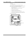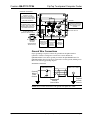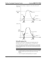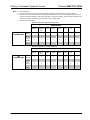
1
Crestron QM-FTCC-TPS4 FlipTop Touchpanel Computer Center Operations & Installation Guide This document was prepared and written by the Technical Documentation department at: Crestron Electronics, Inc. 15 Volvo Drive Rockleigh, NJ 07647 1-888-CRESTRON All brand names, product names and trademarks are the property of their respective owners. ©2005 Crestron Electronics, Inc. Crestron QM-FTCC-TPS4 FlipTop Computer Center Contents FlipTop Touchpanel Computer Center: QM-FTCC-TPS4 1 Introduction ..........................................................................................................1 Features and Functions...........................................................................1 QuickMedia Transport System...............................................................3 Specifications .........................................................................................5 Physical Description...............................................................................6 Industry Compliance ............................................................................12 Setup...................................................................................................................12 Network Wiring ...................................................................................12 QM Network Wiring ............................................................................13 Crestron Toolbox .................................................................................13 Identity Code........................................................................................13 Installation............................................................................................15 Hardware Hookup ................................................................................20 Ground Wire Connections....................................................................21 Configuring the Touchpanel.................................................................22 Programming Software.......................................................................................24 Earliest Version Software Requirements for the PC......................................25 Programming with SystemBuilder .......................................................25 Programming with SIMPL Windows...................................................26 Example Program.................................................................................28 Programming with VT Pro-e................................................................28 Adjusting the QM-FTCC-TPS4 Microphone Inputs ............................29 Uploading and Upgrading ..................................................................................32 Communication Settings ......................................................................32 Uploading a SIMPL Windows Program ..............................................35 Firmware Upgrade ...............................................................................37 Problem Solving .................................................................................................40 Further Inquiries...................................................................................41 Future Updates .....................................................................................41 Appendix A: International Receptacles ..............................................................42 Appendix B: QuickMedia Installation and Compensation .................................43 Installation Notes .................................................................................43 Compensation.......................................................................................43 Compatibility Charts ............................................................................45 Return and Warranty Policies.............................................................................47 Merchandise Returns / Repair Service .................................................47 CRESTRON Limited Warranty ...........................................................47 Operations & Installation Guide – DOC. 6393 Contents • i Crestron QM-FTCC-TPS4 FlipTop Computer Center FlipTop Touchpanel Computer Center: QM-FTCC-TPS4 Introduction Features and Functions The QM-FTCC-TPS4 FlipTop Touchpanel Computer Center is part of the Crestron MediaManager line of network devices, room control systems and signal routing solutions. The unit comprises two separate devices: a touchpanel and a QuickMedia transmitter, housed in the same mechanical enclosure. The built in TPS-4 touchpanel is a compact Crestron 3.6-inch touchpanel that provides user interface to a Crestron® remote control system (Cresnet® system). Although the units share the same Cresnet connection, they appear as two separate devices on the network, and have no local interaction. Functional Summary • • • • • • • • • • • • • • • Built-in touchpanel with ten hardkeys* 3.6 in (9.15 cm) active color matrix display 320x240 screen resolution 96MIPs ColdFire processor running Crestron Isys® generation firmware 16-bit, non-palette graphics 64,000-color Crestron Isys engine 8 MB of flash (approx. 7MB for user display lists) 16 MB of DRAM (Dynamic RAM) for panel firmware One AC power passthrough One computer RGB connector with component video detect and auto sync sensing One computer audio connector One RJ-45 Ethernet port Two MIC inputs with phantom power and line level inputs One QuickMedia RJ-45 connector Two Cresnet connectors * As an option, a custom-engraved bezel can be designed and obtained by using the Crestron Engraver software. Version 2.4 and Crestron Database 17.4 or later are available from the Crestron website (www.crestron.com). The bright 3.6" active-matrix color touchscreen provides a fully customizable user interface for control of AV, lighting, screens, volume and more. With 16-bit Isys Operations & Installation Guide – DOC. 6393 FlipTop Touchpanel Computer Center: QM-FTCC-TPS4 • 1 FlipTop Touchpanel Computer Center Crestron QM-FTCC-TPS4 graphics, the QM-FTCC-TPS4 produces astounding 3D graphics, dynamic text, and full-motion animations complete with WAV file audio feedback. Ten programmable pushbuttons are also included featuring translucent buttons with white LED backlighting and an engravable faceplate. An AC power outlet is provided along with supplied pull-out VGA and audio cables for easy connection of laptops and computers. Video sensing and auto switching features provide seamless presentation display upon connection. All inputs and cabling are hidden beneath the table surface and stowed neatly within the FlipTop compartment. Excess cable simply drops out-of-sight below the box through silkscreen labeled, grommeted holes in the bottom plate. A LAN slot is provided in the bottom plate to permit the inclusion of any third-party cable for network connectivity. Two gated microphone inputs are included via terminal block connectors located below the table surface. A wide-range of microphones is supported including dynamic and condenser type, as well as balanced or unbalanced line-level sources such as wireless microphones. To prevent any inadvertent screen presses, the QM-FTCC-TPS4 disengages the touchpanel whenever the lid is not fully opened. The QM-FTCC-TPS4 mounts flush to any tabletop, concealing all cables and connectors, providing a clean professional appearance to any conference room or classroom. Complete MediaManager systems can be configured easily for a variety of applications using Crestron SystemBuilder™ software. The QM-FTCC-TPS4 uses QuickMedia™ technology to facilitate an uncomplicated connection of audio, video, and computer equipment. All media and control signals are routed via a single QuickMedia cable for simple installation. A complete integrated room solution is created with the addition of a QuickMedia receiver (such as the QM-RMCRX-BA) and optional keypads or touchpanels. The QM-FTCC-TPS4 is available in four different models. Models DESCRIPTION Domestic Models International Models MODEL NUMBER COLOR QM-FTCC-TPS4-B Black QM-FTCC-TPS4-BALUM Brushed Aluminum QMI-FTCC-TPS- B Black QMI-FTCC-TPS- BALUM Brushed Aluminum The international models accommodate a wide variety of international AC adaptors. For simplicity within this guide, the color suffix and international designation are omitted and QM-FTCC-TPS4 is used except where noted. NOTE: The QM-FTCC-TPS4 is compatible with 2-Series control systems only. 2 • FlipTop Touchpanel Computer Center: QM-FTCC-TPS4 Operations & Installation Guide - DOC. 6393 Crestron QM-FTCC-TPS4 FlipTop Touchpanel Computer Center QM-FTCC-TPS4 Block Diagram Touchpanel & Buttons A/D Converter Computer Audio AC Power RJ-45 Ethernet QM Output Cresnet A/D Converter MIC 1 MIC 2 Program L Program R Video Microphone 2 Phantom Power Input Gain Microphone 1 AC Power Video Sync Sensing Computer RGB QuickMedia Transport System Using a proprietary signal routing solution, signals such as RGBHV, audio, and microphone are all transported using a single cable solution called QuickMedia (QM). The QM transport system port is capable of managing computer, video, and audio signals simultaneously through one CresCAT-QM cable, simplifying installations. Routing CresCAT-QM cable is less expensive and much simpler than routing multicolored, multi-conductor coax cable. All Crestron products using the QM transport system are capable of sending and receiving QM signals via CresCAT-QM cable. Installation of any QM device is as simple as installing one set of QM wires from output to input. Installations are flexible, affordable, and fast. The Crestron QuickMedia cable “CresCAT-QM” contains one low-skew CAT5E cable and one Cresnet® cable in siamese jackets. Operations & Installation Guide – DOC. 6393 FlipTop Touchpanel Computer Center: QM-FTCC-TPS4 • 3 FlipTop Touchpanel Computer Center Crestron QM-FTCC-TPS4 CresCAT-QM Cable NOTE: Do not untwist the two wires in a single twisted pair for more than 1/3-1/2" (0.84 – 1.27 cm) when making a connection. The twists are critical to canceling out interference between the wires. The QuickMedia transport mechanism performs delay compensation on each video input to compensate for signal skew, and frequency/bandwidth compensation for cable length. Signal skew occurs when part of the signal is delayed with respect to other signal components. The amount of skew largely depends on the length and design of the wire. Because CAT5 consists of twisted pairs that are twisted together in the cable, unequal wire lengths are created. The maximum aggregate cable length from QM transmitter to QM receiver is limited by the loss of bandwidth over long distances and the amount of available skew compensation. A cable rated at 22 ns (nanoseconds) of skew per 100 meters (328 ft.) means that a cable will have no more than a 22 ns difference between the fastest and slowest RGB signals over 100 meters of cable. To determine the allowable maximum length of installed cable, the installer must first perform a calculation based on the skew rating of the cable. The use of lowresolution signals may allow increased cable length but must be tested with the sources to be used. To ensure sufficient bandwidth to support signal resolutions up to 1600 x 1200, the maximum aggregate cable length should not exceed 328 feet. Skew compensation is primarily relevant to RGB sources; however, any/all video or VGA signals may experience a loss of quality over very long lengths of cable. This phenomenon is due to the added resistance and capacitance of longer cable lengths, and is not particular to either Crestron and/or QuickMedia systems. The total accumulated skew from QM transmitter to QM receiver must not exceed 22 ns. Crestron recommends a cable with a rating of less than or equal to 22 ns over its entire length. For example, if using a cable with a rating of 22 ns/100 meters (100 meters = 328 feet), connecting the QM-FTCC-TPS4 transmitter with 150 feet of cable to a QM-MD7x2 switcher, and then using another 150 feet to connect the QMRMCRX-BA receiver, the accumulated skew over the entire 300 feet should not exceed 22 ns. 4 • FlipTop Touchpanel Computer Center: QM-FTCC-TPS4 Operations & Installation Guide - DOC. 6393 Crestron QM-FTCC-TPS4 FlipTop Touchpanel Computer Center Specifications Specifications for the QM-FTCC-TPS4 are given in the following table. QM-FTCC-TPS4 Specifications SPECIFICATION DETAILS Cresnet Power Usage 13 Watts (0.54 Amp @ 24 VDC) Default Network ID QM Module Touchpanel 1A 03 Video Formats RGBHV (VGA), RGsB, RGBS, YPBPR Video Detection Within 2 seconds Firmware QM Module Touchpanel qm-ftcc-tps4-3.12.upg or later tps4_qm-ftcc-tps-tps4_c2n-ft-tps4_2.007.0161.upg or later 2-Series Control System 1,2 Update Files Version 3.150.CUZ (for QM-RMCRX-BA) or later Connectors Computer Input (1) DB15HD female, video sensing on H-sync, component sensing (G/Y) Computer Audio (1) 3.5mm mini-jack, computer soundcard type QuickMedia Output (1) RJ-45 CAT5E/CAT6 Cresnet (2) 4-pin terminal blocks Ground (1) Ground Terminal Microphone (2) 5-pin terminal blocks Touchpanel Display Display Type Size Resolution Colors Illumination Contrast ratio Viewing angle Touchscreen Active matrix color LCD 3.6 in (9.1 cm) 320 x 240 pixels maximum 64,000 (16 bits) LED 300 cd/m² 300:1 typical ±80° typical horizontal, +80°/-50° typical vertical Resistive membrane Touchpanel Processor CPU Processing Speed 32-bit Freescale Coldfire MCF5270 Microprocessor 96 MIPS Touchpanel Memory 8MB internal flash; 16MB DDR RAM Touchpanel Ethernet Support 10/100Base-T Full duplex, Link and Activity LEDs Dimensions and Weight (Domestic Models) Width: 7.67 in (19.49 cm) Height: 5.67 in (14.40 cm) Depth: 6.55 in (16.64 cm) Weight: 4.05 lbs (1.84 kg) Dimensions and Weight (International Models) Width: 8.91 in (22.64 cm) Height: 5.67 in (14.40 cm) Depth: 7.52 in (19.10 cm) Weight: 4.80 lbs (2.18 kg) Operating Temperature and Humidity 41º to 104º F (5º to 40º C) 10 to 90% relative humidity (non-condensing) International Adaptors for QMI-FTCC-TPS4 Models Refer to Appendix A on page 42 1. The latest software versions can be obtained from the Crestron website. Refer to the NOTE following these footnotes. 2. Crestron 2-Series control systems include the AV2 and PRO2. Consult the latest Crestron Product Catalog for a complete list of 2-Series control systems. Operations & Installation Guide – DOC. 6393 FlipTop Touchpanel Computer Center: QM-FTCC-TPS4 • 5 FlipTop Touchpanel Computer Center Crestron QM-FTCC-TPS4 NOTE: Crestron software and any files on the website are for Authorized Crestron dealers and Crestron Authorized Independent Programmers (CAIP) only. New users may be required to register to obtain access to certain areas of the site (including the FTP site). Physical Description Refer to the physical views shown below and on subsequent pages. QM-FTCC-TPS4 Open View QM-FTCC-TPS4 Physical Dimensions – Top View 7.67 in (19.49 cm) 6.00 in (15.24 cm) QMI-FTCC-TPS-4 Physical Dimensions – Top View 8.91 in (22.64 cm) 7.24 in (18.39 cm) 6.55 in (16.64 cm) 6 • FlipTop Touchpanel Computer Center: QM-FTCC-TPS4 7.52 in (19.10 cm) Operations & Installation Guide - DOC. 6393 Crestron QM-FTCC-TPS4 QM-FTCC-TPS-4 Physical Dimensions - Front View FlipTop Touchpanel Computer Center QMI-FTCC-TPS-4 Physical Dimensions - Front View 6.28 in (15.96 cm) 7.51 in (19.08 cm) 7.17 in (18.22 cm) 8.41 in (21.35 cm) QM-FTCC-TPS4 Bottom View Operations & Installation Guide – DOC. 6393 QMI-FTCC-TPS4 Bottom View FlipTop Touchpanel Computer Center: QM-FTCC-TPS4 • 7 FlipTop Touchpanel Computer Center QM-FTCC-TPS4 Physical Dimensions - Back View Crestron QM-FTCC-TPS4 QMI-FTCC-TPS4 Physical Dimensions - Back View 3.43 in (8.71 cm) 2.75 in (6.99 cm) 0.09 in (0.23 cm) 0.09 in (0.23 cm) 4.66 in (11.84 cm) 4.66 in (11.84 cm) 5.67 in (14.40 cm) QM-FTCC-TPS4 Physical Dimensions - Side View 5.67 in (14.40 cm) QMI-FTCC-TPS4 Physical Dimensions - Side View BROWN, BLUE, AND GREEN W/YELLOW STRIPE WIRE LEADS 5.51 in (14.0 cm) 6.05 in (15.37 cm) 8 • FlipTop Touchpanel Computer Center: QM-FTCC-TPS4 6.48 in (16.46 cm) 7.02 in (17.83 cm) Operations & Installation Guide - DOC. 6393 Crestron QM-FTCC-TPS4 FlipTop Touchpanel Computer Center Controls and Ports (Top) Buttons The QM-FTCC-TPS-4 touchpanel has 10 hard buttons; five on each side of the display. The buttons are backlit with white LEDs; brightness is program adjustable. The buttons can be programmed to automate frequently used functions. AC Outlet 125V – 50/60Hz 10A MAX 250V~50/60Hz 10A The 3-prong grounded AC outlet is rated 125 VAC @ 10 Amps, 50 – 60 Hz. The international version (QMI-FTCC-TPS-4) has a bezel that accepts an adaptor receptacle, and three wires that connect to the adaptor; blue, brown, and green with a yellow stripe. The international AC outlet is rated MAX 250 VAC @ 10 Amps, 50 – 60 Hz. Refer to “Appendix A” on page 42 for a complete list of international receptacles and applicable countries. Ports (Underside) MIC 1 / MIC 2 These two 5-pin 3.5 mm detachable terminal blocks provide two microphone and line level audio inputs. • Balanced microphone input level: -60 to –20 dBV nominal • Balanced line input level: -28 to +12 dBV, 4 VRMS maximum • Unbalanced input level: -34 to +6 dBV, 2 VRMS maximum • Microphone input impedance: 10 kΩ, accepts balanced microphones 60 to 600 Ω • Line input impedance: 22 kΩ (balanced), 11 kΩ (unbalanced) • Phantom power: 10 mA (total) at 48 VDC, software enabled for both inputs • Mic level indicators (via software): 20 dB below clipping (Norm), 6 dB below clipping (Overload) • Mic Input Gain: 0 to 100% (0 to 40 dB) plus mute • Gate level (threshold): 0 to 100% • Attack: 1 to 100 ms • Decay (release): 1 to 5000 ms • Analog to Digital conversion: 24-bit, 48 kHz AUDIO AUDIO This 3.5 mm mini-jack is provided for the computer sound card output. The connector provides an unbalanced stereo line-level audio input (maximum input level 1 VRMS @ 10 kΩ). Operations & Installation Guide – DOC. 6393 FlipTop Touchpanel Computer Center: QM-FTCC-TPS4 • 9 FlipTop Touchpanel Computer Center Crestron QM-FTCC-TPS4 QM 8 This eight-pin RJ-45 transport port allows connection of the QuickMedia cable. It carries audio, video, and microphone signals over CresCAT-QM cable to a QuickMedia receiver or switcher. For more information on QuickMedia refer to page 3. 1 RJ-45 QuickMedia Connector Pin Assignments RJ-45 PIN NUMBER WIRE COLORS (EIA 568B) 1 WHITE/ORANGE 2 3 4 BLUE + AUDIO 5 WHITE/BLUE - AUDIO 6 GREEN + RGB GREEN 7 WHITE/BROWN - RGB BLUE (- COMPOSITE) (-PB) 8 BROWN + RGB BLUE (+ COMPOSITE) (+PB) RJ-45 MALE CONNECTOR QM ASSIGNMENT RGB, COMPONENT, AND AUDIO - RGB RED (- CHROMINANCE) (-PR) ORANGE + RGB RED (+ CHROMINANCE) (+PR) WHITE/GREEN - RGB GREEN (- LUMINANCE) (-Y) (+ LUMINANCE) (+Y) NOTE: Always use CresCAT-QM cable to make QuickMedia connections. NOTE: CresCAT-QM siamese cable includes four wires for making Cresnet connections. COMPUTER 5 1 6 10 15 11 COMPUTER This female DB15HD connector is used for connecting a computer’s RGB video output to the presentation system. This port can automatically detect the presence of an H-sync video signal to support RGBHV and RGBS, and component video detection by sensing the green video signal on pin 2 to support RGsB and Y, PB, PR. Refer to the following table for the DB15HD connector pin-assignments. • 75 Ω terminated (R, G, B) • Maximum input voltage 1 Vp-p • Maximum H and V Sync: 5.0 Vp-p into 1 kΩ RGB DB15HD Pin Assignments PIN FUNCTION PIN FUNCTION 1 Red Video 9 2 Green Video 10 Ground 3 Blue Video 11 No Connect 4 Reserved 12 Monitor Sense 1 5 Ground 13 Horizontal Sync 6 Red Ground 14 Vertical Sync 7 Green Ground 15 Monitor Sense 2 8 Blue Ground 10 • FlipTop Touchpanel Computer Center: QM-FTCC-TPS4 No Connect Operations & Installation Guide - DOC. 6393 Crestron QM-FTCC-TPS4 FlipTop Touchpanel Computer Center NET (x2) 24 Y Z G 24 Y Z G NET These two 4-pin terminal block connectors are for connection to the Cresnet network. One connector is used to connect to the Cresnet network while the second connector can be used to connect another Cresnet device. Cresnet power to the QM-FTCC-TPS4 is supplied through either of these connectors. For more information, refer to “Network Wiring” on page 12. AC Power Connect the six-foot (183 cm) grounded AC line cord to supply AC power to the outlet on the topside of the QM-FTCC-TPS4. 125V – 50/60Hz 10A MAX 250V~50/60Hz 10A The international version (QMI-FTCC-TPS4) is equipped with a standard IEC-320 electrical appliance coupler. The IEC (International Electrotechnical Commission) is the international standards and conformity assessment body for all fields of electrotechnology. LAN Green LED Yellow LED 8 1 An 8-wire RJ-45 connector with two LED indicators (green LED indicates link status, yellow LED indicates Ethernet activity). This connector provides an Ethernet 10baseT /100baseTX, full duplex, TCP/IP, UDP/IP, CIP, DHCP, IEEE 802.3U compliant network connection for the TPS4 touchpanel. LAN Connector Pinout PIN SIGNALS PIN SIGNALS 1 TX + 5 2 TX - 6 N/C RC - 3 RC+ 7 N/C 4 N/C 8 N/C Indicators (Underside) PWR (Power) This LED illuminates when 24 volts DC is supplied to the QuickMedia module from Cresnet. NET This LED illuminates when communication between the control system and the QuickMedia module is established (the QM unit is polled on the network). Illumination indicates that the SIMPL Windows program currently loaded has a network device defined at the same Net ID as the QM-FTCC-TPS4. SETUP LED and Pushbutton (Underside) The QuickMedia module is Touch-Settable ID-ready. A SETUP pushbutton is located on the bottom side of the QM-FTCC-TPS4. The SETUP pushbutton and its associated LED are used for setting the QuickMedia module’s network ID during the initial configuration of a Cresnet system or when the device is being added/replaced. Operations & Installation Guide – DOC. 6393 FlipTop Touchpanel Computer Center: QM-FTCC-TPS4 • 11 FlipTop Touchpanel Computer Center Crestron QM-FTCC-TPS4 Industry Compliance As of the date of manufacture, the QM-FTCC-TPS4 has been tested and found to comply with specifications for CE marking and standards per EMC and Radiocommunications Compliance Labelling. NOTE: This device complies with part 15 of the FCC rules. Operation is subject to the following two conditions: (1) this device may not cause harmful interference, and (2) this device must accept any interference received, including interference that may cause undesired operation. Setup Network Wiring CAUTION: In order to ensure optimum performance over the full range of your installation topology, Crestron Certified Wire, and only Crestron Certified Wire, may be used. Failure to do so may incur additional charges if support is required to identify performance deficiencies as a result of using improper wire. CAUTION: Use only Crestron power supplies for Crestron equipment. Failure to do so could cause equipment damage or void the Crestron warranty. CAUTION: Provide sufficient power to the system. Insufficient power can lead to unpredictable results or damage to the equipment. Please use the Crestron Power Calculator to help calculate how much power is needed for the system (http://www.crestron.com/calculators). When calculating the length of wire for a particular Cresnet run, the wire gauge and the Cresnet power usage of each network unit to be connected must be taken into consideration. Use Crestron Certified Wire only. If Cresnet units are to be daisychained on the run, the Cresnet power usage of each network unit to be daisychained must be added together to determine the Cresnet power usage of the entire chain. If the unit is a home-run from a Crestron system power supply network port, the Cresnet power usage of that unit is the Cresnet power usage of the entire run. The wire gauge and the Cresnet power usage of the run should be used in the following equation to calculate the cable length value on the equation’s left side. Cable Length Equation L< 40,000 RxP Where: L = Length of run (or chain) in feet. 2 R = 6 Ohms (Crestron Certified Wire: 18 AWG (0.75 MM )) P = Cresnet power usage of entire run (or chain). Make sure the cable length value is less than the value calculated on the right side of the equation. For example, a Cresnet run drawing 20 watts should not have a length of run more than 333 feet. NOTE: All Crestron certified Cresnet wiring must consist of two twisted pairs. One twisted pair is the +24V conductor and the GND conductor, and the other twisted pair is the Y conductor and the Z conductor. NOTE: When daisy-chaining Cresnet units, strip the ends of the wires carefully to avoid nicking the conductors. Twist together the ends of the wires that share a pin on the network connector, and tin the twisted connection. Apply solder only to the ends 12 • FlipTop Touchpanel Computer Center: QM-FTCC-TPS4 Operations & Installation Guide - DOC. 6393 Crestron QM-FTCC-TPS4 FlipTop Touchpanel Computer Center of the twisted wires. Avoid tinning too far up the wires or the end becomes brittle. Insert the tinned connection into the Cresnet connector and tighten the retaining screw. Repeat the procedure for the other three conductors. NOTE: For larger networks (i.e., greater than 28 network devices), it may become necessary to add a Cresnet Hub/Repeater (CNXHUB) to maintain signal quality throughout the network. Also, for networks with lengthy cable runs, it may be necessary to add a Hub/Repeater after only 20 devices. QM Network Wiring When connecting multiple QM devices, the route between a QM origination point (e.g., QM-FTCC-TPS4) and a QM endpoint (e.g., QM-RMCRX-BA) cannot have more than two midpoints (e.g., QM-MD7x2 or other QM switchers). Refer to the following diagram when configuring a QM network. Refer to Appendix B on page 43 for additional QuickMedia information. QM Network Topology Midpoints Origination Points QM QM-FTCC-TPS4 Endpoints QM QM-MD7x2 QM QM QM-RMCRX-BA QM-MD7x2 QM QM-FTCC-TPS4 QM-RMCRX-BA QM-FTCC-TPS4 QM Crestron Toolbox The Crestron Toolbox (replacement for Crestron Viewport, you may continue to use Viewport if desired) is a broad-based software package that accomplishes multiple system tasks, primarily using an RS-232 or TCP/IP connection between a PC and one or more Crestron control systems. You can use the Crestron Toolbox to: • Observe system processes. • Upload operating systems and firmware. • Upload programs and touchpanel projects. • Set or change device Network IDs. • Change serial numbers. • Run scripts to automate tasks. • Perform system diagnostics, and much more. The Crestron Toolbox allows you to perform these functions using simple graphical views and click and drag methods. Identity Code Every piece of equipment and user interface within the network requires a unique identity code (Net ID). These codes are two-digit hexadecimal numbers from 03 to Operations & Installation Guide – DOC. 6393 FlipTop Touchpanel Computer Center: QM-FTCC-TPS4 • 13 FlipTop Touchpanel Computer Center Crestron QM-FTCC-TPS4 FE (Net ID 02 is reserved for master control units). The Net IDs reside within all Cresnet devices (hardware) and must match the Net ID as specified in the software (SIMPL Windows) that runs the system. Refer to “Setting the Net ID in Device Settings” on page 27 for details of the SIMPL Windows procedure. The Net ID of the QM module of the QM-FTCC-TPS4 has been factory set to 1A. The Net ID of the TPS4 touchpanel of the QM-FTCC-TPS4 has been factory set to 03. The Net IDs of multiple QM-FTCC-TPS4s in the same system must be unique. Net IDs can be changed from a personal computer (PC) using SystemBuilder™ or Crestron Toolbox. NOTE: For detailed information on establishing communication between the PC and control system, refer to “Communication Settings” on page 32. If communication cannot be established, refer to the “Troubleshooting Communications” section in the latest version of the 2-Series Control System Reference Guide (Doc. 6256), which is available from the Crestron website (http://www.crestron.com/manuals). The Crestron Toolbox provides several methods to easily set or change device Net IDs for any device on the network. The following method permits you to change the Net ID of any device in the network through the “Network Device Tree” window. NOTE: This method prevents you from setting duplicate IDs. This method permits you to manually set the Net ID for any device in the network, can be used to set any known Net IDs that may require changing, and may also be used for non-TSID equipment. This method will not permit you to choose an ID already in use by another device. A warning message will appear if you attempt to use an ID that is already in use. Duplicate Net ID Warning Message This method does not change the Net ID as assigned in SIMPL windows. Refer to page 27 for the SIMPL Windows ID change procedure. NOTE: You may also use SystemBuilder to perform Network ID setup. 1. Ensure that all network devices are connected to the control system. 2. Open Crestron Toolbox and establish communications (refer to page 32). 3. icon, or select Tools | Network Select the Network Device Tree Device Tree. The Network Device Tree appears showing the current devices on the network. (Refer to the following figure.) 14 • FlipTop Touchpanel Computer Center: QM-FTCC-TPS4 Operations & Installation Guide - DOC. 6393 Crestron QM-FTCC-TPS4 FlipTop Touchpanel Computer Center Network Device Tree 4. Click on the ‘+’ next to the name of each device to display their current Net ID setting, and then right-click on the Net ID you wish to change. When the sub-menu appears, select Change Network ID from the sub-menu. Network Device Tree – Sub-Menu 5. The current Net ID is highlighted. Enter a new Net ID and press Enter. Enter New Net ID 6. An alert message appears to notify you that the change was successful. 7. Repeat this procedure for each network device requiring a Net ID change. Installation Physical installation of the QM-FTCC-TPS4 includes installing an engraved touchpanel bezel, installation of the supplied cable management plate, and mounting the unit to the desired surface. Installing Engraved Bezel Use the Crestron Engraver software package to obtain a custom-engraved bezel for the QM-FTCC-TPS4. Install the replacement bezel as follows. Operations & Installation Guide – DOC. 6393 FlipTop Touchpanel Computer Center: QM-FTCC-TPS4 • 15 FlipTop Touchpanel Computer Center Crestron QM-FTCC-TPS4 A 1/16” Allen (hexhead) wrench is required for this procedure. 1. Remove and retain the four #4 buttonhead screws securing the bezel to the flip-top cover. (Refer to the following illustration.) 2. Carefully lift the bezel from the unit. 3. Place the engraved bezel in position on the unit and attach it using the four screws removed in step one. Engraved Bezel Installation #4 Buttonhead Screws Cable Management Plate The QM-FTCC-TPS4 is shipped with a cable management plate and associated parts to provide a pullout cable solution for the computer input and LAN passthrough cables. The parts include a three-hole plate, grommets, and two 6-foot cables (computer and computer audio). Refer to the following table. Parts Supplied for the Optional Cable Management Plate PART DESCRIPTION QUANTITY Small Cable Bushing, 5/16 inch ID, 0.5 inch OD 2 Large cable Bushing, 0.55 inch ID, 0.80 inch OD 1 Cable Support Plate 1 Tie Wrap 3 Computer Cable, VGA to VGA, 6 ft long 1 Computer Audio Cable, 3.5 mm Stereo, 6 ft long 1 Screws, 4-40 x ¼ , black, Phillips head 4 16 • FlipTop Touchpanel Computer Center: QM-FTCC-TPS4 Operations & Installation Guide - DOC. 6393 Crestron QM-FTCC-TPS4 FlipTop Touchpanel Computer Center Tools Required • Phillips screwdriver • Small flat-blade screwdriver (for connecting the VGA cable) The cable support plate must be installed before mounting the QM-FTCC-TPS4 to a surface. The cables are looped through the cable support plate. 1. Place the bushings on the cables (six bushings supplied). Use the large bushing for the VGA cable. 2. Thread the cables through the appropriate slot on the plate. 3. Snap the bushings into the plate slots. 4. Feed all the excess cable through the opening. 5. Attach the plate using the four #4 x ¼ screws supplied. 6. Connect the cables to the appropriate connector on the rear of the unit. 7. The cables may be secured to the bottom bar using the supplied tie wraps. Cable Management Plate Installation Bushings Cable Support Plate (4) #4 x 1/4 LG Black Screws Operations & Installation Guide – DOC. 6393 FlipTop Touchpanel Computer Center: QM-FTCC-TPS4 • 17 FlipTop Touchpanel Computer Center Crestron QM-FTCC-TPS4 Cable Loops Below the Cable Plate NOTE: Ensure that the cables have sufficient clearance below the unit to enable smooth movement. Allow approximately 40 inches (102 cm) from the top surface of the FlipTop box. Mounting to Surface The QM-FTCC-TPS4 is designed to mount in a horizontal surface, such as a desk top, lectern, or podium. The following diagram illustrates the required opening size to accommodate the QM-FTCC-TPS4. A cutout template (4007478 or 4007780) is included. Cutout Dimensions QM-FTCC-TPS4 (4007478) QMI-FTCC-TPS4 (4007780) 7.25 in (18.42 cm) 8.50 in (21.60 cm) 6.13 in (15.56 cm) 7.13 in (18.10 cm) Max Radius (0.125 in) (0.32 cm) Max Radius (0.125 in) (0.32 cm) 18 • FlipTop Touchpanel Computer Center: QM-FTCC-TPS4 Operations & Installation Guide - DOC. 6393 Crestron QM-FTCC-TPS4 FlipTop Touchpanel Computer Center NOTE: Before inserting the QM-FTCC-TPS4 in the mounting hole, ensure that all required cables have been installed. Mounting Parts Supplied with the QM-FTCC-TPS4 PART DESCRIPTION Screw #6-32, Pan Head, Phillips QUANTITY 8 Screw #10, Pan Head, Phillips 4 Mounting Bracket 2 1. Install the eight supplied #6-32 screws, but do not tighten (four on the front side and four on the rear side). These will be used to secure the front and rear mounting brackets. 2. Position the QM-FTCC-TPS4 in the mounting hole. (Refer to the following illustration.) Mounting Bracket Screw Locations 3. Install the four #10 screws in the mounting brackets (two screws per bracket). Refer to the following diagram. 4. Slide the mounting brackets over the #6-32 screws and tighten the #6-32 screws. 5. Turn the four #10 screws equally until they contact the underside of the mounting surface. NOTE: Do not over-tighten the #10 screws as this may damage the surface and/or the unit. Operations & Installation Guide – DOC. 6393 FlipTop Touchpanel Computer Center: QM-FTCC-TPS4 • 19 FlipTop Touchpanel Computer Center Crestron QM-FTCC-TPS4 Mounting Bracket Installation NOTE: Be careful not to press any screen pushbuttons or hard keys while closing the FlipTop, even though the screen is disabled when the FlipTop begins to close and all pressed buttons are released. Hardware Hookup Refer to the following hookup diagram and, aside from attaching power last, complete the connections in any order. NOTE: To prevent overheating, do not operate this product in an area that exceeds the environmental temperature range listed in the specifications table. Consideration must be given if installed in a closed or multi-unit rack assembly, inside a closed desk, or in a closed podium since the operating ambient temperature of these environments may be greater than the room ambient. Contact with thermal insulating materials should be avoided on all sides of the unit. NOTE: The maximum continuous current from equipment under any external load conditions shall not exceed a current limit that is suitable for the minimum wire gauge used in interconnecting cables. The ratings on the connecting unit's supply input should be considered to prevent overloading the wiring. 20 • FlipTop Touchpanel Computer Center: QM-FTCC-TPS4 Operations & Installation Guide - DOC. 6393 Crestron QM-FTCC-TPS4 FlipTop Touchpanel Computer Center Underside Connections MIC/LINE LEVEL INPUTS: CONNECT TO TWO BALANCED CONDENSER OR DYNAMIC MICROPHONES OR BALANCED/UNBALANCED LINE LEVEL SOURCES GROUND COMPUTER INPUT: CONNECTS COMPUTER RGB VIDEO OUTPUT TO THE PRESENTATION SYSTEM. QM OUTPUT: QUICKMEDIA PORT CARRIES AUDIO, VIDEO, RGB, AND MICROPHONE SIGNALS TO QUICKMEDIA RECEIVER TSID SETUP BUTTON AND LED 120 VAC LINE CORD (DOMESTIC MODELS ONLY) IEC-320 ELECTRICAL APPLIANCE COUPLER (INTERNATIONAL MODELS ONLY) AUDIO INPUT: CONNECTS TO COMPUTER SOUND CARD OUTPUT CRESNET: TO CONTROL SYSTEM AND OTHER CRESNET DEVICES ETHERNET: 10/100 BASE-T ETHERNET TO LAN Ground Wire Connections Proper grounding is required. Connect the ground from the QM transmitter (QM-FTCC-TPS4) to earth ground. Connect the Cresnet shield at the QM-RMCRX-BA to the chassis ground provided on the QM-RMCRX-BA. The QM-RMCRX-BA chassis must also be connected to an earth ground (building steel). Refer to the following grounding diagram. Ground Wire Connections QM-RMCRX-BA Ground Wire to Earth Ground QM-FTCC-TPS-4 24 Y Z G Shield Cresnet Ground Wire Ground Terminal to Earth Ground NOTE: Do not connect the shield to earth ground at the QM-FTCC-TPS4. Operations & Installation Guide – DOC. 6393 FlipTop Touchpanel Computer Center: QM-FTCC-TPS4 • 21 FlipTop Touchpanel Computer Center Crestron QM-FTCC-TPS4 Configuring the Touchpanel NOTE: The only connection required to configure the touchpanel is power. Refer to “Hardware Hookup” on page 20 for details. NOTE: The touchscreen responds to both finger and stylus commands. Since the screen is small, Crestron recommends that a stylus (not supplied) be used to ensure the accuracy of commands. Use a stylus that will not damage the surface of the screen. MAIN MENU Prior to normal operation, it is advisable to configure the unit using a series of setup screens. The MAIN MENU for configuring the touchpanel appears when a finger (or stylus) is held (approximately five seconds) to the touchscreen when power is applied. Upon entering SETUP MODE, the MAIN MENU, shown to the left, displays four buttons: Touch Screen Calibration, Exit and Run Program, Setup, and Diagnostics. This menu can also be obtained via digital reserved join number, 17242. Selecting Exit and Run Program verifies that all of the setup information has been saved to EEPROM and displays the main page that has been programmed into the touchpanel. The remaining buttons on the MAIN MENU open other menus, which are discussed in subsequent paragraphs. Calibration Menu CALIBRATION MENU Calibration of the touchscreen is required if the active touch area of a button does not coincide with the button's image. Select the Touch Screen Calibration button to display the CALIBRATION MENU, as shown to the left. The CALIBRATION MENU offers the choice to initiate calibration with the Perform Calibration button or return to the previous screen with the Return button. Choose an option by touching the appropriate button. If you need to calibrate the touchpanel, the screen displays the message "Touch Upper Left" centered on the panel with a cross hair in the upper left corner. Touch the cross hair to initiate calibration. Another message, "Touch Upper Right", appears with a cross hair in the correct corner. Touch the cross hair. A final message, “Touch Lower Right”, appears with a cross hair in the correct corner. Touch the crosshair to finish the calibration and return to the MAIN MENU. NOTE: When touching each crosshair during calibration, be as accurate as possible. Use a stylus or the tip of a capped pen or the eraser end of a pencil. To cancel calibration and return to the CALIBRATION MENU without saving calibration data, create a calibration error by touching the screen in an area that is opposite from the instructed area. Setup Menu SETUP MENU To obtain the SETUP MENU, shown to the left, press the Setup button from the MAIN MENU. The SETUP MENU offers a series of buttons, which open additional menus and screens that are detailed in subsequent paragraphs. After setup parameters have been set, select the Return button to return to the MAIN MENU. NOTE: For convenience, the current CRESNET ID setting is displayed in the lower left corner. NOTE: All touchpanel settings are automatically saved in non-volatile memory. 22 • FlipTop Touchpanel Computer Center: QM-FTCC-TPS4 Operations & Installation Guide - DOC. 6393 Crestron QM-FTCC-TPS4 FlipTop Touchpanel Computer Center Interface INTERFACE MENU The touchpanel communicates with a control system to activate commands or to display feedback from components within the system. The communication interface must be correctly specified or communication will not occur. To set communication parameters, first select the Interface button on the SETUP MENU to display the INTERFACE MENU screen, shown to the left. Then, use the CRESNET ID UP and DOWN buttons to set the Cresnet ID for the touchpanel. Use the other buttons on the screen to enable/disable the preferred communications protocol: Cresnet II, Ethernet, or CIP. After the Cresnet ID setting has been verified and the communications protocol has been selected, press Return to save the settings and return to the SETUP MENU. Audio AUDIO MENU From the SETUP MENU, press the Audio button to open the AUDIO MENU screen, shown at left. Press the WAV button to open the AUDIO SETUP – WAV screen. Use the buttons on this screen to set the WAV file volume level, to enable/disable the WAV file function and to play the WAV file to verify your settings. The area to the right of the volume UP/DOWN buttons shows the relative volume from 0% to 100%, both as a numeric value and, for a quick visual reference, as an analog bar. Similarly, press the KEY CLICK Enabled/Disabled button to open the AUDIO SETUP – KEY CLICK screen. Use the buttons on this screen to adjust the key click volume level (0 – 100%), and to enable/disable an audible tone (beep) when the touchpanel buttons are pressed. The area to the right of the volume UP/DOWN buttons shows the relative volume from 0% to 100%, both as a numeric value and, for a quick visual reference, as an analog bar. Press the Restore Default Audio Settings button to cancel any changes and restore all default audio settings: WAV volume = 100%, and WAV function enabled; key click volume = 100%, and key click function enabled. Press Return to save the settings and return to the SETUP MENU. Screen Settings SCREEN SETTINGS From the SETUP MENU, press the Screen Settings button to open the SCREEN SETTINGS screen, shown at left. Press the Brightness button to open the SCREEN SETTINGS – BRIGHTNESS screen. Use the UP/DOWN buttons to set the display brightness (0 – 100%). The area to the right of the buttons shows the relative brightness from 0% to 100%, both as a numeric value and, for quick visual reference, as an analog bar. Press the Key Backlight button to open the SCREEN SETTINGS – KEY BACKLIGHT screen. Use the UP/DOWN buttons to set the key backlight brightness (0 – 100%). The area to the right of the buttons shows the relative brightness from 0% to 100%, both as a numeric value and, for quick visual reference, as an analog bar. Press the LCD Bias button to open the SCREEN SETTINGS – LCD BIAS screen. Use the UP/DOWN buttons to set the LCD bias (0 – 255). Use the graphic on the right side of the screen to see the effects of the adjustment. The bias setting is best when the lines are crisp and dark and the white area around them is bright. Press Return to save the settings and return to the SETUP MENU. Operations & Installation Guide – DOC. 6393 FlipTop Touchpanel Computer Center: QM-FTCC-TPS4 • 23 FlipTop Touchpanel Computer Center Crestron QM-FTCC-TPS4 Timeout Settings TIMEOUT SETTINGS From the SETUP MENU, press the Timeout button to open the TIMEOUT SETTINGS screen. Use the UP/DOWN buttons to set the timeout from 0 through 120 minutes, where 0 disables the timeout. Adjustment is in one-minute increments from 1 to 10; in ten-minute increments from 20-120. STANDBY timeout turns the display and backlight off when the touchpanel is inactive for the specified time. When the touchpanel is reactivated, the last screen to be displayed reappears. The specified time is displayed in minutes. The default STANDBY timeout is 10 minutes. Press Return to save the settings and return to the SETUP MENU. . Diagnostics Menu DIAGNOSTICS MENU The Diagnostics button from the MAIN MENU should only be used under supervision from a Crestron customer service representative during telephone support. Many options available from the DIAGNOSTICS MENU, shown to the left, are numeric in nature and their interpretation is beyond the scope of this manual. Programming Software Have a question or comment about Crestron software? Answers to frequently asked questions (FAQs) can be viewed in the Online Help section of the Crestron website. To post a question or view questions you have submitted to Crestron’s True Blue Support, log in at http://support.crestron.com. First-time users will need to establish a user account. You can create a program that allows you to include the QM-FTCC-TPS4 in a Crestron control system. The program output of Crestron SystemBuilder is a SIMPL Windows program with much of the functionality encapsulated in macros and templates. Therefore, extending the capabilities of the system is very easy. Crestron SystemBuilder and SIMPL Windows are intended for users with different levels of programming knowledge. Crestron SystemBuilder is easier to use for the beginning programmer, and much faster for all programmers. However, it does not allow the degree of control and flexibility that SIMPL Windows does. Of course, one can initiate programming using the easiest method (Crestron SystemBuilder) and use advanced techniques that are available from SIMPL Windows to customize the job. Crestron SystemBuilder comes with templates for all supported interfaces. If a user wishes to create a touchpanel project using templates with a different look-and-feel, this can be accomplished by making a custom template. This custom template can then be used by Crestron SystemBuilder to create the final project files to be loaded into the panels. Alternatively, VT Pro-e can be used to tweak projects created with the Crestron SystemBuilder or develop original touchpanel screen designs. 24 • FlipTop Touchpanel Computer Center: QM-FTCC-TPS4 Operations & Installation Guide - DOC. 6393 Crestron QM-FTCC-TPS4 FlipTop Touchpanel Computer Center Earliest Version Software Requirements for the PC NOTE: Crestron recommends that you use the latest software to take advantage of the most recently released features. The latest software is available from the Crestron website. The following are the earliest useable software version requirements for the PC: • (Optional) System Builder version 2.0.6 or later with SystemBuilder Templates version 2.0.1or later. Requires the following software versions: o SIMPL Windows version 2.06.20 or later with library update file 345 or later. Requires SIMPL+ Cross Compiler version 1.1. o Crestron database 17.4.0 or later o Vision Tools Pro-e 3.3.4.0 or later o Crestron Toolbox 1.01.06 or later o Engraver 2.4.1.2 or later o Microsoft DCOM '98 if running under Win 95 or 98 (not needed for NT or 2000) o Microsoft Data Access Components if running under Win 95 or 98 (not needed for NT or 2000) • SIMPL Windows version 2.06.20 or later, with Library Update file 355. Requires SIMPL+® Cross Compiler version 1.1. • Crestron Toolbox version 1.02.05 or later. • Crestron Database version 17.4.0 or later. • VisionTools Pro-e version 3.4.2.5 or later. Used for graphical touchscreen design. • (Optional) Crestron Engraver version 2.6.0.0. (required if touchpanel bezel is to be engraved). Programming with SystemBuilder The easiest method of programming, but does not offer as much flexibility as SIMPL Windows. Crestron SystemBuilder offers automatic programming for such residential and commercial applications as audio distribution, home theater, video conferencing, and lighting. The interface of this tool guides you through a few basic steps for designating rooms and specifying the control system, touchpanels, devices, and functionality. Crestron System Builder then programs the system, including all touchpanel projects and control system logic. Crestron SystemBuilder is fully integrated with Crestron's suite of software development tools, including SIMPL Windows, VT Pro-e, Crestron Database, User IR Database, and User Modules Directory. Crestron System Builder accesses these tools behind the scenes, enabling you to easily create robust systems. NOTE: Modifications to the program that are made outside of SystemBuilder (for example, in VT Pro-e or SIMPL Windows) are not preserved when you reenter SystemBuilder. Operations & Installation Guide – DOC. 6393 FlipTop Touchpanel Computer Center: QM-FTCC-TPS4 • 25 FlipTop Touchpanel Computer Center Crestron QM-FTCC-TPS4 Programming with SIMPL Windows NOTE: The following assumes that the reader has knowledge of SIMPL Windows. If not, refer to the extensive help information provided with the software. NOTE: While SIMPL Windows can be used to configure the QM-FTCC-TPS4, Crestron recommends SystemBuilder software for configuring and tuning a QuickMedia system. NOTE: The following are acceptable file extensions for programs that include a QM-RMCRX-BA and QM-FTCC-TPS4, developed for specific control system types: .smw projectname.smw (source file) .spz projectname.spz (compiled file for 2-Series) .usp projectname.usp (source code module for SIMPL+) .ir projectname.ir (user IR) .umc projectname.umc (user macro) .ush projectname.ush (completed SIMPL+) NOTE: In the following description, the PRO2 control system is used. SIMPL Windows is Crestron's software for programming Crestron control systems. It provides a well-designed graphical environment with a number of workspaces (i.e., windows) in which a programmer can select, configure, program, test, and monitor a Crestron control system. SIMPL Windows offers drag and drop functionality in a familiar Windows environment. This section explains how to create a SIMPL Windows program that includes a QM-FTCC-TPS4 within a Cresnet system. Configuration Manager is where programmers “build” a Crestron control system by selecting hardware from the Device Library. In Configuration Manager, drag the QM-RMCRX-BA from the Control Systems folder of the Device Library and drop it in the upper pane of the System Views. The QM-RMCRX-BA with its associated communication ports is displayed in the System Views upper pane. NOTE: Crestron software and any files on the website are for Authorized Crestron dealers and Crestron Authorized Independent Programmers (CAIP) only. New users may be required to register to obtain access to certain areas of the site (including the FTP site). NOTE: The information in this section assumes that the reader has knowledge of SIMPL Windows. If not, refer to the extensive help information provided with the software. NOTE: In the following example, a QM-RMCRX-BA is used as the QuickMedia receiver for the QM-FTCC-TPS4. System View of QM-RMCRX-BA 26 • FlipTop Touchpanel Computer Center: QM-FTCC-TPS4 Operations & Installation Guide - DOC. 6393 Crestron QM-FTCC-TPS4 FlipTop Touchpanel Computer Center C2Net-Device Slot in Configuration Manager The C2Net-Device slot (05) enables the QM-RMCRX-BA to control up to 252 Cresnet devices. Each Cresnet device is assigned a unique identifier called a Net ID, which is a hexadecimal value ranging from 03 to FE. To view the list of supported devices, expand the control system in the bottom pane of System Views and double-click the C2Net-Device slot, the desired Net ID, or right-click and select Add Item from the submenu. Then select the device you want to add. Alternatively, you can drag the device from the Cresnet Control Modules folder onto the Net ID. Supported devices include network control modules, lighting modules and a variety of Crestron wired touchpanels. The QM-FTCC-TPS4 is actually two devices in a single housing, so to incorporate a QM-FTCC-TPS4 into the system, you need to drag both the touchpanel (TPS4) and the QuickMedia module (QM-FTCC) into System Views individually. Drag the QM-FTCC (TPS-4/Cresnet) from the Touchpanels | Touchpanels (Cresnet) folder of the Device Library and drop it in System Views. Then, drag the QM-FTCC (QMFTCC) from the Cresnet Control Modules | QM Series folder of the Device Library and drop it in System Views. The QM-RMCRX-BA system tree displays the TPS4 and the QM-FTCC module in Slot 5. The touchpanel has a default Net ID of 03, and the QuickMedia module has a default Net ID of 1A. Within the QuickMedia module are two slots, Basic Controls and Microphone Controls. Refer to the following illustration. C2Net-Device, Slot 5 NOTE: Alternatively, the TPS4 touchpanel could be connected to the control system via Ethernet instead of Cresnet. Setting the Net ID in Device Settings Double-click the QM-FTCC-TPS (QM-FTCC) icon in the upper pane to open the “Device Settings” window. This window displays QM-FTCC-TPS (QM-FTCC) device information. The Net ID can be changed in this window using the Net ID tab, as shown in the following figure. Operations & Installation Guide – DOC. 6393 FlipTop Touchpanel Computer Center: QM-FTCC-TPS4 • 27 FlipTop Touchpanel Computer Center Crestron QM-FTCC-TPS4 “Device Settings” Window Similarly, double-click the QM-FTCC-TPS (TPS4/Cresnet) icon in the upper pane to open its “Device Settings” window. The window displays QM-FTCC-TPS (TPS4/Cresnet) device information. The Net ID can be changed in this window using the Net ID tab NOTE: This procedure sets the Net ID for the QM-FTCC-TPS and the TPS4 in the program only. It does not automatically set the Net ID for the QM-FTCC-TPS4 hardware. SIMPL Windows automatically changes Net ID values of a device added to a program if a duplicate device or a device with the same Net ID already exists in the program. Always ensure that the hardware and software settings of the Net ID match. For Net ID hardware setting details, refer to “Identity Code” on page 13. Symbols in Programming Manager Programming Manager is where programmers “program” a Creston control system by assigning signals to symbols. The two symbols that make up the QM-FTCC-TPS (QM-FTCC): Basic Controls and, Microphone Controls; and the third symbol for the QM-FTCC-TPS (TPS4/Cresnet) can be viewed by double-clicking on the icons or dragging them into Detail View. A description for each signal in the symbols is provided in the SIMPL Windows help file (F1). Device Extender If you wish to have the program sense the open and closed position of the flip top, insert the Flip Top Open/Close device extender. Example Program An example program for the QM-FTCC-TPS4 is available from the “Example Program” section of the Crestron website (www.crestron.com/exampleprograms). Search for QM-FTCC-TPS4.ZIP. Programming with VT Pro-e VT Pro-e, design and programming Windows-based software, permits the creation of unlimited control screen variations incorporating two and three-dimensional graphics and text. A set of pages, which make up a project, can be designed for each TPS4 touchpanel application. Each page contains objects such as custom control graphics, two and three-dimensional buttons, sliders, and digital readouts which allow the user to interface with the control system via join numbers. Unjoined objects are not interfaced with the system and thus cannot initiate any functions. 28 • FlipTop Touchpanel Computer Center: QM-FTCC-TPS4 Operations & Installation Guide - DOC. 6393 Crestron QM-FTCC-TPS4 FlipTop Touchpanel Computer Center The completed and compiled project is uploaded to the touchpanel and programmed into the flash PROM via the File | Upload Project command. The touchpanel uses the programmed project until another set is uploaded from the PC. The PC may be disconnected from the control system or panel except during reprogramming. When you start the VT Pro-e project for this product, select QM-FTCC-TPS4 as the panel type. For additional software information, refer to the help file provided with the software. The latest version of VT Pro-e can be obtained from the Crestron website. Adjusting the QM-FTCC-TPS4 Microphone Inputs Once a QM-FTCC-TPS4 is installed and configured, settings for gain, gating level, attack time, and decay time should be set using the SystemBuilder finish tab. NOTE: Crestron recommends that you use the latest software to take advantage of the most recently released features. The latest software is available from the Crestron website. Definitions The QM-FTCC-TPS4 allows for adjustments to be made to microphone input signals. The following are definitions of terms that are commonly used when making adjustments. Attack Time The time it takes (in milliseconds) from when an input signal rises above the gating level until the microphone output signal is enabled. Clipping A condition in which a signal level exceeds the maximum level (the clipping level) a circuit can handle. This is usually caused by improper gating parameters and gain settings. Decay Time The time (in milliseconds) from when an input signal falls below the gating level until the microphone output signal is muted. Gain An adjustable amplification to accommodate varying input signal levels. Gating Gating is a function that mutes a microphone signal when the input sound level is below a user-set threshold (gating level). The following diagram demonstrates clipping, attack time, decay time, and gating level. Operations & Installation Guide – DOC. 6393 FlipTop Touchpanel Computer Center: QM-FTCC-TPS4 • 29 FlipTop Touchpanel Computer Center Crestron QM-FTCC-TPS4 Visual Representation of Gating Level, Clipping Level, Attack Time, and Decay Time SIGNAL LEVEL MICROPHONE INPUT SIGNAL Clipping Level Mic On Gating Level Mic Off TIME Decay Time Attack Time SIGNAL LEVEL QM OUTPUT SIGNAL Gating Level Reached Gating Level Reached Mic On Mic Off TIME Attack Time Decay Time Setting Microphone Gain The QM-FTCC-TPS4 provides variable gain on the microphone inputs. The following procedure is used to set the optimal gain for a microphone input. Use the Realtime Mode in SystemBuilder to control phantom power, gain and gate settings, and to monitor the gate, normal, and clip level indicators. For information on using SystemBuilder software, refer to the extensive help information provided with the software. NOTE: The input gain is independent of the system’s output volume level. 1. To adjust the input gain, set the gain and noise gate to their lowest settings. Disable the “Mute” function by removing the check from the Mute checkbox. 2. Connect a microphone and enable phantom power if required. 30 • FlipTop Touchpanel Computer Center: QM-FTCC-TPS4 Operations & Installation Guide - DOC. 6393 Crestron QM-FTCC-TPS4 FlipTop Touchpanel Computer Center 3. Increase the gain while providing a “normal” sound level input to the microphone. When the “Norm” indicator shows fairly consistent activity, you’ve reached a good signal level for the QM-FTCC-TPS4. NOTE: The "clip" indicator shows that the signal is clipping. Let your ears be the judge, but when the clip indicator is active, you are approaching or have reached distortion in your QM-FTCC-TPS4 signal. Occasional clip indications on loud input are expected, but constant clip indicator activity is a sign that the gain may be set too high. 4. Set the system output volume to a desirable listening level and verify the gain settings by listening to the system output. Some minor gain adjustment may be required for the “best sound” in any specific configuration. Setting the Gating Level The QM-FTCC-TPS4 provides an input level gating function that will mute a microphone signal when the input sound level is below a user-set threshold. This function can be enabled or disabled via software commands. Use the Realtime Mode in SystemBuilder to control phantom power, gain and gate settings, and to monitor the gate, normal, and clip level indicators. For information on using SystemBuilder software, refer to the extensive help information provided with the software. The following procedure sets the optimal “gate level” for the microphone inputs: 1. Follow the “Setting Microphone Gain” procedure on page 30 to set the gain for each microphone input. 2. Set the noise gate level, attack and decay times to minimum. Disable the “Mute” function by removing the check from the Mute checkbox. 3. While providing a level to the microphone that is equivalent to the background noise that should be gated out, increase the noise gate level until the Gated indicator turns off. When the input sound levels are at or below the established noise gate level, the microphone output signal will be gated off. 4. Set the “attack time” to the minimum level and the “decay time” to the maximum level. These settings provide the shortest time to enable the microphone output when an input is above the gating level, and the longest time before disabling the microphone after such an input. NOTE: The “attack” and “decay times” are applied to both microphone inputs. 5. Set the system output volume to a desirable listening level. While providing realistic voice input and background noise levels, adjust the gating level and attack/decay times to eliminate undesired input while providing the best content quality. Operations & Installation Guide – DOC. 6393 FlipTop Touchpanel Computer Center: QM-FTCC-TPS4 • 31 FlipTop Touchpanel Computer Center Crestron QM-FTCC-TPS4 Uploading and Upgrading NOTE: Crestron recommends using the latest programming software and that each device contains the latest firmware to take advantage of the most recently released features. Please check the Crestron website (http://www.crestron.com/updates) for the latest versions of software and firmware. New users are required to register to obtain access to this site. Assuming a PC is properly connected to the entire system, Crestron programming software allows the programmer to upload programs and projects to the system and touchpanel and firmware to the wall plates after their development. However, there are times when the files for the program and projects are compiled and not uploaded. Instead, compiled files may be distributed from programmers to installers, from Crestron to dealers, etc. Even firmware upgrades are available from the Crestron website as new features are developed after product releases. In those instances, one has the option to upload via the programming software or to upload and upgrade via the Crestron Toolbox. The following sections define how one would upload a SIMPL Windows program to the control system, or upgrade the firmware of the QM-FTCC-TPS4. However, before attempting to upload or upgrade, it is necessary to establish communications. Communication Settings NOTE: For laptops and other PCs without a built-in RS-232 port, Crestron recommends the use of PCMCIA cards, rather than USB-to-serial adapters. If a USB-to-serial adapter must be used, Crestron has tested the following devices with good results: Belkin (large model) F5U103 I/O Gear GUC232A (discontinued) Keyspan USA-19QW (discontinued) Results may vary, depending on the computer being used. Other models, even from the same manufacturer, may not yield the same results. Establishing communications is an essential step when setting up the control system. Once communications are established with the control system, you can upload programming, update firmware, and use all the diagnostic tools available in Crestron Toolbox. Communications can be established using a serial (RS-323) connection, or by using a TCP/IP connection. For additional connection details, refer to “Establishing Communications with the Control System” in the latest version of the 2-Series Control Systems Reference Guide, Doc. 6256. The following serial connection is unique to the QM-RMCRX-BA. Null Modem Cable Pins Pins 2 2 3 3 5 5 7 7 8 8 Connect the COM B port on the QM-RMCRX-BA control system to one of the COM ports (usually COM 1) on the PC. The QM-RMCRX-BA requires the use of a null-modem RS-232 cable with DB9 female connectors on both ends. Most commercially available cables are acceptable; they should have at least five pins for transmit, receive, ground, and hardware handshaking (pins 2, 3, 5, 7 and 8). The procedure in this section provides details for RS-232 communication between the PC and the control system. If TCP/IP communication is preferred, consult the 32 • FlipTop Touchpanel Computer Center: QM-FTCC-TPS4 Operations & Installation Guide - DOC. 6393 Crestron QM-FTCC-TPS4 FlipTop Touchpanel Computer Center latest version of the QM-RMCRX-BA QuickMedia Receiver/Processor Operations Guide (Doc. 6332) or the Crestron e-Control Reference Guide (Doc. 6052). These documents are available from the Crestron website. Refer to the following figure for a typical connection diagram when uploading files. Typical Connection Diagram when Uploading QM-FTCC-TPS4 (Underside) Cresnet Cable QM-RMCRX-BA (Front) QM QuickMedia Cable 24V DC 2.0A NET 24 Y Z G 24 Y Z G QM LINK NET SPEAKER L R + + - LAN COM A IR COM B INPUT S-VIDEO AUDIO SPCH L R + - G+ - G+ - G HW-R SW-R PWR ACT VIDEO INPUT 1 2 3 4 G I R S G G RGBHV COM A COM B RELAY OUTPUT 1 2 QM-RMCRX-BA (Rear) Computer Null-modem RS-232 cable with DB9 female connectors on both ends NOTE: Use a standard DB9 “Null-Modem” cable for connection to a QM-Series processor. Use a straight-through serial cable for connection to a 2-Series processor. 1. Open Crestron Toolbox and click Tools | Manage Address Book to display the communications settings. The DefaultAddressBook.adr file contains several default address settings. Select Serial on COM 1 for serial communication. Operations & Installation Guide – DOC. 6393 FlipTop Touchpanel Computer Center: QM-FTCC-TPS4 • 33 FlipTop Touchpanel Computer Center Crestron QM-FTCC-TPS4 Crestron Toolbox – “Address Book” Window The PC communication settings specified in the address book should match the protocol that the QM-RMCRX-BA expects. The settings are as follows: • Port = COM 1 through COM 8. Select the correct COM port on the PC. • Baud rate = Auto Detect. • Parity = None. • Number of data bits = 8. • Number of stop bits = 1. • Hardware handshaking (RTS/CTS) enabled. • Software handshaking (XON/XOFF) not enabled. 2. After setting the correct parameters, click OK to return to the Crestron Toolbox main window. 3. Select Tools | System Info. If the connection is successful, the System Info window displays the processor and device information. 34 • FlipTop Touchpanel Computer Center: QM-FTCC-TPS4 Operations & Installation Guide - DOC. 6393 Crestron QM-FTCC-TPS4 FlipTop Touchpanel Computer Center System Info Window NOTE: To enter the console mode, click the console mode icon . Uploading a SIMPL Windows Program A control system source file has the extension .smw. A compiled SIMPL Windows file has the extension .spz for a 2-Series control system. The SIMPL Windows file can be uploaded to the control system using SIMPL Windows or via the Crestron Toolbox. Upload via SIMPL Windows 1. Start SIMPL Windows. 2. Select File | Open to view the “Open” window, navigate to the SIMPL Window file (.smw), and click Open. 3. Select Project | Transfer Program. Upload via Crestron Toolbox 1. Verify that the procedure for “Communication Settings” that begins on page 32 has been performed. 2. Once communication is established, the Functions menu becomes available. 3. Select Functions | SIMPL Program…The “SIMPL Program” window appears, as shown in the following figure, and permits you to browse for a compiled program file (.spz), and allows you to upload to internal flash. Operations & Installation Guide – DOC. 6393 FlipTop Touchpanel Computer Center: QM-FTCC-TPS4 • 35 FlipTop Touchpanel Computer Center Crestron QM-FTCC-TPS4 “SIMPL Program” Window 4. Browse for the appropriate .spz file in the “Open” window, and click Open. “Open” Window 5. When the “SIMPL Program” window reappears, click Send. 6. To verify that the program has been transferred successfully, select Functions | SIMPL Program. Details about the current program loaded in the control system are displayed in the upper left corner of the “SIMPL Program” window. 36 • FlipTop Touchpanel Computer Center: QM-FTCC-TPS4 Operations & Installation Guide - DOC. 6393 Crestron QM-FTCC-TPS4 FlipTop Touchpanel Computer Center Firmware Upgrade To take advantage of all the QM-FTCC-TPS4 features, it is important that the unit contains the latest firmware available. Please check the Crestron website for the latest version of firmware. Not every product has a firmware upgrade, but as Crestron improves functions, adds new features, and extends the capabilities of its products, firmware upgrades are posted. Typically, upgrade files are downloaded as .zip files. With Toolbox, it is not necessary to extract the files before uploading; Toolbox will automatically extract the file(s) for you. NOTE: A firmware upgrade file for the QM module of the QM-FTCC-TPS4 has the extension .upg. The following is a typical firmware upgrade file name for the QMmodule. qm-ftcc-tps_qm-ftcc_3.12.01.upg Similarly, a firmware upgrade file for the TPS4 touchpanel of the QM-FTCC-TPS4 has the extension .upg. The following is a typical firmware upgrade file name for the C2N-FT-TPS4. tps-4_qm-ftcc-tps_tps-4_c2n-ft-tps-4_2.007.0161.csf The following steps detail the procedure for updating the firmware in the QM module. Use the same procedure to update the firmware in the TPS4, using the appropriate firmware file. 1. Make sure that “Communication Settings,” which begins on page 32, has been performed. 2. Open Crestron Toolbox. 3. Open the Network Device Tree (the firmware upgrade function is also available in the SMW Program Tree window). 4. Click on the ‘+’ next to the device name to display the Net ID, then rightclick on the Net ID and select Functions | Firmware. (Refer to the following illustration.) Network Device Tree Window – Right-Click Sub Menu 5. The “Firmware” window displays the model and current firmware version as shown in the following graphic. Operations & Installation Guide – DOC. 6393 FlipTop Touchpanel Computer Center: QM-FTCC-TPS4 • 37 FlipTop Touchpanel Computer Center Crestron QM-FTCC-TPS4 “Firmware” Window 6. Click Browse to display the Open window to locate the desired firmware (.zip) file. Locate Firmware via the “Open” Window 7. Highlight the desired. zip file and click Open to select the file and return to the “Firmware” window. Note that Toolbox displays the actual firmware file name, not the name of the .zip file. Click Send to transfer the file. The “File Transfer” window monitors the transfer of the file and gives you the option of canceling the transfer. 38 • FlipTop Touchpanel Computer Center: QM-FTCC-TPS4 Operations & Installation Guide - DOC. 6393 Crestron QM-FTCC-TPS4 FlipTop Touchpanel Computer Center “File Transfer” Window 8. When the transfer is complete, the “Firmware” window reopens indicating the new firmware version. Click Close after the firmware has been transferred. NOTE: If problems arise when transferring any Cresnet file (touchpanel project/firmware), lower the port speed baud rate to 38400 to match the Cresnet bus speed. Operations & Installation Guide – DOC. 6393 FlipTop Touchpanel Computer Center: QM-FTCC-TPS4 • 39 FlipTop Touchpanel Computer Center Crestron QM-FTCC-TPS4 Problem Solving The following table provides corrective action for possible trouble situations. If further assistance is required, please contact a Crestron customer service representative. QM-FTCC-TPS4 Troubleshooting TROUBLE QM-FTCCTPS4 is not functioning. POSSIBLE CAUSE(S) CORRECTIVE ACTION Net IDs are not correct. Verify the Net ID In Toolbox. Net IDs are not set to match the Net IDs specified in SIMPL Windows. Verify SIMPL Windows program for setting Net IDs. Net ID is the same as another device’s Net ID. Assign a different Net ID. PWR LED does not illuminate. Not receiving power. Verify that Cresnet is properly attached. No video output is displayed. Incorrect cable connection. Verify RGB, video, S-video output cable connection. Wrong source or video is displayed. Wrong SystemBuilder or SIMPL Windows programs. Verify and upload correct programs. SystemBuilder project not set up correctly. Verify proper video set up for each video input. Video from RGB source is garbled or no output. Incorrect cable connections. Verify 15-pin output cable connection. Verify QM input cable connections. Signal skew due to cable length or unequal pair length. Verify maximum QM cable length and compensation for skew. Poor RGB or video image quality. Incorrect peak and/or boost setting. Adjust SystemBuilder peak or boost controls until image quality is improved. Hum on audio and/or mic. Grounding problem. Refer to ground wire connection instructions on page 21. Intermittent or no audio/mic output. Incorrect peak setting. Adjust SystemBuilder peak control until audio is restored. Microphone does not produce sound. Microphone requires phantom power or cannot use phantom power. Enable or disable phantom power as necessary using controls created in the SystemBuilder project. Incorrect gain, gating level, attack time or decay time settings. Adjust gain, gating level, attack time, or decay time settings as required. Incorrect volume and/or mixer settings on QM-RMCRX-BA. Adjust volume and/or mixer settings on QM-RMCRX-BA as required. Verify QM input cable connection is secure. Continued on the following page 40 • FlipTop Touchpanel Computer Center: QM-FTCC-TPS4 Operations & Installation Guide - DOC. 6393 Crestron QM-FTCC-TPS4 FlipTop Touchpanel Computer Center QM-FTCC-TPS4 Troubleshooting (continued) TROUBLE POSSIBLE CAUSE(S) CORRECTIVE ACTION Intermittent microphone output. Incorrect peak setting. Adjust QM-RMCRX-BA peak control until audio is restored. For more information refer to the latest version of the QM-RMCRX-BA Operations Guide (Doc. 6332). Poor cable connection. Verify all cable connections. Gating setting too high. Adjust gating level. Microphone produces harsh, distorted sound. Input gain is set too high. Lower microphone input gain. Buttons do not function when pressed. Net ID incorrect or does not match SIMPL Windows program. In Toolbox, check Functions | CresnetID to verify Net ID. Verify SIMPL Windows program ID. Button press yields incorrect result. Incorrect programming. Verify SIMPL Windows program. Button LED does not illuminate. Feedback signal names incorrect in SIMPL Windows. Verify SIMPL Windows feedback signal names. Further Inquiries If you cannot locate specific information or have questions after reviewing this guide, please take advantage of Crestron's award winning customer service team by calling the Crestron corporate headquarters at 1-888-CRESTRON [1-888-273-7876]. For assistance in your local time zone, refer to the Crestron website (http://www.crestron.com/) for a listing of Crestron worldwide offices. You can also log onto the online help section of the Crestron website to ask questions about Crestron products. First-time users will need to establish a user account to fully benefit from all available features. Future Updates As Crestron improves functions, adds new features, and extends the capabilities of the QM-FTCC-TPS4, additional information may be made available as manual updates. These updates are solely electronic and serve as intermediary supplements prior to the release of a complete technical documentation revision. Check the Crestron website periodically for manual update availability and its relevance. Updates are identified as an “Addendum” in the Download column. Operations & Installation Guide – DOC. 6393 FlipTop Touchpanel Computer Center: QM-FTCC-TPS4 • 41 FlipTop Touchpanel Computer Center Crestron QM-FTCC-TPS4 Appendix A: International Receptacles PART NUMBER DESCRIPTION COUNTRIES 6003287 PWR-AU-B POWER RECEPTACLE, AUSTRALIA, 250V, 10A, BLK Australia, Fiji, New Zealand, Papua New Guinea 6003288 PWR-EU-B POWER RECEPTACLE, EUROPEAN "SCHUKO", 250V, 16A, BLK Austria, Azerbaijan, Belarus, Bosnia and Herzegovina, Brunei, Bulgaria, Burundi, Cape Verde, Chad, Croatia, Czech Republic, Egypt, Eritrea, Finland, Georgia, Germany, Greece, Greenland, Guinea-Bissau, Hungary, Iceland, Jordan, Kazakhstan, Korea (South), Kyrgyzstan, Liechtenstein, Luxemburg, Macedonia, Monaco, Montserrat, Morocco, Mozambique, Netherlands, Netherlands Antilles, New Caledonia, Norway, Poland, Portugal, Reunion, Romania, Russia, San Marino, Senegal, Serbia and Montenegro, Slovenia, Spain, Suriname, Sweden, Syria, Tunisia, Turkey, Ukraine, Vietnam 6003289 PWR-IT-B POWER RECEPTACLE, ITALIAN, 250V, 16A, BLK Chile, Ethiopia, Italy, Libya 6003290 PWR-UK-B POWER RECEPTACLE, UK, 250V, 13A, BLK Anguilla, Bahrain, Botswana, Burma (Myanmar), Cyprus, Dominica, Falkland Islands (Malvinas), Gambia, Ghana, Gibraltar, Hong Kong, Iraq, Ireland, Kenya, Kuwait, Liberia, Malawi, Malaysia, Malta, Mauritius, Nigeria, Northern Ireland, Oman, Qatar, St. Kits-Nevis, St. Lucia, St. Vincent, Seychelles, Sierra Leone, Singapore, Sudan, Tanzania, Uganda, United Arab Emirates, United Kingdom, Yemen, Zambia, Zimbabwe 6003291 PWR-FR-B POWER RECEPTACLE, FRENCH, 250V, 16A, BLK Algeria, Belgium, Cameroon, Central African Republic, Comoros, Congo Democratic Republic, Djibouti, France, French Guiana, Gabon, Guadeloupe, Guinea, Indonesia, Madagascar, Mali, Martinique, Togo 42 • FlipTop Touchpanel Computer Center: QM-FTCC-TPS4 Operations & Installation Guide - DOC. 6393 Crestron QM-FTCC-TPS4 FlipTop Touchpanel Computer Center Appendix B: QuickMedia Installation and Compensation Installation Notes You must pass audio through from transmitters to receivers even if you are not using the audio signal. The information required for auto-compensation is transmitted along with the audio. In addition, the QM Link signal indicates that the QM cable is connected and that an audio signal is present on the cable. If a unit does not receive an audio signal, the QM Link signal will not go high, and a valid QM Link connection cannot be detected (video can still be displayed if auto compensation is not used). Certain devices terminate and re-initialize the audio path within the unit; however, they pass on the video untouched. This creates different path lengths for the video and audio. This difference in path length creates different peak and boost levels for audio and video. When audio-breakaway is implemented, the audio and video paths are likely to be different. Compensation Inherently, twisted pair cables experience a loss of bandwidth and signal strength over distance. When the loss is within certain limits, the reduced signal can be restored through peak and boost compensation adjustments. The amount of required compensation is directly dependent on the length of the cable. Therefore, each device in a network requires a specific amount of compensation. Manual Compensation In a manual compensation system, the compensation parameters, along with microphone equalization settings, are stored in the receiver in a preset file. When the program switches to a new transmitter, the program recalls the compensation settings associated with the new transmitter. In large systems containing multiple transmitters and receivers, these parameters must be stored in multiple locations, creating a complex arrangement. Auto Compensation In a system utilizing auto compensation, the peak and boost values are stored in a preset file at the receiver. The transmitter stores the input compensation and microphone EQ settings. When the program switches to a new transmitter, the transmitter ID, input compensation, and microphone EQ settings are sent over the audio channel of the QM cable to the receiver. The receiver is equipped with a hunt algorithm to search for the proper peak and boost settings. Once the receiver acquires a QM Link signal, it can receive the audio signal containing the transmitter ID, input compensation, and microphone EQ settings. After receiving the transmitter ID, the receiver recalls the peak and boost preset and uses these values to properly adjust the video signal. NOTE: If auto compensation is used in your QM system, all QM devices must use it. If it is not used in your QM system, it must not be used for any of the QM devices. Operations & Installation Guide – DOC. 6393 FlipTop Touchpanel Computer Center: QM-FTCC-TPS4 • 43 FlipTop Touchpanel Computer Center Crestron QM-FTCC-TPS4 Auto Compensation with a Self-Peaking Receiver Crestron's innovative self-peaking audio circuit eliminates the need to peak the audio signal. Without self-peaking the same peak and boost values are applied equally to the video and audio signals. When these signals travel the same path, this arrangement is satisfactory. However, when video and audio travel to a receiver from different paths, unequal cable lengths are created. The self-peaking feature eliminates the need to hunt for peak and boost values by allowing the receiver to read the ID, input compensation and microphone EQ from the audio channel regardless of the peaking and boost values applied. Then using the transmitter ID, the receiver recalls the preset containing the proper peak and boost settings for the video, and implements the correct input compensation and microphone EQ settings. NOTE: QM devices that do not have self-peaking include: ● QM-RMCRX ● QM-MD7x2 ● QM-MD5x1 ● TPMC-15-QM ● TPMC-17-QM Switchers The QM-MD7x2 and the QM-MD5x1 terminate and re-initialize the audio path within the unit, however, they pass on the video untouched. This creates different path lengths for the video and audio. This difference in path length creates different peak and boost levels for audio and video. In the initial QM receivers the video and audio circuits, peak/boost have the same settings for the audio and video. The initial QM receivers cannot accommodate different settings, and may experience difficulties resolving the signals. The QM-MD8x8 and QM-MD4x2 are simply analog switches. When audiobreakaway is implemented, the audio and video paths are likely to be different. For receivers without self-peaking audio, a probable conflict exists. For receivers with self-peaking, auto compensation is still problematic when audio-breakaway is done since the transmitter ID is that of the audio source and the video source is from a different device with a different transmitter ID. The self-peaking audio circuit resolves the problem of unequal cable lengths. Because no audio setting is required, the video can have an independent peak/boost as set by the program. QM-AE Audio Extractor The QM-AE is an audio-only device. The QM cable loops through the QM-AE from the input connector to the output connector. The QM-AE taps only the audio signals of the QM cable. The QM-AE is a self-peaking receiver, so peaking is not required. 44 • FlipTop Touchpanel Computer Center: QM-FTCC-TPS4 Operations & Installation Guide - DOC. 6393 Crestron QM-FTCC-TPS4 FlipTop Touchpanel Computer Center Compatibility Charts Under certain circumstances, the audio and video may be acceptably peaked even though the audio and video path lengths are different. Because the audio signal is digital, and more forgiving than the video signal, it may be possible to peak the video and have functioning audio. It is difficult to predict outcomes because it is dependent on the difference in cable lengths, the video rates, and acceptable video quality. The following Auto Compensation and Audio Breakaway compatibility charts are arranged with transmitters listed on the left and receivers listed across the top. The QM cable exits the transmitter and the QM cable enters the receiver. NOTE: The cable exiting the QM-AE is a loop-through and is not listed as a transmitter. NOTE: QM wall plates and flip top boxes are not included because the audio and video cable lengths are always equal. KEY: 9 = Good operation. 1. = Operation depends on video rates and if the audio and video cable lengths are closely matched. 2. = In these cases, if the audio and video (although from different sources), switch together consistently, the system will operate normally. If the audio and video switch inconsistently, operation then depends on the video rates and how closely the audio and video cable lengths match. * = Device with self-peaking. Auto Compensation without Audio Breakaway QM RECEIVERS QM TRANSMITTERS QMRMCRX QMRMCRXBA* QMRXA* QMMD7x2 QMMD5x1 QMAE* QMRX* TPMC QMMD8x8 9 9 9 9 9 9 9 9 QMMD4x2 9 9 9 9 9 9 9 9 QMMD7x2 1 9 9 9 9 9 9 1 QMMD5x1 1 9 9 9 9 9 9 1 Auto Compensation with Audio Breakaway QM RECEIVERS QM TRANSMITTERS QMRMCRX QMRMCRXBA* QMRXA* QMMD7x2 QMMD5x1 QMAE* QMRX* TPMC QMMD8x8 1 2 2 9 9 9 2 1 QMMD4x2 1 2 2 9 9 9 2 1 QMMD7x2 1 9 9 9 9 9 9 1 QMMD5x1 1 9 9 9 9 9 9 1 Operations & Installation Guide – DOC. 6393 FlipTop Touchpanel Computer Center: QM-FTCC-TPS4 • 45 FlipTop Touchpanel Computer Center Crestron QM-FTCC-TPS4 KEY: 9 = Good operation. 1. = Operation depends on video rates and if the audio and video cable lengths are closely matched. 2. = In these cases, if the audio and video (although from different sources), switch together consistently, the system will operate normally. If the audio and video switch inconsistently, operation then depends on the video rates and how closely the audio and video cable lengths match. * = Device with self-peaking. Manual Compensation without Audio Breakaway QM RECEIVERS QM TRANSMITTERS QMRMCRX QMRMCRXBA* QMRXA* QMMD7x2 QMMD5x1 QMAE* QMRX* TPMC QMMD8x8 9 9 9 9 9 9 9 9 QMMD4x2 9 9 9 9 9 9 9 9 QMMD7x2 1 9 9 9 9 9 9 1 QMMD5x1 1 9 9 9 9 9 9 1 Manual Compensation with Audio Breakaway QM RECEIVERS QM TRANSMITTERS QMRMCRX QMRMCRXBA* QMRXA* QMMD7x2 QMMD5x1 QMAE* QMRX* TPMC QMMD8x8 1 9 9 9 9 9 9 1 QMMD4x2 1 9 9 9 9 9 9 1 QMMD7x2 1 9 9 9 9 9 9 1 QMMD5x1 1 9 9 9 9 9 9 1 46 • FlipTop Touchpanel Computer Center: QM-FTCC-TPS4 Operations & Installation Guide - DOC. 6393 Crestron QM-FTCC-TPS4 FlipTop Touchpanel Computer Center Return and Warranty Policies Merchandise Returns / Repair Service 1. No merchandise may be returned for credit, exchange, or service without prior authorization from CRESTRON. To obtain warranty service for CRESTRON products, contact the factory and request an RMA (Return Merchandise Authorization) number. Enclose a note specifying the nature of the problem, name and phone number of contact person, RMA number, and return address. 2. Products may be returned for credit, exchange, or service with a CRESTRON Return Merchandise Authorization (RMA) number. Authorized returns must be shipped freight prepaid to CRESTRON, 6 Volvo Drive, Rockleigh, N.J., or its authorized subsidiaries, with RMA number clearly marked on the outside of all cartons. Shipments arriving freight collect or without an RMA number shall be subject to refusal. CRESTRON reserves the right in its sole and absolute discretion to charge a 15% restocking fee, plus shipping costs, on any products returned with an RMA. 1. Return freight charges following repair of items under warranty shall be paid by CRESTRON, shipping by standard ground carrier. In the event repairs are found to be non-warranty, return freight costs shall be paid by the purchaser CRESTRON Limited Warranty CRESTRON ELECTRONICS, Inc. warrants its products to be free from manufacturing defects in materials and workmanship under normal use for a period of three (3) years from the date of purchase from CRESTRON, with the following exceptions: disk drives and any other moving or rotating mechanical parts, pan/tilt heads and power supplies are covered for a period of one (1) year; touchscreen display and overlay components are covered for 90 days; batteries and incandescent lamps are not covered. This warranty extends to products purchased directly from CRESTRON or an authorized CRESTRON dealer. Purchasers should inquire of the dealer regarding the nature and extent of the dealer's warranty, if any. CRESTRON shall not be liable to honor the terms of this warranty if the product has been used in any application other than that for which it was intended, or if it has been subjected to misuse, accidental damage, modification, or improper installation procedures. Furthermore, this warranty does not cover any product that has had the serial number altered, defaced, or removed. This warranty shall be the sole and exclusive remedy to the original purchaser. In no event shall CRESTRON be liable for incidental or consequential damages of any kind (property or economic damages inclusive) arising from the sale or use of this equipment. CRESTRON is not liable for any claim made by a third party or made by the purchaser for a third party. CRESTRON shall, at its option, repair or replace any product found defective, without charge for parts or labor. Repaired or replaced equipment and parts supplied under this warranty shall be covered only by the unexpired portion of the warranty. Except as expressly set forth in this warranty, CRESTRON makes no other warranties, expressed or implied, nor authorizes any other party to offer any warranty, including any implied warranties of merchantability or fitness for a particular purpose. Any implied warranties that may be imposed by law are limited to the terms of this limited warranty. This warranty statement supercedes all previous warranties. Trademark Information All brand names, product names, and trademarks are the sole property of their respective owners. Windows is a registered trademark of Microsoft Corporation. Windows95/98/Me/XP and WindowsNT/2000 are trademarks of Microsoft Corporation. Operations & Installation Guide – DOC. 6393 FlipTop Touchpanel Computer Center: QM-FTCC-TPS4 • 47 Crestron Electronics, Inc. 15 Volvo Drive Rockleigh, NJ 07647 Tel: 888.CRESTRON Fax: 201.767.7576 www.crestron.com Operations & Installation Guide – DOC. 6393 (2013361) 11.05 Specifications subject to change without notice.