1
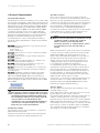
9 Servicing
• Turn off the boiler CH service valves.
• Turn off the cold water inlet service valve.
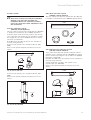
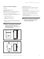
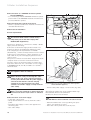
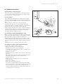
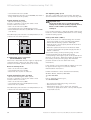
• Release the three clamps (1), remove the combustion
chamber cover (2).
2
1
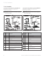
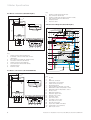
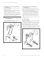
9.2.1 For thermoCOMPACT 615, 637 and turboMAX
plus 837
• Remove the flue gas connector (2a) on the fan.
• Remove the retaining spring (3).
• 15 kW: Pull the three cables (4) and two tubes (5) from
the fan assembly.
• 37 kW: Remove both plugs (not illustrated) and both
hoses (5) from the fan.
• Remove the fan assembly (6).
• Remove the four screws (7) and detach the front cover
panel from the combustion chamber (8).
• Check the burner (9) and heat exchanger fins (10) and
remove any loose deposits with a soft brush.
2a
3
4
4
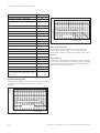
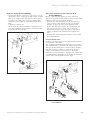
9.2.2 For thermoCOMPACT 620, 624, 628,
turboMAX pro 24, 28 and turboMAX plus 824,
828
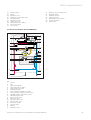
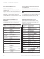
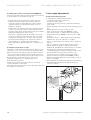
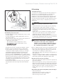
• Pull the three cables (4) and two tubes (5) from the
fan assembly.
• Remove the fan assembly (6a, 6b, 6c).
• Remove the four screws (7) and detach the front cover
panel from the combustion chamber (8).
• Check the burner (9) and heat exchanger fins (10) and
remove any loose deposits with a soft brush.
5
5
4
6
8
10
9
• Reassemble in reverse order.
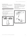
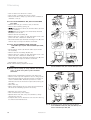
Check central heating expansion vessel.
7
Note!
It is not necessary to carry out this check every
year – a check every three years should be
sufficient.
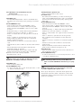
Fig. 9.1a Cleaning the burner and primary heat exchanger
(thermoCOMPACT 615, 637 and turboMAX plus 837)
2
• Release the system water pressure from the boiler.
• Remove valve cap from expansion vessel charge point.
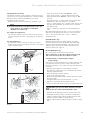
• Check that the internal charge pressure of expansion
vessel is between 0.7 - 0.9 bar. If pressure is lower
than this the vessel should be re-pressurised using an
air pump.
• Refit valve cap.
• Open central heating service valves and re-pressurise
the boiler and heating system if necessary.
1
4
5
5
6c
6a
6b
• Open the gas service valve.
• Turn on the mains power supply.
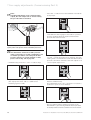
• Operate the boiler and carry out soundness, safety
and function checks.
• Complete the service interval record section in the log
book and leave with the user.
8
10
9
7
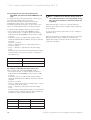
Fig. 9.1b Cleaning the burner and primary heat exchanger
thermoCOMPACT 620, 624, 628, turboMAX pro 24,
28 and turboMAX plus 824, 828
36
Instructions for