Download Campbell CRS456 Instruction manual
Transcript
INSTRUCTION MANUAL
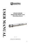
CRS451/CRS456 Submersible
Water-Level Recording Sensor
Revision: 1/14
C o p y r i g h t © 2 0 1 3 - 2 0 1 4
C a m p b e l l S c i e n t i f i c , I n c .
Warranty
“PRODUCTS MANUFACTURED BY CAMPBELL SCIENTIFIC, INC. are
warranted by Campbell Scientific, Inc. (“Campbell”) to be free from defects in
materials and workmanship under normal use and service for twelve (12)
months from date of shipment unless otherwise specified in the corresponding
Campbell pricelist or product manual. Products not manufactured, but that are
re-sold by Campbell, are warranted only to the limits extended by the original
manufacturer. Batteries, fine-wire thermocouples, desiccant, and other
consumables have no warranty. Campbell’s obligation under this warranty is
limited to repairing or replacing (at Campbell’s option) defective products,
which shall be the sole and exclusive remedy under this warranty. The
customer shall assume all costs of removing, reinstalling, and shipping
defective products to Campbell. Campbell will return such products by surface
carrier prepaid within the continental United States of America. To all other
locations, Campbell will return such products best way CIP (Port of Entry)
INCOTERM® 2010, prepaid. This warranty shall not apply to any products
which have been subjected to modification, misuse, neglect, improper service,
accidents of nature, or shipping damage. This warranty is in lieu of all other
warranties, expressed or implied. The warranty for installation services
performed by Campbell such as programming to customer specifications,
electrical connections to products manufactured by Campbell, and product
specific training, is part of Campbell’s product warranty. CAMPBELL
EXPRESSLY DISCLAIMS AND EXCLUDES ANY IMPLIED
WARRANTIES OF MERCHANTABILITY OR FITNESS FOR A
PARTICULAR PURPOSE. Campbell is not liable for any special, indirect,
incidental, and/or consequential damages.”
Assistance
Products may not be returned without prior authorization. The following
contact information is for US and international customers residing in countries
served by Campbell Scientific, Inc. directly. Affiliate companies handle
repairs for customers within their territories. Please visit
www.campbellsci.com to determine which Campbell Scientific company serves
your country.
To obtain a Returned Materials Authorization (RMA), contact CAMPBELL
SCIENTIFIC, INC., phone (435) 227-9000. After an application engineer
determines the nature of the problem, an RMA number will be issued. Please
write this number clearly on the outside of the shipping container. Campbell
Scientific’s shipping address is:
CAMPBELL SCIENTIFIC, INC.
RMA#_____
815 West 1800 North
Logan, Utah 84321-1784
For all returns, the customer must fill out a “Statement of Product Cleanliness
and Decontamination” form and comply with the requirements specified in it.
The form is available from our web site at www.campbellsci.com/repair. A
completed form must be either emailed to [email protected] or faxed to
(435) 227-9106. Campbell Scientific is unable to process any returns until we
receive this form. If the form is not received within three days of product
receipt or is incomplete, the product will be returned to the customer at the
customer’s expense. Campbell Scientific reserves the right to refuse service on
products that were exposed to contaminants that may cause health or safety
concerns for our employees.
Table of Contents
PDF viewers: These page numbers refer to the printed version of this document. Use the
PDF reader bookmarks tab for links to specific sections.
1. Introduction ................................................................. 1
2. Cautionary Statements ............................................... 1
3. Initial Inspection and Handling Guidelines .............. 1
3.1
Ships With ............................................................................................ 2
4. Overview ...................................................................... 2
5. Specifications ............................................................. 2
6. Installation ................................................................... 4
6.1
6.2
6.3
6.4
6.5
6.6
6.7
Appropriate Depth ................................................................................ 4
Avoiding Freezing Conditions ............................................................. 5
Dislodge Bubbles ................................................................................. 5
Well Installation ................................................................................... 5
Other Installations ................................................................................ 6
Battery Voltage Reading ...................................................................... 6
Attaching Suspension Cable to CRS451/CRS456 ............................... 6
7. Programming .............................................................. 8
7.1
7.2
7.3
7.4
Settings ................................................................................................. 8
Connect to the CRS451/CR456............................................................ 8
Configure CRS45X for Measurements ................................................ 9
Compensating Measurements for Barometric Pressure...................... 15
7.4.1 Using an Additional CRS45X ..................................................... 15
7.4.2 Using a Barometer ...................................................................... 15
8. Maintenance .............................................................. 20
8.1
8.2
8.3
Every Visit ......................................................................................... 20
Every Two to Three Years or on a Rotating Schedule ....................... 20
Battery Replacement .......................................................................... 21
9. Troubleshooting........................................................ 26
i
Table of Contents
Appendices
A. Calibration Certificate ............................................. A-1
B. Conversion to Units of Measurement ................... B-1
Table
B-1.
Conversion Factors .......................................................................... B-1
ii
CRS451/CRS456 Submersible
Water-Level Recording Sensor
1.
Introduction
The CRS451 consists of a water-level and water-temperature sensor that has its
own time clock and memory to store the collected data, in a compact stainlesssteel case. This frees users to place the sensor in remote sites and let it collect
data for long periods of time. The CRS451/CRS456 supports standard timebased scanning and recording along with event-based recording based on water
level change (Delta) or logarithmic time sequence for pump and slug tests.
HydroSci software is included and supports test set up, data retrieval, and data
display.
The CRS451 has a 316L stainless-steel case that can be submerged in most
canals, wells, ponds, lakes, and streams. The CRS456 has a rugged titanium
case that allows it to be used in saltwater or other harsh environments.
Before using the CRS451/CRS456, please study:
•
•
•
2.
3.
Section 2, Cautionary Statements
Section 3, Initial Inspection
Section 6, Installation
Cautionary Statements
•
The CRS451/CRS456 will be damaged if encased in frozen liquid (see
Section 6.2, Avoiding Freezing Conditions, for more information).
•
Although the CRS451/CRS456 is a rugged and reliable device, it is also a
highly precise scientific instrument and should be handled as such.
•
Dropping the instrument or allowing it to “free fall” down a well may
damage the transducer.
•
Confirm the compatibility of the instrument to non-water environments
before installation.
•
The CRS456 should be used in harsh water applications, including salt
water.
Initial Inspection and Handling Guidelines
•
Upon receipt of the CRS451/CRS456, inspect the packaging for any signs
of shipping damage. File damage claims with the shipping company.
•
Immediately check package contents against the shipping documentation
(see Section 3.1, Ships With). Contact Campbell Scientific with any
discrepancies.
1
CRS451/CRS456 Submersible Water-Level Recording Sensor
•
3.1
4.
The model number and pressure range are etched on the housing. Check
this information against the shipping documentation to ensure that the
expected product was received.
Ships With
•
27555 USB 2.0 Cable Type A Male to Micro B Male, 6ft
•
29225 HydroSci Software on CD
Overview
The CRS451/CRS456, Submersible Water-Level Recording Sensor, provides
reliable, accurate pressure/level measurements that are fully temperature
compensated.
The 24 bit A/D has simultaneous 50/60 Hz rejection and automatic calibration
for each measurement. A number of additional advanced measurement
techniques are employed to harness the best possible performance available
from today’s state of the art pressure sensor technology. The CRS451/CRS456
reverts to a low power sleep state between measurements. A series of
measurements are performed yielding a temperature and pressure value. This
measurement cycle can be as fast as 1 second.
The design features a piezoresistive sensor housed in a 316L stainless steel
(CRS451) or titanium (CRS456) package to enhance reliability. The rugged
construction makes the CRS451/CRS456 suitable for water level measurement
in irrigation applications, water wells, lakes, streams, and tanks. The titanium
package of the CRS456 makes it ideal for salt water or other harsh
environments.
The CRS451/CRS456 has three nose cone options. The weighted nose cone
makes the transducer easier to submerge to depth. The NPT option allows the
sensor to be mounted to a 1/4 inch fitting. The nose cones can be exchanged at
a later time.
Communicating with the CRS451/CRS456 requires a micro USB cable and
HydroSci software running on a computer with Windows XP or later.
Configurable settings can be changed using Campbell Scientific’s HydroSci
software utility.
5.
Specifications
Features:
2
•
Field replaceable batteries
•
Campbell Scientific quality
•
No additional datalogger, enclosure, and power supply; reduces
system costs and simplifies installation
•
Free customer-friendly software for communication, configuration,
data collection
CRS451/CRS456 Submersible Water-Level Recording Sensor
•
Fast scan rate
•
Large data storage capacity
•
High accuracy
•
Long battery life
•
Data retrieval through sealed USB connector
Measurement Time:
< 1 s typical
Output:
micro USB
Internal Data
Collection Memory:
4 MB
HydroSci Supported
Operating Systems:
Windows XP, Windows Vista, or Windows 7
Logging/Scanning Modes:
Standard, Delta, Logarithmic
Power Requirements:
Internal user-replaceable lithium battery
Battery Life:
5+ years when logging interval is once per
hour
Power Consumption
Quiescent Current:
< 80 μA
Measurement/
Communication Current: 4 mA for 1 s measurement
Measurement Ranges1:
Pressure
Pressure
(psig)
(kPa)
0 to 7.25
0 to 50
0 to 14.5
0 to 100
0 to 29
0 to 200
0 to 72.5
0 to 500
0 to 145
0 to 1000
Meters of
fresh water
0 to 5.1
0 to 10.2
0 to 20.4
0 to 50.9
0 to 102
Accuracy
Pressure Reading2:
Temperature:
0.1% full-scale range TEB3
±0.2°C
Resolution:
0.0035% full-scale range
Overpressure:
2x pressure range
Dry Storage Temperature:
–30° to 80°C
Operating Temperature:
0° to 60°C
Feet of
fresh water
0 to 16.7
0 to 33.4
0 to 67
0 to 167
0 to 334.5
3
CRS451/CRS456 Submersible Water-Level Recording Sensor
CAUTION
Freezing conditions may damage the CRS451/CRS456
(see Section 6.2, Avoiding Freezing Conditions, for more
information).
Body Material
CRS451:
CRS456:
316L Stainless Steel
Titanium
Element Material
CRS451:
CRS456:
316L Stainless Steel
Hastelloy®
Standard Cone Material:
Delrin®
Weighted and NPT Material: Stainless Steel
Dimensions
Length:
Diameter:
22.23 cm (8.75 in)
2.22 cm (0.875 in)
Weight:
230 g (0.51 lb)
The CRS451 is a sealed gage sensor and when not submerged will read
approximately 1 bar at sea level and less as elevation increases. The CRS451
is calibrated at 9 pressures starting at 0.6 bar up to full scale referenced to 1
bar. Points below 1 bar are used in the calibration for the benefit of those who
deploy this sensor at elevations above sea level.
1
The accuracy specification listed pertains to the level of accuracy that the
CRS451/CRS456 is able to measure pressure. If a barometric pressure sensor
is used to remove the component of atmospheric pressure from the pressure
reading provided by the CRS451/CRS456 while submerged in a column of
water vented to the atmosphere, the error of the barometric sensor must be
considered when calculating the resulting accuracy of the water level reading.
2
Total Error Band (TEB) includes the combined errors due to nonlinearity,
hysteresis, nonrepeatability, and thermal effects over the compensated
temperature range, per ISA S51.1.
3
6.
Installation
The CRS451/CRS456 is designed for water level measurements. Typical
applications include agricultural water level/flow, water wells, lakes, streams,
and tanks. If the device is to be installed in a liquid other than water or in
contaminated water, check the compatibility of the wetted material. The
CRS456 should be used in harsh water applications, including salt water.
6.1
Appropriate Depth
The CRS451/CRS456 must be installed below the water at a fixed depth. This
depth should be chosen so that the water pressure will never exceed the
transducer’s pressure range (twice its pressure rating).
4
CRS451/CRS456 Submersible Water-Level Recording Sensor
CAUTION
The output reading will not be correct, and the transducer
can be damaged if pressure is twice its pressure rating.
Pressure can be converted to feet of fresh water using the following simple
equation:
1 psi = 2.31 feet of water
For example, the maximum depth with a pressure range of 0 to 7.25 psig is
16.748 feet of water.
6.2
Avoiding Freezing Conditions
Expansion of water due to freezing will irreparably damage the
CRS451/CRS456. The CRS451/CRS456 can be safely deployed in freezing
conditions if the sensor is placed below the frost line. In a lake or channel of
moving water, often the sensor can be placed deep enough to avoid freezing.
In shallow conditions, where the water body is at risk of freezing solid, placing
the sensor in a stilling well that extends below the frost line will protect the
sensor from freezing water.
6.3
Dislodge Bubbles
While submersing the CSR451/CRS456, air bubbles may become trapped
inside the nose cone, causing small, offset errors until the bubbles dissolve.
Dislodge these bubbles by gently shaking the CRS451/CRS456 while under
water.
6.4
CAUTION
Hitting the instrument against the well casing or other solid
surface could damage the CRS451/CRS456.
CAUTION
If the bubbles are not removed by rotation and shaking
underwater (or bleeding out the air in a closed system), the
CRS451/CRS456 reading will drift lower by the distance of
the gap as the air is slowly dissolved into the water over
time.
Well Installation
Braided stainless steel cable (pn 29221-L) is used to lower the instrument to an
appropriate depth and to suspend the CRS451/CRS456 in a well.
With long drops, it may be necessary to use the weighted nose cone (option
–WN).
For surface installations the instrument’s body can be strapped with tie wraps
or tape. Campbell Scientific offers cable ties (pn 7421) to secure the cable. If
installing in a well, fasten the cable to the well head.
5
CRS451/CRS456 Submersible Water-Level Recording Sensor
6.5
Other Installations
The CRS451/CRS456 can be installed in any position; however, when it leaves
the factory it is tested in the vertical position. There will be an offset error if
not installed vertically; contact Campbell Scientific for more information.
Strapping the transducer body with tie wraps or tape will not hurt it.
6.6
Battery Voltage Reading
The voltage of the lithium ion battery used in the CRS451/CRS456 will
abruptly decrease at the end of the battery’s useful life, which makes predicting
remaining battery life difficult by measuring battery voltage alone. Knowing
the energy consumption of the CRS451/CRS456 while in operation, HydroSci
displays a predicted remaining battery life by combining an estimate of the
energy consumed based on the totalized measurements since new and direct
battery measurements. For this reason, if the battery is removed from the
CRS451/CRS456 anytime during deployment and then replaced, HydroSci will
assume a fresh battery was added to the device and the estimated remaining
battery life will be overstated.
For similar reasons, if the operating system is upgraded or sent to the
CRS451/CRS456, the estimated remaining battery life will also be exaggerated
by HydroSci.
6.7
Attaching Suspension Cable to CRS451/CRS456
Attach the split ring to the CRS451 cap.
6
CRS451/CRS456 Submersible Water-Level Recording Sensor
7
CRS451/CRS456 Submersible Water-Level Recording Sensor
7.
Programming
Communicating with the CRS451/CRS456 requires a micro USB cable and
HydroSci software running on a computer with Windows XP or later.
The CRS451/CRS456 is configured using the HydroSci software provided with
the unit. A DVD containing HydroSci is shipped with the CRS451/CRS456.
CAUTION
7.1
If you are using an XP computer, please have the driver disc
in the CD/DVD drive before plugging in the USB cord. A
driver will need to be installed before the computer can
connect with the sensor.
Settings
Before connecting to the CRS451/CR456, you can change the sensor name or
the appearance of HydroSci screens by clicking on Settings at the upper right
portion of the HydroSci screen.
7.2
8
Connect to the CRS451/CR456
1.
Select CRS45X from the left margin.
2.
Select appropriate COM Port.
3.
Click Connect button.
CRS451/CRS456 Submersible Water-Level Recording Sensor
7.3
Configure CRS45X for Measurements
1.
Click Configuration.
2.
Select Create New Configuration button located at lower left of screen.
3.
Select the type of measurements you want to make.
a)
NOTE
Barometer Pressure Reference should be selected if you want to use
CR45X sensor as a barometer to compensate for changes in
barometric pressure.
See Section 7.4.2, Using a Barometer, if using the measurements
from a nearby barometer to correct for the barometric pressure.
b) Disable: To preserve battery between deployments always configure
the sensor for storage after use.
9
CRS451/CRS456 Submersible Water-Level Recording Sensor
4.
Add offset to relate water level measurements to a known datum or
reference point. (Aquifer test start at level 0.)
a)
This step is optional and not required.
b) This offset takes effect at the Start Time—which is set in a subsequent
screen—so it is necessary that this sensor be in its permanent
measurement position before the Start Time, otherwise the offset
correction will not be correct.
5.
Select a Start and Stop Time.
a)
10
Select a time in the future when measurements should begin.
Selecting a time in the past will force the sensor to begin making
measurements immediately at the indicated frequency. If an offset
calculation was selected in the previous screen, the sensor will not
make correct measurements. If an offset calculation is needed, a Start
Time must be selected far enough in the future that the sensor can be
properly placed in its measurement position before measurements
begin.
CRS451/CRS456 Submersible Water-Level Recording Sensor
b) If desired, select time in future when measurements should cease.
c)
Select the rate at which measurements will be made. This does not
configure the senor for data storage, only the rate at which
measurements are made.
11
CRS451/CRS456 Submersible Water-Level Recording Sensor
6.
Select and Name Data Tables for Datalogging.
a)
Up to four different Data Tables can archive data at independent
intervals with any combination of elements (samples, averages,
maximum, etc).
b) Contents of the Data Table are selected in the next screen.
12
CRS451/CRS456 Submersible Water-Level Recording Sensor
7.
Select which data, in which format and unit of measurement, is to be
included in each of the data tables selected in the previous screen.
13
CRS451/CRS456 Submersible Water-Level Recording Sensor
8.
Once the Data Tables have been configured, the configuration process is
finished and the Finish button can be selected.
9.
Once the configuration is complete, it must be copied to the CRS451
before it will take effect. Click on Apply Configuration to CRS45X to
start this process.
Before sending the configuration file to the CRS45X, HydroSci may provide a
warning that your start and stop times may need adjusting. If the Start Time is
in the past, the CRS45X will immediately begin logging data but any offset
you may have applied will not be effective. Also, if the Stop Time is in the
past, no data will be logged.
Save data if you have not already done so. Archived data is purged from the
CRS45X when a new configuration file is copied so you will want to collect
any data before sending the configuration file.
This option allows you to save the configuration file for future reference or for
easy use in other similarly deployed sensors.
The CRS451 is calibrated to pressure units in psi. TABLE B-1 contains the
conversion factors used to convert psi to depth of water.
14
CRS451/CRS456 Submersible Water-Level Recording Sensor
7.4
Compensating Measurements for Barometric Pressure
The CRS45X pressure transducer is unvented; therefore it is monitoring sealed
gage pressure and should be corrected for barometric pressure.
7.4.1 Using an Additional CRS45X
One simple way to complete this correction is to deploy an additional CRS45X
as a reference sensor. For this method, in the Select Field Application window,
choose Barometer Pressure Reference (see Section 7.3, Configure CRS45X for
Measurements).
7.4.2 Using a Barometer
The barometric pressure data from a nearby Campbell Scientific weather
station or other Campbell Scientific monitoring platform can also be used to
compensate for barometric pressure. The Data tab is used to process and
merge the data file from the test sensor with the data file from the barometric
reference sensor. The procedure for doing this follows:
1.
Press the browse button next to the Collected Data File field to browse to
the data files retrieved from the CRS45X.
15
CRS451/CRS456 Submersible Water-Level Recording Sensor
2.
Select a data file you wish to be corrected by barometric pressure values.
a)
3.
16
The Field Application Used to Produce Collected Measurement
Data information will be shown based on the collected data file
selected.
Press the browse button next to the Barometric Pressure Reference Data
File field to browse the data files from the barometric reference sensor.
CRS451/CRS456 Submersible Water-Level Recording Sensor
4.
Select a data file you wish to use as the barometric pressure reference data
file.
a)
Use the drop-down list to select the Barometric Pressure Reference
Column in the data file.
The reference column must be a measurement of pressure or level. If
from a nearby Campbell Scientific weather station, note that the
reference column must have units associated with it. The units can be
any pressure or level units as defined in HydroSci and they must
match exactly the HydroSci abbreviation as shown here.
The following pressure and level units are defined in HydroSci:
HydroSci Abbreviation
Units of Measure
mm
millimeter
m
meter
ft
feet
in
inch
mb
millibar
bar
bar
kPa
kilopascal
psia
psi absolute
17
CRS451/CRS456 Submersible Water-Level Recording Sensor
5.
Press the browse button next to the Corrected Data File field to indicate
where the corrected data file should be stored.
Rename the file as applicable.
6.
After completing all of the fields, press the Build Corrected Data File
button.
7.
Once the corrected data file has been built, press the View Corrected
Data File button to open the file in View.
The View Data button at the bottom of the screen can also be used to open
View.
18
CRS451/CRS456 Submersible Water-Level Recording Sensor
In View, use the File | Open menu item to browse to any data file you
would like to view.
To select the data values to be graphed, click on the column heading(s) in
the data file with a single mouse click. The selection will be highlighted
and will automatically be added to the graph.
Multiple columns can be added by holding the Ctrl key and dragging the
mouse pointer over the column headings.
To see the graph, press the Graph button. The graph will then appear on a
new screen.
An example of the measured data and the barometric pressure
compensated data is shown here.
The original data are shown in blue and the compensated data are shown in
red.
19
CRS451/CRS456 Submersible Water-Level Recording Sensor
The barometric pressure sensor data are shown below, also in blue.
8.
Maintenance
Campbell Scientific recommends that the CRS451/CRS456 be factory
recalibrated every 24 months. Before a CRS451/CRS456 is sent to Campbell
Scientific, the customer must get an RMA (returned material authorization)
number and fill out the Declaration of Hazardous Material and
Decontamination form.
8.1
8.2
Every Visit
•
Collect data.
•
Visually inspect the physical conditions.
•
Check battery condition by using a laptop and HydroSci software to view
the battery voltage (see Section 6.6, Battery Voltage Reading). The
battery replacement procedure is provided in Section 8.3, Battery
Replacement.
•
Check all readings; adjust offsets if necessary.
•
Check recent data.
Every Two to Three Years or on a Rotating Schedule
•
20
Send the CRS451/CRS456 in for inspection and calibration.
CRS451/CRS456 Submersible Water-Level Recording Sensor
8.3
Battery Replacement
Remove the set screws on the cap end of the CRS451.
New Battery
Screwdriver
21
CRS451/CRS456 Submersible Water-Level Recording Sensor
Gently pull the end out of the housing.
Unplug the connecter.
22
CRS451/CRS456 Submersible Water-Level Recording Sensor
Gently pull the battery out the end.
Disconnect the battery.
Remove the battery.
Slide in the new battery.
Plug in the new battery.
23
CRS451/CRS456 Submersible Water-Level Recording Sensor
Slide the battery into the housing.
Reconnect the cable.
24
CRS451/CRS456 Submersible Water-Level Recording Sensor
Gently slide the end piece with its O-rings into the housing.
NOTE
Nicking the O-ring could result in a leak.
Line up the holes and insert the set screw. Do not over tighten the set screw.
25
CRS451/CRS456 Submersible Water-Level Recording Sensor
9.
Troubleshooting
The most common causes for erroneous pressure transducer data include:
•
•
•
Low battery
Damaged CRS451/CRS456
Water damage
Damage to diaphragm due to excessive pressure
Atmospheric pressure not subtracted from pressure reading
Problem:
Unit will not respond when attempting USB communications.
Suggestion:
Replace battery.
Correct COM Port used for communication not selected in HydroSci.
26
Appendix A. Calibration Certificate
Each CRS451/CRS456 has been calibrated to meet printed accuracy
specification at multiple temperature and pressure ranges. If additional
verification is required, a Calibration Certificate can be purchased for each
CRS451/CRS456 Water-Level Recording Sensor.
The Instrument Data Report provides a list of the pressure and temperature at
which the sensor was tested.
Pressure [kPa] is the pressure applied (listed in kilopascals) to the sensor.
Temperature [°C] is the temperature inside the test chamber at the time of
testing. Pressure After [kPa] represents the resulting measurement output by
the CRS451/CRS456 at the given pressure and temperature. Finally,
Deviation After [%F.S.] provides the difference between the actual pressure
applied to the sensor and the pressure measurement output by the sensor. This
value is listed as a percentage of the full scale range of the sensor.
When a CRS451/CRS456 is returned to Campbell Scientific for calibration, the
sensor will be returned with an Instrument Data Report. This report will
include values in the Pressure Before [kPa] column. These values represent
the measured pressure the sensor returns at the specified pressure and
temperature, BEFORE calibration.
A-1
Appendix A. Calibration Certificate
A-2
Appendix B. Conversion to Units of
Measurement
TABLE B-1. Conversion Factors
Unit of Measurement
Factor of Conversion
Feet
2.3066587369
Inches
27.679904843
Meters
0.1019716213
Millimeters
101.9716213
B-1
Appendix B. Conversion to Units of Measurement
B-2
Campbell Scientific Companies
Campbell Scientific, Inc. (CSI)
815 West 1800 North
Logan, Utah 84321
UNITED STATES
www.campbellsci.com • [email protected]
Campbell Scientific Africa Pty. Ltd. (CSAf)
PO Box 2450
Somerset West 7129
SOUTH AFRICA
www.csafrica.co.za • [email protected]
Campbell Scientific Australia Pty. Ltd. (CSA)
PO Box 8108
Garbutt Post Shop QLD 4814
AUSTRALIA
www.campbellsci.com.au • [email protected]
Campbell Scientific do Brasil Ltda. (CSB)
Rua Apinagés, nbr. 2018 ─ Perdizes
CEP: 01258-00 ─ São Paulo ─ SP
BRASIL
www.campbellsci.com.br • [email protected]
Campbell Scientific Canada Corp. (CSC)
14532 – 131 Avenue NW
Edmonton AB T5L 4X4
CANADA
www.campbellsci.ca • [email protected]
Campbell Scientific Centro Caribe S.A. (CSCC)
300 N Cementerio, Edificio Breller
Santo Domingo, Heredia 40305
COSTA RICA
www.campbellsci.cc • [email protected]
Campbell Scientific Ltd. (CSL)
Campbell Park
80 Hathern Road
Shepshed, Loughborough LE12 9GX
UNITED KINGDOM
www.campbellsci.co.uk • [email protected]
Campbell Scientific Ltd. (CSL France)
3 Avenue de la Division Leclerc
92160 ANTONY
FRANCE
www.campbellsci.fr • [email protected]
Campbell Scientific Ltd. (CSL Germany)
Fahrenheitstraße 13
28359 Bremen
GERMANY
www.campbellsci.de • [email protected]
Campbell Scientific Spain, S. L. (CSL Spain)
Avda. Pompeu Fabra 7-9, local 1
08024 Barcelona
SPAIN
www.campbellsci.es • [email protected]
Please visit www.campbellsci.com to obtain contact information for your local US or international representative.


