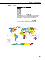
1
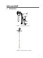
INSTRUCTION MANUAL
HS2 and HS2P
(HydroSense II)
Revision: 3/14
C o p y r i g h t © 2 0 1 1 - 2 0 1 4
C a m p b e l l S c i e n t i f i c , I n c .
Warranty
“PRODUCTS MANUFACTURED BY CAMPBELL SCIENTIFIC, INC. are
warranted by Campbell Scientific, Inc. (“Campbell”) to be free from defects in
materials and workmanship under normal use and service for twelve (12)
months from date of shipment unless otherwise specified in the corresponding
Campbell pricelist or product manual. Products not manufactured, but that are
re-sold by Campbell, are warranted only to the limits extended by the original
manufacturer. Batteries, fine-wire thermocouples, desiccant, and other
consumables have no warranty. Campbell’s obligation under this warranty is
limited to repairing or replacing (at Campbell’s option) defective products,
which shall be the sole and exclusive remedy under this warranty. The
customer shall assume all costs of removing, reinstalling, and shipping
defective products to Campbell. Campbell will return such products by surface
carrier prepaid within the continental United States of America. To all other
locations, Campbell will return such products best way CIP (Port of Entry)
INCOTERM® 2010, prepaid. This warranty shall not apply to any products
which have been subjected to modification, misuse, neglect, improper service,
accidents of nature, or shipping damage. This warranty is in lieu of all other
warranties, expressed or implied. The warranty for installation services
performed by Campbell such as programming to customer specifications,
electrical connections to products manufactured by Campbell, and product
specific training, is part of Campbell’s product warranty. CAMPBELL
EXPRESSLY DISCLAIMS AND EXCLUDES ANY IMPLIED
WARRANTIES OF MERCHANTABILITY OR FITNESS FOR A
PARTICULAR PURPOSE. Campbell is not liable for any special, indirect,
incidental, and/or consequential damages.”
Assistance
Products may not be returned without prior authorization. The following
contact information is for US and international customers residing in countries
served by Campbell Scientific, Inc. directly. Affiliate companies handle
repairs for customers within their territories. Please visit
www.campbellsci.com to determine which Campbell Scientific company serves
your country.
To obtain a Returned Materials Authorization (RMA), contact CAMPBELL
SCIENTIFIC, INC., phone (435) 227-9000. After an application engineer
determines the nature of the problem, an RMA number will be issued. Please
write this number clearly on the outside of the shipping container. Campbell
Scientific’s shipping address is:
CAMPBELL SCIENTIFIC, INC.
RMA#_____
815 West 1800 North
Logan, Utah 84321-1784
For all returns, the customer must fill out a “Statement of Product Cleanliness
and Decontamination” form and comply with the requirements specified in it.
The form is available from our web site at www.campbellsci.com/repair. A
completed form must be either emailed to [email protected] or faxed to
(435) 227-9106. Campbell Scientific is unable to process any returns until we
receive this form. If the form is not received within three days of product
receipt or is incomplete, the product will be returned to the customer at the
customer’s expense. Campbell Scientific reserves the right to refuse service on
products that were exposed to contaminants that may cause health or safety
concerns for our employees.
Table of Contents
PDF viewers: These page numbers refer to the printed version of this document. Use the
PDF reader bookmarks tab for links to specific sections.
1. Introduction ................................................................. 1
2. Cautionary Statements ............................................... 2
3. Quickstart .................................................................... 2
4. Overview ...................................................................... 3
5. Specifications ............................................................. 6
5.1
Display Specifications .......................................................................... 6
5.1.1 Current Drain ................................................................................ 7
5.2
Sensors Specifications .......................................................................... 7
5.2.1 Volumetric Water Content Measurement ..................................... 7
5.2.2 Physical ......................................................................................... 7
5.3
HS2P Pole Assembly ........................................................................... 7
5.3.1 Height............................................................................................ 8
5.3.2 Weight ........................................................................................... 8
6. Operation ..................................................................... 8
6.1
6.2
6.3
6.4
Assembly and First Use ....................................................................... 8
Measurements ...................................................................................... 8
Water Content Data .............................................................................. 8
Water Deficit Data ............................................................................... 9
6.4.1 Soil Types ..................................................................................... 9
6.4.2 Configuring Soil Profiles ............................................................ 10
6.4.3 Storage ........................................................................................ 12
6.4.4 Proper Measurement Technique and Limitations ....................... 12
6.4.4.1 Measurement Principle ..................................................... 12
6.4.4.2 Rod Insertion .................................................................... 12
6.4.4.3 Soil Factors Affecting Measurement ................................ 13
6.4.4.4 Measurements in Special Materials .................................. 13
7. User Interface ............................................................ 13
7.1
7.2
7.3
Buttons ............................................................................................... 14
Splash Screen ..................................................................................... 14
Main Screen ....................................................................................... 14
7.3.1 GPS Information ......................................................................... 15
7.3.2 Status Information ....................................................................... 15
7.3.3 Measurement Display ................................................................. 16
7.3.4 Deficit Display ............................................................................ 17
8. Data Storage and Retrieval ...................................... 17
8.1
Storing Data ....................................................................................... 17
i
Table of Contents
8.2
8.3
8.4
8.5
What is stored? .................................................................................. 18
Software ............................................................................................ 18
Connecting via Bluetooth .................................................................. 18
Collecting Data .................................................................................. 19
9. GPS ............................................................................19
9.1
9.2
GPS Synchronization......................................................................... 19
Geotagging and Zones ....................................................................... 19
10. Troubleshooting ........................................................21
11. Maintenance ..............................................................22
11.1 Batteries ............................................................................................. 22
11.1.1 Replacing the Battery Pack ........................................................ 22
11.2 Removing Display from HS2P Pole .................................................. 23
11.3 Rod Replacement .............................................................................. 24
11.4 Replacing an HS2P Sensor ................................................................ 26
11.5 Operating System Updates ................................................................ 26
Appendix
A. Configuration Menus .............................................. A-1
A.1
A.2
A.3
A.4
A.5
A.6
A.7
A.8
A.9
A.10
A.11
A.12
A.13
A.14
A.15
A.16
A.17
A.18
A.19
A.20
Main Menu ...................................................................................... A-1
Deficit Mode.................................................................................... A-1
Bluetooth Power .............................................................................. A-1
Time/Date Menu.............................................................................. A-2
Time Set .......................................................................................... A-2
Date Format ..................................................................................... A-2
Time Zone ....................................................................................... A-3
Time Synchronization ..................................................................... A-4
Display Settings ............................................................................... A-4
Contrast ........................................................................................... A-4
Brightness ........................................................................................ A-5
Backlight on Time ........................................................................... A-5
Light Sensing................................................................................... A-5
GPS Settings .................................................................................... A-6
GPS Power ...................................................................................... A-6
Coordinate Format ........................................................................... A-6
System Settings ............................................................................... A-7
System on Time ............................................................................... A-7
Restore Settings ............................................................................... A-7
Serial Number.................................................................................. A-8
1-1.
1-2.
4-1.
4-2.
4-3.
HS2 HydroSense II System ................................................................. 1
HS2P HydroSense II Pole System ....................................................... 1
HS2 Parts in Hard Carrying Case ........................................................ 5
HS2P Carrying Tote ............................................................................ 6
HS2P Parts........................................................................................... 6
Figures
ii
Table of Contents
Tables
4-1.
4-2.
6-1.
7-1.
Comparison of HydroSense II and HydroSense(I) ............................... 3
HydroSense II Parts.............................................................................. 5
Default Soil Profiles ........................................................................... 10
Status Icons ........................................................................................ 16
iii
Table of Contents
iv
HS2 and HS2P
1.
Introduction
FIGURE 1-1. HS2 HydroSense II System
FIGURE 1-2. HS2P HydroSense II Pole System
1
HS2 and HS2P
The HydroSense II is an easy-to-use, portable device for measuring volumetric
water content of soil. The major components of the system are the display, the
sensor, and the software. A sensor with 12 cm rods (model CS659 or CS659P)
and a sensor with 20 cm rods (model CS658 or CS658P) are available.
Campbell Scientific offers the HS2, the standard HydroSense II system, and
the HS2P, a HydroSense II system with a strong handle and pole. FIGURE
1-1, HS2 HydroSense II System (p. 1) shows the HS2 and FIGURE 1-2, HS2P
HydroSense II Pole System (p. 1) shows the HS2P.
NOTE
2.
3.
Cautionary Statements
•
The connectors that connect the HydroSense II display to the sensor are a
push-pull type with locators to align the connectors. DO NOT TWIST.
The connectors can be damaged if the user twists them or attempts to
screw or unscrew them.
•
Remove the AA batteries before putting the HydroSense II display into
storage.
•
An unobstructed view of the sky may be required to achieve the most
accurate global position data possible from the HydroSense II GPS.
•
Sensor rods must be completely inserted into the soil before making a
measurement.
1.
Remove the HS2 display or HS2P from the carry case.
2.
Remove the blue protective strip from the display window.
Quickstart
NOTE
CAUTION
2
Throughout the manual, HydroSense II refers to both the HS2 and
HS2P, unless specified otherwise.
Steps 3 and 4 are for the HS2 only because the HS2P comes fully
assembled. If using an HS2P, go directly to step 5.
3.
Remove the HS2 sensor from the carry case.
4.
Connect the HS2 sensor to the display by mating the connector on the
cable to the connector at the bottom of the display. DO NOT TWIST the
connectors.
The connector is a push-pull type with locators to align the
connectors. The connectors can be damaged if the user
attempts to screw or unscrew them.
To mate the
connectors, simply bring them together and turn until they
are aligned, then applying firm pressure, slide them together
until they click. To disconnect, pull back on the connector
collar with the thumb and forefinger and pull the two
connectors apart.
HS2 and HS2P
NOTE
5.
Turn on the HydroSense II by holding the
6.
Establishing a GPS sync may take up to one minute or more. When the
GPS icon is displayed ( ), synchronization has been successful.
Measurements with GPS data can now be taken. See Appendix A.14, GPS
Settings (p. A-6) for information on toggling the GPS.
The HydroSense II stores positional information (when available),
time, and date with measurements. To reliably take advantage of
the GPS, use the HydroSense II outdoors with a clear view of the
sky. Measurements can be made and data stored without a GPS
(p. 19) signal; however, the HydroSense II Support Software
(HydroSoft) will be unable to later group and display data
geographically.
7.
NOTE
button for 3 seconds.
Insert the sensor rods fully into the soil. The HS2P uses a plastic
“bumper” that covers the rod mounting nuts. Insert the rods into the soil
up to the plastic “bumper”.
Only remove the plastic bumper when replacing soil rods and put
it back on when done.
8.
To take a measurement, press
. When the hourglass icon ( ) in the
lower right of the screen is extinguished, the measured VWC and period
are shown on the screen.
9.
Press
to store the measurement. Assuming the GPS is in sync, follow
the prompts to create a zone.
10. Data are now stored in memory. To retrieve data, first establish a
Bluetooth link with your PC, and then collect data using the HydroSense II
support software. See Section 8.4, Connecting via Bluetooth (p. 18) and
Section 8.5, Collecting Data (p. 19).
4.
Overview
The HydroSense II is a portable system for measuring volumetric water content
of soil. It is an improved successor to the HydroSense. TABLE 4-1,
Comparison of HydroSense II and HydroSense(I) compares features of the
HydroSense II and HydroSense (I).
TABLE 4-1. Comparison of HydroSense II and HydroSense(I)
Feature
HydroSense II
HydroSense (I)
Volumetric water
content and period
Yes, period as μs
Yes, period as ms
Relative water content
& water deficit with
wet and dry references
Yes (10 profiles)
Yes (5 sites)
3
HS2 and HS2P
Sensor rod length
20 cm and 12 cm
(NOT interchangeable)
20 cm and 12 cm
(interchangeable)
Accuracy
20 cm rods: ±3%
(EC ≤ 4 dS/m)
±3% VWC
(EC < 2 dS/m)
12 cm rods: ±3% (EC≤
6.5 dS/m)
NOTE
GPS and geotagging
Yes
No
GPS zones
Yes
No
Data storage
Yes (1000+ readings)
No
Bluetooth
Yes
No
Date and time
Yes (with GPS accuracy
when available)
No
Display
128 x 64 pixel graphic
LCD
2 line x 16 char
alphanumeric LCD
LCD backlight
Yes
No
Firmware updates
User updateable
Factory only
Field carry case
Yes
No
Portable
Yes
Yes
Battery life
1000+ readings
2000+ readings
Unlike the HydroSense (I), the 12 cm and 20 cm rods of the
HydroSense II are not interchangeable.
The HydroSense II can display relative water content (RWC) based on wet and
dry references set by the user. The unit also displays water deficit, which
indicates how much water is required (in mm of applied water) to return the
soil to the previously saved wet reference.
Measurements are made by fully inserting the sensor rods into the soil and
pressing
. The process takes 2 to 3 seconds. The measurement can be
stored and later downloaded to a computer for display and analysis.
Communications between the computer and HydroSense II are via Bluetooth
(p. 18). The HydroSense II includes a GPS (Global Positioning System)
(p. 19) receiver that enables data to be stored with position information
(geotagged (p. 19)).
The HydroSense II has these default power saving features:
4
•
turns off when idle for a configurable period
•
adjustable backlight brightness and on-time
•
backlight automatically disabled in bright conditions
•
GPS and Bluetooth can each be forced off.
HS2 and HS2P
The HydroSense II system consists of the items listed in TABLE 4-2,
HydroSense II Parts. These parts are shown in FIGURE 4-1, HS2 Parts in
Hard Carrying Case, FIGURE 4-2, HS2P Carrying Tote, and FIGURE 4-3,
HS2P Parts.
TABLE 4-2. HydroSense II Parts
Qty
HS2 Part
1
HydroSense II measurement and display unit
1
1
HS2P Part
HS2P Insertion Pole Assembly
(pn 29153)
CS658 (20 cm) or CS659
(12 cm) water content sensor
CS658P (20 cm) or CS659P
(12 cm) water content sensor
4
AA batteries (factory installed inside the display)
1
Spare battery holder (pn 28404); spare batteries not included
1
Wrench (pn 26156) for installing / replacing rods
1
Loctite thread locking compound (pn 13665) for rod replacement
1
Phillips screwdriver (pn 6290)
1
1
Hard carrying case (pn 27789)
Carrying tote (pn 29468) or hard
carrying case (pn 27789)
HydroSense II Support Software (HydroSoft) on CD
Screwdriver
CS658
Wrench
Loctite
HS2 Display
Spare
Battery
Holder
FIGURE 4-1. HS2 Parts in Hard Carrying Case
5
HS2 and HS2P
FIGURE 4-2. HS2P Carrying Tote
HydroSoft CD
HS2P Pole
CS659P
Display
Wrench
Spare Battery Holder
Loctite
FIGURE 4-3. HS2P Parts
Below are spare and supporting parts available from Campbell Scientific:
•
•
•
5.
Specifications
5.1
6
Spare 20 cm rods (pn 26483) for the CS658 or CS658P sensor
Spare 12 cm rods (pn 10184) for the CS659 or CS659P sensor
USB Bluetooth adapter for supporting PCs (pn 28411).
Display Specifications
GPS Accuracy:
±5 m (16.4 ft) typical;
±1 ms time with GPS sync
Data storage:
>1000 records (ring memory)
Zone storage:
>100 records (fill and stop)
Display:
128 x 64 pixel graphic LCD
Backlight:
blue / white LED; brightness adjustable
Compatibility:
Bluetooth (to ≈10 m);
Google Earth (via software)
Weight:
0.34 kg (0.75 lb)
HS2 and HS2P
Dimensions:
200 x 100 x 58 mm (7.9 x 3.9 x 2.3 in)
Source:
4 x AA alkaline batteries
Battery life:
6 to 12 months (depends on usage and battery
quality)
5.1.1 Current Drain
5.2
Asleep:
20 μA
Backlight off:
2 mA
Backlight 60%:
18 mA
Backlight 100%:
30 mA
GPS active:
35 mA
Bluetooth active:
30 mA
Sensors Specifications
5.2.1 Volumetric Water Content Measurement
Measurement principle:
time domain reflectometry
Measurement range:
0% – 50%
Precision:
<0.05%
Accuracy:
±3% VWC in mineral soils
with solution EC ≤4.0 dS/m (20 cm rods)
with solution EC ≤6.5 dS/m (12 cm rods)
Weight:
0.45 kg (0.99 lb)
Sensor body dimensions
(L x W x H):
100 x 92 x 40 mm (3.9 x 3.6 x 1.6 in)
Rod length:
20 cm and 12 cm, rods not interchangeable
Rod diameter:
4.7 mm (nominal)
5.2.2 Physical
5.3
HS2P Pole Assembly
Handle width:
29.2 cm (11.5 in)
Pole width:
2.5 cm (1 in)
Pole depth:
2.5 cm (1 in)
7
HS2 and HS2P
5.3.1 Height
Handle to bottom of sensor:
82.3 cm (32.4 in)
Top of display to
bottom of sensor:
96.5 cm (38 in)
With display and sensor:
1.4 kg (3 lb)
Without display:
1.1 kg (2.4 lb)
5.3.2 Weight
6.
Operation
6.1
Assembly and First Use
This information is provided in Section 3, Quickstart.
6.2
Measurements
The HydroSense II presents two distinct data sets. One data set includes
volumetric water content expressed as percent (%) and period (μs). The second
data set includes an estimate of relative water content relative to pre-measured
wet and dry references, and water deficit. Water deficit provides an estimate of
applied water required (in mm) to return the soil to the “wet” water content.
By default, only water content data are displayed. Using the configuration
menu (p. A-1), water deficit data can be enabled to display side-by-side with
water content data.
6.3
Water Content Data
Volumetric water content (VWC) and period (PER) data are retrieved from the
sensor. The HydroSense II sensor uses a proprietary technique to determine
water content over widely varying soils while correcting for a range of bulk
electrical conductivities. Volumetric water content (labeled “VWC” on the
display) and period (labeled “PER” on the display) data are requested from the
sensor via SDI-12 serial protocol.
Soil consists of three main constituents – mineral particles (sand, loam, or
clay), water and air. Air and water occupy the spaces or pores formed between
the mineral particles. In agricultural soils, these pore spaces typically make up
approximately 50% of the soil by volume, with water and air together making
up the remaining 50%. As a result, water content normally ranges from 0% to
50%. In some conditions, the sensor is unable to determine the soil water
content. In these cases an out-of-range symbol (---) is displayed.
NOTE
8
Even when the sensor cannot determine the VWC, the signal
period measurement will always be displayed. In special media
this value can often be used with a soil specific calibration to
estimate water content.
HS2 and HS2P
6.4
Water Deficit Data
Water deficit data help irrigators with water management decisions. By default
the HydroSense II does not show water deficit data on the display screen. To
enable the water deficit data display, turn on Deficit Mode in the configuration
menus (p. A-1).
In water deficit mode, wet and dry references can be stored for up to ten soils.
The current measurement is compared to those reference values and relative
water content (RWC) is calculated on a scale from 0% (dry) to 100% (wet).
While any two volumetric water content measurements can be stored as “wet”
and “dry” references, the normal procedure is to store the wilting point as the
“dry” value and field capacity as “wet”. The relative water content is
calculated as
RWC =
VWC − VWCdry
VWCwet − VWCdry
×100
where
VWC = the current measurement
VWCdry = the dry reference
VWCwet = the wet reference.
For example, a particular clay-loam soil may reach wilting point at 18% and
field capacity at 35%. With these references, a VWC measurement of 24.5%
will display as a relative water content of 38.2%. A VWC of 30% is calculated
as an RWC of 70.6%.
An RWC value greater than 100% indicates that the soil has a water content
value greater than the “wet” reference; a negative value indicates that the water
content is below the “dry” reference.
Water required (in mm of applied water) to return the soil to the “wet”
reference is also calculated and reported as water deficit. A negative deficit
indicates that that the water content is greater than the “wet” reference for that
soil type.
Since the sensors average water content along the length of the rods, the
sample volume difference between the 20 cm and 12 cm sensors is significant.
This difference affects the water deficit value. Therefore, the current
measurement and reference values must be made with the same rod length.
6.4.1 Soil Types
The HydroSense II needs three parameters to calculate relative water content
and deficit:
•
•
•
“wet” water content set point
“dry” water content set point
sensor length
9
HS2 and HS2P
These parameters are soil specific and grouped as “soil profiles”. The
HydroSense II holds up to 10 soil profiles labeled “SOIL 1” through “SOIL
10”.
Some soil profiles are preset to default values. These values may be used or
overwritten as desired, but take care to record what soil type is used for each
profile. The default soil profiles are described in TABLE 6-1, Default Soil
Profiles.
TABLE 6-1. Default Soil Profiles
Soil No
“Dry”
“Wet”
Rod Length
Soil Description
1
7%
15%
20 cm
Sand
2
10%
20%
20 cm
Sandy Loam
3
18%
35%
12 cm
Sandy Clay
4
15%
30%
12 cm
Loam
5
20%
40%
12 cm
Silty Clay
6
17%
35%
12 cm
Clay Loam
6.4.2 Configuring Soil Profiles
When Deficit Mode is enabled (Section 7.3.4, Deficit Display (p. 17)), soil
profiles are accessed from the main screen (p. 14) of the HydroSense II. To
select the current soil profile (“SOIL 1” in the preceding figure), press the
button. The soil profile number will be highlighted. To open the soil profile
list, press
.
The soil profile list should be displayed. Use
to the desired soil profile and press
10
.
to move through the list
HS2 and HS2P
A soil profile page will be displayed. This page shows the reference values
stored for this soil profile and the rod length used.
To select this soil profile to apply to the current measurement, press
highlight SELECT THIS SOIL and press
to
.
New reference values can be set from the soil profile screen. To do so,
correctly insert the sensor in the reference soil and select “WET VWC” or
“DRY VWC” and press
.
The screen will show MEASURING… while the measurement is taken. After
3 to 4 seconds, the soil profile page will be shown with the reference value
changed. Repeat this process for the remaining wet or dry set point.
If desired, the soil profile can be cleared by selecting CLEAR SOIL then
NOTE
.
The CLEAR SOIL operation cannot be undone.
The sensor length stored in a soil profile is automatically updated to match the
sensor used whenever the wet and dry reference values are changed. If the
sensor length used to change one of the references is different to that
previously used for the soil profile, the following screen will be shown.
11
HS2 and HS2P
Selecting NEW PROBE will overwrite the soil profile, clearing the other
reference value, whereas selecting OLD PROBE will discard the measurement
and leave the soil profile unchanged. This feature forces both reference values
to use the same rod length. This step cannot be reversed. Using
,
select the desired option and press
to accept or
measurement and return to the soil profile screen.
to discard the new
Once the soil profile changes are complete, use
to choose SELECT
THIS SOIL and press
the new soil profile.
. This will return to the main screen (p. 14) and use
6.4.3 Storage
The HydroSense II does not store relative water content or deficit
measurements to flash. Only water content measurements are stored.
6.4.4 Proper Measurement Technique and Limitations
6.4.4.1 Measurement Principle
The HydroSense II uses soil dielectric permittivity to estimate volumetric water
content. Dielectric permittivity of water is much greater than that of other soil
constituents making possible the correlation of water content to measured
dielectric permittivity. Additionally, water and air are the only soil
constituents that change appreciably over biological time scales.
The electronics contained in the water content sensor generate the high
frequency electromagnetic energy necessary to polarize water molecules such
that their permittivity can be determined. The energy passes along a
waveguide formed by the two rods and reflects from the end of the rods and
back into the sensor head where the reflected signal is detected and time of
travel is measured. The time of travel along the waveguide is predominantly
dependent on the dielectric permittivity. Since the measured time is the net
result of passing down the length of the rods and back again, it reflects an
average of the water content over the volume of the waveguide. The sensor
electronics also detect electrical conductivity (EC) between the rods and use
this to correct the permittivity measurement. This allows the sensor to operate
in a wider range of soil EC. The calibration coefficients to convert measured
time of travel to dielectric constant and water content are contained within the
sensor head and are the intellectual property of Campbell Scientific.
6.4.4.2 Rod Insertion
For accurate, repeatable measurements, the rods of the sensor must be fully
inserted into the soil. Since the water content is averaged over the length of the
rods, the reading from a 20 cm sensor inserted vertically will be the average of
the soil moisture over the top 20 cm; however, the same rods inserted at 45°
will yield an average of the top 14 cm. This is often used for shallow rooted
crops, such as turf, to measure the average water content in the root zone of the
plant. Inserting the rods completely at an angle often requires more attention
during the insertion action.
The measurement volume of a sensor varies somewhat with soil type. As a
guide, volume extends along the full length of the rods and outward radially
from each rod a distance of approximately 3 cm.
12
HS2 and HS2P
Soil is not homogeneous. Cracks, rocks, pore size, plant roots, and texture
layers are not usually distributed uniformly throughout a measured profile. If
the water content over a large area such as a cropped field is to be determined,
several measurements may be required to establish a representative
measurement.
6.4.4.3 Soil Factors Affecting Measurement
The HydroSense II is predominantly sensitive to dielectric permittivity, and
therefore soil water content (see Section 6.4.4.1, Measurement Principle
(p. 12)). Other physical properties of the soil can affect the measurement. If
the soil contains a large clay fraction or has high electrical conductivity (EC),
the applied signal can be attenuated sufficiently to affect detection of the
reflected signal in the sensor electronics. A very high organic matter fraction
has a similar effect. The HydroSense II will still respond to changes in water
content in these atypical soils, but its response will deviate from that of soils
wherein the attenuation factors are present in small non-interfering amounts.
The calibration coefficients fixed in the HydroSense II sensor were determined
in laboratory studies on typical soils. When measuring atypical soils, user
determined coefficients can often be applied to the measured period value.
Rocky soils can make rod insertion difficult and introduce variability in water
content measurements taken in the same general area. Rocks occupy space
otherwise occupied by the fine soil fraction, but they do not hold water in the
same manner as soil. If two proximal measurements are made in rocky soil,
the measured water content can differ significantly if large quantities of rock
occupy part of the sensitive volume of one measurement but not the other.
6.4.4.4 Measurements in Special Materials
The HydroSense II was designed for use in agricultural soils, but the
measurement technique underlying the instrument supports other potential
applications. Other porous media can be monitored using the period value
shown on the display. The period is strongly related to dielectric permittivity
of the material surrounding the sensor rods and can be used as a relative value
to measure changes in the material of interest. Period generally increases
proportionally with water content. For actual water content values, a soil
specific calibration can be performed using an independent measure of water
content such as gravimetric analysis. A calibration equation can then be
derived to relate period to water content.
7.
User Interface
The following section contains a detailed description of the HydroSense II user
interface.
Screenshots included in this section were captured using factory default
settings (except where noted); however, they may not reflect the exact image
seen on your screen because of configuration settings chosen or operating
system updates
Red highlights on the images mark areas of interest. The highlights are added
for illustrative purposes and are not present on the screen of an actual display.
13
HS2 and HS2P
7.1
Buttons
User Interface Buttons
Button
Function
Power/MENU — To turn the HydroSense II on or off, press and
hold this button for 3 seconds. When pressed for less than 3
seconds in the main screen (p. 14), the main menu (p. A-1) will be
displayed.
READ/OK — Triggers a new measurement in the main screen
(p. 14). Also used to select an item in a list or to answer “OK” to
prompts.
Back/STORE — From the main screen (p. 14), used to store the
current reading to flash memory. In the menu system, used to
move “Back” to the previous menu.
Up — Moves the cursor up.
Down — Moves the cursor down.
Left — Moves the cursor to the left.
Right — Moves the cursor to the right.
7.2
Splash Screen
To turn the HydroSense II on, press and hold
following splash screen is displayed.
for 3 seconds. The
The operating system version number and device serial number are displayed.
The splash screen is shown for 2.5 seconds.
7.3
Main Screen
After the splash screen, the main screen is shown. The main screen contains a
number of different elements which are explained in the following subsections.
14
HS2 and HS2P
7.3.1 GPS Information
The top bar of the screen displays the current date and time information. This
time is synchronized with the GPS when available. The bottom bar shows the
current GPS coordinates. Both values are updated automatically.
If the GPS is turned off using the configuration menu (p. A-1), GPS OFF is
displayed at the bottom.
7.3.2 Status Information
The zone name is shown in the upper left of the screen:
When the current position is not within an existing zone, NOT IN A ZONE is
displayed. When the HydroSense II is moved within the boundaries of an
existing zone (such as ZONE 00001 in the following figure), the zone name
will be displayed.
15
HS2 and HS2P
This change occurs automatically when the HydroSense II detects that it is
within the boundaries of a zone. For more information on zones, please see
Section 9.2, Geotagging and Zones (p. 19).
The upper left of the main screen (p. 14) shows a group of status icons. They
are detailed in TABLE 7-1, Status Icons.
TABLE 7-1. Status Icons
GPS--This icon is shown when the GPS has acquired
synchronization with the GPS satellite constellation. This icon
disappears when the GPS is turned off or the GPS sync is lost.
Bluetooth connection--This icon is displayed when a Bluetooth
connection has been successfully established. When the Bluetooth
connection is closed, this icon disappears.
Bluetooth active--This icon is shown whenever the Bluetooth radio
is turned on and discoverable. If the Bluetooth is turned off, this icon
disappears.
Battery--This icon indicates the state of charge of the battery pack.
The icon changes from
charged, to
, which indicates the battery is fully
when it is empty.
7.3.3 Measurement Display
The center left of the screen contains the measurement results.
•
VWC — This section shows volumetric water content in percent. This
value is automatically compensated for varying soil conditions. If the
measurement is out of range the display will show “---” in this position.
•
PER — The average period measured -- expressed in microseconds.
Under the sensor readings are displayed model number and rod length of the
sensor used (in this case “CS658 20cm”). This is updated with each
measurement.
If the water content sensor is not properly connected or is malfunctioning, the
display will show “SENSOR TIMEOUT”.
16
HS2 and HS2P
7.3.4 Deficit Display
When deficit mode is enabled, the water deficit section is displayed at center
right of the main screen (p. 14).
The following image shows the main screen without deficit mode enabled.
The following image shows the main screen with deficit mode enabled.
The water deficit section of the display contains the following information.
8.
•
SOIL # (soil profile number) — Range: 1 to 10.
•
RWC — relative water content. Range: 0% to 100% where 0% represents
“dry” (wilting point) and 100% is “wet” (field capacity).
•
DEF— water deficit expressed in millimeters (mm).
Data Storage and Retrieval
The HydroSense II includes non-volatile flash memory for storage of data and
configuration settings. Flash memory is preserved when the batteries are
exhausted or changed.
8.1
Storing Data
To store data with the HydroSense II, press the
button from the main
screen (p. 14). If the current location is not within an existing zone, a prompt
17
HS2 and HS2P
to create a new zone will be presented. If a zone already exists, data are
attributed to that zone.
NOTE
The
function stores volumetric water content values. Make
a measurement before pressing the
8.2
button.
What is stored?
The flash file system holds the water content data file, the zone table, and the
table of configuration settings. The most important among these is the water
content data file. When the user stores a measurement by pressing
, the
most recent measurement of volumetric water content (VWC) is stored with
the measured period, sensor type, current date and time, and latitude and
longitude (if GPS synchronization has been achieved). If the GPS is switched
off or does not have a valid synchronization, system time and date are used
without GPS confirmation of their accuracy. When the GPS is disabled, check
and adjust the system clock before storing data.
The water content data file is configured as ring memory and is large enough to
hold over 1000 values. When the file becomes full, the oldest data are
overwritten and storage continues.
The zone data file is configured as fill-and-stop memory. It holds a list of
zones that have been created. Zones are created whenever a datum is stored in
a new location. Each zone record contains the center position (latitude and
longitude), radius in meters, and the zone name. The zone file is large enough
to hold over 100 zones. When the zone data file is full, a new zone cannot be
created until an old zone is removed.
The configuration settings file is managed automatically. These settings are
synchronized to the computer where they can be viewed, modified, backed up,
and restored. For more information, please refer to the HydroSense II Support
Software user guide.
8.3
Software
The HydroSense II ships with the latest version of the HydroSense II Support
Software on CD. For the latest version, please contact Campbell Scientific.
For a complete guide to the use of this software, please refer to the HydroSense
II Support Software user guide.
8.4
Connecting via Bluetooth
Steps to achieve a Bluetooth connection:
18
•
Start HydroSense II Support Software.
•
Turn on the HydroSense II display by holding the
seconds.
•
In HydroSense II Support Software, click the Discover button to find
Bluetooth devices within range.
•
When the HydroSense II unit is discovered, click the “Connect” button.
button for 3
HS2 and HS2P
The first time the HydroSense II unit is used with a new computer, the
computer and HydroSense II must be “paired” before a connection can be
made. The pairing code is “1234”. For more information, please refer to the
HydroSense II Support Software user guide.
While a Bluetooth connection is open, the HydroSense II will not shut down.
Turn off the HydroSense or disable the Bluetooth once data have been
collected or settings have been updated to avoid early depletion of the batteries.
8.5
Collecting Data
Before collecting data, establish a Bluetooth connection (Section 8.4,
Connecting via Bluetooth (p. 18)). Data are downloaded to the computer by
clicking the “Synchronise” button in HydroSense II Support Software. The
synchronization process downloads new water content data and updates the
zone table and configuration settings.
For more information, please refer to the HydroSense II Support Software user
guide.
9.
GPS
The HydroSense II incorporates a receiver for the Global Positioning System
(GPS). To calculate position, the GPS module must receive radio time signals
from at least four satellites simultaneously. If the receiver detects signals from
more than four satellites, it will use the additional data to determine a more
accurate position.
9.1
GPS Synchronization
The GPS receiver needs a clear view of the sky to reliably calculate position.
When the receiver resolves the current position, it has achieved
“synchronization”.
The GPS antenna is located inside the display above the LCD. The antenna
faces toward the sky when the display is held upright in a comfortable reading
position.
To synchronize the GPS, take the HydroSense II outside, away from tall
buildings or large obstructions and turn it on. GPS synchronization will
normally be achieved in approximately 30 seconds, but may take up to a
minute or more. The HydroSense II indicates that synchronization has been
achieved by displaying the GPS sync icon ( ) on the main screen (p. 14).
When the GPS is synchronized, the internal clock of the HydroSense II is
adjusted to match GPS time to within one millisecond. GPS can be disabled
using the configuration menus (p. A-1).
9.2
Geotagging and Zones
When the GPS module is enabled, the HydroSense II is able to store water
content data tagged with position information (latitude and longitude).
Using this position information, data can be grouped by geographical location.
These geographical areas are referred to as “zones” and are characterized by a
center coordinate and radius. Volumetric water content values are grouped,
19
HS2 and HS2P
filtered and charted by the computer software based on the zone in which the
data was collected.
The HydroSense II keeps a table of up to 100 GPS zones in memory and
searches through this table every few seconds to determine if it is within the
boundary of a zone. When it has determined that the user is within a zone, it
displays the zone name on the main screen (p. 14).
Zones can be created when data are stored. When the Store (p. 14) button is
pressed, and the HydroSense II determines that the current location is not in an
existing zone, CREATE A NEW ZONE? is displayed.
To create a new zone, select YES and press
press
. To exit without storing,
.
When a new zone is created, the following screen is displayed.
Use the
buttons to select the radius to use for this zone and press
to save the new zone details. Press
to return to the main screen (p. 14)
without creating a new zone and without storing data.
Once a zone is created, the water content data will be stored. By default the
zone name will be in the form “Zone xxxxx” where xxxxx is a number that
automatically increases each time a new zone is created. Zones can be
renamed and updated using HydroSense II Support Software.
20
HS2 and HS2P
If the
button is pressed when the GPS does not have a valid GPS sync, a
warning message is display.
This message warns that the current measurement may not be stored with an
accurate date or time. To continue and store data without GPS information,
press
. To return to the main screen (p. 14) without storing, press
.
10. Troubleshooting
Problem
Explanation / Recommendation
Display shows “SENSOR
TIMEOUT”
continuously.
This message indicates that the HydroSense II
display has not received a response from the
sensor. Check that the connectors are mated
correctly, the pins are clean, and the connector
has not been damaged. If this problem persists,
please contact Campbell Scientific.
Display shows “NO GPS
LOCK. STORE
ANYWAY?” when
attempting to store data.
This warning indicates that the GPS has not
achieved synchronization with the GPS satellite
network. This may occur because the GPS has
been turned off, does not have a clear view of the
sky or simply has not been turned on long enough
to achieve synchronization. If selecting OK in
response to this query, data will be stored without
positional information and the date and time
information may be inaccurate.
The volumetric water
content is reported as
“---”.
“---” indicates that the water content sensor was
unable to determine the volumetric water content
for these soil conditions. Try taking the
measurement a few more times or try another
location close by. For extreme or special soils,
period can sometimes be used in conjunction
with a soil specific calibration to yield usable
results.
The main screen shows
“GPS off” in the bottom
bar.
This indicates that the GPS is turned off. Please
refer to Appendix A.14, GPS Settings (p. A-6) to
find the GPS power control.
21
HS2 and HS2P
On the display of my
HydroSense II, the
battery icon, the
Bluetooth icon, and the
GPS icon are visible, but
a forth icon appears to be
missing.
The forth icon is the Bluetooth connection icon.
It appears only when the HydroSense II is paired
to a computer and there is an active data
connection between them. This happens when
collecting data or changing configuration
settings. Generally, when using the computer to
collect data from the HydroSense II, focus is on
the computer screen and not the HydroSense II
display, so this icon may not be noticed.
11. Maintenance
11.1 Batteries
The HydroSense II is powered by four AA alkaline batteries. Use a high
quality battery for best operation. Battery brands considered adequate for the
power requirements of the HydroSense II include (inclusively) Energizer®,
Duracell®, and Panasonic®. Under normal use, the life of high quality batteries
should be close to a year. Replace the batteries when the voltage is less than
4 V. The battery indicator icon on the main screen (p. 14) gives a warning of
the battery status. When the indicator shows the batteries are near empty ( ),
have replacement batteries available. The HydroSense II carry case has a spare
battery pack (holder only – batteries not included).
Configuration settings, stored data, and zones are stored in flash memory such
that they will be preserved during battery replacement.
11.1.1 Replacing the Battery Pack
The process to replace the battery pack is:
CAUTION
1.
If using the HS2P, follow the procedure provided in Section 11.2,
Removing Display from HS2P Pole.
2.
Place the display face down on a clean dry surface.
3.
Remove the four (4) Phillips screws on the back of the displays case with
the Phillips screwdriver provided in the carry case.
4.
Carefully separate the back cover from the front cover, taking care to keep
the display face down (if the unit is turned face up, the battery holder
inside may fall out and damage the battery wires).
5.
Unclip the battery connector from the battery holder.
Although this connector looks similar to the terminals of a 9
V PP3 battery, it is not compatible with the 9 V battery. Do
not connect a 9 Vdc battery to the terminals, because it can
permanently damage the HydroSense II. This damage is
not covered under the warranty.
6.
22
Connect the spare battery holder to the battery connector.
HS2 and HS2P
7.
Carefully replace the back cover of the display and replace the four
screws.
8.
Turn over the display and hold the
9.
If using the HS2P, reinstall the display onto the pole.
button for 3 seconds to activate.
11.2 Removing Display from HS2P Pole
1.
Disconnect the sensor cable at the bottom of the display.
2.
Squeeze the clip to release the display from its holder.
23
HS2 and HS2P
3.
Lift the display from its holder.
11.3 Rod Replacement
Threaded inserts in the epoxy body of the sensors allow user replacement of
the stainless steel rods. Initially, these rods are fitted at the factory and with
normal use should provide years of trouble-free service.
Insertion into rocky soils can lead to bending of the rods. Bent rods should be
straightened or replaced as soon as possible since non-parallel rods can
introduce error and lead to more serious bending or breaking. Small bends can
often be straightened by hand, but more serious bends may require rod
replacement. Spare rods can be purchased from Campbell Scientific.
•
•
NOTE
Spare 20 cm rods (pn 26483) for the CS658or CS658P sensor
Spare 12 cm rods (pn 10184) for the CS659 or CS659P sensor.
Unlike the original HydroSense, the HydroSense II sensors do not
support interchangeable rods. The CS658 and CS658P will only
measure accurately with 20 cm rods and the CS659 and CS659P
will only measure accurately with 12 cm rods. Threads have been
mismatched intentionally to ensure that rods are not inadvertently
mixed up. Please do not attempt to change rod sizes.
The rods have a hexagonal nut collar. When threaded into the sensor body, this
collar distributes lateral forces over a relatively large area to reduce rod
deformation.
24
HS2 and HS2P
The procedure for replacing the rods is as follows:
1.
If using the HS2P, slip off the plastic bumper.
Bumper
Sensor Head
Rod
Wrench
CAUTION
2.
Use the wrench (pn 26156) to unscrew the rods.
3.
Ensure that the threads of the replacement rods and the sensor body are
clean and free from damage.
4.
Apply thread locking compound (pn 13665) on the threads of the
replacement rods.
Use the thread locking compound sparingly. A thick coating
may affect measurements. The small tube of Loctite®
222MS Threadlocker that is shipped with the HydroSense II
is enough to treat several sets of rods.
5.
CAUTION
Use the wrench (pn 26156) to screw in the rods. Full contact between the
rod’s nut and sensor body is required for proper operation.
Do not over tighten the rods. This can damage the threaded
inserts of the sensor head, permanently damaging the
sensor.
6.
If using the HS2P, put on the plastic bumper.
7.
Wait 3 to 12 hours before using the HydroSense II to allow the thread
locking compound to cure. The required curing time depends on
temperature. Allowing the threading compound to cure prevents loosening
of the rods.
25
HS2 and HS2P
11.4 Replacing an HS2P Sensor
HS2P Pole
Sensor
Tab
Nut
Hex Bolt
CAUTION
Bumper
1.
Unplug the cable that attaches the sensor to the display.
2.
Remove the plastic bumper.
3.
Use the wrench to remove the hex bolts and nuts that secure the sensor to
the pole.
4.
Use Phillips screwdriver to remove the screws and tabs that fasten the
cable to the pole.
5.
Remove the old sensor.
6.
Place the new sensor in the slots at the bottom of the pole.
7.
Secure the sensor to the pole using the hex bolts and nuts.
Do not over tighten the hex bolts.
8.
Put on the plastic bumper.
9.
Secure the sensor cable to the pole using the Phillips screws and tabs.
10. Connect the cable to the display.
11.5 Operating System Updates
Updates to the HydroSense II operating system (firmware) are made available
at or www.campbellsci.com. These updates may provide fixes for known
problems, add new features, change default settings, or make improvements to
the user interface. Normal practice is to keep the HydroSense II operating
system up to date.
For details of the operating system update procedure, please refer to the
HydroSense II Support Software user guide. Updating the operating system
will erase all data, zones, and configuration settings. Be sure data are collected
and backed up on the computer before performing an update.
26
HS2 and HS2P
Begin an operating system upgrade with a fresh set of batteries. If the batteries
in the HydroSense II fail during the update process, corruption of the operating
system can result. Normally, the batteries can be replaced and the update
restarted. In rare cases, however, this corruption will require factory repair.
27
HS2 and HS2P
28
Appendix A. Configuration Menus
A.1 Main Menu
To enter the main menu, press
from the main screen (p. 14). Using the
buttons, select the desired menu item and press
menu, press
. To exit the
.
A.2 Deficit Mode
This menu selects whether or not soil deficit is displayed. Select ON to show
deficit results and OFF to hide them. To quit this menu without saving the
changes, press
.
A.3 Bluetooth Power
This menu controls power to the Bluetooth module. Switching off Bluetooth
will save power while the unit is awake and increase battery life. Bluetooth
will need to be re-enabled to collect data with a computer. Using the
buttons, select the power state to use and press
saving, press
. To exit the menu without
.
A-1
Appendix A. Configuration Menus
A.4 Time/Date Menu
This submenu contains a list of settings to configure the clock system of the
HydroSense II. Using the
buttons, highlight one of the options and
press
. Alternatively, press
to quit this menu.
A.5 Time Set
The HydroSense II clock is normally set automatically at GPS sync. This
menu is used to set the HydroSense II clock if GPS is not used. The
buttons can be used to move between the different parts of time and date, while
the
buttons adjust each individual part of the time and date. At the
top of the screen, the date format is displayed for reference. To save the
adjusted time to the clock, press
. To exit without saving, press
.
A.6 Date Format
This menu sets the format in which dates are displayed throughout the system.
Use the
buttons to choose the desired format, and press
the menu without saving, press
A-2
.
. To quit
Appendix A. Configuration Menus
A.7 Time Zone
The HydroSense II is able to use its GPS to provide a very accurate clock.
Whenever a valid GPS signal is detected, the clock is adjusted using the
received time (in UTC) and the time zone selected in this menu.
Time zones from UTC-12 to UTC+14 are available. Use the following
diagram for information on global time zones. Use
to select a time
zone and press
. To exit without making changes, press
.
The HydroSense II supports only standard time; it does not automatically
adjust for daylight saving time. However, by incrementing or decrementing to
an adjacent time zone, daylight saving time can effectively be used if desired.
Source and copyright for this image - Wikipedia (http://en.wikipedia.org/wiki/Time_zone).
A-3
Appendix A. Configuration Menus
A.8 Time Synchronization
The HydroSense II uses its GPS to provide a very accurate clock. Whenever a
valid GPS signal is detected, the clock is adjusted using the received time (in
UTC) and the configured time zone. To use GPS synchronization, select ON
from the list, or OFF to ignore the GPS time. This menu item does not disable
GPS position. After highlighting a selection from the list, press
the menu, press
. To quit
.
A.9 Display Settings
This submenu contains a list of settings related to the screen of the HydroSense
II. Using the
buttons, highlight one of the options shown and press
. Alternatively, press
to exit the menu.
A.10 Contrast
The contrast of the LCD can be affected by extremes of temperature or
lighting. This menu controls screen contrast. Press the
button to lower the
contrast (make the image lighter) or the button to increase contrast (darker).
Please note that the highest and lowest contrast settings should only be required
in the most extreme conditions. Press
exit.
A-4
to save the new setting and
to
Appendix A. Configuration Menus
A.11 Brightness
This menu allows the brightness of the LCD backlight to be adjusted. Since
the backlight uses a significant amount of power, reducing the brightness will
extend battery life. In bright, sunny conditions, the backlight has very little
effect and generally doesn’t help readability, so the HydroSense II detects the
ambient light conditions and automatically turns off the backlight when
exposed to bright daylight. Using the
buttons, set the brightness to an
acceptable level. Press
to quit.
to save or
A.12 Backlight on Time
The LCD backlight turns on whenever a button is pressed. This menu
configures how long it remains lit after each press. The
the period and
will save it. Press
buttons change
to exit without saving.
Setting the backlight on time to “Always On” will increase average power
consumption significantly, and drastically reduce battery life.
A.13 Light Sensing
In bright, sunny conditions, the LCD backlight has very little effect on
readability, so the HydroSense II detects the ambient light level and switches
the backlight off in bright conditions. This feature can be disabled using this
menu. Using the
buttons, select ON or OFF from the list and press
to save the setting. Press
to quit.
A-5
Appendix A. Configuration Menus
A.14 GPS Settings
This submenu contains a list of settings related to the GPS. Using the
buttons, highlight one of the options shown and press
Alternatively, press
to select that item.
to exit the menu.
A.15 GPS Power
This menu controls power to the GPS module. Switching off GPS will save
power while the unit is awake and increase battery life; however, the time and
date used by the HydroSense II may be less accurate and any stored data will
not be geotagged for future display and charting. Using the
buttons,
select a power state to use, and press
press
. To exit the menu without saving,
.
A.16 Coordinate Format
Latitude and longitude information can be displayed on the main screen
(p. 14) in one of three formats:
DDD.DDDD°
DDD°MM.MMMM’
DDD°MM’SS”
Using the
buttons, select a format, and press
without saving, press
A-6
decimal degrees
degrees with decimal minutes
degrees, minutes and seconds.
.
. To exit the menu
Appendix A. Configuration Menus
A.17 System Settings
This submenu contains a list of system-wide settings. Using the
buttons, highlight one of the options shown and press
press
. Alternatively,
to exit the menu.
A.18 System on Time
To save power, the HydroSense II will automatically power off after a period
of inactivity. This menu allows configuration of this time period. Press the
buttons to choose a timeout period and press
without saving.
. Pressing
will exit
If the system on time is set to “Always on” the HydroSense II will only turn off
when the
button is used. This will increase the average power
consumption significantly. If the device is left running by accident, the
batteries are likely to be exhausted in just a few days.
A.19 Restore Settings
This menu restores the HydroSense II to its factory defaults. Press
overwrite all configuration settings with default values or
changing settings.
to
to exit without
This step cannot be undone. If the unit is inadvertently set to factory defaults,
all settings will need to be restored manually through the previous menus.
A-7
Appendix A. Configuration Menus
A.20 Serial Number
This screen displays the serial number of the HydroSense II. This should
match the serial number labeled on the front panel of the unit. Press
exit this screen.
A-8
to
Campbell Scientific Companies
Campbell Scientific, Inc. (CSI)
815 West 1800 North
Logan, Utah 84321
UNITED STATES
www.campbellsci.com • [email protected]
Campbell Scientific Africa Pty. Ltd. (CSAf)
PO Box 2450
Somerset West 7129
SOUTH AFRICA
www.csafrica.co.za • [email protected]
Campbell Scientific Australia Pty. Ltd. (CSA)
PO Box 8108
Garbutt Post Shop QLD 4814
AUSTRALIA
www.campbellsci.com.au • [email protected]
Campbell Scientific do Brasil Ltda. (CSB)
Rua Apinagés, nbr. 2018 ─ Perdizes
CEP: 01258-00 ─ São Paulo ─ SP
BRASIL
www.campbellsci.com.br • [email protected]
Campbell Scientific Canada Corp. (CSC)
14532 – 131 Avenue NW
Edmonton AB T5L 4X4
CANADA
www.campbellsci.ca • [email protected]
Campbell Scientific Centro Caribe S.A. (CSCC)
300 N Cementerio, Edificio Breller
Santo Domingo, Heredia 40305
COSTA RICA
www.campbellsci.cc • [email protected]
Campbell Scientific Ltd. (CSL)
Campbell Park
80 Hathern Road
Shepshed, Loughborough LE12 9GX
UNITED KINGDOM
www.campbellsci.co.uk • [email protected]
Campbell Scientific Ltd. (CSL France)
3 Avenue de la Division Leclerc
92160 ANTONY
FRANCE
www.campbellsci.fr • [email protected]
Campbell Scientific Ltd. (CSL Germany)
Fahrenheitstraße 13
28359 Bremen
GERMANY
www.campbellsci.de • [email protected]
Campbell Scientific Spain, S. L. (CSL Spain)
Avda. Pompeu Fabra 7-9, local 1
08024 Barcelona
SPAIN
www.campbellsci.es • [email protected]
Please visit www.campbellsci.com to obtain contact information for your local US or international representative.