1
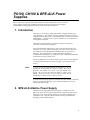
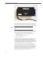
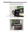
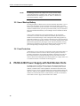
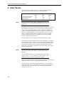
PS100, CH100 and BPE-ALK
Power Supplies
User Guide
Issued 12.12.12
Copyright © 2001-2012 Campbell Scientific Ltd.
CSL 274
Guarantee
This equipment is guaranteed against defects in materials and workmanship.
This guarantee applies for twelve months from date of delivery. We will
repair or replace products which prove to be defective during the guarantee
period provided they are returned to us prepaid. The guarantee will not apply
to:
•
Equipment which has been modified or altered in any way without the
written permission of Campbell Scientific
•
Batteries
•
Any product which has been subjected to misuse, neglect, acts of God or
damage in transit.
Campbell Scientific will return guaranteed equipment by surface carrier
prepaid. Campbell Scientific will not reimburse the claimant for costs incurred
in removing and/or reinstalling equipment. This guarantee and the Company’s
obligation thereunder is in lieu of all other guarantees, expressed or implied,
including those of suitability and fitness for a particular purpose. Campbell
Scientific is not liable for consequential damage.
Please inform us before returning equipment and obtain a Repair Reference
Number whether the repair is under guarantee or not. Please state the faults as
clearly as possible, and if the product is out of the guarantee period it should
be accompanied by a purchase order. Quotations for repairs can be given on
request. It is the policy of Campbell Scientific to protect the health of its
employees and provide a safe working environment, in support of this policy a
“Declaration of Hazardous Material and Decontamination” form will be
issued for completion.
When returning equipment, the Repair Reference Number must be clearly
marked on the outside of the package. Complete the “Declaration of
Hazardous Material and Decontamination” form and ensure a completed copy
is returned with your goods. Please note your Repair may not be processed if
you do not include a copy of this form and Campbell Scientific Ltd reserves
the right to return goods at the customers’ expense.
Note that goods sent air freight are subject to Customs clearance fees which
Campbell Scientific will charge to customers. In many cases, these charges are
greater than the cost of the repair.
Campbell Scientific Ltd,
Campbell Park, 80 Hathern Road,
Shepshed, Loughborough, LE12 9GX, UK
Tel: +44 (0) 1509 601141
Fax: +44 (0) 1509 601091
Email: [email protected]
www.campbellsci.co.uk
PLEASE READ FIRST
About this manual
Please note that this manual was originally produced by Campbell Scientific Inc. primarily for the
North American market. Some spellings, weights and measures may reflect this origin.
Some useful conversion factors:
Area: 1 in2 (square inch) = 645 mm2
Length:
1 in. (inch) = 25.4 mm
1 ft (foot) = 304.8 mm
1 yard = 0.914 m
1 mile = 1.609 km
Mass:
1 oz. (ounce) = 28.35 g
1 lb (pound weight) = 0.454 kg
Pressure:
1 psi (lb/in2) = 68.95 mb
Volume:
1 UK pint = 568.3 ml
1 UK gallon = 4.546 litres
1 US gallon = 3.785 litres
In addition, while most of the information in the manual is correct for all countries, certain information
is specific to the North American market and so may not be applicable to European users.
Differences include the U.S standard external power supply details where some information (for
example the AC transformer input voltage) will not be applicable for British/European use. Please
note, however, that when a power supply adapter is ordered it will be suitable for use in your country.
Reference to some radio transmitters, digital cell phones and aerials may also not be applicable
according to your locality.
Some brackets, shields and enclosure options, including wiring, are not sold as standard items in the
European market; in some cases alternatives are offered. Details of the alternatives will be covered in
separate manuals.
Part numbers prefixed with a “#” symbol are special order parts for use with non-EU variants or for
special installations. Please quote the full part number with the # when ordering.
Recycling information
At the end of this product’s life it should not be put in commercial or domestic refuse
but sent for recycling. Any batteries contained within the product or used during the
products life should be removed from the product and also be sent to an appropriate
recycling facility.
Campbell Scientific Ltd can advise on the recycling of the equipment and in some cases
arrange collection and the correct disposal of it, although charges may apply for some
items or territories.
For further advice or support, please contact Campbell Scientific Ltd, or your local agent.
Campbell Scientific Ltd, Campbell Park, 80 Hathern Road, Shepshed, Loughborough, LE12 9GX, UK
Tel: +44 (0) 1509 601141 Fax: +44 (0) 1509 601091
Email: [email protected]
www.campbellsci.co.uk
Contents
1. Introduction ........................................................................ 1
2. BPE-ALK Alkaline Power Supply ...................................... 1
3. PS100 Lead-Acid Power Supply ....................................... 3
3.1 Description ......................................................................................................... 3
3.2 AC Adapters (Transformers) ............................................................................. 6
3.2.1 AC-ADAPT ............................................................................................. 6
3.2.2 AC-ADAPT2 ........................................................................................... 6
3.2.3 Installation of the Adapter........................................................................ 7
3.3 Installation of the Power Supply Unit................................................................ 7
3.4 Charging ............................................................................................................ 9
3.5 Use of Backup Battery ..................................................................................... 10
3.6 Fuse Protection ................................................................................................ 10
4. PS100-A100 Power Supply with Null Modem Ports ...... 10
5. A105 12V Terminal Expansion Adapter .......................... 11
6. Solar Panels ...................................................................... 12
Figures
1. PS100 Power Supply with optional A100 null modem port fitted ..................... 3
2. CH100 Charger mounted alongside a BP24 in a typical logger-enclosure
configuration ................................................................................................... 4
3. Wiring to Charger ............................................................................................... 8
4. Simplified Charging Circuit Schematic .............................................................. 8
5. Null Modem Connections ................................................................................. 11
6. A105 Adapter.................................................................................................... 11
Tables
1. Typical Alkaline Battery Service as a Function of Temperature ........................ 3
2. Specifications ...................................................................................................... 5
3. Typical Battery Capacity for Lead-acid Batteries as a Function
of Temperature ................................................................................................ 6
4. Solar Panel Specifications ................................................................................ 12
PS100, CH100 & BPE-ALK Power
Supplies
Please refer to the relevant instruction manual for further information on the use of these
power supplies with specific Campbell Scientific equipment. Details of our intelligent
PS200/CH200 Charging Regulators are described in a separate manual.
1. Introduction
The PS100 is a 12-volt power supply that includes a charging regulator and a
7 amp hour battery. The CH100 is a charging regulator that is used with larger
Campbell Scientific battery packs such as the BP12, BP17 or BP24 or with a usersupplied battery. Charging power is typically supplied by an AC transformer or
an unregulated solar panel.
The PS100 and CH100 each have one adapter connector that will allow
connecting one of the following adapters.
The A100 Null Modem Adapter has two 9-pin connectors that provide a null
modem for use in a site, without a datalogger. The A100 connects and powers
two Campbell Scientific peripherals that would normally be connected to a
datalogger. These peripherals are typically modems linking different
communications technologies; e.g., telephone to radio. A PS100 sold fitted with a
A100 adaptor is sold as a PS100-A100.
The A105 Additional 12 V Terminals Adapter may be used to provide additional
12 V and ground terminals where the power supply is used to power several
devices.
NOTE
To prevent people from getting burned, an ABS plastic cover [CSI
#18688] sits on the heatsink of a PS100 or CH100. The cover is
fastened to the heatsink via a #4-40 x .250 Pan Phillips screw
[#395]. The cover must be removed to attach an A100 or A105
adapter. Some early models of the PS100 and CH100 did not
include the cover and do not have a place to attach it.
A number of Power Supply options are available with either alkaline or lead-acid
batteries. A unit that has the suffix -ALK to denote the battery type is a nonrechargeable alkaline supply.
2. BPE-ALK Alkaline Power Supply
The BPE-ALK has eight alkaline D-cells mounted in a simple carrier. The
BPE-ALK can also be used with a lead-acid battery connected in parallel to the
datalogger; in this case the alkaline batteries act as a backup. The BPE-ALK
incorporates a low voltage drop diode which prevents any paralleled battery
discharging into the alkaline batteries.
1
PS100, CH100 & BP-ALK Power Supplies
Before installing the alkaline batteries, connect all necessary sensor leads, control
lines and power leads. The datalogger can be turned off and on by disconnecting
and reconnecting the in-line connector between the BPE-ALK and the datalogger.
NOTE
The battery connector and in-line connectors fitted to all power
supply variants are 2-pole versions of the Molex Mini-Fit Jnr.
series.
You can remove and replace battery packs from all current dataloggers without
losing your stored program or data. However, if you wish to replace the batteries
without interrupting a current running program, do the following:
1.
Connect an external battery directly to the datalogger 12V terminals.
2.
Remove the old batteries.
3.
Replace with new alkaline D-cell batteries.
4.
Remove the external battery.
Where this is to be done on a regular basis a second, spare alkaline battery pack
can be bought. Each pack is supplied with a spare set of connection leads
including a mating connector and free end for wiring into the datalogger. This free
end can be detached and permanently wired into the datalogger resulting in two
connectors attached to the datalogger. To change the battery pack, simply plug the
new pack into the spare battery connector and remove the old one.
A fresh set of eight alkaline D cells provides 12.4V to the datalogger with a
nominal rating of 10Ah capacity at 20°C. The amp-hour rating decreases with
temperature, as shown in Table 1. The battery voltage can be monitored by using
the appropriate datalogger programming instruction. Please note that this will be
approximately 0.3V less than the actual battery voltage because of the diode
incorporated in the battery carrier. Replace the alkaline cells before the battery
voltage (as seen at the datalogger terminals) drops below 9.6V.
2
User Guide
Table 1 Typical Alkaline Battery Service as a Function of Temperature
Temperature (°C)
20 - 50
15
10
5
0
-10
-20
-30
NOTE
% of 20°C Service
100
98
94
90
86
70
50
30
This data is based on one ‘D’ cell under conditions of 50mA current
drain with a 30 ohm load. As the current drain decreases, the percent
service improves for a given temperature.
3. PS100/CH100 Lead-Acid Power Supplies
3.1 Description
The PS100 power supply includes a 12V, 7.0Ah lead-acid battery and a
temperature-compensated charging circuit. The unit can be fitted with optional
modules, such as the A100 null modem adaptor (see section 5).
Figure 1 PS100 Power Supply with optional A100 null modem port fitted
This supply is designed to power the datalogger continuously. Therefore, an AC
transformer (optional) or solar panel should be connected to the PS100 at all
times. The charging source powers the datalogger while float charging the leadacid batteries. The internal lead-acid battery powers the datalogger if the charging
source is interrupted.
NOTE
To prevent people from getting burned, an ABS plastic cover sits on
the heatsink of a PS100 or CH100. The cover is fastened to the
heatsink via a #4-40 x .250 Pan Phillips screw [#395]. The cover
must be removed to attach an A100 or A105 adapter. Some early
models of the PS100 and CH100 did not include the cover and do
not have a place to attach it.
3
PS100, CH100 & BP-ALK Power Supplies
The CH100 has an identical charging circuit to the PS100 but does not include an
attached battery carrier or battery (see Figure 2). It is commonly used with the
BP12, BP17 or BP24 battery packs or an external battery. The BP packs comprise
a carrier to hold the supplied lead acid battery onto the chassis plate of an
enclosure. The CH100 is generally mounted alongside the BP on the chassis plate.
CH100
charger/regulator
BP17
Figure 2(a) CH100 charger mounted alongside a BP17 in a typical loggerenclosure configuration
Figure 2(b) CH100 charger mounted alongside a BP17 in a typical loggerenclosure configuration
4
User Guide
The PS100 and CH100 specifications are given in Table 2, and the performance of
the battery with temperature is given in Table 3.
Table 2 Specifications
Lead-Acid Battery fitted to the PS100
Battery Type:
Float Life @ 25°C:
Shelf Life, full charge:
Yuasa NP7-12
5 years typical
Check twice yearly
Dimensions (H x W x D)
PS100:
CH100:
70 x 190 x 80 mm
102 x 70 x 39 mm
Weight
PS100:
CH100:
3.1 kg
158 g
Charger circuit (applies to CH100 too)
Charge technique:
Fixed voltage 14V nominal (varies
with temperature)
Charge Time (AC Source):
40 hr full charge, 20 hr 95% charge
(7Ah battery, longer for larger
batteries)
Maximum charger input voltage:
25V DC or 22V AC (RMS)
Maximum sustainable charge current
with unlimited current input (@ 25°C
18V input, 14V output):
1.2A typical
Maximum output current to
Terminal from battery & charger:
12V, 1.85A
Minimum voltage drop from charge
input to battery:
2.8V
Recommended minimum charge voltage:
17V at 25°C
AC-ADAPT Transformer
Input:
Isolated Output:
230V AC, 50Hz
18V AC @ 1.2A max.
AC-ADAPT2 Transformer
Input:
Isolated Output:
230V AC, 50Hz
18V AC @ 2A max.
Standalone Battery Packs typically used with CH100
Operating Temperature Range:
-40 to +60°C
BP12
12 Amp hours
BP17
17 Amp hours
BP24
24 Amp hours
5
PS100, CH100 & BP-ALK Power Supplies
Table 3 Typical Battery Capacity for Lead-acid Batteries
as a Function of Temperature
Temperature
(°C)
% of 20°C
capacity
NP7-12
40
110
7.7
20
100
7
0
84
5.9
-20
72
5.0
N.B. these figures only apply to low discharge rates.
CAUTION
Capacity (Ah)
NP12-12
13.2
12
10.0
8.6
NP17-12
18.7
17
14.2
12.2
NP24-12
26.4
24
20.2
17.3
It is recommended that the batteries should not be deeply
discharged below -20°C as there is a risk of ice formation
within the battery which can cause permanent damage.
3.2 AC Adapters (Transformers)
Two different 230V adapters are available from Campbell Scientific Limited in
Europe for use with the lead-acid power supply units. They have different
characteristics in use as explained below. Adaptors with different AC supply
voltages are available to special order.
3.2.1 AC-ADAPT
The AC-ADAPT is only suited for desktop use in low current applications. It can
provide up to 1.2A. If the transformer unit overheats, which is only likely to occur
if the output is short circuited, a safety mechanism will shut it down. In this
unlikely event, reset the safety mechanism manually by removing AC power,
tracing and eliminating the cause of the short circuit, and allowing the transformer
to cool before re-connecting to the mains supply.
The AC-ADAPT is provided with a fixed length of cable on the output side. Many
installations will require this cable to be extended using a suitable length of
compatible cable and an in-line connector. This extension cable is not supplied by
Campbell Scientific unless specifically ordered.
3.2.2 AC-ADAPT2
The AC-ADAPT2 transformer is suitable for permanent installations which
require a wall mounted unit. It is capable of providing more current than the
charger unit needs and so is able to recharge batteries at the maximum rate, and
still provide high current levels to equipment via the power supply. If the
transformer unit overheats, which is only likely to occur if the output is short
circuited, a safety mechanism will shut it down. In this unlikely event, reset the
safety mechanism manually by removing AC power, tracing and eliminating the
cause of the short circuit, and allowing the transformer to cool before reconnecting to the mains supply.
The AC-ADAPT2 is not provided with output cable unless specifically ordered.
The adapter is fitted with two screw-down terminals for you to connect a suitable
length of cable as required for your application. To fit the cable to the
6
User Guide
AC-ADAPT2, simply strip an appropriate length of the cable sheath, and secure
the wire under the screw terminals.
3.2.3 Installation of the Adapter
All low voltage power cables should have two cores at least 22SWG (0.71mm)
thick. You may find that standard AC power cable is suitable. The cable run from
the AC adapter to the charger module can be extended for several hundred metres
if necessary, but if high current demands are anticipated, use thicker cable to
prevent significant voltage drop.
If the cable runs through areas where there might be a chance of electromagnetic
interference, the use of a screened cable is advised, where the screen is connected
at one end only (for example to the enclosure grounding point).
When installing the cable within an enclosure, it is best to route the power input
cables as far as possible from the signal cables in order to avoid noise injection
into the signal cables. It may also be advisable to use screened power cable if high
current is being taken from the AC-ADAPT2, as the current flowing in the power
cable will cause radiation of 50Hz noise.
CAUTION
For safety reasons, both the AC-ADAPT and AC-ADAPT2
adapters should always be installed in a dry, condensationfree environment. Where the AC supply is some distance
from the datalogger installation, it is recommended that the
AC adapter is mounted in a dry situation adjacent to the AC
power outlet, and only the safer, low-voltage, cable is
extended from the adapter to the datalogger enclosure.
3.3 Installation of the Power Supply Unit
The power supply units are designed to be mounted on a chassis plate using the
four corner mounting holes. Fittings are provided for mounting to a Campbell
Scientific enclosure chassis. To avoid damage during shipping, lead-acid batteries
are sometimes packed separately. Install the battery into the carrier and connect
the battery lead to the battery connector on the charger unit, or, if no charger is
being used, connect to the appropriate in-line power connector. You should also
check the integrity of any in-line power connectors and the power plug on the
datalogger itself before powering up the system.
When attaching wires to a CH100 charger module, allow enough spare wire to
ensure easy removal of the battery at a later date.
7
PS100, CH100 & BP-ALK Power Supplies
To Battery
From Transformer
or Solar Panel
To Datalogger
or Peripherals
Figure 3. Wiring to Charger
BATT
INT
EXT
CHG
Regulator
IN
3A
Thermal
Fuse
ON
OUT
OFF
Charging
CHG
CHG
+12
+12
Figure 4. Simplified Charging Circuit Schematic
8
These look
identical
when
unplugged
User Guide
3.4 Charging
The 12 volt and ground terminals on the power supplies are for supplying power
to the datalogger or other 12 volt devices. A lead is supplied fitted with an in-line
connector to connect to such a device. The in-line connector is the method of
turning off power to the datalogger.
The two terminals labelled ‘CHARGE’ are for connecting an AC adapter or solar
panel to charge the lead-acid batteries. The charge input can be either AC or DC,
and it does not matter which terminal is positive or negative. The voltage input
must be within the range 16 to 26V DC, or 16 to 26V AC RMS. A transzorb
provides transient protection to the charging circuit. A sustained input voltage in
excess of 40V will cause the transzorb to limit voltage.
Some solar panels and AC adapters are supplied fitted with a connector. This
connector must be cut off so that the two wires can be inserted directly into the
two CHARGE terminals.
The red light (LED) on the charger unit comes on when an external charging
supply is connected.
NOTE
NOTE
Illumination of this LED does not guarantee that there is sufficient
charge entering the battery to stop the battery discharging; it only
indicates successful connection of the charging source.
If the battery is fully charged first, it may be stored for up to six months.
A battery that has been stored without charging should be given a ‘top-up
charge’ by charging it in its carrier/charger unit from an AC source for
one day before being placed into service.
There are inherent hazards associated with the use of sealed lead-acid batteries.
Under normal operation, lead-acid batteries generate only a very small amount of
hydrogen gas. This gaseous by-product is generally insignificant because the
hydrogen dissipates naturally before build-up to an explosive level (4%) occurs.
However, if the batteries are shorted or overcharging takes place, hydrogen gas
may be generated at a rate sufficient to create a hazard. Campbell Scientific
therefore makes the following recommendations:
WARNING
A PS100 or any supply equipped with lead-acid batteries
should never be used in applications requiring
intrinsically safe equipment and should not be housed in
a gas-tight enclosure.
Campbell Scientific’s ENC 10/12 and 12/14 enclosures are supplied fitted with a
porous vent plug in a cable gland on the base of the enclosure. It is recommended
that this is left in place when using a lead-acid battery as it will prevent pressure
build-up in the event of gas release from the battery.
It is recommended that the battery voltage is monitored using the appropriate
datalogger programming instruction. Add this instruction to your programs to
keep track of the state of the power supply. If the system voltage level consistently
decreases, some element(s) of the charging system has failed or the charging
source is not providing adequate current. It should be noted though that the
terminal voltage of lead-acid batteries varies with temperature.
9
PS100, CH100 & BP-ALK Power Supplies
NOTE
The datalogger measures the voltage at its 12V port, not the voltage
of the lead-acid battery. External power sources must therefore be
disconnected from the charging circuit in order to measure the
actual lead-acid battery voltage.
3.5 Use of Backup Battery
The charger/regulator is fitted with two connectors labelled ‘BATTERY’. One of
these sockets is normally used for connection of the internal battery. The other
socket is provided mainly for the connection of a secondary backup battery, which
could be an alkaline battery pack. This pack would normally only be connected to
allow the internal lead-acid battery to be exchanged. The two terminals are diode
protected.
Under certain circumstances a larger lead-acid battery can be permanently
connected to one of these sockets, with the internal battery disconnected. You
should be aware that the charger circuit is designed for float charging relatively
small lead-acid batteries. Trying to recharge a discharged, large external lead-acid
battery may be successful but will result in a very slow rate of charge and a certain
amount of heat generation by the charger circuit. If the external battery is being
discharged at a significant rate, then current limiting circuits in the charger may
prevent enough charge reaching the battery to keep it fully charged.
3.6 Fuse Protection
A thermal fuse (1.85A) in the power circuit limits current flow from the battery to
the 12V terminal. If excessive current is drawn, the fuse gets hot, increases in
resistance, and limits the current. When the problem is fixed, the fuse cools and
the resistance decreases, eventually allowing current to pass. When excessive
current is drawn due to shorting the power leads together, for example, allow 10 to
15 seconds for the fuse to cool before reconnecting power.
4.
PS100-A100 Power Supply with Null Modem Ports
The PS100-A100 12V Lead-Acid Power Supply with Charging Regulator and
Null Modem Ports (see Figure 1) is used when 5V is needed to power external
modems, in addition to the normal capabilities of the PS100. The PS100-A100
supplies 5V to pin 1 of two 9-pin null modem ports, which protrude from the side
of the case. Otherwise the capabilities and functions are identical to the PS100. A
common use for the PS100-A100 is in radio telemetry networks. The maximum
current drain on the 5V supply of the PS100-A100 is 150mA.
10
User Guide
Figure 5. Null Modem Connections
CAUTION
This cannot be used as a null modem between two RS232 devices.
5. A105 12V Terminal Expansion Adapter
The A105 adapter adds four 12-V terminals and four ground terminals to a CH100
or PS100 (see Figure 6). The extra terminals make it easier to wire multiple
continuously powered 12-Vdc devices to the power supply.
Figure 6. A105 Adapter
11
PS100, CH100 & BP-ALK Power Supplies
6. Solar Panels
Auxiliary photovoltaic power sources such as the SP5, SP10 and SP20 Solar
Panels may be used to maintain the charge on lead-acid batteries.
Table 4 Solar Panel Specifications
Typical Peak Power (Watts)
Current @ Peak (Amps)
Amp Hrs/week
NOTE
SP5
4.5
0.27
6.4
SP10
10
0.58
14.4
SP20
20
1.17
26.4
These specifications assume 1kW/m2 illumination at a panel cell
temperature of 25°C. Individual panel performance may vary as
much as 10%.
When selecting a solar panel, a rule-of-thumb is that on a stormy overcast day the
panel should provide enough charge to meet the system current drain (assume
10% of average annual global radiation, kW/m2). Specific site information, if
available, could strongly influence the solar panel selection. For example, local
effects such as mountain shadows, fog from valley inversion, snow, ice, leaves,
birds, etc. shading the panel should be considered. Please refer to Campbell
Scientific Technical Note 12 for a more detailed analysis of how to estimate
power consumption and solar panel size.
The SP5 and SP10 are most commonly used with the PS100 power supply.
The SP20 can also be used with the PS100 in many circumstances – for example,
in less favourable climatic conditions, and in some Northern installations, where
solar radiation can be low. It can also be used in some high current applications,
but it should be noted that the reserve capacity of the PS100 battery may be a
limiting factor. The CH100 or CH200 plus a large capacity battery pack is better
suited to such applications.
NOTE
The SP20 or large panels when connected to the PS100, must not be
used to charge a large external battery in parallel with the internal 7
Ah battery.
Note also that the SP20R (the version of the SP20 fitted with a shunt
regulator) must not be connected to these chargers. This
combination will not result in successful battery charging.
Please see the Solar Panels User Guide (supplied with orders for solar panels from
Campbell Scientific) for further installation and technical details.
If you intend to use solar panels from other manufacturers (i.e. not supplied by
Campbell Scientific), choose a panel which gives its optimum power output at a
voltage greater than 16V. Some cheaper 12V panels show a sharp decline in
efficiency above 14V DC.
12
CAMPBELL SCIENTIFIC COMPANIES
Campbell Scientific, Inc. (CSI)
815 West 1800 North
Logan, Utah 84321
UNITED STATES
www.campbellsci.com • [email protected]
Campbell Scientific Africa Pty. Ltd. (CSAf)
PO Box 2450
Somerset West 7129
SOUTH AFRICA
www.csafrica.co.za • [email protected]
Campbell Scientific Australia Pty. Ltd. (CSA)
PO Box 444
Thuringowa Central
QLD 4812 AUSTRALIA
www.campbellsci.com.au • [email protected]
Campbell Scientific do Brazil Ltda. (CSB)
Rua Luisa Crapsi Orsi, 15 Butantã
CEP: 005543-000 São Paulo SP BRAZIL
www.campbellsci.com.br • [email protected]
Campbell Scientific Canada Corp. (CSC)
11564 - 149th Street NW
Edmonton, Alberta T5M 1W7
CANADA
www.campbellsci.ca • [email protected]
Campbell Scientific Centro Caribe S.A. (CSCC)
300N Cementerio, Edificio Breller
Santo Domingo, Heredia 40305
COSTA RICA
www.campbellsci.cc • [email protected]
Campbell Scientific Ltd. (CSL)
Campbell Park
80 Hathern Road
Shepshed, Loughborough LE12 9GX
UNITED KINGDOM
www.campbellsci.co.uk • [email protected]
Campbell Scientific Ltd. (France)
3 Avenue de la Division Leclerc
92160 ANTONY
FRANCE
www.campbellsci.fr • [email protected]
Campbell Scientific Spain, S. L.
Avda. Pompeu Fabra 7-9
Local 1 - 08024 BARCELONA
SPAIN
www.campbellsci.es • [email protected]
Campbell Scientific Ltd. (Germany)
Fahrenheitstrasse13, D-28359 Bremen
GERMANY
www.campbellsci.de • [email protected]
Please visit www.campbellsci.com to obtain contact information for your local US or International representative.