1
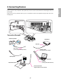
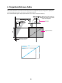
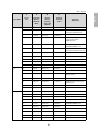
Installation Guide
Safety Instructions
For your safety, read all the instructions in this guide before using the mounting bracket. Incorrect handling
that ignores instructions in this guide could damage the mounting bracket or could result in personal injury or
property damage. Keep this installation guide at hand for future reference.
Read the User's Guide and Safety Instructions for your projector and follow the instructions in these
documents.
Explanation of Symbols
The warning marks shown below are used throughout this installation guide to prevent personal injury or
property damage. Make sure you understand these warnings when reading this installation guide.
Warning
This symbol indicates information that, if ignored, could possibly result in personal injury or even death
due to incorrect handling.
Caution
This symbol indicates information that, if ignored, could possibly result in personal injury or physical
damage due to incorrect handling.
Symbol indicating an action that must not be done
Symbol indicating an action that should be done
Safety Precautions for Installation
Warning
The mounting bracket is designed specifically for mounting a projector to a wall. If anything other than a
projector is mounted, the weight may result in damage.
If the mounting bracket falls, it could cause personal injury or property damage.
The installation work (wall mounting) should be performed by specialists who have technical knowledge
and ability. Incomplete or incorrect installation could cause the mounting bracket to fall and cause
personal injury or property damage. Contact the customer support office listed on the Epson Projector
Contact List in the User's Guide for your projector when installing the mounting bracket.
Follow the instructions in this guide when installing the mounting bracket.
If the instructions are not followed, the mounting bracket may fall, resulting in personal injury or an accident.
Handle the power cable carefully.
Incorrect handling may cause fire or electric shock. Observe the following precautions when handling:
• Do not handle the power plug with wet hands.
• Do not use a power cable that is damaged or modified.
• Do not pull the power cable with too much force when routing the cable through the mounting bracket.
When you mount the projector on the wall with the mounting bracket, the wall requires enough strength to
hold the projector and the mounting bracket. Confirm the mass of the projector and the mounting bracket
before installation, and maintain the strength of the wall. If the wall is not strong enough, reinforce the
wall before installation.
Do not install the mounting bracket in a place where it might be subjected to vibration or shock.
Vibration or shock could cause damage to the projector or mounting surface. It could also cause the mounting bracket or
projector to fall and cause personal injury or property damage.
Install the mounting bracket so that it can sufficiently support the mass of the projector and mounting
bracket, and resist any horizontal vibration. Use M8 nuts and bolts.
Nuts and bolts smaller than M8 could cause the mounting bracket to fall. Epson takes no responsibility for any damage or
injury caused by incorrect installation.
2
The installation work should be performed by at least two qualified service personnel. If you need to
loosen any screws during installation, be careful not to drop the mounting bracket.
If the mounting bracket or projector falls, it could cause personal injury or property damage.
Inspect the mounting bracket on a regular basis to ensure there are no broken parts or loose screws.
If there are any broken parts, stop using the mounting bracket immediately. If the mounting bracket or projector falls, it
could cause personal injury or property damage.
Never modify the mounting bracket.
Do not hang on the mounting bracket or hang a heavy object on the mounting bracket.
If the projector or mounting bracket falls, it could cause personal injury or property damage.
If you use adhesives to prevent the screws from loosening or things such as lubricants or oils on the slide
plate fixing part of the projector, the case may crack and cause the projector to fall, resulting in personal
injury or property damage. Do not use adhesives, lubricants, or oils to install or adjust the mounting
bracket.
Tighten all screws firmly after adjustment.
If the screws are not tightened firmly, the projector or mounting bracket may fall and cause personal injury or property
damage.
Never loosen the bolts and nuts after installation.
Confirm that the screws have not become loose on a regular basis. If you find any loose screws, tighten them firmly. If the
screws are not tightened firmly, the projector or mounting bracket may fall and cause personal injury or property
damage.
Caution
Do not install the mounting bracket in a location where the operating temperature for your projector
model may be exceeded.
Such an environment may damage the projector.
Install the mounting bracket in a place free from excessive dust and humidity to prevent the lens or optical
components from becoming dirty.
Do not use excessive force when adjusting the mounting bracket.
The mounting bracket may break, resulting in personal injury.
Place to Install the Mounting Bracket
Carry out the power supply wiring work for the installation location of the mounting bracket in advance.
Install the projector away from other electric devices such as fluorescent lights or air conditioners. Some
kinds of fluorescent lights could interfere with the remote control of the projector.
It is recommended to keep connection cable length less than 20 meters to reduce external noise.
Install the mounting bracket in a place free from excessive dust and humidity to prevent the lens or
optical components from becoming dirty.
About This Installation Guide
This guide describes how to mount the short-throw projector EB-460i/460/450Wi/450W/440W to a wall using
the exclusive mounting bracket.
3
English
Warning
1
Package Contents
s Page 5
2
Specifications
s Page 6
3
Connecting Devices
s Page 7
4
Projection Distance Table
s Page 8
5 Installation Procedure
(1)
(2)
(3)
(4)
(5)
s Page 10
Install the wall plate on the wall
Determine the projection distance and pull out the slider
Attach the mounting bracket to the wall plate
Secure the projector to the mounting bracket
Connect the power cable and other cables to the projector
6 Adjusting the Projection Screen
(1)
(2)
(3)
(4)
(5)
(6)
(7)
(8)
(9)
(10)
s Page 14
Turn on the projector
Change the aspect ratio
Display the test pattern
Adjust the focus
Use the top adjustment dial to adjust the vertical tilt
Use the right adjustment dial to adjust the horizontal rotation
Use the left adjustment dial to adjust the horizontal roll
Adjust the vertical slide
Adjust the forward/backward slide
Turn off the display of the test pattern
7 Attaching the Covers
s Page 18
(1) Attach the wall plate cover and end cap
(2) Attach the cable cover to the projector
4
English
1. Package Contents
Wall plate
Mounting bracket
End cap
Wall plate cover
Template sheet
(for installing the wall plate)
Shape
Hexagon wrenches (for M4, M5, and M8)
Name
Quantity
Application
M8 x 35 mm hexagon socket head cap bolt without
washer
2
For installing/adjusting mounting
bracket
M8 x 15 mm hexagon socket head cap bolt with
washer
2
For installing mounting bracket
M5 x 12 mm hexagon socket head cap bolt with
washer
2
For securing projector
M4 x 12 mm hexagon socket head cap bolt without
washer
2
For installing wall plate cover
Use the bolts supplied with the mounting bracket to install it, as directed in this guide. Do not substitute
these bolts with any other types.
Use commercially available M8 x 50 mm anchors (at least 3) or 8 x 80 mm lag bolts (at least 3) to attach the
wall plate to the wall.
Gather the tools and parts you need before you begin installation.
5
2. Specifications
Item
Specification
Remark
Reference Page
Mounting bracket mass
Approx. 6.3 kg
(13.89 lb.)
Wall plate (2.2 kg [4.85 lb.])
Covers and cap (0.47 kg [1.04 lb.])
Forward/backward slide
adjustment range
0 to 300 mm
(11.81 in.)
Vertical slide adjustment range
± 4°
Minimum: 28 mm (1.10 in.)
Maximum: 42.5 mm (1.67 in.)
s
p. 17
Vertical tilt adjustment range
± 5°
Fine adjustments possible with adjustment dial
s
p. 15
Horizontal rotation adjustment
range
°
±5
Fine adjustments possible with adjustment dial
s
p. 16
Horizontal roll adjustment range
± 3°
Fine adjustments possible with adjustment dial
s
p. 16
Horizontal slide adjustment range
± 45 mm
(1.77 in.)
Refer to the figure
below
Refer to the figure
below
Wall plate
[Unit: mm (in.)]
Mounting bracket adjustment range
Forward/backward slide adjustment range:
0 to 300 mm (11.81 in.)
Horizontal slide adjustment range:
± 45 mm (1.77 in.)
6
Prepare a power cable, computer cable, USB cable, and so on at the location where the mounting bracket is to
be installed.
Prepare all necessary cables for devices, such as a document camera or microphone, that you will connect to
the projector.
Connection Example
External speakers
LAN device
LAN cable
Audio cable
(commercially available product)
Computer cable
(for computer video output)
Microphone
Computer
USB cable
(for Easy Interactive Function)
Document camera
Dedicated USB cable
(supplied with document camera)
7
English
3.Connecting Devices
4. Projection Distance Table
Refer to the table below and install the mounting bracket and projector to project images at an appropriate
size on the projection surface. The values are only rough estimates.
The recommended range for the projection distance (a) is 7 to 37 cm (2.76 to 14.57 in.).
65 mm (2.55 in.)
Offset value for the position of
the center of the screen and the
center of the wall plate
240 mm (9.44 in.)
Wall plate
Projection surface
Distance from wall of
projection surface
WXGA
XGA
16
4
3
S
8
9
Aspect Ratio
4:3
S
a
b
h
Screen
Size
Projection
Distance
Minimum
(Wide)
Distance
Between
Projection
Surface and
Wall Plate
Height of
Projection
Surface
Interactive
Whiteboard
63"
71 (2.80)
175 (6.89)
960 (37.80)
Hitachi StarBoard FX-63
64"
79 (3.11)
177 (6.97)
975 (38.39)
SMART Board 660
Promethean ActivBoard 164
70"
125 (4.92)
191 (7.52)
1067 (42.01)
77"
178 (7.00)
207 (8.15)
1173 (46.18)
Hitachi Cambridge Board 77
Hitachi StarBoard FX-77
SMART Board 680
77.5"
182 (7.16)
208 (8.19)
1181 (46.50)
RM ClassBoard2 77.5
INTERWRITE® BOARD 1077
16:10
16:9
78"
186 (7.32)
209 (8.23)
1189 (46.81)
80"
201 (7.91)
213 (8.39)
1219 (47.99)
87"
255 (10.03)
229 (9.02)
1326 (52.20)
90"
277 (10.90)
236 (9.29)
1372 (54.02)
100"
354 (13.93)
259 (10.20)
1524 (60.00)
102"
369 (14.52)
264 (10.39)
1554 (61.18)
60"
76 (2.99)
257 (10.12)
808 (31.81)
70"
157 (6.18)
294 (11.57)
942 (37.09)
78"
222 (8.74)
325 (23.39)
1050 (41.34)
80"
238 (9.37)
332 (13.07)
1077 (42.40)
87"
294 (11.57)
358 (14.09)
1171 (46.10)
90"
319 (12.55)
370 (14.57)
1212 (47.72)
96"
367 (14.44)
392 (15.43)
1292 (50.87)
58"
73 (2.87)
295 (11.61)
722 (28.43)
60"
90 (3.54)
304 (11.97)
747 (29.41)
65"
131 (5.15)
327 (12.87)
809 (31.85)
70"
173 (6.81)
350 (13.78)
872 (34.33)
71"
181 (7.12)
355 (13.98)
884 (34.80)
80"
256 (10.07)
396 (15.59)
996 (39.21)
82"
272 (10.70)
405 (15.94)
1021 (40.20)
Hitachi StarBoard FX-82W
85"
297 (11.69)
419 (16.50)
1058 (41.65)
INTERWRITE® BOARD 1085
90"
339 (13.34)
441 (17.36)
1121 (44.13)
93"
364 (14.33)
455 (17.91)
1158 (45.59)
9
PolyVision TS610
Promethean ActivBoard 178 / 378
PolyVision TS 600
/ TS610 / TSL610
SMART Board 685 / Promethean
ActivBoard 387
RM ClassBoard2 60
INTERWRITE® BOARD 1071
English
Unit: mm (in.)
5. Installation Procedure
Make sure to follow the steps below to install the mounting bracket. If you ignore these steps, the mounting
bracket could fall and cause personal injury or property damage.
The maximum combined mass of the mounting bracket and the projector is approximately 15.2
kg (33.5 lb). When you install the mounting bracket, calculate the permissible weight, carefully
check the construction, material, and strength of the wall, and perform the installation properly
using the most appropriate method.
A Install the wall plate on the wall
(1) Determine the template sheet position.
• From the projection distance table, confirm the screen size (S) and the distance between the
projection surface and wall plate (b).
• Align the CTR line (vertical) of the template sheet with the center line (vertical) of the projection
surface.
Confirm where the beams are within the wall, and shift the position left or right as necessary.
(The position can be shifted horizontally left or right from the center line of the projection surface by
up to 45 mm [1.77 in.].)
Align the line (horizontal) of the template with the height of (b).
65 mm (2.55 in.)
CTR line of template sheet
line of template sheet
Center line of projection surface
(2) Attach the template sheet to the wall.
10
The wall plate needs to be secured by commercially available anchors or lag bolts in the following
places. It is recommended that the wall plate be secured in at least three places.
• If securing the wall plate in four places, make the holes indicated by A or B in the figure.
• If securing the wall plate in three places, make the holes indicated by C in the figure.
Four mounting holes
Three mounting holes
(4) Remove the template sheet.
(5) Mount the wall plate on the wall.
Warning
❏
When you mount the projector on the wall with the mounting bracket, the wall needs to be
strong enough to hold the projector and the mounting bracket. Confirm the mass of the
projector and the mounting bracket before installation, and maintain the strength of the
wall. If the wall is not strong enough, reinforce the wall before installation.
❏
Install the mounting bracket so that it can sufficiently support the mass of the projector
and mounting bracket, and resist any horizontal vibration. Use M8 nuts and bolts. Nuts
and bolts smaller than M8 could cause the mounting bracket to fall.
❏
Epson takes no responsibility for any damage or injury caused by incorrect installation.
B Determine the projection distance and pull out the slider
(1) From the projection distance table, calculate the distance (a) from the projection surface to
the front of the projector.
(2) Loosen the four screws and pull out the slider on the mounting bracket.
Align the slider with the mark slider measure that is a distance (a+x) equivalent to the distance (a) plus
the thickness of the projection screen (x).
Screws (4 )
a+X
Slider measure
11
English
(3) Make mounting holes in the wall in the required locations.
C Attach the mounting bracket to the wall plate
(1) Hang the mounting bracket hook onto the wall plate bar (A).
(2) Lift up the mounting bracket and pass the cables through it (B).
Caution
Take care not to trap the cables between the mounting bracket and wall plate.
(3) Tighten the two M8 x 15 mm hexagon socket head cap bolts and two M8 x 35 mm hexagon
socket head cap bolts supplied with the mounting bracket so that the mounting bracket
becomes horizontal (C).
Use the two M8 x 35 mm hexagon socket head cap bolts to adjust the vertical slide.
s p. 17
Wall plate
Wall plate bar
Mounting bracket
Mounting bracket hook
Cables
M8 x 15 mm hexagon socket
head cap bolts (one on left
and one on right)
M8 x 35 mm hexagon
socket head cap bolts (2)
D Secure the projector to the mounting bracket
(1) Loosen the two screws and remove the cable cover from the projector.
Cable cover
Screws (2)
12
M5 x 12 mm hexagon
socket head cap bolts (2)
Side plate
Bolt positions
Projector
interface side
Marks
(3) Tighten the two M5 x 12 mm hexagon socket head cap bolts (C).
Warning
If you use adhesives to prevent the screws from loosening or things such as lubricants or oils
on the slide plate fixing part of the projector, the case may crack and cause the projector to fall,
resulting in personal injury or property damage. Do not use adhesives, lubricants, or oils to
install or adjust the mounting bracket.
E Connect the power cable and other cables to the projector
Connect any necessary cables such as the power cable, computer cable, and USB cable to the projector.
Power cable
Computer cable
USB cable
13
English
(2) Insert the slide plate into the mounting bracket from the interface side of the projector (A).
Align the marks on the projector and the mounting bracket (B).
6. Adjusting the Projection Screen
To ensure maximum projection screen quality, follow the steps below to adjust the projection screen.
Do not make adjustments with the Keystone function of the projector. Doing so may
result in a reduction in image quality.
A Turn on the projector
Using Remote Control
Using Control Panel
B Change the aspect ratio
Each time you press the [Aspect] button on the remote control, the aspect name is displayed on the
screen and the aspect changes.
Change the setting according to the signal for the connected equipment.
Remote Control
Aspect Ratio
4:3
Alternatively, set the aspect ratio from the [Signal] menu - [Aspect] from the Configuration menu.
s User’s Guide for the projector: [Configuration] menu - [Signal] menu
C Display the test pattern
Press the [Menu] button and select the [Settings] menu - [Pattern] - [Test Pattern] from the
Configuration menu.
s User’s Guide for the projector: [Configuration] menu - [Settings] menu
Using Remote Control
Using Control Panel
14
(1) Move the air filter cover lever to open the air filter cover.
(2) Use the focus lever to adjust the focus.
Air filter cover
Focus lever
(3) After you finish making the adjustment, close the air filter cover.
E Use the top adjustment dial to adjust the vertical tilt
Repeat steps
E to I as necessary.
(1) Loosen the screw that corresponds to the top adjustment dial (A).
(2) Turn the adjustment dial to adjust the vertical tilt (B).
(3) After you finish making all of the adjustments in steps
loosened in A.
15
E to I, tighten the screw you
English
D Adjust the focus
F Use the right adjustment dial to adjust the horizontal rotation
(1) Loosen the two screws that correspond to the right adjustment dial (A).
(2) Turn the adjustment dial to adjust the horizontal rotation (B).
(3) After you finish making all of the adjustments in steps
E to I, tighten the two screws you
loosened in A.
G Use the left adjustment dial to adjust the horizontal roll
(1) Loosen the screw that corresponds to the left adjustment dial (A).
(2) Turn the adjustment dial to adjust the horizontal roll (B).
(3) After you finish making all of the adjustments in steps
loosened in A.
16
E to I, tighten the screw you
Adjust the vertical slide with the two M8 x 35 mm hexagon socket head cap bolts at the bottom of the
mounting bracket. Tightening the bolts raises the mounting bracket, and loosening them lowers it.
The projection screen is raised or lowered accordingly.
M8 x 35 mm
hexagon socket
head cap bolts (2)
I Adjust the forward/backward slide
Loosen the four screws and adjust the slider of the mounting bracket.
Screws (4)
After you finish making all of the adjustments in steps
E to I, tighten the screws.
J Turn off the display of the test pattern
Press the [Esc] button on the remote control or control panel to turn off the test pattern.
Warning
Tighten all screws firmly. If the screws are not tightened firmly, the projector or mounting
bracket may fall and cause personal injury or property damage.
17
English
H Adjust the vertical slide
7. Attaching the Covers
A Attach the wall plate cover and end cap
(1) Secure the wall plate cover with the two M4 x 12 mm hexagon socket head cap bolts (A).
q
Depending on how the cables are wired, you may need to cut out parts of the wall
plate cover to allow the cables to be passed through it.
(2) Place the end cap with the concave portion facing up (B).
M4 x 12 mm
hexagon socket head
cap bolts (2)
Wall plate cover
End cap
B Attach the cable cover to the projector
Attach the cable cover and tighten the two screws to secure the cable cover.
Screws (2)
Cable cover
Only a specialist should remove or reinstall the projector, including for maintenance and
repairs. Refer to the User’s Guide of your projector for instructions on maintenance and repairs.
18
❏
Never loosen the bolts and nuts after installation. Confirm that the screws have not
become loose on a regular basis. If you find any loose screws, tighten them firmly. If the
screws are not tightened firmly, the projector or mounting bracket may fall and cause
personal injury or property damage.
❏
Do not hang on the mounting bracket or hang a heavy object on the mounting bracket. If
the projector or mounting bracket falls, it could cause personal injury or property damage.
8. Appendix
Using the Easy Interactive Function
After you install an Easy Interactive Function compatible model (EB-460i/450Wi), you need to install the Easy
Interactive Driver and perform calibration (to align the positions of the cursor and Easy Interactive Pen).
For details, refer to the supplied Quick Start Guide or the User’s Guide on the Document CD-ROM.
Attaching a Security Cable
If the projector is to be installed in a room where it will be left unattended, you can use a commercially
available theft-prevention wire lock to secure the projector to a post or other object to prevent someone from
taking it.
Pass the wire of the theft-prevention wire lock through the security cable installation point.
For details on how to lock the wire lock, refer to the User’s Guide supplied with the wire lock.
19
English
Warning
20
21
English