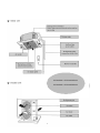
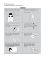
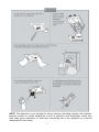
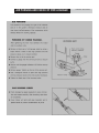
1
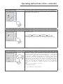
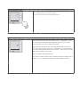
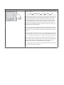
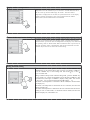
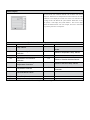
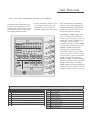
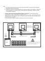
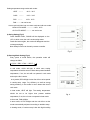
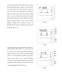
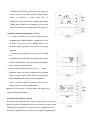
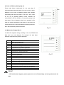
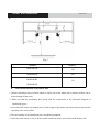
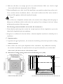
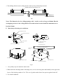
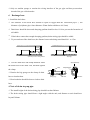
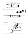
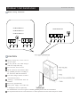
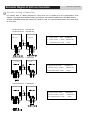
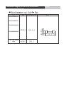
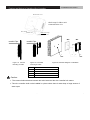
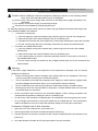
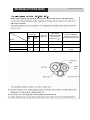
OWNER'S MANUAL
MANUAL
C & H A IR C O N D I T I O N E R S
Air Conditioner
CASSETTE SERIES
MODELS:
indoor unit
outdoor unit
GKH18K3BI
GUHN18NK3AO
GKH24K3BI
GUHN24NK3AO
GKH36K3BI
GUHN36NM3AO
GKH48K3BI
GUHN48NM3AO
Thanks for your selection of our Air-Conditioning Unit. Before use, please read this instruction
manual carefully and keep it properly to ensure correct use of this machine.
1. Names and functions of parts
GKH18K3BI / GUHN18NK3AO
GKH24K3BI / GUHN24NK3AO
1
GKH36K3BI / GUHN36NMK3AO
GKH48K3BI / GUHN48NMK3AO
2
2. Safety cautions
●Read the following carefully to assure safe use.
NOTE: Children should be supervised to ensure that they do not play with the appliance.
3
NOTE: This appliance is not intended for use by persons (including children) with reduced
physical, sensory or mental capabilities, or lack of experience and knowledge, unless they
have been given supervision or instruction concerning use of the appliance by a person
responsible for their safety.
4
Safety Considerations
Please read this manual carefully before use and operate correctly as instructed in the manual.
1
You are specially warned to note the two symbols below.:
WARNING! A symbol indicating that improper operation might cause human death or severe
injuries.
A symbol indicating that improper operation might cause human injury or property
damage.
WARNING!
●
●
This unit shall be used in the houses, offices, restaurants, residences or similar places.
Please seek an authorized repair station for installation work. Improper installation might cause water leakage,
electric shock or fire.
● Please install at a place strong enough to support the weight of air conditioner unit. If not, the air conditioner
unit might fall down and cause human injury or death.
● To ensure proper drainage, the drainage pipe shall be correctly installed according to installation instructions.
Take proper measures for heat preservation to prevent condensing. Improper installation of pipes might cause
leakage and wet the articles in the room.
● Do not use or store flammable, explosive, poisonous or other dangerous substances beside the air conditioner.
● In case of trouble (e.g. burnt smell), please immediately cut off the main power of air conditioner unit.
● Keep air flow to avoid shortage of oxygen in the room.
● Never insert your finger or any objects into air outlet and inlet grill.
● Never plug or unplug the power cable directly to start or stop the air-conditioning unit.
● Please take constant care to check if the mounting rack is damaged after long use.
● Never modify the air conditioner. Please contact the dealer or professional installation workers for repair or
relocation of the air conditioner.
● The appliance shall not be installed in the laundry.
WARNING!:
● The installation, cleaning and maintenance work must be done by a qualified person. Do not do such work by
yourself.
● Before installation, please check the power supply for compliance with the ratings on nameplate. Check the
power safety as well.
● Before use, please check and confirm if the cables, drainage pipes and pipelines are correctly connected,
hence to eliminate the risk of water leakage, refrigerant leakage, electric shock or fire.
● Main power must be securely earthed to ensure effective grounding of air conditioner unit and avoid the risk
of electric shock. Please do not connect the earthling cable to coal gas pipe, water pipe, lightning rod or
telephone line.
● Once started, the air conditioner shall not be stopped at least after 5 minutes or longer; otherwise the oil
return to compressor may be affected.
● Do not let the child to operate the air conditioner unit.
● Do not operate the air conditioner unit with wet hands.
● Please disconnect the main power before cleaning the air conditioner or replacing the air filter.(Operating by
professional)
● Please disconnect the main power if to put the air conditioner unit out of use for a long period.
● Please do not expose the air conditioner unit directly under corrosive environment with water or moisture.
● Please do not foot on or place any goods on air conditioner unit.
● After electrical installation, the air conditioner unit shall be energized for electrical leakage test.
● If the supply cord is damaged, it must be replaced by the manufacturer or its service agent or a similarly
qualified person in order to avoid a hazard .
● An all-pole disconnection switch having a contact separation of at least 3mm in all poles should be connected
in fixed wiring.
● The appliance shall be installed in accordance with national wiring regulations.
● The temperature of refrigerant circuit will be high, please keep the interconnection cable away from the per tube.
Wire controller (standard fitting)
SWING
SWING
TIMER
Composition of wire controller
9
1 Timing display
2
Fan speed display (Auto, High speed, Medium
speed, Low speed)
Failure st atus display
10
Sleep st atus display
11
Mode key
3 Defros ting st atus display
12
Se t temperatur e incr ease key
4 Ener gy saving st atus display
13
Se t temperatur e decr ease key
5 Se t temperatur e display
14
Fan speed key (fresh air setting)
6 Ambient temperatur e display
15
Sleep key (outdoor environment temperatur e check)
7 Fr esh air st atus display (not supplied)
16
Timing key
8 Mode (cooling, dehumidifying,fan, heating, auto)
17
ON/OFF key
• Never install the wire controller in a place where is water leakage.
• Avoid bunping, throwing, tossing or frequently opening the wire controller.
Operating instructions of wire controller
Turning ON/OFF unit
Press the ON/OFF key, then the unit shall start up. Press the ON/OFF key
again, then the unit shall shut off.
SWING
TIMER
Fan control (the figures show the relevant display areas)
If the fan control key is pressed consecutively, the fan speed shall changes as per
the following sequence:
Low speed
Medium speed
High speed
Auto
In the dehumidifying mode: The fan speed shall be automatically set as low.
SWING
TIMER
Temperature setting
SWING
TIMER
Press the temperature setting key( ) to increase the set temperature; press the
temperature setting key ( ) to decrease the set temperature (when pressing the
keys once, the temperature shall increase or decrease by 1 °C). NOTE: key lock
function: when the ( ) and( ) key are pressed simultaneously for 5 second, the
se t temperature indicating are a shall display “EE” and all keys response shall be
shut off; press the two keys simultaneously for 5 second again, the key lock
function shall be released. When the wire controller is locked by remote monitor or
centralized controller, the keys of the wire controller and the signal of the remote
controller are all locked and invalidated, and then the se t temperature
indicating are a shall display “CC”. Range of temperature setting under various
modes:
Heating: 16 °C~30 °C Cooling: 16 °C~30 °C
Dehumidifying1
: 6 °C~30 °C
Fan: No temperature setting function.
Swing function setting
Press Swing button then the swing mode will be operated by the air conditioner.
Repress Swing button once to stop swing mode.
Note: There is no swing mode for duct type indoor unit
SWING
SWING
TIMER
Sleep function setting
When under the cooling or dehumidifying mode, after receiving the SLEEP order
for 1 hour, the previous set temp. Set will be risen for 1°C, and another 1°C will
be risen after 2 hours that means that the temperature been risen 2°C within 2
hours. Then the unit will run according to this set temp.
SWING
TIMER
When under the heating mode, after receiving the SLEEP order for 1 hour, the
previous set temp. Set will be lower for 1°C, and another 1°C will be lower after 2
hours that means that the temperature been lowered 2°C within 2 hours. Then the
unit will run according to this set temp.
There is no SLEEP mode under fan mode.
Note: The wired remote controller has no SLEEP mode button; if SLEEP mode is
needed to be set, complete the procedure by wireless remote controller.
Operating Mode Setting
This key is pressed consecutively, the operating mode shall change as per the
following sequence:
SWING
Cooling
Dehumidifying
Fan
Heating
Auto
TIMER
When the unit operates under “Cooling” mode, “COOL” shall be displayed. Now
the set temperature must be lower than the ambient temperature. Now if the set
temperature is higher than the ambient temperature, the unit shall not produce
cooling effect but shall only operate under. Fan mode. When the unit operates
under “Dehumidifying” mode, “DRY” shall be displayed. Now the interior fan
shall operate in the manner of low speed air supply within a certain range of
temperatures. The dehumidifying effect of this mode is better than that of the
Cooling mode and saves more energy.
When the unit operates under “Heating” mode, “HEAT” shall be displayed. Now
the set temperature must be higher than the ambient temperature; Now if the set
temperature is lower than the ambient temperature, the heating function shall not
be started.
When the unit operates under “Fan” mode, “FAN” shall be displayed. When the
unit operates under “Auto” mode, “AUTO” shall be displayed and the unit shall
adjust its operating mode automatically according to the ambient temperature.
When the unit operates under Heating mode and the outdoor temperature is low
and the humidity is high, frost shall produce at the outdoor unit. Now the heating
efficiency shall be decreased. When frosting hap- pens, the controller shall
automatically start to defrost, and “DEFROST” shall be displayed.
Note: Cooling only type unit does not have heating mode and when energy saving
is set the Auto mode shall be invalidated.
Timer Setting
When the unit is shut off, timing start can be set; After the unit is started up, timing
shutoff can be set. After the "TIMER" key is pressed, the unit enters the timing set
status and the word "TIMER" flashes on the display. Now user can press ( ) or( )
key to increase or decrease the set time. Press the "TIMER" key again and then the
timing shall go into effect. Now the unit starts to count the time passed. When the unit
is under timing status, you can cannel timing set by pressing the “TIMER” key. The
range of set time is between 0.5 to 24 hours.
SWING
TIMER
Energy Saving Setting
SWING
TIMER
When the unit is shut off, press the “FAN” key and the ( ) simultaneously for 5
consecutive seconds to activate the energy saving setting menu. Now “SAVE” and
“COOL” are displayed (In case it is the first time to set energy saving, the initial
value shall be displayed: 26. The lower limit of temperature shall be displayed on
the set temperature and the temperature value under setting shall flash. Set the
lower limit of cooling temperature using the ( ) key or the ( ) key (the lower limit
temperature can be selected from the range between 16-30). Press the “ON/OFF”
key to confirm the setting; Also use the ( ) key or the ( ) key to set the upper limit
of temperature and the temperature value shall flash on the ambient temperature
area (OUT ENV area) (the upper limit temperature can be selected from the range
between 16-30). Press the “ON/OFF” key to confirm the setting. Please pay attention
that the upper limit temperature must be higher than the set lower limit
temperature; Otherwise the system shall regard the higher temperature as the
upper limit temperature and the lower one as the lower limit temperature. Press
the “MODE” key to complete the energy saving setting for the modes of cooling
and dehumidifying and turn to the energy saving setting for the heating mode
(Cooling only unit does not have this function). Now the LCD displays “SAVE” and
“HEAT”. After setting is completed, press the “FAN” key and the ( ) key
simultaneously for 5 consecutive seconds to exit the setting of energy saving. After
the energy saving setting interface is activated, the system shall exit the interface
if there is no any operation within 20 seconds after the last key input, and the
normal shutoff status interface shall be displayed. After the above settings are
completed, the system shall display “SAVE”. Now the set temperature shall not
exceed the temperature range of the energy saving setting before. For example,
the lower cooling limit is set as 23°C and the upper cooling limit is set as 27°C for
the energy saving temperature setting in left so the cooling temperature can only
be selected from the range of 23 °C to 27°C by using the remote controller or the
wire controller later. If the upper limit temperature is the same as the lower limit
temperature, the system can only operate at such temperature under relevant
modes. Remove of energy saving setting: To remove the energy saving setting
after it takes into effect, you can press the “FAN” and the ( ) key simultaneously
for 5 consecutive seconds when the unit is shut off. But the value set before will
not be cleared but as the initial set temperature for the next energy saving setting.
After the unit is disconnected to power supply, the energy saving setting shall be
stored. The setting still functions when the unit is connected to power supply
again. If the energy saving mode is set, the sleep mode and the auto mode shall be
invalidated
...
Display outdoor temperature
SWING
Under normal conditions, the “OUT ENV” column shall only display the indoor
temperature. Press the “SLEEP” key for 5 consecutive seconds when the unit is
shut off or start up, the LCD shall display “OUT ENV”. After the outdoor
temperature is displayed for 10 seconds, the system shall return to the display
interface of indoor temperature. Note: If not equipped with an outdoor
ambient sensor, the unit shall not have this function.
TIMER
Power-fail Memory Function Setting
Press and hold the “MODE” key for 10 seconds when the unit is shut off to switch
set values so as to decide if the unit operating status or shutoff status shall be
memorized after a power fail. If the set temperature area displays 01, it means the
unit operating status or shutoff status shall be memorized after a power fail; 02
means the operating status or shutoff status shall not be memorized. Press the
“ON/OFF” key to store the set value and exit the setting.
SWING
TIMER
Debug Function Setting
When the unit is shut off, press the “FAN” key and the “SWING” key
Simultaneously to activate the debug menu. Now the LCD displays “DEBUG”.
Press the “MODE” key to select setting item and use the ( ) key or the ( )
key to set actual value.
Setting of Ambient Temp. Sensor Under the debug mode , press the “MODE” key
so as to display “01” On the set temperature area (at the left of “DEBUG”). The
OUT ENV area (at the right of “DEBUG”) displays setting status. Now use the
( ) key or the ( ) key to select from the following two settings:
The indoor room temperature is measured at the air intake(Now the OUT ENV
area displays 01).
The indoor room temperature is measured at the wire controller (Now the OUT
ENV area displays 02).
The indoor room temperature is measured at the wire controller when the mode is
'heating' or 'auto'. At other modes, it is measured at the air intake (Now the OUT
ENV area displays 03). The default is 03.
Failure Display
SWING
Fault code
E0
E1
E2
E3
E4
E5
E6
When there is failure in the unit operation, “ERROR” will flash on
the LCD of the wire controller and the code of failure will also be
displayed. When there are multiple failures at the same time, the codes
of failures will be displayed one after one on the wire controller. The
first digit of the code denotes the system number. When there is only
one system, it will display the system number 1. The last two digits
denote the detailed failure code. For example, the code in left means
low pressure protection of compressor.
The Codes of Failure Definitions are as Follows:
Fault
Fault code
Fault
F0
Failure of Indoor Room Sensor at Air
Pump Failure
Intake
Compressor High Pressure
F1
Failure of Evaporator Temp. Sensor
Protection
Indoor Frost-Proof Protection
F2
Failure of Condenser Temp. Sensor
Compressor Low Pressure
F3
Failure of Outdoor Ambient Sensor
Protection
Compressor Exhaust High
F4
Failure of Exhaust Temp. Sensor
Temperature Protection
F5
Failure of Indoor Room Sensor at Wire
Compressor Overheat
Controller
Communications Failure
E8
Indoor Fan Protection
E9
Full Water Protection
E5 Material Malfunction Will Be Showed By The Indicator Light On The Mother Board Of Outside Unit
Unit Function
• 7DP - Seven days programmer (Accessory not supplied)
Centralized Control and Week Timer
Functions: The centralized control- ler
and the weekly timer are integra- ted in
the same wire controller. The system
has both the centralized control
and the week timing functions. Up to
16 sets of units can be control- led
simultaneously by the centralized
controller (weekly timer). The weekly
timer has the function of invalidating
lower unit. The weekly timing function
is able to realized four timing ON/OFF
periods for any unit every day, so as to
achieve fully automatic operation.
This WEEKLY TIMER adopts 485
mode to communicate with manual
control of every duct type unit, and it can
control up to 16 units. Adopting 2-core
twisted-pair wire, the longest
communication distance of this TIMER
is 1200m. After connected to power, the
WEEKLY TIMER can display all
connected units (sequence of unit is
determined by code switch of manual
control of every duct type unit). On and
off of every duct type unit can be done
through the Timer On / Off of this
WEEKLY TIMER, and the button shield
operation of manual control can be done
through shield setting on WEEKLY
TIMER. Mode selection and temperature
adjustment and other operations are done
through the manual control at every unit.
Arrangement
1
2
3
4
5
6
7
8
Unit dispaly
Single/group display
Timer week display
Timer display
Timer state display
Timer time period display
Timer ON/OFF time display
Unit on display
9
10
11
12
13
14
15
16
17
Unit off display
Clock display
Confirm button
Increase button
Decrease button
Cacel/delete button
Single/group button
Timer/time button
ON/OFF button
Note:
1.
2.
For upper unit checks 16 lower units consecutively, there will be no more than 16 seconds delay
when setting works till unit responds.
Please let us know your requirement before your placing the order, for this WEEKLY TIMER will
only be prepared when customer orders (communication joint with WEEKLY TIMER on manual
control had been prepared).
1.
Press or to select the unit that needed to be control. It is available to control several units by
Group Control (1~16), or control single unit by Single Control.
2. When selected a certain or several units by Single Control or Group Control, Timer setting and On/off
setting can be set. Timer setting can set 4 on/off times in a day in one week; and on/off setting can be
done by pressing on/off button.
3. Connection between WEEKLY TIMER and manual control is shown as following:
Week timer
Manual control
LCD
LCD
Telephone wire box
Manual control
16 units in max
LCD
Telephone wire box
Telephone
wire box
Power
supply
Twisted wire with crystal joint
Longest distance 1200 m
On Off
Power
Corresponding relation between code
switch and sequence of unit (NOTE: putting code switch to ON means 0)
Wire controller (with week timer functions)
WARNING!
●Never install the wired controller where there is water leakage.
●Never knock, throw or frequently open the wired controller.
Fig.1
Each part of wired controller
1
Timing Display
11
Swing Status Display
2
Ambient Temperature Display
12
Timer interval Display
3
Energy Saving Status Display
13
Mode Button
4
Set Temperature Display
14
Set Temperature Increase Button
5
Week Display
15
Set Temperature Decrease Button
6
Fan Speed Display (Auto, High
Speed, Medium Speed, Low Speed)
16
Fan Speed Button
7
Defrosting Status Display
17
Swing Button
8
Fresh Air Status Display
Mode (Cooling, Dehumidifying, Fan,
Heating, Auto)
Malfunction Display
18
Timing Button
19
ON/OFF Button
9
10
1) ON/OFF(Fig.2)
Press the “ON/OFF” button, the unit will start running.
Press the “ON/OFF” button again, the unit will stop
running.
Fig.2
2) Fan Control (Fig.3 is about display region and the
same as following figures.)
When press FAN button once, the fan speed will be
changed as follow:
In DRY mode: the fan speed will be set at low automatically.
3) Temperature Setting (Fig.4)
Press the setting temperature button:
Fig.3
▲:For temperature increase
▼:For temperature decrease
(Press this button once, the temperature will be increased
or decreased by 1.)
Note: Press ▲+ ▼button for 5 seconds, “EE” will
appear where SET TEMP is displayed and all buttons are
shielded. Press ▲+▼button again for 5 seconds to
cancel locked function.
If long-distance monitoring controller or central controller
shield displayer, all buttons and signals from remote
controller will be shielded too, and CC will be displayed
where SET TEMP is displayed.
Fig.4
Setting temperature range under each mode:
HEAT --------
16℃~30℃
COOL --------
16℃~30℃
DRY --------
16℃~30℃
FAN -------- can not be set
Auto mode is divides into new auto mode and old auto mode.
NEW AUTO MODE --------------16℃~30℃
OLD AUTO MODE ---------- can not be set
4) Swing Setting (Fig.5)
Press SWING button, SWING will be displayed on the
LCD, in which case, the unit is under swing status.
Press this button again, the words will disappear and the
unit stops swinging.
Note: Sleep function can be set by remote controller.
Fig.5
5) Running Mode Setting (Fig.6)
Every press of mode button, the operation mode will
change as follow:
→COOL→DRY→FAN→ HEAT →
AUTO
In cool mode, COOL will light, in which case, setting
temperature should be set to be lower than present ambient
temperature; If not, the unit will not operate in cool mode
and only the fan is active.
In dry mode, DRY will light .Indoor fan will run at low speed
in certain temp. range. Dry efficiency as well as energy
saving efficiency in this mode is much better than that in
cool mode
In heat mode, HEAT will light. The setting temperature
should be set to be higher than present ambient
temperature; if not, the unit can not operate in heat mode.
In fan mode, FAN will light.
In auto mode, AUTO will light and the unit will run at the
mode automatically adjusted according to ambient temp.
In heating mode, if outdoor temp is low with high humidity,
Fig. 6
the outdoor unit will be frosted resulting in low efficiency
of heating, in which case, the controller will automatically
start to defrost with DEFROST displayed.
Note: No heating for cooling-only unit and auto mode will
be shielded after setting energy saving.
6) Timer Setting (Fig.7, 8, 9)
Timer function in this wired controller connected
with weekly timer is invalid and wired controller will be
Fig.7
controlled by weekly timer.
Either in ON status or OFF status of the unit press
TIMER button into timing setting, and then press▲ or
▼button to set
timing(Fig.7),set
delete
time(Fig.8)
and
timing
(Fig.9). At last, press TIMER to set it.
Fig.8
Fig.9
In timing setting mode, press MODE button to select
any desired setting object: Week (1-7), timer interval
(1-4), timing (Timer on or Timer off time), min. part or
hour part of time, and then press▲ or ▼ button to
adjust this object, which is fixed by pressing TIMER
button or can be canceled by pressing Timer again.
During fixing setting there must be blinking characters.
During canceling setting, if there are also blinking
characters, setting can be continuous till quit It by
Fig.10
pressing ON/OFF button; meanwhile, timing data are
memorized. (Fig.10, 11)
Fig.11
In time setting mode press MODE button to select any
desired setting object: Week (1-7), min. part (0-59)
or hour part (0-23), and then press▲ or ▼ button to
adjust this object, which is fixed by pressing TIMER
button or can be canceled by pressing Timer again.
During
fixing setting there
must be
blinking
characters. During canceling setting, if there are also
blinking characters, setting can be continuous till quit
It by pressing ON/OFF button.(Fig.12)
Fig.12
In deleting timing status, press ▲ or ▼ button to
select one day of a week, and then press TIMER
button
to
confirm, in
which
case,
”dd”
is
displayed .The day also can be canceled by pressing
TIMER button without “dd” displayed. At last, press
ON/OFF button to quit the setting after finish.(Fig.13)
7) Outdoor Ambient Temp Display ( Fig.14)
In normal condition, only indoor ambient temp is
Fig.13
displayed where “ENVIROMENT” is displayed. At on or
off status of the unit, if press SWING button for 5
seconds, outdoor ambient temp (OUT ENV) will be
displayed.
If outdoor temp is tested to be above zero, there will
be
no display where setting temp is displayed and outdoor
ambient temp tested by inner system will be displayed
where ambient temp is displayed.
If outdoor temp is tested to be below zero, “-” will be
displayed where set temp is displayed and absolute
value of outdoor ambient temp tested by inner system
Fig.14
will be displayed where ambient temp is displayed.
After 10 second display, the system will return to
display interface of indoor ambient temp.
Note: This unit function is invalid without connecting with
outdoor ambient temp sensor.
8) Energy Saving Setting (Fig.15)
Press FAN+▼ for 5 seconds into energy saving menu, in which case,
SAVE and COOL is displayed (If it’s the first time for setting, initial
value 26℃will be displayed.), lower-limit temp is displayed where
set temp is displayed and set temp during setting is displayed and
Fig.15
blinking. Press▲ and ▼ to set lower-limit cooling temp (setting
range is16-30) and then press ON/OFF to fix .Press ▲ and ▼ to set
upper-limit cooling temp, which will be displayed where ambient temp
is displayed (setting range is 16-30), and then press ON/OFF to fix.
Note: Upper- limit temp can not be set to be lower than lowerlimit temp, or else the higher temp will be defaulted to be
upper limit and the lower one to be lower- limit. Press MODE
button to set energy saving in cooling or dry mode and then
switch to energy saving setting in heating mode, in which case,
SAVE and HEAT will be displayed, which is quitted by
pressing FAN and ▼ for 5 seconds. If there is no operation
after the energy saving interface appears in 20s when the
system responds last press of one button, the system will trip
off the menu and display normal interface of unit off.
SAVE will be displayed in LCD at next startup of the unit if
above setting has been finished. Either by pressing buttons of
the displayer or remote controller, the setting temp can never
be set to be higher than temp range set under energy saving
mode before. For example, lower-limit cooling temp under
energy saving mode is 23 and upper limit is 28℃,so the
user can only set cooling temperature in the range of 23-28℃.
If the same limit temperature is set, the unit will only run under
corresponding mode at this setting temp.
Press Fan+▼ simultaneously for 5s to quit this function if it
has been effective, but former setting value can not be cleared,
which will be as the original value of next setting.
If the power is off, energy saving setting will be memorized,
which continues effectively after the power is on next time.
If energy-saving mode and sleeping mode is setting, auto
mode will be shielded.
9) Power–off Memory Setting (Fig.16)
Press mode button continuously for 10s and select if
memorize startup and stop status of the unit or not at unit.01
displayed in the region of displaying setting temp indicates
memorizing start and stop status of the unit after power
off .02, quit by pressing ON/OFF button ,indicates not
memorizing. If after the interface of memorizing startup and
stop status of the unit appears, there is no operation in 20s
when the system responds the last press of one button, the
system will trip off the menu and display normal stop interface,
but it also memorizes present information.
Fig.16
10) Malfunction Display (Fig.17)
If malfunction happens during operating of the unit, ERROR will
blink with error code displayed. For example, the right figure
indicates compressor low-pressure protection.
Codes
Malfunction
E0
Water pump malfunction
E1
Compressor high-pressure protection
E2
Indoor anti-freezing protection
E3
Compressor low-pressure protection
E4
Compressor high-temp. exhaust protection
E5
Compressor overload protection
E6
Communication malfunction
E8
Indoor fan protection
E9
Water-full protection
F0
Air inlet indoor ambient temp. sensor malfunction
F1
Evaporator temp. sensor malfunction
F2
Condenser temp. sensor malfunction
F3
Outdoor ambient temp. sensor malfunction
F4
Exhaust ambient temp. sensor malfunction
F5
Ambient temp. sensor malfunction in displayer
EH
Auxiliary electric heat malfunction
Fig.17
Fig.17
Note!
If EH malfunction happens, please power the unit off immediately and ask professionals for
help.
INSTRUCTIONS
CHECKING
ACT THE
OPERATION INSTRUCTIONS
CHECKINGBEFORE
BEFORE
RE CONT
CONTACT
CONTACT
THESERVICE
SERVICEMAN
MAN OPERATION
PROBLEM
P
ROBLEM
CAUSES
CA U S ES
Check if breaker switch is still on
Indoor Unit Installation
INSTALLATION
A.
Fig.1
Models
GKH18K3BI
H(mm)
230
GKH24K3BI
260
GKH36K3BI
320
GKH48K3BI
B.
Select install location of the indoor unit
1. Obstruct should put away from the intake or outlet vent of the indoor unit so that the airflow can be
blown though all the room.
2. Make sure that the installation had accord with the requirement of the schematic diagram of
installation spaces.
3. Select the place where can stand 4 times of the weight of the indoor unit and would not increase the
operating noise and oscillate.
4. The horizontally of the installation place should be guaranteed.
5. Select the place where is easy to drain out the condensate water, and connect with outdoor unit.
6. Make sure that there are enough space for care and maintenance. Make sure that the weight
between the indoor unit and ground is above 2300mm.
7. When installing the steeve bolt, check if the install place can stand the weight 4 times of the unit’s.
If not, reinforce before installation. (Refer to the install cardboard and find where should be
reinforced) The appliance shall not be installed in laundry.
Note!
There will be lots of lampblack and dust stick on the acentric, heat exchanger and water pump in
dining room and kitchen, which would reduce the capacity of heat exchanger, lead water leakage
and abnormal operation of the water pump.
The following treatment should be taken under this circumstance:
1. Ensure that the smoke trap above cooker has enough capacity to obviate lampblack to prevent the
indraft of the lampblack by the air conditioner.
2. Keep the air conditioner far from the kitchen so that the lampblack would not be indraft by the air
conditioner.
C. Important notice
☆ To guarantee the good performance, the unit must be installed by professional personnel according
with this instruction.
☆ Please contact our local repair department before installation. Any malfunction caused by
the unit that is installed by the department that is not special nominated by us would not deal
with on time by the inconvenience of the business contact.
780(Gaps between hoisting screw rods)
840(Indoor unit)
890*(Ceiling opening)
950(Decorated surface boards)
D. Dimension of ceiling opening and location of the hoisting screw (M10)
Refrigerant pipe
Hoisting s crew (X4)
680( G a p s b e tw ee n h o is ting sc re w ro ds )
840( I ndoo r unit)
890( C eiling openin g )
950( D e c o ra te d s u rfac e bo ards )
GKH12K3BI,GKH18K3BI
GKH24K3BI,GKH36K3BI,GKH42K3BI,GKH48K3BI
☆ The drilling of holes in the ceiling must be done by the professional personnel.
(160)
Installation stands for main body of the unit
Ceiling
Above 20
Fig 1
Notes: The dimension for the ceiling openings with * marks can be as large as 910mm. But the
overlapping sections of the ceiling and the decorated surface boards should be maintained at no
less than 20mm.
E. Main body of hoisting air conditioner
Nut (supplied at scene)
Gasket (attachment)
Insert
Hoisting stand
Gasket anchor board
(attachment)
Tighten (double nuts)
[Fix the hoisting stand firmly]
[Fix the gasket firmly]
Bolt of one of the angle of outlet pipe is fix
on the angle of the drain age slot
Center of the ceiling
opening
Install cardboard
Water lever
Bolt (attachment)
Polyethylene pipe
Bolt (attachment)
[Fix the install cardboard]
Fig.2
1. The primary step for install the indoor unit.
☆ When attach the hoisting stand on hoisting screw, do use nut and gasket individually at the upper and
lower of the hoisting stand to fix it. The use of gasket anchor board can prevent gasket break off.
2. Use install cardboard
☆ Please refer to the install cardboard about the dimension of ceiling opening.
☆ The central mark of the ceiling opening is marked on the install cardboard.
☆ Install the install cardboard on the unit by bolt (3 piece), and fix the angle of the drainage pipe at
the outlet vent by bolt.
3. Adjust the unit to the suitable install place.
4. Check if the unit is horizontal.
☆ Inner drainage pump and bobber switch are included in the indoor unit, check if 4 angle of every
unit are horizontal by water lever. (If the unit is slant toward the opposite of the coagulate water
flow, there may be malfunction of the bobber switch and lead water drop.)
5.
Backout the gasket anchor board used to prevent gasket break off and tighten the nut on it.
6.
Backout the install cardboard.
Note!
●
Please do tighten the nuts and bolts to prevent air conditioner break off.
F.
Connect the refrigerant pipe
☆ Selection of Connecting Pipe
Item
Model
Size of Fitting Pipe
( I n c h )
Max. Pipe
Length (m)
Max. Height
Difference
between
Indoor Unit
and Outdoor
Unit (m)
Amount of Additional
Refrigerant to Be
Filled(For Extra
Length of Pipe)
20
15
30g/m
30
15
60g/m
30
120g/m
Gas Pipe Liquid Pipe
GUHN18NK3AO
1/2
GUHN24NK3AO
5/8
1/4
3/8
GUHN36NM3AO
GUHN48NM3AO
3/4
1/2
50
Note: 1. The standard pipe length is 5m,When the length(L) of the connecting pipe is less than or
equals 5m,there is no need to add refrigerant. If the connecting pipe is longer than 5m,it is
required to add refrigerant, in the above table, the amounts of refrigerant to be added for the
models are listed for each additional meter of pipe length.
2. The pipe wall thickness shall be 0.5-1.0mm and the pipe wall shall be able to withstand the
pressure of 6.0MPa.
3. The longer the connecting pipe, the lower the cooling effect and the heating effect.
Smear freeze motoroil
here
Median sponge (attachment)
(entwine the wiring interface
with seal mat)
Thread fasten(x4)
Torque wrench
Heat preservation
sheath of liquid inlet
tube (attachment) (for
liquid tube)
Spanner
Gas collection tube
Liquid inlet tube
Wiring interface
Heat preservation
sheath of gas collection
tube (attachment)(for
gas tube)
Fig.3
Flare nut
☆ When connect the pipe to the unit or back out it from the unit, please do use both spanner and
torque wrench. as shown in fig.3.
☆ When connect, smear both inside and outside of the flare nut with freeze motor oil, screw it by
hand and then tighten it with spanner.
☆ Refer to form 1 to check if the wrench had been tightened (too tight would mangle the nut and
lead leakage).
Form 1: The tightening torque needed for tightening nut
Diameter(Inch)
Surface thickness(mm)
φ1/4’’
≥0.5
15-30 (N·m)
φ3/8’’
≥0.71
30-40 (N·m)
φ1/2’’
≥1
45-50 (N·m)
φ5/8’’
≥1
60-65 (N·m)
φ3/4’’
≥1
70-75 (N·m)
Tightening torque (N.m)
☆ Examine the connection pipe to see if it had gas leakage, then take the treatment of heat insulation,
as shown in the fig.3.
☆ Only use median sponge to entwine the wiring interface of the gas pipe and heat preservation
sheath of the gas collection tube.
G. Drainage hose
1. Install the drain hose
☆ The diameter of the drain hose should be equal or bigger than the connection pipe’s. ( The
diameter of polythene pipe: Outer diameter 25mm Surface thickness ≥1.5mm)
☆ Drain hose should be short and drooping gradient should at less 1/100 to prevent the formation of
air bubble.
☆ If drain hose cannot has enough drooping gradient, drain raising pipe should be added.
☆ To prevent bent of the drain hose, the distance between hoisting stand should is 1 to 1.5m.
1-1.5m
○(Correct) 1/100 or more gradient
×(wrong)
☆ Use the drain hose and clamp attached. Insert
Sponge(attachment)
the drain hose to the drain vent, and then tighten
Clamp
Clamp(attachment)
the clamp.
☆ Entwine the big sponge on the clamp of drain
hose to insulate heat.
Sponge (gray)
Drain hose
Below 4mm
☆ Heat insulation should be done to indoor drain
hose.
● Note of drain step up pipe
☆ The install height of the drain raising pipe should less than 280mm.
☆ The drain raising pipe should form a right angle with the unit, and distance to unit should not
beyond 300mm.
Roof
Drain raising
hose
.
220mm
below500m
m
Drain hose
.
Hoisting stand
below280m
m
1-1.5m
Within 300mm
Clamp(attachment)
Ceiling
Drain hose(attachment)
.
should be within 75mm so that the drain hole
doesn’t has to endure the unnecessary outside force.
m
below500m
m
☆ The slant gradient of the attached drain hose
below75m
Instruction
☆ Please install the drain hose according to the
following process if several drain hoses join together.
T-tie in join drain hose
.
Above100
mm
The specs of the selected join drain hose should fits the running capacity of the unit.
☆ Check the smoothness of drain after installation.
☆ Check the drain state by immitting 600cc water slowly from the outlet vent or test hole.
☆ Check the drain in the state of refrigerating after installation of the electric circuit.
[Way of immiting]
Drain hose
Drain vent for repair use (plastic
stopper is included) (drain the water
in waterspout by this outlet vent)
.
Above100
mm
Test hole cover
Test hole
< Immiting water from the rest hole>
Plastic water pot (The length of the
pipe should be about 100mm.)
<Immiting water from the outlet
vent terminal>
●
Warning: Before obtaining access to terminals, all supply circuits must be disconnected.
Outdoor Unit Installation
INSTALLATION INSTRUCTIONS
Fig.31
Fig.32
CAUTION
Outdoor Unit Installation
INS TALLATION INS T R UC T IONS
Electric wiring connection
GUHN18NK3AO
GUHN48NM3AO
GUHN24NK3AO
GUHN36NK3AO
or
CAUTION
Wrong wiring ma y c a us e fire of
electric s hock.
D o not pull the wire when fixing it
with wire clamp and clasp.
Do not let the wire too loose
All the electrical work must be done
by qualified personnel according to
the local rules and this instruction.
T he rated voltage and the exclusive
circuit must be used.
Lea ka ge circuit-brea ker must be
installed.
P lea s e us e specified fuse.
If the power supply cord of the unit
is damaged, it must be replaced by
the manufacturer or its service agent or a similarly qualified person in order to avoid a hazard.
An all-pole disconnection air switch which have a contact separation of at least 3mm in all pole is needed.
Profile Dimensions of Outdoor Unit
Profile Dimensions of Outdoor Unit
Fig. 30
Uni t
mm
Model
GUHN36NM3AO
GUHN18NK3AO
GUHN24NK3AO
A
848
1018
1018
950
B
320
412
412
C
540
700
840
412
1250
D
540
572
572
572
E
286
300
378
378
Item
GUHN48NM3AO
Fig.
Unit Installation Instructions
Precautions on Installation of Outdoor Unit
To ensure the unit in proper function, selection of installation location must be in accordance with
following principles:
(1) Outdoor unit shall be installed so that the air discharged by outdoor unit will not return and that
sufficient space for repair shall be provided around the machine.
The installation site must have good ventilation, so that the outdoor unit can take in and exhaust
enough. Ensure that there is no obstacle for the air intake and exhaust of the outdoor unit. If there
is any obstacle blocking the air intake or exhaust, remove it.
Place of installation shall be strong enough to support the weight of outdoor unit, and it shall be able
to insulate noise and prevent vibration. Ensure that the wind and noise from the unit will not affect
your neighbors.
Avoid direct sunshine over the unit. It is better to set up a sun shield as the protection.
Place of installation must be able to drain the rainwater and defrosting water.
Place of installation must ensure the machine will not be buried under snow or subject to the
influence of rubbish or oil fog.
The installation site must be at a place where the air exhaust outlet does not face strong wind.
Schematic Diagram of Unit Line Connection
INSTALLATION INSTRUCTIONS
Electric wiring connection
The section area of cables selected by users must not be smaller than the specifications show
diagram. The signal wire between indoor and outdoor unit shall be installed in the shielded bushing,
and the unshielded twisted pair cable (UTP) shall be used, the cross sectional area of the cables must
2
be 0.75 mm .
GUHN18NK3AO GTH18K3BI
GUHN24NK3AO GTH24K3BI
Outdoor Unit
Intdoor Unit
1
2
Power cord 3 mm2 (H07RN-F)
Power cord 3 1.5mm2 (H05VV-F)
3
Communication Cords
(UTP)
GUHN36NM3AO GTH36K3BI
Outdoor Unit
Intdoor Unit
1 Power cord 3×6mm2
(H07RN-F)
2
2 Power cord 3×1.5mm
(H05VV-F)
3 Communication Cords
(UTP)
GUHN48NM3AO GTH48K3BI
1 Power cord 5×4mm2
2 Power cord 3×1.5mm2
3 Communication Cords
(H07RN-F)
(H05VV-F)
(UTP)
Schematic Diagram of Unit Line Connection
GUHN18NK3AO
GUHN24NK3AO
GUHN36NM3AO
GUHN48NM3AO
All the indoor
units
INSTALLATION INSTRUCTIONS
Position and
Method
of Installing
Wire Controller
Position
and
Method
of Installing
Wire Controller
INSTALLATION INSTRUCTIONS
INSTALLATION INSTRUCTIONS
Position and Method of Installing Wire Controller
1. One end of the control wire of the manual controller is connected with main board of electric box of
indoor unit inside, it should be tightened by wire clamp, the other end should be connected with the
manual controller (installation sketch map as shown in below). The control wire be used for the
indoor unit and manual controller, which is the special communication wire, the length is 8 meters,
the material be adopted for the control wire should be metallic substance. The manual controller
could not be disassembled and the communication wire be used for the manual controller should not
be changed by users optionally, the installation and maintenance should be carried out by the
professional personnel.
2.
First select an installation position. According to the size of the communication line of the wire
controller, leave a recess or a embedded wire hole to bury the communication line.
3. If the communication line between the wire controller (85 x 85 x 16) and the indoor unit is
surface-mounted, use 1# metallic pipe and make matching recess in the wall (refer to Figure 41); If
concealed installation is adopted, 1# metallic pipe can be used (Refer to Figure 42).
4. No matter if surface mounting or concealed mounting is selected, it is required to drill 2 holes (in the
same level) which distance shall be the same as the distance (60mm) of installation holes in the
bottom plate of the wire controller. Then insert a wood plug into each hole. Fix the bottom plate of the
wire controller to the wall by using the two holes. Plug the communication line onto the control panel.
Lastly install the panel of the wire controller.
Caution:
During the installation of the bottom plate of the wire controller, pay attention to the direction of the
bottom plate. The plate’s side with two notches must be at the lower position, and otherwise the panel of
the wire controller cannot be correctly installed.
Position and
Method
of Installing
Wire Controller
Position
and
Method
of Installing
Wire Controller
InstallationINSTALLATION
instructions
INSTRUCTIONS
Electric box cover
sketch map for indoor unit
communication wire
Wire clamp
Control wire
metallic Pipe
Cable-cross loop
Communication wire
metallic Pipe
1
Figure 43 Surface
Mounting of Cable
Figure 44 Concealed
mounting of Cable
No.
1
2
3
4
2
3
Figure 45 Schematic Diagram of Installation
Name
Wall Surface
Bottom Plate of Wire Controller
Screw M4X10
Panel of Wire Controller
Caution:
1. The communication distance between the main board and the wire controller is 8 meters.
2. The wire controller shall not be installed in a place where there is water drop or large amount of
water vapor.
4
Position
and
Method
of Installing
Wire Controller
Position and
Method
of Installing
Wire Controller
Installation
instructions
INSTALLATION
INSTRUCTIONS
Caution: Before installing the electrical equipment, please pay attention to the following matters
which have been specially pointed out by our designers:
(1) Check to see if the power supply used conforms to the rated power supply specified on the
nameplate.
(2) The capacity of the power supply must be large enough.
(3) The lines must be installed by professional personnel.
An electricity leakage protection switch and an air switch with gap between electrode heads larger than
3mm shall be installed in the fixed line.
1.
Connection of single wire
(1) Use wire stripper to strip the insulation layer (25mm long) from the end of the single wire.
(2) Remove the screw at the terminal board of the air-conditioning unit.
(3) User pliers to bend the end of the single wire so that a loop matching the screw size is formed.
(4) Put the screw through the loop of the single wire and fix the loop at the terminal board.
2.
Connection of multiple twisted wires
(1) Use wire stripper to strip the insulation layer (10mm long) from the end of the multiple
twisted wires.
(2) Remove the screw at the terminal board of the air-conditioning unit.
(3) Use crimping pliers to connect a terminal (matching the size of the screw) at the end of
the multiple twisted wires.
(4) Put the screw through the terminal of the multiple twisted wires and fix the terminal at the
terminal board.
Warning:
If the power supply flexible line or the signal line of the equipment is damaged, only use special
flexible line to replace it.
1.
Before connecting lines, read the voltages of the relevant parts on the nameplate. Then carry
out line connection according to the schematic diagram.
2.
The air-conditioning unit shall have special power supply line which shall be equipped with
electricity leakage switch and air switch, so as to deal with overload conditions.
3.
The air-conditioning unit must have grounding to avoid hazard owing to insulation failure.
4.
All fitting lines must use crimp terminals or single wire. If multiple twisted wires are connected
to terminal board, arc may arise.
5.
All line connections must conform to the schematic diagram of lines. Wrong connection may
cause abnormal operation or damage of the air-conditioning unit.
6.
Do not let any cable contact the refrigerant pipe, the compressor and moving parts such as fan.
7.
Do not change the internal line connections inside the air-conditioning unit. The manufacturer
shall not be liable for any loss or abnormal operation arising from wrong line connections.
Connection of Signal Line of Wire Controller
1. Open the cover of the electric box of the indoor unit.
2. Pull the signal cable of the wire controller through the rubber ring.
3. Plug the signal line of the wire controller onto the 4-bit pin socket(CN9) at the circuit board of the
indoor unit.
4. Use cable fastener to bundle and fix the signal cable of the wire controller.
PIPE PREPARATION
OPERATION INSTRUCTIONS
REFRIGERANT PIPING WORK
Item
Size of Fitting
Pipe (mm)
Gas
Pipe
Model
Liquid
Pipe
Max. Pipe
Length (m)
OPERATION INSTRUCTIONS
Max. Height
Difference between
Indoor Unit and
Outdoor Unit m
Amount of Additional
Refrigerant to be Filled
(For Extra Length of Pipe)
GTH18K3BI
1/2”
1/4"
20
GTH24K3BI
5/8”
3/8”
30
15
60g/m
3/4”
1/2”
50
30
120g/m
15
30g/m
GTH36K3BI
GTH48K3BI
AIR PURGING AND CHECK OF PIPE LEAKAGE
OPERATION INSTRUCTIONS
LIQUID PIPE AND DRAIN PIPE
OPERATION INSTRUCTIONS
ECK AFTER INSTALLATION
Check after installation
Items to be checked
Possible malfunction
Has it been fixed firmly?
The unit may drop, shake or emit noise.
Have you done the refrigerant leakage test?
It may cause insufficient refrigerating capacity.
Is heat insulation sufficient?
It may cause condensation and dripping.
Does the unit drain well?
It may cause condensation and dripping.
Is the voltage in accordance with the rated
voltage marked on the nameplate?
It may cause electric malfunction or damage the
part.
Is the electrical wiring and piping connection
installed correctly and securely?
It may cause electric malfunction or damage the
part.
Has the unit been connected to a secure earth
connection?
It may cause electrical leakage.
Is the power cord specified?
It may cause electric malfunction or damage the
part.
Has the inlet and outlet been covered?
It may cause insufficient refrigerating capacity.
Has the length of connection pipes and the
refrigerant charge been record?
The refrigerating capacity is not accurate
WARNING!
1. This appliance is not intended for use by persons (including children) with reduced
physical sensory or capabilities, or lack of experience and knowledge, unless they have
been given supervision or instruction concerning use of the appliance by a person
responsible for their safety.
2. Children should be supervised to ensure that they do not play with the appliance.
Situation
This product must not be disposed together with the domestic
waste. This product has to be disposed at an authorized place
for recycling of electrical and electronic appliances.
66129904712