1
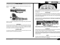
Masterflow
DC2476
DIGITAL MASTERING PROCESSOR
COPYRIGHT
This manual is copyrighted 8 2001 by Drawmer Electronics, Ltd. With all rights reserved. Under copyright laws, no part of this publication
may be reproduced, transmitted, stored in a retrieval system or translated into any language in any form by any means, mechanical, optical, electronic, recording, or otherwise, without the written permission of Drawmer Electronics Ltd
ONE YEAR LIMITED WARRANTY
Drawmer Electronics Ltd., warrants the Drawmer DC2476 Digital audio processor to conform substantially to the specifications of this manual for a period of one year from the original
date of purchase when used in accordance with the specifications detailed in this manual. In the case of a valid warranty
claim, your sole and exclusive remedy and Drawmer’s entire liability under any theory of liability will be to, at Drawmer=s discretion, repair or replace the product without charge, or, if not possible, to refund the purchase price to you. This warranty is not transferable. It applies only to the original purchaser of the product.
For warranty service please call your local Drawmer dealer.
Alternatively call Drawmer Electronics Ltd. at +44 (0)1709
527574. Then ship the defective product, with transportation
and insurance charges pre-paid, to Drawmer Electronics Ltd.,
Coleman Street, Parkgate, Rotherham, S62 6EL UK. Write the
RA number in large letters in a prominent position on the shipping box. Enclose your name, address, telephone number, copy
of the original sales invoice and a detailed description of the
problem. Drawmer will not accept responsibility for loss or damage during transit.
This warranty is void if the product has been damaged by misuse, modification or unauthorised repair.
THIS WARRANTY IS IN LIEU OF ALL WARRANTIES,
WHETHER ORAL OR WRITTEN, EXPRESSED, IMPLIED OR
STATUTORY. DRAWMER MAKES NO OTHER WARRANTY
EITHER EXPRESS OR IMPLIED, INCLUDING, WITHOUT
LIMITATION, ANY IMPLIED WARRANTIES OF
MERCHANTABILITY, FITNESS FOR A PARTICULAR PURPOSE, OR NON-INFRINGEMENT. PURCHASER’S SOLE AND
EXCLUSIVE REMEDY UNDER THIS WARRANTY SHALL BE
REPAIR OR REPLACEMENT AS SPECIFIED HEREIN.
IN NO EVENT WILL DRAWMER ELECTRONICS LTD. BE LIABLE FOR ANY DIRECT, INDIRECT, SPECIAL, INCIDENTAL
OR CONSEQUENTIAL DAMAGES RESULTING FROM ANY
DEFECT IN THE PRODUCT, INCLUDING LOST PROFITS,
DAMAGE TO PROPERTY, AND, TO THE EXTENT PERMITTED BY LAW, DAMAGE FOR PERSONAL INJURY, EVEN IF
DRAWMER HAS BEEN ADVISED OF THE POSSIBILITY OF
SUCH DAMAGES.
Some states and specific countries do not allow the exclusion
of implied warranties or limitations on how long an implied warranty may last, so the above limitations may not apply to you.
This warranty gives you specific legal rights. You may have
additional rights that vary from state to state, and country to
country.
In the interests of product development, Drawmer reserve the right to modify or improve specifications of
this product at any time, without prior notice.
2
CONTENTS
Warranty . . . . . . . . . . . . . . . . . . . . . . . . . . . . . . . . . . . . . . . 2
Contents . . . . . . . . . . . . . . . . . . . . . . . . . . . . . . . . . . . . . . . 3
Safety Consideration . . . . . . . . . . . . . . . . . . . . . . . . . . . . . 4
Radio Frequencies Statement . . . . . . . . . . . . . . . . . . . . . . 4
Chapter 1 - DC2476 Digital Mastering Processor
Introduction . . . . . . . . . . . . . . . . . . . . . . . . . . . . . . . . . . . . 5
Audio Connections . . . . . . . . . . . . . . . . . . . . . . . . . . . . . . . 6
Installation Precautions. . . . . . . . . . . . . . . . . . . . . . . . . . . . 6
Installation and Connection Guide . . . . . . . . . . . . . . . . . . . . 7
Getting Started . . . . . . . . . . . . . . . . . . . . . . . . . . . . . . . . . 8
Chapter 2 - DC2476 Navigation
Finding your way around. . . . . . . . . . . . . . . . . . . . . . . . . . . 9
Effects Screen Navigation Map . . .. . . . . . . . . . . . . . . . . . 10
Chapter 3 - Control Key Overview
Patch . . . . . . . . . . . . . . . . . . . . . . . . . . . . . . . . . . . . . . . . 12
Global . . . . . . . . . . . . . . . . . . . . . . . . . . . . . . . . . . . . . . . 16
Control Keys . . . . . . . . . . . . . . . . . . . . . . . . . . . . . . . . . . 20
LED Display . . . . . . . . . . . . . . . . . . . . . . . . . . . . . . . . . . 20
Chain/ Param . . . . . . . . . . . . . . . . . . . . . . . . . . . . . . . . . . 21
Effects . . . . . . . . . . . . . . . . . . . . . . . . . . . . . . . . . . . . . . . . 21
Bypass . . . . . . . . . . . . . . . . . . . . . . . . . . . . . . . . . . . . . . . 21
Compare . . . . . . . . . . . . . . . . . . . . . . . . . . . . . . . . . . . . . 21
FX Bypass . . . . . . . . . . . . . . . . . . . . . . . . . . . . . . . . . . . . 21
FX Solo . . . . . . . . . . . . . . . . . . . . . . . . . . . . . . . . . . . . . . 21
Help . . . . . . . . . . . . . . . . . . . . . . . . . . . . . . . . . . . . . . . . . 21
Chapter 4 - Basic Effects
Introduction . . . . . . . . . . . . . . . . . . . . . . . . . . . . . . . . . . . . 22
Input . . . . . . . . . . . . . . . . . . . . . . . . . . . . . . . . . . . . . . . . . 25
Dynamic Equaliser and Full Band Compressor . . . . . . . . . 26
Equaliser . . . . . . . . . . . . . . . . . . . . . . . . . . . . . . . . . . . . . . 27
Expander . . . . . . . . . . . . . . . . . . . . . . . . . . . . . . . . . . . . . . 28
Bootstrap Compressor . . . . . . . . . . . . . . . . . . . . . . . . . . . 28
Limiter and Stereo Image . . . . . . . . . . . . . . . . . . . . . . . . . 29
3 Band Tube Saturation . . . . . . . . . . . . . . . . . . . . . . . . . . 29
Output . . . . . . . . . . . . . . . . . . . . . . . . . . . . . . . . . . . . . . . . 30
Cross-Over . . . . . . . . . . . . . . . . . . . . . . . . . . . . . . . . . . . . 31
Compare . . . . . . . . . . . . . . . . . . . . . . . . . . . . . . . . . . . . 31
Chapter 5 - Operation . . . . . . . . . . . . . . . . . . . . . . . . . . . . 32
Chapter 6 - Information
Preset Factory Patches . . . . . . . . . . . . . . . . . . . . . . . . . . . 34
Midi Control Codes . . . . . . . . . . . . . . . . . . . . . . . . . . . 36
Chapter 7 - General Information
If a fault develops . . . . . . . . . . . . . . . . . . . . . . . . . . . . . . . 37
Contacting Drawmer . . . . . . . . . . . . . . . . . . . . . . . . . . . . . 37
Chapter 8 - DC2476 Data
Specification . . . . . . . . . . . . . . . . . . . . . . . . . . . . . . . . . . . 38
Block Diagrams . . . . . . . . . . . . . . . . . . . . . . . . . . . . . . . . . 39
3
DRAWMER DC2476
For the USA
DIGITAL MASTERING PROCESSOR
FEDERAL COMMUNICATIONS COMMISSION RADIO FREQUENCY INTERFERENCE STATEMENT
This equipment has been tested and found to comply with the limits for a
Class B digital device, pursuant to Part 15 of the FCC Rules. These limits
are designed to provide reasonable protection against harmful interference
in a residential installation. This equipment generates, uses and can radiate
radio frequency energy and, if not installed and used in accordance with the
instructions, may cause harmful interference to radio communications. However, there is no guarantee that interference will not occur in a particular
installation. If this equipment does cause interference to radio or television
reception, which can be determined by turning the equipment off an on, then
the user is encouraged to try to correct the interference by one or more of
the following measures:
Re-orient or relocate the receiving antenna.
Increase the separation between the equipment and the receiver.
Connect the equipment into an outlet on a circuit different from that
to which the receiver is connected.
Consult the dealer or an experienced radio/TV technician for help.
SAFETY CONSIDERATIONS
CAUTION - MAINS FUSE
TO REDUCE THE RISK OF FIRE REPLACE THE MAINS FUSE
ONLY WITH A FUSE THAT CONFORMS TO IEC 127-2.
250 VOLT WORKING, TIME DELAY TYPE AND BODY
SIZE OF 20mm x 5mm.
THE MAINS INPUT FUSE MUST BE RATED AT T500mA.
CAUTION - MAINS CABLE
DO NOT ATTEMPT TO CHANGE OR TAMPER WITH THE SUPPLIED MAINS CABLE.
DO NOT PERFORM ANY SERVICING. REFER ALL SERVICING
TO QUALIFIED SERVICE PERSONNEL.
Unauthorised changes or modification to this system can void the users=
authority to operate this equipment.
This equipment requires shielded interface cables in order to meet FCC
class B limit.
WARNING
For Canada
CAUTION - SERVICING
TO REDUCE THE RISK OF FIRE OR ELECTRIC SHOCK DO
NOT EXPOSE THIS EQUIPMENT TO RAIN OR MOISTURE.
CLASS B
NOTICE
This digital apparatus does not exceed the Class B limits for radio noise
emissions set out in the Radio Interference Regulations of the Canadian
Department of Communications.
CLASSE B
AVIS
Cet appareil numérique ne dépasse pas les limites de la classe B au niveau
des émissions de bruits radioélectriques fixés dans le Règlement des signaux
parasites par le ministère Canadien des Communications.
4
CHAPTER 1
DRAWMER DC2476 DIGITAL
MASTERING PROCESSOR
INTRODUCTION
The Drawmer DC2476 is an extremely sophisticated, all-digital stereo
mastering processor designed for use in demanding recording and
broadcast applications. Both analogue (balanced XLR) and digital (AES/
EBU and S/PDIF) I/O is provided as standard. The audio converters are
24-bit and the digital output can be either 16, 18, 20 or 24-bit at sample
rates of up to 96kHz. Noise shaped dithering is included and Word Clock
input and output is available. A new feature is Output Trim which sets the
maximum level that output can reach, even in bypass, making the DC2476
easier to use in a broadcast environment.
Designed to be extremely easy and intuitive to use, the Drawmer DC2476
comprises a stage of dynamic equalisation, also incorporating full-band
compression (the DQ stage), followed by a five-band equaliser modelled on
the response of classic analogue filters. The signal is then split into three
user definable bands where it is routed via a three-band expander, a threeband compressor, a three-band limiter and a three-band modelled tube
saturation stage. The three bands are then recombined before being fed to
the output stage via a fader system that can be used to generate precise
fade-ins and fade-outs of user definable length. The output stage itself offers
a number of dither options.
This makes setting up far more intuitive when adjusting the individual bands
of a multi-band compressor and also avoids the necessity to juggle the
make-up gain control settings.
Why 96kHz?
Digital processing has until now been confined to 48kHz sampling frequency.
In order to achieve the required bandwidth for professional audio, a very
severe low pass filter at 23kHz is required to separate analogue signal
frequencies from the clock frequency otherwise unpleasant aliasing will occur.
This requires the use of a FIR digital filter which is part of the A/D and D/A
converters. Unfortunately these filters cause what is known as >time smear=,
where short transients are smeared over a longer time period giving loss of
HF detail. At 96kHz sample frequency, the low pass filter is less severe and
at twice the frequency, so time smear is considerably reduced.
A second important consideration is the increased audio bandwidth up to
40kHz. This allows harmonics which extend above human hearing to be
generated and preserved. These harmonics, although not audible
themselves, make a contribution to the sound quality.
Finally, the user interface has been designed to make the Drawmer DC2476
as simple to operate as possible. In fact, once you’ve got used to using the
cursor buttons, the Adjust knob and the Adjust knob push switch to move
around the various screens and their parameters, operation is almost entirely
intuitive. Custom graphics are used wherever possible to monitor the
processor function and its adjustments while front panel LED bargraph meters
constantly monitor the input and output signal levels, limiter activity, plus the
amount of gain reduction being applied in each of the three frequency bands.
Although a wide range of manual control is provided, an automated gain
management system is used in addition to 'Programme Adaptive' time
constant management in the compressor and expander stages. The
automatic gain management monitors the signal level at critical points
throughout the signal chain and automatically reduces levels in situations
when overloads would otherwise occur. This makes the Drawmer DC2476
impossible to overload. Another key feature is the use of a 'Bootstrap'
compressor. Conventional compressors reduce the level of audio peaks, which
means make-up gain has to be applied to restore the same peak level. The
Drawmer DC2476 works the other way around by instead increasing the level
of quieter signals and leaving the peak levels at their original values.
5
AUDIO CONNECTIONS
INSTALLATION PRECAUTIONS
Analogue Inputs
The inputs and outputs to the DC2476 are electronically balanced and would
normally be connected to your system via a patchbay. Should unbalanced
operation be required, simply ground pin 3 on the XLR connectors.
If earth loop hum problems are encountered, do not disconnect the mains
earth but instead, try disconnecting one end of the signal screen on the
cables connecting the DC2476 to the patchbay. If such measures are
necessary, balanced operation is recommended.
Should a fuse blow, replace it only with the same type and value as the one
fitted.
AES/EBU
Is via an XLR connector designed to be used with standard balanced
microphone cable (20 metres maximum), wired pin 1 screen, pin 2 and 3
balanced data, and the XLR shell connected to the chassis. Having many
short cables joined together is not advisable as each connector can cause
undesirable signal reflections.
The output socket fully conforms to the EMC standards; if the unit is to be
used where it may be exposed to high levels of disturbance, such as found
close to a TV or radio transmitter, it is suggested that the screen of the data
cable be connected to the chassis connection on the XLR type connector
rather than to pin 1.
If ground loop problems are encountered, never disconnect the mains ground,
but instead, try disconnecting the signal screen on one end of each cable
connecting the outputs.
S/PDIF
Is via a high quality RCA type phono jack where the data conforms to the
SonyJ PhillipsJ Digital InterFace format. Because this connector only
provides an unbalanced termination, the recommended maximum length
for this cable is 3 metres, even with very high quality cable.
Word Clock
For external clock synchronisation or when the DC2476 is providing the
clock to another source, this is carried out via the 50Ω BNC connector.
Midi
When wiring to another piece of equipment via the Midi sockets it is necessary
to use a Standard 3-Wire Midi cable and not the five wire Midiplus type.
6
When installing the DC2476, ensure that it is allowed sufficient ventilation
and avoid mounting it next to excessively hot pieces of equipment or devices
emitting a strong magnetic field such as is often the case with power
amplifiers. If the unit is to be used in a mobile situation, it is strongly
recommended that the rear of the unit is supported in the carrying rack to
avoid bending the front panel rack mounting ‘ears’.
Should the unit require cleaning, use a damp cloth with a little liquid detergent;
do not use thinners or spirit cleaners as these may attack the finish.
INSTALLATION AND CONNECTION GUIDE
7
GETTING STARTED
Analogue input.
Connect Left and Right input signals via the analogue XLR sockets. The
rear panel push switch selects between maximum input levels of +7dBu
and +21dBu. This is the level at which the internal analogue electronics will
clip, causing distortion, and corresponds to normal -10 and +4dB operating
levels.
The best noise performance is obtained when the peaks of the input signal
are just below the selected maximum level. This can be viewed on the input
signal meters.
Avoid signal peaks lighting the RED LEDs, since this indicates possible
clipping.
The input page allows up to 18dB digital gain to be applied to lower level
input signals (see Basic Effects).
Navigation.
We recommend that you take a little time to look at the navigation diagram
and screen descriptions so that you are aware of what everything means,
although in most cases this will be obvious.
Also take a look at the block diagram which describes the signal path.
Quick Start.
The easiest way to get started is to select one of the 50 factory patches.
To do this, press PATCH, then go to LOAD using the Left/Right scroll buttons.
Select “READY TO LOAD” then turn the knob to select a patch, then push
the knob to load the patch.
All internal controls will slide to their new values almost instantly, allowing
instant comparisons to be made.
8
Basic Guide.
Although it is not possible to drive the DC2476 into clipping (because of the
automatic gain management system), it is still possible to produce a subjectively bad sound by grossly overprocessing the signal. The individual processor blocks all provide a very wide range of control as you may, on occasion, need to use only one block to achieve a specific result. However, if
several blocks are combined where a high level of processing is taking place
in each one, the end result is likely to be seriously overprocessed.
For example, using large amounts of compression followed by high levels of
Tube Drive can sound excessive. It’s also worth noting that the equaliser
behaves more like an analogue equaliser than some other digital EQs you
may have tried. It’s not uncommon for digital equalisers to require very large
amounts of cut or boost to achieve the desired subjective result, but with the
DC2476, you’ll find that even very subtle changes of EQ level have an audible effect, just as in the best analogue equalisers.
CHAPTER 2
DC2476 NAVIGATION
FINDING YOUR WAY AROUND
Despite its high degree of sophistication, the DC2476 has been provided
with a friendly and intuitive operating system which uses the same navigation
method for all the effect screens.
To make the effect screens easier to follow and because there are so many
parameters attributed to all the different Effects, these have been arranged
so that, where possible, they represent the layout of an equivalent analogue
device.
Once the appropriate Patch, Effects or Global sections have been selected,
navigation is accomplished by using the four arrowed cursor keys, the Adjust
knob (which includes an integral push switch) and the Chain/Parameter
button. In Chain mode, the Left/Right cursor buttons are used to select the
effect block to be edited, after which the button may be pressed again to
toggle into Parameter mode. Where an effects block has more than one
screen, the Up/Down cursors are used to scroll around them. A ‘C’ or ‘P’
icon in the top left corner of the display window indicates whether the unit is
currently in Chain or Parameter mode.
In order to reduce the number of key presses required, all the features are
designed to work using a scroll around method.
Therefore, to step from Page 1 to Page 3 and from Page 3 to Page 1 only
one key press is required.
(Up or Down Cursor)
Similarly, to move from the far left hand side to the far right hand side or
reverse on the Chain or Param feature only one key press is required.
(Left or Right Cursor)
The example demonstrates how straight forward the operating system
has been designed to work.
To adjust the Mid band in the Attack of the Expander page.
Step 1.
From the Input page, press the Chain/Param button to ensure that the
Chain icon
is visible.
Step 2.
Press the Right arrow
Expander page.
on the Rocker until it has moved across to the
Step 3.
Now press the Chain/Param button to ensure that the Param icon
visible.
is
Press the left
or right
rocker on the unit to move around the
parameters within the screen. i.e. THR, RAT etc.
Move across to ATTACK (ATT)
Step 4.
Press the control knob to toggle between the different parameters on the left
hand side of the screen. (In this case Full, Low, Mid and High).
Press the control knob until the Mid function is highlighted.
Rotate the control knob to either decrease or increase the level to the required
value.
A common operation sequence is used to select and change parameters
within the DC2476 which is both straightforward and intuitive:
Step 1.
Step 2.
Step 3.
Step 4.
9
SCREEN NAVIGATION MAP
The Effects Screens
The Global Screens
10
11
CHAPTER 3
CONTROL KEY OVERVIEW.
PATCH MENU
SOURCE
This section enables the user to select the internal RAM, the optional S-RAM
card or the Factory patches. In addition, effect blocks may be loaded from
existing patches and copied into the patch being edited. As delivered, the
unit contains 50 preset factory patches that cannot be overwritten as well as
128 memory locations into which user patches may be stored for later use. If
the S-RAM card is fitted, a further 128 patches may be stored.
LOAD FROM INTERNAL MEMORY
Enables patches to be loaded from the selected factory or user memory.
To load a patch, proceed as follows:
Press Patch to enter the Patch load/save window. With the Chain/Param button
set to Chain (C), use the left/right cursor buttons to select Load from RAM or
Load from Card. The options are displayed along the top of the screen.
If the desired bank of patches is being displayed (ie User or Factory), and
Source is selected in the bottom row, use the Adjust knob to select the patch
for loading, then press the Adjust knob to load the chosen patch. As the patch
is loaded, the parameter settings within the various blocks are ‘morphed’ to
their new values so there are no gaps or glitches, even when patches are
changed while audio is playing.
To change from User to Factory bank, press Chain/Param so that ‘P’ is showing
in the top left hand corner of the display, then press the Adjust knob to toggle
between the Factory and user banks.
In this mode, it is also possible to select between Source, Block and Ready to
Load on the bottom row of the display, again using the Left right cursor buttons.
When Block is selected, an underscore appears beneath one of the blocks in
the signal chain block diagram. Pressing the Adjust knob loads this block from
the selected patch and loads it into the patch currently running.
12
SAVE
Enables newly created patches to be saved to either the user memories or
to the optional S-RAM card. Newly created patches may be named with up
to 16 letters.
To save the patch currently running on the machine, select ‘Save to RAM’ or
‘Save to Card” as required using the Left/Right cursor keys (C mode). Next,
select the patch location in which the current patch will be saved using the
left/right cursor buttons (P mode).
Before saving the patch, it should be named by advancing the cursor to
Text. Here the Adjust knob is used to scroll through the character set while
pressing Adjust enters the currently selected letter and moves onto the next
position. If a mistake is made, selecting Cursor Position enables the cursor
to be moved back to previously entered characters.
Once the patch has been named, advancing the cursor to Ready to Save
and pressing Adjust completes the process. During saving, a warning
message is shown reminding the user not to switch off the power until saving
is complete. Note that saving over an existing patch takes a little longer as a
certain amount of software housekeeping takes place.
Loading and saving data to the optional card follows the same procedure,
except that the card is selected as the patch source or destination. The card
must not be write protected if patch saving is required.
PATCH - LOAD FROM INTERNAL MEMORY
Shows the selected page function.
Show a selection of patches.
Rotate the control knob to scroll
through a selection of patches.
Push to load.
Shows the currently loaded patch.
“F:” shows the source of the last
patch loaded:
C = Card ; F = Factory ; U = User
Arrow marks currently loaded patch.
Allows a particular block from a
patch to be loaded.
Allows the user to select either
Factory or User Patches.
Press the knob to toggle between
Fact and User.
See page 34 for Factory Preset
names and descriptions
PATCH - SAVE TO INTERNAL MEMORY
Shows the selected page function.
Allows the user to scroll through
the patch names.
Allows the Patch name to be
inserted.
Rotate the knob to select a letter
from the keypad - push to select.
Press to save the Patch.
Allows the name to be edited.
13
PATCH - TOOLS
Shows the selected page function.
When “Off” is highlighted press knob
to toggle between OFF/ON.
When Pv is selected (using the
Chain/Param button).
Use the
Left or Right button
to move
between “MEMORY
PROTECTED”, “OFF/ON”
“FORMAT CARD” and “READY”.
14
“Write Protect: ON” is also displayed
on the “save to card” page.
When “READY” is highlighted press
knob to format the card.
PATCH - LOAD FROM CARD
Shows the selected page function.
Show a selection of patches.
Shows the card status.
Shows the currently loaded patch.
“C:” shows the source of the last
patch:
C = Card ; F = Factory ; U = User
Arrow shows currently selected
patch.
Shows the selected patch.
Rotate the control knob to scroll
through a selection of patches.
Push to load.
Allows a particular block from a
patch to be loaded.
i.e load EQ and Tube Drive only.
PATCH - SAVE TO CARD
Shows the selected page function.
Lets the user scroll through the
patch names.
Press to save the Patch when selected
Allows the name to be edited.
Allows the Patch name to be inserted.
Text is selected form the Character
Set.
Use knob to select cursor position,
then go back to text to select new
letter.
15
GLOBAL MENU
The Global menu has six sections: Dig I/O, External Clock (XCLK), Word
Length and Dither (OUT), Misc, Midi and Sine wave generator (SINE).
DIG I/O
Dig I/O enables the user to select either the analogue or digital input (both
analogue and digital outputs are always active) and the digital input format
(AES/EBU or S/PDIF with or without external wordclock sync). Ext sync
options should only be selected whenever a wordclock input is present. If
Ext is not selected, the system synchronises to the clock subcode of the
incoming data stream.
The left hand side of the screen allows the input analogue sample rate to be
set between 32kHz and 96kHz, though there’s also an external mode for
use with external word clock sources. The analogue input is always sampled
at 24-bits to maintain maximum digital headroom and resolution throughout
the processing chain.
Note:
If a digital input has been selected but no
digital devise is connected to the unit then
the sample rate leds will flash (see diagram) .
The right hand side of the screen allows
the output sample rate to be set between
32kHz and 96kH
XCLK.
This page allows the External Clock on the rear of the unit to be set to either
the input or output sample rate as set on the DIGIO page.
16
OUT - Dither and Noise Shaping
Where necessary, noise shaped dither can be applied to reduce the bit depth
while maintaining the maximum possible dynamic range. It allows the output
bit-depth to be set (24, 20, 18 or 16-bit) and the output dither strength and
shape to be chosen. The four Shape windows signify the area of the spectrum
into which dither noise is shifted while the boxes to the left enable the dither
level to be set to High, Medium, Low or Off. The best dither option is generally
best arrived at by critical listening, though a suggested starting point is Medium
level and a Gentle Slope. ( White Noise Dither).
Only white noise dither is available at 88.2kHz and 96kHz sample rates.
Position Dither and Noise Shaping
1
2
3
4
White Noise dither applied to the signal
12Khz of Dither applied to the signal
15Khz of Dither applied to the signal
22Khz of Dither applied to the signal
MISC
The Miscellaneous page provides access to the screen contrast to allow for
a wide range of viewing angles.
MIDI
Patch changes can be made via “MIDI”, see page 17, to select midi channel
and patch source.
SINE
New to the DC2476 is the sine wave generator, used as an aid when calibrating
your recording studio equipment.
GLOBAL - DIGIO
When Pv is selected (using the
Chain/Param button).
Use the
Left or Right button
to select
either the Analogue In
SRate, Digital In/Clk or the Output
SRate.
When the Output SRate is being
adjusted the previous value is shown
in a black box and the selected value
is in a clear box. When the new value
has been selected, the old value is
cleared and the new box is blackened.
Rotate the control knob to the
required input signal. Push the
control knob to select the function.
The selected sample rate is shown
on the screen in a blackened box.
When the OP sample rate is set to
<AS I/P> (as input) the digital output
will be at the same rate as the input
sample rate or if an EXT is selected
and a wordclock source is connected
to the wordclock input BNC, the digital outputs will be at this external
word clock sample rate.
If a digital input has been selected
but no digital devise is connected then
the sample rate leds flash.
Displays the clock frequency for either
digital or analogue.
GLOBAL - EXTERNAL CLOCK
This page allows the External Clock
on the rear of the unit to be set to
either the input or output sample rates
as set on the DIGIO page.
Push the knob to select either the
input or output sample rate.
17
GLOBAL - OUT
OP Trim is the very last procedure in
the effect chain.
Rotate the knob to enter the selection.
! Note:
The OP TRIM sets an output level
which the DC2476 will never rise
above.
This also occurs when the unit is in
bypass mode - so as not to damage
sensitive equipment.
The “MED” shape is the preferred
setting for general purpose.
Push the knob to select either Dither
Level, Shape , Word Length or OP
Trim..
White Noise Dither is shown here.
GLOBAL - MISC
When Pv is selected (using the
Chain/Param button).
Rotate the knob to adjust
the display contrast to
suit ambient lighting.
18
GLOBAL - MIDI
When Pv is selected (using the
Chain/Param button).
Use the
Left or Right button
to select either the MIDI RX CHAN
or the PROG CHANGE LOADS.
When selected push knob to toggle
Programme Change on/off.
When selected push knob to toggle
Continuous Control on/off.
When the MIDI RX is selected.
Turning the knob changes the MIDI
Receive channel 1 - 16 enabling
Patch changes to be made via a
MIDI device.
Enables patches to be loaded from:
Factory Presets,
User Presets,
Card Presets,
when a midi programme change is
sent.
GLOBAL - SINE
A 1kHz tone is generated at the level
set.
Rotate the knob and push to activate
at the desired level.
The sine wave generator is only active when on this page.
19
CONTROL KEYS
LED DISPLAY
The main controls keys are:
The
UP key and the
DOWN keys which
are used to scroll up or down through the display pages.
The
LEFT key and the
RIGHT key which are
used to move along either the CHAIN or the PARAMETER function,
depending on which has been selected by the Chain/Param button.
Edited Patch
This is highlighted when the loaded Patch (User or Factory) has been
edited.
Midi Active
This will display only when the midi interface is in use.
The Control knob is a dual purpose device which is used as a band selector
and also to adjust the parameter values.
The control knob is set so that the Band that needs adjusting is selected by
PUSHING the control knob to the required band. The value is set by
ROTATING the rotary control knob to the required value.
Fade
The Fade will indicate that a Fade Up or a Fade Down is in progress. This
is set on the Output Page.
EXT. Clock
This shows that the DC2476 is being controlled from an External Clock
Source.
The External Sample Rate can be monitored by selecting the Misc page on
Global.
High Rate
When this LED is highlighted the Sample Rate is either 96.0K or 88.2K.
Low Rate
Indicates that the Sample Rate is 48.0K, 44.1K or 32.0K.
20
CHAIN / PARAM
This switch allows the user to select the required movement of the cursor.
With the ACHAIN@ highlighted the cursor manoeuvres through the chain of
effects.
COMPARE
When changes are made to a selected patch, press to Compare the original
settings with the new ones. Press again to return to the previous screen.
See page 30.
FX BYPASS
Allows individual effects blocks to be bypassed. This enables the contribution
of individual blocks or combinations of blocks to be checked, making editing
much easier. When the FX Bypass LED is illuminated, the currently selected
effects block is bypassed.
Parameters that are currently bypassed are highlighted on the parameter
chain by having no line at the base of their icon. e.g. Here the equaliser and
tube drive are bypassed.
When the APARAM@ is highlighted the cursor toggles along the parameters
within the screen.
EFFECTS
This is the mode used to access and adjust the individual effects blocks in
the signal chain. A brief description of how the effects page are navigated
can be found in Chapter 2 Finding Your Way Around. A detailed description
of the Effects can be found in Chapter 4 Basic Effects.
BYPASS UNIT
This allows the signal to Bypass the DC2476 so that the signal can pass
directly through the unit without being affected.
Bypass status is saved to a patch: in order to reload bypass status <ALL>
must be selected on the “Block Load” section of the load patch page.
FX SOLO
Allows all effects blocks other than the one currently selected to be bypassed
so that the effect of that block can be evaluated in isolation.
Although the SOLO status of a block is not saved to a user patch, the same
result can be achieved by bypassing all blocks other than the one required in
the processing chain. Reload using <ALL> in the “Block Load” section of the
load patch page.
HELP
Provides context sensitive help relating to the current selection. The Help
page will remain until the button is released.
21
CHAPTER 4
BASIC EFFECTS
The signal chain comprises six blocks in addition to the Input and Output
sections, which are addressed in exactly the same way as the effects blocks.
The DQ and Equaliser blocks are of necessity full-band (they affect the
entire signal), while the Expander, Compressor, Limiter and Tube Drive
sections that follow are all three-band. Three-band processing enables more
processing to be applied without introducing unwanted side effects, and
also allows for creative processing that alters the overall spectral balance of
the signal.
INPUT PAGE
The input page shows the signals as a graphic display of the signal level
passing to the effects functions. A dotted line at the top of each display
shows the maximum signal level. Use the control knob to adjust input levels.
Push the knob to select Left/Right/Both, then turn to adjust.
The internal >gain management= will reduce gain if signal peaks are too
high and would otherwise cause distortion. This is shown on the input screen
GR meter (see diagram). Adjust gain so that the GR meter shows minimum
activity, responding only to the signal highest peaks.
DYNAMIC EQ AND FULL BAND COMPRESSOR
A high performance floating threshold dynamic equaliser consists of a single
band parametric EQ with up to 12dB Boost or Cut, under dynamic control.
Frequency is adjustable from 64Hz to 8kHz in semitone increments with
bandwidths from 0.25 to 3 octave. This is shown graphically on the LCD
screen as a familiar EQ curve. Dynamic gain (DGAIN) is variable from -12dB
to +12dB. Positive values produce enhancement of the selected frequency
band, whilst negative values produce a reduction. Negative values may be
used for frequency-selective de-essing or de-popping while positive values
‘expand’ the selected frequency range, making it more prominent.
22
Because the process is dynamic, low level signals will not be treated, and
when enhancing low frequencies to add punch to a mix, this can help avoid
muddying the mid range while keeping the bass sound tighter than trying to
do the same thing with conventional EQ. Selecting ‘Filter’ puts the DC2476
into filter listen mode so that filter characteristics may easily be evaluated.
Pushing the knob when adjusting Frequency or Bandwidth selects output as
Normal or Filter. Selecting Filter enables the filtered signal to be monitored
without processing. This helps in locating the exact frequency to be processed
by the Dynamic EQ and is of particular value when using negative DGAIN
values.Normal is auto selected when other parameters are selected or when
leaving the Dynamic EQ block.
Though the DC2476 includes a three-band compressor, it can sometimes
be useful to apply a degree of compression prior to equalisation. For this
reason, the DQ section also includes a full-band compressor. Like the later
three-band compressor, this has a bootstrap characteristic where the level
of low level signals is increased rather than high level signals being
decreased. The position of the dotted line across the display window shows
by how much low level signals have been increased.
The compressor section has three controls. COMP adjusts the amount of
compression and has a range from -24dB to +24dB. Positive values compress
the full band signal whilst negative values are used to de-compress or expand
material which is already over compressed. Attack and Release controls are
semi-automatic, programme adaptive, providing a wide range of user control
and at the same time taking account of the dynamics of the signal. The
dotted line across the graphic display indicates the amount of compression
(i.e. the amount of gain applied at low levels). A GR bar display to the right of
the screen and connected to the dotted line indicates gain reduction. This
shows the gain being reduced back to 0dB in response to high level signals.
Conversely, when COMP is set to a negative value, the dotted line shows
the attenuation applied to low level signals, with the bar meter showing rises
in gain towards 0dB as the signal increases in level. Positive Dynamic EQ
(DGAIN) and Compressor (COMP) settings can produce signals which could
cause overload. The Gain Management will reduce the signal level when
this occurs. This is shown on the on screen GR meter and is also affected
by any boost applied by the EQ section.
See EQ GAIN MANAGEMENT below.
EQUALISER
3 BAND EXPANDER/GATE
The equaliser section consists of an analogue modelled 5 band parametric
equaliser with a wide range of frequency and bandwidth. Up to 18dB boost
or Cut is available on each band. Bass and Treble bands have selectable
Shelf or Bell(Peaking) filter shapes whereas the 3 mid bands are bell only.
All bell filters have a frequency range from 32Hz to 22kHz in 1 semitone
steps. Bandwidth range is from 0.08 octave (1 semitone) to 5 Octaves.
Expanders are generally used to remove unwanted noise during what should
be passages of silence, but are also a means of >undoing= gain at very low
levels due to compression, where the noise floor is pulled up to an
unacceptably high level. Threshold, Ratio, Attack, Release and Range
adjustments allow a wide range of control, with Program Adaptive techniques
used to make real time adjustments depending on the nature of the signal.
The graphical display shows a plot of the selected frequency curve. When
each band is selected, a small vertical bar appears across the 0dB line on
the graph. This indicates the centre frequency of the selected band, which is
useful in locating the position of each band, either before Cut or Boost is
applied, or when a complex EQ curve is in use.
The incoming signal levels of each band are displayed in the Threshold box,
rising from !96dB towards 0dB. Rotating the knob clockwise takes the wider
threshold bars down towards the signal. As the signal approaches threshold,
the gate begins to open at the Attack rate until, as the two bars touch, the
gate will fully open. This gives a clear indication at all times of where the
signal is in relation to the threshold. As the signal level drops below the
threshold bar, the expander begins to reduce gain by an amount dependent
on the Ratio setting and at the Release rate. The onset of expansion causes
the appropriate expander LED under the main output VU meters to illuminate.
The Range control is used to limit the maximum amount of expansion,
regardless of Ratio settings. This can be used to prevent excessive expander
activity and improve transparency.
EQ GAIN MANAGEMENT
Since both the Dynamic EQ, Compressor and Parametric Equalisers are
capable of increasing overall gain, the GAIN MANAGEMENT treats them
as a single set of functions, since gain applied in the dynamic EQ or
Compressor can be reduced again in the main EQ. Once both EQ=s have
been adjusted for best results, use Gain Trim on either DQ or EQ pages to
reduce gain to keep Gain Reduction to a minimum.
If the gain is not trimmed to keep gain reduction to a minimum, the signal
will, in effect be limited, which can alter the subjective nature of the sound
being processed.
THREE BAND PROCESSING
3 BAND BOOTSTRAP COMPRESSOR
The purpose of the Bootstrap Compressor is to pull signals up towards digital
full scale. This combined with Program Adaptive algorithms provides punch,
enhances spectral detail and delivers well controlled power. Threshold, Ratio,
Attack, Release and Gain adjustments are available. Simply increase
Threshold and Ratio.
The main purpose of the split band section is to allow the three different
parts of the audio spectrum to be treated independently so as to minimise
side effects, but each of the dynamic processes may be adjusted differently
in each of the three bands if required. This opens up many creative
possibilities for introducing level dependent spectral changes.
The user may adjust the two crossover points that define the three frequency
bands into which the signal is split prior to processing. The crossover
frequencies may be accessed from the second page of any of the split-band
effects blocks.
23
LIMITER AND STEREO IMAGE
OUTPUT
The three-band limiter is designed to allow peaks signal levels to be controlled
without introducing audible side effects unless the amount of limiting is
considerable. This may be used to maximize the subjective level of recordings
being mastered without affecting the overall sound or peak level, but it is
also possible to adjust the release time of individual bands to provide the
most transparent results. The limiting threshold is preset to digital full scale
so that limiting only occurs when the signal level is such that it would otherwise
have clipped. Spectral changes can be made by balancing the level of the
three frequency bands in the Output section, and as this is still under the
control of the automatic gain management system, it isn’t possible to clip
the output signal.
The Output section provides three level trims for the three frequency bands
prior to summing. Once the signal has been summed it passes through an
auto stereo fader.
The Fade out time may be adjusted from 1 second to 1 minute and a “fade
out” or “fade in” may be initiated by pressing the Adjust knob switch. Pressing
a second time reverses the direction of the fade. The Fade Up time is always
fast and can not be adjusted. When the Output page is left a Fade Up will
occur. As a Fade starts, the FADE LED is illuminated.
The second page of the Output section allows the user to choose from three
different fade curve shapes.
Separate stereo width controls are also provided for the three frequency
bands, enabling the width to either be narrowed to mono or to be widened
further than the original. One major benefit of having independent width
control for each of the bands is to allow the high frequencies to be spread
across a wider soundstage without affecting the low frequency end. Excessive
low frequency widening may lead to phase problems, and in those instances
where a vinyl record is the end result, it may be beneficial to narrow the
stereo image of the bottom band, or even reduce it entirely to mono. This
can reduce cutting problems due to low frequency phase differences.
THREE-BAND TUBE SATURATOR
The tube saturation emulation in the DC2476 is based around an algorithm
that mimics the transfer characteristics of a typical triode tube. This introduces
both level dependent harmonic distortion and compression, making it possible
to recreate the tonal warmth associated with vintage tube equipment.
However, because the Tube Saturation section is spread over three frequency
bands, the enhancement effects of the tube emulation are confined to their
own parts of the frequency spectrum. The outcome is that the signal remains
smooth and musical, even when relatively high amounts of processing are
being applied. Furthermore, because the drive is independently adjustable
in all three bands, it’s possible to use this stage of the DC2476 to achieve
sophisticated spectral reshaping. For example, increasing the tube drive in
the high band creates an effect not unlike a harmonic enhancer, whereas
adding more low band drive adds bass energy and warmth. Control is
extremely simple as the only adjustable parameters are the drive settings of
the three bands.
24
INPUT - Page 1
A Gain Reduction bar display will
appear if the Gain Management has
responded to peaks.
This will occur to peaks that exceeD
-2dBfs.
The dotted line shows the -2dB
ceiling.
Push the control knob to select either
the Left, Right or Both channels for
adjustment.
Adjust either the Left or Right channel
to correct for any stereo image
unbalance.
Signals levels are displayed
over a period of 1-10 Sec.
The Bar graph shows the level of
digital gain that has been applied to
the input signal.
Rotate the control knob to adjust
the speed of the sweep signal.
INPUT - Page 2
...Left signal phase.
When Pv is
selected
(using the
...Left / right swap.
Chain/Param
button).
Use the Left/
Right button ...Right signal phase.
to select....
...Sweep rate of signal
level graphics.
Shows the Input signal with the
revised sweep rate.
Select the rate then rotate the
control knob to adjust the speed of
the sweep signal.
25
DYNAMIC EQUALISER
AND FULL BAND COMPRESSOR
The Gain Reduction bar graph
shows when the Gain Management
has reduced the overall EQ level to
avoid any clipping caused by the
EQ boost.
Shows the amount of compression.
i.e. gain added to low level signals.
Bar graph shows compressor gain
reduction or expander gain.
Push the control knob to select
either Norm or Filter.
Filter is only available when either
FREQ or BW is selected.
When Pv is selected (using the
Chain/Param button).
Use the Left or Right button to step
between Frequency, Bandwidth,
Dgain, Compressor, Attack,
Release, and Gain.
Displays the amount of compression.
Negative values show decompression
i.e. expansion
26
Marker shows the centre frequency
of the selected band.
The Graphical display shows the
signal band for Dynamic EQ.
The Bar meter shows the Gain Trim
level that has been applied. The
Gain Trim level should be set to
keep Gain Reduction to a minimum.
Note:
Trim is shared with the main EQ.
EQUALISER - Page 1
Push the control knob to select
Gain, Frequency or Bandwidth.
The Graphical display shows the
overall EQ Boost/Cut that has been
applied by setting the Gain, Frequency and the Bandwidth..
When Pv is selected. Use the Left
or Right button to step along the
Parameters of each band.
This Marker shows the centre
frequency of the selected band.
This is the Bar meter showing the
Manual Gain Trim level that has
been applied.
The Gain Reduction shows when
the Gain Management has reduced
the EQ level.
EQUALISER - Page 2
The selected filter type will be
shown in the Low and High band
boxes on Page 1.
Turn the knob to select the type of
filter that is required on Lo and Mid
bands.
Push the knob to enter the selection.
27
EXPANDER
When Pv is selected. Use the Left or
Right button
to select either
Threshold, Ratio, Attack, Release or
Range.
Low band
Mid band
This
shows
the band
settings.
High band
Push the control knob to select the
band to be adjusted.
The wider bar shows the threshold
for each band.
When the two bars meet, the gate
is fully open.
Thin bars show signal level for each
band.
BOOTSTRAP COMPRESSOR
When Pv is selected. Use the Left or
Right button
to select either
Threshold, Ratio, Attack, Release or
Range.
Low band
Mid band
Push the control knob to select the
band to be adjusted.
28
High band
This
shows
the band
settings.
LIMITER AND STEREO IMAGE
When Pv is selected. Use the Left or
Right button
to select either
Release or Stereo Image.
The gap indicates possible loss of
mono information as the image is
widened.
Push the control knob to select the
band to be adjusted.
This shows the Low, Mid and High
band values for Stereo Image.
Excess width
Normal width
3 BAND TUBE SATURATION
The highlighted brace shows the
selected tube band.
Push the control knob to select the
band to be adjusted.
Rotate the control knob to adjust
Tube Drive on the selected band.
29
OUTPUT - Page 1
When Pv is selected (using the
Chain/Param button).
Use the Left or Right button to
select either the Level or the Fader
function
Shows whether the fader is up or
down.
Push the control knob to select
which band is to be adjusted.
Push the control knob to start the
Fade Out/ Fade In.
This shows the current fade level.
Shows G.R applied by the Gain
Management after the 3 band signals
have been summed.
Adjust band levels for correct spectral
balance and minimum gain reduction.
OUTPUT - Page 2
Shows the selected fader option.
30
Push the knob to select the required
fader shape.
Cross-over is common to
Expander, Compressor,
Limiter/Width and Tube.
When in “monitor bands” mode pressing the
knob enables you monitor the highlighted band
only.
CROSSOVER
Left/Right
toggles
between
“Moniter
Bands” and
“Set X-Over”.
Push the control knob
to toggle through the
selections.
Rotate the control knob to
adjust to the required value.
On returning to “set x-over” mode you
will still only hear the highlighted band
as set in “monitor bands” mode.
On exiting the x-over
page the full frequency
range is again output.
COMPARE
Press “compare” button to access. Press again to return to previous screen.
Left/Right selects
Normalised Input (with Gain),
Current Settings
Loaded Patch Before Edit.
Turning the knob trims levels for direct
A/B comparison.
Gain applied at Input section
31
CHAPTER 5
OPERATION
It is recommended, where possible, to use a digital input source, though in a
system comprising a mixture of analogue and digital equipment, the high
quality analogue input stage of the DC2476 will yield excellent results.
Balanced operation is recommended to eliminate the possibility of ground
loop induced hum.
In digital systems running from a master word clock, it is generally better to
use the DC2476’s word clock input to provide sync. However, the DC2476 will
also slave to all properly designed S/PDIF and AES/EBU sources providing
proper digital cable is used. The various sync modes can be set up in the I/P
section.
For analogue inputs, set the
rear panel switch to suit the
incoming signal level....
....which should be adjusted so that
the RED LED’s on the input meter
only show signal peaks, if at all.
Though the DC2476 has an automatic gain management system that applies
limiting to signals that would otherwise cause digital ‘clipping’, these limiters
are included primarily as a safety feature. In normal use, the input gain should
be set up (via the I/P page) so that signal peaks come as close to 0dB DFS
as possible without triggering the limiters. The signal levels can be viewed on
the input page using the Level/Time display. Any G.R. caused by the Gain
Management can be seen on the Input screen G.R. meter. Adjust gain for
minimum G.R.
Once the input gain is optimised, the internal signal path has sufficient
headroom to accommodate even quite severe degrees of signal processing,
such as EQ boost. In the event that excessive boost is applied, the automatic
gain management limiters will prevent clipping. However, the signal level must
be reduced at the output of the signal chain in order to fit the bit depth of the
selected output format. If this is not done, the automatic gain management
will limit the signal, and if the degree of limiting is heavy, the audible side
effects may be undesirable. Ideally, the gain management limiters should
operate either only on loud signal peaks, or not at all.
32
The three-band section of the DC2476 includes a stereo width control where
a separate control is provided for each of the three bands. Widening the
bands beyond their default settings increases the stereo spread of the sound
while using a lower setting reduces the stereo width. This feature is particularly
useful when mastering a mix for vinyl release as low frequency phase variations
can make tracking very difficult. Using the DC2476, the stereo width of very
low frequencies can be reduced or even summed to mono without affecting
the mid and high frequency elements of the mix.
The output section includes a sophisticated dithering system for maintaining
maximum dynamic range while reducing the bit depth of a signal. Several
dither options are included so that the more experienced user can pick the
type most suitable for the material being processed. The less experienced
user may find the bottom shape and medium level (white noise dither) well
suited to most general musical material.
The DC2476 is easy to set up from scratch, but there are 50 useful factory
presets that may either be used as they are or fine tuned for a specific
application. Please bear in mind that each section of the DC2476 has been
given the necessary control range to deal with extreme processing
requirements, but for most real world application, especially in mastering, it
is likely that only a small part of the available range will be required.
A key aspect of any processor that combines dynamic processing with
equalisation is the way in which these two elements interact. For example, if
an equaliser is patched before a full-band compressor, any frequencies boosted
by the equaliser will result in the compressor applying more gain reduction,
so the effect of adding equalisation might not be quite as predicted. On the
other hand, applying equalisation after a full-band compressor allows the
compressed signal to be shaped as required without the compressor fighting
any changes. It is for this reason that the DC2476 includes a full-band
compressor within the dynamic EQ section (DQ) preceding the equaliser.
The split-band compressor following the equaliser is particularly flexible as
the gain and compression characteristics within each of three frequency bands
can be set independently. Not only does this allow the compression process
to be made more transparent (high level, low frequency sounds won’t modulate
high frequency levels as they do in a full band compressor), it also allows the
compressor to be used as a spectral reshaping tool. For example, low
frequencies can be compressed harder than the mid and high bands, then
balanced to create a more solid bass end that isn’t overpowering. Conversely,
compressing the high band produces an effect not dissimilar to an enhancer,
by lifting transient detail out of the mix.
Both the full band and split band compressors work using Drawmer’s ‘bootstrap’
control system so that as more compression is applied, the overall gain is
automatically increased to compensate. Once you are used to this method
of working, you’ll find it much more intuitive than the traditional way of working,
but you should be prepared to spend a little time experimenting with it in
order to get the best out of it.
The expander and gate operate much like their analogue counterparts, except
that being spread over three frequency bands, any side effects are far more
benign. It’s probably fair to say that these are most useful when treating
individual tracks, but even when working on full mixes, they can be used to
ensure a clean start to the mix. However, if further editing using a hard disk
editing system is anticipated, it is generally safest not to attempt to gate the
start or end of a song, or to use the autofade facility, as these functions can
invariably be controlled more precisely via a digital audio workstation.
When setting up a new patch from scratch, one of the first decisions to be
taken is where to set the crossover frequencies for the split band section.
Intense multiband processing can adversely affect vocals, so it’s generally
best to keep the crossover points away from the main part of the voice
spectrum. For most material, this means keeping the low crossover point
below 200Hz and the high crossover point above 4kHz, though for general
applications, crossover points at around 100Hz and 6kHz might be more
typical. By keeping the low crossover point reasonably low, it’s possible to
exercise considerable control over the bass end of a mix without affecting the
mid range or high end.
Different engineers prefer to start by setting up compression or equalisation
first, but if both are being used together, it’s important to make final adjustments
when both blocks are active as the settings tend to interact. When compressing
complete mixes, low compression ratios combined with lower than normal
thresholds tend to produce the most musical results.
One of the major achievements of the DC2476 design is the equaliser section,
which sounds far more analogue and musical than most digital equalisers.
Those who have had previous experience with digital equalisers may have
noticed that it’s sometimes necessary to apply rather large amounts of cut or
boost to achieve the same approximate result as from an analogue equaliser.
With the DC2476, you can use the equaliser exactly like its high quality
analogue counterpart, which means small changes can make large audible
differences.
The inclusion of split band tube modelling allows the timbre of a track or
complex mix to be altered in both subtle and not-so-subtle ways. Altering the
drive level to each band changes the spectral balance of mix in the same way
that adjusting a three band equaliser would, but as the drive level is increased,
the soft saturation algorithms come into play, gently reshaping the signal in
much the same way as a true tube circuit, but without the noise. Adding
more drive to the high and low bands recreates the classic ‘smile’ loudness
curve while making the overall mix sound more rich and detailed, but it’s also
possible to use the equaliser section in conjunction with the tube emulation
block to make even more subtle changes. This is one area where
experimentation will be rewarded, but as a general rule, modest drive levels
work best on complex mixes with more aggressive settings being useful for
treating individual tracks.
The three-band limiter only operates when signals are at such a high level
that they would otherwise have clipped. Like the gain management limiters,
this may be best considered as a safety feature, though it can be employed
to increase the subjective loudness of a mix by deliberately driving the top 3
or 4dB of signal peaks into limiting. Because the three bands are handled
separately and with optimised time constant, the style of limiting is far more
transparent than that produced by the gain management safety limiters.
The dynamic equaliser section is particularly useful for emphasising transient
events without over-equalising the overall mix, for example, to add weight to a
kick drum or bass guitar. Again, the best results are generally achieved by
using restraint, and as with EQ, narrow band boosts tend to be more obvious
than narrow band cuts. Experienced engineers will know this already, though
anyone still feeling their way in mastering can learn a lot by examining the
factory presets to see what settings are used.
33
CHAPTER 6
INFORMATION
PRESET FACTORY PATCHES
No.
1
2
3
4
5
6
7
8
9
10
11
12
13
14
15
16
17
18
19
20
21
22
23
24
25
34
Preset Name
NEUTRAL PATCH
CD MASTERFLOW
SUBTLE MASTER
DE-ESS
DE-ESS + SWEET
PHAT BOTTOM
TIGHT BOTTOM
SWEET N PHAT
PHAT IN YA FACE
ORCHESTRAL
CRESCENDO
BEEF IT UP
BEEF IT UP 2
SPEAK CLEAN
UPHILL TUBES
DOWNHILL TUBES
SMILE TUBES
FULL SMILE TUBES
PIANO
MID LIFT
RHYTHM SECTION
DRUM KIT
WIDE SMILE
BOOT BASS
GLASSY
User Comments
No.
Preset Name
26
27
28
29
30
31
32
33
34
35
36
37
38
39
40
41
42
43
44
45
46
47
48
49
50
GENTLE TREBLE
GENTLE BASS
GENTLE MID
POWER GUITAR
BIG TALK
POWER TALK
SMALL TALK
PUSH-PULL
FLAT BOOTSTRAP
BRIGHT BOOTSTRAP
WOW BOOTSTRAP
FRESH AIR
DE-BOX
DE-THUD
DE-SMILE
DYNAMIC SMILE
PUNCHY TOPS
SPECTRAL ENHANCE
WARM S ENHANCE
GROWL N SNAP
CLASSIC + TUBES
SQUASHED PEAKS
POWER SNARE
PUNCH IT UP
ROCK BOX
User Comments
USER DEFINED PATCHES
No.
1
2
3
4
5
6
7
8
9
10
11
12
13
14
15
16
17
18
19
20
21
22
23
24
25
26
27
28
29
30
31
32
Preset Name
No.
33
34
35
36
37
38
39
40
41
42
43
44
45
46
47
48
49
50
51
52
53
54
55
56
57
58
59
60
61
62
63
64
Preset Name
No.
65
66
67
68
69
70
71
72
73
74
75
76
77
78
79
80
81
82
83
84
85
86
87
88
89
90
91
92
93
94
95
96
Preset Name
No.
Preset Name
97
98
99
100
101
102
103
104
105
106
107
108
109
110
111
112
113
114
115
116
117
118
119
120
121
122
123
124
125
126
127
128
35
Control
No
10
11
12
13
14
15
16
17
18
19
20
Effect
---- Reserved
---- Reserved
---- Reserved
---- Reserved
Left Gain
Right Gain
---- Reserved
---- Reserved
---- Reserved
---- Reserved
---- Reserved
21
22
23
24
25
26
27
28
29
30
DQ Bw
DQ Freq
DQgain
Comp
Attack
Release
---- Reserved
---- Reserved
---- Reserved
---- Reserved
Value
Min
Max
0
40
0
40
0
0
56
57
58
59
60
61
62
63
64
65
Lo Exp Thresh
Lo Exp Ratio
Lo Exp Attack
Lo Exp Release
Lo Exp Range
Lo Comp Thresh
Lo Comp Ratio
Lo Comp Attack
Lo Comp Release
Lo Comp Gain
0
0
0
0
0
0
0
0
0
0
96
62
62
62
62
96
62
62
62
124
66
67
68
69
70
71
---- Reserved ------- Reserved ---Lo Lim Release
Lo Width
Tube Hi
Hi Level
0
0
0
0
62
62
100
62
72
73
74
75
76
Mid Exp Thresh
Mid Exp Ratio
Mid Exp Attack
Mid Exp Release
Mid Exp Range
0
0
0
0
0
96
62
62
62
62
77
78
79
80
81
Mid Comp Thresh
Mid Comp Ratio
Mid Comp Attack
Mid Comp Release
Mid Comp Gain
0
0
0
0
0
96
62
62
62
124
82
83
84
85
86
87
---- Reserved ------- Reserved ---Mid Lim Release
Mid Width
Mid Tube
Mid Level
0
0
0
0
62
62
100
62
88
89
90
91
92
Hi Exp Thresh
Hi Exp Ratio
Hi Exp Attack
Hi Exp Release
Hi Exp Range
0
0
0
0
0
99
62
62
62
62
120
120
---------------0
0
0
0
0
0
99
100
100
100
64
88
-------------
EQ Gain Trim
Lo EQ Bw
Lo EQ Freq
Lo EQ Boost/Cut
---- Reserved ---M1 EQ Bw
M1 EQ Freq
M1 EQ Boost/Cut
---- Reserved ---M2 EQ Bw
M2 EQ Freq
M2 EQ Boost/Cut
---- Reserved ---M3 EQ Bw
M3 EQ Freq
M3 EQ Boost/Cut
47
48
49
50
51
52
---- Reserved ---Treb Bw
Treb Freq
Treb Boost/Cut
---- Reserved ------- Reserved ----
36
Control
No
Effect
53
Low Xover
54
Hi Xover
55
---- Reserved ----
-------------
31
32
33
34
35
36
37
38
39
40
41
42
43
44
45
46
MIDI CONTROL CODES
Value
Min
Max
0
0
0
0
72
99
100
96
0
0
0
99
100
96
0
0
0
99
100
96
0
0
0
99
100
96
0
84
0
99
127
96
Control
No
93
94
95
96
97
Effect
Hi Comp Thresh
Hi Comp Ratio
Hi Comp Attack
Hi Comp Release
Hi Comp Gain
Value
Min
Max
0
96
0
62
0
62
0
62
0
124
98
99
100
101
102
103
---- Reserved ------- Reserved ---Hi Lim Release
Hi Width
Tube Lo
Lo Level
0
0
0
0
104
105
106
---- Reserved ------- Reserved ------- Reserved ----
107
109
Fade Down time
0
(use trigger to start fade)
Trigger
0
(use trigger to start fade)
---- Reserved ----
110
111
---- Reserved ------- Reserved ----
112
113
114
115
-------------
Reserved
Reserved
Reserved
Reserved
-------------
116
117
118
119
120
121
122
123
124
125
126
127
-------------------------------------
Reserved
Reserved
Reserved
Reserved
Reserved
Reserved
Reserved
Reserved
Reserved
Reserved
Reserved
Reserved
-------------------------------------
108
62
62
100
62
94
127
CHAPTER 7
GENERAL INFORMATION
IF A FAULT DEVELOPS
CONTACTING DRAWMER
For warranty service please call Drawmer Electronics Ltd. or their nearest
authorised service facility, giving full details of the difficulty.
Drawmer Electronics Ltd., will be pleased to answer all application
questions to enhance your usage of this equipment. Please address
correspondence to:
A list of all main dealers can be found on the Drawmer webpages.
On receipt of this information, service or shipping instructions will be
forwarded to you.
No equipment should be returned under the warranty without prior consent
from Drawmer or their authorised representative.
For service claims under the warranty agreement a service Returns
Authorisation (RA) number will be issued.
Write this RA number in large letters in a prominent position on the shipping
box. Enclose your name, address, telephone number, copy of the original
sales invoice and a detailed description of the problem.
Drawmer (Technical Help line)
Coleman Street
Parkgate
Rotherham
S62 6EL
UK
Alternatively contact us by E-mail on :
[email protected]
Further information on all Drawmer dealers, Authorised service departments
and other contact information can be obtained from our web pages on:
Authorised returns should be prepaid and must be insured.
http://www.drawmer.com
All Drawmer products are packaged in specially designed containers for
protection. If the unit is to be returned, the original container must be used.
If this container is not available, then the equipment should be packaged in
substantial shock-proof material, capable of withstanding the handling for
the transit.
37
CHAPTER 8
DC2476 DATA
PC- Card Interface
Connector
Standards
Card Format
Type 1 PCMCIA SRAM card
PC-Card 2.0, Jeida 4.0 standard
upto 256Kb.
SPECIFICATION
Internal Battery
Analogue Input
Connectors
Impedance
Max. Input Level
Input CMR
A to D Conversion
Dynamic Range
Crosstalk
XLR Balanced (Pin 2 Hot)
10 KΩ
+21 dBu
Better than -50dB
24 Bit
A/D -112dB Unweighted at 48KHz
-80dB @ 10Hz to 20kHz
Type
Rating
Varta Mempac Ni-MH
3.6V 150mAh
Control Interface
MIDI
In/Out/Thru: 5 Pin DIN
General
Analogue Output
Connectors
Impedance
Max. Output Level
Output Balance
D to A Conversion
Dynamic Range
THD
Frequency Response
@ -1dB
Crosstalk
XLR Balanced (Pin 2 Hot)
50 Ω
+21 dBu
-35dB@1KHz
24 Bit
-108dB Unweighted
<0.008%@1KHz, +10dBu
96kHz
7Hz - 44kHz
88kHz
7Hz - 41kHz
48kHz
7Hz - 22kHz
44.1kHz
7Hz - 20kHz
32kHz
7Hz - 15kHz
-80dB @ 10Hz to 20kHz
Digital Inputs and Outputs
AES/EBU In/Out
S/PDIF In/Out
Sample Rates
Word Clock
38
XLR
Coaxial, RCA Type
32, 44.1, 48, 88.2 and 96KHz
Input Impedence 75 Ω
Output Impedence 33 Ω
Power Requirements
Fuse Rating
Fuse Type
Case Size (mm)
Weight (incl packaging)
30VA
T500mA for All voltages.
CONFORMING TO:
IEC 127-2
20mm x 5mm, Class 3 Slow - Blow
250Volt working
482(w) x 44(h) x 250(d)
5KG
BLOCK DIAGRAM
Ref:2v00 K 21-10-2002
39