1
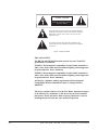
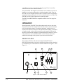
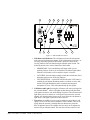
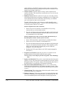
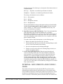
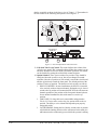
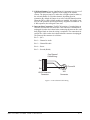
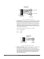
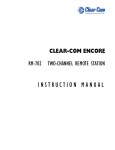
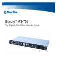
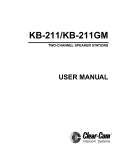
CLEAR-COM ENCORE
KB-702/KB-702GM TWO-CHANNNEL
SPEAKER STATIONS
INSTRUCTION MANUAL
KB-702/KB-702GM Two-Channel Speaker Stations Instruction Manual
Part Number: 810492Z Rev. 3
Legal Disclaimer
Copyright © 2013 HME Clear-Com Ltd.
All Rights Reserved
Clear-Com, the Clear-Com logo, and Clear-Com Concert are trademarks or registered trademarks of HM Electronics, Inc.
The software described in this document is furnished under a license agreement and may be used only in accordance with the
terms of the agreement.
The product described in this document is distributed under licenses restricting its use, copying, distribution, and decompilation/
reverse engineering. No part of this document may be reproduced in any form by any means without prior written authorization
of Clear-Com, an HME Company.
Clear-Com Offices are located in California, USA; Cambridge, UK; Montreal, Canada; and Beijing, China. Specific addresses
and contact information can be found on Clear-Com's corporate website:
www.clearcom.com
Clear-Com Contacts
Americas and Asia-Pacific Headquarters
California, United States
Tel: +1.510.337.6600
Email: [email protected]
Europe, Middle East, and Africa Headquarters
Cambridge, United Kingdom
Tel: +44 1223 815000
Email: [email protected]
Canada Office
Quebec , Canada
Tel: +1 (450) 653-9669
China Office
Beijing Representative Office
Beijing, P.R.China
Tel: +8610 65811360 / 65815577
CONTENTS
OPERATION . . . . . . . . . . . . . . . . . . . . . . . . . . . . . . . . . . 1-1
Introduction . . . . . . . . . . . . . . . . . . . . . . . . . . . . . . . . . . . . . . . . . . . . . . . . . 1-1
Description . . . . . . . . . . . . . . . . . . . . . . . . . . . . . . . . . . . . . . . . . . . . . . . . . . 1-1
Operation . . . . . . . . . . . . . . . . . . . . . . . . . . . . . . . . . . . . . . . . . . . . . . . . . . . 1-2
Front Panel . . . . . . . . . . . . . . . . . . . . . . . . . . . . . . . . . . . . . . . . . . . . . . . . 1-2
Internal Adjustments and Connections . . . . . . . . . . . . . . . . . . . . . . . . . . 1-5
INSTALLATION . . . . . . . . . . . . . . . . . . . . . . . . . . . . . . . 2-1
MAINTENANCE . . . . . . . . . . . . . . . . . . . . . . . . . . . . . . . 3-1
Block Diagram for the KB-702 . . . . . . . . . . . . . . . . . . . . . . . . . . . . . . . . . . 3-1
Block Diagram for the KB-702GM . . . . . . . . . . . . . . . . . . . . . . . . . . . . . . . 3-2
Troubleshooting . . . . . . . . . . . . . . . . . . . . . . . . . . . . . . . . . . . . . . . . . . . . . . 3-3
TECHNICAL SPECIFICATIONS . . . . . . . . . . . . . . . . . . 4-1
KB-702/KB-702GM Two-Channel Speaker Stations . . . . . . . . . . . . . . . . . 4-1
LIMITED WARRANTY. . . . . . . . . . . . . . . . . . . . . . . . . . 5-I
Warranty Period . . . . . . . . . . . . . . . . . . . . . . . . . . . . . . . . . . . . . . . . . . . . . . 5-i
Technical Support. . . . . . . . . . . . . . . . . . . . . . . . . . . . . . . . . . . . . . . . . . . . . 5-i
Warranty Repairs and Returns . . . . . . . . . . . . . . . . . . . . . . . . . . . . . . . . . . . 5-ii
Non-Warranty Repairs and Returns . . . . . . . . . . . . . . . . . . . . . . . . . . . . . . . 5-ii
Extended Warranty . . . . . . . . . . . . . . . . . . . . . . . . . . . . . . . . . . . . . . . . . . . . 5-ii
Service Contract . . . . . . . . . . . . . . . . . . . . . . . . . . . . . . . . . . . . . . . . . . . . . 5-iii
Liability . . . . . . . . . . . . . . . . . . . . . . . . . . . . . . . . . . . . . . . . . . . . . . . . . . . 5-iii
KB-702/KB-702GM
TWO-CHANNEL
i
ii
KB-702/KB-702GM TWO-CHANNEL SPEAKER
IMPORTANT SAFETY
INSTRUCTIONS
Please read and follow
these instructions before
operating this product.
1.
2.
3.
4.
5.
6.
7.
8.
9.
10.
11.
12.
13.
Read these instructions.
Keep these instructions.
Heed all warnings.
Follow all instructions.
Do not use this apparatus near water.
Clean only with dry cloth.
Do not block any ventilation openings. Install in accordance with the
manufacturer’s instructions.
Do not install near any heat sources such as radiators, heat registers,
stoves, or other apparatus (including amplifiers) that produce heat.
Only use attachments/accessories specified by the manufacturer.
Use only with the cart, stand, tripod, bracket, or table specified by the
manufacturer, or sold with the apparatus. When a cart is used, use caution
when moving the cart/apparatus combination to avoid injury from
tip-over.
Unplug this apparatus during lightning storms or when unused for long
periods of time.
Refer all servicing to qualified service personnel. Servicing is required
when the apparatus has been damaged in any way, such as power-supply
cord or plug is damaged, liquid has been spilled or objects have fallen into
the apparatus, the apparatus has been exposed to rain or moisture, does
not operate normally, or has been dropped.
WARNING: To reduce the risk of fire or electric shock, do not expose
this product to rain or moisture.
Please familiarize yourself with the safety symbols in Figure 1. When you
see these symbols on this product, they warn you of the potential danger
of electric shock if the station is used improperly. They also refer you to
important operating and maintenance instructions in the manual.
KB-702/KB-702GM TWO-CHANNEL
iii
CAUTION
RISK OF ELECTRIC SHOCK
DO NOT OPEN
This symbol alerts you to the presence of uninsulated dangerous
voltage within the product's enclosure that might be of sufficient
magnitude to constitute a risk of electric shock. Do not open
the product's case.
This symbol informs you that important operating and maintenance instructions are included in the literature accompanying
this product.
Figure 1: Safety Symbols
EMC AND SAFETY
The KB-702 and KB-702GM stations meet all relevant CE and FCC
specifications set out below:
EN55103-1 Electromagnetic compatibility. Product family standard for
audio, video, audio-visual, and entertainment lighting control apparatus
for professional use. Part 1: Emissions.
EN55103-2 Electromagnetic compatibility. Product family standard for
audio, video, audio-visual, and entertainment lighting control apparatus
for professional use. Part 2: Immunity.
And thereby compliance with the requirement of Electromagnetic
Compatibility Directive 2004/108/EC and Low Voltage Directive
2006/95/EC
This device complies with Part 15 of the FCC Rules. Operation is subject
to the following two conditions: (1) this device may not cause harmful
interference, and (2) this device must accept any interference received,
including interference that may cause undesired operation.
iv
KB-702/KB-702GM TWO-CHANNEL SPEAKER
OPERATION
INTRODUCTION
Congratulations and thank you for choosing this Clear-Com product. The
KB-702 and KB-702GM two-channel speaker stations are powerful,
user-friendly units that can serve as versatile intercom stations.
Please read this manual completely to better understand the functions of these
products. For questions not addressed in this manual, contact the dealer or
Clear-Com directly. Clear-Com applications support and service people are
ready to help.
DESCRIPTION
The Clear-Com KB-702 is a two-channel speaker station ideal for theatre, live
performances, industrial applications, and small TV facilities. It features
excellent speech intelligibility even in high-noise environments and can be
tailored to your needs through its programmable options.
In addition, the Clear-Com KB-702GM contains a jack for an optional
Clear-Com gooseneck panel microphone and a close-in, voice-controlled
circuit (VOX). This circuit allows automatic, alternate dipping of the panel
microphone and the speaker in response to conversation.
Selectable two-channel talking and/or listening allows the operator to
communicate on either of the intercom channels. The dual-action talk button
is electronic momentary or latching. Monitoring can be done through the
headset, the integral speaker, or both at once. The KB-702 offers both visual
and audible call signaling to attract the attention of operators. The remote mic
kill (RMK) feature on main stations will turn off any open mics on the
KB-702.
A balanced program input allows the monitoring of external audio using the
headset or speaker. This program input can also be used as a paging function.
The KB-702 speaker station accepts dynamic headsets. A sidetone control
allows the operator to vary the level of his/her own voice as heard in the
headset and speaker.
The integral speaker can be turned on or off by a convenient front panel
switch. An automatic speaker dipping circuit will lower the level of the
speaker whenever the talk button is activated. This feature helps minimize
acoustical feedback.
The KB-702 receives power from the Clear-Com intercom line. The unit
mounts either in a standard four-gang electrical outlet box or in an optional
Clear-Com four-gang V-box. The extra-thick front panel and compact
surface-mount circuitry maintains legendary Clear-Com ruggedness. The two
intercom channels connect to a plug-on screw terminal strip. Male and female
KB-702/KB-702GM
TWO-CHANNEL
1-1
3-pin XLR connectors are provided on the four-gang V-box for an inline
connection to one of the intercom channels.
The optional EB7-TW daughter board module can be installed to provide an
interface to two intercom channels on a single microphone cable. Also, the
EB7-4W four-wire daughter board module is available to allow long-distance
connections using separate pairs of wire for send audio and receive audio. The
EB7-4W four-wire option supports two-channel operation.
The KB-702 and KB-702GM are compatible with all Clear-Com party-line
intercoms.
OPERATION
Normal operation of the KB-702 speaker station requires access only to the
front panel controls. The controls located elsewhere on the unit are intended
to be set-and-forget in nature. For intercom operation, set the listen level
control to the desired level and press the talk button when talking. If a headset
or handset is used, set the sidetone control for each channel for the desired
amount of sidetone in the earphone. If a hand-held push-to-talk mic is used, or
if the panel mic is used on the KB-702GM, set the sidetone controls for
minimum feed-through to the speaker to prevent acoustic feedback.
FRONT PANEL
The controls, indicators, and connectors found on the KB-702 and
KB-702GM front panels are shown in the following figures and are described
by the following text. The numbers in the left column refer to Figure 1-1 and
Figure 1-2.
4
9
2
3
Channel Select
A
B
Call
Volume
Headset
Program Level
Off
Sidetone
Talk
On
Speaker
2-Channel
Speaker Station
KB-702
10
5
1
7
6
Figure 1-1: KB-702 Front Panel
1-2
KB-702/KB-702GM TWO-CHANNEL SPEAKER
11
12
8
9
2
Microphone
4
3
Channel Select
VOX
A
B
Volume
Panel Mic
Headset
Call
Headset
Program Level
Sidetone
Speaker
Off
On
Talk
2-Channel
Speaker Station
KB-702GM
10
5
1
7
6
Figure 1-2: KB-702GM Front Panel
1. Talk Button and Indicator: The talk button activates the microphone
feed to the selected intercom channel. It has a dual action (momentary or
latching) depending upon how the button is pressed. If desired, the
latching function can be defeated using an internal option switch. The
following describes the various functions of this button.
•
MOMENTARY: Press and hold the talk button while you are
speaking. Release it when you are finished. The button lights amber
when the talk function is active and blue when it is inactive.
•
LATCHING: Press the button quickly to latch the talk function. Press
the button again to turn off the talk function.
•
VOX INDICATION: On the KB-702GM, when the VOX feature is
enabled, the talk button illuminates amber to indicate an active talk,
and the VOX light illuminates amber to indicate that the panel
microphone is in use. This will automatically dip the speaker.
2. Call Button and Light: Pressing the call button will send a call signal on
the selected channel. All the call lights on that channel will then flash.
Call signals can also be sent while talking if required. The call button will
light when pressed, or whenever a call signal is present on the selected
channel. An internal option jumper can be set to allow the call button to
light when a call signal is present on either channel.
3. Tone Alert: An audible tone alert can be enabled to sound when a call
signal is received on the selected channel or either channel. This can be
useful when the operator’s attention has been drawn away from the
KB-702 indicator panel. The audible tone alert level can be adjusted or
turned off by an internal control. The tone alert will not sound if a call
KB-702/KB-702GM TWO-CHANNEL
1-3
signal originates at the KB-702 station or if the speaker on/off switch is
turned off. The tone alert plays through both the speaker and headset if the
speaker on/off switch is turned on.
4. Volume Control: Turn this control to set the volume required on the
speaker or headset. This control does not affect the tone alert level or the
program input level.
5. Sidetone Control: Sidetone is the level of your own voice that you hear
while talking on the intercom. Setting a comfortable level of sidetone will
ensure that the intercom line sounds alive and also helps you modulate
your voice relative to other voices on the line.
Typically, different sidetone null settings are needed depending upon
whether you are using the speaker. Use one of the following procedures
to correctly set the sidetone level control.
Sidetone Adjustment Procedure for Headset:
1. Set the intercom level control to a comfortable level by having
someone talk to you from another station.
2. Press the talk button and speak into the microphone while turning the
sidetone null control slowly back and forth until you hear your voice
at a comfortable level in the headset.
Sidetone Adjustment Procedure for Gooseneck Mic (KB-702GM only) or
hand-held push-to-talk mic with the speaker turned on:
1. Set the VOX control fully counterclockwise to disable this feature.
2. Set the intercom level control to a comfortable level.
3. Press the talk button and speak into the microphone while turning the
sidetone null control slowly back and forth. There should be a point
where your voice (and any accompanying acoustic feedback)
disappears. This is the null point.
4. Readjust the VOX control. (Refer to the VOX control paragraph in
this section.)
6. Program Level Control: Adjust the program level control to set the
program audio level heard in the headset or panel speaker.
Note: Do not force the trimpots past their stop points. This will damage
them.
7. Speaker On/Off Switch: The speaker on/off switch turns the front panel
speaker on or off. This switch also controls whether the tone alert is heard
through the speaker. The speaker volume will automatically dip whenever
the talk function is set, unless the VOX function is disabled.
8. Mic Select Switch (KB-702GM only): The mic select switch selects
whether the panel microphone or the headset microphone is active. If the
VOX feature is enabled, it is only operational when the panel microphone
is active.
9. Channel Switch: This switch selects whether the speaker station is active
on intercom channel A or channel B.
10. Headset Connector: The headset connector is located on the front panel.
All Clear-Com headsets are recommended for use with the KB-702. The
Clear-Com handheld push-to-talk microphone will also plug into the
1-4
KB-702/KB-702GM TWO-CHANNEL SPEAKER
headset connector. The following is a description of the characteristics of
a suitable headset:
Mic Type --- Dynamic; see technical specifications for details
Headphone --- Dynamic; see technical specifications for details
The wiring of the headset is to be as follows:
Pin 1 --- Mic common
Pin 2 --- Mic hot
Pin 3 --- Headphone common
Pin 4 --- Headphone hot
The mic and headphone wiring in the headset cord must be individually
shielded. Do not connect pins #1 and #3 together. Headset extension
cords or headset “Y” cables are not recommended because they will
increase crosstalk between channels.
11. Panel Mic Connector (KB-702GM only): Clear-Com recommends the
GM-9 and GM-18 plug-in panel microphones for use with the
KB-702GM. The GM-9 is 9 in. (23.04 cm) long and the GM-18 is 18 in.
(46.08 cm) long. Both are the electret type. The 1/4 in. (0.64 cm)phone
jack on the microphone mates with the panel mic receptacle on the front
panel of the KB-702GM.
To install a GM-9 or GM-18 microphone, use the following steps:
1. Remove the plastic plug from the jack, if present.
2. Check and unscrew the set screw in the mic mounting flange to make
sure it is clear of the threads in the bushing.
3. Screw the microphone into the bushing hand tight.
4. Turn the set screw on top of the mic mounting flange clockwise to
lock the microphone in place.
12. VOX Control (KB-702GM only): When the panel microphone is
selected on the KB-702GM, the VOX control should be adjusted for
proper operation. This control is located to the right of the panel mic
connector. Use a narrow flat blade screwdriver such as a greenie or
tweaker for this adjustment. When the adjustment is correctly set, the
VOX light illuminates amber when speaking into the panel microphone.
Turning the control clockwise makes the KB-702GM more sensitive to
your voice. The VOX feature can be disabled by turning the VOX control
fully counterclockwise.
INTERNAL ADJUSTMENTS AND CONNECTIONS
The controls and connectors found inside the KB-702 are shown in the
following figure and described by the following text. The controls can be
accessed without completely removing the panel from its wall box or V-Box
enclosure by removing the top two screws and loosening the bottom two
screws a few turns. Then lean the panel out from the wall. The controls will
KB-702/KB-702GM TWO-CHANNEL
1-5
then be accessible as shown in the lower view of Figure 1-3. The numbers in
the left column of the following descriptions refer to Figure 1-3.
18
17
P3 Must be
installed if
no option
P2 Must be
installed if
no option
P1 Call
on Both
15
P1 Call on
Selected
16
View from top
of KB-702
1 2 3
Front Panel
13
14
Figure 1-3: Internal Adjustments and Connections
13. Call Alert Tone Level Control: This control adjusts the volume of the
call alert tone sound. This is normally adjusted when the system is set up
and there should be no need to adjust it in normal operation. This feature
can be disabled by turning the control fully counterclockwise.
14. Option Switches: Three option switches are provided. They should be
configured when the system is set up, but are not changed in normal
operation. Note the on position of each switch is toward the circuit board
and the off position is toward the front panel. The default position of the
switches is in the off position. The function of each switch is as follows:
1. SINGLE CHANNEL: In some installations, the KB-702 is intended
to be used only with one intercom channel. Setting the single channel
switch to the on position will connect the KB-702 to the one intercom
channel regardless of the position of the front panel channel selector.
In two-channel installations, this switch must be set to the off
position.
2. LONG LINE: If a long cable run is unavoidable and approaches
700 ft. (213.5 m) or more, set the long line option switch to the on
position. The ability to set a sidetone null depends upon properly
setting this switch.
3. LATCH DISABLE: Setting the latch disable switch to the on position
will disable the latching function of the talk button. In this mode, the
talk button must be continuously pressed while the operator is talking.
1-6
KB-702/KB-702GM TWO-CHANNEL SPEAKER
15. Call Signal Jumper: In some installations it is important to receive a call
signal from either channel, regardless of the setting of the channel
selector. The plug-on jumper P1 makes the call light respond to either (a)
the selected channel or to (b)either channel, depending upon its
orientation. By default, the jumper is set to the selected channel position.
When the TW or 4-Wire Option modules are installed, this jumper is not
used. In TW operation, the call signal always originates on channel A. In
4-Wire operation, the call signal is not used.
16. Intercom Line Connection: The KB-702 contains a 5-terminal plug-on
connector for intercom line connection. This connector is intended to be
unplugged from the circuit board when connecting the intercom line, and
then plugged back on when the wiring is completed. The connections for
each pin are visible on the circuit board when the connector is unplugged.
The pinout of this connector is as follows:
Pin 1 --- (NC)
Pin 2 --- Channel A Audio
Pin 3 --- Channel B Audio
Pin 4 --- Power
Pin 5 --- Ground (Shield)
One Channel
Cable Wiring:
Pin 5
1
2
Pin 1
KB-702 Intercom
Connector
3 Channel A
XLR
Connector
Figure 1-4: One-Channel Cable Wiring
KB-702/KB-702GM TWO-CHANNEL
1-7
Two Channel
Cable Wiring
1
Pin 5
3
Channel B
3
Channel A
2
1
Pin 1
KB-702 Intercom
Connector
2
XLR
Connectors
Figure 1-5: Two-Channel Cable Wiring
17. Program Input: A 3-terminal plug-on connector provides the program
input to the station. Program is fed to the headset and speaker. The level to
the speaker or headset is controlled by the program level control. The
program input accepts a balanced or unbalanced line-level audio signal.
If this input is connected to the stage announce (SA) output of a main
station it can be used as a paging input. Since the level of this input is
independently adjustable from the intercom audio volume, it can be used
to override the intercom audio.
The pinout of the program input connector is as follows:
Pin 1 --- Ground (shield)
Pin 2 --- + Signal
Pin 3 --- - Signal
Program Input
Cable Wiring
Pin 3
1
Pin 1
2
KB-702 Program
Input Connector
3
XLR
Connector
Figure 1-6: Program-Input Cable Wiring
18. Option Board Jumpers: The three jumper plugs P1, P2, and P3 must be
installed when optional modules are not used. When the optional
EB7-4W four-wire or EB7-TW modules are used, both P1 and P3 must
be removed. In the KB-702GM, P2 is replaced by the VOX module. Save
these jumper plugs for possible future use after removing them. The
KB-702 will not operate without either these jumper plugs or the
optional modules installed.
1-8
KB-702/KB-702GM TWO-CHANNEL SPEAKER
KB-702/KB-702GM TWO-CHANNEL
1-9
1-10
KB-702/KB-702GM TWO-CHANNEL SPEAKER
INSTALLATION
1. Unpack the unit and inspect for any damage that may have occurred in
shipping.
2. Set the option switches to the default (up) position.
3. Connect the intercom lines. If only one intercom line is to be connected,
turn option switch #1 to the on or closed position.
4. Install the KB-702 into the four-gang outlet box or V-box. (For additional
information, refer to the Clear-Com System Installation Manual.)
5. Set listen levels and sidetones. (Refer to the listen level and sidetone
setting topics in the Operation chapter of this manual.)
6. The speaker station should now be operating properly.
7. Read the rest of this manual for further information.
KB-702/KB-702GM
TWO-CHANNEL
2-1
2-2
KB-702/KB-702GM TWO-CHANNEL SPEAKER
MAINTENANCE
This chapter provides maintenance information including block diagrams and tips for solving problems.
Caution: These servicing instructions are for use by qualified personnel only. To reduce the risk of electrical
shock, do not perform any servicing other than that contained in the operating instructions unless you
are qualified to do so.
BLOCK DIAGRAM FOR THE KB-702
EQ/
LIM
Sidetone
Null
Intercom
Volume
Headset
Mic
SpeakerSpeaker
On/Off
Speaker
Dip
Mic
Mute
Long Line
Headset
Output
Talk
Talk
Program
Mute
Call Alert Program
Tone Level Level
Microprocessor
Call
Latch
Disable
Call
Light
Call Send &
Receive
Power
RMK
Balanced
Program
Input
Channel
Switch
TW Option
Single
Chan.
Common
+30 VDC
Ch. B
Ch. A
Ground
Ch. B
4-Wire
Input
16 VAC
Rectifier
Power
Ch. A
2-Wire / 4-Wire
Select
Ch. B
4-Wire
Output
4-Wire
Option
Ch. A
Figure 3-7: KB-702 Block Diagram
KB-702/KB-702GM
TWO-CHANNEL
3-1
BLOCK DIAGRAM FOR THE KB-702GM
Headset
Mic
EQ/
LIM
Sidetone
Null
Intercom
Volume
Mic Select
SpeakerSpeaker
On/Off
Speaker
Dip
Panel
Mic
Mic Dip /
Mute
Long Line
Headset
Output
VOX
Talk/
VOX
Talk
Program
Mute
Red /
Green
Call Alert Program
Tone Level Level
Microprocessor
Call
Latch
Disable
Call
Light
Call Send &
Receive
Power
RMK
Balanced
Program
Input
Channel
Switch
TW Option
Single
Chan.
Common
+30 VDC
Ch. B
Ch. A
Ground
Ch. B
4-Wire
Input
16 VAC
Rectifier
Power
Ch. A
2-Wire / 4-Wire
Select
Ch. B
4-Wire
Output
4-Wire
Option
Ch. A
Figure 3-8: KB-702GM Block Diagram
3-2
KB-702/KB-702GM TWO-CHANNEL SPEAKER STATIONS
TROUBLESHOOTING
SYMPTOM
System does not operate. Talk
button does not light.
CAUSE
SOLUTION
No intercom connection to the
KB-702. If the EB7-4W four-wire
option module is connected, the
KB-702 may not be receiving AC
power.
Check connections and cable.
The KB-702 has an internal failure.
Unit requires servicing.
Speaker switch turned off, volume
knob turned all the way down, or
channel switch set to unused
channel.
Adjust controls appropriately.
Speaker plug or wiring has come
loose.
Make sure speaker is connected
internally.
Plug P3 missing on circuit board.
Plug P3 must be installed in jack J3
if the EB-TW or EB7-4W options
are not used.
Hum or buzz in system
Inductive pickup caused by close
proximity of this speaker station or
connected stations to power lines or
transformers.
Relocate the offending unit or
wiring. If the cable run is
exceptionally long, consider adding
and using the EB7-4W four-wire
option module. (Requires an
additional four-wire interface at the
opposite end of the “long run.”)
System feedback (Acoustical)
Intercom level control at this station
or another station is set too high.
Adjust.
Sidetone null control at this station
or another station is not adjusted
correctly.
Adjust. Refer to the chapter
“Operation.”
Channel not terminated.
Set the main station or power supply
termination switch for that channel
to the on position.
Channel switch set to an
unconnected channel.
If only one intercom line is
connected, set option switch #1 to
the on or closed position to link both
channel switch positions to the same
intercom line.
A headset extension cord was used.
Headset extension cords are not
recommended.
Speaker does not operate. Talk
button lights amber when
pressed.
KB-702/KB-702GM TWO-CHANNEL SPEAKER STATIONS
3-3
SYMPTOM
CAUSE
VOX problems (KB-702GM
only)
SOLUTION
Stays tripped (amber light on).
Sensitivity set too high.
Turn VOX sensitivity control in a
counter-clockwise direction.
Will not trip with voice. Sensitivity
set too low.
Turn VOX sensitivity control in a
clockwise direction.
Note: VOX is intended for close-in
operation.
Excessive crosstalk
Program signal sounds
distorted.
Call signal does not function.
3-4
High DC resistance has a ground
return.
Use heavier cable; add additional
conductor(s) to ground return. If the
cable run is exceptionally long,
consider adding and using the
EB7-4W four-wire option module.
Multi-channel cable pairs are not
individually shielded.
Replace cable with individually
shielded pairs.
Headset cables are not wired
properly or shielded properly.
Correct wiring. Use headsets with
properly shielded wiring. Refer to
the chapter “Operation.”
Program level control set too high.
Turn the program level control
counter-clockwise.
Overload of program input circuit.
Reduce the gain of the program
signal at the source, such as an audio
mixer.
Excessive DC loading of intercom
line.
Remove any audio transformers or
other equipment that may be
connected across the intercom line.
If equipment other than Clear-Com
intercom equipment must be
connected to the intercom line,
please contact Clear-Com
application or service personnel for
information or recommendations.
Far too many terminations on the
intercom line.
Check all main stations and power
supplies to make sure each intercom
channel is terminated at only one
point.
Plug P1 missing on circuit board.
Plug P1 must be installed in jack J1
if the EB7-4W or EB7-TW options
are not used.
KB-702/KB-702GM TWO-CHANNEL SPEAKER STATIONS
3-5
KB-702/KB-702GM TWO-CHANNEL SPEAKER STATIONS
3-6
KB-702/KB-702GM TWO-CHANNEL SPEAKER
TECHNICAL
SPECIFICATIONS
KB-702/KB-702GM TWO-CHANNEL
SPEAKER STATIONS
dBu is an absolute measurement. 0 dBu is referenced to 0.775 volts RMS
Panel Microphone Input (KB-702GM)
Input Type
Input Impedance
Mic Limiter Threshold
Mic Limiter Range
Headset Microphone Input
Input Type
Input Impedance
Mic Limiter Threshold
Mic Limiter Range
Program Line Input
Maximum Level before Clipping
Input Impedance
Headset Output
Load Impedance
Output Impedance
Output Limiter Threshold
Maximum Output Level before Distortion
Speaker Output
Load Impedance
Max Output Level before 1% Distortion
Party Line Output
Off Noise
Output Impedance
Party Line Input
Crosstalk
Max level before Clipping
Sidetone Null Capability (KB-702GM only)
KB-702/KB-702GM TWO-CHANNEL SPEAKER STA-
Electret
>=2KΩ
-2dBu ±3dB
>= 15dB
Dynamic
>= 1KΩ
-2dBu ± 3dB
>= 15dB
>= 20dBu
>= 5KΩ
>= 8Ω
<= 25Ω
+5dBu ± 3dB
>= 17dBu
>= 4Ω
20dBu ± 2dBu
< -74dBu
>10KΩ
< -60dB
>= 12dBu
> 25dB
4-1
Frequency Response
Panel Mic - Party Line (KB-702GM only)
Headset Mic - Party Line
Program Input - Headset Out
Program Input - Speaker Out
Party Line - Headset Out
Party Line - Speaker Out
Max Distortion
Panel Mic - Party Line (KB-702GM only)
Headset Mic - Party Line
Program Input - Headset Out
Program Input - Speaker Out
Party Line - Headset Out
Party Line - Speaker Out
Noise
Panel Mic - Party Line (KB-702GM only)
Headset Mic - Party Line
Program Input - Headset Out
Program Input - Speaker Out
Party Line - Headset Out
Party Line - Speaker Out
Max Gain
Panel Mic - Party Line (KB-702GM only)
Headset Mic - Party Line
Program Input - Headset Out
Program Input - Speaker Out
Party Line - Headset Out
Party Line - Speaker Out
Power
Input Voltage Range
Input Current (Idle)
Input Current (Max)
300 - 16KHz ± 3dB
300 - 15KHz ± 3dB
200 - 18KHz ± 3dB
200 - 18KHz ± 3dB
200 - 18KHz ± 3dB
200 - 18KHz ± 3dB
<= 0.5%
<= 0.5%
<= 0.2%
<= 0.5%
<= 0.2%
<= 0.5%
< -65dBu
< -70dBu
< -60dBu
< -60dBu
< -50dBu
< -50dBu
>= 37dB
41dB ± 2dB
>= 18dB
>= 24dB
>= 34dB
>= 40dB
20-30 VDC
<= 90mA
<=110mA
Internal Adjustments and Connections
Intercom: Line
Program Input
Option Switches
Call Signal Jumper3
Call Alert Tone Level Control
4-2
Five terminal connector
Three terminal connector
Three DIP switches
Three sets of options jumpers
Level adjustment control
KB-702/KB-702GM TWO-CHANNEL SPEAKER
Front Panel Connectors
Panel Mic: (KB-702GM only)
Headset:
(1) 1/4 in. (0.64 cm) panel
mounting jack
(1) XLR-4M
Front Panel Controls & Indicators (KB-702GM)
(1) Panel / headset mic switch
(1) Program monitor level control
(1) Sidetone null control
(1) Talk button
(1) Call button
(1) Speaker ON-OFF switch
(1) Channel select switch
(1) Speaker volume control
(1) VOX control
(1) VOX indicator
Front Panel Controls & Indicators (KB-702)
(1) Program monitor level control
(1) Sidetone null control
(1) Talk button
(1) Call button
(1) Speaker ON-OFF switch
(1) Channel select switch
(1) Speaker volume control
Environmental
Dimensions (KB-702/KB-702GM)
Weight
KB-702
KB-702GM
32 - 122o F (0 - 50o C)
8.25 in. W x 4.5 in. H x 1.75 in. D
(210 mm x 114 mm x 44 mm)
0.99 lbs. (0.45 Kg)
1.1 lbs.(0.50 Kg)
Notice About Specifications
While Clear-Com makes every attempt to maintain the accuracy of the
information contained in its product manuals, that information is subject to
change without notice. Performance specifications included in this manual
are design-center specifications and are included for customer guidance and
to facilitate system installation. Actual operating performance may vary.
KB-702/KB-702GM TWO-CHANNEL
4-3
4-4
KB-702/KB-702GM TWO-CHANNEL SPEAKER
LIMITED
WARRANTY
Clear-Com offers 24 x 7
customer support if you
have an Extended
Warranty or Service
Contract.
Return Material
Authorization (RMA)
numbers are required for
all returns.
Both warranty and
non-warranty repairs are
available.
Clear-Com warrants that at the time of purchase, the equipment supplied
complies with any specification in the order confirmation when used under
normal conditions, and is free from defects in workmanship and materials
during the warranty period.
During the warranty period Clear-Com, or any service company authorized by
Clear-Com, will in a commercially reasonable time remedy defects in
materials, design, and workmanship free of charge by repairing, or should
Clear-Com in its discretion deem it necessary, replacing the product in
accordance with this limited warranty. In no event will Clear-Com be
responsible for incidental, consequential, or special loss or damage, however
caused.
WARRANTY PERIOD
The product may consist of several parts, each covered by a different warranty
period. The warranty periods are:
• Cables, accessories, components, and consumable items have a limited
warranty of 90 days.
• Headsets, handsets, microphones, and spare parts have a limited warranty
of one year.
• UHF wireless IFB products have a limited warranty of one year.
• UHF wireless intercom systems have a limited warranty of three years.
• All other Clear-Com and Drake brand systems and products, including
beltpacks, have a limited warranty of two years.
The warranty starts at the time of the product’s original purchase. The
warranty start date for contracts which include installation and
commissioning will commence from the earlier of date of the Site Acceptance
Test or three months from purchase.
TECHNICAL SUPPORT
To ensure complete and timely support to its customers, Clear-Com’s User
Support Center is staffed by qualified technical personnel. Telephone and
email technical support is offered worldwide by the User Support Center.
The User Support Center is available to Clear-Com’s customers during the
full course of their warranty period. Telephone support during the warranty
WARRANTY
i
period will be offered at no charge between 09:00 and 17:00 according to the
customer’s local time zone.
In addition, for customers who purchase an Extended Warranty or Service
Contract, 24-hour customer support is offered immediately upon purchase of
such agreement. For more information, contact your authorized dealer,
distributor, or sales representative.
Instructions for reaching Clear-Com’s User Support Centers are given below.
Americas and Asia-Pacific Headquarters California, United States Tel:
+1.510.337.6600 Email: [email protected]
Europe, Middle East, and Africa Headquarters Cambridge, United
Kingdom Tel: +44 1223 815000 Email: [email protected]
Canada Office Quebec , Canada Tel: +1 (450) 653-9669
China Office Beijing Representative Office Beijing, P.R.China Tel: +8610
65811360 / 65815577
Once the standard warranty period has expired, the User Support Center will
continue to provide telephone support if you have purchased an Extended
Warranty or Service Contract. In these cases, you will have access to
telephone support 24 hours per day, 7 days per week.
WARRANTY REPAIRS AND RETURNS
Before returning equipment for repair, contact a User Support Center to obtain
a Return Material Authorization (RMA). Clear-Com representatives will give
you instructions and addresses for returning your equipment. You must ship
the equipment at your expense, and the support center will return the
equipment at Clear-Com’s expense.
For out-of-box failures, use the following contact information:
Americas and Asia-Pacific Headquarters California, United States Tel:
+1.510.337.6600 Email: [email protected]
Europe, Middle East, and Africa Headquarters Cambridge, United
Kingdom Tel: +44 1223 815000 Email: [email protected]
Canada Office Quebec , Canada Tel: +1 (450) 653-9669
China Office Beijing Representative Office Beijing, P.R.China Tel: +8610
65811360 / 65815577
ii
WARRANTY
Clear-Com has the right to inspect the equipment and/or installation or
relevant packaging.
NON-WARRANTY REPAIRS AND RETURNS
For items not under warranty, you must obtain an RMA by contacting the
User Support Center. Clear-Com representatives will give you instructions
and addresses for returning your equipment.
You must pay all charges to have the equipment shipped to the support center
and returned to you, in addition to the costs of the repair.
EXTENDED WARRANTY
If you purchase an Extended Warranty, you are also given access free of
charge to the User Support Center 24 hours a day, 7 days a week.
You can purchase an extended warranty at any time during the first two years
of ownership of the product. The purchase of an extended warranty extends to
five years the warranty of any product offered with a standard two-year
warranty. The total warranty period will not extend beyond five years. Any
purchase of an extended warranty provides 24 x 7 customer support in
addition to the warranty immediately upon purchase of the warranty
extension.
Note: Clear-Com does not offer warranty extensions on UHF wireless
intercom systems, or on any product with a 1-year or 90-day warranty.
SERVICE CONTRACT
Clear-Com also offers service contracts that provide 24 x 7 telephone support,
advance replacements, training, proactive maintenance, on-site visits, and no
charge for repair or replacement of equipment. For more information, contact
your authorized dealer, distributor, or sales representative.
LIABILITY
THE FOREGOING WARRANTY IS CLEAR-COM'S SOLE AND
EXCLUSIVE WARRANTY. THE IMPLIED WARRANTY OF
MERCHANTABILITY AND FITNESS FOR A PARTICULAR PURPOSE
AND ANY OTHER REQUIRED IMPLIED WARRANTY SHALL EXPIRE
AT THE END OF THE WARRANTY PERIOD. THERE ARE NO OTHER
WARRANTIES (INCLUDING WITHOUT LIMITATION WARRANTIES
FOR CONSUMABLES AND OTHER SUPPLIES) OF ANY NATURE
WHATSOEVER, WHETHER ARISING IN CONTRACT, TORT,
NEGLIGENCE OF ANY DEGREE, STRICT LIABILITY OR
OTHERWISE, WITH RESPECT TO THE PRODUCTS OR ANY PART
THEREOF DELIVERED HEREUNDER, OR FOR ANY DAMAGES
AND/OR LOSSES (INCLUDING LOSS OF USE, REVENUE, AND/OR
PROFITS). SOME STATES DO NOT ALLOW THE EXCLUSION OR
WARRANTY
iii
LIMITATION OF INCIDENTAL OR CONSEQUENTIAL DAMAGES OR
THE LIMITATION ON HOW LONG AN IMPLIED WARRANTY LASTS,
SO THE ABOVE LIMITATIONS MAY NOT APPLY TO YOU. IN ANY
EVENT, TO THE MAXIMUM EXTENT PERMITTED UNDER
APPLICABLE LAW, CLEAR-COM'S LIABILITY TO CUSTOMER
HEREUNDER SHALL NOT UNDER ANY CIRCUMSTANCES EXCEED
THE COST OF REPAIRING OR REPLACING ANY PART(S) FOUND TO
BE DEFECTIVE WITHIN THE WARRANTY PERIOD AS AFORESAID.
This warranty does not cover any damage to a product resulting from cause
other than part defect and malfunction. The Clear-Com warranty does not
cover any defect, malfunction, or failure caused beyond the control of
Clear-Com, including unreasonable or negligent operation, abuse, accident,
failure to follow instructions in the manual, defective or improperly
associated equipment, attempts at modification and repair not approved by
Clear-Com, and shipping damage. Products with their serial numbers
removed or defaced are not covered by this warranty.
This warranty does not include defects arising from installation (when not
performed by Clear-Com), lightning, power outages and fluctuations, air
conditioning failure, improper integration with non-approved components,
defects or failures of customer furnished components resulting in damage to
Clear-Com provided product.
This limited warranty is not transferable and cannot be enforced by anyone
other than the original consumer purchaser.
This warranty gives you specific legal rights and you may have other rights
which vary from country to country.
iv
WARRANTY