1
dt
VT520/VT525 Video Terminal
Programmer Information
Order Number: EK-VT520-RM. A01
July 1994
Digital Equipment Corporation makes no representations that the use of its products in the
manner described in this publication will not infringe on existing or future patent rights, nor do
the descriptions contained in this publication imply the granting of licenses to make, use, or sell
equipment or software in accordance with the description.
DEC, OpenVMS, VT, and the DIGITAL logo are trademarks of Digital Equipment Corporation.
ADDS is a trademark of Applied Digital Data Systems, Inc.
IBM, ProPrinter, and PS/2 are registered trademarks of International Business Machines
Corporation.
MS–DOS is a registered trademark and Windows is a trademark of Microsoft Corporation.
SCO is a trademark of Santa Cruz Operations, Inc.
TVI is a trademark of TeleVideo, Inc.
UNIX is a registered trademark of UNIX System Laboratories, Inc.
WY and WYSE are registered trademarks of Wyse Technologies.
All other trademarks and registered trademarks are the property of their respective holders.
The Energy Star emblem does not represent EPA endoresement of any product or service.
Copyright © Digital Equipment Corporation 1994. All Rights Reserved.
Printed in U.S.A.
For copies of manuals, contact your local sales office.
This document was prepared using VAX DOCUMENT Version 2.1.
Preface
Introduction
This manual provides detailed information for advanced users, consultants, and
programmers. This manual has the following parts, chapters, and appendices:
•
•
•
Part I, VT520 Video Terminal
•
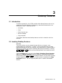
Chapter 1, Overview
•
Chapter 2, Set-Up
•
Chapter 3, Desktop Features
Part II, VT520 ANSI Mode
•
Chapter 4, ANSI Control Functions Summary
•
Chapter 5, ANSI Control Functions
•
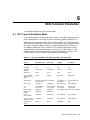
Chapter 6, SCO Console Emulation
•
Chapter 7, Character Sets
•
Chapter 8, Keyboard Processing
•
Chapter 9, Communications
•
Chapter 10, Printer Port
Part III, VT520 ASCII Emulation
•
Chapter 11, ASCII Emulations and Control Functions
•
Chapter 12, ASCII Escape Sequences
•
Chapter 13, Defining and Loading ASCII Character Fonts
•
Appendix A, VT Keyboard Legend Data
•
Appendix B, Enhanced PC Keyboards
•
Appendix C, ASCII Keycodes and Local Functions
•
Appendix D, VT520 Termcap Data
•
Appendix E, ANSI Control Function Index
iii
Conventions
The following conventions are used in this manual:
Set-Up features
Alt/Ctrl/Print Screen
Characters in control
functions
Terminal Set-Up menu selections appear in boldface type.
Multiple keys are separated by a slash (/) and should be
pressed in combination. That is, all three keys Alt , Ctrl , and
Print Screen are pressed down at the same time.
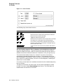
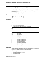
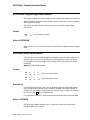
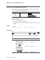
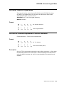
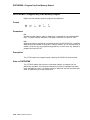
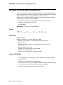
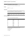
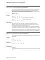
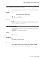
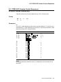
Control function characters are in boldface type. Below
each character is a column/row number that indicates the
character’s position in a standard code table. For example:
ESC
#
6
1/11
2/3
3/6
(=
(=
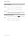
Parameters
Parameters appear in italic type.
Note
Provides general information.
Control function
Column/row numbers
How to Use This Manual
The VT520 Video Terminal Programmer Information is written for four audiences:
an advanced user, who needs to know more about the terminal Set-Up features;
a programmer, who develops application programs; a software product support
person, who provides assistance to application programmers and users; and a
hardware systems engineer, who need more information on terminal connections.
Advanced User
If you have read the VT520 Video Terminal Installation and Operating
Information manual and need more information on the the terminal Set-Up
features, you may wish to refer to the following:
•
Index
•
Chapter 1—Overview—Provides a brief summary of the product.
•
Chapter 2—Set-Up—Describes each entry in the Set-Up menus in the order
that is displayed in the terminal.
•
Chapter 3—Desktop Features—Provides a more in-depth description of the
desktop features of the terminal.
•
Chapter 6—Keyboard Processing—Describes the differences in the types
of keyboard layouts supported, local functions, and accessibility aids.
Programmer
If you are using ANSI control functions for your program, then you may wish to
start with Part II of the manual:
iv
•
Chapter 4—ANSI Control Function Summary— Provides a tutorial
section on Control Functions and information on designing and down-line
loading a Soft Character set (soft font). In this chapter, the Control Functions
are grouped according to the task to be performed. The information on each
Control Function is very brief. If you need more information, the mnemonic
at the end of the line item refers to a command section in Chapter 5.
•
Chapter 5—ANSI Control Functions—Provides in-depth information on
each control function listed in alphabetic order according to the mnemonic.
•
Chapter 2—Set-Up—Lists the Set-Up factory defaults at the end of this
chapter, with their host control code mnemonic.
•
Chapter 6—Keyboard Processing—Describes the keyboard layouts,
keyboard-to-host interface, keypad sequences, local functions, LEDs controls,
languages, accents, scan codes, and control codes.
•
Chapter 9—Communications—Describes the serial communications from
the terminal to the host ports and the hardware and software handshaking.
•
Chapter 10—Printer Port—Describes the parallel printer port and the
switching sequences for the modes supported.
•
Appendix A—VT Keyboard Legend Data
•
Appendix B—Enhanced PC Keyboard Legend Data
•
Appendix D—VT500 Termcap Data
If you are developing a application program for a SCO Console, then you may
wish to refer to:
•
Chapter 6—SCO Console Emulation—Describes the SCO Console mode,
including the Control Functions relative to the SCO Console applications.
If you are using ASCII control functions for your program, then you may wish to
start with Part III of the manual:
•
Chapter 11—ASCII Emulations and Control Functions— Provides an
overview of the ASCII emulation, the coding notation, and the symbols used
in the ASCII sequence tables.
•
Chapter 12—ASCII Escape Sequences—Summarizes the ASCII escape
and control sequences for the various ASCII emulation modes, according to
the task to be performed.
•
Chapter 13—Defining and Loading ASCII Character Fonts – Provides
specific information on loading font banks and designing an ASCII character
font.
•
Appendix C—ASCII Keycodes and Local Functions
Software Product Support
If you are helping a user or programmer with an application, then you may wish
to refer to the following:
•
Appendix E—ANSI Control Function Index—Lists the control functions
by their final character, which makes them easier to find in a program. The
mnemonic at the end of the line item refers to a command in Chapter 5, listed
in alphabetic order.
•
Index—Lists control functions by mnemonic or by name and lists other
subjects by topic.
•
Chapter 5—ANSI Control Functions—Provides in-depth information on
specific control functions.
•
Chapter 6—Keyboard Processing—Lists the scan codes Make and Break
sequences.
•
Appendix D—VT500 Termcap Data—Provides the Termcap information for
ANSI emulations.
v
Hardware Systems Engineer
If you are helping a user to install the terminal or to operate within a specific
environment, then you may wish to refer to the following:
vi
•
Index—Search by topic.
•
Chapter 1—Overview Provides a brief summary of the product.
•
Chapter 2—Set-Up Describes each entry in the order that is displayed in
the terminal, starting with the Actions menu and lists the modes supported.
Also lists the Set-Up factory defaults.
•
Chapter 9—Communications—Describes the serial communications from
the terminal to the host ports, pin numbers and signals, and the hardware
and software handshaking.
•
Chapter 10—Printer Port—Describes the parallel printer port, pin numbers
and signals, and modes supported.
Contents
Preface . . . . . . . . . . . . . . . . . . . . . . . . . . . . . . . . . . . . . . . . . . . . . . . . . . . . . . . . . . . .
iii
Part I VT520 Video Terminal
1 Overview
1.1
1.2
1.3
1.4
1.5
1.5.1
1.5.2
1.6
1.7
1.8
1.9
1.10
1.11
Introduction . . . . . . . . . . . . . . . . . . . . . .
Communications Features . . . . . . . . . . .
Keyboard Features . . . . . . . . . . . . . . . . .
Printer Port Features . . . . . . . . . . . . . . .
Display and Text Capabilities . . . . . . . .
ANSI . . . . . . . . . . . . . . . . . . . . . . . .
ASCII . . . . . . . . . . . . . . . . . . . . . . . .
Enhanced Set-Up . . . . . . . . . . . . . . . . . .
Desktop Productivity Features . . . . . . . .
Character Set Support . . . . . . . . . . . . . .
Ergonomics (Human Factors) Features .
Field-Upgradable Firmware . . . . . . . . . .
Comparison with previous VT Terminals
.
.
.
.
.
.
.
.
.
.
.
.
.
.
.
.
.
.
.
.
.
.
.
.
.
.
..
..
..
..
..
..
..
..
..
..
..
..
..
.
.
.
.
.
.
.
.
.
.
.
.
.
.
.
.
.
.
.
.
.
.
.
.
.
.
.
.
.
.
.
.
.
.
.
.
.
.
.
.
.
.
.
.
.
.
.
.
.
.
.
.
.
.
.
.
.
.
.
.
.
.
.
.
.
.
.
.
.
.
.
.
.
.
.
.
.
.
..
..
..
..
..
..
..
..
..
..
..
..
..
.
.
.
.
.
.
.
.
.
.
.
.
.
.
.
.
.
.
.
.
.
.
.
.
.
.
.
.
.
.
.
.
.
.
.
.
.
.
.
.
.
.
.
.
.
.
.
.
.
.
.
.
.
.
.
.
.
.
.
.
.
.
.
.
.
.
.
.
.
.
.
.
.
.
.
.
.
.
..
..
..
..
..
..
..
..
..
..
..
..
..
.
.
.
.
.
.
.
.
.
.
.
.
.
.
.
.
.
.
.
.
.
.
.
.
.
.
.
.
.
.
.
.
.
.
.
.
.
.
.
.
.
.
.
.
.
.
.
.
.
.
.
.
.
.
.
.
.
.
.
.
.
.
.
.
.
.
.
.
.
.
.
.
.
.
.
.
.
.
1–1
1–1
1–2
1–3
1–3
1–3
1–3
1–4
1–4
1–4
1–4
1–5
1–6
.
.
.
.
.
.
.
.
.
.
.
.
.
.
.
.
.
.
.
.
.
.
.
.
.
.
.
.
.
.
.
.
.
.
.
.
.
.
.
.
.
.
.
.
.
.
.
.
.
.
.
.
.
.
.
.
.
.
.
.
.
.
.
.
.
.
.
.
.
.
.
.
.
.
.
.
.
.
.
.
.
.
.
.
.
.
.
.
.
.
.
.
.
.
.
.
.
.
.
.
.
.
.
.
.
.
.
.
.
.
.
.
.
.
.
.
.
.
.
.
.
.
.
.
.
.
.
.
.
.
.
.
.
.
.
.
.
.
.
.
.
.
.
.
.
.
.
.
.
.
.
.
.
.
.
.
.
.
.
.
.
.
.
.
.
.
.
.
.
.
.
.
.
.
.
.
.
.
.
.
.
.
.
.
.
.
.
.
.
.
.
.
.
.
.
.
.
.
.
.
.
.
.
.
.
.
.
.
.
.
.
.
.
.
.
.
.
.
.
.
.
.
.
.
.
.
.
.
.
.
.
.
.
.
.
.
.
.
.
.
.
.
.
.
.
.
.
.
.
.
.
.
.
.
.
.
.
.
.
.
.
.
.
.
.
.
.
.
.
.
.
.
.
.
.
.
.
.
.
.
.
.
.
.
.
.
.
.
.
.
.
.
.
.
.
.
.
.
.
.
.
.
.
.
.
.
.
.
.
.
.
.
.
.
.
.
.
.
.
.
.
.
.
.
.
.
.
.
.
.
.
.
.
.
.
.
.
.
.
.
.
.
.
.
.
.
.
.
.
.
.
.
.
.
.
.
.
.
.
.
.
.
.
.
.
.
.
.
.
.
.
.
.
.
.
.
.
.
.
.
.
.
.
.
.
.
.
.
.
.
.
.
.
.
.
.
.
.
.
.
.
.
.
.
.
.
.
.
.
.
.
.
.
.
.
.
.
.
.
.
.
.
.
.
.
.
.
.
.
.
.
.
.
.
.
.
.
.
.
.
.
.
.
.
.
.
.
.
.
.
.
.
.
.
.
.
.
.
.
.
.
.
2–1
2–2
2–2
2–2
2–3
2–3
2–5
2–5
2–6
2–6
2–7
2–8
2–8
2–9
2–9
2–9
2–9
2–9
2–9
2–10
2–10
2–11
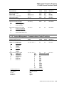
2 Set-Up
2.1
2.1.1
2.1.2
2.1.3
2.1.4
2.1.5
2.1.6
2.1.7
2.1.8
2.1.9
2.2
2.3
2.3.1
2.3.2
2.3.3
2.3.4
2.4
2.4.1
2.4.2
2.4.3
2.4.4
2.4.5
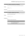
Entering Set-Up . . . . . . . . . . . . . . . . . . . . .
Effects of Entering Set-Up . . . . . . . . . .
Set-Up Languages . . . . . . . . . . . . . . . .
Power-On Settings and Defaults . . . . .
Self-test Error Messages . . . . . . . . . . .
Context Sensitivity . . . . . . . . . . . . . . . .
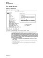
Set-Up Summary Line . . . . . . . . . . . . .
Set-Up Status Messages . . . . . . . . . . . .
Status Line . . . . . . . . . . . . . . . . . . . . .
Keyboard Indicator Line . . . . . . . . . . .
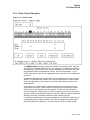
Set-Up Screen Text . . . . . . . . . . . . . . . . . .
Main Menu . . . . . . . . . . . . . . . . . . . . . . . .
On-Line . . . . . . . . . . . . . . . . . . . . . . . .
Save Settings . . . . . . . . . . . . . . . . . . . .
Restore Settings . . . . . . . . . . . . . . . . . .
Exit Set-Up . . . . . . . . . . . . . . . . . . . . .
Actions Menu . . . . . . . . . . . . . . . . . . . . . . .
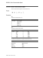
Clear Display . . . . . . . . . . . . . . . . . . . .
Clear Communications . . . . . . . . . . . . .
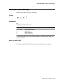
Reset this Session . . . . . . . . . . . . . . . .
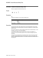
Restore Factory Defaults . . . . . . . . . . .
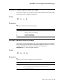
Clock, Calculator, Show Character Sets
.
.
.
.
.
.
.
.
.
.
.
.
.
.
.
.
.
.
.
.
.
.
.
.
.
.
.
.
.
.
.
.
.
.
.
.
.
.
.
.
.
.
.
.
.
.
.
.
.
.
.
.
.
.
.
.
.
.
.
.
.
.
.
.
.
.
vii
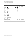
2.4.6
Banner Message . . . . . . . . . . . . . . . . . . . . . . . . . . . . . . . . . . . . . . . . . .
2.5
Multiple Sessions . . . . . . . . . . . . . . . . . . . . . . . . . . . . . . . . . . . . . . . . . . . .
2.5.1
Enabling and Controlling the Session Configuration . . . . . . . . . . . . . .
2.5.2
Multiple Sessions using a Terminal Server with TD/SMP . . . . . . . . . .
2.5.3
Multiple Sessions using SSU Host Software . . . . . . . . . . . . . . . . . . . .
2.5.4
Opening Another Session . . . . . . . . . . . . . . . . . . . . . . . . . . . . . . . . . . .
2.5.5
Restoring an Interrupted Session . . . . . . . . . . . . . . . . . . . . . . . . . . . . .
2.5.6
Session Management . . . . . . . . . . . . . . . . . . . . . . . . . . . . . . . . . . . . . .
2.6
Session Menu . . . . . . . . . . . . . . . . . . . . . . . . . . . . . . . . . . . . . . . . . . . . . . .
2.6.1
Select Session . . . . . . . . . . . . . . . . . . . . . . . . . . . . . . . . . . . . . . . . . . . .
2.6.2
Session Name . . . . . . . . . . . . . . . . . . . . . . . . . . . . . . . . . . . . . . . . . . . .
2.6.3
Pages per Session . . . . . . . . . . . . . . . . . . . . . . . . . . . . . . . . . . . . . . . . .
2.6.4
Soft Character Sets/Session . . . . . . . . . . . . . . . . . . . . . . . . . . . . . . . . .
2.6.5
Save Settings for All and Restore Settings for All . . . . . . . . . . . . . . . .
2.6.6
Copy Settings from Menu . . . . . . . . . . . . . . . . . . . . . . . . . . . . . . . . . . .
2.6.7
Update Session . . . . . . . . . . . . . . . . . . . . . . . . . . . . . . . . . . . . . . . . . .
2.7
Resetting and Restoring Defaults . . . . . . . . . . . . . . . . . . . . . . . . . . . . . . . .
2.7.1
Reset Session . . . . . . . . . . . . . . . . . . . . . . . . . . . . . . . . . . . . . . . . . . . .
2.7.2
Restore Factory Defaults . . . . . . . . . . . . . . . . . . . . . . . . . . . . . . . . . . .
2.8
Display Menu . . . . . . . . . . . . . . . . . . . . . . . . . . . . . . . . . . . . . . . . . . . . . . .
2.8.1
Lines per Screen . . . . . . . . . . . . . . . . . . . . . . . . . . . . . . . . . . . . . . . . .
2.8.1.1
Auto Resize . . . . . . . . . . . . . . . . . . . . . . . . . . . . . . . . . . . . . . . . . .
2.8.2
Lines per Page . . . . . . . . . . . . . . . . . . . . . . . . . . . . . . . . . . . . . . . . . . .
2.8.3
Review Previous Lines Buffer . . . . . . . . . . . . . . . . . . . . . . . . . . . . . . .
2.8.4
Columns per Page, Clear on Change . . . . . . . . . . . . . . . . . . . . . . . . . .
2.8.5
Status Display . . . . . . . . . . . . . . . . . . . . . . . . . . . . . . . . . . . . . . . . . . .
2.8.6
Scrolling Mode . . . . . . . . . . . . . . . . . . . . . . . . . . . . . . . . . . . . . . . . . . .
2.8.7
Screen Background . . . . . . . . . . . . . . . . . . . . . . . . . . . . . . . . . . . . . . .
2.8.8
Cursor Display . . . . . . . . . . . . . . . . . . . . . . . . . . . . . . . . . . . . . . . . . . .
2.8.9
Cursor Coupling . . . . . . . . . . . . . . . . . . . . . . . . . . . . . . . . . . . . . . . . . .
2.8.10
Writing Direction . . . . . . . . . . . . . . . . . . . . . . . . . . . . . . . . . . . . . . . . .
2.8.11
Zero . . . . . . . . . . . . . . . . . . . . . . . . . . . . . . . . . . . . . . . . . . . . . . . . . . .
2.8.12
Auto Wrap . . . . . . . . . . . . . . . . . . . . . . . . . . . . . . . . . . . . . . . . . . . . . .
2.8.13
New Line Mode . . . . . . . . . . . . . . . . . . . . . . . . . . . . . . . . . . . . . . . . . .
2.8.14
Lock User Preferences . . . . . . . . . . . . . . . . . . . . . . . . . . . . . . . . . . . . .
2.8.15
Show Control Characters . . . . . . . . . . . . . . . . . . . . . . . . . . . . . . . . . . .
2.8.16
CRT Saver . . . . . . . . . . . . . . . . . . . . . . . . . . . . . . . . . . . . . . . . . . . . . .
2.8.17
Energy Saver . . . . . . . . . . . . . . . . . . . . . . . . . . . . . . . . . . . . . . . . . . . .
2.8.17.1
Warning Bell . . . . . . . . . . . . . . . . . . . . . . . . . . . . . . . . . . . . . . . . .
2.8.18
Overscan . . . . . . . . . . . . . . . . . . . . . . . . . . . . . . . . . . . . . . . . . . . . . . .
2.8.19
Framed Windows . . . . . . . . . . . . . . . . . . . . . . . . . . . . . . . . . . . . . . . . .
2.8.20
Screen Alignment . . . . . . . . . . . . . . . . . . . . . . . . . . . . . . . . . . . . . . . . .
2.9
Color Set-Up . . . . . . . . . . . . . . . . . . . . . . . . . . . . . . . . . . . . . . . . . . . . . . .
2.9.1
Assign Colors . . . . . . . . . . . . . . . . . . . . . . . . . . . . . . . . . . . . . . . . . . . .
2.9.2
Alternate Text Colors . . . . . . . . . . . . . . . . . . . . . . . . . . . . . . . . . . . . . .
2.9.3
Define Colors Dialog Box . . . . . . . . . . . . . . . . . . . . . . . . . . . . . . . . . . .
2.9.4
Select Color Mode . . . . . . . . . . . . . . . . . . . . . . . . . . . . . . . . . . . . . . . .
2.9.5
ASCII Color Mode . . . . . . . . . . . . . . . . . . . . . . . . . . . . . . . . . . . . . . . .
2.9.6
Bold and Blink Style . . . . . . . . . . . . . . . . . . . . . . . . . . . . . . . . . . . . . .
2.9.7
Erase Color . . . . . . . . . . . . . . . . . . . . . . . . . . . . . . . . . . . . . . . . . . . . .
2.9.8
Reverse and Blank Attributes . . . . . . . . . . . . . . . . . . . . . . . . . . . . . . .
2.9.9
Intensity Attributes . . . . . . . . . . . . . . . . . . . . . . . . . . . . . . . . . . . . . . .
2.10
Terminal Type Menu . . . . . . . . . . . . . . . . . . . . . . . . . . . . . . . . . . . . . . . . .
2.10.1
Emulation Mode . . . . . . . . . . . . . . . . . . . . . . . . . . . . . . . . . . . . . . . . . .
viii
2–11
2–11
2–12
2–12
2–12
2–12
2–13
2–13
2–13
2–14
2–14
2–14
2–16
2–16
2–17
2–17
2–18
2–18
2–18
2–19
2–20
2–20
2–20
2–21
2–22
2–22
2–22
2–22
2–22
2–22
2–23
2–23
2–23
2–23
2–23
2–24
2–24
2–24
2–25
2–25
2–25
2–27
2–28
2–28
2–30
2–31
2–32
2–32
2–32
2–32
2–33
2–33
2–33
2–33
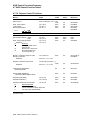
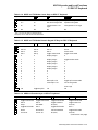
2.10.2
Terminal ID to Host . . . . . . . . . . . . . . . . . . . . . . . . . . . . . . . . . . . . . . .
2.10.3
VT Default Character Set . . . . . . . . . . . . . . . . . . . . . . . . . . . . . . . . . .
2.10.4
PCTerm Character Set . . . . . . . . . . . . . . . . . . . . . . . . . . . . . . . . . . . . .
2.10.5
7-Bit NRCS Characters . . . . . . . . . . . . . . . . . . . . . . . . . . . . . . . . . . . .
2.10.6
Transmit 7-Bit Controls . . . . . . . . . . . . . . . . . . . . . . . . . . . . . . . . . . . .
2.11
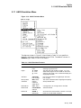
ASCII Emulation Menu . . . . . . . . . . . . . . . . . . . . . . . . . . . . . . . . . . . . . . .
2.12
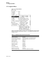
Keyboard Menu . . . . . . . . . . . . . . . . . . . . . . . . . . . . . . . . . . . . . . . . . . . . .
2.12.1
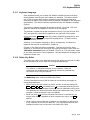
Keyboard Language . . . . . . . . . . . . . . . . . . . . . . . . . . . . . . . . . . . . . . .
2.12.2
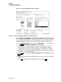
Define Key Editor . . . . . . . . . . . . . . . . . . . . . . . . . . . . . . . . . . . . . . . .
2.12.2.1
Copy of Key Default—Moving a Standard Function . . . . . . . . . . . .
2.12.2.2
Customization . . . . . . . . . . . . . . . . . . . . . . . . . . . . . . . . . . . . . . . .
2.12.2.3
Modifier Keys . . . . . . . . . . . . . . . . . . . . . . . . . . . . . . . . . . . . . . . . .
2.12.2.4
Creating a New Function . . . . . . . . . . . . . . . . . . . . . . . . . . . . . . . .
2.12.2.5
Examples of Creating New Functions . . . . . . . . . . . . . . . . . . . . . .
2.12.2.6
Correcting a Mistake . . . . . . . . . . . . . . . . . . . . . . . . . . . . . . . . . . .
2.12.2.7
Creating A New Alphanumeric Key or Keyboard Layout . . . . . . . .
2.12.2.8
Examples of Creating New Alphanumeric Keys . . . . . . . . . . . . . . .
2.12.2.9
User-Defined Keys . . . . . . . . . . . . . . . . . . . . . . . . . . . . . . . . . . . . .
2.12.2.10
Programming Notes . . . . . . . . . . . . . . . . . . . . . . . . . . . . . . . . . . . .
2.12.3
Save Key Definitions . . . . . . . . . . . . . . . . . . . . . . . . . . . . . . . . . . . . . .
2.12.4
Recall Key Definitions . . . . . . . . . . . . . . . . . . . . . . . . . . . . . . . . . . . . .
2.12.5
Lock Key Definitions . . . . . . . . . . . . . . . . . . . . . . . . . . . . . . . . . . . . . .
2.12.6
Caps Lock Function . . . . . . . . . . . . . . . . . . . . . . . . . . . . . . . . . . . . . . .
2.12.7
Keyclick, Warning Bell, and Margin Bell Volume . . . . . . . . . . . . . . . . .
2.12.7.1
Visible Bell . . . . . . . . . . . . . . . . . . . . . . . . . . . . . . . . . . . . . . . . . . .
2.12.8
Keyboard Encoding . . . . . . . . . . . . . . . . . . . . . . . . . . . . . . . . . . . . . . .
2.12.9
Auto Repeat . . . . . . . . . . . . . . . . . . . . . . . . . . . . . . . . . . . . . . . . . . . . .
2.12.10
Data Processing Keys . . . . . . . . . . . . . . . . . . . . . . . . . . . . . . . . . . . . . .
2.12.11
Application Cursor Keys . . . . . . . . . . . . . . . . . . . . . . . . . . . . . . . . . . .
2.12.12
Application Keypad Mode . . . . . . . . . . . . . . . . . . . . . . . . . . . . . . . . . .
2.12.13
Map PC Keyboard to VT . . . . . . . . . . . . . . . . . . . . . . . . . . . . . . . . . . .
2.12.14
Ignore Missing Keyboard . . . . . . . . . . . . . . . . . . . . . . . . . . . . . . . . . . .
2.13
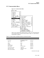
Communication Menu . . . . . . . . . . . . . . . . . . . . . . . . . . . . . . . . . . . . . . . .
2.13.1
Communication Port Select . . . . . . . . . . . . . . . . . . . . . . . . . . . . . . . . .
2.13.2
Word Size . . . . . . . . . . . . . . . . . . . . . . . . . . . . . . . . . . . . . . . . . . . . . . .
2.13.3
Parity . . . . . . . . . . . . . . . . . . . . . . . . . . . . . . . . . . . . . . . . . . . . . . . . . .
2.13.4
Stop Bits . . . . . . . . . . . . . . . . . . . . . . . . . . . . . . . . . . . . . . . . . . . . . . .
2.13.5
Transmit Speed . . . . . . . . . . . . . . . . . . . . . . . . . . . . . . . . . . . . . . . . . .
2.13.6
Receive Speed . . . . . . . . . . . . . . . . . . . . . . . . . . . . . . . . . . . . . . . . . . .
2.13.7
Transmit Flow Control . . . . . . . . . . . . . . . . . . . . . . . . . . . . . . . . . . . . .
2.13.8
Receive Flow Control . . . . . . . . . . . . . . . . . . . . . . . . . . . . . . . . . . . . . .
2.13.9
Flow Control Threshold . . . . . . . . . . . . . . . . . . . . . . . . . . . . . . . . . . . .
2.13.10
Transmit Rate Limit, Fkey Rate Limit . . . . . . . . . . . . . . . . . . . . . . . . .
2.13.11
Ignore Null Character . . . . . . . . . . . . . . . . . . . . . . . . . . . . . . . . . . . . .
2.13.12
Local Echo . . . . . . . . . . . . . . . . . . . . . . . . . . . . . . . . . . . . . . . . . . . . . .
2.13.13
Half Duplex . . . . . . . . . . . . . . . . . . . . . . . . . . . . . . . . . . . . . . . . . . . . .
2.13.14
Auto Answerback . . . . . . . . . . . . . . . . . . . . . . . . . . . . . . . . . . . . . . . . .
2.13.15
Answerback Message . . . . . . . . . . . . . . . . . . . . . . . . . . . . . . . . . . . . . .
2.13.16
Answerback Concealed . . . . . . . . . . . . . . . . . . . . . . . . . . . . . . . . . . . . .
2.14
Modem Menu . . . . . . . . . . . . . . . . . . . . . . . . . . . . . . . . . . . . . . . . . . . . . . .
2.14.1
Enable Modem Control . . . . . . . . . . . . . . . . . . . . . . . . . . . . . . . . . . . .
2.14.2
Disconnect Delay . . . . . . . . . . . . . . . . . . . . . . . . . . . . . . . . . . . . . . . . .
2.14.3
Modem High Speed . . . . . . . . . . . . . . . . . . . . . . . . . . . . . . . . . . . . . . .
2.14.4
Modem Low Speed . . . . . . . . . . . . . . . . . . . . . . . . . . . . . . . . . . . . . . . .
2–34
2–34
2–34
2–34
2–34
2–35
2–36
2–37
2–37
2–38
2–39
2–39
2–39
2–39
2–40
2–40
2–40
2–41
2–41
2–42
2–42
2–42
2–42
2–42
2–43
2–43
2–43
2–43
2–43
2–44
2–44
2–44
2–45
2–46
2–47
2–47
2–47
2–48
2–48
2–48
2–49
2–49
2–49
2–50
2–50
2–50
2–50
2–50
2–51
2–52
2–52
2–52
2–53
2–53
ix
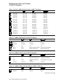
2.15
Printer Menu . . . . . . . . . . . . . . . . . . . . . . . . . . . . . . . . . . . . . . . . . . . . . . .
2.15.1
Port Select . . . . . . . . . . . . . . . . . . . . . . . . . . . . . . . . . . . . . . . . . . . . . .
2.15.2
Print Mode . . . . . . . . . . . . . . . . . . . . . . . . . . . . . . . . . . . . . . . . . . . . . .
2.15.3
Printer Type . . . . . . . . . . . . . . . . . . . . . . . . . . . . . . . . . . . . . . . . . . . . .
2.15.4
Printer Character Sets . . . . . . . . . . . . . . . . . . . . . . . . . . . . . . . . . . . . .
2.15.4.1
DEC/ISO Character Sets . . . . . . . . . . . . . . . . . . . . . . . . . . . . . . . .
2.15.4.2
PC Character Sets . . . . . . . . . . . . . . . . . . . . . . . . . . . . . . . . . . . . .
2.15.5
Print Extent . . . . . . . . . . . . . . . . . . . . . . . . . . . . . . . . . . . . . . . . . . . . .
2.15.6
Print Terminator . . . . . . . . . . . . . . . . . . . . . . . . . . . . . . . . . . . . . . . . .
2.15.7
Serial Print Speed . . . . . . . . . . . . . . . . . . . . . . . . . . . . . . . . . . . . . . . .
2.15.8
2-Way Communication . . . . . . . . . . . . . . . . . . . . . . . . . . . . . . . . . . . . .
2.15.9
Transmit Flow Control . . . . . . . . . . . . . . . . . . . . . . . . . . . . . . . . . . . . .
2.15.10
Receive Flow Control . . . . . . . . . . . . . . . . . . . . . . . . . . . . . . . . . . . . . .
2.15.11
Word Size . . . . . . . . . . . . . . . . . . . . . . . . . . . . . . . . . . . . . . . . . . . . . . .
2.15.12
Parity . . . . . . . . . . . . . . . . . . . . . . . . . . . . . . . . . . . . . . . . . . . . . . . . . .
2.15.13
Stop Bits . . . . . . . . . . . . . . . . . . . . . . . . . . . . . . . . . . . . . . . . . . . . . . .
2.15.14
Same as Receive . . . . . . . . . . . . . . . . . . . . . . . . . . . . . . . . . . . . . . . . . .
2.16
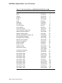
Tabs . . . . . . . . . . . . . . . . . . . . . . . . . . . . . . . . . . . . . . . . . . . . . . . . . . . . .
2.17
Sound . . . . . . . . . . . . . . . . . . . . . . . . . . . . . . . . . . . . . . . . . . . . . . . . . . . . .
2.18
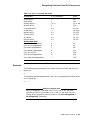
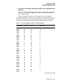
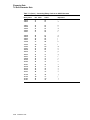
Set-Up Factory Defaults . . . . . . . . . . . . . . . . . . . . . . . . . . . . . . . . . . . . . . .
2–54
2–54
2–54
2–55
2–55
2–56
2–56
2–56
2–56
2–56
2–57
2–57
2–57
2–57
2–58
2–58
2–58
2–58
2–59
2–61
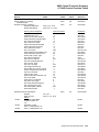
3 Desktop Features
3.1
3.2
3.3
3.4
3.5
3.6
3.6.1
3.6.2
3.7
Introduction . . . . . . . . . . . . . . . .
Invoking Desktop Features . . . .
Calculator . . . . . . . . . . . . . . . . .
Clock . . . . . . . . . . . . . . . . . . . . .
Review Previous Lines . . . . . . . .
Character Set Tables . . . . . . . . .
Show Character Sets feature
Banner message . . . . . . . . . .
Keyboard Summary . . . . . . . . . .
.
.
.
.
.
.
.
.
.
.
.
.
.
.
.
.
.
.
.
.
.
.
.
.
.
.
.
.
.
.
.
.
.
.
.
.
.
.
.
.
.
.
.
.
.
.
.
.
.
.
.
.
.
.
.
.
.
.
.
.
.
.
.
.
.
.
.
.
.
.
.
.
.
.
.
.
.
.
.
.
.
.
.
.
.
.
.
.
.
.
.
.
.
.
.
.
.
.
.
.
.
.
.
.
.
.
.
.
.
.
.
.
.
.
.
.
.
.
.
.
.
.
.
.
.
.
.
.
.
.
.
.
.
.
.
.
.
.
.
.
.
.
.
.
.
.
.
.
.
.
.
.
.
.
.
.
.
.
.
.
.
.
.
.
.
.
.
.
.
.
.
.
.
.
.
.
.
.
.
.
.
.
.
.
.
.
.
.
.
.
.
.
.
.
.
.
.
.
.
.
.
.
.
.
.
.
.
.
.
.
.
.
.
.
.
.
.
.
.
.
.
.
.
.
.
.
.
.
.
.
.
.
.
.
.
.
.
.
.
.
.
.
.
.
.
.
.
.
.
.
.
.
.
.
.
.
.
.
.
.
.
.
.
.
.
.
.
.
.
.
.
.
.
.
.
.
.
.
.
.
.
.
.
.
.
.
.
.
3–1
3–1
3–2
3–5
3–7
3–7
3–7
3–8
3–8
Introduction . . . . . . . . . . . . . . . . . . . . . . . . . . . . . . . .
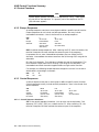
Control Characters . . . . . . . . . . . . . . . . . . . . . . . . . . .
Control Functions . . . . . . . . . . . . . . . . . . . . . . . . . . .
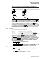
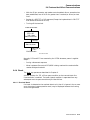
Sequence Format . . . . . . . . . . . . . . . . . . . . . . . . .
Escape Sequences . . . . . . . . . . . . . . . . . . . . . . . .
Control Sequences . . . . . . . . . . . . . . . . . . . . . . . .
Control Sequence Introducer . . . . . . . . . . . . .
Parameters . . . . . . . . . . . . . . . . . . . . . . . . . .
Intermediate Characters . . . . . . . . . . . . . . . .
Final Character . . . . . . . . . . . . . . . . . . . . . . .
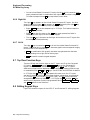
Device Control Strings . . . . . . . . . . . . . . . . . . . . .
Using Control Characters in Sequences . . . . . . . .
7-Bit Code Extension Technique . . . . . . . . . . . . . .
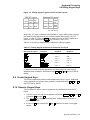
Working with 7-Bit and 8-Bit Environments . . . . . . .
Conventions for Codes Received by the Terminal .
Conventions for Codes Sent by the Terminal . . . .
Showing Control Characters . . . . . . . . . . . . . . . . . . .
.
.
.
.
.
.
.
.
.
.
.
.
.
.
.
.
.
.
.
.
.
.
.
.
.
.
.
.
.
.
.
.
.
.
.
.
.
.
.
.
.
.
.
.
.
.
.
.
.
.
.
.
.
.
.
.
.
.
.
.
.
.
.
.
.
.
.
.
.
.
.
.
.
.
.
.
.
.
.
.
.
.
.
.
.
.
.
.
.
.
.
.
.
.
.
.
.
.
.
.
.
.
.
.
.
.
.
.
.
.
.
.
.
.
.
.
.
.
.
.
.
.
.
.
.
.
.
.
.
.
.
.
.
.
.
.
.
.
.
.
.
.
.
.
.
.
.
.
.
.
.
.
.
.
.
.
.
.
.
.
.
.
.
.
.
.
.
.
.
.
.
.
.
.
.
.
.
.
.
.
.
.
.
.
.
.
.
.
.
.
.
.
.
.
.
.
.
.
.
.
.
.
.
.
.
.
.
.
.
.
.
.
.
.
.
.
.
.
.
.
.
.
.
.
.
.
.
.
.
.
.
.
.
.
.
.
.
.
.
.
.
.
.
.
.
.
.
.
.
.
.
.
.
.
.
.
.
.
.
.
.
.
.
.
.
.
.
.
.
.
.
.
4–1
4–1
4–5
4–5
4–6
4–6
4–6
4–7
4–8
4–8
4–8
4–9
4–9
4–10
4–10
4–10
4–11
Part II VT520 ANSI Mode
4 ANSI Control Functions Summary
4.1
4.2
4.3
4.3.1
4.3.2
4.3.3
4.3.3.1
4.3.3.2
4.3.3.3
4.3.3.4
4.3.4
4.3.5
4.3.6
4.4
4.4.1
4.4.2
4.5
x
4.6
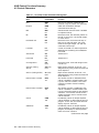
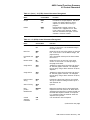
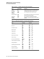
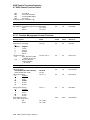
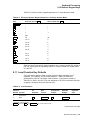
Terminal Management Functions . . . . . . . . . . . . . . . . . . . . . . . . .
4.7
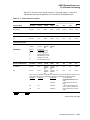
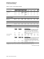
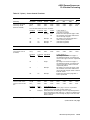
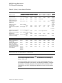
ANSI Control Function Tables . . . . . . . . . . . . . . . . . . . . . . . . . . .
4.7.1
Sessions Management Control Functions . . . . . . . . . . . . . . . .
4.7.2
Window Management Control Functions . . . . . . . . . . . . . . . .
4.7.3
Audible Attributes Control Functions . . . . . . . . . . . . . . . . . .
4.7.4
Color Selection Control Functions . . . . . . . . . . . . . . . . . . . . .
4.7.5
Visual Attributes Control Functions . . . . . . . . . . . . . . . . . . .
4.7.6
Editing Control Functions . . . . . . . . . . . . . . . . . . . . . . . . . . .
4.7.7
Text Processing Control Functions . . . . . . . . . . . . . . . . . . . . .
4.7.8
Graphic Character Sets Control Functions . . . . . . . . . . . . . . .
4.7.9
Keyboard Processing Control Functions . . . . . . . . . . . . . . . .
4.7.10
Printer Control Functions . . . . . . . . . . . . . . . . . . . . . . . . . . .
4.7.11
Terminal Management Control Functions . . . . . . . . . . . . . . .
4.7.12
Terminal Management—Communications Control Functions
4.7.13
Terminal Synchronization Control Functions . . . . . . . . . . . . .
4.7.14
Reports Control Functions . . . . . . . . . . . . . . . . . . . . . . . . . . .
4.8
VT52 Mode Escape Sequences . . . . . . . . . . . . . . . . . . . . . . . . . . .
.
.
.
.
.
.
.
.
.
.
.
.
.
.
.
.
.
.
.
.
.
.
.
.
.
.
.
.
.
.
.
.
.
.
.
.
.
.
.
.
.
.
.
.
.
.
.
.
.
.
.
.
.
.
.
.
.
.
.
.
.
.
.
.
.
.
.
.
.
.
.
.
.
.
.
.
.
.
.
.
.
.
.
.
.
.
.
.
.
.
.
.
.
.
.
.
.
.
.
.
.
.
.
.
.
.
.
.
.
.
.
.
.
.
.
.
.
.
.
4–15
4–16
4–16
4–17
4–18
4–18
4–20
4–21
4–22
4–25
4–27
4–33
4–34
4–39
4–41
4–42
4–45
.
.
.
.
.
.
.
.
.
.
.
.
.
.
.
.
.
.
.
.
.
.
.
.
.
.
.
.
.
.
.
.
.
.
.
.
.
.
.
.
.
.
.
.
.
.
.
.
.
.
.
.
.
.
.
.
.
.
.
.
.
.
.
.
.
.
.
.
.
.
.
.
.
.
.
.
.
.
.
.
.
.
.
.
.
.
.
.
.
.
.
.
.
.
.
.
.
.
.
.
.
.
.
.
.
.
.
.
.
.
.
.
.
.
.
.
.
.
.
.
.
.
.
.
.
.
.
.
.
.
.
.
.
.
.
.
.
.
.
.
.
.
.
.
.
.
.
.
.
.
.
.
.
.
.
.
.
.
.
.
.
.
.
.
.
.
.
.
.
.
.
.
.
.
.
.
.
.
.
.
.
.
.
.
.
.
.
.
.
.
.
.
.
.
.
.
.
.
.
.
.
.
.
.
.
.
.
.
.
.
5–1
5–3
5–3
5–4
5–4
5–5
5–5
5–6
5–7
5–7
5–7
5–8
5–8
5–9
5–11
5–12
5–13
5–14
5–15
5–16
5–17
5–18
5–19
5–19
5–20
5–21
5–22
5–23
5–23
5–24
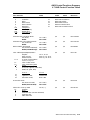
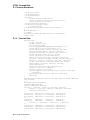
5 ANSI Control Functions
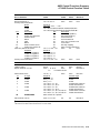
ANSI Conformance Levels . . . . . . . . . . . . . . . . . . . . . . . . . . . .
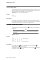
CBT—Cursor Backward Tabulation . . . . . . . . . . . . . . . . . . . . .
CHA—Cursor Horizontal Absolute . . . . . . . . . . . . . . . . . . . . . .
CHT—Cursor Horizontal Forward Tabulation . . . . . . . . . . . . .
CNL—Cursor Next Line . . . . . . . . . . . . . . . . . . . . . . . . . . . . . .
CPL—Cursor Previous Line . . . . . . . . . . . . . . . . . . . . . . . . . . .
CPR—Cursor Position Report . . . . . . . . . . . . . . . . . . . . . . . . .
CRM—Show Control Character Mode . . . . . . . . . . . . . . . . . . .
CUB—Cursor Backward . . . . . . . . . . . . . . . . . . . . . . . . . . . . .
CUD—Cursor Down . . . . . . . . . . . . . . . . . . . . . . . . . . . . . . . . .
CUF—Cursor Forward . . . . . . . . . . . . . . . . . . . . . . . . . . . . . . .
CUP—Cursor Position . . . . . . . . . . . . . . . . . . . . . . . . . . . . . . .
CUU—Cursor Up . . . . . . . . . . . . . . . . . . . . . . . . . . . . . . . . . . .
DA1—Primary Device Attributes . . . . . . . . . . . . . . . . . . . . . . .
DA2—Secondary Device Attributes . . . . . . . . . . . . . . . . . . . . .
DA3—Tertiary Device Attributes . . . . . . . . . . . . . . . . . . . . . . .
DCH—Delete Character . . . . . . . . . . . . . . . . . . . . . . . . . . . . . .
DDD1, DDD2, DDD3 . . . . . . . . . . . . . . . . . . . . . . . . . . . . . . . .
DECAAM—Set/Reset Auto Answerback Mode . . . . . . . . . . . . .
DECAC—Assign Color . . . . . . . . . . . . . . . . . . . . . . . . . . . . . .
DECALN—Screen Alignment Pattern . . . . . . . . . . . . . . . . . . .
DECANM—ANSI Mode . . . . . . . . . . . . . . . . . . . . . . . . . . . . . .
DECANM Exit—Exiting ANSI (VT52) Mode . . . . . . . . . . . . . .
DECARM—Autorepeat Mode . . . . . . . . . . . . . . . . . . . . . . . . . .
DECARR—Select Auto Repeat Rate . . . . . . . . . . . . . . . . . . . .
DECARSM—Set/Reset Auto Resize Mode . . . . . . . . . . . . . . . .
DECATC—Alternate Text Color . . . . . . . . . . . . . . . . . . . . . . .
DECATCBM—Set/Reset Alternate Text Color Blink Mode . . . .
DECATCUM—Set/Reset Alternate Text Color Underline Mode
DECAUPSS—Assigning User-Preferred Supplemental Sets . .
.
.
.
.
.
.
.
.
.
.
.
.
.
.
.
.
.
.
.
.
.
.
.
.
.
.
.
.
.
.
.
.
.
.
.
.
.
.
.
.
.
.
.
.
.
.
.
.
.
.
.
.
.
.
.
.
.
.
.
.
xi
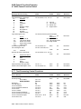
DECAWM—Autowrap Mode . . . . . . . . . . . . . . . . . . . . . . . . . . . . .
DECBBSM—Bold and Blink Style Mode . . . . . . . . . . . . . . . . . . .
DECBI—Back Index . . . . . . . . . . . . . . . . . . . . . . . . . . . . . . . . . . .
DECBKM—Backarrow Key Mode . . . . . . . . . . . . . . . . . . . . . . . . .
DECCANSM—Conceal Answerback Message Mode . . . . . . . . . . .
DECCAPSLK—Caps Lock Mode . . . . . . . . . . . . . . . . . . . . . . . . . .
DECCARA—Change Attributes in Rectangular Area . . . . . . . . . .
DECCIR—Cursor Information Report (Terminal to Host) . . . . . . .
DECCKD—Copy Key Default . . . . . . . . . . . . . . . . . . . . . . . . . . . . .
DECCKM—Cursor Keys Mode . . . . . . . . . . . . . . . . . . . . . . . . . . . .
DECCKSR—Memory Checksum Report . . . . . . . . . . . . . . . . . . . . .
DECCOLM—Selecting 80 or 132 Columns per Page . . . . . . . . . . .
DECCRA—Copy Rectangular Area . . . . . . . . . . . . . . . . . . . . . . . .
DECCRTST—CRT Saver Timing . . . . . . . . . . . . . . . . . . . . . . . . .
DECCRTSM—Set/Reset CRT Save Mode . . . . . . . . . . . . . . . . . . . .
DECDC—Delete Column . . . . . . . . . . . . . . . . . . . . . . . . . . . . . . . .
DECDHL—Double-Width, Double-Height Line . . . . . . . . . . . . . . .
DECDLD—Dynamically Redefinable Character Sets Extension . . .
DECDMAC—Define Macro . . . . . . . . . . . . . . . . . . . . . . . . . . . . . .
DECDLDA—Down Line Load Allocation . . . . . . . . . . . . . . . . . . .
DECDWL—Double-Width, Single-Height Line . . . . . . . . . . . . . . .
DECECM—Erase Color Mode . . . . . . . . . . . . . . . . . . . . . . . . . . . .
DECEKBD—Extended Keyboard Report . . . . . . . . . . . . . . . . . . .
DECELF—Enable Local Functions . . . . . . . . . . . . . . . . . . . . . . . .
DECERA—Erase Rectangular Area . . . . . . . . . . . . . . . . . . . . . . .
DECES—Enable Session . . . . . . . . . . . . . . . . . . . . . . . . . . . . . . . .
DECESKM—Enable Secondary Keyboard Language Mode . . . . . .
DECFI—Forward Index . . . . . . . . . . . . . . . . . . . . . . . . . . . . . . . . .
DECFRA—Fill Rectangular Area . . . . . . . . . . . . . . . . . . . . . . . . . .
DECFWM—Set/Reset Framed Windows Mode . . . . . . . . . . . . . . . .
DECHDPXM—Set/Reset Half-Duplex Mode . . . . . . . . . . . . . . . . .
DECHEM—Hebrew Encoding Mode . . . . . . . . . . . . . . . . . . . . . . .
DECHEBM—Hebrew/N-A Keyboard Mapping Mode . . . . . . . . . . .
DECHWUM—Host Wake-Up Mode (CRT and Energy Saver) . . . .
DECIC—Insert Column . . . . . . . . . . . . . . . . . . . . . . . . . . . . . . . . .
DECID—Identify Device . . . . . . . . . . . . . . . . . . . . . . . . . . . . . . . .
DECINVM—Invoke Macro . . . . . . . . . . . . . . . . . . . . . . . . . . . . . . .
DECIPEM—Enter/Return from IBM ProPrinter Emulation Mode .
DECKBD—Keyboard Language Selection . . . . . . . . . . . . . . . . . . .
DECKBUM—Typewriter or Data Processing Keys . . . . . . . . . . . .
DECKLHIM—Keyboard LED’s Host Indicator Mode . . . . . . . . . . .
DECKPAM—Keypad Application Modes . . . . . . . . . . . . . . . . . . . .
DECKPM—Key Position Mode . . . . . . . . . . . . . . . . . . . . . . . . . . . .
DECKPNM—Keypad Numeric Modes . . . . . . . . . . . . . . . . . . . . . .
DECLANS—Load Answerback Message . . . . . . . . . . . . . . . . . . . .
DECLBAN—Load Banner Message . . . . . . . . . . . . . . . . . . . . . . . .
DECLFKC—Local Function Key Control . . . . . . . . . . . . . . . . . . .
xii
.
.
.
.
.
.
.
.
.
.
.
.
.
.
.
.
.
.
.
.
.
.
.
.
.
.
.
.
.
.
.
.
.
.
.
.
.
.
.
.
.
.
.
.
.
.
.
.
.
.
.
.
.
.
.
.
.
.
.
.
.
.
.
.
.
.
.
.
.
.
.
.
.
.
.
.
.
.
.
.
.
.
.
.
.
.
.
.
.
.
.
.
.
.
.
.
.
.
.
.
.
.
.
.
.
.
.
.
.
.
.
.
.
.
.
.
.
.
.
.
.
.
.
.
.
.
.
.
.
.
.
.
.
.
.
.
.
.
.
.
.
.
.
.
.
.
.
.
.
.
.
.
.
.
.
.
.
.
.
.
.
.
.
.
.
.
.
.
.
.
.
.
.
.
.
.
.
.
.
.
.
.
.
.
.
.
.
.
.
.
.
.
.
.
.
.
.
.
.
.
.
.
.
.
.
.
.
.
.
.
.
.
.
.
.
.
.
.
.
.
.
.
.
.
.
.
.
.
.
.
.
.
.
.
.
.
.
.
.
.
.
.
.
.
.
.
.
.
.
.
.
.
.
.
.
.
.
.
.
.
.
.
.
.
.
.
.
.
.
.
.
.
.
.
.
.
.
.
.
.
.
.
5–25
5–25
5–26
5–26
5–27
5–28
5–28
5–30
5–31
5–32
5–33
5–34
5–35
5–36
5–37
5–37
5–38
5–39
5–45
5–47
5–48
5–48
5–49
5–51
5–52
5–53
5–53
5–54
5–55
5–56
5–56
5–57
5–58
5–59
5–59
5–60
5–61
5–62
5–63
5–65
5–65
5–66
5–66
5–67
5–68
5–69
5–70
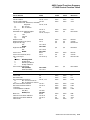
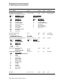
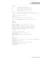
DECLL—Load LEDs . . . . . . . . . . . . . . . . . . . . . . . . . . . . . .
DECLRMM—Left Right Margin Mode . . . . . . . . . . . . . . . . .
DECLTOD—Load Time of Day . . . . . . . . . . . . . . . . . . . . . .
DECMCM—Modem Control Mode . . . . . . . . . . . . . . . . . . . .
DECMSR—Macro Space Report . . . . . . . . . . . . . . . . . . . . . .
DECNAKB—Greek/N-A Keyboard Mapping Mode . . . . . . . .
DECNCSM—No Clearing Screen On Column Change Mode
DECNKM—Numeric Keypad Mode . . . . . . . . . . . . . . . . . . .
DECNRCM—National Replacement Character Set Mode . .
DECNULM—Null Mode . . . . . . . . . . . . . . . . . . . . . . . . . . . .
DECNUMLK—Num Lock Mode . . . . . . . . . . . . . . . . . . . . . .
DECOM—Origin Mode . . . . . . . . . . . . . . . . . . . . . . . . . . . . .
DECOSCNM—Set/Reset Overscan Mode (VT520 only) . . . .
DECPAK—Program Alphanumeric Key . . . . . . . . . . . . . . . .
DECPCCM—Page Cursor-Coupling Mode . . . . . . . . . . . . . .
DECPCTERM—Enter/Exit PCTerm or Scancode Mode . . . .
DECPEX—Print Extent Mode . . . . . . . . . . . . . . . . . . . . . . .
DECPFF—Print Form Feed Mode . . . . . . . . . . . . . . . . . . . .
DECPFK—Program Function Key . . . . . . . . . . . . . . . . . . . .
DECPKA—Program Key Action . . . . . . . . . . . . . . . . . . . . . .
DECPKFMR—Program Key Free Memory Report . . . . . . .
DECPS—Play Sound . . . . . . . . . . . . . . . . . . . . . . . . . . . . . .
DECRARA—Reverse Attributes in Rectangular Area . . . . .
DECRC—Restore Cursor . . . . . . . . . . . . . . . . . . . . . . . . . . .
DECRLCM—Right-to-Left Copy Mode . . . . . . . . . . . . . . . . .
DECRLM—Right-to-Left Mode . . . . . . . . . . . . . . . . . . . . . .
DECRPAK—Report All Modifiers/Alphanumeric Key State .
DECRPDE—Report Displayed Extent . . . . . . . . . . . . . . . . .
DECRPFK - Report Function Key Definition . . . . . . . . . . . .
DECRPKT—Report Key Type . . . . . . . . . . . . . . . . . . . . . . .
DECRPL—Review Previous Lines Mode . . . . . . . . . . . . . . .
DECRPM—Report Mode - Terminal To Host . . . . . . . . . . . .
DECRPSS—Report Selection or Setting . . . . . . . . . . . . . . . .
DECRPTUI—Report Terminal Unit ID . . . . . . . . . . . . . . . .
DECRQCRA—Request Checksum of Rectangular Area . . . .
DECRQDE—Request Displayed Extent . . . . . . . . . . . . . . . .
DECRQKD—Request Key Definition . . . . . . . . . . . . . . . . . .
DECRQKT—Request Key Type . . . . . . . . . . . . . . . . . . . . . .
DECRQM—Request Mode - Host To Terminal . . . . . . . . . . .
DECRQPKFM—Request Program Key Free Memory . . . . .
DECRQPSR—Request Presentation State Report . . . . . . . .
DECRQSS—Request Selection or Setting . . . . . . . . . . . . . .
DECRQTSR—Request Terminal State Report . . . . . . . . . .
DECCTR—Color Table Request . . . . . . . . . . . . . . . . . . . . . .
DECRQUPSS—Request User-Preferred Supplemental Set .
DECRSPS—Restore Presentation State . . . . . . . . . . . . . . .
DECRSTS—Restore Terminal State . . . . . . . . . . . . . . . . . .
.
.
.
.
.
.
.
.
.
.
.
.
.
.
.
.
.
.
.
.
.
.
.
.
.
.
.
.
.
.
.
.
.
.
.
.
.
.
.
.
.
.
.
.
.
.
.
.
.
.
.
.
.
.
.
.
.
.
.
.
.
.
.
.
.
.
.
.
.
.
.
.
.
.
.
.
.
.
.
.
.
.
.
.
.
.
.
.
.
.
.
.
.
.
.
.
.
.
.
.
.
.
.
.
.
.
.
.
.
.
.
.
.
.
.
.
.
.
.
.
.
.
.
.
.
.
.
.
.
.
.
.
.
.
.
.
.
.
.
.
.
.
.
.
.
.
.
.
.
.
.
.
.
.
.
.
.
.
.
.
.
.
.
.
.
.
.
.
.
.
.
.
.
.
.
.
.
.
.
.
.
.
.
.
.
.
.
.
.
.
.
.
.
.
.
.
.
.
.
.
.
.
.
.
.
.
.
.
.
.
.
.
.
.
.
.
.
.
.
.
.
.
.
.
.
.
.
.
.
.
.
.
.
.
.
.
.
.
.
.
.
.
.
.
.
.
.
.
.
.
.
.
.
.
.
.
.
.
.
.
.
.
.
.
.
.
.
.
.
.
.
.
.
.
.
.
.
.
.
.
.
.
.
.
.
.
.
.
.
.
.
.
.
.
.
.
.
.
.
.
.
.
.
.
.
.
.
.
.
.
.
.
.
.
.
.
.
.
.
.
.
.
.
.
.
.
.
.
.
.
.
.
.
.
.
.
.
.
.
.
.
.
.
.
.
.
.
.
.
.
.
.
.
.
.
.
.
.
.
.
.
.
.
.
.
.
.
.
.
.
.
.
.
.
.
.
.
.
.
.
.
.
.
.
.
.
.
.
.
.
.
.
.
.
.
.
.
.
.
.
.
.
.
.
.
.
.
.
.
.
.
.
.
.
.
.
.
.
.
.
.
.
.
.
.
.
.
.
.
.
.
.
.
.
.
.
.
.
.
.
.
.
.
.
.
.
.
.
.
.
.
.
.
.
.
.
.
.
.
.
.
.
.
.
.
.
.
.
.
.
.
.
.
.
.
.
.
.
.
.
.
.
.
.
.
.
.
.
.
.
.
.
.
.
.
.
.
.
.
.
.
.
.
.
.
.
.
.
.
.
.
.
.
.
.
.
.
5–71
5–72
5–72
5–73
5–73
5–74
5–74
5–75
5–75
5–76
5–76
5–77
5–77
5–78
5–80
5–81
5–83
5–83
5–84
5–87
5–88
5–89
5–90
5–92
5–92
5–93
5–94
5–95
5–96
5–96
5–97
5–98
5–102
5–104
5–105
5–105
5–106
5–107
5–108
5–111
5–111
5–112
5–113
5–114
5–115
5–116
5–117
xiii
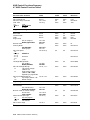
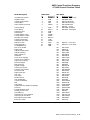
DECRSTS—Restore Terminal Color Table State .
DECSACE—Select Attribute Change Extent . . .
DECSASD—Select Active Status Display . . . . . .
DECSC—Save Cursor . . . . . . . . . . . . . . . . . . . . .
DECSCA—Select Character Protection Attribute
DECSCL—Select Conformance Level . . . . . . . . . .
DECSCLM—Scrolling Mode . . . . . . . . . . . . . . . .
DECSCNM—Screen Mode: Light or Dark Screen
DECSCP—Select Communication Port . . . . . . . .
DECSCPP—Select Columns Per Page . . . . . . . .
DECSCS—Select Communication Speed . . . . . . .
DECSCUSR—Set Cursor Style . . . . . . . . . . . . . .
DECSDDT—Select Disconnect Delay Time . . . . .
DECSDPT—Select Digital Printed Data Type . . .
DECSED—Selective Erase in Display . . . . . . . . .
DECSEST—Energy Saver Timing . . . . . . . . . . . .
DECSEL—Selective Erase in Line . . . . . . . . . . . .
DECSERA—Selective Erase Rectangular Area . .
DECSFC—Select Flow Control . . . . . . . . . . . . . .
DECSIN—Set Icon Name . . . . . . . . . . . . . . . . . .
DECSKCV—Set Key Click Volume . . . . . . . . . . .
DECSLCK—Set Lock Key Style . . . . . . . . . . . . . .
DECSLPP—Set Lines Per Page . . . . . . . . . . . . .
DECSLRM—Set Left and Right Margins . . . . . .
DECSMBV—Set Margin Bell Volume . . . . . . . . .
DECSMKR—Select Modifier Key Reporting . . . .
DECSNLS—Set Number of Lines Per Screen . . .
DECSPMA—Session Page Memory Allocation . .
DECSPP—Set Port Parameters . . . . . . . . . . . . . .
DECSPPCS—Select ProPrinter Character Set . .
DECSPRTT—Select Printer Type . . . . . . . . . . . .
DECSR—Secure Reset . . . . . . . . . . . . . . . . . . . . .
DECSRC—Secure Reset Confirmation . . . . . . . . .
DECSSCLS—Set Scroll Speed . . . . . . . . . . . . . .
DECSSDT—Select Status Display (Line) Type . .
DECSSL—Select Set-Up Language . . . . . . . . . . .
DECST8C—Set Tab at Every 8 Columns . . . . . .
DECSTBM—Set Top and Bottom Margins . . . . .
DECSTR—Soft Terminal Reset . . . . . . . . . . . . . .
DECSTGLT—Select Color Look-Up Table . . . . . .
DECSTRL—Set Transmit Rate Limit . . . . . . . . .
DECSTUI—Setting Terminal Unit ID . . . . . . . . .
DECSWBV—Set Warning Bell Volume . . . . . . . .
DECSWL—Single-Width, Single-Height Line . . .
DECSZS—Select Zero Symbol . . . . . . . . . . . . . . .
DECSWT—Set Window Title . . . . . . . . . . . . . . .
DECTABSR—Tab Stop Report . . . . . . . . . . . . . .
xiv
.
.
.
.
.
.
.
.
.
.
.
.
.
.
.
.
.
.
.
.
.
.
.
.
.
.
.
.
.
.
.
.
.
.
.
.
.
.
.
.
.
.
.
.
.
.
.
.
.
.
.
.
.
.
.
.
.
.
.
.
.
.
.
.
.
.
.
.
.
.
.
.
.
.
.
.
.
.
.
.
.
.
.
.
.
.
.
.
.
.
.
.
.
.
.
.
.
.
.
.
.
.
.
.
.
.
.
.
.
.
.
.
.
.
.
.
.
.
.
.
.
.
.
.
.
.
.
.
.
.
.
.
.
.
.
.
.
.
.
.
.
.
.
.
.
.
.
.
.
.
.
.
.
.
.
.
.
.
.
.
.
.
.
.
.
.
.
.
.
.
.
.
.
.
.
.
.
.
.
.
.
.
.
.
.
.
.
.
.
.
.
.
.
.
.
.
.
.
.
.
.
.
.
.
.
.
.
.
.
.
.
.
.
.
.
.
.
.
.
.
.
.
.
.
.
.
.
.
.
.
.
.
.
.
.
.
.
.
.
.
.
.
.
.
.
.
.
.
.
.
.
.
.
.
.
.
.
.
.
.
.
.
.
.
.
.
.
.
.
.
.
.
.
.
.
.
.
.
.
.
.
.
.
.
.
.
.
.
.
.
.
.
.
.
.
.
.
.
.
.
.
.
.
.
.
.
.
.
.
.
.
.
.
.
.
.
.
.
.
.
.
.
.
.
.
.
.
.
.
.
.
.
.
.
.
.
.
.
.
.
.
.
.
.
.
.
.
.
.
.
.
.
.
.
.
.
.
.
.
.
.
.
.
.
.
.
.
.
.
.
.
.
.
.
.
.
.
.
.
.
.
.
.
.
.
.
.
.
.
.
.
.
.
.
.
.
.
.
.
.
.
.
.
.
.
.
.
.
.
.
.
.
.
.
.
.
.
.
.
.
.
.
.
.
.
.
.
.
.
.
.
.
.
.
.
.
.
.
.
.
.
.
.
.
.
.
.
.
.
.
.
.
.
.
.
.
.
.
.
.
.
.
.
.
.
.
.
.
.
.
.
.
.
.
.
.
.
.
.
.
.
.
.
.
.
.
.
.
.
.
.
.
.
.
.
.
.
.
.
.
.
.
.
.
.
.
.
.
.
.
.
.
.
.
.
.
.
.
.
.
.
.
.
.
.
.
.
.
.
.
.
.
.
.
.
.
.
.
.
.
.
.
.
.
.
.
.
.
.
.
.
.
.
.
.
.
.
.
.
.
.
.
.
.
.
.
.
.
.
.
.
.
.
.
.
.
.
.
.
.
.
.
.
.
.
.
.
.
.
.
.
.
.
.
.
.
.
.
.
.
.
.
.
.
.
.
.
.
.
.
.
.
.
.
.
.
.
.
.
.
.
.
.
.
.
.
.
.
.
.
.
.
.
.
.
.
.
.
.
.
.
.
.
.
.
.
.
.
.
.
.
.
.
.
.
.
.
.
.
.
.
.
.
.
.
.
.
.
.
.
.
.
.
.
.
.
.
.
.
.
.
.
.
.
.
.
.
.
.
.
.
.
.
.
.
.
.
.
.
.
.
.
.
.
.
.
.
.
.
.
.
.
.
.
.
.
.
.
.
.
.
.
.
.
.
.
.
.
.
.
.
.
.
.
.
.
.
.
.
.
.
.
.
.
.
.
.
.
.
.
.
.
.
.
.
.
.
.
.
.
.
.
.
.
.
.
.
.
.
.
.
.
.
.
.
.
.
.
.
.
.
.
.
.
.
.
.
.
.
.
.
.
.
.
.
.
.
.
.
.
.
.
.
.
.
.
.
.
.
.
.
.
.
.
.
.
.
.
.
.
.
.
.
.
.
.
.
.
.
.
.
.
.
.
.
.
.
.
.
.
.
.
.
.
.
.
.
.
.
.
.
.
.
.
.
.
.
.
.
.
.
.
.
.
.
.
.
.
.
.
.
.
.
.
.
.
.
.
.
.
.
.
.
.
.
.
.
.
.
.
.
.
.
5–118
5–119
5–120
5–120
5–121
5–122
5–123
5–123
5–124
5–125
5–126
5–127
5–128
5–129
5–129
5–130
5–131
5–132
5–133
5–134
5–135
5–135
5–136
5–137
5–138
5–139
5–140
5–141
5–142
5–143
5–144
5–144
5–146
5–146
5–147
5–148
5–149
5–149
5–150
5–151
5–152
5–153
5–154
5–154
5–155
5–156
5–157
DECTCEM—Text Cursor Enable Mode . . . . . . . . . . . . . . . . . .
DECTID—Select Terminal ID . . . . . . . . . . . . . . . . . . . . . . . . .
DECTME—Terminal Mode Emulation . . . . . . . . . . . . . . . . . . .
DECTSR—Terminal State Report—Terminal to Host . . . . . . .
DECTSR—Terminal State Report (Color Table Report) . . . . . .
DECTST—Invoke Confidence Test . . . . . . . . . . . . . . . . . . . . . .
DECUDK—User Defined Keys . . . . . . . . . . . . . . . . . . . . . . . . .
DECUS—Update Session . . . . . . . . . . . . . . . . . . . . . . . . . . . . .
DECVCCM—Vertical Cursor-Coupling Mode . . . . . . . . . . . . . .
DECXCPR—Extended Cursor Position Report . . . . . . . . . . . . .
DECXRLM—Transmit Rate Limiting . . . . . . . . . . . . . . . . . . .
DL—Delete Line . . . . . . . . . . . . . . . . . . . . . . . . . . . . . . . . . . .
DSR—Device Status Reports . . . . . . . . . . . . . . . . . . . . . . . . .
DSR—Cursor Position Report (CPR) . . . . . . . . . . . . . . . . . . . .
DSR—Data Integrity Report . . . . . . . . . . . . . . . . . . . . . . . . . .
DSR—Extended Cursor Position Report (DECXCPR response)
DSR—Keyboard Report . . . . . . . . . . . . . . . . . . . . . . . . . . . . . .
DSR—Macro Space Report . . . . . . . . . . . . . . . . . . . . . . . . . . . .
DSR—Memory Checksum Report (DECCKSR) . . . . . . . . . . . .
DSR—Operating Status Report . . . . . . . . . . . . . . . . . . . . . . .
DSR—Printer Port Report . . . . . . . . . . . . . . . . . . . . . . . . . . .
DSR—User-Defined Keys Report (VT Level 4 or higher) . . . . .
ECH—Erase Character . . . . . . . . . . . . . . . . . . . . . . . . . . . . . .
ED—Erase in Display . . . . . . . . . . . . . . . . . . . . . . . . . . . . . . .
EL—Erase in Line . . . . . . . . . . . . . . . . . . . . . . . . . . . . . . . . . .
HPA—Horizontal Position Absolute . . . . . . . . . . . . . . . . . . . . .
HPR—Horizontal Position Relative . . . . . . . . . . . . . . . . . . . . .
HT—Horizontal Tab . . . . . . . . . . . . . . . . . . . . . . . . . . . . . . . . .
HTS—Horizontal Tab Set . . . . . . . . . . . . . . . . . . . . . . . . . . . . .
HVP—Horizontal and Vertical Position . . . . . . . . . . . . . . . . . .
ICH—Insert Character . . . . . . . . . . . . . . . . . . . . . . . . . . . . . . .
IL—Insert Line . . . . . . . . . . . . . . . . . . . . . . . . . . . . . . . . . . . .
IND—Index . . . . . . . . . . . . . . . . . . . . . . . . . . . . . . . . . . . . . . .
IRM—Insert/Replace Mode . . . . . . . . . . . . . . . . . . . . . . . . . . .
KAM—Keyboard Action Mode . . . . . . . . . . . . . . . . . . . . . . . . .
LNM—Line Feed/New Line Mode . . . . . . . . . . . . . . . . . . . . . .
LS—Locking Shift . . . . . . . . . . . . . . . . . . . . . . . . . . . . . . . . . .
MC—Media Copy . . . . . . . . . . . . . . . . . . . . . . . . . . . . . . . . . .
NEL—Next Line . . . . . . . . . . . . . . . . . . . . . . . . . . . . . . . . . . .
NP—Next Page . . . . . . . . . . . . . . . . . . . . . . . . . . . . . . . . . . . .
PP—Preceding Page . . . . . . . . . . . . . . . . . . . . . . . . . . . . . . . . .
PPA—Page Position Absolute . . . . . . . . . . . . . . . . . . . . . . . . .
PPB—Page Position Backward . . . . . . . . . . . . . . . . . . . . . . . .
PPR—Page Position Relative . . . . . . . . . . . . . . . . . . . . . . . . .
RIS—Reset to Initial State . . . . . . . . . . . . . . . . . . . . . . . . . . .
RM—Reset Mode . . . . . . . . . . . . . . . . . . . . . . . . . . . . . . . . . . .
S7C1T—Send C1 Control Character to the Host . . . . . . . . . . .
.
.
.
.
.
.
.
.
.
.
.
.
.
.
.
.
.
.
.
.
.
.
.
.
.
.
.
.
.
.
.
.
.
.
.
.
.
.
.
.
.
.
.
.
.
.
.
.
.
.
.
.
.
.
.
.
.
.
.
.
.
.
.
.
.
.
.
.
.
.
.
.
.
.
.
.
.
.
.
.
.
.
.
.
.
.
.
.
.
.
.
.
.
.
.
.
.
.
.
.
.
.
.
.
.
.
.
.
.
.
.
.
.
.
.
.
.
.
.
.
.
.
.
.
.
.
.
.
.
.
.
.
.
.
.
.
.
.
.
.
.
.
.
.
.
.
.
.
.
.
.
.
.
.
.
.
.
.
.
.
.
.
.
.
.
.
.
.
.
.
.
.
.
.
.
.
.
.
.
.
.
.
.
.
.
.
.
.
.
.
.
.
.
.
.
.
.
.
.
.
.
.
.
.
.
.
.
.
.
.
.
.
.
.
.
.
.
.
.
.
.
.
.
.
.
.
.
.
.
.
.
.
.
.
.
.
.
.
.
.
.
.
.
.
.
.
.
.
.
.
.
.
.
.
.
.
.
.
.
.
.
.
.
.
.
.
.
.
.
.
.
.
.
.
.
.
.
.
.
.
.
.
.
.
.
.
.
.
.
.
.
.
.
.
.
.
.
.
.
.
.
.
.
.
.
.
.
.
.
.
.
.
.
.
.
.
.
.
.
.
.
.
.
.
.
.
.
.
.
.
.
.
.
.
.
.
.
.
.
.
.
.
.
.
.
.
.
.
.
.
.
.
.
.
.
.
.
.
.
.
.
.
.
.
.
.
.
.
.
.
.
.
.
.
.
.
.
.
.
.
.
.
.
.
.
.
.
.
.
.
.
.
.
.
.
.
.
.
.
.
.
.
.
.
.
.
.
.
.
.
.
.
.
.
.
.
.
.
.
.
.
.
.
5–157
5–158
5–159
5–160
5–161
5–162
5–163
5–169
5–170
5–170
5–171
5–172
5–173
5–173
5–174
5–174
5–175
5–176
5–177
5–177
5–178
5–179
5–179
5–180
5–180
5–181
5–181
5–182
5–182
5–183
5–183
5–184
5–184
5–185
5–185
5–186
5–187
5–188
5–191
5–191
5–192
5–192
5–193
5–193
5–194
5–195
5–196
xv
S8C1T—Send C1 Control Character to the Host
SCS—Select Character Set . . . . . . . . . . . . . . . .
Designating Character Sets (SCS Sequences) . .
SD—Pan Up . . . . . . . . . . . . . . . . . . . . . . . . . . . .
SGR—Select Graphic Rendition . . . . . . . . . . . . .
SRM—Local Echo: Send/Receive Mode . . . . . . .
SS—Single Shifts . . . . . . . . . . . . . . . . . . . . . . . .
SM—Set Mode . . . . . . . . . . . . . . . . . . . . . . . . . .
SU—Pan Down . . . . . . . . . . . . . . . . . . . . . . . . .
TBC—Tab Clear . . . . . . . . . . . . . . . . . . . . . . . . .
VPA—Vertical Line Position Absolute . . . . . . . .
VPR—Vertical Position Relative . . . . . . . . . . . . .
.
.
.
.
.
.
.
.
.
.
.
.
.
.
.
.
.
.
.
.
.
.
.
.
.
.
.
.
.
.
.
.
.
.
.
.
.
.
.
.
.
.
.
.
.
.
.
.
.
.
.
.
.
.
.
.
.
.
.
.
.
.
.
.
.
.
.
.
.
.
.
.
.
.
.
.
.
.
.
.
.
.
.
.
.
.
.
.
.
.
.
.
.
.
.
.
.
.
.
.
.
.
.
.
.
.
.
.
.
.
.
.
.
.
.
.
.
.
.
.
.
.
.
.
.
.
.
.
.
.
.
.
.
.
.
.
.
.
.
.
.
.
.
.
.
.
.
.
.
.
.
.
.
.
.
.
.
.
.
.
.
.
.
.
.
.
.
.
.
.
.
.
.
.
.
.
.
.
.
.
.
.
.
.
.
.
.
.
.
.
.
.
.
.
.
.
.
.
.
.
.
.
.
.
.
.
.
.
.
.
.
.
.
.
.
.
.
.
.
.
.
.
.
.
.
.
.
.
.
.
.
.
.
.
.
.
.
.
.
.
5–196
5–197
5–197
5–200
5–201
5–204
5–205
5–206
5–207
5–207
5–208
5–208
.....
.....
Mode
.....
.....
.....
.....
.....
.....
.....
.
.
.
.
.
.
.
.
.
.
.
.
.
.
.
.
.
.
.
.
.
.
.
.
.
.
.
.
.
.
.
.
.
.
.
.
.
.
.
.
.
.
.
.
.
.
.
.
.
.
.
.
.
.
.
.
.
.
.
.
.
.
.
.
.
.
.
.
.
.
.
.
.
.
.
.
.
.
.
.
.
.
.
.
.
.
.
.
.
.
.
.
.
.
.
.
.
.
.
.
.
.
.
.
.
.
.
.
.
.
.
.
.
.
.
.
.
.
.
.
.
.
.
.
.
.
.
.
.
.
.
.
.
.
.
.
.
.
.
.
.
.
.
.
.
.
.
.
.
.
.
.
.
.
.
.
.
.
.
.
.
.
.
.
.
.
.
.
.
.
.
.
.
.
.
.
.
.
.
.
6–1
6–2
6–2
6–2
6–6
6–7
6–7
6–8
6–9
6–9
.
.
.
.
.
.
.
.
.
.
.
.
.
.
.
.
.
.
.
.
.
.
.
.
.
.
.
.
.
.
.
.
.
.
.
.
.
.
.
.
.
.
.
.
.
.
.
.
.
.
.
.
.
.
.
.
.
.
.
.
.
.
.
.
.
.
.
.
.
.
.
.
.
.
.
.
.
.
.
.
.
.
.
.
.
.
.
.
.
.
.
.
.
.
.
.
.
.
.
.
.
.
.
.
.
.
.
.
.
.
.
.
.
.
.
.
.
.
.
.
.
.
.
.
.
.
.
.
.
.
.
.
.
.
.
.
.
.
.
.
.
.
.
.
.
.
.
.
.
.
.
.
.
.
.
.
.
.
.
.
.
.
.
.
.
.
.
.
.
.
.
.
.
.
.
.
.
.
.
.
.
.
.
.
.
.
.
.
.
.
.
.
.
.
.
.
.
.
.
.
.
.
.
.
.
.
.
.
.
.
.
.
.
.
.
.
.
.
.
.
.
.
.
.
.
.
.
.
.
.
.
.
.
.
.
.
.
.
.
.
.
.
.
.
.
.
.
.
.
.
.
.
.
.
.
.
.
.
.
.
.
.
.
.
.
.
.
.
.
.
.
.
.
.
.
.
.
.
.
.
.
.
.
.
.
.
.
.
.
.
.
.
.
.
.
.
.
.
.
.
.
.
.
.
.
.
.
.
.
.
.
.
.
.
.
.
.
.
.
.
.
.
.
.
.
.
.
.
.
.
.
.
.
.
.
.
.
.
.
.
.
.
.
.
.
.
.
.
.
.
.
.
.
.
.
.
.
.
.
.
.
.
.
.
.
.
.
.
.
.
.
.
.
.
.
.
.
.
.
.
.
.
.
.
.
.
.
.
.
.
.
.
.
.
.
.
.
.
.
7–1
7–1
7–1
7–2
7–3
7–3
7–3
7–4
7–4
7–4
7–4
7–4
7–5
7–5
7–5
7–6
7–9
7–13
7–14
7–15
7–16
6 SCO Console Emulation
6.1
SCO Console Emulation Mode . . . . . . . . . . .
6.1.1
Keyboard . . . . . . . . . . . . . . . . . . . . . . . .
6.1.1.1
Local Function Keys in SCO Console
6.1.1.2
PC Keyboard . . . . . . . . . . . . . . . . . .
6.1.1.3
VT Keyboard Key Mapping . . . . . . .
6.2
VT520 SCO Console Control Sequences . . . .
SCODFK—Define Function Key . . . . . . . . .
SCODPCC—Display PC Characters . . . . . . .
SCORC—Restore Saved Cursor Position . . .
SCOSC—Save Current Cursor Position . . .
7 Character Sets
7.1
7.2
7.2.1
7.2.2
7.2.3
7.2.4
7.2.5
7.3
7.3.1
7.3.2
7.4
7.4.1
7.4.2
7.5
7.6
7.6.1
7.6.2
7.6.3
7.6.4
7.6.5
7.6.6
xvi
Overview . . . . . . . . . . . . . . . . . . . . . . .
Character Sets Supported . . . . . . . . . .
VT Graphic Character Sets . . . . . .
PCTerm Graphic Character Sets . .
Control Character Sets . . . . . . . . . .
Character Set Structure . . . . . . . . .
Characters Not in a Character Set.
VT Mode . . . . . . . . . . . . . . . . . . . . . . .
Selecting Character Sets . . . . . . . .
Character Set Mappings . . . . . . . .
PCTerm Mode . . . . . . . . . . . . . . . . . . .
Selecting Character Sets . . . . . . . .
Character Set Mappings . . . . . . . .
SCO Console Mode . . . . . . . . . . . . . . . .
Soft Character Sets . . . . . . . . . . . . . . .
Designing a Soft Character Set . . .
Coding the Soft Character Set . . . .
Downloading Soft Characters . . . . .
Designating the Soft Character Set
Soft Character Set Example . . . . . .
Clearing a Soft Character Set . . . .
.
.
.
.
.
.
.
.
.
.
.
.
.
.
.
.
.
.
.
.
.
.
.
.
.
.
.
.
.
.
.
.
.
.
.
.
.
.
.
.
.
.
.
.
.
.
.
.
.
.
.
.
.
.
.
.
.
.
.
.
.
.
.
.
.
.
.
.
.
.
.
.
.
.
.
.
.
.
.
.
.
.
.
.
.
.
.
.
.
.
.
.
.
.
.
.
.
.
.
.
.
.
.
.
.
.
.
.
.
.
.
.
.
.
.
.
.
.
.
.
.
.
.
.
.
.
.
.
.
.
.
.
.
.
.
.
.
.
.
.
.
.
.
.
.
.
.
.
.
.
.
.
.
.
.
.
.
.
.
.
.
.
.
.
.
.
.
.
8 Keyboard Processing
8.1
8.2
8.3
8.4
8.5
8.5.1
8.5.2
8.6
8.6.1
8.6.2
8.6.3
8.6.4
8.6.5
8.6.6
8.6.7
8.7
8.8
8.9
8.10
8.11
8.11.1
8.11.2
8.12
8.13
8.14
8.14.1
8.14.2
8.14.3
8.14.4
8.15
8.16
8.17
8.18
Overview—Keyboard Layout . . . . . . . . . . . . . . . . . . . . . . . . . . . . . . . . . . .
DEC VT Layout . . . . . . . . . . . . . . . . . . . . . . . . . . . . . . . . . . . . . . . . . . . . .
VT Layout - PC Term Mode . . . . . . . . . . . . . . . . . . . . . . . . . . . . . . . . . . . .
Enhanced PC Layout - PCTerm Mode . . . . . . . . . . . . . . . . . . . . . . . . . . . .
Enhanced PC Layout - VT Mode . . . . . . . . . . . . . . . . . . . . . . . . . . . . . . . .
DEC VT Style . . . . . . . . . . . . . . . . . . . . . . . . . . . . . . . . . . . . . . . . . . .
IBM PC Style . . . . . . . . . . . . . . . . . . . . . . . . . . . . . . . . . . . . . . . . . . . .
Main Key Array . . . . . . . . . . . . . . . . . . . . . . . . . . . . . . . . . . . . . . . . . . . . .
Character Sets . . . . . . . . . . . . . . . . . . . . . . . . . . . . . . . . . . . . . . . . . . .
Tab Key . . . . . . . . . . . . . . . . . . . . . . . . . . . . . . . . . . . . . . . . . . . . . . . .
Modifier Keys . . . . . . . . . . . . . . . . . . . . . . . . . . . . . . . . . . . . . . . . . . . .
Caps Lock . . . . . . . . . . . . . . . . . . . . . . . . . . . . . . . . . . . . . . . . . . . . . .
Left Alt . . . . . . . . . . . . . . . . . . . . . . . . . . . . . . . . . . . . . . . . . . . . . . . .
Right Alt . . . . . . . . . . . . . . . . . . . . . . . . . . . . . . . . . . . . . . . . . . . . . . .
Alt Gr . . . . . . . . . . . . . . . . . . . . . . . . . . . . . . . . . . . . . . . . . . . . . . . . . .
Top Row Function Keys . . . . . . . . . . . . . . . . . . . . . . . . . . . . . . . . . . . . . . .
Editing Keypad Keys . . . . . . . . . . . . . . . . . . . . . . . . . . . . . . . . . . . . . . . . .
Cursor Keypad Keys . . . . . . . . . . . . . . . . . . . . . . . . . . . . . . . . . . . . . . . . .
Numeric Keypad Keys . . . . . . . . . . . . . . . . . . . . . . . . . . . . . . . . . . . . . . . .
Local Function Key Defaults . . . . . . . . . . . . . . . . . . . . . . . . . . . . . . . . . . .
Numeric Keypad Compose . . . . . . . . . . . . . . . . . . . . . . . . . . . . . . . . . .
Accessibility Aids . . . . . . . . . . . . . . . . . . . . . . . . . . . . . . . . . . . . . . . .
Controlling Keyboard LEDs . . . . . . . . . . . . . . . . . . . . . . . . . . . . . . . . . . . .
Keyboard Languages . . . . . . . . . . . . . . . . . . . . . . . . . . . . . . . . . . . . . . . . .
Switching Between Keyboard Languages . . . . . . . . . . . . . . . . . . . . . . . . . .
Keystroke Processing . . . . . . . . . . . . . . . . . . . . . . . . . . . . . . . . . . . . . .
Non-Spacing Accent Marks . . . . . . . . . . . . . . . . . . . . . . . . . . . . . . . . .
German . . . . . . . . . . . . . . . . . . . . . . . . . . . . . . . . . . . . . . . . . . . . . . . .
Hebrew . . . . . . . . . . . . . . . . . . . . . . . . . . . . . . . . . . . . . . . . . . . . . . . .
Keystation Numbers . . . . . . . . . . . . . . . . . . . . . . . . . . . . . . . . . . . . . . . . .
Scan Codes Sent in PCTerm Mode for EPC Keyboards . . . . . . . . . . . . . . .
Scan Codes Sent in PCTerm Mode for VT Keyboards . . . . . . . . . . . . . . . .
Control Codes and Keystrokes . . . . . . . . . . . . . . . . . . . . . . . . . . . . . . . . . .
8–1
8–2
8–2
8–3
8–3
8–3
8–4
8–4
8–4
8–4
8–4
8–5
8–5
8–6
8–6
8–6
8–6
8–7
8–7
8–9
8–14
8–15
8–16
8–17
8–18
8–20
8–20
8–21
8–21
8–21
8–23
8–27
8–28
9 Communications
9.1
Introduction to Communications . . . . . . . . . . . . . . . . . . . . . . . . . . . . . . . .
9.2
Physical Link Layer . . . . . . . . . . . . . . . . . . . . . . . . . . . . . . . . . . . . . . . . . .
9.2.1
25-Pin Connectors . . . . . . . . . . . . . . . . . . . . . . . . . . . . . . . . . . . . . . . .
9.2.2
DEC Corporate Modular Jacks (MMJ) . . . . . . . . . . . . . . . . . . . . . . . . .
9.2.3
Connector Pins Description . . . . . . . . . . . . . . . . . . . . . . . . . . . . . . . . .
9.2.3.1
Transmitted Data–TXD L . . . . . . . . . . . . . . . . . . . . . . . . . . . . . . .
9.2.3.2
Received Data–RXD L . . . . . . . . . . . . . . . . . . . . . . . . . . . . . . . . . .
9.2.3.3
Request to Send–RTS . . . . . . . . . . . . . . . . . . . . . . . . . . . . . . . . . . .
9.2.3.4
Clear to Send–CTS . . . . . . . . . . . . . . . . . . . . . . . . . . . . . . . . . . . . .
9.2.3.5
Data Terminal Ready–DTR . . . . . . . . . . . . . . . . . . . . . . . . . . . . . .
9.2.3.6
Data Set Ready–DSR . . . . . . . . . . . . . . . . . . . . . . . . . . . . . . . . . . .
9.2.3.6.1
Modem Initiated Disconnect . . . . . . . . . . . . . . . . . . . . . . . . . . .
9.2.3.6.2
Terminal Initiated Disconnect . . . . . . . . . . . . . . . . . . . . . . . . .
9.2.3.6.3
Modem off line . . . . . . . . . . . . . . . . . . . . . . . . . . . . . . . . . . . . .
9.2.3.7
Receive Line Signal Detector–RLSD . . . . . . . . . . . . . . . . . . . . . . .
9.2.3.8
Speed Indicator–SPDI . . . . . . . . . . . . . . . . . . . . . . . . . . . . . . . . . .
9.2.3.9
Speed Select–SPDS . . . . . . . . . . . . . . . . . . . . . . . . . . . . . . . . . . . .
9–1
9–2
9–2
9–3
9–3
9–4
9–4
9–4
9–4
9–5
9–5
9–5
9–5
9–6
9–6
9–6
9–7
xvii
9.2.4
Half-Duplex Mode . . . . . . . . . . . . . . . . . . . . . . . . . . . . . . . . . .
9.2.5
Supported Modem Configurations . . . . . . . . . . . . . . . . . . . . . .
9.2.5.1
CCITT Public Switched Telephone Network (2-wire only) .
9.2.5.2
CCITT Dedicated Line (2-Wire / 4-Wire) Data Network . . .
9.2.5.3
European Public Circuit Switched Data Network . . . . . . .
9.2.5.4
European Public Packet Switched Data Network (PSDN) .
9.3
Data Link Layer . . . . . . . . . . . . . . . . . . . . . . . . . . . . . . . . . . . . . .
9.3.1
7- /8-Bit VT100/VT520 Operation . . . . . . . . . . . . . . . . . . . . . . .
9.3.2
Flow Control . . . . . . . . . . . . . . . . . . . . . . . . . . . . . . . . . . . . . .
9.3.2.1
Receive Buffer . . . . . . . . . . . . . . . . . . . . . . . . . . . . . . . . . .
9.3.2.2
Flow Control Selection . . . . . . . . . . . . . . . . . . . . . . . . . . . .
9.3.2.2.1
No Flow Control . . . . . . . . . . . . . . . . . . . . . . . . . . . . . .
9.3.2.2.2
XOFF/XON or XPC Flow Control . . . . . . . . . . . . . . . . .
9.3.2.2.3
DSR/DTR Flow Control . . . . . . . . . . . . . . . . . . . . . . . .
9.3.2.2.4
Software and Hardware Combined Flow Control . . . . .
9.3.2.2.5
Flow Control Threshold . . . . . . . . . . . . . . . . . . . . . . . .
9.3.2.3
Show Control Character Mode . . . . . . . . . . . . . . . . . . . . . .
9.3.2.4
Set-Up on Flow Control Handling . . . . . . . . . . . . . . . . . . .
9.3.2.5
When Disconnect Occurs . . . . . . . . . . . . . . . . . . . . . . . . . .
9.4
Features that Affect Communications . . . . . . . . . . . . . . . . . . . . . .
9.4.1
Clear Communications . . . . . . . . . . . . . . . . . . . . . . . . . . . . . . .
9.4.2
Connection . . . . . . . . . . . . . . . . . . . . . . . . . . . . . . . . . . . . . . . .
9.4.3
Line Disconnection . . . . . . . . . . . . . . . . . . . . . . . . . . . . . . . . . .
9.4.4
Break . . . . . . . . . . . . . . . . . . . . . . . . . . . . . . . . . . . . . . . . . . . .
9.4.4.1
Received Break . . . . . . . . . . . . . . . . . . . . . . . . . . . . . . . . .
.
.
.
.
.
.
.
.
.
.
.
.
.
.
.
.
.
.
.
.
.
.
.
.
.
.
.
.
.
.
.
.
.
.
.
.
.
.
.
.
.
.
.
.
.
.
.
.
.
.
.
.
.
.
.
.
.
.
.
.
.
.
.
.
.
.
.
.
.
.
.
.
.
.
.
.
.
.
.
.
.
.
.
.
.
.
.
.
.
.
.
.
.
.
.
.
.
.
.
.
.
.
.
.
.
.
.
.
.
.
.
.
.
.
.
.
.
.
.
.
.
.
.
.
.
.
.
.
.
.
.
.
.
.
.
.
.
.
.
.
.
.
.
.
.
.
.
.
.
.
9–7
9–7
9–7
9–7
9–8
9–8
9–9
9–9
9–10
9–10
9–10
9–11
9–11
9–12
9–12
9–12
9–13
9–13
9–13
9–13
9–14
9–14
9–14
9–15
9–15
10.1
Overview . . . . . . . . . . . . . . . . . . . . . . . . . . . . . . . . . . . . . . . . . . . . . . . . . .
10.2
Serial Port . . . . . . . . . . . . . . . . . . . . . . . . . . . . . . . . . . . . . . . . . . . . . . . . .
10.2.1
Serial Port Flow Control . . . . . . . . . . . . . . . . . . . . . . . . . . . . . . . . . . .
10.3
Parallel Port . . . . . . . . . . . . . . . . . . . . . . . . . . . . . . . . . . . . . . . . . . . . . . .
10.3.1
Parallel Port Flow Control . . . . . . . . . . . . . . . . . . . . . . . . . . . . . . . . . .
10.4
Print Modes . . . . . . . . . . . . . . . . . . . . . . . . . . . . . . . . . . . . . . . . . . . . . . . .
10.4.1
Printer Controller Mode . . . . . . . . . . . . . . . . . . . . . . . . . . . . . . . . . . . .
10.5
Print Operation . . . . . . . . . . . . . . . . . . . . . . . . . . . . . . . . . . . . . . . . . . . . .
10.6
Transmitting Print Data . . . . . . . . . . . . . . . . . . . . . . . . . . . . . . . . . . . . . .
10.6.1
DEC ANSI . . . . . . . . . . . . . . . . . . . . . . . . . . . . . . . . . . . . . . . . . . . . . .
10.6.2
IBM ProPrinter or Compatible Printer . . . . . . . . . . . . . . . . . . . . . . . .
10.6.2.1
Data Transmission . . . . . . . . . . . . . . . . . . . . . . . . . . . . . . . . . . . . .
10.6.3
DEC ANSI with IBM ProPrinter Emulation . . . . . . . . . . . . . . . . . . . .
10.6.3.1
Data Transmission . . . . . . . . . . . . . . . . . . . . . . . . . . . . . . . . . . . . .
10.7
Printer Status . . . . . . . . . . . . . . . . . . . . . . . . . . . . . . . . . . . . . . . . . . . . . .
10.8
Suspending Print Operations . . . . . . . . . . . . . . . . . . . . . . . . . . . . . . . . . . .
10.9
Aborting Print Operations . . . . . . . . . . . . . . . . . . . . . . . . . . . . . . . . . . . . .
10–1
10–1
10–1
10–2
10–3
10–3
10–4
10–4
10–4
10–4
10–5
10–5
10–6
10–7
10–7
10–7
10–7
10 Printer Port
Part III VT520 ASCII Emulation
xviii
11 ASCII Emulations and Control Functions
11.1
Overview . . . . . . . . . . . . . . . . . . . . . . . . . . . . . . . . . .
11.2
ASCII Emulations . . . . . . . . . . . . . . . . . . . . . . . . . . .
11.2.1
Enhanced Mode . . . . . . . . . . . . . . . . . . . . . . . . . .
11.3
Coding Notation . . . . . . . . . . . . . . . . . . . . . . . . . . . . .
11.3.1
Communication Flow Control with PCTerm Mode
11.3.2
Protecting Data . . . . . . . . . . . . . . . . . . . . . . . . . .
.
.
.
.
.
.
.
.
.
.
.
.
.
.
.
.
.
.
.
.
.
.
.
.
.
.
.
.
.
.
.
.
.
.
.
.
.
.
.
.
.
.
.
.
.
.
.
.
.
.
.
.
.
.
.
.
.
.
.
.
.
.
.
.
.
.
.
.
.
.
.
.
.
.
.
.
.
.
.
.
.
.
.
.
.
.
.
.
.
.
.
.
.
.
.
.
11–1
11–1
11–2
11–2
11–3
11–3
12.1
ASCII Communications . . . . . . . . . . . . . . . . . . . . . . . . . . . . . . . . . . . . . . .
12.2
Terminal Management . . . . . . . . . . . . . . . . . . . . . . . . . . . . . . . . . . . . . . . .
12.3
Keyboard Processing . . . . . . . . . . . . . . . . . . . . . . . . . . . . . . . . . . . . . . . . .
12.4
Screen Processing . . . . . . . . . . . . . . . . . . . . . . . . . . . . . . . . . . . . . . . . . . .
12.4.1
Rectangular Area Operations . . . . . . . . . . . . . . . . . . . . . . . . . . . . . . . .
12.4.1.1
Draw Rectangle . . . . . . . . . . . . . . . . . . . . . . . . . . . . . . . . . . . . . . .
12.4.1.2
Swap/Copy/Move . . . . . . . . . . . . . . . . . . . . . . . . . . . . . . . . . . . . . .
12.5
Printing/Sending Data . . . . . . . . . . . . . . . . . . . . . . . . . . . . . . . . . . . . . . . .
12.5.1
Sending Data . . . . . . . . . . . . . . . . . . . . . . . . . . . . . . . . . . . . . . . . . . . .
12.5.2
Graphics Characters . . . . . . . . . . . . . . . . . . . . . . . . . . . . . . . . . . . . . .
12–1
12–4
12–5
12–10
12–28
12–31
12–31
12–32
12–32
12–36
12 ASCII Escape Sequences
13 Defining and Loading ASCII Character Fonts
13.1
Character Sets . . . . . . . . . . . . . . . . . . . . . . . . . .
13.1.1
PCTerm on US Keyboard . . . . . . . . . . . . . . .
13.1.2
WYSE and ADDS Enhanced Personalities . .
13.2
Loading, Defining, and Selecting Character Sets
13.3
Designing a Character Font . . . . . . . . . . . . . . .
....................
....................
....................
....................
....................
13–1
13–1
13–1
13–3
13–5
Compose Processing and Non-spacing Diacritical Marks . . . . . . . . . . . . . .
VT Keyboards . . . . . . . . . . . . . . . . . . . . . . . . . . . . . . . . . . . . . . . . . . . . . .
A–1
A–1
A VT Keyboard Legend Data
A.1
A.2
B Enhanced PC Keyboards
B.1
B.2
Summary of Non-Spacing Diacritical Marks . . . . . . . . . . . . . . . . . . . . . . .
Enhanced PC Keyboards . . . . . . . . . . . . . . . . . . . . . . . . . . . . . . . . . . . . . .
B–1
B–2
C ASCII Keycodes and Local Functions
C.1
C.2
C.3
PC Keyboard . . . . . . . . . . . . . . . . . . . . . . . . . . . . . . . . . . . . . . . . . . . . . . .
DEC VT Keyboard . . . . . . . . . . . . . . . . . . . . . . . . . . . . . . . . . . . . . . . . . . .
ASCII Local Functions . . . . . . . . . . . . . . . . . . . . . . . . . . . . . . . . . . . . . . . .
C–1
C–6
C–9
D VT520 Termcap Data
D.1
D.1.1
D.1.2
Termcap Emulations . . . . . . . . . . . . . . . . . . . . . . . . . . . . . . . . . . . . . . . . .
Termcap Data: . . . . . . . . . . . . . . . . . . . . . . . . . . . . . . . . . . . . . . . . . . .
Terminfo Data: . . . . . . . . . . . . . . . . . . . . . . . . . . . . . . . . . . . . . . . . . . .
D–1
D–1
D–2
xix
E ANSI Control Function Index
E.1
ANSI Index by Final Character . . . . . . . . . . . . . . . . . . . . . . . . . . . . . . . . .
E–1
Sample VT Keyboard Layout . . . . . . . . . . . . . . . . . . . . . . . . . . . . . . .
Sample PC Keyboard Layout . . . . . . . . . . . . . . . . . . . . . . . . . . . . . . . .
Set-Up . . . . . . . . . . . . . . . . . . . . . . . . . . . . . . . . . . . . . . . . . . . . . . . . .
Set-Up Language Selection . . . . . . . . . . . . . . . . . . . . . . . . . . . . . . . . .
Set-Up Summary Line . . . . . . . . . . . . . . . . . . . . . . . . . . . . . . . . . . . . .
Main and Terminal Actions Menu . . . . . . . . . . . . . . . . . . . . . . . . . . . .
Session Menu . . . . . . . . . . . . . . . . . . . . . . . . . . . . . . . . . . . . . . . . . . . .
Session Page Memory Allocation . . . . . . . . . . . . . . . . . . . . . . . . . . . . .
Lines per Page . . . . . . . . . . . . . . . . . . . . . . . . . . . . . . . . . . . . . . . . . . .
Framed Windows . . . . . . . . . . . . . . . . . . . . . . . . . . . . . . . . . . . . . . . . .
Screen Alignment Display . . . . . . . . . . . . . . . . . . . . . . . . . . . . . . . . . .
Color Set-Up Menu . . . . . . . . . . . . . . . . . . . . . . . . . . . . . . . . . . . . . . .
Assign Colors . . . . . . . . . . . . . . . . . . . . . . . . . . . . . . . . . . . . . . . . . . . .
Alternate Colors . . . . . . . . . . . . . . . . . . . . . . . . . . . . . . . . . . . . . . . . . .
Define Colors . . . . . . . . . . . . . . . . . . . . . . . . . . . . . . . . . . . . . . . . . . . .
ASCII Emulation Menu . . . . . . . . . . . . . . . . . . . . . . . . . . . . . . . . . . . .
Keyboard Menu . . . . . . . . . . . . . . . . . . . . . . . . . . . . . . . . . . . . . . . . . .
Define Key Editor, Select Function . . . . . . . . . . . . . . . . . . . . . . . . . . .
Communication Menu . . . . . . . . . . . . . . . . . . . . . . . . . . . . . . . . . . . . .
Communications—Port Select . . . . . . . . . . . . . . . . . . . . . . . . . . . . . . .
Communication Transmit Speed Menu . . . . . . . . . . . . . . . . . . . . . . . .
Communication Fkey Rate Limit Menu . . . . . . . . . . . . . . . . . . . . . . . .
Communication Answerback Dialog Box . . . . . . . . . . . . . . . . . . . . . . .
Modem Menu . . . . . . . . . . . . . . . . . . . . . . . . . . . . . . . . . . . . . . . . . . . .
Modem High Speed Menu . . . . . . . . . . . . . . . . . . . . . . . . . . . . . . . . . .
Printer Menu . . . . . . . . . . . . . . . . . . . . . . . . . . . . . . . . . . . . . . . . . . . .
DEC/ISO Character Sets Menu . . . . . . . . . . . . . . . . . . . . . . . . . . . . . .
PC Character Sets Menu . . . . . . . . . . . . . . . . . . . . . . . . . . . . . . . . . . .
Tab Set-Up Dialog Box . . . . . . . . . . . . . . . . . . . . . . . . . . . . . . . . . . . . .
Calculator with VT Keyboard Layout . . . . . . . . . . . . . . . . . . . . . . . . . .
Calculator with PC Keyboard Layout . . . . . . . . . . . . . . . . . . . . . . . . . .
Clock Function . . . . . . . . . . . . . . . . . . . . . . . . . . . . . . . . . . . . . . . . . . .
7-bit ASCII Code Table with C0 Control Characters Font (Left
Half) . . . . . . . . . . . . . . . . . . . . . . . . . . . . . . . . . . . . . . . . . . . . . . . . . . .
8-bit ASCII Code Table with C1 Control Characters Font (Right Half)
.......................................................
Character Cell Sizes for 24-Line by 80- and 132-Column Fonts . . . . . .
1–2
1–2
2–1
2–2
2–5
2–7
2–13
2–15
2–21
2–26
2–27
2–28
2–29
2–30
2–31
2–35
2–36
2–38
2–45
2–46
2–48
2–49
2–51
2–52
2–53
2–54
2–56
2–57
2–59
3–3
3–4
3–6
Glossary
Index
Figures
1–1
1–2
2–1
2–2
2–3
2–4
2–5
2–6
2–7
2–8
2–9
2–10
2–11
2–12
2–13
2–14
2–15
2–16
2–17
2–18
2–19
2–20
2–21
2–22
2–23
2–24
2–25
2–26
2–27
3–1
3–2
3–3
4–1
4–2
7–1
xx
4–14
4–15
7–6
7–2
7–3
7–4
8–1
8–2
8–3
8–4
8–5
8–6
8–7
9–1
9–2
10–1
13–1
A–1
A–2
A–3
A–4
A–5
A–6
A–7
A–8
A–9
A–10
A–11
A–12
A–13
A–14
A–15
A–16
A–17
A–18
A–19
A–20
A–21
A–22
A–23
A–24
A–25
A–26
B–1
B–2
B–3
B–4
B–5
B–6
B–7
Character Body Sizes for 24-Line by 80- and 132-Column Fonts
Example of an Uppercase D (24-Line by 80-Column Font) . . . . .
Sixel-to-ASCII Conversion . . . . . . . . . . . . . . . . . . . . . . . . . . . . .
VT Keyboard Layout . . . . . . . . . . . . . . . . . . . . . . . . . . . . . . . . .
PC Keyboard Layout . . . . . . . . . . . . . . . . . . . . . . . . . . . . . . . . .
Editing Keypad Legends on DEC and PC Layouts . . . . . . . . . . .
VT Layout - Keystation Numbers . . . . . . . . . . . . . . . . . . . . . . .
VT Layout - Typical North American Key Legends . . . . . . . . . .
Enhanced PC Layout - Map Numbers . . . . . . . . . . . . . . . . . . . .
Enhanced PC Layout - Typical North American Key Legends . .
25-Pin Port Pin Numbers . . . . . . . . . . . . . . . . . . . . . . . . . . . . .
MMJ Modular Jack Pin Numbers . . . . . . . . . . . . . . . . . . . . . . .
Parallel Printer Port . . . . . . . . . . . . . . . . . . . . . . . . . . . . . . . . .
Process of Selecting Character Sets . . . . . . . . . . . . . . . . . . . . . .
Austrian/German VT Keyboard . . . . . . . . . . . . . . . . . . . . . . . . .
Belgian/French VT Keyboard . . . . . . . . . . . . . . . . . . . . . . . . . . .
British/U.K./North American VT Keyboard . . . . . . . . . . . . . . . .
Canadian-French VT Keyboard . . . . . . . . . . . . . . . . . . . . . . . . .
Czech VT Keyboard . . . . . . . . . . . . . . . . . . . . . . . . . . . . . . . . . .
Danish VT Keyboard . . . . . . . . . . . . . . . . . . . . . . . . . . . . . . . . .
Dutch VT Keyboard . . . . . . . . . . . . . . . . . . . . . . . . . . . . . . . . . .
Finnish VT Keyboard . . . . . . . . . . . . . . . . . . . . . . . . . . . . . . . . .
Flemish VT Keyboard . . . . . . . . . . . . . . . . . . . . . . . . . . . . . . . .
Greek VT Keyboard . . . . . . . . . . . . . . . . . . . . . . . . . . . . . . . . . .
Hebrew VT Keyboard . . . . . . . . . . . . . . . . . . . . . . . . . . . . . . . . .
Hungarian VT Keyboard . . . . . . . . . . . . . . . . . . . . . . . . . . . . . .
Italian VT Keyboard . . . . . . . . . . . . . . . . . . . . . . . . . . . . . . . . .
Norwegian VT Keyboard . . . . . . . . . . . . . . . . . . . . . . . . . . . . . .
Polish VT Keyboard . . . . . . . . . . . . . . . . . . . . . . . . . . . . . . . . .
Portuguese VT Keyboard . . . . . . . . . . . . . . . . . . . . . . . . . . . . . .
Romanian VT Keyboard . . . . . . . . . . . . . . . . . . . . . . . . . . . . . .
Russian VT Keyboard . . . . . . . . . . . . . . . . . . . . . . . . . . . . . . . .
SCS VT Keyboard . . . . . . . . . . . . . . . . . . . . . . . . . . . . . . . . . . .
Slovak VT Keyboard . . . . . . . . . . . . . . . . . . . . . . . . . . . . . . . . .
Spanish VT Keyboard . . . . . . . . . . . . . . . . . . . . . . . . . . . . . . . .
Swedish VT Keyboard . . . . . . . . . . . . . . . . . . . . . . . . . . . . . . . .
Swiss-French VT Keyboard . . . . . . . . . . . . . . . . . . . . . . . . . . . .
Swiss-German VT Keyboard . . . . . . . . . . . . . . . . . . . . . . . . . . .
Turkish-F VT Keyboard . . . . . . . . . . . . . . . . . . . . . . . . . . . . . . .
Turkish-Q VT Keyboard . . . . . . . . . . . . . . . . . . . . . . . . . . . . . . .
Austrian/German Enhanced PC Keyboard . . . . . . . . . . . . . . . . .
Belgian Enhanced PC Keyboard . . . . . . . . . . . . . . . . . . . . . . . .
British/U.K. Enhanced PC Keyboard . . . . . . . . . . . . . . . . . . . . .
Canadian-English/North American Enhanced PC Keyboard . . .
Canadian-French Enhanced PC Keyboard . . . . . . . . . . . . . . . . .
Czech Enhanced PC Keyboard . . . . . . . . . . . . . . . . . . . . . . . . . .
Danish Enhanced PC Keyboard . . . . . . . . . . . . . . . . . . . . . . . . .
.
.
.
.
.
.
.
.
.
.
.
.
.
.
.
.
.
.
.
.
.
.
.
.
.
.
.
.
.
.
.
.
.
.
.
.
.
.
.
.
.
.
.
.
.
.
.
.
.
.
.
.
.
.
.
.
.
.
.
.
.
.
.
.
.
.
.
.
.
.
.
.
.
.
.
.
.
.
.
.
.
.
.
.
.
.
.
.
.
.
.
.
.
.
.
.
.
.
.
.
.
.
.
.
.
.
.
.
.
.
.
.
.
.
.
.
.
.
.
.
.
.
.
.
.
.
.
.
.
.
.
.
.
.
.
.
.
.
.
.
.
.
.
.
.
.
.
.
.
.
.
.
.
.
.
.
.
.
.
.
.
.
.
.
.
.
.
.
.
.
.
.
.
.
.
.
.
.
.
.
.
.
.
.
.
.
.
.
.
.
.
.
.
.
.
.
.
.
.
.
.
.
.
.
.
.
.
.
.
.
.
.
.
.
.
.
.
.
.
.
.
.
.
.
.
.
.
.
.
.
.
.
.
.
.
7–8
7–10
7–13
8–1
8–1
8–7
8–21
8–22
8–22
8–22
9–2
9–3
10–2
13–2
A–2
A–3
A–4
A–5
A–6
A–7
A–8
A–9
A–10
A–11
A–12
A–13
A–14
A–15
A–16
A–17
A–18
A–19
A–20
A–21
A–22
A–23
A–24
A–25
A–26
A–27
B–3
B–4
B–5
B–6
B–7
B–8
B–9
xxi
B–8
B–9
B–10
B–11
B–12
B–13
B–14
B–15
B–16
B–17
B–18
B–19
B–20
B–21
B–22
B–23
B–24
B–25
B–26
B–27
Dutch Enhanced PC Keyboard . . . . . . . .
Finnish Enhanced PC Keyboard . . . . . .
French Enhanced PC Keyboard . . . . . . .
Greek Enhanced PC Keyboard . . . . . . . .
Hebrew Enhanced PC Keyboard . . . . . .
Hungarian Enhanced PC Keyboard . . . .
Italian Enhanced PC Keyboard . . . . . . .
Latin American Enhanced PC Keyboard
Norwegian Enhanced PC Keyboard . . . .
Polish Enhanced PC Keyboard . . . . . . . .
Portuguese Enhanced PC Keyboard . . . .
Romanian Enhanced PC Keyboard . . . .
Russian Enhanced PC Keyboard . . . . . .
SCS Enhanced PC Keyboard . . . . . . . . .
Slovak Enhanced PC Keyboard . . . . . . .
Spanish Enhanced PC Keyboard . . . . . .
Swedish Enhanced PC Keyboard . . . . . .
Swiss-French Enhanced PC Keyboard . .
Swiss-German Enhanced PC Keyboard .
Turkish Enhanced PC Keyboard . . . . . .
.
.
.
.
.
.
.
.
.
.
.
.
.
.
.
.
.
.
.
.
.
.
.
.
.
.
.
.
.
.
.
.
.
.
.
.
.
.
.
.
.
.
.
.
.
.
.
.
.
.
.
.
.
.
.
.
.
.
.
.
.
.
.
.
.
.
.
.
.
.
.
.
.
.
.
.
.
.
.
.
.
.
.
.
.
.
.
.
.
.
.
.
.
.
.
.
.
.
.
.
.
.
.
.
.
.
.
.
.
.
.
.
.
.
.
.
.
.
.
.
.
.
.
.
.
.
.
.
.
.
.
.
.
.
.
.
.
.
.
.
.
.
.
.
.
.
.
.
.
.
.
.
.
.
.
.
.
.
.
.
.
.
.
.
.
.
.
.
.
.
.
.
.
.
.
.
.
.
.
.
.
.
.
.
.
.
.
.
.
.
.
.
.
.
.
.
.
.
.
.
.
.
.
.
.
.
.
.
.
.
.
.
.
.
.
.
.
.
.
.
.
.
.
.
.
.
.
.
.
.
.
.
.
.
.
.
.
.
.
.
.
.
.
.
.
.
.
.
.
.
.
.
.
.
.
.
.
.
.
.
.
.
.
.
.
.
.
.
.
.
.
.
.
.
.
.
.
.
.
.
.
.
.
.
.
.
.
.
.
.
.
.
.
.
.
.
.
.
.
.
.
.
.
.
.
.
.
.
.
.
.
.
.
.
.
.
.
.
.
.
.
.
.
.
.
.
.
.
.
.
.
.
.
.
.
.
.
.
.
.
.
.
.
.
.
.
.
.
.
.
.
.
.
.
.
.
.
.
.
.
.
.
.
.
.
.
.
.
.
.
.
.
.
.
.
.
.
.
.
.
.
.
.
.
.
.
.
.
.
.
.
.
.
.
.
.
.
.
.
.
.
.
.
.
.
.
.
.
.
.
.
.
.
.
.
.
.
.
.
.
.
.
.
.
.
.
.
.
.
.
.
.
.
.
.
.
.
.
.
.
.
.
.
.
.
.
.
.
.
.
.
.
.
.
.
.
.
.
.
.
B–10
B–11
B–12
B–13
B–14
B–15
B–16
B–17
B–18
B–19
B–20
B–21
B–22
B–23
B–24
B–25
B–26
B–27
B–28
B–29
VT520/25 Font Sizes . . . . . . . . . . . . . . . . . . . . . . . . . . . . . . . .
Error Messages . . . . . . . . . . . . . . . . . . . . . . . . . . . . . . . . . . . .
Context Sensitive Set-Up Features . . . . . . . . . . . . . . . . . . . . .
Display Set-Up Features and Control Functions . . . . . . . . . . .
Lines per Page vs. Lines per Screen When Auto Resize is Set
Default Graphic Renditions . . . . . . . . . . . . . . . . . . . . . . . . . . .
ASCII Emulation Features . . . . . . . . . . . . . . . . . . . . . . . . . . . .
Keyboard Features and Control Functions . . . . . . . . . . . . . . . .
Communication and Modem Features and Control Functions .
Printer Features and Control Functions . . . . . . . . . . . . . . . . .
Set-Up Factory Defaults . . . . . . . . . . . . . . . . . . . . . . . . . . . . . .
ASCII Emulation Character Sets . . . . . . . . . . . . . . . . . . . . . .
C0 (7-Bit) Control Characters Recognized . . . . . . . . . . . . . . . .
C1 (8-Bit) Control Characters Recognized . . . . . . . . . . . . . . . .
8-Bit Control Characters and Their 7-Bit Equivalents . . . . . . .
Control Character Displayed on Screen . . . . . . . . . . . . . . . . . .
VT52 Mode Escape Sequences . . . . . . . . . . . . . . . . . . . . . . . . .
VT52 Escape Sequences . . . . . . . . . . . . . . . . . . . . . . . . . . . . . .
DECDLD Parameter Characters . . . . . . . . . . . . . . . . . . . . . . .
Settings Supported by DECRQM, DECRPM, RM, and SM . . .
ANSI Modes for DECRQM, DECRPM, SM, and RM . . . . . . . .
DEC Private Modes for DECRQM, DECRPM, SM, and RM . . .
Terminal’s Default Settings . . . . . . . . . . . . . . . . . . . . . . . . . . .
Terminal Emulation Modes . . . . . . . . . . . . . . . . . . . . . . . . . . .
.
.
.
.
.
.
.
.
.
.
.
.
.
.
.
.
.
.
.
.
.
.
.
.
.
.
.
.
.
.
.
.
.
.
.
.
.
.
.
.
.
.
.
.
.
.
.
.
.
.
.
.
.
.
.
.
.
.
.
.
.
.
.
.
.
.
.
.
.
.
.
.
.
.
.
.
.
.
.
.
.
.
.
.
.
.
.
.
.
.
.
.
.
.
.
.
.
.
.
.
.
.
.
.
.
.
.
.
.
.
.
.
.
.
.
.
.
.
.
.
.
.
.
.
.
.
.
.
.
.
.
.
.
.
.
.
.
.
.
.
.
.
.
.
1–5
2–3
2–4
2–19
2–20
2–32
2–35
2–36
2–45
2–55
2–61
3–7
4–2
4–3
4–4
4–11
4–45
5–18
5–41
5–100
5–109
5–110
5–150
5–159
Tables
1–1
2–1
2–2
2–3
2–4
2–5
2–6
2–7
2–8
2–9
2–10
3–1
4–1
4–2
4–3
4–4
4–5
5–1
5–2
5–3
5–4
5–5
5–6
5–7
xxii
5–8
5–9
5–10
5–11
5–12
5–13
5–14
5–15
6–1
6–2
6–3
6–4
6–5
6–6
6–7
6–8
7–1
7–2
7–3
8–1
8–2
8–3
8–4
8–5
8–6
8–7
8–8
8–9
8–10
8–11
8–12
9–1
9–2
9–3
10–1
11–1
11–2
11–3
11–4
12–1
12–2
12–3
12–4
12–5
12–6
12–7
VT Keyboards . . . . . . . . . . . . . . . . . . . . . . . . . . . . . . . . . . . . . . . . .
PC Keyboards . . . . . . . . . . . . . . . . . . . . . . . . . . . . . . . . . . . . . . . . .
VT and PC Keyboard Function Keys Compared . . . . . . . . . . . . . . . .
Keyboard Languages . . . . . . . . . . . . . . . . . . . . . . . . . . . . . . . . . . . .
Mapping Character Sets with Locking Shifts . . . . . . . . . . . . . . . . . .
Designating a Character Set . . . . . . . . . . . . . . . . . . . . . . . . . . . . . .
Character Set Codes . . . . . . . . . . . . . . . . . . . . . . . . . . . . . . . . . . . .
Visual Character Attribute Values . . . . . . . . . . . . . . . . . . . . . . . . . .
SCO Console Mode with ASCII Keycodes and Scancodes . . . . . . . . .
Local Functions on VT and Enhanced PC Layouts . . . . . . . . . . . . .
SCO Console Mode Function Key Default Codes . . . . . . . . . . . . . . .
SCO Console Mode Main Keypad Default Codes . . . . . . . . . . . . . . .
SCO Console Mode Numeric Keypad Default Codes, Num Lock Off .
SCO Console Mode Numeric Keypad Default Codes, Num Lock On .
SCO Console Mode Editing Keypad Default Codes . . . . . . . . . . . . .
SCO Console Mode Cursor Keypad Default Codes . . . . . . . . . . . . . .
Character Cell Sizes . . . . . . . . . . . . . . . . . . . . . . . . . . . . . . . . . . . . .
Guidelines for Designing Soft Characters . . . . . . . . . . . . . . . . . . . .
Converting Binary Code to an ASCII Character . . . . . . . . . . . . . . .
Scan Codes for VT Layout in PCTerm Mode . . . . . . . . . . . . . . . . . .
VT Style Layout vs. Enhanced PC Style Layout Modifier Keys . . . .
Editing Keypad Sequences for Enhanced PC Layout . . . . . . . . . . . .
PC Layout Numeric Keypad Sequences - VT Style . . . . . . . . . . . . .
PC Layout Numeric Keypad Sequences - PC Style, Numeric Mode .
Local Functions . . . . . . . . . . . . . . . . . . . . . . . . . . . . . . . . . . . . . . . .
VT Keyboard Languages . . . . . . . . . . . . . . . . . . . . . . . . . . . . . . . . .
Enhanced PC Keyboard Languages . . . . . . . . . . . . . . . . . . . . . . . . .
8-bit Character Set Initialization when Keyboard Language is
Changed . . . . . . . . . . . . . . . . . . . . . . . . . . . . . . . . . . . . . . . . . . . . . .
7-bit Character Set Initialization . . . . . . . . . . . . . . . . . . . . . . . . . .
Non-Spacing Accent Marks . . . . . . . . . . . . . . . . . . . . . . . . . . . . . . .
Control Codes and Keystrokes . . . . . . . . . . . . . . . . . . . . . . . . . . . . .
EIA Interface Signals and Functions . . . . . . . . . . . . . . . . . . . . . . . .
MMJ Interface Signals . . . . . . . . . . . . . . . . . . . . . . . . . . . . . . . . . . .
Flow Control Threshold Points . . . . . . . . . . . . . . . . . . . . . . . . . . . . .
Parallel Connector Signals . . . . . . . . . . . . . . . . . . . . . . . . . . . . . . . .
Symbols Used in ASCII Terminal Escape Sequences . . . . . . . . . . . .
Commands that may Carry Protect Mode Features through Pages .
Commands that Can Move the Cursor to Protected Area . . . . . . . . .
Commands that Cannot Move Cursor into Protected Area . . . . . . . .
Serial Port Control Functions . . . . . . . . . . . . . . . . . . . . . . . . . . . . .
Terminal Management Control Functions . . . . . . . . . . . . . . . . . . . .
Keyboard Processing Control Functions . . . . . . . . . . . . . . . . . . . . . .
Redefinable Keys . . . . . . . . . . . . . . . . . . . . . . . . . . . . . . . . . . . . . . .
Screen Processing Control Functions . . . . . . . . . . . . . . . . . . . . . . . .
Data Protection Control Functions . . . . . . . . . . . . . . . . . . . . . . . . . .
Cursor Control Functions . . . . . . . . . . . . . . . . . . . . . . . . . . . . . . . . .
.
.
.
.
.
.
.
.
.
.
.
.
.
.
.
.
.
.
.
.
.
.
.
.
.
.
.
.
.
.
.
.
.
.
.
.
.
.
.
.
.
.
.
.
.
.
.
.
.
.
.
.
.
5–165
5–166
5–167
5–175
5–187
5–198
5–198
5–201
6–1
6–2
6–3
6–3
6–5
6–5
6–6
6–6
7–7
7–8
7–11
8–2
8–5
8–7
8–8
8–9
8–9
8–17
8–17
.
.
.
.
.
.
.
.
.
.
.
.
.
.
.
.
.
.
.
.
.
.
.
.
.
.
.
.
.
.
.
.
.
.
.
.
.
.
8–18
8–19
8–20
8–28
9–2
9–3
9–13
10–2
11–2
11–4
11–5
11–5
12–1
12–4
12–5
12–9
12–10
12–20
12–21
xxiii
12–8
12–9
12–10
12–11
12–12
12–13
12–14
12–15
12–16
12–17
12–18
13–1
13–2
13–3
A–1
B–1
C–1
C–2
C–3
C–4
C–5
C–6
C–7
C–8
C–9
C–10
C–11
C–12
C–13
C–14
C–15
C–16
C–17
C–18
C–19
C–20
C–21
E–1
xxiv
ASCII Editing Control Functions . . . . . . . . . . . . . . . . . . . . . . . . . . . . .
Local Edit Mode Function Keys . . . . . . . . . . . . . . . . . . . . . . . . . . . . . .
Tab Stop Control Functions . . . . . . . . . . . . . . . . . . . . . . . . . . . . . . . . .
Page Edit Control Functions . . . . . . . . . . . . . . . . . . . . . . . . . . . . . . . .
Rules for Locating Rectangle . . . . . . . . . . . . . . . . . . . . . . . . . . . . . . . .
Rectangle Area Control Functions . . . . . . . . . . . . . . . . . . . . . . . . . . . .
Send Data Delimiters . . . . . . . . . . . . . . . . . . . . . . . . . . . . . . . . . . . . . .
Delimiters for Other Personalities . . . . . . . . . . . . . . . . . . . . . . . . . . . .
Print/Send Control Functions . . . . . . . . . . . . . . . . . . . . . . . . . . . . . . . .
Printing Data Control Functions . . . . . . . . . . . . . . . . . . . . . . . . . . . . .
Graphic Characters . . . . . . . . . . . . . . . . . . . . . . . . . . . . . . . . . . . . . . .
Display and Load Character Sets . . . . . . . . . . . . . . . . . . . . . . . . . . . .
Loading Font Bank . . . . . . . . . . . . . . . . . . . . . . . . . . . . . . . . . . . . . . .
Design a Character Font . . . . . . . . . . . . . . . . . . . . . . . . . . . . . . . . . . .
VT Keyboard Non-Spacing Diacritical Marks . . . . . . . . . . . . . . . . . . . .
Enhanced PC Keyboard Non-Spacing Diacritical Marks . . . . . . . . . . .
WYSE and TVI Modes Function Keys for PC Keyboard . . . . . . . . . . . .
WYSE and TVI Modes Function Keys for PC Keyboard . . . . . . . . . . . .
WYSE and TVI Modes Editing Keys for PC Keyboard . . . . . . . . . . . . .
WYSE and TVI Modes Cursor Keys on PC Keyboard . . . . . . . . . . . . .
WYSE and TVI Modes Numeric Keys for PC Keyboard, NumLock =
Off . . . . . . . . . . . . . . . . . . . . . . . . . . . . . . . . . . . . . . . . . . . . . . . . . . . .
WYSE 160 and TVI Modes Numeric Keys for PC Keyboard, NumLock
= On . . . . . . . . . . . . . . . . . . . . . . . . . . . . . . . . . . . . . . . . . . . . . . . . . . .
ADDS A2 Function Keys on PC Keyboard . . . . . . . . . . . . . . . . . . . . . .
ADDS A2 Editing Keys on PC Keyboard . . . . . . . . . . . . . . . . . . . . . . .
ADDS A2 Cursor Keys on PC Keyboard . . . . . . . . . . . . . . . . . . . . . . . .
ADDS A2 Mode Numeric Keypad Keys on PC Keyboard; NumLock =
Off . . . . . . . . . . . . . . . . . . . . . . . . . . . . . . . . . . . . . . . . . . . . . . . . . . . .
ADDS A2 Mode Numeric Keypad Keys on PC Keyboard; NumLock =
On . . . . . . . . . . . . . . . . . . . . . . . . . . . . . . . . . . . . . . . . . . . . . . . . . . . .
WYSE and TVI Modes Function Keys for DEC VT Keyboard . . . . . . .
WYSE and TVI Modes Editing Keys on DEC VT Keyboard . . . . . . . . .
WYSE and TVI Modes Cursor Keys on DEC VT Keyboard . . . . . . . . .
WYSE and TVI Modes Numeric Keypad PF Keys on DEC VT
Keyboard . . . . . . . . . . . . . . . . . . . . . . . . . . . . . . . . . . . . . . . . . . . . . . .
ADDS A2 Function Keys on DEC VT Keyboard . . . . . . . . . . . . . . . . . .
ADDS A2 Editing Keys on DEC VT Keyboard . . . . . . . . . . . . . . . . . . .
ADDS A2 Cursor Keys on DEC VT Keyboard . . . . . . . . . . . . . . . . . . .
ADDS A2 Numeric Keypad PFKeys on DEC VT Keyboard . . . . . . . . .
Local Functions in ASCII Code Mode . . . . . . . . . . . . . . . . . . . . . . . . . .
Local Functions in PC Scancode Mode . . . . . . . . . . . . . . . . . . . . . . . . .
ANSI Control Functions Index by Final Character . . . . . . . . . . . . . . .
12–25
12–25
12–26
12–27
12–29
12–30
12–32
12–33
12–33
12–35
12–36
13–1
13–3
13–5
A–1
B–1
C–1
C–1
C–2
C–2
C–2
C–3
C–3
C–4
C–4
C–4
C–5
C–6
C–6
C–7
C–7
C–7
C–8
C–8
C–8
C–9
C–11
E–1
Part I
VT520 Video Terminal
This part includes the following chapters:
•
Chapter 1, Overview
•
Chapter 2, Set-Up
•
Chapter 3, Desktop Features
1
Overview
1.1 Introduction
The VT520 is a low-cost, multi-session, text video terminal featuring enhanced
keyboard and communications flexibility, providing up to four sessions at a time.
Two or more sessions can be assigned to the same communication port when
Terminal Device/Session Management Protocol (TD/SMP) is used to multiplex the
sessions. Each session has its own framed window, window title, and icon name.
The VT520 has a define key editor that allows you to reprogram any key on the
keyboard.
The VT525 color terminal allows you to assign different colors to the various
windows and to combinations of character attributes. You can select colors from
color look-up tables or create your own color combinations. Unless specifically
mentioned in this manual the term VT520 also refers to the VT525 color model.
The product has a 25-pin stacked male/female RS-232 connector (EIA-232),
two 6-pin EIA-423 (MMJ) connectors, and a Centronics parallel connector. The
RS-232 and the EIA-423 ports are used.
The VT520 also has power management features that exceed the Environmental
Protection Agency (EPA) Energy Star requirements for saving energy.
1.2 Communications Features
The terminal provides:
•
Three bidirectional, asynchronous serial communication ports; one of which
(Comm 3) can be used for a local printer.
•
Baud rates from 300 to 115.2K baud
•
Centronics parallel printer port
•
25-pin serial connectors
•
Two MMJ serial connectors
•
Expanded flow control options:
- Software flow control using XON/XOFF or XPC
- Hardware flow control using DTR/DSR
Overview 1–1
Overview
1.3 Keyboard Features
1.3 Keyboard Features
The VT520 offers a choice of two keyboard layouts—a VT keyboard layout (LK411)
or an enhanced PC keyboard layout (PCXAL). The VT keyboard (Figure 1–1) and
the PC keyboard (Figure 1–2) differ in the placement of some of the keys, like
the Control key. A VT keyboard has 20 function keys, F1 through F20 , above the
main keypad, while a PC keyboard has 12 function keys, F1 through F12 .
Figure 1–1 Sample VT Keyboard Layout
N o rt h A m er ican/U nit ed K ingdom ( W or d P r ocessing V er sion)
~
(ESC)
F5
F6
!
a
#
$
%
1
2
3
4
5
Q
Tab
W
A
Ctrl
>
<
Shift
Compose
Character
E
S
R
D
Z
Y
G
U
H
V
B
F10
*
8
7
T
C
F9
&
^
6
F
X
F8
F7
F11
(
)
9
0
I
J
K
N
-
O
Alt
Function
Alt
Function
Help
F14
X
}
]
:
;
>
.
<
,
M
+
=
P
L
F13
F12
]
F4
F3
}
F2
F1
Return
F17
Do
Find
Insert
Here
Remove
Select
Prev
Next
|
"
’
\
?
/
Shift
F18
F20
PF1
PF2
PF3
7
8
9
_
4
5
6
,
1
2
3
PF4
Enter
.
0
Compose
Character
F19
MA-1520a-92.PS
Figure 1–2 Sample PC Keyboard Layout
North American
di gi tal
Esc
F3
F2
F1
F4
F5
F6
F7
F8
F9
F11
F10
F12
Print
Screen
Scroll
Lock
SetUp
Pause
Break
Num Lock
a
#
$
%
2
3
4
5
Q
W
E
R
T
*
8
&
^
6
7
Y
U
(
)
9
0
I
O
_
P
+
=
BackSpace
}
|
]
Tab
!
1
}
~
]
\
Insert
Home
Page
Up
Delete
End
Page
Down
Caps Lock Scroll Lock
Num
Lock
/
*
7
8
9
4
5
6
1
2
3
Home
_
PgUp
+
Caps
Lock
Shift
A
S
Z
D
X
C
F
G
V
B
H
N
J
K
M
<
,
:
;
L
>
.
"
’
?
/
Enter
Shift
End
PgDn
Enter
Ctrl
Alt
Altl
Ctrl
0
Ins
.
Del
GSF-MK2510-29-DG
LJ-00226a-TI0.PS
1–2 Overview
Overview
1.3 Keyboard Features
The keyboard has the following features:
•
An IBM PS/2-compatible 6-pin mini DIN connector.
•
Keyboard keys that can be reprogrammed to send single characters, to send
character sequences, or to invoke local functions (Hold, Copy and Paste,
Remove, Insert, Print Page, Toggle Autoprint, Set-Up, Break, and so on).
•
A local user-defined key editor. Key definitions can be saved in nonvolatile
memory.
•
Eight levels of user-defined function keys using any combination of Shift,
Control, and Alt.
•
971 bytes of nonvolatile memory available for custom user-defined keys
(UDKs)/Session, which cannot be reallocated. The maximum length for a
UDK definition is 255 bytes.
1.4 Printer Port Features
The terminal has the following printer port features:
•
A Centronics parallel printer port.
•
IBM ProPrinter support.
•
Bidirectional serial communication ports.
•
Baud rates from 300 to 115.2K baud.
•
Null characters that can pass as data to the printer port.
1.5 Display and Text Capabilities
The terminal has both ANSI and ASCII display and text processing capabilities.
The features of each are listed below.
1.5.1 ANSI
•
Macro capability
•
Display: 26, 42, or 53 data lines
•
Selectable page size: 24, 25, 36, 42, 48, 50, or 72 lines
•
Full status line (occupies one data line)
•
Separate keyboard indicator line
•
Three pages of 24 lines
•
SCO Console mode
•
Terminal emulations:
WYSE: 325 (color model only), 50, 50+, 60 native, 160 text only, 120, 150,
PCTerm
Televideo: TVI 950, 925, 910+
Applied Digital Data Systems: ADDS A2
•
Dim and invisible character attributes
1.5.2 ASCII
Overview 1–3
Overview
1.6 Enhanced Set-Up
1.6 Enhanced Set-Up
The terminal provides an enhanced menu-based Set-Up, allowing common
features to be accessed easily from a single screen. All Set-Up features are host
controllable to allow remote configuration. The terminal also has a means to lock
out the local setup key.
Set-Up menus are available in English, French, German, Italian, or Spanish. For
details, see Chapter 2, Set-Up.
1.7 Desktop Productivity Features
The terminal has the following desktop productivity features:
•
Local copy and paste (not available in PCTerm mode)
•
Time of day clock (host or locally set, no battery back up)
•
Desktop calculator with decimal, octal, and hex conversions
•
Display character set tables.
•
Review previous data lines.
For details, see Chapter 3, Desktop Features.
1.8 Character Set Support
In addition to the traditional Digital graphic character sets (DEC Multinational,
NRCS, and so on), the VT520 supports Cyrillic, Greek, Hebrew, Turkish, most
Eastern European languages, and PC character sets. For details, see Chapter 7,
Character Sets.
1.9 Ergonomics (Human Factors) Features
The terminal is designed to provide a high-quality human interface and longterm reliability at low cost. The VT520 offers 72 Hz refresh, full overscan. The
terminal has the following features:
•
35.5 cm (14 in) flat face, antiglare CRT screen
•
Improved resolution of 802
432 with overscan.)
•
72 Hz refresh
•
Overscan1
•
Additional fonts (see Table 1–1)
•
Tilt/swivel base
•
Choice of keyboards
•
Accessibility aids
1
1–4 Overview
Not available in color model.
2 480 pixels.
(The mono VT520 also has 800
2
Overview
1.9 Ergonomics (Human Factors) Features
Table 1–1 VT520/25 Font Sizes
80 Columns
2 16
10 2 10
10 2 8
10
132 Columns
Maximum Number of Lines
2 16
6 2 10
628
6
26 lines + keyboard indicator line
42 lines + keyboard indicator line
53 lines + keyboard indicator line
1.10 Field-Upgradable Firmware
All VT520 models include support for a 4 Mbit (512 KByte) ROM cartridge option.
The base unit comes with a factory-installed ROM. The ROM cartridge connector
is protected by a ROM cartridge cover. To install new code, the ROM cartridge
cover is removed, and a ROM cartridge with attached cover is plugged into the
ROM connector. The new code completely supersedes the factory-installed ROM
code. It does not overlay or extend the factory code.
Note
If you service the terminal with a ROM cartridge installed, turn the
power Off, and remove and save the ROM cartridge to put it on the new
terminal.
To install a ROM cartridge with new firmware, use the following steps:
1. Turn the power off before installing the ROM cartridge.
2. Turn the power on and press
F3
.
3. Select Actions . Restore factory defaults and press
4. Select Sessions . Save all sessions and press
Return .
Return .
The installation is now complete. When you power-on the terminal, the message
‘‘ROM card active’’ is displayed in the upper-left corner of the display. Note that
steps 3 and 4 are necessary to initialize the terminal’s non-volatile memory for
use with the ROM cartridge firmware. Failure to perform these steps may cause
the terminal to report an NVR error.
Overview 1–5
Overview
1.11 Comparison with previous VT Terminals
1.11 Comparison with previous VT Terminals
The VT520 is functionally compatible with other ANSI products with the
following exceptions:
•
Terminal ID
The Primary Device Attributes can report additional extensions to cover
new features. See Chapter 4 for a summary of the control functions. The
Secondary Device Attributes are different.
VT520
VT525
CSI > 64 ; Pv ; 0 c
CSI > 65 ; Pv ; 0 c
Where Pv is the firmware version number.
•
Dynamically Redefinable Character Set (DRCS) Fonts
The VT520 has four buffers, which can load up to two dynamically redefinable
character sets, each with an 80-column font and a 132-column font.
•
Keyboards
VT420 keyboards cannot be used on the VT520; however, the VT520 can
emulate the VT420 keyboard behavior when configured accordingly.
•
Four Sessions
The VT520 is a multi-session terminal. You can have up to four
sessions enabled. More than one session can be established on the same
communication port.
•
PC Character Sets
PC character sets are available in PC Term and SCO Console mode only.
1–6 Overview
2
Set-Up
This chapter describes VT520 Set-Up features. Set-Up is used to examine or
change terminal operating features, such as transmit/receive speeds, type of
cursor, or key definitions.
2.1 Entering Set-Up
You enter Set-Up by pressing the key designated as the Set-Up key. Pressing this
key alternately places the terminal in Set-Up mode or returns it to the operating
mode.
On a . . .
The Set-Up key is . . .
VT keyboard
F3 on the top row.
SCO Console mode
PC keyboard
Caps Lock F3
Caps Lock
Print Screen
or Alt Print Screen .
Figure 2–1 Set-Up
MA049193.GRA
The Set-Up display consists of pull-right menus. You can move back and forth
with the arrow keys. Pressing Enter , Return , Do , or Select invokes the action or
setting for the current menu item.
The Set-Up function may be reassigned to other key combinations or can be
disabled it for local entry into Set-Up. When you press F3 as the first key
after the terminal is powered on, you always enter Set-Up, regardless of which
keyboard you use or how F3 is defined.
Set-Up 2–1
Set-Up
2.1 Entering Set-Up
2.1.1 Effects of Entering Set-Up
Placing the terminal in Set-Up mode causes no loss of data if a Flow Control
protocol is in use on the communications port. The first Set-Up menu is displayed
on the screen. Upon exiting Set-Up, the previous text is restored.
Entering Set-Up has the following side effects:
•
Any compose sequence in progress is aborted and the keyboard is unlocked.
•
A Set-Up Summary Line is displayed.
•
Press
•
Printer operations are suspended and are resumed upon exiting Set-Up.
Shift
to show the Indicator Status Line.
2.1.2 Set-Up Languages
The VT520 Set-Up menus can be displayed in five languages using a Set-Up
feature. A menu allows you to choose the language in which all subsequent
Set-Up menus and displays are written. Selections from this Set-Up language
menu (Figure 2–2) take effect immediately. This feature can also be invoked by
DECSSL.
Figure 2–2 Set-Up Language Selection
2.1.3 Power-On Settings and Defaults
The VT520 terminal stores many of its feature settings in nonvolatile memory
(NVM). Nonvolatile memory retains these settings even when power is shut
off. In addition to storing operator-selected features, the terminal retains the
factory default settings in permanent memory. By using Set-Up, you can modify
individual terminal features, recall the feature settings stored in nonvolatile
memory, or recall the factory default settings.
In this chapter, the defaults are shown with a solid bullet () in lists and in
boldface in text.
2–2 Set-Up
Set-Up
2.1 Entering Set-Up
2.1.4 Self-test Error Messages
At power-up, the VT520 terminal executes a series of self-tests, displays a
message indicating whether the self-tests were successful, and displays a banner
message. (To change the banner message, see Section 2.4.6.)
If the self-tests detect an error, one of the following messages is displayed on the
terminal in place of "Selftest OK."
Table 2–1 Error Messages
Message
Meaning
NVR Error - 1
A firmware update, or loss of power while
writing to the NVR during a Save settings
process may cause this error. Try Actions .
Recall factory defaults followed by Session .
Save settings for all .
RS-232 Port Data Error - 2
Communications problem inside terminal.
Call for service.
RS-232 Port Controls Error - 3
Communications problem inside terminal.
Call for service.
DEC-423 Port Error - 5
Communications problem inside terminal.
Call for service.
Parallel Port Error - 6
Communications problem inside terminal.
Call for service.
ROM Cartridge Error - 7
Turn the terminal off, and make sure the ROM
cartridge is seated firmly on its connector pins.
Turn the terminal on. If the problem continues,
try another ROM cartridge. If the new ROM
cartridge does not work, the problem is inside
the terminal; in which case, call for service.
Keyboard Error - 8
Turn the terminal off, and make sure the
keyboard cable is plugged in. Turn the terminal
on. If the problem continues, try another
keyboard. If the new keyboard does not work,
the problem is inside the terminal; in which
case, call for service.
2.1.5 Context Sensitivity
On the screen, a check box = or radio button () indicates the current user
selection and normally reflects the operating state of the terminal.
Certain feature selections overlap and could contradict each other, so they cannot
be active at the same time. These are called context sensitive features, which are
displayed with the dim video attribute in Set-Up. Example:
You cannot select Comm3 as a printer port if it is selected as a
communications port.
Table 2–2 lists the set-up features that are context sensitive.
Set-Up 2–3
Set-Up
2.1 Entering Set-Up
Table 2–2 Context Sensitive Set-Up Features
Menu Item
Dimmed when . . .
Session .
Pages per session Page
memory allocation
Page selection exceed the number of unassigned
pages available.
Display .
Lines per screen
Lines per page
Sizes are not available based on the current page
memory allocation.
WYSE is selected; use ASCII emulation . Data
lines and Pages.
Cursor direction
Keyboard language is not Hebrew.
Energy saver
CRT saver = never is selected.
Overscan
Terminal is a color terminal.
ASCII color mode, Reverse
and blank attributes, and
Intensity attributes
Emulation mode is set to other than an ASCII
terminal emulation.
Alternate text colors...
Select color mode is other than Alternate color.
Select color mode
Terminal type . Emulation mode is other than a
VT or SCO console.
Terminal ID to host
Terminal type . Emulation mode is other than a
VT or SCO console.
= 7-bit NRCS characters
Emulation mode is set to VT100/VT52; or
Communication . Word size is 7-bits; or no
8-bit NRC set exists for the keyboard language.
Color .
Terminal type .
ASCII emulation .
Terminal type . Emulation mode is set to VT or
SCO console.
TVI page-flip
Terminal type . Emulation mode is other than
TVI.
Key encoding .
Character, Scan code and
Key position
ASCII emulation is selected, or a PC keyboard is
connected.
Data processing keys
A PC keyboard is connected.
Map PC keyboard to VT
The keyboard is not a PC keyboard.
Port select Comm3
Comm3 is selected as a communications port. (It
can be either a comm port or a printer port but not
both.)
Half duplex
The host Communication . Port select is set to
S1=comm2.
Transmit flow control .
DSR and Both
The Modem . Enable modem control is selected.
Receive flow control .
DTR and Both
The Modem . Enable modem control is selected.
Modem .
Disconnect delay and
Modem speed
The Modem . Enable modem control is not
selected.
Printer .
Serial print speed,
2-way communication,
Transmit flow control,
Receive flow control, Word
size, Parity, and Stop bits
The Communication . Port select is set to one of
the Print = parallel selections.
DEC/ISO char sets
IBM ProPrinter is selected.
PC character sets
DEC ANSI printer is selected.
Print mode . Controller
Display . Show control characters is selected.
Keyboard .
Communication .
2–4 Set-Up
Set-Up
2.1 Entering Set-Up
2.1.6 Set-Up Summary Line
The Set-Up Summary Line (Figure 2–3) shows the important set-up features that
affect whether the terminal can successfully communicate with the host. If the
terminal is not working, the Set-Up Summary Line allows you to quickly verify if
the communication features are set appropriately. The summary line is displayed
below the last data line, where the status line would normally appear.
Figure 2–3 Set-Up Summary Line
2
1
3
4
5
6
The Set-Up Summary Line contains the following set-up information extracted
from the Set-Up displays.
Item Information Displayed
!
"
#
$
%
&
Communication Feature
S1=comm1
Port selected: comm1, comm2, or comm3
9600
Transmit speed: 9600 baud
N
Parity: N=none, E=even, O=odd, M=mark,
S=space
8
Word size: 7 or 8 bits
1
Stop bits: 1 or 2 bits
ISO Latin-1
Default character set or
PC set in PCTerm mode
North American
Keyboard language
VT520
Emulation mode
V2.1
Firmware version
The summary line is visible whenever the terminal is in Set-Up, except under the
following conditions:
•
You press a Shift key. Pressing either Shift key causes the normal Indicator
Status Line to replace the Set-Up Summary Line.
•
The Set-Up Summary line is temporarily replaced by an error or status
message from the terminal. In this case, the error or status message is shown
in place of the Set-Up Summary line until you type another key.
The Set-Up Summary Line appears in the currently selected set-up language.
2.1.7 Set-Up Status Messages
The Status or Set-Up Summary line is sometimes replaced by a Set-Up status
message until the next user keystroke. Set-Up status messages are displayed
whenever the effect of a set-up action would not otherwise be apparent. Example:
"Done" is displayed after the Reset terminal action has completed.
The following are set-up status messages:
•
Done
•
NVR Error
•
Incompatible settings not restored - check pages per session and lines per
page
Set-Up 2–5
Set-Up
2.1 Entering Set-Up
•
Incompatible settings not restored - check comm port selection
•
Page memory reallocated
•
Sessions not enabled - No Session Management response from host
•
Session # terminated abnormally
•
Insufficient terminal resources to open Session
•
Sessions not enabled - Unable to run with host Session Management version
•
Session open request pending
•
Session opened
•
No response from host for Session Management
•
Data overrun occurred on Session #
•
Sessions not enabled - Sessions not selected
•
Session # terminated normally
•
Insufficient host resources to open Session
•
Sessions disabled
•
Sessions enabled - Restoring previous sessions
Set-Up functions that require additional time to process display the message
‘‘Please wait’’ until they have completed. Save settings for all and Restore
settings for all display this message.
2.1.8 Status Line
The VT520 terminal has a status display with the following features:
•
The clock time appears on the status display if the local clock has been
initialized since the terminal was last powered on.
•
In the ASCII emulation modes, the host-writable status line becomes the
WYSE Editing status line.
•
When enabled, the Accessibility Aids feature ("sticky keys") displays icons in
the Keyboard Indicator line. For details, see Section 8.11.2.
The VT520 Indicator status line includes the Active Position Indicator, Printer
Status Indicator, Modem Status Indicator, and local clock time in the desired
format. Example:
1(24,008) Printer: None Modem: DSR
3:15 PM
2.1.9 Keyboard Indicator Line
The Keyboard Indicator Line has the following features:
2–6 Set-Up
•
It is displayed in the Set-Up language.
•
It has active keyboard layout. Nothing is displayed for Group 1. "G2" is
displayed for Group 2, along with a small icon representing the right side of
the top of the keycap. (To see this icon, press Ctrl/Alt/F2 . To return from Group
2, press Ctrl/Alt/F1 .)
•
For Greek, Hebrew, and Russian, "G2" is replaced by "Grk", "Heb", and "Rus",
respectively.
Set-Up
2.1 Entering Set-Up
•
Visible bell—This feature flashes a bell ringing font whenever a sound is
generated.
•
When the Num Lock state is active on an EPC keyboard, "Num Lock" is
displayed.
•
When an EPC keyboard is operating in VT style, "VT" is displayed in place of
the Num Lock indicator.
•
In French and Spanish, an icon replaces the word "Lock" on the indicator line.
Example:
Heb
Num Lock
Copy Hold Lock Compose Wait
2.2 Set-Up Screen Text
The main menu, shown in Figure 2–4, is the first menu displayed whenever you
enter Set-Up. As the first menu, it holds the main directory of Set-Up features
and those features which are commonly accessed and must be easy to find at all
times. The Actions submenu is also displayed, since the Actions menu item is
currently selected.
Unless stated otherwise, the following general descriptions apply:
•
Changes to feature settings do not take effect until you exit Set-Up. Only net
changes have an effect—a change to a new value and back to an old value has
no effect.
•
The setting choices for some features are shown in the corresponding Set-Up
displays. Where all the choices could not be displayed, additional choices are
listed immediately under the figure.
Figure 2–4 Main and Terminal Actions Menu
MA049193.GRA
Pressing + moves the cursor to the next item in the main menu. Pressing )
moves the cursor right to the first item of the submenu, making it the active
menu.
Set-Up 2–7
Set-Up
2.3 Main Menu
2.3 Main Menu
The following descriptions refer to Figure 2–4.
The items above the dividing line in the main menu form a directory to the major
functional areas of set-up features. Each item has a corresponding submenu or
dialog box.
Pressing the Set-Up key from within a dialog box will flash the OK button as if it
were pressed and accept the corresponding changes before exiting Set-Up.
Below the dividing line are features that need to be easy to find from any menu.
2.3.1 On-Line
The On-line feature allows you to select whether the terminal directs keyboard
input to its host port UART to communicate with a remote host (On-Line), or
directs keyboard input directly to the screen (receive character parser) without
sending to a remote host (off-line or local).
Note
The On-line selection is different from the Local echo mode in the
Communications Set-Up submenu. When On-line is disabled (local
mode), nothing is sent to the host. Any keyboard input is directed to the
receive character parser, which updates the screen.
In contrast, Local echo causes characters sent to the host port to also
be directed back to the receive character parser, as if they had been
received (echoed) from the host. Local echo is temporarily disabled when
the terminal is in either Local mode or Local Controller mode, because
keyboard input is already being redirected to the screen or printer port.
If an NVR error occurs during power-up, the terminal switches to Local
mode.
Terminal reports, such as Answerback, DA, CPR, DECTSR, DECRPM, DECRPSS,
DECAUPSS, DECCIR, DECTABSR and DSR, are not directed to the display.
While in "local", host communications are put on "hold": All data received is
buffered. If necessary, an XOFF is sent (or DTR is deasserted) to prevent buffer
overflow. This buffered data is directed to the display when On-line mode is
reentered. Note that the received character buffer (silo) is responsible for sending
XON and XOFF when needed, not the On-line/Local state.
When in Local mode, modem signals, including DTR, are unaffected. No
disconnect is performed. The functions of the printer port remain unchanged
in Local mode. They function the same as in On-line mode.
When in Local mode and Printer To Host mode is selected, data from the printer
port is displayed on the video terminal.
When both Local mode and Printer Controller mode are selected, the terminal
is in Local Controller mode. Keyboard characters are sent to the printer port.
Note that in "regular local" mode, any keyboard output is directed to the screen,
but in "regular controller" mode, the keyboard output is directed at the host
port. When Local Controller mode is exited to Local mode, the terminal redirects
keyboard output from the printer to the screen (and parser). When you change
from Local Controller mode to Printer Controller mode, the terminal transmits
the characters accumulated in the receive silo to the printer.
2–8 Set-Up
Set-Up
2.3 Main Menu
2.3.2 Save Settings
The Save settings menu item, when invoked by pressing Return or Enter ,
causes the settings for most Set-Up controlled operating features to be saved in
nonvolatile memory, where they become the power-on settings.
The following settings are not saved.
•
Keyboard encoding mode
•
Application cursor keys when set by a host control function.
•
Application keypad mode when set by a host control function.
2.3.3 Restore Settings
Restore settings is an action field that is used to replace all saved Set-Up
parameters with the values stored in the NVR. As a side effect, this feature
performs a disconnect sequence, clears the screen, reinitializes the user-definable
keys (as saved), clears the soft character set, returns the cursor to the upper
left corner, aborts any print operation in progress, aborts ESC, CSI, and DCS
sequences (and control strings), and shows "Done" on the status line. This action
can also be invoked by the RIS control function.
2.3.4 Exit Set-Up
The Exit Set-Up menu item, when invoked by pressing Enter , causes the terminal
to exit Set-Up. The effect is identical to pressing the Set-Up key while in Set-Up.
2.4 Actions Menu
The following descriptions refer to Figure 2–4. Certain Set-Up features instruct
the terminal to perform an immediate action when they are invoked. These
features are grouped in the terminal Actions menu.
2.4.1 Clear Display
The Clear display feature clears the active page (including the lines which have
temporarily disappeared while the you are in Set-Up).
2.4.2 Clear Communications
This feature is used to clear communication buffers and flags. It does not affect
the On-Line/Local state. It is not invoked by any control functions.
Clear communications:
•
Aborts any print operation in progress
•
Aborts any escape sequence, control sequence, control string, or character
string processing (ESC, CSI, DCS, APC, OSC, PM, SOS)
•
Clears the keyboard buffers
•
Clears the receive silo
•
Clears the transmit silo
•
Takes the terminal out of Printer Controller mode
•
Sends XON on to the host port
•
Sends XON to the printer port if Printer To Host and XOFF are enabled
Set-Up 2–9
Set-Up
2.4 Actions Menu
•
Resets XOFF received flags on both ports
•
Does not clear the screen
•
Clears KAM locked condition
•
Clears the "printer port has seen DSR since power up" flag. When in Set-Up,
Ctrl Enter disables sessions and clears TD/SMP.
2.4.3 Reset this Session
The Reset this session menu selection only resets the active session.
To . . .
Press . . .
Reset all four sessions,
Control Reset this session.
Perform a power-up reset,
Control Set-Up from within Set-Up.
The Reset this session Set-Up feature resets the terminal to a "known state."
This function is like Soft Terminal Reset (DECSTR), except DECSTR resets the
Character Set mode to "8-bit Characters" and Reset terminal does not.
Additions:
•
Keyboard encoding is reset to "character."
•
PCTerm mode is not selected.
Note
From Set-Up, a soft reset using Reset terminal always works regardless
of the terminal mode; but using mode changing control functions
(DECSCL, S8C1T, S7C1T, DECANM), the soft reset is sometimes not
performed.
2.4.4 Restore Factory Defaults
The Restore factory defaults menu selection restores the factory default
settings for all four sessions. There is no provision to restore factory defaults
to a single session. Restore settings on the main menu only restores the active
session’s settings from NVM.
As a side effect, Restore factory defaults does the following:
2–10 Set-Up
•
Performs a disconnect sequence
•
Clears the screen
•
Reinitializes the user-definable keys
•
Clears the soft font
•
Returns the cursor to upper-left corner
•
Aborts print operations in progress
•
Aborts ESC, CSI and DCS sequences
•
Displays the "Done" message on the status line
Set-Up
2.4 Actions Menu
2.4.5 Clock, Calculator, Show Character Sets
The Clock, Calculator, and Show character sets menu items are used to
invoke the corresponding desktop productivity features. Refer to Chapter 3.
2.4.6 Banner Message
The Banner message menu item invokes a dialog box with a 30-character limit.
When this feature is selected, a dialog box is displayed with a reverse video text
entry area 30 characters long. If a Banner message is currently defined, the
message is displayed in the text entry area. The <x or Delete key can then be
used to delete backwards and enter a new Banner message.
All characters that can be generated by the keyboard are legal in this field
(including primary and secondary keyboard language characters). As such, no
errors are reported, except when trying to enter more than 30 characters. In this
case, the bell rings (if enabled), and no more characters are accepted. The factory
default message is no message at all (a blank field).
From the Actions menu, select Banner message....
1. Press
Return
or
Enter
to display a dialog box.
2. Enter your banner message.
3. Press the
4. Press
+
Return
to select
or
Enter
OK
button.
to return to the Set-Up menu.
5. Use the Save settings menu item to save the Banner message.
2.5 Multiple Sessions
Multiple sessions extends the VT520 to act like four terminals in one. A session
is an active connection between the terminal and a host system. The Session
Set-Up menu controls the use of more than one session. See Figure 2–18.
The VT520 supports up to four sessions using virtual terminals. Each virtual
terminal maintains the full keyboard and display state of a real physical terminal
but shares a single keyboard and display with other virtual terminals. Before you
can login using a virtual terminal, it must be connected to a host computer.
VT520 session virtual terminals can be connected directly to a host computer
through any of the three serial communication ports on the back of the terminal.
Since there are only three comm ports, this method alone can only support three
sessions.
To use a fourth session or reduce the number of serial comm lines needed, more
than one session must be connected through a single comm port. The VT520
allows this using a session management protocol, called TD/SMP (Terminal
Device/Session Management Protocol). TD/SMP allows two or more sessions to
share a single comm line, as long as the other end of the comm line supports the
protocol. To enable TD/SMP at the terminal, you simply assign more than one
session virtual terminal to the same comm port in Set-Up.
TD/SMP is standard on most terminal servers. If you are using a terminal server,
check with its documentation to determine if it can run TD/SMP.
Set-Up 2–11
Set-Up
2.5 Multiple Sessions
2.5.1 Enabling and Controlling the Session Configuration
The VT520 provides three serial communication ports which may be assigned to
session virtual terminals in any combination. When only one virtual terminal
is assigned to a communications port, the terminal functions as a single session
terminal. The other three session selections are dimmed. The single session may
be allocated 8 pages of 25 lines each by 80 or 132 columns. The color terminal
supports 9 pages.
As session virtual terminals are assigned to physical communication ports,
the terminal’s firmware allocates the necessary structures to create the virtual
terminals up to a maximum of four. When more than one virtual terminal
is assigned to a single communication port, the Terminal Device/Session
Management Protocol (TD/SMP) is used.
2.5.2 Multiple Sessions using a Terminal Server with TD/SMP
Procedure:
1. At the Local> prompt, enter the following command:
Local> set port multi enable
Return
2. Continue with your login procedure.
To permanently set a terminal server port to use TD/SMP, you would type:
Local> define port multi enable
Return
2.5.3 Multiple Sessions using SSU Host Software
If your VT520 is connected directly to a host computer without a terminal server,
use can still use TD/SMP by running the Session Support Utility (SSU) on your
host computer. On a system that has SSU software, such as OSF or OpenVMS,
open the first session as follows:
$ mcr ssu
Return
On an UNIX-style system, open the first using:
% ssu
2.5.4 Opening Another Session
Once TD/SMP is enabled, you can open a new session and switch between them
as follows:
1. Press the F4 (Session) key on a VT keyboard; or press
numeric keypad on a PC keyboard.
Caps Lock
0
on the
F4 is used as the Session key on the VT keyboard (factory default). For
consistency, Caps Lock F4 also works on the VT keyboard.
On Enhanced PC layout keyboards (PC style), Caps Lock F4
or Caps Lock Scroll Lock are used as the Session keystroke and may be
substituted for the VT Session key (F4) anywhere it is used.
2. To go directly to a particular session, press
numeric keypad.
Caps Lock
1
,
2
,
3
or
4
on the
The currently selected session is indicated on the Set-Up Summary line along
with its corresponding communications port assignment (S1=comm1 for example).
2–12 Set-Up
Set-Up
2.5 Multiple Sessions
2.5.5 Restoring an Interrupted Session
When a session is interrupted, the VT520 or the host system may lose the context
of the current session. After the terminal and system regain communication, you
can restore the context of the interrupted session without canceling the session
and starting over again.
To restore a session, press the F4 key; or press Caps Lock 0 on the numeric
keypad. Or you can enter Set-Up Communications . Port Select and assign
the session to a comm port.
2.5.6 Session Management
Assigning more than one session virtual terminal to a single comm port
automatically allows session management.
Reducing the number of session virtual terminals assigned to a single comm port
from two to one automatically disables session management if it was enabled.
When Display . Framed windows is selected in Set-Up, you can assign a name
for each session up to 30 characters for the window title. The first 12 characters
become the default icon name, which you can change in Set-Up.
2.6 Session Menu
The Session Set-Up (Figure 2–5) controls the use of the more than one session.
Figure 2–5 Session Menu
On a VT keyboard, F4 is used as the Session key (factory default). On a
PC keyboard, CapsLock 0 kpd is used as the Session keystroke and may be
substituted in this text for VT Session key (F4) anywhere it is used. For
consistency, CapsLock 0 kpd also works on the VT keyboard.
Set-Up 2–13
Set-Up
2.6 Session Menu
2.6.1 Select Session
The Select session submenu is used to select the active session. All SetUp selections apply to the currently active session. Most settings are kept
independently for each session and may be saved in non-volatile memory.
Exceptions are made for settings that control the physical hardware that is
shared between sessions. Example:
A single communications port cannot be used for both a session connection
and a printer port simultaneously.
The terminal ensures that conflicts like this do not happen by disabling
(displaying as dim) or resetting certain selections. All such exceptions are
noted explicitly.
A disabled session has its session selection dimmed but can still be configured in
Set-Up if it was active when Set-Up was entered. At least one session is always
enabled. If the currently active session is disabled, the previous enabled session
becomes the active session when you exit Set-Up.
While the terminal is in Set-Up, the Session key can be used to cycle between
sessions in order. You can also use CapsLock 1 kpd through CapsLock 4 kpd to
select enabled sessions explicitly. The currently selected session is indicated on
the Set-Up Summary line along with its corresponding communications port
assignment (S1=comm1 for example).
Selecting a different session within Set-Up does not affect the active session at
the host until you exit Set-Up.
2.6.2 Session Name
The Enter session name dialog box allows a 30 character descriptive name to be
entered for the active session. Depending on the windowing option selected, this
name is displayed with the corresponding session window to help you identify
each session. See also Section 2.8.19.
Entering a session name is similar to entering an answerback message. A session
name is not saved automatically; you must use the Save settings menu item.
Icon name — The first 12 characters of the session name is used as the icon
name, but this name may be overwritten if a separate icon name is specified
by a host control function. The session name is included as the "application_
parameter" in the TD/SMP OPEN_SESSION command and may be used to select
a desired service.
2.6.3 Pages per Session
The Pages per session dialog box displays a Session Page Memory Allocation
screen (Figure 2–6), which allows you to control how the terminal’s page memory
is allocated among the enabled sessions. The VT520 provides 8 pages of 25 lines
by 80 or 132 columns as standard (9 pages on the color terminal). A disabled
session (Comm = session off) is dimmed and does not use any page memory.
Page selections which are not available in the current configuration are dimmed
and cannot be selected. Thus, you may have to decrease the number of pages
assigned to one session before you can increase the number of pages assigned to
another. Any data on these pages is erased.
2–14 Set-Up
Set-Up
2.6 Session Menu
Figure 2–6 Session Page Memory Allocation
The ‘‘ _ _pages’’ selections in Figure 2–6 allow you to enter a number of pages
not shown as one of the other choices. The number in parenthesis below these
selections is maximum number of pages available to each session. When you
select this radio button, this maximum number is used as the number of pages
for this session unless you enter a new value. Pressing Enter selects the radio
button and maximum number of pages in a single operation. Alternatively, any
number up to the maximum number of pages available can be typed in directly.
The maximum number of pages available to each session change as the allocation
to other sessions changes. If only one session is enabled, the maximum number
of pages in a standard VT520 is 8.
A session that is currently disabled (Comm = session off) is dimmed and shows
Max pages as zero to remind you that it is not using any page memory. (Zero
is the factory default for S3 and S4.) A disabled session can be re-enabled at
any time by assigning it to a communications port. When a disabled session
is re-enabled, its initial page memory allocation is the previous allocation for
that session if available from the free resource pool; otherwise, it is one page
of 25 lines. If all pages are currently assigned, the terminal reduces by one
the allocation to the highest numbered session with more than one page. This
automatic adjustment of page allocation ensures that you can always enable
another session without worrying about memory management. If a session
requires a fixed number of pages for compatibility, you can assign that number
to S1 and S2. We recommend that you allocate page memory for the number of
sessions to be used ahead of time to avoid losing data in an existing session when
creating a new one.
Set-Up 2–15
Set-Up
2.6 Session Menu
In case you cause the terminal to re-assign page memory while sessions are in
use, the pages assigned to a new session is first erased. If the cursor was on that
page, it goes to page one. The terminal issues a warning message to indicate
what may have changed for you to check, such as:
"Page memory reallocated, check
pages per session and lines per
page."
The terminal created a new session forcing
page memory to be re-allocated.
"Incompatible settings not
restored, check pages per session
and lines per page."
The terminal is unable to copy or restore a
requested setting.
2.6.4 Soft Character Sets/Session
The Soft char sets/session submenu allows you to specify the allocation of
DRCS character set buffers to multiple sessions on the VT520 mono terminal
only.
•
Two each S1 and S2 allocates two character set buffers each to S1 and S2
making S1 and S2 compatible with terminals, like the VT510, VGB10, or
WS510 video terminals. In this case, S3 and S4 do not support the DRCS
extension, which is reported in their primary device attributes response.
•
One each gives each session a single DRCS character set buffer making each
session compatible with terminals, like the VT420.
This submenu is not included in the color terminal since it has enough memory to
give all four sessions Two each.
2.6.5 Save Settings for All and Restore Settings for All
The Save settings for all and Restore settings for all menu items are like
the Save settings and Restore settings items in the main menu except that they
operate on all four sessions at once.
Since restoring settings for four sessions can take some time, the screen is cleared
and a "Please wait" message is displayed in the center of the screen for one
second to begin the restore operation. A "Done" or "Incompatible setting not
restored" message is displayed upon completion.
When restoring settings saved in non-volatile memory, it is possible that the
number of pages saved for a session is larger than the number of pages available
in the free resource pool. In this case, the same approach is used as when a
session is newly enabled. The process can be summarized as follows:
1. When restoring settings for more than one session, settings for each session
are restored in order (S1, S2, S3, S4).
2. The saved page memory allocation is restored if that number of pages is
available from the free resource pool, otherwise the page memory allocation is
set to one page of 25 lines.
3. If no pages are available from the free resource pool, the terminal reduces by
one the allocation to the highest numbered session with more than one page.
4. If a previously saved setting is not restored, the terminal displays the
information message "Incompatible setting not restored, check pages per
session and lines per page" on the error line. The message is cleared on the
next keystroke.
2–16 Set-Up
Set-Up
2.6 Session Menu
The principle used is to restore all the settings possible, replace those individual
settings that can’t be restored with some reasonable default, and display the
information message "Incompatible setting not restored..." if necessary. This same
principle is used in all cases where settings cannot be copied or restored due to
resource limitations or conflicts with other settings.
The active session number is not saved in NVM. Restore settings for all does not
change the active session.
2.6.6 Copy Settings from Menu
The Copy settings from menu allows you to copy settings from another session
to the current one. The currently active or in-use settings are copied so it is not
necessary to save settings in one session before copying them to another.
The communications port selection and print port selection are not copied. The
VT520 conceptual model is four terminals sitting on your desk. Copying settings
from one terminal to another does not transfer the communication cables.
Copying settings to a disabled session does not automatically enable it since the
"Comm = session off" setting is not changed.
The session name if any is not copied. Since the conceptual model is four
terminals, copying settings does not copy the label on each terminal. The page
memory allocation is copied unless there are not sufficient pages available in the
free resource pool. In this case, the page memory allocation remains unchanged,
and the information message "Incompatible settings not restored, check pages per
session and lines per page" is displayed.
2.6.7 Update Session
The Update session menu controls how a session is updated when it is not the
active session.
•
Only when active prevents the session from being updated unless it is the
active session.
•
When available allows the page memory of this session to be updated when
the VT520 is not otherwise busy with the active session (factory default).
•
At regular intervals ensures that the page memory of this session is
updated on a regular basis. Updating an inactive session at regular intervals
slows down the active session as necessary.
Note
Increasing the number of sessions assigned to a communication port from
1 to 2 causes the terminal to send the TD/SMP ENABLE_SESSIONS
command. Conversely reducing the number of sessions from 2 to 1 sends
a TD/SMP DISABLE_SESSIONS command. Pressing Control while
selecting "Clear comm" in Set-Up also sends DISABLE_SESSIONS.
Set-Up 2–17
Set-Up
2.7 Resetting and Restoring Defaults
2.7 Resetting and Restoring Defaults
2.7.1 Reset Session
The Reset this session menu selection only resets the active session. To reset all
four sessions, press the Control key while you select Reset this session. Pressing
Control/Set- Up from within Set-Up initiates a power-up reset.
2.7.2 Restore Factory Defaults
The Restore factory defaults menu selection restores the factory default
settings for all four sessions. There is no provision to restore factory defaults
to a single session. Restore settings on the main menu only restores the active
session’s settings from NVM.
2–18 Set-Up
Set-Up
2.8 Display Menu
2.8 Display Menu
Many of the features in the Display menu can be controlled by the host control
functions listed in Table 2–3. The control functions listed by function in Chapter
4 and are described fully in Chapter 5.
Table 2–3 Display Set-Up Features and Control Functions
Display Set-Up Feature
Lines per screen
Factory Default
Host Control Code
24, 25 or 26
DECSNLS
[ ] Auto resize
Lines per page
DECARSM
24 lines x 3 pages
[ ] Review previous lines
Columns per page
DECSLPP
-
80 Columns
[/] Clear on change
DECCOLM
DECNCSM
Status display
Local status
DECSSDT
Scrolling mode
Jump
DECSCLM DECSSCLS
Screen background
Dark
DECSCNM
Cursor display
Block
DECSCUSR
[/] Blink
-
[/] Enable cursor
DECTCEM
Cursor coupling
-
[/] Vertical coupling
DECVCCM
[/] Page coupling
DECPCCM
Cursor direction
Left to right
DECRLM
Copy direction
Left to right
DECRLCM
Zero
0
DECSZS
[ ] Auto wrap
DECAWM
[ ] New line mode
LNM
[ ] Lock user preferences
-
[ ] Show control characters
CRT saver
CRM
15 minutes
[/] Host wake-up
Energy saver
DECCRTSM
-
15 minutes
DECEST
[ ] Overscan
DECOSCNM (mono model
only)
[ ] Framed windows
-
Screen alignment...
DECALN
Set-Up 2–19
Set-Up
2.8 Display Menu
2.8.1 Lines per Screen
This menu chooses a font that enables the selected number of lines to be viewed.
Note that you cannot view more lines than the number of lines on a page (Lines
per page).
If the Status display is enabled, it is displayed using one of the same Lines per
screen as the text for the corresponding session.
This is an operator preference feature and cannot be changed by control functions
if the operator preference is set to Lock user preferences; however, if Auto
resize is enabled at the same time, then the number of Lines per screen
changes when the page size changes.
This feature can be changed from the host using the DECSNLS control function.
Or, it may be changed indirectly from the host if Auto resize is selected and the
page configuration is changed using DECSLPP.
2.8.1.1 Auto Resize
When Auto resize is enabled, the number of lines per screen changes
automatically each time the page arrangement changes, either by the host or
through Set-Up. Table 2–4 shows how the screen size changes whenever the page
size changes when Auto Resize is set.
Table 2–4 Lines per Page vs. Lines per Screen When Auto Resize is Set
Lines per Page
Lines per Screen
24
26
25
26
36
43
42
43
43
43
48
52
52
52
72
52
If Auto resize is enabled in Display Set-Up, switching to two windows will set
lines per screen to 48 and switching to one window will set lines per screen to
correspond with the most recent lines per page setting, as if DECSLPP had been
received. This applies to all sessions with auto-resize enabled.
2.8.2 Lines per Page
This menu allows you to select the page size in lines and number of pages.
The page size determines the addressing range for cursor positioning and scroll
regions. The number of lines that can be displayed depends on the current setting
of the Lines per screen feature.
Lines per page sizes not available based on the current page memory allocation
are dimmed. If the page memory allocation is changed such that the currently
selected number of lines per page is not available, the factory default page size is
used (24 lines per page for the VT emulations).
2–20 Set-Up
Set-Up
2.8 Display Menu
When the Review previous lines feature is selected, the Lines per page
selections show the corresponding number of lines by only one page (Figure 2–7).
Figure 2–7 Lines per Page
This field is also invoked by the DECSLPP control function.
2.8.3 Review Previous Lines Buffer
The Review previous lines feature when selected re-arranges page memory
into a single page and a scroll back buffer (transcript). Lines of text scrolled up
from the first line of the page are saved in the scroll back buffer (replacing the
oldest lines saved if any). Pressing Control with the up or down arrow keys pans
the screen window up or down allowing you to view lines previously scrolled off
the top of the page up to the number of lines saved in the scroll back buffer. If
the page size is larger than the window size, pressing Control with the up arrow
key first pans to the top of the page and then pans into the scroll back buffer.
Any time lines in the scroll back buffer are available, a small down and/or up
arrow appears at the lower right position of the status line to indicate there are
additional unseen lines of the page below or above. When any text is received
from the host for this session, the screen window is automatically repositioned to
show the single page before the display is updated. Switching sessions does not
automatically reposition the screen allowing you to view the scroll back data in
one window while working in another. The number of lines that can be saved in
the scroll back buffer is one page less than the total number of lines (in 25 line
pages) allocated to the session virtual terminal. The factory default for Review
previous lines is disabled.
You cannot copy and paste from the scroll back buffer.
Set-Up 2–21
Set-Up
2.8 Display Menu
2.8.4 Columns per Page, Clear on Change
This menu allows you to select an 80- or 132-column display for text. If Clear
on change is disabled, changing this feature does not clear page memory, except
when changing from 132 columns to 80 columns; then, columns 81 through 132 of
each page are cleared. Changes to this field take effect immediately.
This field is also invoked by the DECSCPP and DECCOLM control functions.
The Clear on change feature affects the behavior of the DECCOLM sequence
or 80/132 column mode setting only. It does not erase page memory. The factory
default is "clear on change" for backward compatibility with previous terminals.
2.8.5 Status Display
The Status display can be enabled in the following selections:
Local status
Host writable or editing
None
2.8.6 Scrolling Mode
The Scrolling mode menu allows you to select how fast lines appear on the
screen.
Scroll Selection
Scroll Rate
Slow smooth
Smooth steady scroll at approximately 9 lines per second
(two scan lines per frame time).
Fast smooth
Smooth scrolls at approximately 18 lines per second.
Jump
Displays new lines as fast as they are received, causing a jump
scroll on the screen.
This is a user-preference feature. If Lock user preferences is set, then this
field is not invoked by any control functions.
2.8.7 Screen Background
The Screen background can be either dark or light, with dark as the default.
2.8.8 Cursor Display
The Cursor display can be enabled in the following selections:
Block
Underline
/
Blink
/
Enable cursor
2.8.9 Cursor Coupling
Cursor coupling can be Vertical and/or Page coupling selectable from a single
submenu.
2–22 Set-Up
Set-Up
2.8 Display Menu
Vertical Coupling
Vertical coupling selects whether the user window automatically pans to follow
the cursor when the cursor is moved vertically to a part of the page that is not
in the currently displayed user window. Panning does not occur until the input
buffer becomes empty and the cursor is displayed.
When Vertical coupling is disabled, the user window does not follow the cursor.
If the cursor moves above or below the visible portion of the page, the cursor is no
longer visible.
Page Coupling
Page coupling selects whether the user window automatically follows the cursor
when the cursor is moved to a page that is not currently in the user window.
When page coupling is enabled, moving the cursor to a page that is not currently
displayed causes that page to be displayed. Panning does not occur until the
input buffer becomes empty and the cursor is displayed.
When Page coupling is disabled, the user window does not follow the cursor. If
the cursor moves to a page that is not currently displayed, the cursor is no longer
visible.
2.8.10 Writing Direction
The Writing direction and copy direction defaults are left to right. If a Hebrew
keyboard is connected to the terminal, a selection is available for advancing or
copying right to left.
The writing direction and the copy direction should be matched.
2.8.11 Zero
A Zero feature allows you to select the style of the zero character: oval, zero with
a slash, or zero with a dot.
2.8.12 Auto Wrap
Auto wrap selects where a received character is displayed when the cursor is at
the right margin.
This is not a user-preference feature, so you cannot lock this feature.
This field can be invoked by the DECAWM control function. The Auto wrap
setting can be saved in NVM.
2.8.13 New Line Mode
When enabled, New line mode selects the characters transmitted by Return,
CR, or CR+LF. It also determines the action taken by the terminal when receiving
line feed, form feed, and vertical tab, LF, or CR+LF.
New line mode is not a user-preference feature, so you cannot lock it. This
feature can be invoked by the DECNLM (SM/RM) control function.
2.8.14 Lock User Preferences
The Lock user preferences feature allows you to prevent the host from
modifying user-preference features. If set to lock, the user-preference features
cannot be changed by host control functions.
The following user-preference features are locked and unlocked by this feature
and when locked, cannot be changed by control functions:
•
Auto repeat
Set-Up 2–23
Set-Up
2.8 Display Menu
•
Scrolling mode
•
Screen background
•
Tab stops
•
Keyboard definitions
•
Lines per screen
•
Auto resize
•
Overscan
2.8.15 Show Control Characters
Show control characters allows you to select a normal display or a display
called Control Representation mode or CRM. This "monitor and show all" display
includes graphic representation of control characters,
When Show control characters is enabled, special CRM symbols are used
for the C0 and C1 control areas of ISO 2022 conforming character sets. Other
characters are displayed using the current user preference supplemental set
(DEC default character set).
2.8.16 CRT Saver
If the CRT saver feature is enabled the screen goes blank after the specified
interval of no keyboard activity or receive character activity. This feature is
intended to prevent phosphor aging and prolong the useful life of the CRT. When
the CRT saver is active, the monitor goes into stand by mode.
Any keystroke instantly restores the display to show its previous contents.
If Host wake-up is enabled, any character received from the host also restores
the display.
The factory default setting is CRT saver enabled.
If CRT saver = Never is selected, the Energy saver is dimmed and not available.
Monitor Mode
VT520 Terminal
Color Terminal
On
Normal operation
Normal operation
Stand by
Screen saver (~4 W)
Video blank, no horizontal sync
Suspend
Energy saver (<15 W)
Video blank, no vertical sync
Off
Same as Suspend
Video blank, no sync
2.8.17 Energy Saver
The Energy saver feature switches the monitor to suspend mode after the
specified interval of CRT saver active. Monitor suspend mode blanks the screen
like CRT saver but also switches off the synchronization and deflection circuits of
the monitor significantly reducing the terminal’s power consumption. A keystroke
may take several seconds to restore the display from suspend mode.
On the color model, Energy saver switches the monitor to off mode after 30
minutes in suspend mode. The monitor off mode is like suspend mode but also
turns off the CRT cathode (heater) further reducing power consumption. From
the monitor off mode, it can take 15 to 30 seconds to restore the display upon
2–24 Set-Up
Set-Up
2.8 Display Menu
detecting a keystroke. The color model follows the VESA convention for driving
Energy Star1 compliant PC monitors.
Received characters power the monitor back on from the Energy saver suspend
or monitor off state only if CRT Saver Host wake-up is selected. Otherwise it is
necessary to press a key to power the monitor back on.
2.8.17.1 Warning Bell
The terminal’s warning bell still operates normally in all energy saver states.
Many host systems ring the warning bell to indicate new mail has arrived or to
draw attention to an important system message. Upon hearing the bell, press
any key to see the corresponding host message.
Energy saver = Never allows power to continue to be supplied to the monitor.
2.8.18 Overscan
Overscan can be enabled for the monochrome VT520. It is dimmed and not
available for the color model.
2.8.19 Framed Windows
When the Framed windows check box is selected in the Display menu, window
frames with title bars are added to each displayed window. The VT520 has a flip
screen and a two-window style with adjustable split. Window frames with titles
and icons help you keep track of up to four sessions.
On the mono VT520, the Framed windows check box controls whether session
windows are displayed with title bars and session icons.
802
800
2 480 no overscan, or
2 432 with optional overscan.
When Framed windows is selected, the overscan check box is dimmed. Framed
windows is the factory default.
On the color terminal, only the 802 x 480 no overscan format is available. The
Framed windows check box controls whether session windows are displayed with
title bars and session icons (802 x 480 no overscan), or the window frame and icon
scan lines are left blank. There is no overscan selection on the color terminal.
When the Framed windows check box is selected in the Display menu, window
frames with title bars are added to each displayed window. The title bar shows
the previously entered session name if any and is highlighted (filled in) when the
session is active. A row of icons is presented across the top of the screen to help
you to keep track of the other sessions.
An icon is displayed for each session in the cycle order followed by the icon name
which consists of the first 12 characters of the session name unless overwritten
by host control function. The icon for the active session is displayed with the
reverse video attribute. If the page memory of a session that is not currently
visible is updated so that it contains new data which has not yet been seen, the
corresponding session icon is displayed with the blink video attribute until the
session is made active.
1
The Energy Star emblem does not represent EPA endorsement of any product or service.
Set-Up 2–25
Set-Up
2.8 Display Menu
When one session window is displayed, pressing the Session key alone cycles
the active session in forward sequence by session number (S1, S2, S3, S4, S1,...).
Pressing Shift/Session cycles the active session in reverse sequence by session
number (S4, S3, S2, S1, S4,...). A session that is not assigned to a comm port
(communications port select "Comm = session off") is omitted from the cycle order.
Control Session (F4) toggles the display between one window or two windows
(Figure 2–8).
Figure 2–8 Framed Windows
A maximum of two of the possible four session windows can be displayed at a
time. One of these must be the active session. When switching to two windows,
the active session is displayed on top. When two windows are displayed, pressing
the session key toggles the active session between the two sessions displayed. To
activate a session not currently displayed, you can use CapsLock 1 kpd through
CapsLock 4 kpd to select the corresponding session 1 through 4 making it active.
If the new active session’s window was not previously visible, it replaces the
previously active session’s window. Alternatively, you can select any session
through the Set-Up Session submenu. Note: CapsLock/F1 is a synonym for F11
on the PC keyboards.
When two windows are displayed, the relative size of each window is adjustable
by pressing Control and Shift with the up or down arrow keys to move the border
between the windows up or down.
2–26 Set-Up
Set-Up
2.8 Display Menu
You cannot display the same session in both windows at the same time.
Activating a session already displayed makes it the active session. If autoresize is enabled in Display Set-Up, switching to two windows will set lines
per screen to 48, and switching to one window will set lines per screen to
correspond with the most recent lines per page setting as if DECSLPP had been
received. This applies to all sessions with auto-resize enabled.
2.8.20 Screen Alignment
Screen Alignment on the VT520 Monitor
The Screen alignment menu item is used to invoke a screen alignment display
(Figure 2–9) for the monochrome monitor only. With the screen alignment display,
you can:
•
Center the border using
Shift
•
Rotate the border using
Ctrl
and arrow keys.
( and Ctrl ) .
Screen rotation compensates for any magnetic field in the area.
Figure 2–9 Screen Alignment Display
Hold down the Shift key while using the four arrow keys
to center the border on the screen.
Hold down the Control key while using the left and right arrow keys
to rotate the border on the screen.
Press Enter to return to the Set−Up menu.
MA−0022−93.GRA
Screen Alignment on the VT525 Color Monitor
For VT525 color monitors, Display . screen alignment . . . displays gray scale
bars and color bars for the monitor alignment.
1. Press
Enter
to display the gray scale bars.
2. Press
Enter
again to display the color bars.
Set-Up 2–27
Set-Up
2.9 Color Set-Up
2.9 Color Set-Up
The Color Set-Up allows you to control the use of color by the terminal.
The ASCII color mode, Reverse and blank attributes, and Intensity
attributes are only available in ASCII terminal emulation modes.
Select color mode is only available in the non-ASCII terminal emulation modes
besides SCO Console mode which always uses ANSI SGR color.
Alternate text colors... is only available when Select color mode = Alternate
color.
Figure 2–10 Color Set-Up Menu
2.9.1 Assign Colors
The Assign colors dialog box allows you to select normal display colors for text
and windowing features. As the slider moves to select a color within the select
color box, the corresponding item is displayed using that color. Changing the
normal text background only re-writes the "Normal text" caption. It does not
otherwise affect the color of text already displayed.
2–28 Set-Up
Set-Up
2.9 Color Set-Up
Figure 2–11 Assign Colors
The normal text background and foreground selections determine the writing
color used when all SGR attributes are turned off. The other ANSI color
SGR attributes are "hard wired" to corresponding color indexes. Each session
maintains its own color assignments for normal text and other data within its
window.
The window frame colors are global affecting all session windows and icons. The
window frame includes the title bar and adjacent separator lines, the sides, and
the bottom separator line.
The session icons and keyboard indicator line foreground are displayed using the
Window frame foreground color (or background color when dark text on a light
background is selected). The icon and keyboard indicator line background uses
the screen background color to merge with the screen border rather than the
window title bar.
New color assignments do not take affect until you press OK. Color assignments
can be saved in NVM or restored to their factory defaults the same as other
Set-Up features.
It is possible to assign text foreground and background colors that make
subsequent text difficult to read. Set-Up is displayed using the factory default
colors with the exception of those dialog boxes that affect color selections. This
ensures that Set-Up is always usable.
Set-Up 2–29
Set-Up
2.9 Color Set-Up
2.9.2 Alternate Text Colors
Figure 2–12 Alternate Colors
The Alternate Text Colors dialog box allows you to specify colors for any
combination of text renditions (bold, reverse, underline, blink) when the Color
mode is set to Alternate text colors. Operation of the dialog box is similar to the
Assign Colors dialog box described above. If Underline text is selected, text with
the underline attribute will be underlined as well as displayed using the specified
color. If Blink text is selected, text with the blink attribute will blink as well as
appearing in the specified colors.
2–30 Set-Up
•
The attributes are displayed in the selected colors allowing you to see the
effect desired.
•
All combinations can be specified, providing backward compatibility with
other video terminals.
•
The foreground color of text with the invisible attribute becomes the
background color.
Set-Up
2.9 Color Set-Up
2.9.3 Define Colors Dialog Box
Figure 2–13 Define Colors
The Define colors dialog box allows you to define the terminal’s color map with
16 colors from a palette of 4096 colors. This dialog box is intended for adjusting
the appearance of individual colors. Radical changes to the terminal’s color map
may adversely affect the appearance of ANSI color SGR parameters. In the
VT520, each session uses its own independent color map which is not affected by
the others.
The boxed areas containing capital letters A-P represent the 16 colors currently
defined. The selected color number (0-15) remains highlighted in reverse video
while the highlighting cursor moves to the RGB sliders and then down to the
labeled buttons.
Color definition changes become visible immediately since the terminal has a
single active color map. Cancel restores the color map to the settings in effect
when the OK or Save button was last pressed. The OK and Cancel buttons
exit this dialog box. Pressing Save is similar to pressing OK but also writes the
settings to NVM to be used as the power-on settings. Restore recalls the power-on
settings from NVM. Use default recalls the factory default settings.
It is possible to define colors that make subsequent text difficult to read. Set-Up
is displayed using the factory default colors with the exception of those dialog
boxes that affect color selections. This ensures that Set-Up is always usable.
Set-Up 2–31
Set-Up
2.9 Color Set-Up
2.9.4 Select Color Mode
The Select color mode feature allows you to select how applications will display
text colors.
•
When ANSI SGR color is selected, color text is specified using the ANSI
defined SGR color parameters. The terminal uses factory default renditions
for text attributes as defined in Table 2–5.
•
When Alternate color is selected, the terminal displays text renditions as
defined in the Alternate Text Colors dialog box.
•
When Mono is selected, the terminal uses a default monochrome or gray
level map designed to maintain the appearance of applications that were not
designed to use color.
Table 2–5 Default Graphic Renditions
Graphic Rendition
Factory Default Display
Normal text background
Color index 0
Normal text foreground
Color index 7
Bold text foreground
Color index + 8
Bold text background
Color index (unchanged)
Reverse text
Write text foreground with background color and
background with foreground color.
The Color selection maintains a current graphic rendition that includes a text
background color and text foreground color. Reverse text does not exchange
the foreground and background colors stored as part of the graphic rendition,
rather, it causes the text foreground to be written with the background color and
vice versa. Specifying a new foreground color always modifies the "foreground
rendition." Subsequent text written with the Reverse attribute will write this
color as its background.
2.9.5 ASCII Color Mode
The ASCII color mode determines the use of color in the ASCII terminal
emulation modes. Color emulates WYSE 325 color. Mono uses a default
monochrome or gray level map designed to maintain the appearance of ASCII
terminals using applications that were not designed to use color.
2.9.6 Bold and Blink Style
Bold and blink style selects whether the bold and blink attributes bold and
blink the text foreground only, or both foreground and background. By default,
bold adds 8 to the corresponding color index value to select a brighter or dimmer
color, and blink cycles the text color between its non-blink rendition and a dimmer
less saturated shade of the non-blink rendition.
2.9.7 Erase Color
The Erase color selection controls the background color used when text is erased
or new text is scrolled on to the screen. Screen background causes newly
erased areas or scrolled text to be written using color index zero, the screen
background. This is VT and DECterm compatible. Text background causes
erased areas or scrolled text to be written using the current text background
color. This is PC console compatible and is the factory default.
2–32 Set-Up
Set-Up
2.9 Color Set-Up
2.9.8 Reverse and Blank Attributes
The Reverse and blank attributes selection controls whether the reverse or
blank text attributes are mapped to different colors in WYSE 325 emulation.
When Map reverse attribute is selected:
1. The characters with reverse attribute are displayed by the color which is
assigned to the REVERSE/BLANK map in the color palette.
2. The characters with blank attribute are displayed by the color which is
assigned to the NORMAL map in the color palette.
When Map blank attribute is selected:
1. The characters with reverse attribute are displayed by exchanging the
foreground and background of the NORMAL map in the color palette.
2. The characters with blank attribute are invisible; that is, the foreground falls
back to the background of the REVERSE/BLANK map in the color palette.
2.9.9 Intensity Attributes
The Intensity attributes check box operates in WYSE 325 color mode.
When Enabled:
1. The characters with dim attribute are displayed in a lower intensity.
2. The characters without dim attribute, but were written in intensity disabled
mode are displayed in a lower intensity when intensity mode is changed to
enable.
When Disabled:
All characters are displayed with their normal intensity.
2.10 Terminal Type Menu
You can select terminal type and emulation modes using this menu.
2.10.1 Emulation Mode
Emulation mode is the primary means of selecting different terminal modes
or emulations. Changing terminal modes or emulations usually performs some
initialization of the terminal state.
Changes to the terminal emulation mode take effect immediately (as soon the
emulation mode submenu is exited). Other Set-Up parameters are updated
accordingly based on the new emulation mode without exiting Set-Up.
Example: Selecting a VT mode performs a soft terminal reset (DECSTR).
PCTerm mode can be selected or deselected independently from the other
emulations. The ASCII modes use WYSE PCTerm. The ANSI modes use VT
PCTerm. The ASCII color mode uses WYSE 325 emulation.
This feature corresponds to the DECPCTERM, DECTME, DECANM, and
DECSCL control functions described in Chapter 5.
Changing the conformance level (DECSCL) does not change the operating level
reported to identify the terminal to the host. It only changes the way extensions
are reported.
Set-Up 2–33
Set-Up
2.10 Terminal Type Menu
Notes
•
Printer operations are not affected or halted by a change in mode.
•
A soft reset is always performed as a result of a mode change from
Set-Up.
•
Changes resulting from most, but not all, of the above sequences also
cause a soft reset. Exception: Entering VT52 mode (via DECANM)
does not cause a soft reset from VT100 mode, but does cause a soft
reset from VT500 mode.
2.10.2 Terminal ID to Host
Terminal ID to host selects how the terminal identifies itself to host software,
specifically the Primary Device Attributes response (DA). The default ID is
"VT520."
For a list of the responses, see the Device Attributes sections in Chapter 5. This
field has no effect when the terminal is in VT52 mode. The feature corresponds
to the DECTID control function described in Chapter 5.
2.10.3 VT Default Character Set
This feature selects the default international character set to use for output as
initialized in G0-G3 and GL/GR. It corresponds to the DECAUPSS (Assign User
Preference Supplemental Set) control function described in Chapter 5.
Only ISO Latin-1 and DEC Multinational are available on the North American
terminal.
2.10.4 PCTerm Character Set
This feature selects the PC code page, ISO character set, or DEC character set to
be used in PCTerm mode and SCO Console mode. This feature is also invoked by
the DECPCTERM control function described in Chapter 5.
2.10.5 7-Bit NRCS Characters
This feature enables National Replacement Character Set mode (DECNRCM),
as described in Chapter 5. When 7-bit NRCS characters are selected, a
corresponding 7-bit NRC set is used depending on the keyboard language. See
Chapter 8 for details. Group 2 or secondary keyboard language characters may
still be used if they are in the 7-bit character set. This feature is dimmed unless
there is a corresponding NRC set available. This feature is not available on the
North American terminal.
2.10.6 Transmit 7-Bit Controls
Transmit 7-bit controls selects whether C1 control codes are sent in their
original 8-bit form (disabled) or converted to their 7-bit ESC Fe form.
This field is invoked by a parameter to the DECSCL control function and by the
S7C1T and S8C1T control functions.
2–34 Set-Up
Set-Up
2.11 ASCII Emulation Menu
2.11 ASCII Emulation Menu
Figure 2–14 ASCII Emulation Menu
The features, shown in Figure 2–14 and listed in Table 2–6, are specific to
the ASCII emulation modes supported in the VT520. The default is shown in
boldface type. Refer to Part III for details.
Table 2–6 ASCII Emulation Features
Feature
Selections
Determine...
Data lines
24, 25, 42, 43
lines
The number of data display lines visible, not
counting any status lines.
Pages
1
2
4
*
Attribute
Character,
line, or page
How visual attributes are applied per character,
line, or page.
Write protect
attributes
Dim, blank,
reverse,
underline,
and/or blink.
The visual attributes used to highlight and specify
write protected data.
Received CR
CR or CRLF
Carriage return or carriage return line feed.
Block Mode
Conversation
or Block
Transfer method.
Block End
US/CR or
CRLF/ETX
At the end of a block transfer, transmit a carriage
return or an end-of-text character.
2 lines
2 lines
2 lines
The page size and number of pages. 1 2 lines
selects each page to be the number of data lines
visible on the screen. The * makes the display of a
single page invisible.
Set-Up 2–35
Set-Up
2.12 Keyboard Menu
2.12 Keyboard Menu
Figure 2–15 Keyboard Menu
Several of the features shown in Figure 2–15 are self-explanatory and correspond
directly to control functions listed in Table 2–7. For additional information, see
Chapters 4 and 5.
Table 2–7 Keyboard Features and Control Functions
2–36 Set-Up
Set-Up Feature
Control Function
Keyboard language
DECKBD
Switch between primary and
secondary keyboard language
DECESKM (general), DECHEBM (Hebrew),
DECNAKB (Greek), DECCYRM (Cyrillic)
Caps lock function
DECLCK
Keyclick volume
DECKCV
Warning bell volume
DECWBV
Margin bell volume
DECMBV
Keyboard encoding
DECKPM
Auto repeat
DECARM
Data processing keys
DECKBUM
Application cursor keys
DECCKM
Application keypad mode
DECKPNM, DECKPAM, DECNKM
Set-Up
2.12 Keyboard Menu
2.12.1 Keyboard Language
Some keyboards allow you to select two different keyboard layouts and easily
switch between them (English and Hebrew, for example). This feature allows
the VT520 to support both existing conventions and emerging standards for
extending the graphic input and/or switching between languages in dual language
environments. (The North American keyboard has only one keyboard language,
English.)
The primary keyboard language corresponds to Group 1 (per DIN 2137) and
generally references the legends on the left half of the keytops.
The secondary keyboard language corresponds to Group 2 (Group Shift per DIN
2137) and generally references the legends on the right half of the keytops.
Unless overridden, Ctrl/Alt/F1 makes the primary keyboard language active, and
Ctrl/Alt/F2 makes the secondary keyboard language active. (These are factory
defaults, standard on PCs.)
Selecting a new keyboard language in Set-Up automatically initializes the
keyboard character set, as described in Chapter 8.
Changes to this field take effect immediately. Changing this field to North
American or Dutch and then exiting Set-Up or going to another menu resets the
7-bit NRCS characters feature to disabled. There is no "7-bit characters" mode
for the North American or Dutch keyboards. This field affects the language of the
keyboard indicator line.
2.12.2 Define Key Editor
The Define Key Editor is an advanced function that allows the terminal to adapt
to environments that do not match the preprogrammed settings.
Caution
This function is designed to be easy to use; however, unless you
understand the consequences of remapping various key combinations,
use caution when using this feature.
The Define key menu invokes the Define Key Editor.
To ensure consistent access to Set-Up features, the following rules apply for
interpreting keystrokes.
•
Within Set-Up and the Define Key Editor, the four arrow keys along with
Enter , Return , Do , Select and delete key < x are interpreted according to their
standard definitions, regardless of how they may be redefined at other times.
The delete key will erase a field when defining an alphanumeric key. The one
exception is when pressing the key to be defined.
•
When you press F3 as the first key after the terminal is powered on, you
always enter Set-Up, regardless of which keyboard you use or how F3 is
defined.
•
When copying one key definition to another, the standard key definition for
a key is copied, not the current definition. This copy method ensures that
keyboard functions are not lost within the Define Key Editor.
Set-Up 2–37
Set-Up
2.12 Keyboard Menu
Figure 2–16 Define Key Editor, Select Function
MA−0324−93.GRA
2.12.2.1 Copy of Key Default—Moving a Standard Function
The simplest way to reprogram a key is to copy the behavior of another key. You
can use Copy of key default to copy the factory default for a key to be defined
to any position on the keyboard. You cannot, however, use this feature to edit the
code transmitted by individual keys. To move factory default key functions:
1. From the Keyboard menu item, select the Define key . . . function and
press Return ; the Define Key Editor menu will appear.
2. Press the key for which you want to assign a new behavior. If the key
is a function key, a screen similar to Figure 2–16 is displayed. Names
are displayed in the Set-Up language selected (not according to keyboard
language). The ± symbol indicates a toggle feature. Names are truncated to
12 characters in the definition field.
3. Press
Enter .
)
to highlight the Copy of key default radio button () and press
4. Press the key whose factory default behavior is what you want your defined
key to do.
5. Press
2–38 Set-Up
+
to highlight the OK or Apply button and press
Enter .
Set-Up
2.12 Keyboard Menu
2.12.2.2 Customization
If you want to program a key to behave differently than one of the factory defined
keys, then you will need to know about the following key categories:
Keys such as the arrow keys (*, +, (, )), the Shift modifier key, or the
Set-Up key, used to transmit function key sequences or to perform local
terminal functions.
Function:
Alphanumeric:
Keys used to transmit alphanumeric characters.
2.12.2.3 Modifier Keys
Modifier keys vary from within the Function and Alphanumeric categories. A
modifier key is a key that modifies the behavior of other keys when it is pressed
and held down. For example, pressing an alphanumeric key in combination with
the Shift modifier key will normally send the shifted or uppercase characters for
that key.
Modifier keys are treated as a special kind of local terminal function. The VT520
function modifier keys are: Shift , Ctrl , and Alt . VT520 alphanumeric keys can also
be modified by pressing Group Shift ( Alt Gr on enhanced PC keyboards) and Alt/Shift
(Shift-2). Modifier keys themselves cannot normally be modified by other keys. A
key assigned to act as the Shift modifier, for example, cannot transmit a function
sequence when pressed in combination with Alt . Defining a key as a modifier key
makes all assignable combinations of that key act as a modifier.
2.12.2.4 Creating a New Function
To define a new function key:
1. From the Keyboard menu item, select the Define key . . . function and
press Return ; the Define Key Editor menu will appear.
2. Press the key for which you want to assign a new behavior.
3. Press the ( or
press Enter .
)
key to highlight the Function radio button () and
4. Press the * and + keys to highlight the modifier combination that you
want to define (Unshifted, Shifted, Control, and so on) and press Enter .
5. Press the ) key to move to the Select function scroll box. Press the *
and + keys to highlight the desired keystroke function from the list and
press Enter .
6. Press the
(
key to return to the Modifiers.
7. Repeat steps 4 through 6 to define other modifier combinations as desired.
8. Use the arrow keys (*, +,
press Enter .
(, )) to highlight the OK or Apply button and
2.12.2.5 Examples of Creating New Functions
Examples of when to create new functions include:
•
Changing the
when shifted.
<x
•
Disabling the
function.
Compose
or
Delete
,
key to delete when unshifted and to backspace
Break ,
and Set-Up keys by assigning them to have no
Set-Up 2–39
Set-Up
2.12 Keyboard Menu
2.12.2.6 Correcting a Mistake
If you make a mistake or want to start over, choose the Cancel button. Use
Actions . Restore factory defaults to restore the factory default settings.
2.12.2.7 Creating A New Alphanumeric Key or Keyboard Layout
The method for creating a new alphanumeric key is similar to that for function
keys, except that you can define different modifier combinations and you enter
alphanumeric values differently.
If the key was previously programmed as a function key, the function definition
will be empty. Once any function definition is applied, all the alphanumeric
definitions for that key are lost. A single key cannot act as both a function key
and an alphanumeric key simultaneously.
To define a new alphanumeric key:
1. From the Keyboard menu item, select the Define key . . . function and
press Return ; the Define Key Editor menu will appear.
2. Press the key for which you want to assign a new behavior.
3. Press the ( or ) key to highlight the Alphanumeric radio button ()
and press Enter . The character transmitted when this key is unshifted is
highlighted.
4. To select a different character, press the corresponding key on the keyboard,
or use the numeric compose key to generate a new character.
5. If desired, press the ) key to move to the Non-spacing accent scroll box.
Press the * and + keys to highlight any non-spacing accent from the list
and press Enter .
6. The code transmitted by the unshifted alphanumeric key when pressed in
combination with the Control key is calculated automatically and displayed in
the Definition column. If desired, you may redefine this function.
7. If desired, select an Alt Function modifier combination for the alphanumeric
key from the Select Function scroll box. You may choose a function,
including a user-defined key (UDK) sequence. The default for the Alt
Function is None.
( key to return to the modifier selection.
Use the arrow keys (*, +, (, )) to highlight the OK or Apply button and
8. Press the
9.
press
Enter .
To enter alphanumeric values you can type the desired character or numeral, you
can compose the desired character including numeric keypad compose, or you can
select a nonspacing accent from the nonspacing accent scroll box.
2.12.2.8 Examples of Creating New Alphanumeric Keys
Examples of when to create new alphanumeric keys include:
2–40 Set-Up
•
Making the comma and period keys send comma and period instead of angle
brackets when shifted.
•
Changing the keyboard from a QWERTY to QWERTZ layout.
•
Defining an alternate key layout to match your own preference or local typing
conventions (Dvorak, or Russian Cyrillic, instead of Bulgarian Cyrillic).
Set-Up
2.12 Keyboard Menu
2.12.2.9 User-Defined Keys
The UDK radio button allows any key to be programmed with a user-defined
sequence. UDKs are a subset of function keys. A separate UDK dialog box is
provided for simplicity. Selecting UDK causes a UDK: text field to be displayed
so you can enter a key sequence. This text field can scroll left or right as needed
to allow longer strings to be entered.
Enter control codes by holding the Compose or Alt key down and entering the
decimal value for the code on the Numeric keypad. Codes may also be entered on
the Numeric keypad in column/row format as follows:
Compose
1
.
1
1
Press + again to move the highlighting cursor to select one of the following
UDK directions:
Normal
The sequence is sent to the host and/or to the screen depending on
the communication settings (On-line, Local echo, Half duplex, and so
on).
Terminal only
The sequence is sent only to the screen, as if it had just been
received from the host.
Host only
Press
OK
+
The sequence is sent only to the host, regardless of the
communication settings.
again to select one of the following buttons:
Apply
Cancel
When you select Cancel, you only cancel the changes to the currently selected
modifier combination.
2.12.2.10 Programming Notes
•
When you press F3 as the first key after the terminal is powered on, you
always enter Set-Up, regardless of how F3 is defined.
•
The factory default Break function (unshifted F5) cannot be reprogrammed by
host control sequence. This is necessary to support secure attention. If the
sequence is received, the factory default keystroke table entry for Break is not
overwritten.
•
If a key is programmed to act as a modifier key, it operates as a modifier with
any combination of Shift , Alt , or Control .
•
If a key is programmed to be a modifier key and modifier key reporting is
enabled using DECSMKR, the key sends the VT sequence for the left modifier
key when there is more than one.
•
Caps Lock combinations such as Caps Lock/Print Screen are local keyboard
extensions and cannot be reprogrammed by DECPFK. The Caps Lock key acts
as a modifier. The Caps Lock function can be moved to another key, but Pause
must still send the Break.
•
Use of the Define Key Editor to redefine keys on the numeric keypad affects
only the Num Lock off state of these keys. When Num Lock is engaged, these
keys will always send their factory default ASCII numerals (and related
characters) intended for numeric input. The Num Lock behavior of these
keys cannot be reprogrammed. (This Num Lock behavior does not apply to
numeric keypad mode on the VT keyboard or PC keyboard in VT style.)
Set-Up 2–41
Set-Up
2.12 Keyboard Menu
•
The toggle Num Lock function can be assigned to any single key combination.
Although the Num Lock state modifies other keys, the toggle Num Lock
function is not a modifier key. This means modifier combinations of
Num Lock/Key can be assigned to any other function or user-defined sequence.
•
Use of the numeric keypad to compose characters by entering their decimal
code in combination with Alt Gr or Compose (held down) should continue to
work regardless of any reprogramming of keys on the numeric keypad, unless
such reprogramming directly conflicts with use of the keypad in this manner.
Example: A numeric keypad key has been defined as Compose or Alt Gr .
•
Function keys also work in VT100 mode.
2.12.3 Save Key Definitions
To save your key definitions so they will be available the next time you turn the
power on, select the Save key definitions menu item from the Keyboard menu.
This action field on the keyboard menu (Figure 2–15) causes the Define key
modifications to be saved to nonvolatile memory independently from any other
Set-Up features. Key definitions are saved on a first-come first-served basis and
are limited by the total amount of nonvolatile memory available.
This feature cannot be invoked by a host control function.
2.12.4 Recall Key Definitions
This action field causes previously saved Define key modifications to be recalled
from nonvolatile memory independently from any other Set-Up features.
2.12.5 Lock Key Definitions
The Lock key definitions menu item operates as a check box. When key
definitions are locked, they cannot be reprogrammed from the host.
2.12.6 Caps Lock Function
This function allows you to enable the
Caps lock
Shift lock
Reverse lock
Lock
or
Caps Lock
key to do the following:
Lock alpha keys on main keypad in uppercase setting.
Lock alpha and numeric keys on main keypad in shifted setting.
Works the same as Caps Lock, except that pressing the Shift key
will send the lowercase or unshifted character assigned to a key.
2.12.7 Keyclick, Warning Bell, and Margin Bell Volume
The volume of these settings can be set to high, low, or off, with high as the
default.
Suppress repeated warnings causes the terminal to ignore Control-G warning
bells encountered within two seconds of a previously sounded warning bell. When
using multiple sessions, this feature prevents broadcast messages sent to more
than one session from sounding the warning bell repeatedly for each session.
Alternatively, if several broadcast messages are pending in an inactive session,
the warning bell sounds once when the session is made active.
2–42 Set-Up
Set-Up
2.12 Keyboard Menu
2.12.7.1 Visible Bell
The terminal provides a Visible bell feature, which flashes a bell ringing font
whenever a sound is generated. The fonts will flash six times and disappear in
2 seconds automatically. In ANSI mode, the bell is displayed at column 16 of
the keyboard indicator line (same place as the sticky keys indicator). In ASCII
mode, the bell is displayed at column 23 of the status line These bell fonts may
temporarily replace another indicator on the screen.
2.12.8 Keyboard Encoding
The Keyboard encoding menu allows you to select from the following:
Character (ASCII)
Scancode
Key position
The keyboard uses normal ANSI/ISO character encoding.
The terminal transmits make and break codes for each
keystroke corresponding to the hardware scan codes used
by PC keyboards (scan set 1).
The keyboard transmits key position codes for each down
transition. This menu allows alternate keyboard layouts to be
supported by application software.
This feature corresponds to the DECKPM (key position mode) control function
described in Chapter 5.
2.12.9 Auto Repeat
The Auto repeat feature selects whether keys begin auto repeating if still held
down after a delay interval:
Fast (30/sec)
Slow (10/sec)
Off
The repeat rate is the number of "keystrokes" per second, not characters per
second. Changes to this field take effect immediately.
This is a user-preference feature. When it is unlocked, this feature can be invoked
by the DECARM control function.
2.12.10 Data Processing Keys
This feature corresponds to the DECKBUM control function described in Chapter
5. Changes to this field take effect immediately.
2.12.11 Application Cursor Keys
This feature corresponds to the DECCKM control function described in Chapter
5. This feature is reset to the factory default setting by DECSTR.
Changes to this field take effect immediately.
Settings for Application cursor keys (AppCK) and Application keypad mode
(AppKM) selected in Set-Up can be saved to NVM and used as the power-on
settings. Settings for AppCK and AppKM selected by host control functions affect
the current operating state, as shown by the check boxes, but are not saved in the
NVM.
Set-Up 2–43
Set-Up
2.12 Keyboard Menu
2.12.12 Application Keypad Mode
This feature selects whether the numeric keypad sends ASCII numerals or
application function sequences. It corresponds to the DECKPNM, DECKPAM,
and DECNKM control functions described in Chapter 5.
This field is reset to the power-up setting when a soft reset occurs (Reset Session
or receipt of DECSTR).
Changes to this field take effect immediately so you can use the keypad to enter
an Answerback message.
2.12.13 Map PC Keyboard to VT
Map PC keyboard to VT causes the terminal to treat a PC layout keyboard
as if it were a VT keyboard. F1-F5 behave as local function keys (Hold, Print,
Set-Up, Session, Break). Editing and numeric keypad keystrokes work the same
as the corresponding keys on a VT keyboard (PF1-PF4 are recognized instead of
NumLock and other PC legends).
This feature is only available when a PC keyboard is used and can be toggled on
or off by pressing CapsLock/NumLock.
2.12.14 Ignore Missing Keyboard
When selected, Ignore missing keyboard causes the terminal to ignore a
missing keyboard during power-up selftest instead of displaying a "Keyboard
error" message.
2–44 Set-Up
Set-Up
2.13 Communication Menu
2.13 Communication Menu
Figure 2–17 Communication Menu
Several of the Communication features shown in Figure 2–17 are self-explanatory
and correspond directly to control functions listed in Table 2–8. These functions
are described in Chapter 5.
Table 2–8 Communication and Modem Features and Control Functions
Set-Up Feature
Factory Default
Host Control Code
Port select
S1=comm1, S2=comm2,
Print=comm3
DECSCP
Word size
8 bits
DECSPP
Parity
None
DECSPP
Stop bits
1 bit
DECSPP
Transmit speed
9600
DECSCS
Receive speed
Transmit speed
DECSCS
Transmit flow control
XON/XOFF
DECSFC
Receive flow control
XON/XOFF or XPC
DECSFC
Flow control threshold
Low (64)
-
Communication .
(continued on next page)
Set-Up 2–45
Set-Up
2.13 Communication Menu
Table 2–8 (Cont.) Communication and Modem Features and Control Functions
Set-Up Feature
Factory Default
Host Control Code
Transmit rate limit
150 cps
DECXRLM DECSTRL
Fkey rate limit
150 cps
DECSTRL
[/] Ignore Null character
DECNULM
[ ] Local echo
SRM
[ ] Half duplex
DECCHDPXM
[ ] Auto answerback
-
Answerback message...
DECLANS
[ ] Answerback concealed
DECCANSM
Modem .
[ ] Enable modem control
DECMCM
Disconnect delay
2 seconds
DECSDDT
Modem high speed
Ignore
-
Modem low speed
Ignore
-
2.13.1 Communication Port Select
The Communication . Port Select dialog box (Figure 2–18) allows you to
specify which of the VT520’s serial communication ports (comm1..comm3) are
used by each session. The sessions are identified across the top of the dialog box
with the session icon name.
Figure 2–18 Communications—Port Select
MA048493.GRA
If more than one session is assigned to a single communications port, the
Terminal Device/Session Management Protocol (TD/SMP) is used. Pressing the
Session key (F4) cycles through each session 1 through 4 in order making it the
active session and establishing the corresponding connection as needed.
2–46 Set-Up
Set-Up
2.13 Communication Menu
If sessions are not yet enabled on the corresponding port, the TD/SMP enable
sessions command is issued and the first session connection on this port is
established. If the corresponding session connection has not yet been established
or the session is not the active session on this port, the TD/SMP open session
or select session command is sent. If opening a new session fails, the terminal
reverts back to the previous session.
Comm Radio Buttons
Selecting Comm = session off completely disables the corresponding session
virtual terminal such that it can no longer be made active, it is not included in
the switch session cycle order, and its icon does not appear in the framed windows
display. Resources previously assigned to this virtual terminal become available
to the others. At least one session must always be enabled. The terminal does not
allow "Comm = session off" to be set for the last remaining session. Notice that
selecting "Comm = session off" does not dim the corresponding session selection
in this dialog box.
Print Radio Buttons
This set of radio buttons control the printer port assignments. They are described
below with the Printer Port Select dialog box. This same dialog box appears in
both Communications and Printer Set-Up and affects all sessions. If comm3 is
assigned as the printer port for one or more sessions, it is dimmed and is not
available as a comm selection. Alternatively, if comm3 is assigned as the comm
port for any session, it is dimmed and is not available as a printer port selection.
The factory default is ‘‘Print=none’’ for all four sessions.
The Printer Port Select dialog box allows you to specify which port is to be
used for local print operations: serial port comm3 or the Centronics parallel port.
If more than one session is assigned to use a single printer port, the printer
will be shared on a first-come-first- served basis. The Print Page operation
and Printer Controller Mode can not be interrupted. If a session is using the
printer for either of these, other sessions attempting to use this printer port are
forced to wait (printer status: busy) until the previous operation completes. A
session assigned "Print = none" will have "printer status: no printer". Any print
operations attempted from this session will be ignored.
2.13.2 Word Size
The communication word size can be 8 bits (default) or 7 bits.
2.13.3 Parity
You can select any of the following parity checks:
None
Even
Odd
Even, unchecked
Odd, unchecked
Mark
Space
2.13.4 Stop Bits
For communication, 1 (default) or 2 stop bits can be enabled.
Set-Up 2–47
Set-Up
2.13 Communication Menu
2.13.5 Transmit Speed
The communication Transmit speed is set to 9600 baud. You can select transmit
speeds from the menu shown in Figure 2–19.
Figure 2–19 Communication Transmit Speed Menu
2.13.6 Receive Speed
Like the communication Transmit speed, you can select the Receive speed
from 300 to 115.2K baud. The default receive speed matches the transmit speed
selection.
2.13.7 Transmit Flow Control
The Transmit flow control method can be one of the following:
None
XON/XOFF
DSR (Data Send Ready)
Both
Note
When an ASCII emulation is selected, the default Transmit flow control
is None.
2–48 Set-Up
Set-Up
2.13 Communication Menu
2.13.8 Receive Flow Control
The Receive flow control method can be one of the following:
None
XON/XOFF or XPC
DTR (Data Transmit Ready)
Both
2.13.9 Flow Control Threshold
You can set the Flow control threshold to Low (64 characters) or to High (768
characters).
2.13.10 Transmit Rate Limit, Fkey Rate Limit
The Transmit rate limit choice limits the character rate from the keyboard
to between 30 and 150 characters per second (selectable with fairly uniform
separation), regardless of baud rate. This is fast enough to allow any keystroke
to auto repeat at 30 Hz (baud rate permitting). The default is 150.
This feature allows you to limit the transmit rate from the terminal so as to
reduce the interrupt burden on the operating system.
You can select a different transmit rate for graphic keys and function keys using
Fkey rate limit. The F keys transmit more than 1 byte per key press. This
function may be selected through the DECXRLM and DECTRL control function.
Refer to Chapter 5, for details.
Figure 2–20 Communication Fkey Rate Limit Menu
Set-Up 2–49
Set-Up
2.13 Communication Menu
2.13.11 Ignore Null Character
The Ignore Null setting causes the terminal to discard Null characters
immediately without buffering them. This allows NUL to be used as a time
fill character to pace terminal output without overflowing the receive character
buffer. To pass NUL control codes to a printer, you must deselect the Ignore
Null character check box.
2.13.12 Local Echo
With Local echo enabled, most characters sent from the keyboard to the host
are also displayed on the screen. The answerback message and XON/XOFFs are
not echoed locally. Everything else is.
This feature corresponds to the SRM control function described in Chapter 5.
Note
Local echo is different from the "Local" setting of On-line in the main
menu of the Set-Up directory. Local echo causes keystrokes to be echoed
on the screen, but it does not direct keyboard input to the ANSI parser,
which also updates the screen. Local echo is temporarily disabled when
the terminal is in either Local mode or Local Controller mode, because
the keyboard input is already being redirected to the screen through the
parser or to the printer.
2.13.13 Half Duplex
You can enable or disable Half duplex communication. The default is disabled.
Half duplex communication is available only on the Comm1 communications port.
If communication is set for the Comm2 port, this feature is disabled (dimmed).
2.13.14 Auto Answerback
This item is used to enable or disable Auto answerback on power-up or upon
connection. The factory default is disabled.
2.13.15 Answerback Message
Each session can have an answerback message. The Answerback message . . .
menu item invokes a dialog box with a 30-character limit. All characters that
can be generated by the keyboard are legal in this field (including primary and
secondary keyboard language characters). As such, no errors are reported, except
when trying to enter more than 30 characters. In this case, the bell rings (if
enabled), and no more characters are accepted. The factory default message is no
message at all (a blank field).
If an Answerback message is currently defined, the message is displayed in the
text entry area. The <x or Delete key can then be used to delete backwards and
enter a new Answerback message.
2–50 Set-Up
Set-Up
2.13 Communication Menu
Figure 2–21 Communication Answerback Dialog Box
Control characters are displayed using the CRM font. Pressing Return enters a
return character in the Answerback message. Pressing + with the highlighting
cursor in the Answerback text field moves to the OK button.
The current Answerback message is displayed in the answerback dialog
box unless Answerback concealed is selected. In this case, the previous
Answerback message is not shown. Choosing the OK button to enter a new
Answerback message clears the Answerback concealed check box.
2.13.16 Answerback Concealed
Changes to this field take effect immediately. The factory default is disabled.
If disabled, the Answerback message is visible in Set-Up. If enabled, the message
is not visible and the text "<concealed>" replaces the message. The only way to
return this field to disabled (visible) is to enter a new message.
Set-Up 2–51
Set-Up
2.14 Modem Menu
2.14 Modem Menu
Figure 2–22 Modem Menu
2.14.1 Enable Modem Control
The field allows you to select whether the additional hardware control signals
at the interface connector are used for modem control. Modem control disabled
is also referred to as "Data leads only." Refer to Chapter 9 for details on modem
control signals.
This feature corresponds to DECMCM in Chapter 5.
2.14.2 Disconnect Delay
When modem control is enabled, the Disconnect delay feature determines
the time allowed before the terminal disconnects from the communications line
when the received line signal detect (RLSD) is lost. Disconnect delay is in effect
only when RLSD (CD) is lost. If DSR is lost, the terminal performs a disconnect
immediately. The following selections are available:
2 seconds
60 ms
No disconnect
All countries except the United Kingdom should use a delay of 2 seconds. The 60
ms delay is for use in the United Kingdom.
If the VT520 detects a loss of carrier and you selected No disconnect, the VT520
ignores RLSD (CD) after the beginning of the connection.
If you try to disconnect and reconnect the line, the VT520 checks to "see" if RLSD
is asserted before granting the connection. Once it is connected, the terminal
ignores the loss of carrier.
You can select disconnect delay through Set-Up or through control function
DECDDT. Refer to Chapter 9 for details on the connect and disconnect process.
2–52 Set-Up
Set-Up
2.14 Modem Menu
2.14.3 Modem High Speed
Figure 2–23 Modem High Speed Menu
When modem control is enabled, the speed indicator signal (SI) from the
modem may be used to select the communication rate. This feature sets the
communication rate to be used when the speed indicator line is "on." Selecting
Ignore causes the terminal to use its regular transmit and receive speeds as it
would when modem control is disabled.
This feature can be invoked by DECSCS.
2.14.4 Modem Low Speed
These selections are the same as the modem high speed selections shown in
Figure 2–23. When modem control is enabled, the speed indicator (SI) signal
from the modem may be used to select the communication rate. This feature sets
the communication rate to be used when the speed indicator line is "off." Selecting
Ignore causes the terminal to use its regular transmit and receive speed as it
would when modem control is disabled. This feature can be invoked by DECSCS.
Set-Up 2–53
Set-Up
2.15 Printer Menu
2.15 Printer Menu
Figure 2–24 Printer Menu
Printer features shown in Figure 2–24 correspond to the control functions listed
in Table 2–9. These functions are described in Chapter 5 and Chapter 10.
2.15.1 Port Select
The Port select menu is the same one that appears in the Communication
menu (see Figure 2–18). It is displayed in both areas to be easy to find whether
you are selecting the printer port or the host port. Having a single feature avoids
complex interactions between printer port and host port selections.
2.15.2 Print Mode
The Print mode menu allows you to select the printer operating mode as follows:
Normal
Autoprint
Controller
2–54 Set-Up
Set-Up
2.15 Printer Menu
Note
We recommend that you do not save the Controller mode selection in NVR
because this may result in a "hung" terminal if the printer does not have
DTR asserted.
Local echo is temporarily disabled when the terminal is in either Local
mode or Local Controller mode, because the keyboard input is already
being redirected to the screen through the parser or to the printer.
Table 2–9 Printer Features and Control Functions
Set-Up Feature
Factory Default
Host Control Code
Port select
S1=comm1, S2=comm2,
Print=comm3
DECSCP
Print mode
Normal
MC
Printer type
DEC ANSI
DECSPRTT DECSDPT
DEC/ISO char sets
National only
DECSDPT
PC character sets
PC International (437)
DECSPPCS
Print extent
Full page
DECPEX
Print terminator
None
DECPFF
4800 baud
DECSCS
Printer .
Same as receive
———————————–
Serial print speed
[ ] 2-way communication
MC
Transmit flow control
XON/XOFF
DECSFC
Receive flow control
XON/XOFF
DECSFC
Word size
8 bits
DECSPP
Parity
None
DECSPP
Stop bits
1 bit
DECSPP
2.15.3 Printer Type
You can select the printer type as follows:
DEC ANSI
IBM ProPrinter
DEC + IBM
2.15.4 Printer Character Sets
The printer character set menus allow you to match the characters printed to the
character sets the printer is capable of supporting.
Set-Up 2–55
Set-Up
2.15 Printer Menu
2.15.4.1 DEC/ISO Character Sets
You can enable the character set categories shown in Figure 2–25.
Figure 2–25 DEC/ISO Character Sets Menu
2.15.4.2 PC Character Sets
The numbers in parentheses in this menu refer to standard PC code pages. Refer
to Chapter 10 for a listing of the PC character sets.
Same as receive—Use IBM ProPrinter sequences with control codes or
without host control codes.
2.15.5 Print Extent
This selection allows you to print a full page or just the scroll region.
2.15.6 Print Terminator
The print terminator can be None or FF (form feed).
2.15.7 Serial Print Speed
Like the Communication menu speed selection (see Figure 2–19), you can select
the serial printer speed from 300 to 115.2K baud. The default is 4800 baud.
2–56 Set-Up
Set-Up
2.15 Printer Menu
Figure 2–26 PC Character Sets Menu
2.15.8 2-Way Communication
This item allows you to enable and disable bidirectional communications on the
serial printer port. The default is 2-way communication disabled.
2.15.9 Transmit Flow Control
The printer transmit flow control method can be one of the following:
None
XON/XOFF
DSR (Data Send Ready)
Both
2.15.10 Receive Flow Control
The printer receive flow control method can be one of the following:
None
XON/XOFF
DTR (Data Terminal Ready)
Both
2.15.11 Word Size
The printer word size can be 8 bits (default) or 7 bits.
Set-Up 2–57
Set-Up
2.15 Printer Menu
2.15.12 Parity
You can select any of the following parity checks to the printer:
None
Even
Odd
Mark
Space
2.15.13 Stop Bits
For the printer, 1 (default) or 2 stop bits can be enabled.
2.15.14 Same as Receive
This item allows you to set the transmit speed to be the same as the receive speed
on the printer port.
2.16 Tabs . . .
The Tabs . . . menu item is used to invoke the Tab Set-Up dialog box, displaying
a 132-column tab ruler. Figure 2–27 shows that tab stops are indicated by the
letter T.
The highlighting cursor is initially displayed over the entire tab field. The normal
character cursor appears in column 1 of the tab field.
The ( and ) keys move the cursor within the tab field. Pressing Tab
advances the cursor to the next tab stop in the tab field (if any). The character
cursor automatically wraps between the end of the first row and the beginning of
the second row in the tab field.
2–58 Set-Up
Set-Up
2.16 Tabs . . .
Figure 2–27 Tab Set-Up Dialog Box
The labeled buttons allow you to clear all tabs or to set 8-column tabs directly. To
set individual tabs:
1. Position the cursor in the desired column.
2. Press
Enter
to set or clear a tab in that column.
Tab setting can also be invoked by the HTS and DECCTS control functions.
2.17 Sound
The VT520 is capable of producing a range of sound frequencies. Examples:
To communicate . . .
Sound used
Power on
125 ms beep
Attention warning (also ^G)
125 ms beep
Programmable Alarm
Four short beeps in rapid succession, pause 0.5
seconds repeat. Alarm 1 uses C. Alarm 2 uses Eb.
Sticky keys on
Series of three rising notes (short beeps Eb Ab C)
Sticky keys off
Series of three falling notes (C Ab Eb)
Hourly chime
125 ms beep
Keyclick
2 ms beep
Margin bell
125 ms beep
Set-Up 2–59
Set-Up
2.17 Sound
Pnote
Note
1
C5
2
C#5
3
D5
16
D#6
4
D#5(Eb)
17
E6
5
E5
18
F6
6
F5
19
F#6
7
F#5
20
G6
8
G5
21
G#6
9
G#5
22
A6
10
A5
23
A#6
11
A#5
24
B6
12
B5
25
C7
13
C6
~F (Hz)
632
847
944
Pnote
Note
~F (Hz)
14
C#6
1047
15
D6
There is no local sound editor or customize dialog box as the terminal’s sound
capability is rather simple and does not justify sophisticated editing features. A
control function is defined to allow applications to generate custom sounds. The
general form is
ESC [ Pvolume ; Pduration ; Pnote ;... FINAL
Where:
Pvolume specifies the sound volume (0=off, 1-3=low, 4-7=high).
Pduration specifies the note duration in 1/32 of a second.
Pnote;...Pnote specifies one or more notes to sound at the specified volume
and duration (0=silent, 1=Eb, 2=Ab, 3=Bb, 4=C).
The final characters of the sequence are ,~ (2/12 7/14).
The terminal’s sound buffer can store 16 notes of specified volume and duration.
Additional sound controls are held in the communications input buffer invoking
receive data flow control as needed.
2–60 Set-Up
Set-Up
2.18 Set-Up Factory Defaults
2.18 Set-Up Factory Defaults
Table 2–10 lists the default for the features in the Set-up Menu and their
corresponding host control code if available.
Table 2–10 Set-Up Factory Defaults
Set-Up Feature
Factory Default
Host Control Code
Actions .
Clear display
ED
Clear communications
Reset this session
DECSTR RIS
Restore factory defaults
—————————–
Clock
DECLTOD
Calculator
Show character sets
Banner message
DECLBAN
Session .
Select session
Session name
Pages per session
DECSWT DECSIN
S1=3,S2=3
DECSPMA
When available
DECUS
24, 25 or 26
DECSNLS
Save settings for all
Restore settings for all
Copy settings from
Update session
Display .
Lines per screen
[ ] Auto resize
Lines per page
DECARSM
24 lines x 3 pages
[ ] Review previous lines
Columns per page
DECSLPP
DECRPL
80 Columns
[/] Clear on change
DECCOLM
DECNCSM
Status display
Local status
DECSSDT
Scrolling mode
Jump
DECSCLM DECSSCLS
Screen background
Dark
DECSCNM
Cursor display
Block
DECSCUSR
[/] Blink
[/] Enable cursor
DECTCEM
Cursor coupling
[/] Vertical coupling
DECVCCM
[/] Page coupling
DECPCCM
(continued on next page)
Set-Up 2–61
Set-Up
2.18 Set-Up Factory Defaults
Table 2–10 (Cont.) Set-Up Factory Defaults
Set-Up Feature
Factory Default
Host Control Code
Cursor direction
Left to right
DECRLM
Copy direction
Left to right
DECRLCM
Zero
0
DECSZS
[ ] Auto wrap
DECAWM
[ ] New line mode
LNM
[ ] Lock user preferences
[ ] Show control characters
CRT saver
CRM
15 minutes
DECCRTSM
15 minutes
DECEST
[/] Host wake-up
Energy saver
DECHWUM
[ ] Overscan
DECOSCNM
(mono model only)
[ ] Framed windows
Screen alignment...
DECALN
Color .
Assign colors
DECAC DECCTR
Alternate text colors
DECATC
Define colors
DECRSTS
Select color map
ANSI SGR color
ASCII color mode
Color
DECSTGLT SGR
Blink and Bold style
Foreground
DECBBSM
Erase color
Text background
DECECM
Emulation mode
VT520...
DECTME
Terminal ID to host
VT520
DECTID
VT default char set
ISO Latin-1
SCS
PCTerm character set
PC International (437)
DECPCTERM
Reverse and Blank attributes
[/] Intensity attributes
Terminal type .
[ ] 7-bit NRCS characters
DECNRCM
[/] Transmit 7-bit controls
S7C1T
ASCII emulation .
Data lines
24 Lines
Pages
1 x Lines
Attribute
Char
Write protect attributes
[ ] Blank
[ ] Underline
(continued on next page)
2–62 Set-Up
Set-Up
2.18 Set-Up Factory Defaults
Table 2–10 (Cont.) Set-Up Factory Defaults
Set-Up Feature
Factory Default
Host Control Code
[ ] Reverse
[ ] Blink
[/] Dim
[ ] Page edit
Received CR
[ ] Recognize DEL
[/] Enhance
[/] Autoscroll
[ ] Autopage
[/] Send ACK
[ ] Answerback mode
[/] TVI page-flip
[ ] Font load
Block mode
Conversation
Block end
US/CR
Keyboard .
VT Keyboard language
North American
DECKBD
PC Keyboard language
North American
DECKBD
Define key...
DECPFK DECPAK
DECUDK DECNUMLK
DECCAPSLK DECKLHIM
DECLL
Save key definitions
Recall key definitions
[ ] Lock key definitions
DECPKA
Caps lock function
Caps Lock
DECSLCK
Keyclick volume
High
DECSKCV
Warning bell volume
High
DECSWBV
Margin bell volume
Off
DECSMBV
Keyboard encoding
Character (ASCII)
DECPCTERM
Auto repeat
Fast (30/sec)
DECARM
Suppress repeated warnings
[ ] Data processing keys
DECBUM
[ ] Application cursor keys
DECCKM
[ ] Application keypad mode
DECPAM DECKPNM
[ ] Map PC keyboard to VT
[ ] Ignore missing keyboard
(continued on next page)
Set-Up 2–63
Set-Up
2.18 Set-Up Factory Defaults
Table 2–10 (Cont.) Set-Up Factory Defaults
Set-Up Feature
Factory Default
Host Control Code
Port select
S1=comm1, S2=comm2,
Print=comm3
DECSCP
Word size
8 bits
DECSPP
Parity
None
DECSPP
Stop bits
1 bit
DECSPP
Transmit speed
9600
DECSCS
Receive speed
Transmit speed
DECSCS
Transmit flow control
XON/XOFF
DECSFC
Receive flow control
XON/XOFF or XPC
DECSFC
Flow control threshold
Low (64)
Transmit rate limit
150 cps
DECXRLM DECSTRL
Fkey rate limit
150 cps
DECSTRL
Communication .
[/] Ignore Null character
DECNULM
[ ] Local echo
SRM
[ ] Half duplex
DECCHDPXM
[ ] Auto answerback
Answerback message...
DECLANS
[ ] Answerback concealed
DECCANSM
Modem .
[ ] Enable modem control
DECMCM
Disconnect delay
2 seconds
Modem high speed
Ignore
Modem low speed
Ignore
DECSDDT
Printer .
Port select
S1=comm1, S2=comm2,
Print=comm3
DECSCP
Print mode
Normal
MC
Printer type
DEC ANSI
DECSPRTT DECSDPT
DEC/ISO char sets
National only
DECSDPT
PC character sets
PC International (437)
DECSPPCS
Print extent
Full page
DECPEX
Print terminator
None
DECPFF
4800 baud
DECSCS
Same as receive
—————————–
Serial print speed
(continued on next page)
2–64 Set-Up
Set-Up
2.18 Set-Up Factory Defaults
Table 2–10 (Cont.) Set-Up Factory Defaults
Set-Up Feature
Factory Default
[ ] 2-way communication
Host Control Code
MC
Transmit flow control
XON/XOFF
DECSFC
Receive flow control
XON/XOFF
DECSFC
Word size
8 bits
DECSPP
Parity
None
DECSPP
Stop bits
1 bit
DECSPP
Tabs... .
DECST8C HTS
Set-Up language .
English
DECSSL
—————————–
[/] On-line .
Save settings .
Restore settings .
Exit set-Up .
Set-Up 2–65
3
Desktop Features
3.1 Introduction
To enhance productivity, the VT520 provides local desktop features that can be
used at any time the terminal is powered up, even when the terminal is not
connected to a host. These features are:
•
Calculator
•
Clock
•
Show character sets
•
Banner message
•
Copy and paste
This chapter describes these desktop features and their interaction with the
terminal.
3.2 Invoking Desktop Features
Overview
The local functions can be accessed through Set-Up or through a userprogrammable key combination. Chapter 2, Set-Up, describes how to invoke
these desktop features and how to assign a key combination to a specific feature.
When one is invoked, the screen is partially obscured by that feature. Pressing
Ctrl/Z , F10 ( Exit ), or ESC exits the current desktop feature and reveals the entire
screen contents.
From the Actions menu, you can invoke Clock, Calculator, Show character
sets and the Banner message. When the feature is highlighted (displayed in
reverse video), press Enter or Return to enable the feature. A quick start summary
of some keyboard features is provided, as well as how to implement the Copy
and Paste function. You can copy and paste within a session and between
sessions.
Desktop Features 3–1
Desktop Features
3.2 Invoking Desktop Features
MA049193.GRA
While these desktop features are enabled, other terminal functions are disabled.
Press Ctrl Z , F10 , Exit , or Esc to exit the feature.
3.3 Calculator
You can enable the Calculator function in Set-Up by pressing
if you are not in an ASCII emulation mode.
Caps Lock
Alt/F12
When you select the Calculator function, the terminal displays a simple
calculator. See the leftmost layout in Figures 3–1 and 3–2. The keypad keys map
directly to the calculator keys. The layout depends on whether a VT or Enhanced
PC keyboard is attached, and whether a modifier key ( Shift or Alt ) is currently
held down.
When a keypad key is pressed, the corresponding key is highlighted (shown
in reverse video) on the screen. If a modifier key is pressed down, the display
changes to show the new keypad assignment. See the two rightmost layouts in
Figures 3–1 and 3–2. All keys not associated with the calculator are ignored.
3–2 Desktop Features
Desktop Features
3.3 Calculator
Figure 3–1 Calculator with VT Keyboard Layout
Normal
Hex
M
Dec
Shift Down
Oct
99999999.
Hex
×
M
Dec
Oct
99999999.
C/E
÷
×
±
7
8
9
−
7
8
4
5
6
+
4
1
2
3
1
M
Dec
Oct
99999999.
×
X²
A
B
C
D
9
−
7
8
9
E
5
6
+
4
5
6
F
2
3
Ins
Res
ult
1
2
3
0
.
Hex
×
STO RCL 1/X
=
0
Alt Down
.
VT
=
0
.
keypad
PF1 PF2 PF3 PF4
7
8
9
−
4
5
6
,
1
2
3
Ent
er
0
.
In addition to the numbers on the numeric keypad, you can use the following
keys with the calculator:
Key
H , O , or D
Function
Select hexadecimal, octal, or decimal modes, respectively.
The radix is indicated by a radio button. The first letter of
each choice is underlined to remind the user of how to select
it.
Arrow keys
Move the position of the calculator on the screen.
Shift
Changes the keypad display to allow you to select STO , RCL ,
1/x , X² , and Insert Result ( Shift/Enter ).
Alt
Changes the keypad display to hexadecimal and allows you
to select keys A through F on the numeric keypad.
C/E
Clears the entry.
STO
Stores the number from the display in memory.
RCL
Recalls the number from memory and places it in the display.
Shift/Enter
Inserts the result at the current cursor position after exiting
the calculator feature.
(Insert Results)
Some keys on the main keypad can also be used for calculator functions:
Desktop Features 3–3
Desktop Features
3.3 Calculator
Main Keypad Key
Calculator Function
+
, (VT keyboard); + (PC keyboard)
-
-
2
4
*
/
same as Enter
=
.
.
<x
C/E
Figure 3–2 Calculator with PC Keyboard Layout
Normal
Hex
M
Dec
Shift Down
Oct
99999999.
C/E
÷
×
7
8
9
Hex
×
−
M
Dec
Alt Down
Oct
99999999.
STO RCL 1/X
7
8
5
6
1
2
3
X²
M
Dec
Oct
99999999.
A
B
C
7
8
9
4
5
6
1
2
3
±
4
5
6
1
2
3
=
0
×
9
+
4
Hex
0
.
.
Ins
Res
ult
×
D
E
F
0
.
PC keypad
Num
/
*
7
8
9
4
5
6
1
2
3
−
+
0
Ent
er
.
While the calculator is on the screen, all other terminal operations are suspended.
The first time the calculator is invoked after the terminal is powered on, the
display and memory registers contain 0. The display is eleven characters wide:
eight characters are used to display the number’s digits, one is used for the
decimal point, one for the leading sign bit, and the one in the rightmost position
is left blank.
3–4 Desktop Features
Desktop Features
3.3 Calculator
The calculator allows the user to add, subtract, multiply, and divide real numbers
in the range [-99,999,999. through +99,999,999.]. While one of these operations
is in progress, the calculator displays the corresponding symbol [+ - 2 4] to
the right of the display. (See the 2 in the figures.) You can also compute
the reciprocal or the square of a number by pressing the 1/X or X² keys,
respectively.
All calculator math operations have equal priority except 1/X and X². If a result is
wider than the display, then a rounded number will be displayed. The unrounded
result will continue to be used in subsequent calculations.
The calculator has a memory register in which an intermediate result can be
stored. When you press STO , you replace the content of this register with the
number in the display. When you press RCL , you place the number from memory
in the display. If any value is stored in memory, the calculator displays the letter
M to the left of the display.
The number in the display (usually the last result) can be inserted at the current
cursor position by pressing Shift/Enter (Insert Result), which exits the calculator
and transmits the data to the host.
The calculator can also be used with hexadecimal and octal numbers in addition
to the default (decimal). The H , O , or D keys put the calculator in
hexadecimal, octal, or decimal modes, respectively. The current mode is in
plain text and the other two modes are displayed with the dim attribute. In
hexadecimal mode, the numbers A through F are entered by holding down Alt
and typing the corresponding keypad key. See Figures 3–1 and 3–2. The decimal
point cannot be used in the hexadecimal or octal modes, and any fractional part
is truncated in these two modes.
3.4 Clock
You can enable the Clock feature without entering Set-Up by pressing
Caps Lock Alt F11 if you are either in a VT or an SCO console emulation mode.
The current time is displayed in the status line, if this feature is enabled. If the
12-hour format is selected, an A or P is displayed after the minutes.
The Clock function allows the current time to be set, the hourly chime to be
enabled or disabled, and the alarms to be set and armed or disarmed. The
current time can also be set from the host through an escape sequence. When the
clock function is selected, the window shown in Figure 3–3 is displayed on the
screen.
Desktop Features 3–5
Desktop Features
3.4 Clock
Figure 3–3 Clock Function
MA−0325−93.GRA
The following keys have these functions:
Key(s)
Function
+ and Tab
* and Shift/Tab
( and )
Return and Enter
(
and
)
Move the cursor to the next text field or check box.
Move the cursor to the previous text field or check box.
Move the cursor inside a text field.
Toggle the state of the check box.
Move the cursor inside the current input field. To change
the contents of a field, type in the new information.
A or P
If the 24-hour time format is selected, these keys are
ignored. If the 12-hour time format is selected, sets the
time to either AM or PM.
Caps Lock Enter
Input the clock time at the cursor position and exit the
clock.
You do not need to type the colon (:) character in the time field; the cursor skips
over that character position. The check boxes next to the alarms are used to
enable or disable the alarms. When an alarm time comes due and the alarm is
enabled, the terminal sounds the alarm for 5 seconds or until you type any key.
The terminal also flashes "Alarm1" or "Alarm2" in the error line and the
corresponding message associated with the alarm. The maximum size of the
alarm messages is 20 characters. When the alarm is cleared (either by typing a
key or after the 5 second timeout), the error line also disappears, revealing the
status line if it was enabled.
If the hourly chime check box is enabled, the terminal emits a double beep every
hour on the hour.
The state of the alarms, the alarm times, and the alarm messages are saved
in NVM if the user chooses Save settings from Set-Up. The clock feature is
disabled when the terminal is turned off.
3–6 Desktop Features
Desktop Features
3.5 Review Previous Lines
3.5 Review Previous Lines
In Set-Up or through software, you can allocate the pages that are assigned to
each session, up to a total of eight pages or nine pages on the color model. When
Review previous lines is selected, the page memory allocation for a session
becomes a single page and a scroll back buffer. You can then use Ctrl * and Ctrl +
keys to scroll up or down to review lines previously scrolled off the screen. (Note:
When this feature is enabled, the host cannot write to specific pages, and control
codes from the host are ignored.)
3.6 Character Set Tables
3.6.1 Show Character Sets feature
When you select Show character sets, the current character set is shown on
the screen. Nonprinting characters are shown in control representation mode
wherever possible.
If you are in either a VT or an SCO console emulation mode, you can enable
the Show character sets desktop feature without entering Set-Up by using
Caps Lock Alt F10 . When the character set is displayed, you can use the following
keys with this feature:
Key
Function
Next or Prev
Page Up or Page Down
Looks through the available character sets.
Shift A
Restores the ASCII character set (when the Line Drawing set
is displayed.)
Shift L
Displays the line drawing character set, if you are using a VT
character set.
Shift T
Displays the technical character set.
Shift Enter
For the current character set, inserts the highlighted
character into text at the current cursor position, if you
are using a VT character set.
ASCII terminal emulations support the character sets listed in Table 3–1. They
do not support any 8-bit or ISO standard character sets.
Table 3–1 ASCII Emulation Character Sets
Emulation Mode
Character Set
WYSE 325
Native/WY-50+
WYSE 160/60 Native
Native/WY-50+
WYSE PCTerm
PC Multilingual (Code Page 850)
WYSE 50+, 150/120
Native/WY-50+
TVI 950, 925, 910+
Native/WY-50+
ADDS A2
Native/WY-50+
Desktop Features 3–7
Desktop Features
3.6 Character Set Tables
3.6.2 Banner message
The Banner message is the message that is displayed when you turn the terminal
on. You can change this message as desired. From the Actions menu, select
Banner message....
1. Press
Return
or
Enter
to display a dialog box.
2. Enter your banner message.
3. Press the
4. Press
+
Return
to select the
or
Enter
OK
button.
to return to the Set-Up menu.
3.7 Keyboard Summary
The following table provides a quick start summary of some keyboard features.
To . . .
VT Keyboard, press . . .
Hold the screen
F1
Print the screen
F2
Print Screen
Enter/Exit Set-Up
F3
Caps Lock
Switch session
F4 or Caps Lock KP0
Caps Lock KP0
Select specific session
PC Keyboard, press . . .
Scroll Lock
Caps Lock KP1, 2, 3, or 4
Caps Lock KP1, 2, 3, or 4
Break
F5
Toggle split screen
Ctrl F4
Ctrl
Adjust window size
Ctrl Shift
Ctrl Shift
Pan previous lines
Ctrl
Ctrl
Review previous lines
Print Screen
Caps Lock Pause
* or +
* or +
Ctrl * or +
Caps Lock 0 kpd
* or +
* or +
Ctrl * or +
Copy and paste:
Start copy
Hold down F1 †
( , ) , * , or +
Hold down Scroll Lock
Move to beginning of text
Select beginning of text
Select ‡
Home ‡
Select end of text
Remove
End
Finish copy
Release F1
( , ) , * , or +
Release Scroll Lock
Move to different session
if desired.
Paste
F1 Insert Here
Scroll Lock Insert
†For SCO console, press Caps Lock F1 .
‡If you press the Select key (or Home key) twice, the keyboard will toggle the copy direction between
left-to-right and right-to-left directions for use with right-to-left scripts.
Note
The copy and paste buffer is limited to 6K bytes, which is about 24 lines
2 132 columns of data. You also cannot copy and paste from the scroll
back buffer.
3–8 Desktop Features
Part II
VT520 ANSI Mode
This part includes the following chapters:
•
Chapter 4, ANSI Control Functions Summary
•
Chapter 5, ANSI Control Functions
•
Chapter 6, SCO Console Emulation
•
Chapter 7, Character Sets
•
Chapter 8, Keyboard Processing
•
Chapter 9, Communications
•
Chapter 10, Printer Port
4
ANSI Control Functions Summary
4.1 Introduction
This chapter provides a general description of ANSI control functions. This
chapter provides information on working with 7- and 8-bit environments and the
conventions used in each, and it describes the Show control characters Set-Up
feature. In addition, this chapter provides summary tables of the ANSI control
functions.
For . . .
See page . . .
Control characters
4-1
Control functions
4-5
Working with 7-Bit and 8-Bit environments
4-10
Showing control characters
4-11
ASCII code tables
4-14,15
ANSI control function tables
4-16
VT52 mode escape sequences
4-45
4.2 Control Characters
The purpose of a control character is to control an action such as line spacing,
paging, or data flow. The terminal does not display control characters unless you
select Show control characters from the Display Set-Up menu. There are two
groups of control characters.
C0
7-bit control characters, in columns 0 and 1
of the 8-bit code table
C1
8-bit control characters, in columns 8 and 9
of the 8-bit code table
Table 4–1 lists the C0 control characters the VT520 recognizes. Table 4–2
lists the C1 control characters the VT520 recognizes. You can also code C1
control characters as 7-bit escape sequences. Table 4–3 lists the equivalent 7-bit
sequences for 8-bit control characters. All three tables give column/row locations
as an unambiguous character representation.
ANSI Control Functions Summary 4–1
ANSI Control Functions Summary
4.2 Control Characters
Table 4–1 C0 (7-Bit) Control Characters Recognized
Mnemonic
Column/Row
Function
Null
NUL
0/0
NUL has no function (ignored by the
terminal). May be used as a fill character.
Enquire
ENQ
0/5
Sends the answerback message.
(Communications Set-Up)
Bell
BEL
0/7
Sounds the bell tone if the bell is enabled
in Keyboard Set-Up.
BS
BS
0/8
Moves the cursor one character position to
the left. If the cursor is at the left margin,
no action occurs.
Horizontal tab
HT
0/9
Moves the cursor to the next tab stop. If
there are no more tab stops, the cursor
moves to the right margin. HT does not
cause text to auto wrap.
Line feed
LF
0/10
Causes a line feed or a new line operation,
depending on the setting of line feed/new
line mode.
Vertical tab
VT
0/11
Treated as LF.
Form feed
FF
0/12
Treated as LF.
Carriage return
CR
0/13
Moves the cursor to the left margin on the
current line.
Shift out (locking
shift 1)
SO (LS1)
0/14
Maps the G1 character set into GL. You
designate G1 by using a select character set
(SCS) sequence.
Shift in (locking shift 0)
SI (LS0)
0/15
Maps the G0 character set into GL. You
designate G0 by using a select character set
(SCS) sequence.
Device control 1 (XON)
DC1
1/1
Also known as XON. If XON/XOFF flow
control is enabled in Communications SetUp, DC1 clears DC3 (XOFF). This action
causes the VT520 to continue sending
characters.
Device control 3 (XOFF)
DC3
1/3
Also known as XOFF. If XON/XOFF flow
control is enabled in Communications SetUp, DC3 causes the VT520 to stop sending
characters. The terminal cannot resume
sending characters until it receives a DC1
control character.
Cancel
CAN
1/8
Immediately cancels an escape sequence,
control sequence, or device control string in
progress. In this case, the VT520 does not
display any error character.
Substitute
SUB
1/10
Immediately cancels an escape sequence,
control sequence, or device control string in
progress, and displays a reverse question
mark as an error character.
Name
(continued on next page)
4–2 ANSI Control Functions Summary
ANSI Control Functions Summary
4.2 Control Characters
Table 4–1 (Cont.) C0 (7-Bit) Control Characters Recognized
Mnemonic
Column/Row
Name
Function
Escape
ESC
1/11
Introduces an escape sequence. ESC also
cancels any escape sequence, control
sequence, or device control string in
progress.
Delete
DEL
7/15
Ignored when received, unless a 96character set is mapped into GL. DEL
is not used as a fill character. Digital
does not recommend using DEL as a fill
character. Use NUL instead.
Table 4–2 C1 (8-Bit) Control Characters Recognized
Name
Mnemonic
Column/Row
Function
Index
IND
8/4
Moves the cursor down one line in the same
column. If the cursor is at the bottom margin,
the page scrolls up.
Next line
NEL
8/5
Moves the cursor to the first position on the next
line. If the cursor is at the bottom margin, the
page scrolls up.
Horizontal tab
set
HTS
8/8
Sets a horizontal tab stop at the column where
the cursor is.
Reverse index
RI
8/13
Moves the cursor up one line in the same
column. If the cursor is at the top margin,
the page scrolls down.
Single shift 2
SS2
8/14
Temporarily maps the G2 character set into GL,
for the next graphic character. You designate
the G2 set by using a select character set (SCS)
sequence.
Single shift 3
SS3
8/15
Temporarily maps the G3 character set into GL,
for the next graphic character. You designate
the G3 set by using a select character set (SCS)
sequence.
Device control
string
DCS
9/0
Introduces a DCS control string. DCS control
strings are used for loading function keys or a
soft character set.
Start of string
SOS
9/8
Ignored.
DEC
private
identification
DECID
9/10
Makes the terminal send its device attributes
response to the host (same as an ANSI device
attributes (DA) sequence). Programs should use
the ANSI DA sequence instead. If the printer
is in controller mode, the terminal sends the
sequence to the printer.
Control
sequence
introducer
CSI
9/11
CSI introduces a control sequence.
(continued on next page)
ANSI Control Functions Summary 4–3
ANSI Control Functions Summary
4.2 Control Characters
Table 4–2 (Cont.) C1 (8-Bit) Control Characters Recognized
Name
Mnemonic
Column/Row
Function
String
terminator
ST
9/12
Ends a control string. ST is normally used in
combination with DCS, OSC, PM, or APC.
Operating
system
command
OSC
9/13
OSC introduces an OSC control string.
Privacy message
PM
9/14
PM introduces a PM control string. The VT520
ignores all PM control strings.
Application
program
command
APC
9/15
APC introduces an application program
command. The VT520 ignores all APC control
strings.
Table 4–3 8-Bit Control Characters and Their 7-Bit Equivalents
8-Bit
Character
7-Bit
Sequence
Index
IND
8/4
ESC
1/11
D
4/4
Next line
NEL
8/5
ESC
1/11
E
4/5
Horizontal tab set
HTS
8/8
ESC
1/11
H
4/8
Reverse index
RI
8/13
ESC
1/11
M
4/13
Single shift 2
SS2
8/14
ESC
1/11
N
4/14
Single shift 3
SS3
8/15
ESC
1/11
O
4/15
Device control string
DCS
9/0
ESC
1/11
P
5/0
Start of string
SOS
9/8
ESC
1/11
X
5/8
DEC private identification
DECID
9/10
ESC
1/11
Z
5/10
Control sequence introducer
CSI
9/11
ESC
1/11
[
5/11
String terminator
ST
9/12
ESC
1/11
\
5/12
Operating system command
OSC
9/13
ESC
1/11
]
5/13
Privacy message
PM
9/14
ESC
1/11
^
5/14
Application program
APC
9/15
ESC
1/11
_
5/15
Name
4–4 ANSI Control Functions Summary
ANSI Control Functions Summary
4.3 Control Functions
4.3 Control Functions
You use control functions to make the terminal perform special actions in your
applications. Examples:
Move the cursor.
Delete a line of text.
Select bold or underlined text.
Change character sets.
Make the terminal emulate a VT52 or VT100 terminal.
There are single-character and multiple-character control functions.
The single-character functions are the C0 and C1 control characters. You can use
C0 characters in a 7-bit or 8-bit environment. C1 characters provide a few more
functions than C0 characters, but you can only use C1 characters directly in an
8-bit environment.
Multiple-character control functions provide many more functions than the C0
and C1 characters. Multiple-character functions can use control characters and
graphic characters. There are three basic types of multiple-character control
functions.
Escape sequences
Control sequences
Control strings
The structure of control functions are defined by ANSI and ISO standards.
Many individual sequences are defined by these same standards and are used
throughout the industry. Others are private sequences, created by manufacturers
in accordance with ANSI and ISO standards for use in their own products.
In this manual, control functions created by Digital have the prefix DEC in their
mnemonic name. For example, column mode has the mnemonic DECCOLM. All
other control functions used in the ANSI VT emulations are standardized by ISO.
The following sections describe the format for escape sequences, control
sequences, and device control strings.
Programming Tip
When you use control functions, remember that the binary codes define a
function—not the graphic characters. This manual uses graphic characters
from the DEC Multinational character set to show control functions. If you use
another character set, the graphic characters for control functions may change,
but the code is always the same.
4.3.1 Sequence Format
This manual shows escape and control sequences in their 8-bit format. You can
also use equivalent 7-bit sequences (Table 4–3).
The 8-bit format uses the C0 and C1 control characters and ASCII characters
from the DEC Multinational character set. The sequences also show each
character’s column/row position in the character set table, below the character.
The column/row code eliminates confusion over similar-looking characters such as
0 (3/0) and O (4/15).
ANSI Control Functions Summary 4–5
ANSI Control Functions Summary
4.3 Control Functions
Note
Spaces appear between characters in a sequence for clarity. These spaces
are not part of the sequence. If a space is part of the sequence, the SP
(2/0) character appears.
4.3.2 Escape Sequences
An escape sequence uses two or more bytes to define a specific control function.
Escape sequences do not include variable parameters, but may include
intermediate characters. Here is the format for an escape sequence.
ESC
1/11
I
2/0 to 2/15
F
3/0 to 7/14
Escape
character
Intermediate
characters
(zero or more
characters)
Final
character
(one character)
ESC introduces escape sequences. After receiving the ESC control character, the
terminal interprets the next received characters as part of the sequence.
I represents zero or more intermediate characters that can follow the ESC
character. Intermediate characters come from the 2/0 through 2/15 range of the
code table.
F is the final character. This character indicates the end of the sequence. The
final character comes from the 3/0 through 7/14 range of the code table. The
intermediate and final characters together define a single control function.
For example, the following escape sequence changes the current line of text to
double-width, single-height characters:
ESC
1/11
#
2/3
6
3/6
4.3.3 Control Sequences
A control sequence uses two or more bytes to define a specific control function.
Control sequences usually include variable parameters. Here is the format for a
control sequence.
CSI
9/11
P...P
3/0 to 3/15
I...I
2/0 to 2/15
F
4/0 to 7/14
Control
sequence
introducer
Parameter
(zero or more
characters)
Intermediate
(zero or more
characters)
Final
(one character)
4.3.3.1 Control Sequence Introducer
CSI is the control sequence introducer. You can also use the equivalent 7-bit
sequence, ESC (1/11) [ (5/11), as a substitute for CSI. After receiving CSI, the
terminal interprets the next received characters as part of the sequence.
4–6 ANSI Control Functions Summary
ANSI Control Functions Summary
4.3 Control Functions
4.3.3.2 Parameters
P...P are parameter characters received after CSI. These characters are in the
3/0 to 3/15 range in the code table. Parameter characters modify the action or
interpretation of the sequence. You can use up to 16 parameters per sequence.
You must use the ; (3/11) character to separate parameters.
All parameters are unsigned, positive decimal integers, with the most significant
digit sent first. Any parameter greater than 9999 (decimal) is set to 9999
(decimal). If you do not specify a value, a 0 value is assumed. An omitted
parameter indicates a default value for the sequence. For most sequences, the
default value is 1.
Note
All parameters must be positive decimal integers. Do not use a decimal
point in a parameter—the terminal will ignore the command.
If the first character in a parameter string is the ? (3/15) character, it indicates
that DEC private parameters follow. The terminal interprets private parameters
according to ANSI X3.64 and ISO 6429.
The VT520 processes two types to parameters, numeric and selective.
Numeric Parameters
A numeric parameter indicates a number value such as a margin location. In this
manual, numeric parameters appear as actual values or as Pn, Pn1, Pn2, and so
on. The following is an example of a control sequence with numeric parameters:
CSI
9/11
5
3/5
;
3/11
2
0
3/2 3/0
r
7/2
Control
sequence
introducer
First
numeric
parameter
Delimiter
Second
numeric
parameter
Final
character
This sequence sets the top and bottom margins of the current page. The top
margin is at line 5, the bottom is at line 20. The ; (3/11) separates the two
parameters.
Selective Parameters
A selective parameter selects an action associated with the specific parameter. In
this manual, selective parameters usually appear as Ps, Ps1, Ps2, and so on.
The following is an example of a control sequence using selective parameters:
CSI
9/11
1
3/1
;
3/11
4
3/4
m
6/13
Control
sequence
introducer
First
selective
parameter
Delimiter
Second
selective
parameter
Final
character
This control sequence turns on the bold and underline attribute at the cursor
position. The parameters are 1 (indicating the bold attribute) and 4 (indicating
the underline attribute). The ; (3/11) delimiter separates the two parameters.
ANSI Control Functions Summary 4–7
ANSI Control Functions Summary
4.3 Control Functions
4.3.3.3 Intermediate Characters
I...I are zero or more intermediate characters received after CSI. These characters
are in the 2/0 to 2/15 range.
4.3.3.4 Final Character
F is the final character from the 4/0 to 7/14 range. The final character indicates
the end of the sequence. The intermediate and final characters together define
a control function. If there are no intermediate characters, the final character
defines the function.
4.3.4 Device Control Strings
Device control strings (DCS), like control sequences, use two or more bytes to
define specific control functions. However, a DCS also includes a data string.
Here is the format for a device control string.
DCS
9/0
P...P
3/0
to
3/15
I...I
2/0
to
2/15
F
4/0
to
3/15
Data string
************
ST
9/12
Device
control
string
introducer
Zero or
more
parameters
Zero or
more
intermediates
Final
String
String
terminator
DCS is the device control string introducer. DCS is the C1 control character at
position 9/0. You can also use the equivalent 7-bit sequence, ESC (1/11) P (5/0).
After receiving DCS, the terminal processes the next received characters as part
of the string function.
P...P are parameter characters received after DCS. The use of parameter
characters in a device control string is a Digital extension to the ANSI syntax.
According to ANSI standards, any elements included after DCS are part of the
data string.
Parameter characters are in the 3/0 to 3/15 range. They modify the action or
interpretation of the device control string. You can use up to 16 parameters per
string. Each parameter is separated with a ; (3/11) character. These characters
follow the same rules as in a control sequence. See the ‘‘Section 4.3.3’’ section in
this chapter.
I...I are zero or more intermediate characters received after CSI. These characters
are in the 2/0 to 2/15 range.
F is the final character in the 4/0 to 7/14 range. The final character indicates
the end of the string. The intermediate and final characters define the string. If
there are no intermediates, the final character defines the string.
Data string follows the final character and usually includes several definition
strings. Each definition string can be several characters in length. Individual
strings are separated by the ; (3/11) delimiter.
ST is the string terminator. ST (9/12) indicates the end of a string. You can also
use the equivalent 7-bit sequence, ESC (1/11) \ (5/12).
4–8 ANSI Control Functions Summary
ANSI Control Functions Summary
4.3 Control Functions
The following is an example of a device control string:
DCS
9/0
0
3/0
!
2/1
u
7/5
%
2/5
Device
control
string
introducer
Parameter
Intermediate
Final
Data
string
5
3/5
ST
9/12
String
terminator
This device control string assigns the DEC Supplemental Graphic set as the
user-preferred supplemental set.
4.3.5 Using Control Characters in Sequences
You can use control characters—ESC, CAN, and SUB—to interrupt or recover
from errors in escape sequences, control sequences, and device control strings.
•
You can send ESC (1/11) to cancel a sequence in progress and begin a new
sequence.
•
You can send CAN (1/8) to indicate the present data is in error or to cancel a
sequence in progress. The VT520 interprets the characters following CAN as
usual.
•
You can send SUB (1/10) to cancel a sequence in progress. The VT520
interprets the characters following SUB as usual.
The VT520 does not lose data when errors occur in escape or control sequences
and device control strings. The terminal ignores unrecognized sequences and
strings, unless they end a current escape sequence.
4.3.6 7-Bit Code Extension Technique
ANSI and ISO standards define a means whereby all 8-bit data interchange can
also be transmitted using 7-bits. ANSI calls this technique ‘‘7-bit code extension.’’
To achieve this code extension, the 8-bit C1 control characters each have a
corresponding 7-bit representation. 8-bit graphic characters from the right half of
the 8-bit code table (GR) can be transmitted in 7-bits by encapsulating them with
the SO and SI control functions. Here are some examples.
8-Bit
C1 Character
7-Bit Code Extension
Escape Sequence
CSI
9/11
ESC
1/11
[
5/11
SS3
8/15
ESC
1/11
O
4/15
IND
8/4
ESC
1/11
D
4/4
DCS
9/0
ESC
1/11
P
5/0
In general, you can use the 7-bit code extension technique in two ways.
•
You can represent any C1 control character as a 2-character escape sequence.
The second character of the sequence has a code that is 4016 or 6410 less than
the code of the C1 character.
•
You can make any escape sequence whose second character is in the range of
4/0 through 5/15 one byte shorter by removing the ESC character and adding
4016 to the code of the second character. This generates an 8-bit control
character. For example, you can change ESC [ to CSI with this method.
ANSI Control Functions Summary 4–9
ANSI Control Functions Summary
4.4 Working with 7-Bit and 8-Bit Environments
4.4 Working with 7-Bit and 8-Bit Environments
There are three requirements for using one of the terminal’s 8-bit character sets.
•
Your program and communication environment must be 8-bit compatible.
•
The terminal cannot be in national replacement character set mode
(DECNRCM).
•
The terminal must operate in VT level 4 (or higher) or PC TERM mode.
When the terminal operates in VT level 1 mode or VT52 mode, you are
limited to working in a 7-bit environment.)
The following sections describe conventions that apply in VT level 4 or higher.
4.4.1 Conventions for Codes Received by the Terminal
The terminal expects to receive character codes in a form compatible with 8-bit
coding. Your application can use the C0 and C1 control characters, as well as the
7-bit C1 code extensions, if necessary. The terminal always interprets these codes
correctly.
When your program sends GL or GR codes, the terminal interprets the character
codes according to the graphic character sets in use. When you turn on or reset
the terminal, you automatically select the ASCII character set in GL and the
current user-preferred character set in GR. You select the user-preferred set in
the Terminal type, VT default character set Set-Up menu. This mapping
assumes the current terminal mode is VT level 4.
4.4.2 Conventions for Codes Sent by the Terminal
The terminal can send data to an application in two ways.
•
Directly from the keyboard
•
In response to commands from the host (application or operating system)
Most function keys on the keyboard send multiple-character control functions.
Many of these functions start with CSI (9/11) or SS3 (8/15), which are C1
characters. If your application cannot handle 8-bit characters, you can make the
terminal automatically convert all C1 characters to their equivalent 7-bit code
extensions before sending them to the application. To convert C1 characters, you
use the DECSCL commands.)
By default, the terminal is set to automatically convert all C1 characters sent to
the application to 7-bit code extensions. However, to ensure the correct mode of
operation, always use the appropriate DECSCL commands.
Note
In VT level 4, the terminal can send GR graphic characters to an
application, even if the application cannot handle 8-bit codes. However,
in a 7-bit environment, the terminal sends C1 controls as 7-bit escape
sequences and does not send 8-bit graphic characters.
New programs should accept both 7-bit and 8-bit forms of the C1 control
characters.
4–10 ANSI Control Functions Summary
ANSI Control Functions Summary
4.5 Showing Control Characters
4.5 Showing Control Characters
The VT520 lets you display control characters as graphic characters, when you
want to debug your applications. With this mode enabled, the terminal does not
perform all control functions.
To enable this mode, use the Display Set-Up menu and enable the check box for
Show control characters; or you can use the control representation mode
(CRM) control sequence. (You cannot select this mode with an escape sequence.)
VT level 5 mode
The terminal uses new control sequences developed for the VT500 series
terminals. This level includes all other levels.
VT level 4 mode
The terminal uses new control sequences developed for the VT400 series
terminals. This level includes all lower levels. The terminal temporarily loads
a special graphic character set into C0, GL, C1, and GR. Figures 4–1 and 4–2
shows this special set, called the display controls font. The terminal uses this
font to display control characters on the screen.
VT level 1 or VT52 mode
The terminal uses new control codes and escape sequences developed for the
VT100 series terminals, include those developed for the VT52 terminal. The
terminal temporarily loads the left half of the display controls font into C0 and
GL. The terminal uses this half of the font to display all C0 and GL characters.
(C1 and GR are meaningless in VT52 or VT100 emulations.)
Displaying 36 or more lines on the screen
When you display 36 or more lines on the screen (DECSNLS), the terminal uses
a smaller font to display control characters. The smaller font represents each
control character as a two-character symbol instead of a three-character symbol.
Figures 4–1 and 4–2 show what the control characters look like when displaying
24 or 25 lines on the screen. Table 4–4 shows the abbreviation for the control
characters in the smaller font.
Table 4–4 Control Character Displayed on Screen
Control Character
in Large Font
Control Character
in Small Font
Name
NUL
SOH
STX
ETX
EOT
NL
SH
SX
EX
ET
Null
Start of heading
Start of text
End of text
End of transmission
ENQ
ACK
BEL
BS
HT
EN
AK
BL
BS
HT
Enquire
Acknowledge
Bell
Backspace
Horizontal tab
LF
VT
LF
VT
Line feed
Vertical tab
(continued on next page)
ANSI Control Functions Summary 4–11
ANSI Control Functions Summary
4.5 Showing Control Characters
Table 4–4 (Cont.) Control Character Displayed on Screen
Control Character
in Large Font
Control Character
in Small Font
Name
FF
CR
SO
FF
CR
SO
Form feed
Carriage return
Shift out
SI
DLE
DC1
DC2
DC3
SI
DE
D1
D2
D3
Shift in
Data link escape
Device control 1 (XON)
Device control 2
Device control 3 (XOFF)
DC4
NAK
SYN
ETB
CAN
D4
NK
SY
EB
CA
Device control 4
Negative acknowledge
Synchronous idle
End of transmission block
Cancel
EM
SUB
ESC
FS
GS
EM
SB
EC
FS
GS
End of medium
Substitute
Escape
Field separator
Group separator
RS
US
IND
NEL
SSA
RS
US
IN
NE
SA
Record separator
Unit separator
Index
Next line
Start selected area
ESA
HTS
HTJ
VTS
PLD
EA
HS
HJ
VS
PD
End selected area
Horizontal tab set
Horizontal tab with justify
Vertical tab set
Partial line down
PLU
RI
SS2
SS3
DCS
PU
RI
S2
S3
DC
Partial line up
Reverse index
Single shift 2
Single shift 3
Device control string
PU1
PU2
STS
CCH
MW
P1
P2
SS
CC
MW
Private use 1
Private use 2
Set transmit state
Cancel character
Message waiting
SPA
EPA
CSI
ST
OSC
SP
EP
CS
ST
OS
Start protected area
End protected area
Control sequence introducer
String terminator
Operating system command
(continued on next page)
4–12 ANSI Control Functions Summary
ANSI Control Functions Summary
4.5 Showing Control Characters
Table 4–4 (Cont.) Control Character Displayed on Screen
Control Character
in Large Font
Control Character
in Small Font
Name
PM
APC
NS
PM
AP
NS
Private message
Application program command
No-break space
Exceptions
Some control functions still work in this mode.
•
LF, FF, and VT cause a carriage return and line feed (CR LF) that move the
cursor to a new line. The terminal displays the LF, FF, or VT character before
performing the new line function.
•
XOFF (DC3) and XON (DC1) maintain flow control, if enabled in set-up. The
terminal displays the DC1 or DC3 character after performing the control
function.
•
The terminal does not display SSU session management commands.
ANSI Control Functions Summary 4–13
ANSI Control Functions Summary
4.5 Showing Control Characters
Figure 4–1 7-bit ASCII Code Table with C0 Control Characters Font (Left Half)
0
Column
Bits
b8
1
0
b7
0
0
0
0
0
1
0
0
0
1
3
4
5
6
0
1
1
5
0
1
1
0
6
0
1
0
1
7
0
0
1
0
0
1
1
1
1
0
1
b4 b3 b2 b1
0
2
0
0
4
0
0
0
b5
3
0
0
b6
Row
2
0
0
0
0
0
0
0
0
1
1
1
1
1
0
0
1
0
1
0
1
0
N
U
S
O
S
H
T
E
T
EO
E
N
A
B
L
X
X
T
Q
C
7
0
1
1
1
8
1
0
0
0
B
9
1
0
0
1
H
10
1
0
1
0
L
11
1
0
1
1
V
12
1
1
0
0
F
13
1
1
0
1
C
14
1
1
1
0
S
15
1
1
1
1
S
E
K
L
S
T
F
T
F
R
O
I
0
0
0
1
1
1
2
2
2
3
3
3
4
4
4
5
5
5
6
6
6
7
7
7
10
8
8
11
9
9
12
10
A
13
11
B
14
12
C
15
13
D
16
14
E
17
15
F
D
L
O
DC
D
C
D
D
E
C
2
C3
C4
N
S
1
A
Y
T
A
E
K
N
B
N
M
?
E
S
F
G
R
U
C
S
S
S
S
20
16
10
21
17
11
22
18
12
23
19
13
24
20
14
25
21
15
26
22
16
27
23
17
30
24
18
31
25
19
32
26
1A
33
27
1B
34
28
1C
35
29
1D
36
30
1E
37
31
1F
C0 Codes
SP
!
"
#
$
%
&
’
(
)
*
+
,
.
/
40
32
20
41
33
21
42
34
22
43
35
23
44
36
24
45
37
25
46
38
26
47
39
27
50
40
28
51
41
29
52
42
2A
53
43
2B
54
44
2C
55
45
2D
56
46
2E
57
47
2F
0
1
2
3
4
5
6
7
8
9
:
;
<
=
>
?
60
48
30
61
49
31
62
50
32
63
51
33
64
52
34
65
53
35
66
54
36
67
55
37
70
56
38
71
57
39
72
58
3A
73
59
3B
74
60
3C
75
61
3D
76
62
3E
77
63
3F
@
A
B
C
D
E
F
G
H
I
J
K
L
M
N
O
100
64
40
101
65
41
102
66
42
103
67
43
104
68
44
105
69
45
106
70
46
107
71
47
110
72
48
111
73
49
112
74
4A
113
75
4B
114
76
4C
115
77
4D
116
78
4E
117
79
4F
P
Q
R
S
T
U
V
W
X
Y
Z
[
\
]
^
_
120
80
50
121
81
51
122
82
52
123
83
53
124
84
54
125
85
55
126
86
56
127
87
57
130
88
58
131
89
59
132
90
5A
133
91
5B
134
92
5C
135
93
5D
136
94
5E
137
95
5F
‘
a
b
c
d
e
f
g
h
i
j
k
l
m
n
o
140
96
60
141
97
61
142
98
62
143
99
63
144
100
64
145
101
65
146
102
66
147
103
67
150
104
68
151
105
69
152
106
6A
153
107
6B
154
108
6C
155
109
6D
156
110
6E
157
111
6F
p
q
r
s
t
u
v
w
x
y
z
{
|
}
~
D
T
160
112
70
161
113
71
162
114
72
163
115
73
164
116
74
165
117
75
166
118
76
167
119
77
170
120
78
171
121
79
172
122
7A
173
123
7B
174
124
7C
175
125
7D
176
126
7E
177
127
7F
GL Codes (ASCII Graphic)
Key
Character
ESC
33
27
1B
Octal
Decimal
Hex
GSF_0647_89.DG
4–14 ANSI Control Functions Summary
ANSI Control Functions Summary
4.5 Showing Control Characters
Figure 4–2 8-bit ASCII Code Table with C1 Control Characters Font (Right Half)
8
9
1
10
1
0
11
1
0
0
0
0
0
12
1
0
1
1
13
1
1
1
0
14
1
1
0
1
15
1
1
0
0
Column
1
1
1
1
Bits
b8
b7
1
0
b6
1
b5
b4 b3 b2 b1 Row
9
9
9
A
C
S
I
S
T
O
S
C
P
M
A
P
C
C1 Codes
N
S
P
c||
o
Y
I
8
3
I
N
D
N
E
L
S
S
A
E
S
A
H
T
S
H
T
J
V
T
S
P
L
D
P
L
U
R
I
S
S
2
S
S
3
220
144
90
221
145
91
222
146
92
223
147
93
224
148
94
225
149
95
226
150
96
227
151
97
230
152
98
231
153
99
232
154
9A
233
155
9B
234
156
9C
235
157
9D
236
158
9E
237
159
9F
I
I
S
"
c
a
_
<<
R
240
160
A0
241
161
A1
242
162
A2
243
163
A3
244
164
A4
245
165
A5
246
166
A6
247
167
A7
250
168
A8
251
169
A9
252
170
AA
253
171
AB
254
172
AC
255
173
AD
256
174
AE
257
175
AF
+
_
2
3
lu
.
1
o
_
>>
1/4
1 /2
3 /4
?
1
8
2
D
C
S
P
U
1
P
U
2
S
T
S
C
R
H
M
W
S
P
A
E
P
A
9
8
S
8
200
128
80
201
129
81
202
130
82
203
131
83
204
132
84
205
133
85
206
134
86
207
135
87
210
136
88
211
137
89
212
138
8A
213
139
8B
214
140
8C
215
141
8D
216
142
8E
217
143
8F
I
8
0
260
176
B0
261
177
B1
262
178
B2
263
179
B3
264
180
B4
265
181
B5
266
182
B6
267
183
B7
270
184
B8
271
185
B9
272
186
BA
273
187
BB
274
188
BC
275
189
BD
276
190
BE
2727
191
BF
A
A
^
A
A
..
A
A
E
E
^
E
..
E
I
I
^I
..
I
300
192
C0
301
193
C1
302
194
C2
303
195
C3
304
196
C4
305
197
C5
306
198
C6
307
199
C7
310
200
C8
311
201
C9
312
202
CA
313
203
CB
314
204
CC
315
205
CD
316
206
CE
317
207
CF
N
O
O
^
O
O
..
O
O
U
U
^
U
..
U
Y
320
208
D0
321
209
D1
322
210
D2
323
211
D3
324
212
D4
325
213
D5
326
214
D6
327
215
D7
330
216
D8
331
217
D9
332
218
DA
333
219
DB
334
220
DC
335
221
DD
336
222
DE
337
223
DF
a
a
^
a
a
..
a
a
e
e
^
e
..
e
I
I
^I
..
I
340
224
E0
341
225
E1
342
226
E2
343
227
E3
344
228
E4
345
229
E5
346
230
E6
347
231
E7
350
232
E8
351
233
E9
352
234
EA
353
235
EB
354
236
EC
355
237
ED
356
238
EE
357
239
EF
n
o
o
^
o
o
..
o
.
.
o
u
u
^
u
..
u
y
..
y
360
240
F0
361
241
F1
362
242
F2
363
243
F3
364
244
F4
365
245
F5
366
246
F6
367
247
F7
370
248
F8
371
249
F9
372
250
FA
373
251
FB
374
252
FC
375
253
FD
376
254
FE
377
255
FF
0
0
0
0
0
0
0
0
1
1
0
0
1
0
2
0
0
1
1
3
0
1
0
0
4
0
1
0
1
5
0
1
1
0
6
0
1
1
1
7
1
0
0
0
8
1
0
0
1
9
1
0
1
0
10
1
0
1
1
11
1
1
0
0
12
1
1
0
1
13
1
1
1
0
14
1
1
1
1
15
GR Codes
(ISO Latin-1 Supplemental Graphic)
GSF_0648_89.DG
4.6 Terminal Management Functions
Terminal management functions are control functions not intended for use by
applications software. Rather, they are intended to allow the user, the system
administrator, or the host software to configure the terminal for use in the desired
application environment.
ANSI Control Functions Summary 4–15
ANSI Control Functions Summary
4.7 ANSI Control Function Tables
4.7 ANSI Control Function Tables
The tables in this section summarize the ANSI Control Functions for ANSIcompatible VT mode and VT PCTerm mode. Default conditions are in boldface
type. If you need additional information on a particular function, refer the
the mnemonic in Chapter 5, which describes all the ANSI control functions in
alphabetical order by mnemonic.
Refer to the following sections for a brief summary of the control for a particular
function.
Control Functions
Refer to . . .
Page
Session management
Section 4.7.1
4-16
Window management
Section 4.7.2
4-17
Audible attributes
Section 4.7.3
4-18
Color selection
Section 4.7.4
4-18
Visual attributes
Section 4.7.5
4-20
Editing
Section 4.7.6
4-21
Text processing
Section 4.7.7
4-22
Graphic character sets
Section 4.7.8
4-25
Keyboard processing
Section 4.7.9
4-27
Program keys
4-30
Printer
Section 4.7.10
Terminal management
Section 4.7.11
4-33
4-34
Desktop features
4-34
Energy saver functions
4-34
Terminal communications
Section 4.7.12
4-39
Terminal synchronization
Section 4.7.13
4-41
Reports
Section 4.7.14
4-42
In these tables, the word ‘‘same’’ signifies the same control sequences as in the
VT520 column.
4.7.1 Sessions Management Control Functions
Control Function
Sessions Management
VT520
VT420
VT100
Mnemonic
Enable Session
Session Page Memory Allocation
CSI & x
CSI Pn1; Pn2; Pn3;
Pn4; , x
n/a
n/a
n/a
n/a
DECES
DECSPMA
CSI Ps , y
n/a
n/a
DECUS
Pn
Pages per session (1...4)
Update Session
Item
Ps
1
Only when active
2
When available
3
At regular intervals
4–16 ANSI Control Functions Summary
ANSI Control Functions Summary
4.7 ANSI Control Function Tables
4.7.2 Window Management Control Functions
WINDOW MANAGEMENT
Coupling Mode
Auto Resize Mode
Set (enable):
Reset (disable):
Horizontal Cursor Coupling
Set:
Reset:
Page Cursor Coupling
Set:
Reset:
Vertical Cursor Coupling
Set:
Reset:
Control Function
VT520
VT420
VT100
Mnemonic
n/a
n/a
DECARSM
n/a
n/a
DECHCCM†
same
n/a
DECPCCM
same
n/a
DECVCCM
CSI " v
same
CSI Ph;Pw;Pml;Pmt;Pmp; " w
same
CSI Pn * |
same
n/a
DECRQDE
n/a
same
DECRPDE
DECSNLS
same
same
DECFWM
same
same
DECRPL
n/a
n/a
DECSIN
n/a
n/a
DECSWT
same
same
same
same
SU
SD
CSI ? 98 h
CSI ? 98 l
CSI ? 60 h
CSI ? 60 l
CSI ? 64 h
CSI ? 64 l
CSI ? 61 h
CSI ? 61 l
Display Extent
Request Displayed Extent
Report Displayed Extent
Select number of lines per screen
Windows
Framed Windows Mode
Set:
CSI ? 111 h
Reset:
CSI ? 111 l
Review Previous Lines
Set:
CSI ? 112 h
Reset:
CSI ? 112 l
Set ICON Name
OSC 2 D...D ST
where D...D is L ; <name> (up to 12 char)
Set Window Title
OSC 2 D...D ST
where D...D is 1 ; <name> (up to 30 char)
Pan Direction
Pan Down
Pan Up
CSI Pl S
CSI Pl T
†Mode is always Reset and cannot be changed.
ANSI Control Functions Summary 4–17
ANSI Control Functions Summary
4.7 ANSI Control Function Tables
4.7.3 Audible Attributes Control Functions
Control Function
Audible Attributes
VT520
VT420
VT100
Mnemonic
Bell
Set Margin Bell Volume
Volume
Ps
none,0,1 Off
2,3,4
Low
5,6,7,8
High
Set Warning Bell Volume
Volume
Ps
1
Off
2,3,4
Low
none,0, High
5,6,7,8
Play Sound
BEL
CSI Ps SP u
same
same
same
n/a
BEL
DECSMBV
CSI Ps SP t
n/a
n/a
DECSWBV
CSI Pvol, Pduration;
Pnote , ~
Pduration
0..255 (1/32nd of a sec)
n/a
n/a
DECPS
Selection
silent
C5
C#5
D5
D#5(Eb)
E5
F5
F#5
G5
Selection
G#5
A5
A#5
B5
C6
C#6
D6
D#6
E6
Pnote
18
19
20
21
22
23
24
25
Selection
F6
F#6
G6
G#6
A6
A#6
B6
C7
Pvol
0..7 (0 = silent)
Pnote
0
1
2
3
4
5
6
7
8
Pnote
9
10
11
12
13
14
15
16
17
4.7.4 Color Selection Control Functions
The VT525 and VGB25 can display 16 colors from a palette of 4096. These
functions allow you to define the color map and select colors for different display
uses and text attributes.
Control Function
Color Selection
VT520
VT420
VT100
Mnemonic
Assign Color
Item
Ps1
1
Normal text
2
Window frame
Foreground
Ps2
0-15
color index
Background
Ps3
0-15
color index
CSI Ps1 Ps2 Ps3 , |
n/a
n/a
DECAC
Alternate Text Color
Attribute
Ps1
0
Normal text
1
Bold
CSI Ps1 Ps2 Ps3 , }
Ps1
8
9
n/a
n/a
Attribute
Reverse underline
Reverse blink
4–18 ANSI Control Functions Summary
DECATC
ANSI Control Functions Summary
4.7 ANSI Control Function Tables
Control Function
Color Selection
2
3
4
5
6
7
Ps2
0-15
Ps3
0-15
VT520
Reverse
Underline
Blink
Bold reverse
Bold underline
Bold blink
Foreground
color map entry
Background
color map entry
Alternate Text Color Blink Mode
Set (blink):
Reset:
Alternate Text Color Underline Mode
Set (underline):
Reset:
Bold and Blink Style Mode
Set (ForeGnd & BkGnd):
Reset (ForeGnd only):
VT420
10
11
12
13
14
15
If Pu=1 . . .
Hue 0-360
Lightness 0-100;
Saturation 0-100;
Erase Color Mode
Set (erase to screen):
Reset (erase to text):
Mnemonic
Underline blink
Bold reverse underline
Bold reverse blink
Bold underline blink
Reverse underline blink
Bold reverse underline blink
n/a
n/a
DECATCBM
n/a
n/a
DECATCUM
n/a
n/a
DECBBSM
n/a
n/a
DECCTR
n/a
n/a
DECECM
n/a
n/a
DECSTGLT
CSI ? 115 h
CSI ? 115 l
CSI ? 114 h
CSI ? 114 l
CSI ? 116 h
CSI ? 116 l
Color Table Request/Report/Restore
Request:
CSI 2 ; Pu $ u
Reply to Host:
DCS 2 $ s D...D ST
Restore format:
DCS 2 $ p D...D ST
D...D
A group of 5 parameters:
Pc; Pu; Px; Py; Pz/
Pc
Color number 0-255
Color coordinate system
Pu
0
illegal
1
HLS (hue, lightness, saturation)
2
RGB (red, green, blue)
Px
Py
Pz
VT100
If Pu=2 . . .
Red 0-100
Green 0-100
Blue 0-100
CSI ? 117 h
CSI ? 117 l
Select Color Look-Up Table
CSI Ps ) {
Selection
Ps
0
Mono
1
Alternate color (use text attributes)
2
Alternate color
3
ANSI SGR color
ANSI Control Functions Summary 4–19
ANSI Control Functions Summary
4.7 ANSI Control Function Tables
4.7.5 Visual Attributes Control Functions
Control Function
Visual Attributes
VT520
VT420
VT100
Mnemonic
Double Height Line Top
Double Height Line Bottom
ESC # 3
ESC # 4
same
same
same
same
DECDHL
DECDHL
Single Width Line
ESC # 5
same
same
DECSWL
Double Width Line
ESC # 6
same
same
DECDWL
same
same
DECSCNM
same
same
SGR
Screen Mode – Light/Dark
Set
(light background):
CSI ? 5 h
Reset
(dark background):
CSI ? 5 l
Select Graphic Rendition
Ps
0
CSI Ps ; Ps m
Attribute
All attributes off
VT Level 1 or higher
Ps
VT Level 2 or higher
1
Bold
22
Normal (bold off)
4
Underline
24
Underline off
5
Blink
25
Blinking off
7
Negative (reverse) image
27
Positive image (negative off)
Ps
Attribute (DA1 Reports - VT525 only)
Default Color
30
Foreground Color 0
Black
31
Foreground Color 1
Red
32
Foreground Color 2
Green
33
Foreground Color 3
Yellow
34
Foreground Color 4
Blue
35
Foreground Color 5
Magenta
36
Foreground Color 6
Cyan
37
Foreground Color 7
White
39
Default Foreground Color
White
40
Background Color 0
Black
41
Background Color 1
Red
42
Background Color 2
Green
43
Background Color 3
Yellow
44
Background Color 4
Blue
45
Background Color 5
Magenta
46
Background Color 6
Cyan
47
Background Color 7
White
49
Default Background Color
Black
4–20 ANSI Control Functions Summary
ANSI Control Functions Summary
4.7 ANSI Control Function Tables
4.7.6 Editing Control Functions
Control Function
EDITING
VT520
Delete Character
CSI Pn P
Pn
Number of characters to
delete (default = 1).
Delete Column
CSI Pn ’ ~
Pn
Number of columns to
delete (default = 1).
Delete Line
CSI Pn M
Pn
Number of lines to
delete (default = 1).
Erase Character
CSI Pn X
Pn
Number of characters
to erase (Pn = 0 or 1
(default) = 1 character).
Erase in Display
CSI Ps J
Erase from . . .
Ps
0
Cursor to end of display
1
Top of display through cursor
2
Top to bottom of display
Erase in Line
CSI Ps K
Erase from . . .
Ps
0
Cursor to end of line
1
Start of line through cursor
2
Start to end of line
Insert Character
CSI Pn @
Insert Column
CSI Pn ’ }
Pn
Number of columns to
insert (default = 1).
Pn
Number of lines to
insert (default = 1).
Insert Line
CSI Pn L
Pn
Number of lines to
insert (default = 1).
Insert/Replace Mode
Set (insert):
CSI 4 h
Reset (replace):
CSI 4 l
CSI Ps " q
Select Character Attribute1
Meaning
Ps
0
DECSED and DECSEL
can erase characters.
1
DECSED and DECSEL
cannot erase characters.
2
Same as 0.
Selective Erase in Display
CSI ? Ps J
Erase from . . .
Ps
0
Cursor to end of display
1
Top of display through cursor
2
Top to bottom of display
Selective Erase in Line
CSI ? Ps K
Erase from . . .
Ps
0
Cursor to end of line
1
Start of line through cursor
2
Start to end of line
1 DECSCA
VT420
VT100
Mnemonic
same
same
DCH
same
n/a
DECDC
same
same
DL
same
n/a
ECH
same
same
ED
same
same
EL
same
same
n/a
n/a
ICH
DECIC
same
same
IL
same
same
IRM
same
n/a
DECSCA
same
n/a
DECSED
same
n/a
DECSEL
does not affect visual character attributes set by the select graphic rendition (SGR) function.
ANSI Control Functions Summary 4–21
ANSI Control Functions Summary
4.7 ANSI Control Function Tables
Control Function
Rectangle Area Processing
VT520
Change Attribute in Rectangle
Attribute
Ps
0
Off
1
Bold
4
Underline
5
Blink
7
Negative image
22
No bold
24
No underline
25
No blink
27
Positive image
Copy Rectangular Area
CSI Pt;Pl;Pb;Pr; Ps1;...Psn $ r
Source
Pts
Top line border
Pls
Left column border
Pbs
Bottom line border
Prs
Right column border
Pps
Page number
Erase Rectangular Area
Fill Rectangular Area
Pch
Character
Reverse Attribute in Rectangle
Reverse Attributes
Ps
0
All
1
Bold
4
Underline
5
Blink
7
Negative image
Select Attribute Change Extent
Selective Erase Rectangular Area
VT420
Pt
Pl
Pb
Pr
VT100
Mnemonic
n/a
DECCARA
Top line
Left column
Bottom line
Right column
CSI Pts;Pls;Pbs;Prs;Pps;Ptd;Pld;Ppd$v
same
n/a
Destination
Ptd Top line border
Pld Left column border
Ppd Page number
DECCRA
CSI Pt;Pl;Pb;Pr $ z
same
CSI Pch; Pt;Pl;Pb;Pr $ x
same
n/a
DECERA
n/a
DECFRA
CSI Pt;Pl;Pb;Pr Ps1;...Psn $ t
same
n/a
DECRARA
CSI Ps * x
CSI Pt;Pl;Pb;Pr $ {
n/a
n/a
DECSACE
DECSERA
VT420
VT100
Mnemonic
same
n/a
DECAWM
same
same
same
n/a
same
same
n/a
n/a
same
n/a
same
same
same
n/a
same
same
n/a
n/a
n/a
n/a
BS
CR
CUB
CBT
CUD
CUF
CHA
CHT
DECCIR
CNL
same
same
4.7.7 Text Processing Control Functions
Control Function
Cursor Position
VT520
Autowrap mode
Set (enable):
Reset (disable):
Backspace
Carriage Return
Cursor Backward
Cursor Backward Tabulation
Cursor Down
Cursor Forward
Cursor Horizontal Absolute
Cursor Horizontal Forward Tab
Cursor Information Report
Cursor Next Line
CSI ? 7 h
CSI ? 7 l
BS
CR
CSI Pc D
CSI Pn Z
CSI Pl B
CSI Pc C
CSI Pn G
CSI Pn I
DCS 1$u D.....D ST
CSI Pn E
4–22 ANSI Control Functions Summary
ANSI Control Functions Summary
4.7 ANSI Control Function Tables
Control Function
Cursor Position
VT520
Cursor Previous Line
CSI Pn F
Cursor Position
CSI Pl ; Pc H
Cursor Position Report
CSI 6 n
(Also see DECCIR, DECXCPR, and DSR.)
Response:
CSI Pl; Pc R
Pl
No. of lines
Pc
No. of columns
Cursor Up
CSI Pl A
Extended Cursor Position Report
CSI ? 6 n
Response:
CSI Pl; Pc; Pp R
Pl
Line
Pc
Column
Pp
Page
Restore Cursor
ESC 8
Restore Saved Cursor (SCO)
CSI u
Right-to-Left Copy
Set:
CSI ? 96 h
Reset:
CSI ? 96 l
Right-to-Left Mode
Set:
CSI ? 34 h
Reset:
CSI ? 34 l
Save Cursor
ESC 7
Save Cursor Position (SCO)
CSI s
Set Cursor Style
CSI Ps SP q
Ps
none,0,1 Blinking block
2
Steady block
3
Blinking underline
4
Steady underline
Text Cursor Enable Mode
Set (visible):
CSI ? 25 h
Reset (invisible):
CSI ? 25 l
VT420
VT100
Mnemonic
n/a
same
same
n/a
same
same
CPL
CUP
CPR
same
same
same
n/a
CUU
DECXCPR
same
n/a
n/a
same
n/a
n/a
DECRC
SCORC
DECRLCM
n/a
n/a
DECRLM
same
n/a
n/a
same
n/a
n/a
DECSC
SCOSC
DECSCUSR
same
n/a
DECTCEM
same
same
same
same
same
same
FF
HT
HVP
same
same
same
same
same
same
same
same
HPA
HPR
LF
LNM
same
n/a
n/a
same
same
n/a
n/a
same
NEL
VPA
VPR
VT
Horizontal and Vertical Position
Form Feed
FF
Horizontal Tab
HT
Horizontal/Vertical Position
CSI Pl ; Pc f
Pl
No. of lines to move to
Pc
No. of columns to move to
Horizontal Position Absolute
CSI Pn ‘
Horizontal Position Relative
CSI Pn a
Line Feed
LF
Line Feed/New Line Mode
Set (NL):
CSI 20 h
Reset (LF):
CSI 20 l
Next Line
ESC E
Vertical Line Position Absolute
CSI Pn d
Vertical Line Position Relative
CSI Pn e
Vertical Tab
VT
ANSI Control Functions Summary 4–23
ANSI Control Functions Summary
4.7 ANSI Control Function Tables
Control Function
Horizontal Tabs—Set/Clear
VT520
VT420
VT100
Mnemonic
Set Horizontal Tab
Set Tab at every 8 columns
Clear Tabs
Clear . . .
Ps
none, 0
tab at cursor
3
all tabs
ESC H
CSI ? 5 W
CSI Ps g
same
n/a
same
same
n/a
same
HTS
DECST8C
TBC
ESC 6
ESC 9
ESC D
same
same
same
same
n/a
n/a
same
same
DECBI
DECFI
IND
DECOM
same
same
same
same
RI
DECSCLM
n/a
n/a
DECSSCLS
Margins and Scrolling
Back Index
Forward Index
Index
Origin Mode
Set (in margins):
Reset (upper-left):
Reverse Index
Scrolling Mode
Set (smooth):
Reset (jump):
Set Scroll Speed
Ps
none, 0,
Smooth 2
1, 2, 3
4, 5, 6,
Smooth 4
7, 8
9
Jump
Left Right Margin Mode
Set (enable):
Reset (disable):
Set Left and Right Margin
Pl
Left column margin
(default = 1)
Pr
Right column margin
(default = 80 or 132,
depending on page width)
Set Top and Bottom Margin
Pt
Top margin (default = 1)
Pb
Bottom margin
Page Arrangement and Size
CSI ? 6 h
CSI ? 6 l
ESC M
CSI ? 4 h
CSI ? 4 l
CSI Ps SP p
DECSCLM
same
n/a
DECLRMM
CSI 69 h
CSI 69 l
CSI Pl ; Pr s
same
same
DECSLRM
CSI Pt ; Pb r
same
same
DECSTBM
same
same
DECCOLM
1
Column Mode
Set (132 columns):
Reset (80 columns):
No clear screen on column change
Do not clear:
Clear screen:
Select Columns per Page
Set each page to . . .
Ps
0 or 80
80 columns
132
132 columns
Set Lines Per Page
1 The
CSI ? 3 h
CSI ? 3 l
n/a
n/a
DECNCSM
CSI ? 95 h
CSI ? 95 l
CSI Ps $ |
same
n/a
DECSCPP
CSI Pn t
same
same
DECSLPP
page size can be 24, 25, 36, 42, 48, 52, and 72 lines with 80 or 132 columns.
4–24 ANSI Control Functions Summary
ANSI Control Functions Summary
4.7 ANSI Control Function Tables
Control Function
Page Movement
VT520
VT420
VT100
Mnemonic
Next Page
Pn
CSI Pn U
same
same
NP
CSI Pn V
same
same
PP
CSI Pn SP P
CSI Pn SP R
CSI Pn SP Q
same
same
same
same
same
same
PPA
PPB
PPR
Number of pages to move
(0 or 1 = 1 page)
Preceding Page
Pn
Number of pages to move
(0 or 1 = 1 page)
Page Position Absolute
Page Position Backward
Page Position Relative
4.7.8 Graphic Character Sets Control Functions
Control Function
GRAPHIC CHARACTER SETS
VT520
VT420
VT100
Mnemonic
Assign User-Preferred Supp Set
Ps
0
94-Character Set
1
96-Character Set
Default 94-Character Set
Dscs
%5
DEC Supplemental
"?
DEC Greek
"4
DEC Hebrew
%0
DEC Turkish
&4
DEC Cyrillic
<
User-preferred
supplemental
DCS Ps ! u Dscs ST
same
n/a
DECAUPSS
Down-line Load1
Dscs
A
B
F
H
L
M
<
DCS Pfn; Pcn; Pe; Pcmw; Pss; Pu; Pcmh; Pcss f
<Dscs><sixel-font-patterns> ST
same
n/a
Down-Line Load Allocation
CSI Ps , z
Character sets per session
Ps
1
One each
2
Two each S1 and S2
Select Character Set
94-Character G-set
I
(
G0
)
G1
*
G2
+
G3
Default 94-Character Set
Dscs
&4
Cyrillic (DEC)
A
British/U.K. NRCS
Dscs
5 or C
R
9 or Q
K
"?
1 The
Default 94-Character Set
Finnish NRCS
French NRCS
French Canadian NRCS
German NRCS
Greek (DEC)
Default 96-Character Set
ISO Latin-1 Supplemental
ISO Latin-2 Supplemental
ISO Greek Supplemental
ISO Hebrew Supplemental
ISO Latin-Cyrillic
ISO Latin-5 Supplemental
User-preferred supplemental
n/a
ESC I Dscs
n/a
DECDLD
DECDLDA
I
.
/
same
n/a
96-Character G-set
G1
G2
G3
SCS
Dscs
A
B
Default 96-Character Set
ISO Latin-1 Supplemental
ISO Latin-2 Supplemental
Dscs
F
H
M
L
<
Default 96-Character Set
ISO Greek Supplemental
ISO Hebrew Supplemental
ISO Latin-5 Supplemental
ISO Latin-Cyrillic
User-preferred Supplemental
VT520 DRCS follows the same DECDLD sequence with the exceptions noted in reference.
ANSI Control Functions Summary 4–25
ANSI Control Functions Summary
4.7 ANSI Control Function Tables
Control Function
GRAPHIC CHARACTER SETS
">
Dscs
"4
%=
Y
‘, E, or 6
%6
&5
%3
Z
7 or H
=
%0
%2
0
%5
>
<
VT520
VT420
VT100
Mnemonic
Greek NRCS
Default 94-Character Set
Hebrew (DEC)
Hebrew NRCS
Italian NRCS
Norwegian/Danish NRCS
Portuguese NRCS
Russian NRCS
SCS NRCS
Spanish NRCS
Swedish NRCS
Swiss NRCS
Turkish (DEC)
Turkish NRCS
DEC Special Graphic
DEC Supplemental
DEC Technical Character Set
User-preferred Supplemental
Select Zero Symbol
Selection
Ps
1
oval zero - 0
2
zero with slash - Ø
3
zero with dot
CSI Ps , {
n/a
n/a
DECSZS
Supplemental Character Set
VT520
VT420
VT100
Mnemonic
same
n/a
DECNRCM
same
n/a
DECRQUPSS
National Replacement Character Set Mode
Set (National):
CSI ? 42 h
(7-bit characters)
Reset (Multinational):
CSI ? 42 l
(8-bit characters)
Request User-Preferred
CSI & u
Supplemental Set
Response:
DEC Ps ! u Dscs ST
Parameters:
4–26 ANSI Control Functions Summary
See
DECAUPSS
ANSI Control Functions Summary
4.7 ANSI Control Function Tables
Control Characters and
Control Function
Code Extension Functions
VT520
VT420
VT100
Mnemonic
Display CO controls as PC Characters
(SCO)
Show Control Character Mode
Set (show):
Reset (interpret):
Send Control Character to Host
7-bit controls
8-bit controls
Single Shift 2
Single Shift 3
Locking Shift
LSO
Map G0 into GL
LS1
Map G1 into GL
LS1R
Map G1 into GR
LS2
Map G2 into GL
LS2R
Map G2 into GR
LS3
Map G3 into GL
LS3R
Map G3 into GR
ESC xx
n/a
n/a
SCODPCC
same
same
CRM
SP F
SP G
N
O
n/a
n/a
same
same
n/a
n/a
same
same
S7C1T
S8C1T
SS
SS
LS
SI
SO
ESC
ESC
ESC
ESC
ESC
~
n
}
o
|
same
same
same
same
same
same
same
same
same
n/a
n/a
na/
n/a
n/a
Locking Shift Zero
Locking Shift One
Locking Shift Two
Locking Shift Three
Locking Shift One Right
Locking Shift Two Right
Locking Shift Three Right
Single Shift Two
Single Shift Three
Send 7-bit C1 control character to host
Send 8-bit C1 control character to host
SI
SO
ESC n
ESC o
ESC ~
ESC }
ESC |
ESC N
ESC O
ESC SP F
ESC SP G
same
same
same
same
same
same
same
same
same
same
same
same
same
n/a
n/a
n/a
n/a
n/a
same
same
n/a
n/a
LS0
LS1
LS2
LS3
LS1R
LS2R
LS3R
SS2
SS3
S7C1T
S8C1T
VT420
VT100
Mnemonic
same
same
DECARM
n/a
n/a
DECARR
same
same
DECBKM
n/a
n/a†
DECCKD
CSI 3 h
CSI 3 l
ESC
ESC
ESC
ESC
4.7.9 Keyboard Processing Control Functions
Control Function
Keyboard Function
Autorepeat Mode
Set (repeat):
Reset (disabled):
Auto Repeat Rate
Rate
Ps
0-5
Off
6-15
Slow (10 cps)
16-30
Fast (30 cps)
Backarrow Key Mode
Set (backspace):
Reset (delete):
Copy Key Default
D...D
Key-s/Key-d;Key-s/Key-d...;
Key-s
Source key
Key-d
Destination key
VT520
CSI ? 8 h
CSI ? 8 l
CSI Ps - p
CSI ? 67 h
CSI ? 67 l
DCS " z D...D ST
†You can exchange keys in Set-Up.
ANSI Control Functions Summary 4–27
ANSI Control Functions Summary
4.7 ANSI Control Function Tables
Control Function
Keyboard Function
Cursor Keys Mode
Set (application):
Reset (cursor):
Define Function Key (SCO)
Device Status Report (keyboard status)
Request Keyboard Report:
Reply to Keyboard Request:
VT520
CSI ? 1 h
CSI ? 1 l
ESC Q Fn string
VT420
VT100
Mnemonic
same
same
DECCKM
n/a
n/a
SCODFK
DSR
CSI ? 26 n
same
same
CSI ? 27 ; Pn; Pst; Ptyp n
same
same
Keyboard Language (VT/PC)
Pn
Keyboard Language (VT or PC)
Pn
0
Unknown
15
Spanish
1
North American
16
Portuguese
2
British
19
Hebrew
3
Belgian (Flemish)
22
Greek
4
French Canadian
28
Canadian English
5
Danish
29
Turkish Q/Turkish
6
Finnish
30
Turkish F/Turkish
7
German/German
31
Hungarian
8
Dutch
33
Slovak
9
Italian
34
Czech
10
Swiss French
35
Polish
11
Swiss German
36
Romanian
12
Swedish
38
SCS
13
Norwegian
39
Russian
14
French
40
Latin American
Keyboard Status
Ptyp Keyboard Type
Pst
0
Keyboard Ready
4
LK411
3
No Keyboard
5
PCXAL
8
Keyboard Busy
Extended Keyboard Report
APC : ppp mm ST
same
n/a
DECEKBD
Enable Local Functions
CSI Pf1;Pc1;...Pfn;Pcn + q
n/a
DECELF
Enable Secondary Keyboard
same
n/a
DECESKM
Language Mode
Set (secondary):
CSI ? 104 h
Reset (primary):
CSI ? 104 l
Hebrew Encoding Mode1
Set (8-bit char):
Reset (7-bit char):
Hebrew Keyboard Map Mode
Set (Hebrew keyboard):
Reset (North
American):
Keyboard Action Mode
Set (lock):
Reset (unlock):
Keypad Application Mode
n/a
DECHEM
same
n/a
DECHEBM
same
same
KAM
same
same
DECKPAM
same
n/a
DECKBD
CSI ? 35 h
CSI ? 35 l
CSI 2 h
CSI 2 l
ESC =
Keyboard Language Selection
CSI Ps1; Ps2 SP
Keyboard Type
Ps1
1,0
DEC keyboard layout
2
Enhanced PC keyboard layout
1
same
CSI ? 36 h
CSI ? 36 l
g
DECHEM is opposite in action to DECNRCM; that is, setting DECHEM has the same result as resetting DECNRCM.
4–28 ANSI Control Functions Summary
ANSI Control Functions Summary
4.7 ANSI Control Function Tables
Control Function
Keyboard Function
Ps2
none,
0 or 1
2
3
4
5
6
7
8
9
10
11
12
13
14
Keyboard Language (VT/PC)
North American
British
Belgian
French Canadian
Danish
Finnish
German
Dutch
Italian
Swiss French
Swiss German
Swedish
Norwegian
French
Keypad Numeric Mode
Key Position Mode
Set (key position):
Reset (char codes):
Keyboard Usage Mode
Set (data processing):
Reset (typewriter):
Local Function Key Control
Pk
1
2
3
VT520
Function
Hold
Print
Set-Up
ESC >
VT420
Ps2
15
16
19
22
28
29
30
31
33
34
35
36
38
39
40
VT100
Mnemonic
Keyboard Language (VT or PC)
Spanish
Portuguese
Hebrew
Greek
Canadian English
Turkish Q/Turkish
Turkish F/Turkish
Hungarian
Slovak
Czech
Polish
Romanian
SCS
Russian
Latin American
same
same
same
n/a
DECKPNM
DECKPM
same
n/a
DECKBUM
CSI ? 81 h
CSI ? 81 l
CSI ? 68 h
CSI ? 68 l
CSI Pk1; Pf1; Pk2; Pf2...*g
same
n/a
DECLFKC
VT Keyboard
Enhanced PC Keyboard
F1
Scroll Lock
F2
Print Screen
F3
Cap Lock/Print Screen
North American/Greek Selection
Set (North American):
Reset (Greek keyboard):
CSI ? 57 h
CSI ? 57 l
Numeric Keypad Mode
Set (application):
Reset (numeric):
CSI ? 66 h
CSI ? 66 l
same
n/a
DECNAKB
same
n/a
DECNKM
ANSI Control Functions Summary 4–29
ANSI Control Functions Summary
4.7 ANSI Control Function Tables
Control Function
Program Keys
VT520
VT420
VT100
Mnemonic
Program Alphanumeric Key
Program Function Key
DCS " y D...D ST
DCS " x D...D ST
n/a
n/a
n/a
n/a
DECPAK
DECPFK
D...D
Key1/Mod1/Function n/UDS/UDS Dir; Key1/Mod1/Function n/UDS/UDS Dir;
Keyn
11
12
13
14
15
17
18
19
20
21
23
24
25
26
28
29
31
32
33
34
Modn
0,none
1
2
3
4
5
6
7
8
VT Keyboard
F1
F2
F3
F4
F5
F6
F7
F8
F9
F10
F11
F12
F13
F14
F15
F16
F17
F18
F19
F20
Modifier Key
Normal
Normal
Shift
Alt
Alt + Shift
Control
Shift + Control
Alt + Control
Alt + Control + Shift
PC Keyboard
F1
F2
F3
F4
F5
F6
F7
F8
F9
F10
F11
F12
Action
Program Key Action
None
Lock Keys and Modifiers
Restore Factory Defaults
Recall Key Definitions
CSI Ps + z
n/a
n/a
DECPKA
CSI Ps1; Ps2 + y
n/a
n/a
DECPKFMR
CSI + x
n/a
n/a
DECRQPKFM
Program Key
Ps1
none,0
1
2
3
Program Key Free Memory Report2
Ps1
Total memory (bytes)
Ps2
Free memory
Request Program Key Free Memory
Response: DECPKFMR
2 The
Function n
UDS
UDS Dir
0,none
1
2
Local function number
User-defined sequence
UDS Direction
Normal
Local
Remote
VT520 reports this sequence upon receiving DECRQPKFM from the host. See reference for limitations.
4–30 ANSI Control Functions Summary
ANSI Control Functions Summary
4.7 ANSI Control Function Tables
Control Function
Key Type, Click, Lock, LEDs
VT520
VT420
VT100
Mnemonic
Request Key
Ps1
Ps2
0,none
1
2
3
4
5
6
7
8
CSI Ps1; Ps2 , w
n/s
n/a
DECRQKD
Request Key Type
Report Key Type
Report Function Key Definition
Report Modifiers/Key State
Set Key Click Volume
Volume
Ps
1
Off
2,3,4
Low
none,0,
High
5,6,7,8.
CSI Ps , u
CSI Ps1; Ps2 , v
DCS " } D...D ST
DCS " ~ D...D ST
CSI Ps SP r
n/a
n/s
n/a
n/a
same
n/a
n/a
n/a
n/a
n/a
DECRQKT
DECRPKT
DECRPFK
DECRPAK
DECSKCV
Set Lock Key Style
Lock Style
Ps
none,0,1 Caps Lock
2
Shift Lock
3
Reverse Lock
Num Lock Mode
Set:
Reset:
Caps Lock Mode
Set:
Reset:
CSI Ps SP v
n/a
n/a
DECSLCK
same
same
DECNUMLK
same
same
DECCAPSLK
same
same
DECKLHIM
n/a
n/a
DECLL
n/a
DECSMKR
Definition
Key station number
Modifier Key
Normal
Normal
Shift
Alt
Alt + Shift
Control
Shift + Control
Alt + Control
Alt + Control + Shift
Keyboard LEDs Host Indicator Mode
Set:
Reset:
Load LEDs
Volume
Ps
0
Clear all LEDs
1
Light Num Lock
2
Light Caps Lock
3
Light Scroll Lock
21
Extinguish Num Lock
22
Extinguish Caps Lock
23
Extinguish Scroll Lock
Select Modifier Key Reporting
(See reference.)
CSI ? 108 h
CSI ? 108 l
CSI ? 109 h
CSI ? 109 l
CSI ? 110 h
CSI ? 110 l
CSI Ps q
CSI Pm1;Pf1...Pmn;Pfn + r
same
ANSI Control Functions Summary 4–31
ANSI Control Functions Summary
4.7 ANSI Control Function Tables
Control Function
User-Defined Keys
VT520
VT420
User Defined Keys
DCS Ps1; Ps2; Ps3 | D...D ST
same
Clear . . .
Ps1
none,0
All UDKs before loading new values
1
Old UDKs only when redefined; load new UDK values.
Lock . . .
Ps2
none,0
UDKs against future redefinition
1
Don’t lock the UDKs against future redefinition.
Define . . .
Ps3
none, 0
Shifted function key
1
Unshifted function key
2
Shifted function key
3
Alt unshifted function key
4
Alt shifted function key
D...D
Key1/St1/Dir;Key2/St2/Dir;.......Keyn/Stn/Dir;
Stn
Sequence user-defined key (UDK)
VT Keyboard
PC Keyboard
Keyn
11
F1
F1
12
F2
F2
13
F3
F3
14
F4
F4
15
F5
F5
17
F6
F6
18
F7
F7
19
F8
F8
20
F9
F9
21
F10
F10
23
F11
F11
24
F12
F12
25
F13
26
F14
28
F15
29
F16
31
F17
32
F18
33
F19
34
F20
Direction4
Dir
0,none
Normal
1
Local
2
Remote
DSR - User-Defined Key Request
same
Request UDK lock:
CSI ? 25 n
Reply to UDK locked status:
CSI ? 20 n
Reply to UDK unlocked status:
CSI ? 21 n
3 CAUTION:
4 See
Local Function keys may be disabled by redefining them with DECUDK.
DECPFK for direction definitions.
4–32 ANSI Control Functions Summary
VT100
Mnemonic
n/a
DECUDK3
n/a
DSR-UDK
ANSI Control Functions Summary
4.7 ANSI Control Function Tables
4.7.10 Printer Control Functions
Control Function
Printer Port Function
DSR - Printer Port Report
Request:
Response:
Printer . . .
Ps
10
Ready
11
Not ready
13
Off line
18
Busy
19
On another session.
VT520
VT100
Mnemonic
same
same
DSR-Print
n/a
n/a
-
CSI ? 15 n
CSI ? Ps n
Media Copy - Send Screen Data
CSI 2 i
through Host Port
Media Copy - Start/Stop Printer-to-Host Session
ANSI:
CSI Pa i
DEC:
CSI ? Pd i
ANSI Mode
Function
Pa
0,none
Print page
4
Reset printer controller mode
5
Set printer controller mode
6
Start printer to host session
7
Stop printer to host session
Print Extent Mode
Set (entire page):
CSI ? 19 h
Reset (scroll region):
CSI ? 19 l
Print Form Feed Mode
Set (FF):
CSI ? 18 h
Reset (no FF):
CSI ? 18 l
CSI Ps ) p
Select Digital Printed Data Type1
Printed Data Type
Ps
none,0,1 Print National Only
2
National and Line Drawing
3
Print Multinational
4
Print All Characters
Select Printer Type
CSI Ps $ s
Printer Type
Ps
none,0,1 DEC ANSI
2
IBM ProPrinter
3
DEC + IBM
Select ProPrinter Character Set
CSI Pn * p
Printer
Pn
210
PC Greek
220
PC Spanish
437
PC International
850
PC Multilingual
852
PC Slavic (Latin 2)
857
PC Turkish
860
PC Portuguese
1
VT420
MC
same
same
same
CSI ?8i
DEC Mode
Pd
Function
1
Print cursor line
4
Reset autoprint mode
5
Set autoprint mode
8
Stop printer to host session
9
Start printer to host session
10
Print composed main display
11
Print all pages
18
Assign printer to active host session
19
Accept printer commands from sessions
same
same
DECPEX
same
same
DECPFF
n/a
n/a
DECSDPT
n/a
n/a
DECSPRTT
n/a
n/a
DECSPPCS
This sequence takes effect only when a ProPrinter or Digital printer with ProPrinter emulation mode is attached.
ANSI Control Functions Summary 4–33
ANSI Control Functions Summary
4.7 ANSI Control Function Tables
862
PC Hebrew
863
PC French-Canadian
865
PC Danish/Norwegian
866
PC Cyrillic
Start/stop printer; see Media Copy.
DEC Printers with ProPrinter Emulation
Enter/Return from IBM ProPrinter Emulation Mode
Enter:
CSI ? 58 h
Return:
CSI ? 58 l
n/a
n/a
DECIPEM
4.7.11 Terminal Management Control Functions
Control Function
Desktop Feature
VT520
VT420
VT100
Mnemonic
Select Set-Up Language
Ps
none,0,1 English
2
French
3
German
4
Spanish
5
Italian
Load Time of Day
Ps1
Hour (decimal number
between 00 and 23)
Ps2
Minutes (decimal
number between
00 and 59)
CSI Ps p
n/a
n/a
DECSSL
CSI Ps1; Ps2 , p
n/a
n/a
DECLTOD
CRT/Energy Saver Functions
CRT Save Mode
Set (enable CRT saver 15 min):
Reset (disable CRT saver):
CRT Saver Timing
Selection
Ps
0
Never
5
5 min
15
15 min
30
30 min
60
60 min
Energy Saver Timing
Selection
Ps
0
Never
5
5 min
15
15 min
30
30 min
Host Wake-Up mode
(CRT and Energy saver)
Set:
Reset:
4–34 ANSI Control Functions Summary
n/a
n/a
DECCRTSM
CSI 97 h
CSI 97 l
CSI Ps - q
n/a
n/a
DECCRTST
CSI Ps - r
n/a
n/a
DECSEST
same
same
DECHWUM
CSI ? 113 h
CSI ? 113 l
ANSI Control Functions Summary
4.7 ANSI Control Function Tables
Control Function
Device Attributes
VT520
VT420
VT100
Mnemonic
Device Attributes or
Primary Device Attributes
Model
VT520
VT525
Description
Ext
1
132 columns
2
Printer port extension
6
Selective erase
7
DRCS
8
UDK
9
NRCS
12
Serbo-Croatian (SCS)
15
Technical character set
Secondary Device Attributes
Keyboard
VT520 VT keyboard
VT525 VT keyboard
VT520 PC keyboard
VT525 PC keyboard
Tertiary Device Attributes
CSI c or CSI 0 c
same
same
DA1
Response
CSI ? Psc ; PS1 ; ... Psn c
CSI ? 65;1;2;7;8;9;12;18;19;21;23;24;42;44;45;46 c
CSI ? 65;1;2;7;9;12;18;19;21;22;23;24;42;44;45;46 c
Ext
Description
18
Windowing capability
21
Horizontal scrolling
23
Greek extension
24
Turkish extension
42
ISO Latin-2 character set
44
VT PCTerm
45
Soft key mapping
46
ASCII terminal emulation
CSI > c or CSI > 0 c
same
n/a
DA2
Response
CSI > 64; Pv; 0 c
CSI > 65; Pv; 0 c
CSI > 64; Pv; 1 c
CSI > 65; Pv; 1 c
CSI = c or CSI = 0 c
same
same
DA3
Terminal ID
DECID1
DECRPTUI
Identify Device
Report Terminal Unit ID
ESC Z
n/a
DCS ! | D...D ST
same
Pv
Firmware version
same
n/a
Select Terminal ID2
ID Type
Ps
0
VT100
1
VT101
2
VT102
5
VT220
CSI Ps , q
same
Response
ESC [ ? 1; 2 c
ESC [ ? 1; 0 c
ESC [ ? 6 c
CSI ? 62; 1; 2; 7; 8 c
CSI ? 62; 1; 2; 7; 8; 9 c
CSI ? 63; 1; 2; 7; 8 c
CSI ? 63; 1; 2; 7; 8; 9 c
CSI ? 64; 1; 2; 7; 8; 9; 15; 18; 21 c
CSI ? 64; 1; 2; 7; 8; 9; 15; 18; 21 c
Refer to DA1 for response.
same
DECTID
Terminal Type
VT100
VT101
VT102
VT220 North American
VT220 International
VT320 North American
VT320 International
VT420 North American
VT420 International
7
VT320
9
VT420
10
VT520/VT525
Set Terminal Unit ID
1 DECID
DCS !
f D...D ST
n/a
n/a
DECSTUI
may not be supported; use primary device attributes (DA1) instead.
2 DECTID
has no effect when the terminal is in VT52 mode.
ANSI Control Functions Summary 4–35
ANSI Control Functions Summary
4.7 ANSI Control Function Tables
Control Function
Terminal Modes
VT520
VT420
VT100
Mnemonic
Enter/Exit VT PCTerm Mode or
select ASCII characters or scancodes
Ps1
VT Emulation Mode
none, 0
VT Mode
1
VT PCTerm Mode
Character Set
Ps2
210
PC Greek
220
PC Spanish
437
PC International
850
PC Multilingual
852
PC Slavic (Latin 2)
857
PC Turkish
860
PC Portuguese
862
PC Hebrew
863
PC French-Canadian
865
PC Danish
866
PC Cyrillic
CSI ? Ps1; Ps2 r
same
n/a
DECPCTERM
Exit ANSI (VT52) Mode
Overscan Mode3
Set (enable overscan):
Reset (disable overscan):
Select Conformance (Operating) Level
Level Selected
Ps1
none,0,1
1 - VT100
2,3,4,5
5 - VT520/VT525
Cursor Style
Ps
1
50 Hz
2
60 Hz
70 Hz
none
0 or 3
Show Control Character Mode
Set (show):
Reset (interpret):
Terminal Mode Emulation
Terminal Mode
Ps
1
VT520/VT525 (VT Level
2
VT100
3
VT52
4
VT PCTerm
5
WYSE 160/60
6
WYSE PCTerm
7
WYSE 50/50+
8
WYSE 150/120
9
TVI 950
10
TVI 925
11
TVI 910+
12
ADDS A2
13
SCO Console
14
WYSE 325
ESC <
Set Mode
3 The
SCO Console Mode
ASCII characters
Scancodes
Ps2
Character Set
none,0
No Change
1
PC Multilingual
2
PC International
3
PC Danish/Norwegian
4
PC Spanish
5
PC Portuguese
6
DEC Supplemental
7
ISO Latin 1
same
n/a
DECANM
DECOSCNM
same
DECSCL
same
same
CRM
n/a
n/a
DECTME
same
same
SM
CSI ? 106 h
CSI ? 106 l
CSI 6 Ps1 ; Ps2 ; " p
same
Ps2
Data Bits
none, 0, 2
8-bit controls
1
7-bit controls
CSI 3 h
CSI 3 l
CSI Ps SP ~
5)
CSI P1.....Pn h
VT525 and VGB25 models do not have overscan.
4–36 ANSI Control Functions Summary
same
n/a
ANSI Control Functions Summary
4.7 ANSI Control Function Tables
Mode Description
Guarded area transfer
Keyboard action
Control representation
Insert/replace
Status reporting transfer
Vertical editing
Horiz editing
Positioning unit
Send/receive
Format effector action
Format effector transfer
Multiple area transfer
Transfer termination
Selected area transfer
Tabulation stop
Editing boundary
Linefeed/New line
Text cursor enable
Right-to-left
Hebrew keyboard map
Hebrew encoding
NRCS characters
Greek/N.A.
Horiz cursor coupling
Vertical cursor coupling
Page cursor coupling
Numeric keypad
Backarrow key
Keyboard usage
Vertical split screen
Transmit rate limiting
No clear screen
Right-to-left copy
CRT save
Auto resize
Modem control
Auto answerback
Conceal answerback
Null
Half-duplex
Enable secondary keyboard language
Overscan
Framed windows mode
Review previous lines
Host Wake-Up
Alternate text color underline
Alternate text color blink
Bold and blink style mode
Erase color mode
4 The
ANSI Mode
Mnemonic4
Pa
1
GATM *
2
KAM
3
CRM
4
IRM
5
SRTM *
7
10
11
12
13
14
15
16
17
18
19
20
VEM *
HEM *
PUM *
SRM
FEAM *
FETM *
MATM *
TTM *
SATM *
TSM *
EBM *
LNM
DEC Mode
Pd
Mnemonic Mode
?1
DECCKM Cursor keys
?2
DECANM ANSI
?3
DECCOLMColumn
?4
DECSCLMScrolling
?5
DECSCNMScreen
?6
DECOM Origin
?7
DECAWM Autowrap
?8
DECARM Autorepeat
?18
?19
DECPFF Print form
DECPEX Print extent
?25
?34
?35
?36
?42
?57
?60
?61
?64
?66
?67
?68
?69
?73
?95
?96
?97
?98
?99
?100
?101
?102
?103
?104
?106
?111
?112
?113
?114
?115
?116
?117
DECTCEM
DECRLM
DECHEBM
DECHCEM
DECNRCM
DECNAKB
DECHCCM *
DECVCCM
DECPCCM
DECNKM
DECBKM
DECKBUM
DECVSSM
DECXRLMM
DECNCSM
DECRLCM
DECCRTSM
DECARSM
DECMCM
DECAAM
DECCANSM
DECNULM
DECHDPXM
DECESKM
DECOSCNM
DECFWM
DECRPL
DECHWUM
DECATCUM
DECATCBM
DECBBSM
DECECM
* means this mode is always Reset in the terminal and cannot be changed.
ANSI Control Functions Summary 4–37
ANSI Control Functions Summary
4.7 ANSI Control Function Tables
Control Function
Terminal Modes
VT520
Report Mode (ANSI)
or
(DEC)
Reset Mode
Set/Reset Parameters
CSI Pa; Ps $ y
CSI ? Pd; Ps $ y
CSI P1.....Pn l
ANSI Mode
Ps
Not recognized
0
Set
1
Reset
2
Set permanently
3
Reset permanently
4
Set Mode/Reset Mode (See also DECRQM.)
Send/Receive Mode (Local Echo)
Set (Local echo off):
CSI 12 h
Reset (Local echo on):
CSI 12 l
VT420
VT100
Mnemonic
same
same
same
n/a
DECRPM
n/a
same
RM
DEC Mode
same
same
same
same
same
same
same
SM/RM
SRM
same
n/a
DECTST6
same
same
DECAAM
n/a
n/a
DECCANSM
n/a
n/a
n/a
n/a
DECLANS
DECLBAN
Tests
Invoke Confidence Test5
CSI 4 ; Ps ; ... ; Ps y
Ps
Test
0
"All Tests" (1,2,3,6)
1
Power-Up Self Test
2
RS-232 Port Data Loopback
3
Printer Port Loopback
4
Speed Select and Indicator
5
Reserved - No action
6
Modem Loopback Test
7
EIA-423 Port Loopback
8
Parallel Port Loopback
9
Repeat other tests
Messages
Auto Answerback Mode
Set:
Reset:
Conceal Answerback Message Mode
Set:
Reset:
Load Answerback Message
Load Banner Message
Printer Port
Ps1
1
Parallel port
2
Comm1
3
Comm2
Session 1
Ps2
1
Comm1
2
Comm2
5 ‘‘ESC
CSI ? 100 h
CSI ? 100 l
CSI ? 101 h
CSI ? 101 l
DCS Ps v D...D ST
DCS Ps r D...D ST
# 8’’ invokes the Screen Alignment test (all Es).
6 DECTST
causes a disconnect; therefore, it should not be used in conjunction with a modem.
4–38 ANSI Control Functions Summary
ANSI Control Functions Summary
4.7 ANSI Control Function Tables
Control Function
Reset Terminal
VT520
VT420
VT100
Mnemonic
Reset to Initial state
Secure Reset
Secure Reset Confirmation
Soft Terminal Reset
ESC c
ESC [ Pr + p
ESC [ Pr * q
CSI ! p
same
same
same
same
same
n/a
same
n/a
RIS
DECSR
DECSRC
DECSTR
Select Active Status Display
Send data to . . .
Ps
0
Main display only
1
Status line only
CSI Ps $ }
same
n/a
DECSASD
Select Status Display (Line) Type
Status Line Selected
Ps
0
No status line
1
Indicator status line
2
Host-writable status line
CSI Ps $ ~
n/a
n/a
DECSSDT
Terminal Status Display
4.7.12 Terminal Management—Communications Control Functions
Terminal Management –
Control Function
Communication Function
VT520
VT420
VT100
Mnemonic
Select Communication Port
Printer Port
Ps1
0
None
1
Centronics
4
Comm3
Host port
Ps2
1
Comm1
2
Comm2
3
Comm3
Select Communication Speed
Comm Line
Ps1
none,0,1
Host Transmit
2
Host Receive
3
Printer
4
Modem Hi
5
Modem Lo
CSI Ps1; Ps2 * u
n/a
n/a
DECSCP
Communication Line
Host Transmit
Host Receive
Printer
Modem Hi
Modem Lo
CSI Ps1; Ps2 * r
n/a
n/a
DECSCS
Ps2
Communication Speed
none,0
Use default speed.
1
300
2
600
3
1200
4
2400
5
4800
6
9600
7
19200
8
38400
9
57600
10
76800
11
115200
Default Communication Speed
9600
Receive=transmit
4800
Ignore
Ignore
ANSI Control Functions Summary 4–39
ANSI Control Functions Summary
4.7 ANSI Control Function Tables
Terminal Management –
Control Function
Communication Function
VT520
Set Port Parameters
CSI Ps1; Ps2; Ps3; Ps4 + w
n/a
n/a
Ps3
Parity
none, 0
or 1
No parity
2
Even
3
Odd
4†
Even
5†
Odd, unchecked
6
Mark
7
Space
Ps1
none,
0 or 1
2
Ps2
1,0 or
none
2
Ps4
none,
0 or 1
2
Set Transmit
Ps
none,
0 or 1
2
3
Ps
none,0,1
2
3
Port
Comm Port
Printer Port
Data
8 bits
7 bits
Stop Bit
VT420
VT100
Mnemonic
DECSPP
1 bit
2 bits
Rate Limit
Key Type
CSI Ps1;Ps2 " u
n/a
n/a
DECSTRL
same
n/a
DECXRLM
All keys
Graphic key
Function key
Characters Per Second
150 cps
50 cps
30 cps
Transmit Rate Limiting Mode
Set (limited):
Reset (unlimited):
CSI ? 73 h
CSI ? 73 l
† Not available for the printer port. If specified in the sequence to configure the printer port, the Ps3 value is ignored.
4–40 ANSI Control Functions Summary
ANSI Control Functions Summary
4.7 ANSI Control Function Tables
4.7.13 Terminal Synchronization Control Functions
Control Function
Terminal Synchronization
VT520
VT420
VT100
Device Control 1 (XON)
Device Control 3 (XOFF)
DC1
DC3
same
same
same
same
Disconnect Delay Time
Delay Time
Ps
1
None
2
60 ms
none,0,3 2 s
CSI Ps $ q
same
same
Flow Control
CSI Ps1; Ps2; Ps3; Ps4 * s
n/a
n/a
DECSFC
Ps3
Flow Control Type
none,
XON/XOFF or
0 or 1
XPC (for receive only)
2
DTR
3
Both
4
None
Ps4
Flow Control Threshold
none
0 or 1
Low (64)
2
High (768)
Ps1
none,0,1
Port Type
Comm Port
2
Printer Port
Ps2
1,0 or
none
2
3
Transmit or Receive
Transmit
Receive
Transmit and Receive
Half-Duplex Mode
Set:
Reset:
CSI ? 103 h
CSI ? 103 l
Modem Control Mode
Set:
Reset:
CSI ? 99 h
CSI ? 99 l
Null Mode
Set (ignore NUL):
Reset (accept NUL):
Mnemonic
DECSDDT
n/a
n/a
DECHDPXM
n/a
n/a
DECMCM
n/a
n/a
DECNULM
CSI ? 102 h
CSI ? 102 l
ANSI Control Functions Summary 4–41
ANSI Control Functions Summary
4.7 ANSI Control Function Tables
4.7.14 Reports Control Functions
Control Function
Macros
VT520
Define Macro
DCS Pid;Pdt;Pen ! z D...D ST
same
CSI ? 62 n
same
CSI Pid * z
same
CSI Pn * {
same
DSR - Macro Space
Invoke Macro
Macro Space Report
Pn =
VT420
VT100
Mnemonic
n/a
n/a
n/a
n/a
DECDMAC
DSR-MSR
DECINVM
DECMSR,
DSR-MSR
number of bytes
16
Reports
Device Status Report – ANSI:
– DEC:
DSR - Data Integrity Report
Response:
Meaning
Ps
70
Ready, no power loss or
comm errors.
71
Malfunction, comm error.
73
No reported data loss
since last power up.
CSI
CSI
CSI
CSI
Ps n
? Ps n
? 75 n
? Ps n
same
same
same
same
same
n/a
DSR
DSR
DSR-Data
Memory Checksum Report or DSRMemory Checksum
Response:
CSI ? 63; Pid n
same
n/a
DECCKSR or
DSR-Mem
Request Checksum of Rect Area
CSI Pid;Pp;Pt;Pl;Pb;Pr * y
same
DCS Pid ! ~ D...D ST
n/a
DECRQCRA
Response:
DCS Pid ! ~ D...D ST
Presentation State Report
(See DECRQPSR.)
n/a
n/a
DECPSR
Report Mode (DECRPM)
(See Report Mode (ANSI) below.)
same
n/a
DECRPM
same
same
n/a
n/a
DECRQM1
DECRQM
same
n/a
DECRQPSR
Request Mode (ANSI)
Request Mode (DEC)
CSI Pa $ p
CSI ? Pd $ p
Request Presentation State Report
CSI Ps $ w
Ps
Report Requested
0
Error, restore ignored.
1
Cursor information report (DECCIR)
2
Tab stop report (DECTABSR)
1 A DECRQM sequence can only ask about one mode at a time. When the terminal is set to VT52 mode, DECRQM
provides no report.
4–42 ANSI Control Functions Summary
ANSI Control Functions Summary
4.7 ANSI Control Function Tables
Control Function
Reports
VT520
Report Selection or Setting
(See DECRQSS.)
Request Selection or Setting
Request (DECRQSS):
Report (DECRPSS):
VT100
Mnemonic
same
n/a
DECRPSS
same
n/a
DECRQSS
DCS $ q D...D ST
DCS Ps $ r D...D ST
Setting Control Sequence
Assign Color
Alternate Text Color
Select Active Status Display
Select Attribute Change Extent
Set Character Attribute
Set Columns Per Page
Select Communication Speed
Select Communication Port
Set Conformance Level
Set Cursor Style
Select Digital Printed Data Type
Select Disconnect Delay Time
Select Flow Control Type
Set Graphic Rendition
Set Key Click Volume
Set Left and Right Margins
Set Lines Per Page
Set Lock Key Style
Set Margin Bell Volume
Set Number of Lines per Screen
Session Page Memory Allocation
Set Port Parameter
Select Printer Type
Select ProPrinter Character Set
Set Scroll Speed
Select Set-Up Language
Set Status Line Type
Set Top and Bottom Margins
Set Transmit Rate Limit
Set Warning Bell Volume
Select Zero Symbol
Final Characters
, |
,g
$g
*x
"q
$ |
*r
*u
"p
SP q
)p
$q
*s
m
SP r
s
t
SP v
SP u
* |
,x
+w
$s
*p
SP p
p
$~
r
"u
SP t
,{
Request Terminal State Report
Request:
CSI 1 $ u
Reply to Host:
DCS 1 $ s D...D ST
Effects
DDD1
DECRLM, DECHEBM,
and DECHCEM are
set.2
DDD2
DECRLM is reset.
ASCII is designated in G1.
DDD3
ASCII is designated in G0.
2
VT420
same
Mnemonic
DECAC
DECATC
DECSASD
DECSACE
DECSCA
DECSCPP
DECSCS
DECSCP
DECSCL
DECSCUSR
DECSDPT
DECSDDT
DECSFC
SGR
DECSKCV
DECSLRM
DECSLPP
DECSLCK
DECSMBV
DECSNLS
DECSPMA
DECSPP
DECSPRTT
DECSPPCS
DECSSCLS
DECSSL
DECSSDT
DECSTBM
DECSTRL
DECSWBV
DECSZS
n/a
DECRQTSR
DDD1
DDD2
DDD3
DDD1, DDD2, and DDD3 only work in VT100 mode when the Hebrew keyboard is selected.
ANSI Control Functions Summary 4–43
ANSI Control Functions Summary
4.7 ANSI Control Function Tables
Control Function
Reports
VT520
VT420
VT100
Mnemonic
Restore Presentation State
Data String Format
Ps
0
Error, restore ignored.
1
Selects the format of
the cursor information
report (DECCIR).
2
Selects the format of
the tab stop report
(DECTABSR).
D...D
Data string of tab stops
or cursor position.
Color Table Request/Report/Restore
DCS Ps $ t D...D ST
same
n/a
DECRSPS
n/a
n/a
DECCTR
same
n/a
DECRSTS
Tabulation Stop Report
DCS @ $ u D...D ST
D...D
Column numbers of tab stops.
same
n/a
DECTABSR
Terminal State Report (See DECRQTSR.)
same
n/a
DECTSR
Pc
Pu
0
1
2
Request:
CSI 2 ; Pu $ u
Reply to Host:
DCS 2 $ s D...D ST
Restore format:
DCS 2 $ p D...D ST
A group of 5 parameters:
Pc; Pu; Px; Py; Pz/
Color number 0-255
Color coordinate system
illegal
HLS (hue, lightness, saturation)
RGB (red, green, blue)
Px
Py
Pz
If Pu=1 . . .
Hue 0-360
Lightness 0-100;
Saturation 0-100;
D...D
Restore Terminal State
Data String Format
Ps
0
Error, restore ignored.
1
Selects the format of the
terminal state report
(DECTSR).
D...D
Data string of restored
information.
4–44 ANSI Control Functions Summary
If Pu=2 . . .
Red 0-100
Green 0-100
Blue 0-100
DCS Ps $ p D...D ST
ANSI Control Functions Summary
4.8 VT52 Mode Escape Sequences
4.8 VT52 Mode Escape Sequences
Table 4–5 shows the escape sequences that the terminal recognizes when the
VT52 Emulation Mode is selected.
Table 4–5 VT52 Mode Escape Sequences
Sequence
Action
ESC A
Cursor up.
ESC B
Cursor down.
ESC C
Cursor right.
ESC D
Cursor left.
ESC F
Enter graphics mode.
ESC G
Exit graphics mode.
ESC H
Move the cursor to the home position.
ESC I
Reverse line feed.
ESC J
Erase from the cursor to the end of the screen.
ESC K
Erase from the cursor to the end of the line.
ESC =
Enter alternate keypad mode.
ESC >
Exit alternate keypad mode.
ESC <
Exit VT52 mode.
ESC ^
Enter autoprint mode.
ESC _
Exit autoprint mode.
ESC V
Print the line with the cursor.
ESC W
Enter printer controller mode.
ESC X
Exit printer controller mode.
ESC ]
Print the screen.
ESC Y Pn
Move the cursor to column Pn.
ESC Z
Identify (host to terminal).
ESC / Z
Report (terminal to host).
ANSI Control Functions Summary 4–45
5
ANSI Control Functions
This chapter describes the ANSI escape and control sequences in detail, whereas
the previous chapter provides only a brief summary of these sequences.
Each command in this chapter is formatted in such a way that you can refer to
the command by either the mnemonic, name, or control function.
ANSI Conformance Levels
This control function lets an application map certain character sets into the
terminal’s in-use table as default sets. The character sets are based on ANSI
conformance levels.
Format
ESC
1/11
sp
2/0
Final
4/**
Parameters
Final
indicates the ANSI conformance level for the subsequent data exchange.
Final
ANSI Conformance Level
L
M
N
Level 1
Level 2
Level 3
Description
ANSI conformance levels represent an agreement between the sender and
receiver for compatible data exchange. The control function:
1. Acts as an announcer for the data exchange that follows between the terminal
and application software.
2. Selects which character sets the terminal uses by default in the data
exchange.
ANSI Control Functions 5–1
ANSI Conformance Levels
The VT520 supports three ANSI conformance levels.
ANSI Levels 1 and 2
•
ASCII designated as G0.
•
ISO Latin-1 supplemental designated as G1.
•
G0 mapped into GL.
•
G1 mapped into GR.
ANSI Level 3
•
ASCII designated as G0.
•
G0 mapped into GL.
•
If the terminal is reset, turned off, or changed with a set conformance
level (DECSCL) sequence, then the software must send another announcer
sequence to the terminal. Otherwise, the terminal uses the default character
sets (ASCII in GL, DEC Supplemental or ISO Latin-1 supplemental in GR).
•
The announcer sequence is available in VT Level 4 or higher modes only.
•
Do not confuse ANSI conformance levels with VT Levels.
Notes
5–2 ANSI Control Functions
CBT—Cursor Backward Tabulation
CBT—Cursor Backward Tabulation
Move the active position n tabs backward.
Default: 1.
Format
CSI
9/11
Pn
3/n
Z
5/10
Parameters
Pn
is the number of active position tabs to move backward.
Description
The active position is moved to the character position corresponding to the n-th
preceding horizontal tabulation stop. If an attempt is made to move the active
position past the first character position on the line, then the active position stays
at column one.
CHA—Cursor Horizontal Absolute
Move the active position to the n-th character of the active line.
Default: 1.
Format
CSI
9/11
Pn
3/n
G
4/7
Parameters
Pn
is the number of active positions to the n-th character of the active line.
Description
The active position is moved to the n-th character position of the active line.
ANSI Control Functions 5–3
CHT—Cursor Horizontal Forward Tabulation
CHT—Cursor Horizontal Forward Tabulation
Move the active position n tabs forward.
Default: 1.
Format
CSI
9/11
Pn
3/n
I
4/9
Parameters
Pn
is the number of active position tabs to move forward.
Description
The active position is moved to the character position corresponding to the
following n-th horizontal tabulation stop.
CNL—Cursor Next Line
Move the cursor to the next line.
Default: 1.
Format
CSI
9/11
Pn
3/n
E
4/5
Parameters
Pn
is the active position to the first character of the n-th following line.
Description
The active position is moved to the first character of the n-th following line.
5–4 ANSI Control Functions
CPL—Cursor Previous Line
CPL—Cursor Previous Line
Move the cursor to the preceding line.
Default: 1.
Format
CSI
9/11
Pn
3/n
F
4/6
Parameters
Pn
is the number of active position moved to the first character of the n-th preceding
line.
Description
The active position is moved to the first character of the n-th preceding line.
CPR—Cursor Position Report
The host asks the terminal for a cursor position report.
Format
CSI
9/11
6
3/6
n
6/14
CSI
9/11
Pl
3/n
;
3/11
Request cursor position.
Pc
3/n
R
5/2
Report cursor position.
Parameters
Pl
indicates what line the cursor is on.
Pc
indicates what column the cursor is at.
ANSI Control Functions 5–5
CRM—Show Control Character Mode
CRM—Show Control Character Mode
Enable or disable control characters to be displayed.
Default: Interpret
Format
CSI
9/11
3
3/3
h
6/8
CSI
9/11
3
3/3
l
6/12
Set: show control character.
Reset: interpret control character.
Description
When CRM mode is set, all characters (graphic or control) are displayed in the
CRM font. All control functions are displayed as graphic characters. No control
functions are executed, except LF, FF, and VT, which are represented in the CRM
font before a CRLF (new line) is executed. XOFF (DC3) and XON (DC1) are used
for flow control (if enabled). DC1 and DC3 are displayed after execution.
This function affects data received in the data stream following the change to
CRM mode. Characters already displayed are not affected. Entering Control
Representation mode temporarily causes G0 and GL to be loaded with ASCII. G2
and GR are loaded with user-selected Supplemental Graphic characters if in 8-bit
Multinational Character mode.
Notes on CRM
•
CRM mode works in all terminal modes (VT52, VT100, and VT500).
•
NUL is displayed and is not useful as a fill character.
•
CRM mode overrides Printer Controller mode. When in CRM, Printer
Controller mode is temporarily off.
•
In local mode and CRM (or local echo and CRM), ESC Fe sequences may be
represented as either ESC Fe sequences or as C1 controls. Conversely, C1
controls may be represented as either C1 controls or as ESC Fe sequences.
•
In CRM mode, auto-wrap always occurs at the right margin. Sending a
sequence or disabling auto-wrap in Set-Up is ignored.
•
Terminal Device Protocol commands are not affected if Control Representation
mode is entered.
5–6 ANSI Control Functions
CUB—Cursor Backward
CUB—Cursor Backward
This control function moves the cursor to the left by a specified number of
columns. The cursor stops at the left border of the page.
Format
CSI
9/11
Pn
3/n
D
4/4
Parameters
Pn
is the number of columns to move the cursor to the left.
CUD—Cursor Down
This control function moves the cursor down a specified number of lines in the
same column. The cursor stops at the bottom margin. If the cursor is already
below the bottom margin, then the cursor stops at the bottom line.
Format
CSI
9/11
Pn
3/n
B
4/2
Parameters
Pn
is the number of lines to move the cursor down.
CUF—Cursor Forward
This control function moves the cursor to the right by a specified number of
columns. The cursor stops at the right border of the page.
Format
CSI
9/11
Pn
3/n
C
4/3
Parameters
Pn
is the number of columns to move the cursor to the right.
ANSI Control Functions 5–7
CUP—Cursor Position
CUP—Cursor Position
This control function moves the cursor to the specified line and column. The
starting point for lines and columns depends on the setting of origin mode
(DECOM). CUP applies only to the current page.
Format
CSI
9/11
Pl
3/n
;
3/11
Pc
3/n
H
4/8
Parameters
Pl
is the number of the line to move to. If Pl is 0 or 1, then the cursor moves to line
1.
Pc
is the number of the column to move to. If Pc is 0 or 1, then the cursor moves to
column 1.
CUU—Cursor Up
Moves the cursor up a specified number of lines in the same column. The cursor
stops at the top margin. If the cursor is already above the top margin, then the
cursor stops at the top line.
Format
CSI
9/11
Pn
3/n
A
4/1
Parameters
Pn
is the number of lines to move the cursor up.
5–8 ANSI Control Functions
DA1—Primary Device Attributes
DA1—Primary Device Attributes
In this DA exchange, the host asks for the terminal’s architectural class and basic
attributes.
Host Request
The host uses the following sequence to send this request:
CSI
9/11
c
6/3
or
CSI
9/11
0
3/0
c
6/3
Terminal Response
The terminal responds by sending its architectural class and basic attributes to
the host. This response depends on the terminal’s current operating VT level.
Response from VT520
CSI
9/11
?
3/15
6
3/6
5
3/5
;
3/11
Ps1
3/n
;
3/11
...
...
Psn
3/n
c
6/3
Parameters
Ps1 ; . . . Psn
reports device attributes.
The value of the first parameter is encoded so a simple range check can be
performed to determine the basic service class and level of the device. VT520 is a
level 5 terminal so its service class code is 65. The following extensions to levels
4 and 5 are provided:
ANSI Control Functions 5–9
DA1—Primary Device Attributes
Ps
Meaning
1
2
6
7
8
9
12
15
18
19
21
22
23
24
42
44
45
46
132 columns
Printer port
Selective erase
Soft character set (DRCS)
User-defined keys (UDKs)
National replacement character sets (NRCS)
Serbo-Croatian (SCS)
Technical character set
Windowing capability
Sessions
Horizontal scrolling
Color
Greek
Turkish
ISO Latin-2
PCTerm
Soft key mapping
ASCII terminal emulation
Primary DA Example
Here is a typical primary DA exchange.
Exchange
Sequence
Meaning
Request
(Host to VT520)
CSI c or CSI 0 c
Response
(VT520 to host)
CSI ? 65; 1; 2;
7; 9; 12; 18; 19; 21; 23;
24; 42; 44; 45; 46 c
The host asks for the terminal’s
architectural class code and supported
extensions.
The terminal is a level 5 device (65) and
supports the Ps parameters listed above.
The DA1 response above is used when the
"Terminal ID to host" is set to VT520 and
the conformance level is set to Level 5
(factory default). Extensions: 6 (selective
erase); 8 (UDK); and 15 (technical character
set) are not reported explicitly at Level 5.
5–10 ANSI Control Functions
DA2—Secondary Device Attributes
DA2—Secondary Device Attributes
In this DA exchange, the host requests the terminal’s identification code,
firmware version level, and hardware options.
Host Request
The host uses the following sequence to send this request:
CSI
9/11
>
3/14
c
6/3
or
CSI
9/11
>
3/14
0
3/0
c
6/3
Terminal Response
The terminal with a VT keyboard uses the following sequence to respond:
CSI
9/11
>
3/14
6
3/6
4
3/4
;
3/11
Pv
3/n
;
3/11
0
3/0
c
6/3
DA2R for terminal
with STD keyboard.
CSI
9/11
>
3/14
6
3/6
4
3/4
;
3/11
Pv
3/n
;
3/11
1
3/1
c
6/3
DA2R for terminal
with PC keyboard.
Parameters
64
indicates the identification code for the terminal. The VT520 has an identification
code of 64 (65 for color terminal).
Pv
indicates the version level of the firmware implementing the terminal
management functions, as shown in the following table.
Pv
Version
10
20
V1.0 (released version 1.0)
V2.0 (released version 2.0)
Secondary DA Example
The following is a typical secondary DA exchange:
Exchange
Sequence
Meaning
Request
(Host to
VT520)
Response
(VT520 to
host)
CSI > c or
CSI > 0 c
The host asks for the terminal’s
identification, firmware version, current
hardware options.
The terminal identifies itself as a VT520
that uses version 2.0 firmware, and has a
PC keyboard option.
CSI > 64; 20; 1
c
ANSI Control Functions 5–11
DA3—Tertiary Device Attributes
DA3—Tertiary Device Attributes
In this DA exchange, the host asks for the terminal unit identification code. This
ID code serves as a way to identify each terminal in a system. The unit ID code
is preset at the factory.
Host Request
The host uses the following sequence to send this request:
CSI
9/11
=
3/13
c
6/3
or
CSI
9/11
=
3/13
0
3/0
c
6/3
Terminal Response
The terminal responds by sending a report terminal unit ID (DECRPTUI) control
string to the host.
Available in: VT Level 4 or higher mode only.
DCS
9/0
!
2/1
|
7/12
D ... D
...
ST
9/12
Parameters
D...D
is the unit ID of the terminal, consisting of four hexadecimal pairs. The first pair
represents the manufacturing site code. This code can be any hexadecimal value
from 00 through FF.
The last three hexadecimal pairs are the terminal ID number. This number is
unique for each terminal manufactured at that site.
Tertiary DA Example
Here is a typical tertiary DA exchange.
Exchange
Sequence
Meaning
Request
(Host to Terminal)
DECRPTUI
Response
(Terminal to host)
CSI = c or
CSI = 0 c
DCS ! | 00
01 02 05 ST
The host asks for the
terminal unit ID.
The terminal was
manufactured at site 00
and has a unique ID number
of 010205.
5–12 ANSI Control Functions
DCH—Delete Character
DCH—Delete Character
This control function deletes one or more characters from the cursor position to
the right.
Format
CSI
9/11
Pn
3/n
P
5/0
Parameters
Pn
is the number of characters to delete. If Pn is greater than the number of
characters between the cursor and the right margin, then DCH only deletes the
remaining characters.
Default: Pn = 1.
Description
As characters are deleted, the remaining characters between the cursor and
right margin move to the left. Character attributes move with the characters.
The terminal adds blank spaces with no visual character attributes at the right
margin. DCH has no effect outside the scrolling margins.
ANSI Control Functions 5–13
DDD1, DDD2, DDD3
DDD1, DDD2, DDD3
DDD2 and DDD3 only work in VT100 mode when the Hebrew keyboard, DDD1,
is selected.
Format
ESC
1/7
)
2/9
1
3/1
DDD1
ESC
1/7
)
2/9
B
4/2
DDD2
ESC
1/7
(
2/8
1
3/1
DDD3
Description
These escape sequences have the follow effects:
Escape Sequence
Effect
DDD1
DECRLM is set.
DECHEBM is set.
DECHEM is set
DECRLM is reset.
ASCII is designated in G1.
ASCII is designated in G0.
DDD2
DDD3
5–14 ANSI Control Functions
DECAAM—Set/Reset Auto Answerback Mode
DECAAM—Set/Reset Auto Answerback Mode
Selects whether the terminal automatically sends (enables) or does not send
(disables) the answerback message to the host computer after a communication
line connection.
Default: Auto answerback disabled.
Format
CSI
9/11
?
3/15
1
3/1
0
3/0
0
3/0
h
6/8
CSI
9/11
?
3/15
1
3/1
0
3/0
0
3/0
l
6/12
Set: enables auto answerback.
Reset: disables auto answerback.
Description
When modem control is enabled, the answerback message is sent 500 ms after
the connection is made.
ANSI Control Functions 5–15
DECAC—Assign Color
DECAC—Assign Color
Selects the colors used for normal text.
Default: ANSI SGR color
Format
CSI
9/11
Ps1
Ps2
Ps3
,
2/12
|
7/12
Parameters
Ps1
Item
Ps1
Color Item
1
2
Normal text
Window frame
Ps2
Foreground color index
0...15
Ps3
Background color index
0...15
Description
DECAC selects the foreground and background colors used for normal text in
ANSI SGR color mode and the window frame colors. The normal text colors
are used in ANSI SGR color mode as the default foreground and background
colors. The window frame foreground color is also used for the session icons and
keyboard indicator line.
DECAC can be reported using DECRQSS and DECRPSS. Use Ps1 in DECRQSS
to select the item to be reported.
5–16 ANSI Control Functions
DECALN—Screen Alignment Pattern
DECALN—Screen Alignment Pattern
This control function fills the complete screen area with a test pattern used for
adjusting screen alignment. Normally, only manufacturing and service personnel
would use DECALN.
Format
ESC
1/11
#
2/3
8
3/8
Notes on DECALN
DECALN sets the margins to the extremes of the page, and moves the cursor to
the home position.
Also see the screen alignment in Chapter 2.
ANSI Control Functions 5–17
DECANM—ANSI Mode
DECANM—ANSI Mode
DECANM changes the terminal to the VT52 mode of operation. In VT52 mode,
the terminal acts like a VT52 terminal. This mode lets you use applications
designed for the VT52 terminal.
Format
CSI
9/11
?
3/15
2
3/2
l
6/12
Description
Table 5–1 VT52 Escape Sequences
Sequence
Action
ESC
ESC
ESC
ESC
ESC
A
B
C
D
F
Cursor up.
Cursor down.
Cursor right.
Cursor left.
Enter graphics mode.
ESC
ESC
ESC
ESC
ESC
G
H
I
J
K
Exit graphics mode.
Cursor to home position.
Reverse line feed.
Erase from cursor to end of screen.
Erase from cursor to end of line.
ESC
ESC
ESC
ESC
ESC
Y Pn
Z
/Z
=
>
Move cursor to column Pn.
Identify (host to terminal).
Report (terminal to host).
Enter alternate keypad mode.
Exit alternate keypad mode.
ESC
ESC
ESC
ESC
ESC
<
^
_
W
X
Exit VT52 mode. Enter VT100 mode.
Enter autoprint mode.
Exit autoprint mode.
Enter printer controller mode.
Exit printer controller mode.
ESC ]
ESC V
5–18 ANSI Control Functions
Print screen.
Print the line with the cursor.
DECANM Exit—Exiting ANSI (VT52) Mode
DECANM Exit—Exiting ANSI (VT52) Mode
When the terminal exits VT52 mode, it returns to the previous mode before
entering VT52 mode. The terminal exits VT52 mode with the following escape
sequence:
Format
ESC
1/11
<
3/12
DECARM—Autorepeat Mode
This control function determines whether or not keys automatically repeat their
character when held down. If DECARM is set, then most keys you press for more
than 0.5 seconds send a character repeatedly until you release the key.
Default: Repeat (set)
Format
CSI
9/11
?
3/15
8
3/8
h
6/8
Set: keys autorepeat when pressed
for more than 0.5 seconds.
CSI
9/11
?
3/15
8
3/8
l
6/12
Reset: keys do not autorepeat.
Notes on DECARM
•
The following keys on the VT keyboard do not repeat:
F1
F2
F3
F4
•
(Hold)
(Print)
(Set-Up)
(Session)
F5 (Break)
Compose Character
Shift
Alt Function
Return
Lock
Ctrl
Extend
The following keys on the PC keyboard do not repeat:
Alt
Caps Lock
Ctrl
Enter
Num Lock
AltGr
Pause
Print Screen
Scroll Lock
Shift
ANSI Control Functions 5–19
DECARR—Select Auto Repeat Rate
DECARR—Select Auto Repeat Rate
Controls the keystroke auto repeat rate.
Default: Fast (30/sec)
Format
CSI
9/11
Ps
2/13
p
7/0
Parameters
Ps
Auto Repeat Rate
Ps
Selection
0...5
6...15
16...30
Off
Slow (10 cps)
Fast (30 cps)
Description
DECARR controls the keystroke auto-repeat rate. Values for Ps outside the
defined range are ignored.
DECARR can be reported using DECRPSS.
5–20 ANSI Control Functions
DECARSM—Set/Reset Auto Resize Mode
DECARSM—Set/Reset Auto Resize Mode
Enable or disable changing the lines per screen automatically when the page
arrangement changes.
Default: Auto resize disabled
Format
CSI
9/11
?
3/15
9
3/9
8
3/8
h
6/8
CSI
9/11
?
3/15
9
3/9
8
3/8
l
6/12
Set: enable auto resize.
Reset: disable auto resize.
Description
When Auto Resize is enabled, the number of Lines/Screen changes automatically
each time the page arrangement changes.
Auto Resize and Number of lines per screen are user features that can be
locked from being redefined by the host if the User Feature Lock in Set-Up is
enabled.
The following table indicates how the lines/screen changes when the page size
changes, assuming Auto Resize is set.
Page size
Lines/Screen
24
25
36
41
42
48
52
53
72
26
26
42
42
42
53
53
53
53
(24
(25
(36
(41
(42
(48
(52
(53
(53
data
data
data
data
data
data
data
data
data
lines,
lines,
lines,
lines,
lines,
lines,
lines,
lines,
lines,
1 status line, 1 blank line)
1 status line)
1 status line, 5 blank lines)
1 status line)
no status line)
1 status line, 4 blank lines)
1 status line)
0 status line)
0 status line)
ANSI Control Functions 5–21
DECATC—Alternate Text Color
DECATC—Alternate Text Color
Selects the colors used for text attribute combinations.
Format
CSI
9/11
Ps1
Ps2
Ps3
,
2/12
}
7/13
Parameters
Ps1
Attribute combinations
Ps1
Attributes
0
1
2
3
4
5
6
7
8
9
10
11
12
13
14
15
Normal text
Bold
Reverse
Underline
Blink
Bold reverse
Bold underline
Bold blink
Reverse underline
Reverse blink
Underline blink
Bold reverse underline
Bold reverse blink
Bold underline blink
Reverse underline blink
Bold reverse underline blink
Ps2
Foreground color index
0...15
Ps3
Background color index
0...15
Description
DECATC can be reported using DECRQSS and DECRPSS. Use Ps1 in DECRQSS
to select the attribute combination to be reported.
5–22 ANSI Control Functions
DECATCBM—Set/Reset Alternate Text Color Blink Mode
DECATCBM—Set/Reset Alternate Text Color Blink Mode
Allows text with blink attributes to blink.
Format
CSI
9/11
?
3/15
1
3/1
1
3/1
5
3/5
h
6/8
CSI
9/11
?
3/15
1
3/1
1
3/1
5
3/5
l
6/12
Set: enables blink text mode
Reset: disables blink text mode
Description
If blink text is selected, text with the blink attribute will blink, as well as
displayed using the specified alternate text colors. See Alternate Text Colors in
Set-Up for details.
DECATCBM can be reported using DECRQM and DECRPM.
DECATCUM—Set/Reset Alternate Text Color Underline Mode
Allows text with underline attributes to be displayed in alternate color.
Format
CSI
9/11
?
3/15
1
3/1
1
3/1
4
3/4
h
6/8
CSI
9/11
?
3/15
1
3/1
1
3/1
4
3/4
l
6/12
Set: enables underline text mode
Reset: disables underline text mode
Description
If underline text is selected, text with the underline attribute will be
underlined, as well as displayed using the specified alternate text colors. See
Alternate Text Colors in Set-Up for details.
DECATCUM can be reported using DECRQM and DECRPM.
ANSI Control Functions 5–23
DECAUPSS—Assigning User-Preferred Supplemental Sets
DECAUPSS—Assigning User-Preferred Supplemental Sets
You can assign the supplemental character set you use most often as a special
standby set. This standby set is called the user-preferred supplemental set. This
feature provides applications with an easy way to access the user’s preferred
supplemental set.
Default: DEC Supplemental Graphic
Format
DCS
9/0
Pn
3/n
!
2/1
u
7/5
Dscs
3/n
ST
9/12
Parameters
Pn
represents a character set designator.
Pn
Meaning
0
1
DEC, ISO Latin-1, ISO Latin-2
ISO Latin-5, ISO Latin-7, ISO Cyrillic, ISO Hebrew
Dscs
represents a character set.
Dscs
Character Set
%5
"?
"4
%0
&4
<
A
B
F
H
M
L
DEC Supplemental
DEC Greek
DEC Hebrew
DEC Turkish
DEC Cyrillic
User-preferred Supplemental
ISO Latin-1 Supplemental
ISO Latin-2 Supplemental
ISO Greek Supplemental
ISO Hebrew Supplemental
ISO Latin-5 Supplemental
ISO Latin-Cyrillic
Description
You can assign any supplemental or ISO Latin supplemental set as the standby
set. See SCS—Select Character Set for more information.
After you assign a set:
1. Designate the set as G1, G2, or G3.
2. Map the set into GR.
5–24 ANSI Control Functions
DECAWM—Autowrap Mode
DECAWM—Autowrap Mode
This control function determines whether or not received characters automatically
wrap to the next line when the cursor reaches the right border of a page in page
memory.
Default: No autowrap
Format
CSI
9/11
?
3/15
7
3/7
h
6/8
CSI
9/11
?
3/15
7
3/7
l
6/12
Set: autowrap.
Reset: no autowrap.
Description
If the DECAWM function is set, then graphic characters received when the cursor
is at the right border of the page appear at the beginning of the next line. Any
text on the page scrolls up if the cursor is at the end of the scrolling region.
If the DECAWM function is reset, then graphic characters received when the
cursor is at the right border of the page replace any previous characters there.
DECBBSM—Bold and Blink Style Mode
Selects whether the bold and blink attributes affect the text foreground only or
both the foreground and background.
Format
CSI
9/11
?
3/15
1
3/1
1
3/1
6
3/6
h
6/8
CSI
9/11
?
3/15
1
3/1
1
3/1
6
3/6
l
6/12
Set: foreground and background
Reset: foreground only - default
Description
This setting selects whether the bold and blink attributes affect the text
foreground only, or both foreground and background. See the Set-Up chapter
for details.
DECBBSM can be reported using DECRQM and DECRPM.
ANSI Control Functions 5–25
DECBI—Back Index
DECBI—Back Index
This control function moves the cursor backward one column. If the cursor is at
the left margin, then all screen data within the margin moves one column to the
right. The column that shifted past the right margin is lost.
Available in: VT Level 4 or higher mode only
Format
ESC
1/11
6
3/6
Description
DECBI adds a new column at the left margin with no visual attributes. DECBI
is not affected by the margins. If the cursor is at the left border of the page when
the terminal receives DECBI, then the terminal ignores DECBI.
DECBKM—Backarrow Key Mode
This control function determines whether the
or delete key.
<x
key works as a backspace key
Note
To be compatible with some software, DECBKM should be reset (delete
key setting).
Default: Delete key
Format
CSI
9/11
?
3/15
6
3/6
7
3/7
h
6/8
Set: backspace key.
CSI
9/11
?
3/15
6
3/6
7
3/7
l
6/12
Reset: delete key.
Description
If DECBKM is set, <x works as a backspace key. When you press
terminal sends a BS character to the host.
If DECBKM is reset, < x works as a delete key. When you press
sends a DEL character to the host.
5–26 ANSI Control Functions
<x , the
<x , the terminal
DECCANSM—Conceal Answerback Message Mode
DECCANSM—Conceal Answerback Message Mode
Conceal the answerback message.
Default: Answerback message is not concealed
Format
CSI
9/11
?
3/15
1
3/1
0
3/0
1
3/1
h
6/8
CSI
9/11
?
3/15
1
3/1
0
3/0
1
3/1
l
6/12
Conceal answerback message
Answerback message is not concealed
Description
Setting
Function
Not concealed
Concealed
The answerback message is visible in Set-Up.
The text "concealed" replaces the answerback
message.
The answerback message cannot be set back to
"not concealed" either through a host control
function or Set-Up. Only entering a new
message returns this field to "not concealed."
If the user or host requests the terminal
to reset to the default setting (answerback
message not concealed (CSI ? 101 l)) when the
answerback message is set to "concealed," then
the terminal will not reset the answerback
message to "not concealed."
ANSI Control Functions 5–27
DECCAPSLK—Caps Lock Mode
DECCAPSLK—Caps Lock Mode
DECCAPSLK controls the CapsLock state of the keyboard as if the CapsLock key
had been pressed.
Format
CSI
9/11
?
3/15
1
3/1
0
3/0
9
3/9
h
6/8
CSI
9/11
?
3/15
1
3/1
0
3/0
9
3/9
l
6/12
Set: Lock on.
Reset: Lock off.
DECCARA—Change Attributes in Rectangular Area
This control function lets you change the visual character attributes (bold, blink,
reverse video, and underline) of a specified rectangular area in page memory. The
select attribute change extent (DECSACE) control function determines the stream
or rectangular area. DECCARA does not change the values of characters just the
visual attributes of those characters.
Available in: VT Level 4 or higher mode only
Format
CSI
9/11
Pt; Pl; Pb; Pr;
area to be changed
Ps1; . . . Psn
attributes to change
$
2/4
r
7/2
Parameters
Pt; Pl; Pb; Pr;
define the rectangular area to be changed. A semicolon (3/11) separates
parameters.
Pt
is the top-line border. Pt must be less than or equal to Pb.
Default: Pt = 1.
P1
is the left-column border. Pl must be less than or equal to Pr. Default: Pl = 1.
Pb
is the bottom-line border.
Default: Pb = last line of the active page.
Pr
is the right-column border.
Default: Pr = last column of the active page.
Ps1; . . . Psn
select the visual character attributes to change. These values correspond to the
values used in the select graphic rendition.
5–28 ANSI Control Functions
DECCARA—Change Attributes in Rectangular Area
Psn
Meaning
0
(default)
1
4
5
7
22
24
25
27
Attributes off (no bold, no underline, no blink, positive image)
Bold
Underline
Blink
Negative image
No bold
No underline
No blink
Positive image
DECCARA ignores all other parameter values. When you use more than one
parameter in a command, DECCARA executes them cumulatively in sequence.
Examples
The following sequence changes the video attributes of the complete screen to
blink and underscore:
CSI ; ; ; ; 0; 4; 5; $ r
The following sequence turns off the blinking character attribute from position
line 10, column 2 to position line 14, column 45 on the current page:
CSI 10; 2; 14; 45; 25 $ r
Notes on DECCARA
•
The coordinates of the rectangular area are affected by the setting of origin
mode (DECOM).
•
DECCARA is not affected by the page margins.
•
If the value of Pt, Pl, Pb, or Pr exceeds the width or height of the active page,
then the value is treated as the width or height of that page.
•
DECCARA does not change the active cursor position.
•
DECCARA does not change the current rendition set by the select graphic
rendition (SGR) function.
•
The exact character positions affected by DECCARA depend on the current
setting of the select attribute change extent (DECSACE) function.
ANSI Control Functions 5–29
DECCIR—Cursor Information Report (Terminal to Host)
DECCIR—Cursor Information Report (Terminal to Host)
The terminal sends this sequence in response to a request presentation state
report (DECRQPSR) sequence. DECCIR reports the status of the cursor position,
including visual attributes and character protection attributes. DECCIR also
reports the status of origin mode (DECOM) and the current active character sets.
Format
DCS
9/0
1
3/1
$
2/4
u
7/5
D ... D
D ... D
ST
9/12
Description
DECCIR reports all the character sets if they are assigned to one of the G0,
G1, G2, or G3 sets. Refer to SCS—Select Character Set for all character set
designators.
5–30 ANSI Control Functions
DECCKD—Copy Key Default
DECCKD—Copy Key Default
Copies the default states of a key and its key/modifier combination to another key
and its key/modifier combination.
Format
DCS
9/0
"
2/2
z
7/10
D ... D
D ... D
ST
9/12
Description
This control function copies the default states of a key and all its modifier
combinations to another key and its modifier combinations. The source key may
have been reprogrammed to perform a non-default function when copy operation
is executed. Only the default states of the source key are copied.
The source key and the destination key can be two different keys or the same key.
If they are different keys, then the copy operation occupies the memory space
that is reserved for the operations of control functions, DECPFK, DECPAK, and
DECUDK and their equivalent functions in Set-Up. (Refer to DECPFK—Program
Function Key for details.) If they are the same key, then the function of the
copy operation is to restore the key’s default. In this state, the terminal does
not allocate new memory space. The terminal frees up the space by deleting the
non-default functions of the destination key and its modifier combinations.
A function key can copy the default state from a function key or a graphic key.
When a graphic key’s default is copied, the function key operates as a graphic
key. Only the modifiers that are suitable for a graphic key operate with the key.
This logic is used when a graphic key copies the default from a function key.
Multiple keys can be copied in one sequence.
The data string D...D format is:
Key-s/Key-d;Key-s/Key-d........;
Where:
Key-s is the keystation number of the key to be copied.
Key-d is the keystation number of the destination key.
Once programmed, the key states are not affected by the terminal mode changes.
Refer to DECPFK—Program Function Key for the list of terminal mode changes.
This function works in all the VT modes except in VT52 mode.
ANSI Control Functions 5–31
DECCKM—Cursor Keys Mode
DECCKM—Cursor Keys Mode
This control function selects the sequences the arrow keys send. You can use the
four arrow keys to move the cursor through the current page or to send special
application commands.
Default: Cursor
Format
CSI
9/11
?
3/15
1
3/1
h
6/8
Set: application sequences.
CSI
9/11
?
3/15
1
3/1
l
6/12
Reset: cursor sequences.
Description
If the DECCKM function is set, then the arrow keys send application sequences
to the host.
If the DECCKM function is reset, then the arrow keys send ANSI cursor
sequences to the host.
5–32 ANSI Control Functions
DECCKSR—Memory Checksum Report
DECCKSR—Memory Checksum Report
The host asks for a memory checksum report of current text macro definitions.
Programming Tip
Enter your macro definitions, then request and save a memory checksum. After
this procedure, you can request another checksum to determine if the checksum
has changed.
Format
CSI
9/11
?
3/15
6
3/6
3
3/3
;
3/11
DCS
9/0
Pid
3/n
!
2/1
~
7/14
D ... D
...
Pid
3/n
n
6/14
ST
9/12
Request memory checksum.
Response with checksum.
Parameters
Pid (request)
is an optional numeric parameter that provides a label to identify the particular
checksum request. The checksum report returns the label. This label lets you
distinguish between multiple checksum reports.
Pid (response)
is a label indicating which DSR request the report is for.
D ... D
is the data string consisting of four hexadecimal digits indicating the checksum.
The digits can be in the range of 3/0 through 3/9 and 4/0 through 4/6.
ANSI Control Functions 5–33
DECCOLM—Selecting 80 or 132 Columns per Page
DECCOLM—Selecting 80 or 132 Columns per Page
There are two control functions that can set the page width to 80 or 132 columns,
DECSCPP (DECSCPP—Select Columns Per Page ) and DECCOLM.
NOTE
It is recommended that new applications use DECSCPP rather than
DECCOLM. DECCOLM resets the cursor position to 1;1. DECSCPP does
not clear page memory or reset the scrolling regions, as does DECCOLM.
If DECNCSM is set, the page is not erased by DECCOLM. DECCOLM is
provided mainly for compatibility with previous products.
Default: 80 columns
Format
CSI
9/11
?
3/15
3
3/3
h
6/8
CSI
9/11
?
3/15
3
3/3
l
6/12
Set: 132-column font.
Reset: 80-column font.
Notes on DECCOLM
•
DECCOLM sets the number of columns on the page to 80 or 132 and selects
the corresponding 80- or 132-column font.
•
If you change the DECCOLM setting, the terminal:
Sets the left, right, top and bottom scrolling margins to their default
positions.
Erases all data in page memory, unless DECNCSM is set; then, the page
is not erased.
•
DECCOLM resets vertical split screen mode (DECLRMM) to unavailable.
•
DECCOLM clears data from the status line if the status line is set to
host-writable.
5–34 ANSI Control Functions
DECCRA—Copy Rectangular Area
DECCRA—Copy Rectangular Area
This control function copies a rectangular area of characters from one section
to another in page memory. The copied text retains its character values and
attributes.
Available in: VT Level 4 or higher mode only
Format
CSI
9/11
Pts; Pls; Pbs; Prs; Pps;
area to be copied
Ptd; Pld; Ppd
destination
$
2/4
v
7/6
Parameters
Pts; Pls; Pbs; Prs; Pps;
define the rectangular area to be copied (the source). A semicolon (3/11) separates
parameters.
Pts
is the top-line border. Pts must be less than or equal to Pbs. Default: Pts = 1.
Pls
is the left-column border. Pls must be less than or equal to Prs. Default: Pls = 1.
Pbs
is the bottom-line border.
Default: Pbs = the last line of the page.
Prs
is the right-column border.
Default: Prs = the last column of the page.
Pps
is the number of the page where the rectangular area is located.
Default: Pps = 1.
Ptd; Pld; Ppd;
define the destination of the copied rectangular area.
Ptd
is the top-line border.
Default: Ptd = 1.
Pld
is the left-column border.
Default: Pld = 1.
Ppd
is the number of the page.
Default: Ppd = 1.
ANSI Control Functions 5–35
DECCRA—Copy Rectangular Area
Notes on DECCRA
•
If Pbs is greater than Pts, or Pls is greater than Prs, the terminal ignores
DECCRA.
•
The coordinates of the rectangular area are affected by the setting of origin
mode (DECOM).
•
DECCRA is not affected by the page margins.
•
The copied text takes on the line attributes of the destination area.
•
If the value of Pt, Pl, Pb, or Pr exceeds the width or height of the active page,
then the value is treated as the width or height of that page.
•
If a page value exceeds the number of pages available in the current page
arrangement, then the value is treated as the last available page number.
•
If the destination area is partially off the page, then DECCRA clips the
off-page data.
•
DECCRA does not change the active cursor position.
DECCRTST—CRT Saver Timing
Controls the timing of the CRT screen saver.
Default: 15 minutes
Format
CSI
9/11
Ps
2/13
q
7/1
Parameters
Ps
Screen saver timing
Ps
Selection
0
5
15
30
60
Never
5 minutes
15 minutes
30 minutes
60 minutes
Description
The CRT saver feature causes the screen to go blank after the specified interval
of no keystroke or receive character activity. Refer to Set-Up for details.
DECCRTSM remains functional (set = 15 min; reset = never).
DECCRTST can be reported using DECRPSS.
5–36 ANSI Control Functions
DECCRTSM—Set/Reset CRT Save Mode
DECCRTSM—Set/Reset CRT Save Mode
Enable or disable CRT saver.
Default: Enable CRT saver.
Format
CSI
9/11
?
3/15
9
3/9
7
3/7
h
6/8
CSI
9/11
?
3/15
9
3/9
7
3/7
l
6/12
Set: enable CRT saver.
Reset: disable CRT saver.
Description
If CRT saver is enabled and the terminal is inactive for 15 minutes (no keyboard
activity or input from a host computer), then the monitor screen goes blank to
prolong the life of the CRT. No data is lost when CRT saver is active. Keyboard
activity or input from the host computer re-activates the monitor.
When the monitor goes blank, the keyboard LEDs flash.
DECDC—Delete Column
This control function deletes one or more columns in the scrolling region, starting
with the column that has the cursor.
Available in: VT Level 4 or higher mode only.
Format
CSI
9/11
Pn
3/?
’
2/7
~
7/14
Parameters
Pn
is the number of columns to delete.
Default: Pn = 1.
Description
As columns are deleted, the remaining columns between the cursor and the
right margin move to the left. The terminal adds blank columns with no visual
character attributes at the right margin. DECDC has no effect outside the
scrolling margins.
ANSI Control Functions 5–37
DECDHL—Double-Width, Double-Height Line
DECDHL—Double-Width, Double-Height Line
These two control functions make the line with the cursor the top or bottom half
of a double-height, double-width line. You must use these sequences in pairs
on adjacent lines. In other words, the same display characters must appear in
the same positions on both lines to form double-height characters. If the line
was single width and single height, then all characters to the right of the screen
center are lost.
Format
ESC
1/11
#
2/3
3
3/3
Top Half
ESC
1/11
#
2/3
4
3/4
Bottom Half
Description
The following sequences make the phrase ‘‘VT520 Video Terminal’’ a doubleheight, double-width line.
ESC#3 VT520 Video Terminal
ESC#4 VT520 Video Terminal
This control does not operate when DECLRMM (left right margin mode) is set.
5–38 ANSI Control Functions
DECDLD—Dynamically Redefinable Character Sets Extension
DECDLD—Dynamically Redefinable Character Sets Extension
DECDLD loads your soft character set into dynamically redefinable character set
(DRCS) font buffers. The terminal supports two each S1 and S2 buffers for soft
character sets.
The terminal arranges the DRCS font buffers into sets. Each DRCS set has two
font buffers: one for 80-column fonts and one for 132-column fonts. These buffers
also allow you to load two different font heights or character sets in both 80- and
132-column widths.
Although the terminal allows you to use two different soft character sets at one
time, it only allows you to use one DRCS set at one time.
Format
DCS Pfn ; Pcn; Pe; Pcmw; Pss; Pt; Pcmh; Pcss f <Dscs><sixel-font-pattern> ST
Description
DCS is the DCS control string introducer. DCS is an 8-bit C1 character. You
can use the equivalent 7-bit sequence, ESC P (1/11, 5/0), when coding for a 7-bit
environment.
ST is the string terminator. ST is an 8-bit C1 character. You can use
the equivalent 7-bit sequence, ESC \ (1/11, 5/12), when coding for a 7-bit
environment.
Parameters
Pfn; Pcn; Pe; Pcmw; Pss; Pu; Pcmh; Pcss
are parameter characters, separated by semicolons (3/11). Table 5–2 describes
these parameters and lists their possible values.
{
is the final character. It marks the end of the parameter characters and indicates
that this string is a DECDLD function.
Dscs
defines the name for the soft character set. You use this name in the select
character set (SCS) escape sequence. You use the following format for the Dscs
name:
IF
I
F
is 0, 1, or 2 intermediate characters from the 2/0 to 2/15 range in the
ASCII character set.
is a final character in the 3/0 to 7/14 range.
ANSI Control Functions 5–39
DECDLD—Dynamically Redefinable Character Sets Extension
NOTES
•
If two downline loaded soft character sets have the same Dscs,
then the most recently loaded set is used. The terminal looks for a
matching Dscs in reverse load order (last loaded first).
•
If the terminal receives a DRCS control string for a given font number
with a different Dscs (designating sequence), Pcmh (height) or Pcss
(character set size), then the terminal erases the previously downline
loaded set (if any) in both 80- and 132-column mode.
•
If there is no DRCS available that is compatible with the current
number of lines per screen (font height), then the terminal displays a
reverse question mark in place of any characters.
Examples of Dscs Names
Name
sp
2/0
@
4/0
A
4/2
&
2/6
%
2/5
5–40 ANSI Control Functions
C
4/3
Function
Defines the character set as an unregistered soft set.
This value is the recommended default for userdefined sets. The value of Pcss defines whether this
set has 94 or 96 characters.
If Pcss is 0, then A defines the soft character set as the
U.K. national replacement character set.
If Pcss is 1, then A defines the soft character set as the
ISO Latin-1 supplemental set.
Defines the soft character set as % C, which is currently
an unregistered set. The value of Pcss defines whether
this set has 94 or 96 characters.
DECDLD—Dynamically Redefinable Character Sets Extension
Table 5–2 DECDLD Parameter Characters
Parameter
Name
Description
Pfn
Font number
Selects the DRCS (soft character set) to load.
The previous set (if any), that you load with
that font number, is erased or overwritten as
specified by the control sequence.
You can assign a value of 0, 1, and 2 to Pfn.
Other values cause the terminal to ignore the
entire sequence. Pfn = 0 defaults to the first
empty font buffer, or, if none are empty, to font
buffer 1.
Pcn
Starting
character
Selects where to load the first character in the
DRCS font buffer. The location corresponds
to a location in the ASCII code table. For
example, a Pcn value of 0 means that the first
soft character is loaded into position 2/0 of the
character table. A Pcn value of 1 means position
2/1 in the table, and so on, up to
Pcn = 95 (position 7/15).
Pcn is affected by the character set size. See
Pcss below.
Pe
Erase control
Selects which characters to erase from the
DRCS buffer before loading the new font.
0
= Erases all characters in the DRCS
buffer with this number, width, and
rendition.
1
= Erases only characters in locations
being reloaded.
2
= Erases all renditions of the soft
character set (normal, bold, 80column, 132-column).
Note
Erased characters are undefined (not
blank). The terminal displays these
characters as the error character (reverse
question mark).
(continued on next page)
ANSI Control Functions 5–41
DECDLD—Dynamically Redefinable Character Sets Extension
Table 5–2 (Cont.) DECDLD Parameter Characters
Parameter
Name
Description
Pcmw
Character
matrix width
Selects the maximum character cell width.
When Pss specifies 80 columns, Pu specifies font
usage full cell as follows:
0 = 10 pixels wide for 80 columns,
6 pixels wide for 132 columns.
(default).
0 = device default
2 = 5 2 10 pixel cell (width 2 height).
3 = 6 2 10 pixel cell (width 2 height).
4 = 7 2 10 pixel cell (width 2 height).
5 = 5 pixels wide.
6 = 6 pixels wide.
7 = 7 pixels wide.
8 = 8 pixels wide.
9 = 9 pixels wide.
10 = 10 pixels wide.
When Pss specifies 80 columns, Pu specifies font
usage text as follows:
0
= 10 pixels wide for 80 columns,
6 pixels wide for 132 columns.
(default)
0
= device default
2
= 5 2 10 pixel cell (width 2 height).
3
= 6 2 10 pixel cell (width 2 height).
4
= 7 2 10 pixel cell (width 2 height).
5
= 5 pixels wide.
.
.
.
9
= 9 pixels wide.
When Pss specifies 132 columns, Pu specifies
font usage full cell as follows:
0
= 10 pixels wide for 80 columns,
6 pixels wide for 132 columns.
(default)
2
= 5 2 10 pixel cell (width 2 height).
3
= 6 2 10 pixel cell (width 2 height).
4
= 7 2 10 pixel cell (width 2 height).
5
= 5 pixels wide.
6
= 6 pixels wide.
(continued on next page)
5–42 ANSI Control Functions
DECDLD—Dynamically Redefinable Character Sets Extension
Table 5–2 (Cont.) DECDLD Parameter Characters
Parameter
Name
Description
When Pss specifies 132 columns, Pu specifies
font usage text as follows:
0
= 10 pixels wide for 80 columns,
6 pixels wide for 132 columns.
(default)
2
= 5 2 10 pixel cell (width 2 height).
3
= 6 2 10 pixel cell (width 2 height).
4
= 7 2 10 pixel cell (width 2 height).
5
= 5 pixels wide.
If you omit a Pcmw value, the terminal uses the
default character width. If the Pe parameter
is 0, Pcmw must be less than 10. Any Pcmw
value over 10 is illegal. For illegal values of
Pcmw, the terminal ignores the rest of the load
sequence.
For VT200 compatible software: Use a Pcmw value of 0=device default,
8 . . . 16 pixel high matrix.
Pss
Font set size
Defines the screen width and screen height for
this font.
0,1
=
80 columns, 24 lines. (default)
0 =
80 columns, 24 lines
1 =
80 columns, 24 (25 or 26) lines
2 =
132 columns, 24 lines
11 =
80 columns, 36 (40 or 42) lines
12 =
132 columns, 36 lines
21 =
80 columns, 48 (50 or 52) lines
11 =
132 columns, 48 lines
For illegal values of Pss, the terminal ignores
the rest of the load sequence.
If the number of columns or lines/screen
changes, then the terminal uses the appropriate
variation of the soft set. If you try to display
a DRCS character when there is no soft set
defined for the current number of lines and
columns, then the terminal displays the error
character (reverse question mark).
Note
For VT220 compatibility, you must use a soft font of 80 or
132 columns (not both). The VT220 allows a single font to
be used for 80 and 132 columns.
(continued on next page)
ANSI Control Functions 5–43
DECDLD—Dynamically Redefinable Character Sets Extension
Table 5–2 (Cont.) DECDLD Parameter Characters
Parameter
Name
Description
You can load a font for any of the six sizes at
any time. When a new soft set is loaded, any
characters from the previous soft set are lost.
Characters currently displayed from the old set
become reverse question marks.
Pu
Text or full
cell
Defines the font as a text font or full-cell font.
0
= text. (default)
1
= text.
2
= full cell.
Full-cell fonts can individually address all pixels
in a cell.
Text fonts cannot individually address all pixels.
If you specify a text cell, then the terminal
automatically performs spacing and centering of
the characters.
Pcmh
Character
matrix
height
Selects the maximum character cell height.
0 or omitted = 16 pixels high. (default)
1 = 1 pixel high.
8 = 8 pixels high.
9 = 9 pixels high.
.
.
.
16 = 16 pixels high.
Pcmh values over 16 are illegal. If the value of
Pcmw is 2, 3, or 4, then Pcmh is ignored.
5–44 ANSI Control Functions
DECDMAC—Define Macro
DECDMAC—Define Macro
This device control string lets you define a macro consisting of a string of ANSI
text and control functions. After you define the macro, you can execute it by using
the invoke macro control function (DECINVM). The terminal processes the macro
as normal input.
Available in: VT Level 4 or higher mode only.
Programming Tip
You can find how much memory space you have available for macros by using a
device status report sequence.
Format
DCS
9/0
Pid
3/?
;
3/11
Pdt
3/?
;
3/11
Pen
3/?
!
2/1
z
7/10
D ... D
...
ST
9/12
Parameters
Pid
is the macro ID number. Pid can be any number between 0 and 63, otherwise
the terminal ignores the command. If you give a macro an ID that already exists,
then DECDMAC deletes the old macro definition before using the new one.
Pdt
defines how the terminal treats new macro definitions.
Pdt
Meaning
0 or
omitted
1
DECDMAC deletes the old macro with the same ID number before
defining this new macro.
DECDMAC deletes all current macro definitions before defining this
macro.
The terminal ignores the macro.
Other
Pen
selects the encoding format for the text of the macro definition.
Pen
Meaning
0 or
omitted
1
Uses standard ASCII characters in the macro.
Other
Uses hex pairs in the macro. Each pair of characters in the macro is
the hex value for a single ASCII character.
The terminal ignores the macro.
D...D
is the data of the control string. This data is the string of text and control
functions performed when an application invokes the macro. The data can consist
of ASCII text or hex pairs.
ANSI Control Functions 5–45
DECDMAC—Define Macro
When you use ASCII text (Pen = 0 or omitted), the macro consists of the
graphic characters that appear in the device control string. Only characters from
positions 2/0 through 7/14 and 10/00 through 15/15 in the code table are valid.
When you use hex pairs (Pen = 1), the macro consists of pairs of hex numbers,
each of which represents an ASCII character. When using hex pairs, you can
also use a repeat introducer in the data string. The repeat introducer is the !
(2/1) character. The repeat introducer lets you repeat any hex pair within the
definition string any number of times. You embed repeat sequences within the
data string of the macro definition.
Notes on DECDMAC
•
If ASCII text is specified as the encoding format, then you cannot use the
repeat sequence.
•
! is the repeat sequence introducer. The format of the hex string with the
repeat introducer is as follows:
! Pn; D...D ;
Pn is a numeric parameter that specifies the number of times to repeat
the sequence. If Pn is omitted, then the macro repeats the sequence once.
D...D is the sequence of hex pairs to repeat Pn times.
A semicolon ; (3/11) separates the repeat count from the sequence of
hex pairs. Another semicolon ends the sequence. If any characters are
included before the first semicolon, then the terminal ignores the macro.
If a string terminator is placed before the final semicolon, then the repeat
string ends normally.
•
The VT520 has 6 Kbytes of memory available for the storage of macros. The
terminal ignores any macro definitions that cannot fit into this space.
•
A reset to initial state (RIS) or secure reset (DECSR) operation clears all
macro definitions. A soft terminal reset (DECSTR) has no effect on stored
macro definitions.
•
You can include characters from positions 0/8 through 0/13 to format the
device control string, but these characters cannot be part of the macro
definition.
5–46 ANSI Control Functions
DECDLDA—Down Line Load Allocation
DECDLDA—Down Line Load Allocation
This control function controls the number of soft character sets (DECS) allowed
per session.
Available for: monochrome terminals only; not available for color terminals.
Format
CSI
9/11
Ps
3/s
,
2/12
z
7/10
Parameters
Ps
is the number of soft character sets allowed:
Default: Ps = 2.
Ps
Description
Compatible with terminals such as . . .
1
2
One each
Two each for sessions S1
and S2
VT420 video terminal.
VT510 video terminal.
Description
For the monochrome monitor, you can use these commands to set up one or two
soft character sets for sessions S1 and S2. You can also use the Session . Soft
character sets/session to perform this same function. Also see 2.6.4.
The color terminal does not use this command because it has enough memory to
give all four sessions Two each.
DECDLDA can be reported using DECRPSS.
ANSI Control Functions 5–47
DECDWL—Double-Width, Single-Height Line
DECDWL—Double-Width, Single-Height Line
This control function makes the line with the cursor a double-width, single-height
line. If the line was single width and single height, then all characters to the
right of the screen’s center are lost.
Format
ESC
1/11
#
2/3
6
3/6
Note on DECDWL
DECDWL control does not operate when DECLRMM (left right margin mode) is
set.
DECECM—Erase Color Mode
Controls the background color used when text is erased or new text is scrolled on
to the screen.
Default: Erase to text background
Format
CSI
9/11
?
3/15
1
3/1
1
3/1
7
3/7
h
6/8
CSI
9/11
?
3/15
1
3/1
1
3/1
7
3/7
l
6/12
Set: erase to screen background (VT)
Reset: erase to text background (PC)
Description
The erase color selection controls the background color used when text is erased
or new text is scrolled onto the screen. Refer to Set-Up for details.
DECECM can be reported using DECRQM and DECRPM.
5–48 ANSI Control Functions
DECEKBD—Extended Keyboard Report
DECEKBD—Extended Keyboard Report
This control function is a report that provides applications with more complete
keystroke information. Each report consists of an ISO key position code and the
current state of the eight modifier keys—pressed or released.
Format
APC
9/15
:
3/10
ppp
***
mm
**
ST
9/12
Parameters
ppp
is a three-character ISO key position name, for example C01. For keys that
occupy more than one position in the ISO key position map, the VT520 uses the
largest lower-left position. The position for the space bar is A02; Return is C13.
mm
are two ASCII hexadecimal digits that represent the state of the modifier keys.
The terminal represents the state of each modifier key as a bit in an 8-bit binary
number. A bit value of 1 means the key is pressed, and a bit value of 0 means
the key is not pressed. mm is the hexadecimal equivalent of the resulting 8-bit
binary number.
The following table shows the order in which keys are represented in the binary
number, and their corresponding hexadecimal values when pressed. The least
significant bit represents the left Shift key. The most significant bit represents the
right Compose Character key.
For example, 000000102 means that the right
hexadecimal value for 000000102 is 0216 .
mm
Key
01
02
04
08
10
20
40
80
left Shift (Least significant bit)
right Shift
Shift
key is pressed. The
Lock
Ctrl
left Alt Function
right Alt Function
left Compose Character
right Compose Character
(Most significant bit)
ANSI Control Functions 5–49
DECEKBD—Extended Keyboard Report
Description
The terminal only sends extended key position reports when key position mode
(DECKPM) is set.
The terminal uses the following rules when sending extended key reports:
•
A single report may contain more than one keystroke. In this case, each
keystroke is separated by a slash (/). The terminal sends the control string
(APC ... ST) when a modifier key changes, or to separate keystroke data from
other terminal reports.
•
The terminal only sends the modifier key state when it changes in the first
keystroke after an APC character.
•
The terminal sends repeated key position reports as a single repeat character,
period (.).
Examples
The following sequence reports an
one ( key, and a b key:
a
key with no modifier keys, four
APC : C01 00 / B18.../ B16 / B05 ST
The following sequence reports a left
APC : B99 01 / C01 ST
5–50 ANSI Control Functions
Shift
key and an
A
key:
) keys,
DECELF—Enable Local Functions
DECELF—Enable Local Functions
This control function lets you enable or disable the keys used to perform several
local terminal functions: cutting and pasting text, panning, and resizing windows.
DECELF is useful for:
•
Simplifying the keyboard for novice users
•
Letting the corresponding keys send position codes to the host when key
position mode (DECKPM) is set
•
Disabling features that are not compatible with the application
Format
CSI
9/11
Pf1
3/n
;
3/11
Pc1
3/n
;
3/11
...
...
Pfn; Pcn
3/n 3/n
+
2/11
q
7/1
Parameters
Pfn
is a number that specifies the local function affected.
Pfn
Local Functions Affected
Default Setting
0 (default)
1
All local functions listed for 1, 2, and 3.
Copy and paste keys, including F1 (Hold),
Select , Remove , and Insert Here .
Panning keys, including Ctrl with * , + ,
( , or ) .
Window resizing keys, including: Control and
Shift with * or + keys.
The keys are
enabled.
The keys are
enabled.
The keys are
enabled.
2
3
Pcn
controls the action of the local function specified by the corresponding Pfn value.
Pcn
Meaning
0
Selects the default setting of the local function.
In VT mode, the default setting is enabled.
In PC Term mode, the default setting is disabled.
Enables the local function. The associated keys perform the local
function and cannot send position codes to the host.
Disables the local function. The associated keys do not perform the
local function and may send position codes to the host.
1
2
Description
DECELF can accept any number of parameter pairs. The terminal executes the
parameters in the order in which it receives them.
ANSI Control Functions 5–51
DECERA—Erase Rectangular Area
DECERA—Erase Rectangular Area
This control function erases characters from the specified rectangular area in
page memory. When an area is erased, DECERA replaces all character positions
with the space character (2/0). DECERA erases character values and visual
attributes from the specified area. DECERA does not erase line attributes.
Available in: VT Level 4 or higher mode only.
Format
CSI
9/11
Pt
3/n
;
3/11
Pl; Pb; Pr
********
$
2/4
z
7/10
Parameters
Pt, Pl, Pb, and Pr
define the rectangular area to be erased:
Pt is the top-line border. Pt must be less than or equal to Pb.
Default: Pt = 1.
Pl is the left-column border. Pl must be less than or equal to Pr. Default: Pl
= 1.
Pb is the bottom-line border.
Default: Pb = the last line of the active page.
Pr is the right-column border.
Default: Pr = the last column of the active page.
Notes on DECERA
•
The coordinates of the rectangular area are affected by the setting of origin
mode (DECOM).
•
DECERA is not affected by the page margins.
•
If the value of Pt, Pl, Pb, or Pr exceeds the width or height of the active page,
then the value is treated as the width or height of that page.
•
DECERA does not change the active cursor position.
5–52 ANSI Control Functions
DECES—Enable Session
DECES—Enable Session
Make the session receiving this command the active session.
Format
CSI
9/11
&
2/6
x
7/8
Description
This command makes the session receiving this command the active session for
keyboard input. Normally the active session for keyboard input is controlled by
the user pressing the Session key.
DECESKM—Enable Secondary Keyboard Language Mode
Select a secondary or primary keyboard language.
Format
CSI
9/11
?
3/15
1
3/1
0
3/0
4
3/4
h
3/8
Secondary keyboard mapping.
CSI
9/11
?
3/15
1
3/1
0
3/0
4
3/4
l
6/12
Primary keyboard mapping.
Description
When enabled, a secondary keyboard mapping (Group 2) replaces the primary
keyboard mapping. To use the secondary keyboard mapping, a secondary
keyboard language has to be defined for the currently selected keyboard language,
such as Hebrew, Greek, or Cyrillic.
ANSI Control Functions 5–53
DECFI—Forward Index
DECFI—Forward Index
This control function moves the cursor forward one column. If the cursor is at the
right margin, then all screen data within the margins moves one column to the
left. The column shifted past the left margin is lost.
Available in: VT Level 4 or higher mode only.
Format
ESC
1/11
9
3/6
Description
DECFI adds a new column at the right margin, with no visual attributes. DECFI
is not affected by the margins. If the cursor is at the right border of the page
when the terminal receives DECFI, then the terminal ignores DECFI.
5–54 ANSI Control Functions
DECFRA—Fill Rectangular Area
DECFRA—Fill Rectangular Area
This control function fills a rectangular area in page memory with a specified
character. DECFRA replaces the rectangular area’s character positions and
attributes with the specified fill character. The fill character assumes the visual
character attributes set by the last select graphic rendition (SGR) command.
DECFRA does not change the current line attributes.
Available in: VT Level 4 or higher mode only
Format
CSI
9/11
Pch
3/n
;
3/11
Pt; Pl; Pb; Pr
3/n
$
2/4
x
7/8
Parameters
Pch
is the decimal value of the fill character. Pch can be any value from 32 to 126
or from 160 to 255. If Pch is not in this range, then the terminal ignores the
DECFRA command. The decimal value refers to the character in the current GL
or GR in-use table.
Pt; Pl; Pb; Pr
define the rectangular area to be filled:
Pt is the top-line border. Pt must be less than or equal to Pbs.
Default: Pt = 1.
Pl is the left-column border. Pl must be less than or equal to Pr.
Default: Pl = 1.
Pb is the bottom-line border.
Default: Pb = the last line of the active page.
Pr is the right-column border.
Default: Pr = the last column of the active page.
Notes on DECFRA
•
The coordinates of the rectangular area are affected by the setting of origin
mode (DECOM).
•
DECFRA is not affected by the page margins.
•
If the value of Pt, Pl, Pb, or Pr exceeds the width or height of the active page,
the value is treated as the width or height of that page.
•
DECFRA does not change the active cursor position.
ANSI Control Functions 5–55
DECFWM—Set/Reset Framed Windows Mode
DECFWM—Set/Reset Framed Windows Mode
Selects whether or not session windows are displayed with window frames with
frame borders and icons.
Default: Framed windows enabled
Format
CSI
9/11
?
3/15
1
3/1
1
3/1
1
3/1
h
6/8
CSI
9/11
?
3/15
1
3/1
1
3/1
1
3/1
l
6/12
Set: enables framed windows
Reset: disables framed windows
Description
When framed windows is selected, window frames with title bars are added to
each displayed window. Refer to Set-Up chapter for details.
DECFWM can be reported using DECRQM and DECRPM.
DECHDPXM—Set/Reset Half-Duplex Mode
Enables half-/full-duplex communication.
Format
CSI
9/11
?
3/15
1
3/1
0
3/0
3
3/3
h
6/8
CSI
9/11
?
3/15
1
3/1
0
3/0
3
3/3
l
6/12
Set to half-duplex mode.
Set to full-duplex mode.
Description
Full-duplex mode allows simultaneously two-way communication; half-duplex
mode is limited to one-way communication at any given time. Half-duplex
mode is available only in an RS232 line. Refer to Chapter 9 for details about
half-duplex mode communication protocol.
5–56 ANSI Control Functions
DECHEM—Hebrew Encoding Mode
DECHEM—Hebrew Encoding Mode
This control function sets the terminal’s character set mode to DEC (8-bit)
multinational mode. On a reset, the sequence resets the terminal’s character set
mode to (7-bit) national mode (NRC sets).
The terminal maintains DECHEM for the main display and status line separately
in the same way as it maintains National Replacement Character Set Mode
(DECNRCM).
Format
CSI
9/11
?
3/15
3
3/3
6
3/6
h
6/8
CSI
9/11
?
3/15
3
3/3
6
3/6
l
6/12
Set
Reset
ANSI Control Functions 5–57
DECHEBM—Hebrew/N-A Keyboard Mapping Mode
DECHEBM—Hebrew/N-A Keyboard Mapping Mode
This control function sets the keyboard mapping to Hebrew/N-A and resets the
mapping to North American.
Format
CSI
9/11
?
3/15
3
3/3
5
3/5
h
6/8
CSI
9/11
?
3/15
3
3/3
5
3/5
l
6/12
Set
Reset
Description
When 8-bit characters are selected, DECHEBM switches between the Group
1 and the Group 2 character set mappings. It does not affect the keyboard
character set selection or the processing of received characters.
When 7-bit characters are selected or the terminal is set to VT100 mode, setting
DECHEBM does the following:
•
Switches keyboard map to Group 2.
•
Makes DEC 7-bit Hebrew the keyboard character set.
•
Causes received characters in the range of 60 to 7A (hex) to be displayed
using the DEC 7-bit Hebrew when ASCII is designated or invoked and
keyboard Group 2 is active.
Receiving DECHEBM does the following:
•
Switches keyboard map to Group 1.
•
Makes ASCII the keyboard character set.
•
Causes received characters to be displayed using the graphic left (GL) table of
characters in use at the time.
Note
DECHEBM is only valid when a Hebrew keyboard language is selected.
Also it does not convert ASCII or Hebrew characters already on the
display.
5–58 ANSI Control Functions
DECHWUM—Host Wake-Up Mode (CRT and Energy Saver)
DECHWUM—Host Wake-Up Mode (CRT and Energy Saver)
When the Host wake-up feature is selected, any character received from the host
will also restore the display.
Format
CSI
9/11
?
3/15
1
3/1
1
3/1
3
3/3
h
6/8
CSI
9/11
?
3/15
1
3/1
1
3/1
3
3/3
l
6/12
Set: enables host wake-up mode
Reset: disables host wake-up mode
Description
This command allows any character received from the host to restore the display
when either the CRT or Energy saver is in effect. Refer to Set-Up chapter for
details.
DECHWUM can be reported using DECRPM.
DECIC—Insert Column
This control function inserts one or more columns into the scrolling region,
starting with the column that has the cursor.
Available in: VT Level 4 or higher mode only
Format
CSI
9/11
Pn
3/?
’
2/7
}
7/13
Parameters
Pn
is the number of columns to insert.
Default: Pn = 1.
Description
As columns are inserted, the columns between the cursor and the right margin
move to the right. DECIC inserts blank columns with no visual character
attributes. DECIC has no effect outside the scrolling margins.
ANSI Control Functions 5–59
DECID—Identify Device
DECID—Identify Device
This control function is similar to a primary device attributes (DA) request from
the host.
Note
Using DECID is not recommended. DECID may not be supported in the
manufacturers terminals. You should use the primary device attributes
request for this purpose. In VT400 or higher mode, the terminal ignores
DECID.
Format
ESC
1/11
Z
5/10
Terminal Response
The terminal uses the same response as for a primary DA request for all
operating levels (1 or 4). See DA1, DA2, and DA3.
5–60 ANSI Control Functions
DECINVM—Invoke Macro
DECINVM—Invoke Macro
This control function lets you execute a stored macro. You store macros with
the define macro (DECDMAC) control string. The terminal substitutes the
DECINVM sequence with the contents of the macro definition and executes the
macro.
Available in: VT Level 4 or higher mode only.
Format
CSI
9/11
Pid
3/n
*
2/10
z
7/10
Parameters
Pid
is the macro ID number. If the Pid is not associated with a particular macro, the
terminal ignores the command.
Notes on DECINVM
Any functions executed with a macro invocation remain in affect after the
terminal executes the macro.
Examples
Suppose you want to create a macro that clears all pages in page memory, writes
the word "top" at the top of each page, and leaves the cursor on page 1.
First, you would write the string with ASCII characters as follows:
DCS 1 ; 0 ; 1 ! z CSI 6 sp P ! 6 ; CSI 1 ; 1 H CSI 2 J TOP
CSI 1 V ; ST
Then, you must convert the string into hexadecimal code because the string uses
the repeat (!) character. You can only use the repeat character with hexadecimal
sequences. The following example is the same string written in hex:
DCS 1 ; 0 ; 1 ! z 9B 36 20 50 ! 6 ; 9B 31 3B 48 9B 32 49 54
4F 50 9B 31 56 ; ST
To invoke the macro, use the following sequence:
CSI 1 * z
ANSI Control Functions 5–61
DECIPEM—Enter/Return from IBM ProPrinter Emulation Mode
DECIPEM—Enter/Return from IBM ProPrinter Emulation Mode
Exit from DEC protocol and interpret subsequent data according to the IBM
ProPrinter protocol syntax. This sequence also resets IBM ProPrinter mode to its
initial state.
Format
CSI
9/11
?
3/15
5
3/5
8
3/8
h
6/8
CSI
9/11
?
3/15
5
3/5
8
3/8
l
6/12
Set: Enter ProPrinter Emulation mode.
Reset: Return from ProPrinter Emulation mode.
Description
DECIPEM works the same as the IBM SOCS and ROCS control functions.
5–62 ANSI Control Functions
DECKBD—Keyboard Language Selection
DECKBD—Keyboard Language Selection
Select a national keyboard language on either a VT keyboard or an Enhanced PC
keyboard.
Format
CSI
9/11
Ps1
3/n
;
3/
Ps2
3/n
SP
2/0
}
7/13
Parameters
Ps1
denotes a keyboard type (layout): VT or enhanced PC.
Ps1
Keyboard Layout
0, 1, or None
2
VT
Enhanced PC
Ps2
indicates the national keyboard language.
Ps2
Keyboard Language (VT/PC)
0, 1 or None
2
3
4
5
6
7
8
9
10
11
12
13
14
15
16
19
22
28
29
30
North American
British
Belgian (Flemish)
French Canadian
Danish
Finnish
German
Dutch
Italian
Swiss French
Swiss German
Swedish
Norwegian
French
Spanish
Portuguese
Hebrew
Greek
Canadian (English)
Turkish Q/Turkish
Turkish F
ANSI Control Functions 5–63
DECKBD—Keyboard Language Selection
Ps2
Keyboard Language (VT/PC)
31
33
34
35
36
38
39
40
Hungarian
Slovak
Czech
Polish
Romanian
SCS
Russian
Latin American
Description
The first selective parameter, Ps1, denotes a keyboard type, VT layout or
Enhanced PC keyboard layout. The second parameter, Ps2, indicates the national
keyboard language.
Selecting a new keyboard language automatically initializes the keyboard
character set. Refer to Chapter 8 for more details.
5–64 ANSI Control Functions
DECKBUM—Typewriter or Data Processing Keys
DECKBUM—Typewriter or Data Processing Keys
You can select whether the main keyboard keys act as data processing keys or
typewriter keys by using the keyboard usage mode (DECKBUM) function.
Default: Typewriter keys
Keyboard Usage Mode (DECKBUM)
CSI
9/11
?
3/15
6
3/6
8
3/8
h
6/8
Set: data processing keys.
CSI
9/11
?
3/15
6
3/6
8
3/8
l
6/12
Reset: typewriter keys.
Description
If DECKBUM is set, then data processing keys send the characters on the right
half of their keycaps.
If DECKBUM is reset, then data processing keys send the characters on the left
half of their keycaps.
Notes on DECKBUM
•
DECKBUM changes the characters that the main keyboard keys send. Make
sure you are aware of this change if you use DECKBUM in an application.
•
If you use the North American language, then DECKBUM should always be
reset (typewriter). For all other languages, you can use either mode.
DECKLHIM—Keyboard LED’s Host Indicator Mode
DECKLHIM controls the state of the keyboard LED’s host indicator mode.
Default: Reset.
Format
CSI
9/11
?
3/15
1
3/1
1
3/1
0
3/0
h
6/8
CSI
9/11
?
3/15
1
3/1
1
3/1
0
3/0
l
6/12
Set: keyboard LED’s host indicator mode.
Reset: The keyboard LED’s act as local indicators.
Description
See DECLL for the implications of using DECLL to control the keyboard LEDs
independently of any keyboard state.
ANSI Control Functions 5–65
DECKPAM—Keypad Application Modes
DECKPAM—Keypad Application Modes
DECKPAM enables the numeric keypad to send application sequences to the host.
See DECKPNM—Keypad Numeric Modes , which enables the numeric keypad to
send keypad characters.
DECKPAM and DECKPNM function the same as numeric keypad mode
(DECNKM).
Format
ESC
1/11
=
3/13
Sends application sequences.
Note on DECKPAM
When you turn on or reset the terminal, it automatically selects numeric keypad
mode.
DECKPM—Key Position Mode
This control function selects whether the keyboard sends character codes or key
position reports to the host. DECKPM lets new applications take full control
of the keyboard including single shifts, locking shifts, and compose character
processing.
Default: Send character codes
Format
CSI
9/11
8
3/8
1
3/1
h
6/8
Set: send key position reports.
CSI
9/11
8
3/8
1
3/1
l
6/12
Reset: send character codes.
Description
If the DECKPM function is set, then all keyboard keys send extended reports
that include the key position and the state of modifier keys when pressed. A
modifier key is pressed in combination with another key to modify the code sent
by that key. The Ctrl key is a modifier key.
If the DECKPM function is reset, then the keyboard keys send character codes.
Note on DECKPM
DECKPM only affects keyboard input; it does not affect how the terminal
interprets data from the host.
5–66 ANSI Control Functions
DECKPNM—Keypad Numeric Modes
DECKPNM—Keypad Numeric Modes
DECKPNM enables the numeric keypad to send keypad characters to the host.
See DECKPAM—Keypad Application Modes , which enables the keypad to send
application sequences.
DECKPNM and DECKPAM function the same as numeric keypad mode
(DECNKM).
Default: Send keypad characters.
Format
ESC
1/11
>
3/14
Send keypad characters.
Description
DECKPNM enables the numeric keypad to send the characters shown on each
key—number, comma, period, or minus sign. Keys PF1 to PF4 send application
sequences. See DECKPAM—Keypad Application Modes for more information.
Note on DECKPNM
When you turn on or reset the terminal, it automatically selects numeric keypad
mode.
ANSI Control Functions 5–67
DECLANS—Load Answerback Message
DECLANS—Load Answerback Message
This sequence loads an answerback message into the terminal’s memory.
Format
DCS
9/0
Ps
ps
v
7/6
D ... D
...
ST
9/12
Description
The answerback data string may consist of from 0 to 30, 7- or 8-bit characters,
which are hex pairs in the range:
3/0 - 3/9 (0 through 9),
4/1 - 4/6 (A through F), and
6/1 - 6/6 (a through f).
Once defined, the message may be stored in the non-volatile memory if Save
settings is executed in the Set-Up.
The selective parameter denotes the encoding of the answerback message. A "1"
is always used for the VT520 indicating answerback is encoded as hex pairs. The
sequence is ignored if any number other than "1" is specified in the Ps field.
Pressing Ctrl/Break or receiving ENQ code causes the VT520 to transmit the
answerback message. In on-line mode, the answerback message is transmitted to
the appropriate host port. The answerback is not echoed in local echo and is not
"sent" in local mode.
The answerback message is transmitted as keyboard data. Any speed restrictions
(as set in limited transmit) apply.
5–68 ANSI Control Functions
DECLBAN—Load Banner Message
DECLBAN—Load Banner Message
DECLBAN loads a banner message to be displayed.
Format
DCS
9/0
Ps
3/s
r
7/2
D ... D
...
ST
9/12
Parameters
Ps
denotes the encoding of the message.
Ps
Description
0
1
2
Zero or omitted, default to Ps=2.
Interprets as ASCII hexadecimal pairs. See DECLANS.
Loads as text in the VT default character set.
D ... D
is a 30-character string. If a matching Ps value is selected as an encoding
method, then you can select to define the string by the characters in the default
character set or by hexadecimal pairs.
Description
DECLBAN loads a banner message to be displayed at terminal power-on. Once
defined, the user must store the banner message in non-volatile memory by
invoking Save settings in order for it to be available at power-on. The terminal
displays the banner message in double size characters above the Selftest OK
message.
ANSI Control Functions 5–69
DECLFKC—Local Function Key Control
DECLFKC—Local Function Key Control
This control function lets you select the action performed by some of the local
function keys on the top row of the keyboard:
Pk
Function
VT Keyboard
Enhanced PC Keyboard
1
2
3
Hold
Print
Set-Up
F1
Scroll Lock
F2
Print Screen
F3
Caps Lock/Print Screen
You can have the key perform its local function, send a function key sequence to
the host, or do nothing.
This control function is useful for:
•
Simplifying the keyboard for novice users
•
Disabling features that are not compatible with the application, such as local
printing
Format
CSI
9/11
Pk1
3/n
;
3/11
Pf1
3/n
...
...
Pkn
3/n
;
3/11
Pfn
3/n
*
2/10
}
7/13
Parameters
Pkn
is a number from 0 to 4 that corresponds to the local function key affected ( F1 to
F4 ). A Pkn value of 0 means that all four keys ( F1 through F4 ) are affected.
Pfn
controls the action of the local function key specified by the corresponding Pkn
value.
Pfn
Meaning
VT Mode
PCTerm Mode
0
Selects the default
function of the key.
The key performs its
local function either
shifted, unshifted, or
with the Ctrl key.
The unshifted key
sends its function
key sequence to the
host. The key sends
nothing when pressed
with Shift or Ctrl .
The key is disabled.
Local print
Scan code
Print
Local Print
Function Key
Scan Code
Disabled
Does not exist
1
2
3
5–70 ANSI Control Functions
DECLFKC—Local Function Key Control
Description
DECLFKC can accept any number of parameter pairs. The terminal executes the
parameters in the order in which it receives them.
Note on DECLFKC
Applications cannot disable the F5 (Break) key. This restriction is required for
secure systems, which ensures that the operator has control of the communication
line.
DECLL—Load LEDs
Load the programmable LEDs on the keyboard according to its parameters.
Format
CSI
9/11
Ps
3/n
q
7/1
Parameters
Ps
selects the state of the
Ps
LED
0
Num Lock
Caps Lock
Scroll Lock
1
2
3
21
22
23
Num Lock
Caps Lock
Scroll Lock
Num Lock
Caps Lock
Scroll Lock
Num Lock
,
Caps Lock
, and
Scroll Lock
LEDs as follows:
Light Condition
Off
Off
Off
On
On
On
Off
Off
Off
ANSI Control Functions 5–71
DECLRMM—Left Right Margin Mode
DECLRMM—Left Right Margin Mode
This control function defines whether or not the set left and right margins
(DECSLRM) control function can set margins.
Available in: VT Level 4 or higher mode only.
Default: DECSLRM cannot set margins.
Format
CSI
9/11
?
3/15
6
3/6
9
3/9
h
6/8
CSI
9/11
?
3/15
6
3/3
9
3/9
l
6/12
Set: DECSLRM can set margins.
Reset: DECSLRM cannot set margins.
Description
When DECLRMM is set, DECSLRM can set the left and right margins. All line
attributes currently in page memory for the session are set to single width, single
height. The terminal ignores any sequences to change the line attributes to
double width or double height (DECDWL or DECDHL).
When DECLRMM is reset, DECSLRM cannot set the left and right margins.
The margins are set to the page borders for every page. The terminal can
process sequences to change the line attributes to double width or double height
(DECDWL or DECDHL).
DECLTOD—Load Time of Day
Down-line load the time of day on the terminal. This sequence loads the time of
day into the terminal’s memory.
Format
CSI
9/11
Ps1
3/n
;
3/11
Ps2
3/n
,
2/12
p
7/0
Parameters
Ps1
specifies the hour, which is a 2-digit decimal number between 00 and 23.
The default value is 8, indicating 8:00 a.m.
Ps2
specifies the minutes, which is a 2-digit decimal number between 00 and 59.
The default value is 00, indicating 8:00 a.m.
5–72 ANSI Control Functions
DECMCM—Modem Control Mode
DECMCM—Modem Control Mode
Enables (set) or disables (reset) modem control.
Format
CSI
9/11
?
3/15
9
3/6
9
3/6
h
6/8
CSI
9/11
?
3/15
9
3/6
9
3/6
l
6/12
Enable Modem Control
Disable modem control - default
Description
When enabled for the Comm2 or Comm3 connector, no data is transmitted or
received unless DSR is asserted. Assertion of DSR alone is sufficient to establish
a connection. Loss of DSR causes a disconnect. When DSR is not asserted,
no data is transmitted, and incoming receive data is ignored. When DSR is
again asserted, the communications state is re-initialized to prepare for the new
connection.
When enabled for the Comm1 (25-pin EIA) connector, the terminal does not
transmit unless CTS is asserted. If a connection has not been established (DSR
is deasserted), RLSD is ignored. Transmission and reception may still occur if
CTS is asserted. Assertion of CTS with DSR and RLSD asserted indicates a
connection has been established. (CTS is checked last.)
When Modem Control is disabled, transmission and reception occur regardless
of the state of the modem control signal. The terminal communicates using data
leads only. DTR and RTS are always asserted except during an operator initiated
disconnect sequence, or the input buffer reaches the 64-byte threshold when DTR
flow control scheme is selected.
DECMSR—Macro Space Report
DECMSR is the terminal’s response to a DSR from the host. DECMSR indicates
the number of bytes available for macro definitions.
Format
CSI
9/11
Pn
3/n
*
3/10
{
7/11
Parameters
Pn
Pn =
number of bytes
16
rounded down:
ANSI Control Functions 5–73
DECNAKB—Greek/N-A Keyboard Mapping Mode
DECNAKB—Greek/N-A Keyboard Mapping Mode
This control function sets the keyboard mapping to North American and resets
the mapping to Greek/N-A.
Format
CSI
9/11
?
3/15
5
3/5
7
3/7
h
6/8
CSI
9/11
?
3/15
5
3/5
7
3/7
l
6/12
Set.
Reset.
DECNCSM—No Clearing Screen On Column Change Mode
Set/reset the following condition: do not clear the screen whenever the column
mode changes.
Format
CSI
9/11
?
3/15
9
3/9
5
3/5
h
6/8
Set: do not clear screen when column mode changes.
CSI
9/11
?
3/15
9
3/9
5
3/5
l
6/12
Reset: clear the screen when column mode changes.
Description
When enabled, a column mode change (either through Set-Up or by the escape
sequence DECCOLM) does not clear the screen. When disabled, the column mode
change clears the screen as a side effect.
This sequence does not affect the column mode change caused by the sequence,
DECSCPP.
5–74 ANSI Control Functions
DECNKM—Numeric Keypad Mode
DECNKM—Numeric Keypad Mode
This control function works like the DECKPAM and DECKPNM functions.
DECNKM is provided mainly for use with the request and report mode
(DECRQM/DECRPM) control functions.
Available in: VT Level 4 or higher mode only
Default: Numeric
Format
CSI
9/11
?
3/15
6
3/6
6
3/6
h
6/8
Set: application sequences.
CSI
9/11
?
3/15
6
3/6
6
3/6
l
6/12
Reset: keypad characters.
DECNRCM—National Replacement Character Set Mode
Enable operation in 7-bit or 8-bit character mode.
Format
CSI
9/11
?
3/15
4
3/4
2
3/2
h
6/8
CSI
9/11
?
3/15
4
3/4
2
3/2
l
6/12
Set: 7-bit characters.
Reset: 8-bit characters (default)
Description
On the VT520, the character set mode is reset to 8-bit characters. In 8-bit mode,
the terminal operates as a normal level 5 terminal allowing 8-bit controls and
using the default character set, which is user-selectable for transmission and
reception.
ANSI Control Functions 5–75
DECNULM—Null Mode
DECNULM—Null Mode
Discard NUL characters upon receipt, or pass them on to the printer.
Format
CSI
9/11
?
3/15
1
3/1
0
3/0
2
3/2
h
6/8
CSI
9/11
?
3/15
1
3/1
0
3/0
2
3/2
l
6/12
Set: discard NUL characters (default).
Reset: pass NUL characters to printer.
Description
If enabled, the NUL character is discarded upon receipt and may be used as a
time fill character. If disabled, then the NUL character is accepted and stored in
the input buffer so it may be passed on to the printer port.
DECNUMLK—Num Lock Mode
Controls the keyboard Num Lock state as if the
Num Lock
Format
CSI
9/11
?
3/15
1
3/1
0
3/0
8
3/8
h
6/8
CSI
9/11
?
3/15
1
3/1
0
3/0
8
3/8
l
6/12
5–76 ANSI Control Functions
Set: Num lock ON.
Reset: Num lock OFF.
key had been pressed.
DECOM—Origin Mode
DECOM—Origin Mode
This control function sets the origin for the cursor. DECOM determines if the
cursor position is restricted to inside the page margins. When you power up or
reset the terminal, you reset origin mode.
Default: Origin is at the upper-left of the screen, independent of margins.
Format
CSI
9/11
?
3/15
6
3/6
h
6/8
CSI
9/11
?
3/15
6
3/3
l
6/12
Set: within margins.
Reset: upper-left corner.
Description
When DECOM is set, the home cursor position is at the upper-left corner of the
screen, within the margins. The starting point for line numbers depends on the
current top margin setting. The cursor cannot move outside of the margins.
When DECOM is reset, the home cursor position is at the upper-left corner of the
screen. The starting point for line numbers is independent of the margins. The
cursor can move outside of the margins.
DECOSCNM—Set/Reset Overscan Mode (VT520 only)
Sets or resets overscan mode for monochrome terminal. (This feature is not
available for color terminals.)
Default: Overscan disabled (reset).
Format
CSI
9/11
?
3/15
1
3/1
0
3/0
6
3/6
h
6/8
CSI
9/11
?
3/15
1
3/1
0
3/0
6
3/6
l
6/12
Set: Enable overscan
Reset: Disable overscan (Default)
ANSI Control Functions 5–77
DECPAK—Program Alphanumeric Key
DECPAK—Program Alphanumeric Key
Allow users to reprogram keys to transmit user-preferred alphanumeric codes or
to perform user-preferred functions.
Format
DCS
9/0
"
2/2
y
7/9
D ... D
...
ST
9/12
Description
This sequence programs one or more keys (and their modifier combinations)
Key or Alt/Key from the current state to:
•
Transmit desired alphanumeric codes
•
Perform a local function or send user-defined sequence
This function works in all the VT modes except in VT52 mode.
The memory allocation and deallocation processes (program key lock and
unlock process) on the DECPAK are the same as on the DECPFK. Refer to
DECPFK—Program Function Key for details.
The data string D...D format is:
Key1/HEX Code String/Function #/UDS/UDS Direction;
Key2/HEX Code String/Function #/UDS/UDS Direction;...........;
Where, Keyn is the key station number and slash "/ " is a delimiter.
‘‘HEX code string’’ is the hex character code to be transmitted with each of
the seven modifier states. The hex code represents a valid code in the current
character set (either 7-bit or 8-bit). Use a period "." as a place holder if a
modifier combination is not to be defined. Use a minus "-" preceding the hex
representation of a diacritical sign if a diacritical mark is to be defined.
The VT520 always allows the ISO character set to be used for specifying accent
marks to DECPAK even when:
1. 7-bit NRCS characters are selected
2. The ISO character set is not the user-preferred supplemental character set
The corresponding ISO character set would be based on the keyboard language.
Refer to Chapter 8 for more information on the keyboard language and character
sets.
The position of the diacritical marks within the ISO Latin character sets is as
follows:
5–78 ANSI Control Functions
DECPAK—Program Alphanumeric Key
Diacritical Sign
Position
Available ISO Character Set(s)
Circumflex
Grave
Tilde
Dieresis (umlaut)
5/14
6/0
7/14
10/8
Degree (ring)
11/0
Acute
11/4
Cedilla
Macron
Breve
Ogonek
Caron
Double Acute Accent
Dot Above
11/8
10/15
10/2
11/2
11/7
11/13
15/15
ASCII
ASCII
ASCII
Latin 1, Latin 2, Latin Greek, Latin
Turkish
Latin 1, Latin 2, Latin Greek, Latin
Turkish
Latin 1, Latin 2, Latin Greek, Latin
Turkish
Latin 1, Latin 2, Latin Turkish
Latin 1
Latin 2
Latin 2
Latin 2
Latin 2
Latin 2
You should program the Hex string according in the following order of modifier
states:
1. Group 1 unshifted
2. Group 1 shifted
3. Group 1 alternate shifted (Shift 2)
4. Group 2 (Group Shift or Alt Gr) unshifted
5. Group 2 shifted
6. Group 2 alternate shifted
7. Control (if omitted, use default)
If the control state is not redefined in this sequence, then the Key/Ctrl combination
generates the control code based on the "Group 1 unshifted" state.
A graphic key transmits alphanumeric codes only when pressed with the above
modifiers. When pressed with Alt key, the graphic key performs either of these
two functions:
Local terminal function
User-defined sequence (same as UDK)
‘‘Function #’’ corresponds to a local function to be performed when the key is
pressed in combination with the Alt function. Example: Function number "0"
is used to make the Key/Alt combination inoperative. Function number "100"
indicates a user-defined sequence (UDS), and a UDS direction is defined for the
Key/Alt combination following the "/ " delimiter.
The UDS and UDS direction operations on DECPAK are the same as on
DECPFK. Refer to DECPFK—Program Function Key for the details.
Once programmed, the key states are not affected by the terminal mode changes.
Refer to DECPFK—Program Function Key for the list of terminal mode changes.
ANSI Control Functions 5–79
DECPCCM—Page Cursor-Coupling Mode
DECPCCM—Page Cursor-Coupling Mode
This control function determines if a new page appears in the display when the
cursor moves to a new page. DECPCCM is only useful with a multiple-page
format.
Format
CSI
9/11
?
3/15
6
3/6
4
4/4
h
6/8
CSI
9/11
?
3/15
6
3/6
4
4/4
l
6/12
Set: couples the cursor to the display.
Reset: uncouples the cursor.
Description
When DECPCCM is set, the cursor is coupled to the display when the cursor
moves to a new page. The new page appears in the display to keep the cursor in
view.
When DECPCCM is reset, the cursor is uncoupled from the display. If the cursor
moves to a new page, then the cursor disappears.
5–80 ANSI Control Functions
DECPCTERM—Enter/Exit PCTerm or Scancode Mode
DECPCTERM—Enter/Exit PCTerm or Scancode Mode
DECPCTERM enables you to switch the terminal between VT mode and PCTerm
mode, while the terminal is in VT mode. It also enables you to switch the
terminal between ASCII character and scancode keycode mode, while the
terminal is in SCO Console mode.
Format
CSI
9/11
?
3/15
Ps1
3/n
;
3/11
Ps2
3/n
r
7/2
Parameters
Ps1
selects VT mode or PCTerm mode. In SCO console mode, this parameter selects
ASCII characters or scancode keycode mode. When the mode changes, some
operating features are changed to reflect the characteristics of the selected
emulation mode.
Ps1
VT Emulation Mode
SCO Console Mode
0 or none
1
VT Mode
PCTerm Mode
ASCII characters
Scancodes
Ps2
indicates the character set selection.
There are two kinds of character set values in this parameter. Values "0" through
"7" are reserved for VT520 backward compatibility. Value "8" copies the VT
character set as the PCTerm character set. The rest of the parameter values are
enhanced in the VT520 to denote the code page numbers that are associated with
the PC character sets.
All 8-bit DEC and ISO character sets are available for both VT mode and PCTerm
mode. PC character sets are available only in PCTerm mode or SCO console
emulation. (SCO console uses the PCTerm character set.)
If you select a DEC or ISO character set for use in PCTerm mode, then the SCS
invocation sequences can be used to modify the PCTerm character set. If you
select a PC character set, then the SCS invocation sequences are ignored.
ANSI Control Functions 5–81
DECPCTERM—Enter/Exit PCTerm or Scancode Mode
Ps2
Character Set
0 or none
1
2
3
4
5
6
7
8
210
220
437
850
852
857
860
862
863
865
866
No Change
PC Multilingual
PC International
PC Danish/Norwegian
PC Spanish
PC Portuguese
DEC Supplemental
ISO Latin 1
VT character set
PC Greek
PC Spanish
PC International
PC Multilingual
PC Slavic (Latin 2)
PC Turkish
PC Portuguese
PC Hebrew
PC French Canadian
PC Danish
PC Cyrillic
5–82 ANSI Control Functions
DECPEX—Print Extent Mode
DECPEX—Print Extent Mode
This control function selects how much data you can print when you use the print
page function.
Default: Scrolling region
Format
CSI
9/11
?
3/15
1
3/1
9
3/9
h
6/8
CSI
9/11
?
3/15
1
3/1
9
3/9
l
6/12
The print function prints the complete
page.
The print function prints the scrolling
region only (data inside the margins).
DECPFF—Print Form Feed Mode
This control function selects whether or not the terminal sends a form feed (FF)
character to the printer at the end of a printing function. DECPFF does not affect
the print cursor line function described in the next section.
Default: No form feed
Format
CSI
9/11
?
3/15
1
3/1
8
3/8
h
6/8
The terminal sends a form feed (FF) to the
printer at the end of a printing function.
CSI
9/11
?
3/15
1
3/1
8
3/8
l
6/12
The terminal sends nothing to the printer
at the end of a printing function.
ANSI Control Functions 5–83
DECPFK—Program Function Key
DECPFK—Program Function Key
Allows users to program keys to perform user-preferred functions.
Format
DCS
9/0
"
2/2
x
7/8
D ... D
...
ST
9/12
Description
This sequence programs one or more keys (and their modifier combinations) from
the current state to perform user-desired functions. The type of the function
programmed must be either:
•
a local terminal function
•
a user-defined sequence (same as UDK)
This sequence is ignored when the program key function is locked through
DECPKA, DECUDK, or Set-Up.
There are 768 bytes reserved for programmable key operations. This memory is
shared by the following four functions:
•
Program keys through DECPFK or through Set-Up
•
Program keys through DECPAK or through Set-Up
•
Copy other key default through DECCKD or Set-Up
•
Program user-defined keys through DECUDK
Space is supplied on a first-come, first-serve basis. Once the 768 bytes are used,
no more keys may be redefined unless space is made available. Space may be
made available by restoring keys back to their default states. There are four
ways to do this:
•
Execute a Restore factory defaults from the Set-Up main menu. All the
terminal parameters, including the keys, return to their default states.
•
Execute a ‘‘Restore factory defaults of all keys and key definitions’’ either
through DECPKA (Program Key Action) or Recall key definitions in
Set-Up. This action also releases the 768 bytes.
•
Execute a Copy key default to copy a key’s own default either through
DECCKD or in Set-Up to free the space occupied by the destination key.
•
Clear UDKs by issuing a clear function in DECUDK.
The free bytes left for key programming can be seen using the Define Key
Editor in Set-Up.
The format of data string D...D is:
Key1/Mod1/Function #/UDS/UDS Direction; Key2/Mod2/Function #/UDS/UDS Direction;
........;
•
Keyn is the key station number and a slash "/ " is a delimiter.
5–84 ANSI Control Functions
DECPFK—Program Function Key
Refer to Chapter 8 for the key station number map.
•
Modn denotes the modifier key that is to be pressed at the same time as the
defined key.
Modn
Modifier Key
0 or None
1
2
3
4
5
6
7
8
Normal
Normal
Shift
Alt
Alt + Shift
Control
Shift + Control
Alt + Control
Alt + Control + Shift
•
‘‘Function #’’ represents a number associated with a local function. For
example, function number "0" is used to make the key or key/modifier
inoperative. Function number "100" indicates a user-defined sequence (UDS)
and UDS direction is defined following the slash "/ " delimiter. Refer to
Chapter 8.
•
UDS is a user-defined sequence with a maximum length of 255 bytes, which
must be written in Hex format for DEC/ANSI terminals. Each hex code in
this string represents a value transmitted by the defined key combined with
the modifiers.
UDS in DECPFK is functionally equivalent to the string Stn in the
DECUDK control function.
DECUDK is reserved in this terminal for backward compatibility with
previous VT terminals. See DECUDK—User Defined Keys.
•
UDS Direction indicates the direction of the UDS transmission.
Direction
UDS is sent to the . . .
Remote
Local
Normal
Host only.
Terminal screen only.
Host and/or the terminal, depending on the setting of the
COMM mode parameter.
For full-duplex mode, the key sequence is directed to
the host.
For local mode, the sequence is sent to the screen
only.
UDS Direction
Direction
0 or None
1
2
Normal (Default)
Local
Remote
ANSI Control Functions 5–85
DECPFK—Program Function Key
Any of the following four methods may be used to define a key to transmit a
user-defined sequence (either single byte or multiple bytes):
•
Control function DECPFK
•
Control function DECPAK
•
Control function DECUDK
•
In Set-Up, Define key . . .
Once programmed, the key state is not effected by the terminal mode changes
listed below:
•
Keyboard mode change, such as switching between Data Processing mode and
Typewriter mode
•
Character Mode change, such as switching between 7-bit character and 8-bit
character
•
Keyboard Layout change, such as switching between PC layout and VT layout
•
Keyboard Style change, such as switching between PC-style and VT-style
•
Terminal Mode change, such as switching between VT100 and VT500
Redefining Keys on the Numeric Keypad
Using Define key... to redefine keys on the numeric keypad will affect only
the Num Lock off state of these keys. When Num Lock is on, these keys will
always send their factory default ASCII numerals and characters. The Num Lock
behavior of these keys cannot be reprogrammed.
Scenario: Imagine the keyboard having two numeric keypads: one for Num Lock
Off, and the other for Num Lock On. Only the Num Lock Off keypad can be
reprogrammed. The Num Lock On keypad retains the factory defaults.
This function works in all the ANSI VT modes except VT52 mode.
5–86 ANSI Control Functions
DECPKA—Program Key Action
DECPKA—Program Key Action
Allow changes to programmable keys, which affects all the keys on the keyboard
in all the VT modes except in VT52 mode.
Format
CSI
9/11
Ps
3/n
+
2/11
z
7/10
Parameters
Ps
This sequence has two functions:
1. Lock the keys from redefinition.
2. Restore the definitions of the keys either from the factory default or the NVR.
If set to "1," the parameter determines whether the keys will be locked. Any
attempt to program keys will be invalid.
If the keys are not locked, then the keys are available for further definition
either through Set-Up or control functions DECPFK, DECPAK, DECCKD, and
DECUDK. But if "Lock UDK" is enabled by DECUDK, then the attempt to
program the keys does not take effect. (Refer to DECUDK—User Defined Keys
for details.)
Once locked, keys can only be unlocked through Set-Up. There is no host control
function that can unlock the keys.
If the parameter Ps is set to 2, then all the keys and keys/modifiers combination
restore to their factory default states. Refer to DECCKD—Copy Key Default if
restoring defaults for a single key and key/modifier combination.
If the parameter Ps is set to 3, all saved settings of the keys and keys/modifiers
combination are recalled from the NVR.
If the keys are locked for further definition, then restore and recall operations are
not valid.
Ps1
Program Key Action
0 or none
1
2
3
None
Locks keys and keys/modifiers from further definition
Restores factory defaults of all the keys and their keys/modifiers
Recalls saved keys definition
Note on DECPKA
The factory default F5 key is assigned as a BREAK key. It cannot be programmed
from the host even if the program key is unlocked. This restriction is required
for a secure system to ensure that the operator has control of the communication
line.
ANSI Control Functions 5–87
DECPKFMR—Program Key Free Memory Report
DECPKFMR—Program Key Free Memory Report
Report the free memory space for program key operations.
Format
CSI
9/11
Ps1
3/n
;
3/11
Ps2
3/n
+
2/11
y
7/9
Parameters
Ps1
denotes the total memory space in bytes that is reserved for the programmable
keys. The total memory available is 768 bytes, hence the Ps1 value is "768."
Ps2
denotes the memory space that is available at the time DECRQPKFM is received,
depending on the number of bytes left in decimal format. An "0" indicates that no
memory is left for any key programming operation; in which case, any attempt to
program the keys will fail.
Description
The VT520 reports this sequence upon receiving DECRQPKFM from the host.
Note on DECPKFMR
The VT520 firmware data structure uses some memory to program the key
definitions; therefore, the free bytes reported by Ps2 do not represent the exact
bytes available for users. A program to enter a definition that has the same byte
count as reported by Ps2 may not be valid.
5–88 ANSI Control Functions
DECPS—Play Sound
DECPS—Play Sound
Controls the sound frequency or notes (one at a time).
Format
CSI
9/11
Pvolume;
Pduration;
Pnote
,
2/12
~
7/14
Parameters
Pvolume
Sound volume
0 = off
1...3 (low)
4...7 (high)
Pduration
Duration of note in 1/32 of a second
Pnote
Note
Pnote
1
2
3
4
5
6
7
8
9
10
11
12
13
Note
C5
C#5
D5
D#5(Eb)
E5
F5
F#5
G5
G#5
A5
A#5
B5
C6
~F (Hz)
632
847
944
Pnote
14
15
16
17
18
19
20
21
22
23
24
25
Note
C#6
D6
D#6
E6
F6
F#6
G6
G#6
A6
A#6
B6
C7
~F (Hz)
1047
Description
The terminal’s sound buffer can store 16 notes of specified volume and duration.
Additional sound controls are held in the communications input buffer invoking
receive data flow control as needed.
There is no TSI report for sounds played.
ANSI Control Functions 5–89
DECRARA—Reverse Attributes in Rectangular Area
DECRARA—Reverse Attributes in Rectangular Area
This control function lets you reverse the visual character attributes (bold, blink,
reverse video, and underline) of a specified rectangular area in page memory. The
select attribute change extent (DECSACE) control function determines whether
all or some of the character positions in the rectangle are affected.
Reversing a visual attribute means changing the attribute to its opposite setting,
on or off. For example, DECRARA can change characters from bold and not
underlined to characters that are underlined and not bold. DECRARA does not
change the values of characters, just the visual attributes of those characters.
Available in: VT Level 4 or higher mode only
Format
CSI
9/11
Pt; Pl; Pb; Pr;
area to be reversed
Ps1; . . . Psn
attributes to reverse
$
2/4
t
7/4
Parameters
Pt, Pl, Pb, and Pr
define the rectangular area to be reversed.
Pt is the top-line border. Pt must be less than or equal to Pb.
Default: Pt = 1.
Pl is the left-column border. Pl must be less than or equal to Pr.
Default: Pr = 1.
Pb is the bottom-line border.
Default: Pb = last line of the active page.
Pr is the right-column border.
Default: Pr = last column of the active page.
Ps1; . . . Psn
select the visual character attributes to reverse. These values correspond to the
values used in the select graphic rendition (SGR) function.
Ps
Meaning
0
1
4
5
7
Reverse
Reverse
Reverse
Reverse
Reverse
all attributes (default).
the bold attribute.
the underline attribute.
the blink attribute.
the negative-image attribute.
DECRARA ignores all other parameter values.
When you use more than one parameter in a command, DECRARA executes them
cumulatively in sequence.
5–90 ANSI Control Functions
DECRARA—Reverse Attributes in Rectangular Area
Examples
The following sequence reverses the blink and underscore attributes of the
complete screen:
CSI ; ; ; ; 0; 4; 5; $ t
The following sequence reverses all attributes except the blink attribute, from
position line 10, column 2 to position line 14, column 45 on the current page:
CSI 10; 2; 14; 45; 1; 4; 7 $ t
Notes on DECRARA
•
The coordinates of the rectangular area are affected by the setting of origin
mode (DECOM).
•
DECRARA is not affected by the page margins.
•
If the value of Pt, Pl, Pb, or Pr exceeds the width or height of the active page,
then the value is treated as the width or height of that page.
•
DECRARA does not change the active cursor position.
•
DECRARA does not change the current rendition set by the select graphic
rendition (SGR) function.
•
The exact character positions affected by DECRARA depend on the current
setting of the select attribute change extent (DECSACE) function.
ANSI Control Functions 5–91
DECRC—Restore Cursor
DECRC—Restore Cursor
Restores the terminal to the state saved by the save cursor (DECSC) function.
Format
ESC
1/11
8
3/8
Description
If nothing was saved by DECSC, then DECRC performs the following actions:
•
Moves the cursor to the home position (upper left of screen).
•
Resets origin mode (DECOM).
•
Turns all character attributes off (normal setting).
•
Maps the ASCII character set into GL, and the DEC Supplemental Graphic
set into GR.
Notes on DECSC and DECRC
The terminal maintains a separate DECSC buffer for the main display and the
status line. This feature lets you save a separate operating state for the main
display and the status line.
DECRLCM—Right-to-Left Copy Mode
Perform a copy/paste from right-to-left or from left-to-right.
Default: Disable right-to-left-copy.
Format
CSI
9/11
?
3/15
9
3/9
6
3/6
h
6/8
CSI
9/11
?
3/15
9
3/9
6
3/6
l
6/12
Enable right-to-left copy.
Disable right-to-left copy (default).
Description
This function is only recognized when the keyboard language is set to Hebrew.
When operating in Copy/Paste, you can paste the copied text according to the
direction assigned in this command sequence.
If right-to-left copy is selected, then the text is stored in the paste buffer starting
from right-to-left. For example if "ABCD" is to be copied right-to-left, when a
Paste key is pressed, the string is saved in the paste buffer as "DCBA." Thus, the
text is displayed as "DCBA".
5–92 ANSI Control Functions
DECRLM—Right-to-Left Mode
DECRLM—Right-to-Left Mode
This control function starts/stops the right-to-left cursor direction.
Format
CSI
9/11
?
3/15
3
3/3
4
4/4
h
6/8
CSI
9/11
?
3/15
3
3/3
4
4/4
l
6/12
Set.
Reset.
Description
DECRLM state is common to both the main display and the status line display.
The status line is effected only when you set it to Host Writable Status Display
in the Display Set-Up screen. DECRLM does not affect column numbering within
the line. The first line column is always at the left side of the display window.
The last column is always at the right side of the display window.
The next character position is defined as the current cursor position minus 1.
If the terminal is in Replace mode (IRM is reset), then:
•
The new character is inserted in the current cursor position.
•
The cursor moves to the next character position.
If terminal is in Insert mode (IRM is set), then:
•
All characters from the current cursor position to the left margin inclusively
are shifted one position towards the left.
•
The character previously displayed at the left margin disappears.
•
The new character is inserted in the current cursor position.
•
The cursor moves to the next character position.
The following escape sequences are affected by the DECRLM setting:
ICH - Insert Character
DCH - Delete Character
ED - Erase in Display
EL - Erase in Line
DECSED - Selective Erase in Display
DECSEL - Selective Erase in Line
ECH - Erase Character
The following escape sequences are not affected by the DECRLM setting:
CUP - Cursor Position
HVP - Horizontal and Vertical Position
CUF - Cursor Forward
CUB - Cursor Backward
ANSI Control Functions 5–93
DECRLM—Right-to-Left Mode
Notes on DECRLM
•
The BS control character increases the current cursor position by one, thus
moving the cursor on the screen one position to the right.
•
When new line mode (LNM) is set and the terminal receives one of the control
codes LF, VT, or FF, the cursor moves to the last right-most column of the
next line.
•
When control code CR is received, the cursor moves to the last right-most
column of the current line.
•
When control code SUB is received, a number of cancellation activities result
within the terminal and the terminal displays an error character, according to
the current DECRLM setting.
•
When control code NEL is received, the cursor moves to the last right-most
column of the next line. If the cursor is at the bottom margin, then the page
scrolls up.
•
If auto-wrap is enabled (DECAWM is set), then a graphic character received
when the cursor is at column number one appears at the right margin column
of the next line. If the cursor is at the end of the scrolling region, then any
text already on the page scrolls up.
DECRPAK—Report All Modifiers/Alphanumeric Key State
This control string is in response to a Request Key Definition (DECRQKD).
Format
DCS
9/0
"
2/2
~
7/14
D ... D
...
ST
9/12
Description
String D...D has a format same as DECPAK.
Parameters
D ... D
See DECPAK for a description of parameters.
5–94 ANSI Control Functions
DECRPDE—Report Displayed Extent
DECRPDE—Report Displayed Extent
The terminal sends this control function in response to a request displayed extent
(DECRQDE) sequence. DECRPDE indicates how much of the current page is
displayed on the screen.
DECRPDE indicates how much of the screen has to display the current page.
Format
CSI
9/11
Ph
3/n
;
3/11
Pw
3/n
;
3/11
Pml
3/n
;
3/11
Pmt
3/n
;
3/11
Pmp
3/n
;
3/11
"
2/2
w
7/7
Parameters
Ph
is the number of lines of the current page displayed excluding the status line.
Pw
is the number of columns of the current page displayed.
Pml
is the column number displayed in the left-most column.
Pmt
is the line number displayed in the top line.
Pmp
is the page number displayed.
ANSI Control Functions 5–95
DECRPFK - Report Function Key Definition
DECRPFK - Report Function Key Definition
The terminal reports a function key’s definition when it receives a DECRQKD.
DECRPFK denotes a local function number or a defined sequence, that the target
key, which is combined with a specific modifier key, performs or transmits.
Format
"
2/2
DCS
9/0
}
7/13
D ... D
...
ST
9/12
Parameters
D ... D
uses the same format as DECPFK, Key/Modifier/Function#/UDS/UDS Direction.
Function# is skipped in the report, if the function key has not been redefined and
is transmitting the default escape sequence as its UDS.
DECRPKT—Report Key Type
DECRPKT (from the terminal) is a response to a key type inquiry (DECRQKT).
Format
CSI
9/11
Ps1
3/n
;
3/11
Ps2
3/n
,
2/12
v
7/6
Parameters
Ps1
indicates is the target key’s station number.
Ps2
indicates
Ps2
Key Type
0
1
Alphanumeric
Function
5–96 ANSI Control Functions
DECRPL—Review Previous Lines Mode
DECRPL—Review Previous Lines Mode
Allows user to view lines previously scrolled off the top of the page.
Default: Review previous lines disabled
Format
CSI
9/11
?
3/15
1
3/1
1
3/1
2
3/2
h
6/8
CSI
9/11
?
3/15
1
3/1
1
3/1
2
3/2
l
6/12
Set: enables review previous lines
Reset: disables review previous lines
Description
This command rearranges page memory into a single page and a scroll back
buffer (transcript). Refer to Set-Up chapter for details.
DECRPL can be reported using DECRQM and DECRPM.
ANSI Control Functions 5–97
DECRPM—Report Mode - Terminal To Host
DECRPM—Report Mode - Terminal To Host
Reports the terminal mode in response to a request mode (DECRQM) function. In
the response DECRPM informs the host if a certain mode is set (SM—Set Mode)
or reset (RM—Reset Mode).
Programming Tip
Applications can use the information in the DECRPM report to save the current
mode settings. Later, the application can restore the mode settings that were
saved.
This operation is useful for applications that need to temporarily change some of
the terminal’s mode settings. When the application is finished, it can restore the
mode settings that were in effect before the application changed them. You use
the set mode (SM) and reset mode (RM) functions to restore mode settings. SM
and RM are described later in this chapter.
There are two versions of DECRPM, for ANSI and DEC private modes.
Reporting ANSI Modes
CSI
9/11
Pa
3/n
;
3/11
Ps
3/n
$
2/4
y
7/9
Reporting DEC Private Modes
CSI
9/11
?
3/15
Pd
3/n
;
3/11
Ps
3/n
$
2/4
y
7/9
Parameters
Pa
Table 5–3 lists the values for Pa.
Pd
indicates which DEC private mode the terminal is reporting on. Table 5–3 lists
the values for Pd.
Ps
indicates the setting of the mode. The Ps values are the same for the ANSI and
DEC private versions.
Ps
Mode Setting
0
1
2
3
4
Mode not recognized
Set
Reset
Permanently set
Permanently reset
5–98 ANSI Control Functions
DECRPM—Report Mode - Terminal To Host
Examples
The following sequence reports the setting of a DEC private mode:
VT520 Report
Meaning
CSI ? 57; h
(Greek) Keyboard mapping is currently set.
(57 = DECNAKB, h = set)
The following sequences report the setting for some modes:
CSI Ps $ p (or CSI Ps $ p for DEC private) (Request Mode)
CSI Ps1; Ps2 $ y (or CSI ? Ps1; Ps2 $ y) (Report Mode)
CSI P1.....Pn l
(Reset Mode)
CSI P1.....Pn h
(Set Mode)
Notes on DECRPM
The terminal can only report on one mode at a time.
ANSI Control Functions 5–99
DECRPM—Report Mode - Terminal To Host
Description
DECRQM, DECRPM, SM, and RM support all the mode settings as follows:
Table 5–3 Settings Supported by DECRQM, DECRPM, RM, and SM
Pa
ANSI-Specified Mode
Mnemonic
1
2
3
4
5
GATM3
KAM
CRM
IRM
SRTM3
7
VEM3
10
11
12
13
14
15
16
17
18
19
20
–
–
–
–
–
–
–
–
–
–
–
–
–
–
HEM3
PUM3
SRM
FEAM3
FETM3
MATM3
TTM3
SATM3
TSM3
EBM3
LNM
–
–
–
–
–
–
–
–
–
–
–
–
–
–
Pd
DEC-Private Mode
Mnemonic
?1
?2
?3
?4
?5
?6
?7
?8
–
–
DECCKM
DECANM†
DECOLM
DECSCLM
DECSCNM
DECOM
DECAWM
DECARM
–
–
–
–
–
–
–
?18
?19
–
?25
?34
?35
?36
?42
?57
?60
?61
?64
?66
?67
?68
?69
?73
–
–
–
–
–
DECPFF
DECPEX
–
DECTCEM
DECRLM
DECHEBM
DECHEM
DECNRCM
DECNAKB
DECHCCM *
DECVCCM
DECPCCM
DECNKM
DECBKM
DECKBUM
DECLRMM (DECVSSM)
DECXRLMM
3
This mode is always reset in the terminal and cannot be changed.
†When the terminal is set to VT52 mode, DECRQM provides no report.
(continued on next page)
5–100 ANSI Control Functions
DECRPM—Report Mode - Terminal To Host
Table 5–3 (Cont.) Settings Supported by DECRQM, DECRPM, RM, and SM
Pa
–
–
–
–
–
–
–
–
–
–
–
–
–
–
–
–
–
–
ANSI-Specified Mode
Mnemonic
–
–
–
–
–
–
–
–
–
–
–
–
–
–
–
–
–
–
Pd
?95
?96
?97
?98
?99
?100
?101
?102
?103
?104
?106
?111
?112
?113
?114
?115
?116
?117
DEC-Private Mode
Mnemonic
DECNCSM
DECRLCM
DECCRTSM
DECARSM
DECMCM
DECAAM
DECCANSM
DECNULM
DECHDPXM
DECESKM
DECOSCNM
DECFWM
DECRPL
DECHWUM
DECATCUM
DECATCMB
DECBSM
DECECM
ANSI Control Functions 5–101
DECRPSS—Report Selection or Setting
DECRPSS—Report Selection or Setting
The terminal sends the host this sequence in response to a request selection or
setting (DECRQSS) sequence. The terminal sends DECRPSS to report the setting
of a particular control function.
Programming Tip
Applications can use the information in the DECRPSS report to save the current
selections or settings of some control functions. Later, the application can restore
the control functions to their saved state.
This operation is useful for applications that need to temporarily change the
settings of some of the terminal’s control functions. When the application is
finished, it can restore the control functions to their previous state.
Format
DCS
9/0
Ps
3/n
$
2/4
r
7/2
D ... D
...
ST
9/12
Parameters
Ps
indicates whether or not the request from the host is valid.
Ps
Host Request
0
1
Host’s request is valid.
Host’s request is invalid.
D ... D
indicates the current setting of a valid control function that the host asked about.
D...D consists of all the characters in the control function, except the CSI (9/11) or
ESC [ (1/11, 5/11) introducer characters.
Examples
The host requests the setting of the select graphic rendition (SGR) function.
If the current graphic rendition is underline, blinking, and reverse, then the
terminal responds with the following DECRPSS sequence:
DCS 0 $ r 0 ; 4 ; 5 ; 7 m ST
0; 4 ; 5 ; 7 m are all the characters in the SGR sequence, except CSI.
The host requests the setting of the set top and bottom margin function
(DECSTBM). If the current top and bottom margins are set to include the
complete screen area (24 lines/screen), then the terminal responds with the
following DECRPSS sequence:
DCS 0 $ r 1 ; 24 r ST
1 ; 24 r are all the characters in the DECSTBM sequence, except CSI.
5–102 ANSI Control Functions
DECRPSS—Report Selection or Setting
The host requests the setting of a function that the terminal does not recognize.
The terminal responds with the following DECRPSS sequence:
DCS 1 $ r ST
The terminal does not send a data string (D...D) to the host when the terminal
receives an invalid request.
DECRPSS (and DECRQSS) support the following settings or selections:
Setting
Mnemonic
Final Character(s)
Alternate Text Color
Assign Color
CRT Saver Timing
Down Line Load Allocation
Energy Save Timing
Select Active Status Display
Select Attribute Change Extent
Select Auto Repeat Rate
Select Color Lookup Table
Select Communication Port
Select Communication Speed
Select Digital Printed Data Type
Select Disconnect Delay Time
Select Flow Control Type
Select Printer Type
Select ProPrinter Character Set
Select Set-Up Language
Select Zero Symbol
Session Page Memory Allocation
Set Character Attribute
Set Columns Per Page
Set Conformance Level
Set Cursor Style
Set Graphic Rendition
Set Key Click Volume
Set Left and Right Margins
Set Lines Per Page
Set Lock Key Style
Set Margin Bell Volume
Set Number of Lines per Screen
Set Port Parameter
Set Scroll Speed
Set Status Line Type
DECATC
DECAC
DECCRTST
DECDLDA
DECSEST
DECSASD
DECSACE
DECARR
DECSTGLT
DECSCP
DECSCS
DECSDPT
DECSDDT
DECSFC
DECSPRTT
DECSPPCS
DECSSL
DECSZS
DECSPMA
DECSCA
DECSCPP
DECSCL
DECSCUSR
SGR
DECSKCV
DECSLRM
DECSLPP
DECSLCK
DECSMBV
DECSNLS
DECSPP
DECSSCLS
DECSSDT
,}
, |
-q
,z
-r
$}
*x
-p
){
*u
*r
(p
$q
*s
$s
*p
p
,{
,x
"q
$ |
"p
SP q
m
SP r
s
t
SP v
SP u
* |
+w
SP p
$~
ANSI Control Functions 5–103
DECRPSS—Report Selection or Setting
Setting
Mnemonic
Final Character(s)
Set Top and Bottom Margins
Set Transmit Rate Limit
Set Warning Bell Volume
Terminal Mode Emulation
DECSTBM
DECSTRL
DECSWBV
DECTME
r
"u
SP t
SP ~
DECRPTUI—Report Terminal Unit ID
DECRPTUI is a response from the terminal to a tertiary DA (DA3) request from
the host.
Available in: VT Level 4 or higher mode only. See DA3 for more information.
Format
DCS
9/0
!
2/1
|
7/12
D ... D
...
ST
9/12
Parameters
D...D
is the unit ID of the terminal, consisting of four hexadecimal pairs. The first pair
represents the manufacturing site code. This code can be any hexadecimal value
from 00 through FF.
The last three pairs are the terminal ID number. This number is unique for each
terminal manufactured at that site.
5–104 ANSI Control Functions
DECRQCRA—Request Checksum of Rectangular Area
DECRQCRA—Request Checksum of Rectangular Area
This control function requests a checksum of the specified rectangular area in the
specified page. The terminal returns a checksum report (DECCKSR) in response
to this request.
Format
CSI
9/11
Pid
3/n
;
3/11
Pp;
3/n
Pt;Pl;Pb;Pr
3/n . . . 3/n
*
2/10
y
7/9
Parameters
Pid
is a numeric label you can provide to identify the checksum request. The
checksum report returns this number. The number serves to differentiate
between multiple checksum reports.
Pp
is the page number that has the rectangular area. If Pp is 0 or omitted, then the
terminal ignores the following parameters and reports a checksum for all pages
in page memory. If Pp is a higher number than the number of pages available,
then the terminal reports on the last page.
Pt;Pl;Pb;Pr
are the top, left, bottom, and right borders of the rectangular area. Pt and Pb
are line numbers. Pt must be less than or equal to Pb. Pl and Pr are column
numbers. Pl must be less than or equal to Pr.
Defaults are Pt = 1, Pb = current page length, Pr = current page width. If these
parameters are omitted, then the terminal returns a checksum of page Pp.
Note on DECRQCRA
The coordinates of the rectangular area are affected by the setting of origin mode
(DECOM).
DECRQDE—Request Displayed Extent
The host sends a DECRQDE to the terminal requesting how much of the current
page is displayed on the screen for the active session.
Format
CSI
9/11
"
2/2
v
7/6
ANSI Control Functions 5–105
DECRQKD—Request Key Definition
DECRQKD—Request Key Definition
DECRQKD allows you to inquire about the terminal’s definition of:
•
A function key or a function key combined with a single modifier key.
•
An alphanumeric key combined with all of its available modifier keys.
The terminal reports the function key definition with DECRPFK, and the
alphanumeric key definition with DECRPAK.
Format
CSI
9/11
Ps1
3/n
;
3/11
Ps2
3/n
,
2/12
w
7/7
Parameters
Ps1
indicates is the target key’s station number. When inquiring for an alphanumeric
key definition, Ps2 is ignored by the terminal. DECRPAK always reports a
hexadecimal string in which each code represents a value transmitted by pressing
a combination of the target key and a modifier key. See DECRPAK.
ps
When inquiring for a function key definition, Ps2 represents:
Ps2
Description
0, 1 or none
2
3
4
5
6
7
8
Normal
Shift
Alt
Alt + Shift
Control
Shift + Control
Alt + Control
Alt + Control + Shift
If you enter an invalid key/modifier, the entire sequence is ignored .
5–106 ANSI Control Functions
DECRQKT—Request Key Type
DECRQKT—Request Key Type
The host issues a DECRQKT to the terminal for the key definition of a function
or alphanumeric key. Upon receiving the request, the terminal reports using
DECRPKT.
Format
CSI
9/11
Ps
3/n
,
2/12
u
7/5
Parameters
Ps
is a decimal number representing the target key’s station number.
ANSI Control Functions 5–107
DECRQM—Request Mode - Host To Terminal
DECRQM—Request Mode - Host To Terminal
The host sends this control function to find out if a particular mode is set or reset.
The terminal responds with a report mode function (DECRPM—Report Mode Terminal To Host).
DECRQM functions in ANSI and DEC private modes.
Requesting ANSI Modes
CSI
9/11
Pa
3/n
$
2/4
p
7/0
Requesting DEC Private Modes
CSI
9/11
?
3/15
Pd
3/n
$
2/4
p
7/0
Parameters
Pa
indicates the ANSI mode that the host is asking about. Table 5–4 lists the values
for Pa.
Pd
indicates the DEC private mode the host is asking about. Table 5–5 lists the
values for Pd.
Examples
The following sequences request the setting of some ANSI modes:
Host
Meaning
CSI 2 $ p
What is the current state of keyboard action mode (KAM)?
(KAM = 2)
What is the current state of insert/replace mode (IRM)?
(IRM = 4)
CSI 4 $ p
The following sequences request the setting of some DEC private modes:
Host
Meaning
CSI ? 36 $ p
What is the current state of Hebrew encoding mode
(DECHEM)? (DECHEM = 36)
What is the current state of origin mode (DECOM)?
(DECOM = 6)
CSI ? 6 $ p
5–108 ANSI Control Functions
DECRQM—Request Mode - Host To Terminal
Notes on DECRQM
•
The terminal does not respond to a DECRQM sequence when in VT52 mode.
•
A DECRQM sequence can only ask about one mode at a time.
Table 5–4 ANSI Modes for DECRQM, DECRPM, SM, and RM
Mode
Mnemonic
Pa
Guarded area transfer
Keyboard action
Control representation
Insert/replace
Status reporting transfer
Vertical editing
Horizontal editing
Positioning unit
Send/receive
Format effector action
Format effector transfer
Multiple area transfer
Transfer termination
Selected area transfer
Tabulation stop
Editing boundary
Line feed/new line
GATM3
KAM
CRM†
IRM
SRTM3
VEM3
HEM3
PUM3
SRM
FEAM3
FETM3
MATM3
TTM3
SATM3
TSM3
EBM3
LNM
1
2
3
4
5
7
10
11
12
13
14
15
16
17
18
19
20
3
This control function is permanently reset.
†The host cannot change the setting of CRM. You can only change CRM from Set-Up. If CRM is set,
then the terminal ignores DECRQM and most other control functions.
ANSI Control Functions 5–109
DECRQM—Request Mode - Host To Terminal
Table 5–5 DEC Private Modes for DECRQM, DECRPM, SM, and RM
Mode
Mnemonic
Pd
Cursor keys
ANSI
Column
Scrolling
Screen
Origin
Autowrap
Autorepeat
Print form feed
Printer extent
Text cursor enable
Cursor direction, right to left
Hebrew keyboard mapping
Hebrew encoding mode
National replacement character set
Greek keyboard mapping
Horizontal cursor coupling
Vertical cursor coupling
Page cursor coupling
Numeric keypad
Backarrow key
Keyboard usage
Vertical split screen
DECCKM
DECANM
DECCOLM
DECSCLM
DECSCNM
DECOM
DECAWM
DECARM
DECPFF
DECPEX
DECTCEM
DECRLM
DECHEBM
DECHEM
DECNRCM
DECNAKB
DECHCCM
DECVCCM
DECPCCM
DECNKM
DECBKM
DECKBUM
DECVSSM
/DECLRMM
DECXRLM
DECNCSM
DECRLCM
DECCRTSM
DECARSM
DECMCM
DECAAM
DECCANSM
DECNULM
DECHDPXM
DECESKM
DECOSCNM
1
2
3
4
5
6
7
8
18
19
25
34
35
36
42
57
60
61
64
66
67
68
69
Transmit rate limiting
Key position mode
Key position mode
Key position mode
Key position mode
Key position mode
Key position mode
Key position mode
Key position mode
Key position mode
Key position mode
Key position mode
5–110 ANSI Control Functions
73
95
96
97
98
99
100
101
102
103
104
106
DECRQPKFM—Request Program Key Free Memory
DECRQPKFM—Request Program Key Free Memory
Inquire as to the amount of free memory for programmable key operations.
Format
CSI
9/11
+
2/11
x
7/8
Description
Upon receiving of this sequence, the terminal responds with DECPKFMR.
DECRQPSR—Request Presentation State Report
The host sends this sequence to request a cursor information report (DECCIR) or
tabulation stop report (DECTABSR).
Format
CSI
9/11
Ps
3/n
$
2/4
w
7/7
Parameters
Ps
indicates which report the host requests.
Ps
Report Requested
0
1
2
Error. Request ignored
Cursor information report (DECCIR)
Tab stop report (DECTABSR)
ANSI Control Functions 5–111
DECRQSS—Request Selection or Setting
DECRQSS—Request Selection or Setting
The host requests the terminal setting. See DECRPSS for the terminal’s
response.
Format
DCS
9/0
$
2/4
q
7/1
D ... D
...
ST
9/12
Parameters
D ... D
indicates the current setting of a valid control function that the host asked about.
D . . . D consists of all the characters in the control function, except the CSI (9/11)
or ESC [(1/11, 5/11) introducer characters.
Description
DECRQSS (and DECRPSS) support the following settings or selections:
Setting
Mnemonic
Final Characters
Alternate Text Color
Assign Color
CRT Saver Timing
Down Line Load Allocation
Energy Save Timing
Select Active Status Display
Select Attribute Change Extent
Select Auto Repeat Rate
Select Color Lookup Table
Select Communication Port
Select Communication Speed
Select Digital Printed Data Type
Select Disconnect Delay Time
Select Flow Control Type
Select Printer Type
Select ProPrinter Character Set
Select Set-Up Language
Select Zero Symbol
Session Page Memory Allocation
Set Character Attribute
Set Columns Per Page
Set Conformance Level
DECATC
DECAC
DECCRTST
DECDLDA
DECSEST
DECSASD
DECSACE
DECARR
DECSTGLT
DECSCP
DECSCS
DECSDPT
DECSDDT
DECSFC
DECSPRTT
DECSPPCS
DECSSL
DECSZS
DECSPMA
DECSCA
DECSCPP
DECSCL
,}
, |
-q
,z
-r
$}
*x
-p
){
*u
*r
(p
$q
*s
$s
*p
p
,{
,x
"q
$ |
"p
5–112 ANSI Control Functions
DECRQSS—Request Selection or Setting
Setting
Mnemonic
Final Characters
Set Cursor Style
Set Graphic Rendition
Set Key Click Volume
Set Left and Right Margins
Set Lines Per Page
Set Lock Key Style
Set Margin Bell Volume
Set Number of Lines per Screen
Set Port Parameter
Set Scroll Speed
Set Status Line Type
Set Top and Bottom Margins
Set Transmit Rate Limit
Set Warning Bell Volume
Terminal Mode Emulation
DECSCUSR
SGR
DECSKCV
DECSLRM
DECSLPP
DECSLCK
DECSMBV
DECSNLS
DECSPP
DECSSCLS
DECSSDT
DECSTBM
DECSTRL
DECSWBV
DECTME
SP q
m
SP r
s
t
SP v
SP u
* |
+w
SP p
$~
r
"u
SP t
SP ~
DECRQTSR—Request Terminal State Report
The host requests the terminal to report its state. The terminal reports
(DECTSR) by indicating the setting of many device attributes. See DECTSR.
Format
CSI
9/11
Ps
3/n
$
2/4
u
7/5
Parameters
Ps
indicates the type of report the host requests from the terminal.
Ps
Report Requested
0 or none
1
Ignored. No report sent.
Terminal state report (DECTSR)
Response
DCS 1 $ s D . . . D ST
D ... D
See Device Attributes (DA1, DA2, DA3).
ANSI Control Functions 5–113
DECCTR—Color Table Request
DECCTR—Color Table Request
The host requests a color table report from the terminal. The terminal responds
with a DECTSR control with parameter 2 and each color table entry.
Format
CSI
9/11
2
3/2
;
3/11
Pu
3/u
$
2/4
u
7/5
Parameters
Pu
is a parameter to select the type of color coordinate system that the terminal uses
to report the color map.
Pu
Report Requested
0
1
2
Illegal
HLS (hue 0-360, lightness 0-100, saturation 0-100)
RGB (red 0-100, green 0-100, blue 0-100)
Response
DCS 2 $ p D . . . D ST
D ... D
See (DECTSR - Terminal State Report (Color Table Report)).
5–114 ANSI Control Functions
DECRQUPSS—Request User-Preferred Supplemental Set
DECRQUPSS—Request User-Preferred Supplemental Set
Applications can ask for the current user-preferred supplemental set. The
terminal responds with the user-preferred supplemental set (DECAUPSS)
sequence.
Host Request (DECRQUPSS)
The host requests the current user-preferred supplemental set by sending the
following sequence:
Format
CSI
9/11
&
2/6
u
7/5
Terminal Responses
The terminal uses the DECAUPSS device control string to report the current
user-preferred supplemental set (UPSS). The terminal sends DECAUPSS in
response to a DECRQUPSS sequence. As examples, the terminal can send the
following reports:
Control Sequence
UPSS
DCS 0 ! u % 5 ST
The user-preferred supplemental set is DEC
Supplemental Graphic.
The user-preferred supplemental set is ISO Latin-1
supplemental.
DCS 1 ! u A ST
For a complete listing of combinations, see DECAUPSS—Assign User-Preferred
Supplemental Character Set.
ANSI Control Functions 5–115
DECRSPS—Restore Presentation State
DECRSPS—Restore Presentation State
This control function restores the terminal to a previous state based on one of the
presentation state reports. There are two presentation state reports.
Available in: VT Level 4 or higher mode only.
Cursor information report (DECCIR)
Tab stop report (DECTABSR)
A DECRSPS sequence can only restore the information from one report at a time,
cursor information, or tab stop.
Programming Tip
Applications can use DECRSPS to restore the terminal to a previous state
specified in a presentation state report. See the previous "Cursor Information
Report (DECCIR)" section in this chapter.
Format
DCS
9/0
Ps
3/n
$
2/4
t
7/4
D ... D
...
ST
9/12
Parameters
Ps
indicates the format of the data string (D . . . D). You can use one of the two
following formats for the data string. These formats correspond to the formats
used in the two presentation state reports (DECPSR). Make sure you use the
format of the report you are restoring.
Ps
Data String Format
0
1
2
Error, restore ignored.
Selects the format of the cursor information report (DECCIR).
Selects the format of the tab stop report (DECTABSR).
D ... D
is a data string that contains the restored information. This string is identical to
the data string used in the report you are restoring– Cursor Information Report
(DECCIR) or Tab Stop Report (DECTABSR).
Examples
The following DECRSPS sequence restores tab stops according to the tab stop
report (DECTABSR):
DCS 2 $ t 9/ 17/ 25/ 33/ 41/ 49/ 57/ 65/ 73 ST
Note that the data string format above is exactly the same as the format for
the tab stop report (DECTABSR). If there is an invalid value in the DECRSPS
sequence, then the terminal ignores the rest of the sequence. This action may
leave the terminal in a partially restored state.
5–116 ANSI Control Functions
DECRSTS—Restore Terminal State
DECRSTS—Restore Terminal State
This sequence restores the terminal to a previous state specified in a terminal
state report (DECTSR).
Available in: VT Level 4 or higher mode only.
Programming Tip
Applications can use DECRSTS to restore the terminal to a previous operating
state specified in a terminal state report.
Format
DCS
9/0
Ps
3/n
$
2/4
p
7/0
D ... D
...
ST
9/12
Parameters
Ps
indicates the format of the data string (D . . . D).
Ps
Data String Format
0
1
Error, restore ignored
Selects the format of the terminal state report (DECTSR)
D ... D
is a data string that contains the restored information. This string is identical to
the data string used by the report you are restoring.
Notes on DECRSTS
•
If there is an invalid value in the DECRSTS sequence, then the terminal
ignores the rest of the sequence. This action may leave the terminal in a
partially restored state.
•
Software should not expect the format of the terminal state report (DECTSR)
to be the same for all VT400 family members.
ANSI Control Functions 5–117
DECRSTS—Restore Terminal Color Table State
DECRSTS—Restore Terminal Color Table State
A host request to restore a color table.
Format
DCS
9/0
2
3/2
$
2/4
p
7/0
D ... D
...
ST
9/12
Parameters
D ... D
is a data string that contains the groups of five parameters for each color map to
restore as follows:
Pc; Pu; Px; Py; Pz / Pc; Pu; Px; Py; Pz / ...
where:
Pc is the color number 0 -255.
Pu is the color coordinate system.
1—HLS (hue 0-360, lightness 0-100, saturation 0-100)
2—RGB (red 0-100, green 0-100, blue 0-100)
Px, Py, Pz are values in the color coordinate system.
; is the semicolon (3/11).
/ is the slash character (2/15).
Description
To load a previously reported color map, the host transmits a DECRSTS control
with parameter 2 and the desired color map definitions in the data string. When
loading a color map, only the index entries specified are changed. Also see
DECRQTSR and DECTSR for requesting color maps and the terminal’s report.
5–118 ANSI Control Functions
DECSACE—Select Attribute Change Extent
DECSACE—Select Attribute Change Extent
Selects which character positions within a rectangle are affected by an attribute
change.
Available in: VT Level 4 or higher mode only
Format
CSI
9/11
Ps
3/n
*
2/10
x
7/8
Parameters
Ps
selects the area of character positions affected.
Ps
Area Effected
0
(default)
DECCARA or DECRARA affect the stream of character positions
that begins with the first position specified in the DECCARA or
DECRARA command, and ends with the second character position
specified.
Same as 0.
DECCARA and DECRARA affect all character positions in the
rectangular area. The DECCARA or DECRARA command specifies
the top-left and bottom-right corners.
1
2
ANSI Control Functions 5–119
DECSASD—Select Active Status Display
DECSASD—Select Active Status Display
DECSASD selects whether the terminal sends data to the main display or the
status line.
Available in: VT Level 4 or higher mode only
Default: Main display
Format
CSI
9/11
Ps
3/n
$
2/4
}
7/13
Parameters
Ps
indicates the display to which the terminal sends data.
Ps
Action
0 (default)
Selects the main display. The terminal sends data to the main
display only.
Selects the status line. The terminal sends data to the status line
only.
1
DECSC—Save Cursor
Format
ESC
1/11
7
3/7
Description
Saves the following items in the terminal’s memory:
•
Cursor position
•
Character attributes set by the SGR command
•
Character sets (G0, G1, G2, or G3) currently in GL and GR
•
Wrap flag (autowrap or no autowrap)
•
State of origin mode (DECOM)
•
Selective erase attribute
•
Any single shift 2 (SS2) or single shift 3 (SS3) functions sent
5–120 ANSI Control Functions
DECSCA—Select Character Protection Attribute
DECSCA—Select Character Protection Attribute
DECSCA defines the characters that come after it as erasable or not erasable
from the screen. The selective erase control functions (DECSED and DECSEL)
can only erase characters defined as erasable.
Available in: VT Level 4 or higher mode only
Format
CSI
9/11
Ps
3/n
"
2/2
q
7/1
Parameters
Ps
defines all characters that follow the DECSCA function as erasable or not
erasable.
Ps
Meaning
0 (default)
1
2
DECSED and DECSEL can erase characters.
DECSED and DECSEL cannot erase characters.
Same as 0.
Note on DECSCA
DECSCA does not effect visual character attributes set by the select graphic
rendition (SGR) function.
ANSI Control Functions 5–121
DECSCL—Select Conformance Level
DECSCL—Select Conformance Level
Using DECSCL, you can select the terminal’s conformance level. The factory
default for the VT500 family is level 5 (VT Level 5 mode, 8-bit controls).
Note
When you change the operating level, the terminal performs a hard reset
(RIS).
Format
Sequence
Level Selected
Level 1
CSI
9/11
6
3/6
1
3/1
"
2/2
p
7/0
VT100 mode
Level 5†
CSI
9/11
6
3/6
n
3/n
"
2/2
p
7/0
CSI
9/11
6
3/6
n
3/n
;
3/11
0
3/0
"
2/2
p
7/0
VT Level 5 mode, 8-bit controls
CSI
9/11
6
3/6
n
3/n
;
3/11
1
3/2
"
2/2
p
7/0
VT Level 5 mode, 7-bit controls
CSI
9/11
6
3/6
n
3/n
;
3/11
2
3/2
"
2/2
p
7/0
VT Level 5 mode, 8-bit controls
VT Level 5 mode, 8-bit controls
†Level 5 includes levels 2, 3, and 4. In these sequences, n can be 2, 3, 4, or 5.
5–122 ANSI Control Functions
DECSCLM—Scrolling Mode
DECSCLM—Scrolling Mode
This control function selects the way the terminal scrolls lines. You can select one
of two scroll settings, smooth or jump.
Default: Smooth scroll.
Format
CSI
9/11
?
3/15
4
3/4
h
6/8
CSI
9/11
?
3/15
4
3/4
l
6/12
Set: smooth scroll.
Reset: jump scroll.
Description
When DECSLM is set, the terminal adds lines to the screen at a moderate,
smooth rate. You can select a slow rate or fast rate in Display Set-Up.
When DECSLM is reset, the terminal can add lines to the screen as fast as it
receives them.
DECSCNM—Screen Mode: Light or Dark Screen
This control function selects a dark or light background on the screen.
Default: Dark background.
Format
CSI
9/11
?
3/15
5
3/5
h
6/8
CSI
9/11
?
3/15
5
3/5
l
6/12
Set: reverse video.
Reset: normal display.
Description
When DECSCNM is set, the screen displays dark characters on a light
background.
When DECSCNM is reset, the screen displays light characters on a dark
background.
Note on DECSCNM
Screen mode only effects how the data appears on the screen. DECSCNM does
not change the data in page memory.
ANSI Control Functions 5–123
DECSCP—Select Communication Port
DECSCP—Select Communication Port
Select the port to be used for printer or host connection.
Format
CSI
9/11
Ps1
3/n
;
3/11
Ps2
3/n
*
2/10
u
7/5
Parameters
Ps1
indicates the port selection for a printer connection. The VT520 enables you to
select from a Centronics parallel port.
Ps1
Printer Port
0
1
4
None
Centronics
Comm3
Ps2
indicates the port selection for a host connection. The host session can connect to
the Comm1, Comm2, or Comm3 port.
Ps2
Session 1
1
2
3
Comm1
Comm2
Comm3
Description
The VT520 provides three serial ports and a parallel port. Any of the serial ports
can be used as a host communication port, but only Comm3 and the parallel
printer port can be a printer port.
The VT520 provides up to four session virtual terminals. When a session virtual
terminal is assigned to a communication port, it is said to exist. You cannot
create or destroy a session virtual terminal from the host since no communication
is possible with a virtual terminal that does not exist.
If you assign two or more session virtual terminals to the same communication
port, the Terminal Device/Session Management Protocol (TD/SMP) is used to
multiplex the sessions. The host can open or close session connections with any
currently existing virtual terminal.
DECSCP can be reported using DECRPSS.
5–124 ANSI Control Functions
DECSCPP—Select Columns Per Page
DECSCPP—Select Columns Per Page
There are two control functions that can set the page width to 80 or 132 columns,
DECSCPP and DECCOLM (DECCOLM—Selecting 80 or 132 Columns per Page ).
NOTE
It is recommended that new applications use DECSCPP rather than
DECCOLM. DECSCPP does not clear page memory or reset the
scrolling regions as does DECCOLM. DECCOLM is provided mainly
for compatibility with previous products.
Default: 80 columns
Format
Sequence
Sets Each Page to . . .
CSI
9/11
$
2/4
|
7/12
80 columns.
CSI
9/11
0
3/0
$
2/4
|
7/12
CSI
9/11
8
3/8
0
3/0
$
2/4
|
7/12
CSI
9/11
1
3/1
3
3/3
2
3/2
$
2/4
80 columns.
80 columns.
|
7/12
132 columns.
Notes on DECSCPP
•
DECSCPP changes the font to match the current number of columns on the
page.
•
DECSCPP does not move the cursor. If, however, the cursor is beyond the
width of the new page when DECSCPP executes, then the cursor moves to
the right column of the new page.
•
If you switch from 132-column to 80-column pages, then you can lose data
from page memory. Columns no longer present in page memory are lost.
Make sure you set page columns before you enter data into page memory.
ANSI Control Functions 5–125
DECSCS—Select Communication Speed
DECSCS—Select Communication Speed
Select a communication speed for a communication line.
Format
CSI
9/11
;
3/11
Ps1
3/n
Ps2
3/n
r
7/2
*
2/10
Parameters
Ps1
indicates the communication line.
Ps1
Comm Line Type
1, 0 or none
2
3
4
5
Host Transmit
Host Receive
Printer
Modem Hi
Modem Low
Ps2
indicates the communication speed.
Ps2
Speed
Ps2
Speed
0 or none
1
2
3
4
5
default
300
600
1200
2400
4800
6
7
8
9
10
11
9600
19200
38400
57600
76800
115200
The default value depends on the type of communication line.
Communication Line
Default Communication Speed
Host Transmit
Host Receive
Printer
Modem Hi
Modem Low
9600
Receive=transmit
4800
Ignore
Ignore
5–126 ANSI Control Functions
DECSCUSR—Set Cursor Style
DECSCUSR—Set Cursor Style
Select the style of the cursor on the screen.
Format
CSI
9/11
Ps
3/n
SP
2/0
q
7/1
Parameters
Ps
indicates the style of the cursor.
Ps
Cursor Style
0, 1 or none
2
3
4
Blink Block (Default)
Steady Block
Blink Underline
Steady Underline
This sequence causes the cursor to be displayed in a different style when the
cursor is enabled.
Note on DECSCUSR
The escape sequence DECTCEM can enable or disable the cursor display.
ANSI Control Functions 5–127
DECSDDT—Select Disconnect Delay Time
DECSDDT—Select Disconnect Delay Time
Select an appropriate disconnect delay time.
Format
CSI
9/11
Ps
3/n
$
2/4
q
7/1
Parameters
Ps
indicates the selection for the disconnect delay time.
Ps
Disconnect Delay Time
1
2
3, 0 or none
None
60 ms
2 seconds
Description
The disconnect delay feature determines the time allowed before the terminal
disconnects from the communications line when the Received Line Signal Detect
(RLSD) is lost.
All countries except the United Kingdom should use the 2 seconds delay. The 60
ms delay is for use in the United Kingdom.
If the terminal detects a loss of carrier and if the user has selected "no
disconnect," then the terminal ignores RLSD (CD) after the beginning of the
connection.
If the user tries to disconnect and reconnect the line, then the terminal checks
if RLSD is asserted before granting the connection. Once it is connected, the
terminal ignores the loss of carrier. In this case, the disconnect should be done on
DSR going off.
5–128 ANSI Control Functions
DECSDPT—Select Digital Printed Data Type
DECSDPT—Select Digital Printed Data Type
Allow users to match the characters printed to the character sets the DEC ANSI
conforming printer is capable of supporting.
Format
CSI
9/11
Ps
3/n
p
7/0
)
2/9
Parameters
Ps
denotes the selection for printed data type.
Ps
Printed Data Type
1, 0 or none
2
3
4
Print National Only (Default)
National and Line Drawing
Print Multinational
Print All Characters
DECSED—Selective Erase in Display
This control function erases some or all of the erasable characters in the display.
DECSED can only erase characters defined as erasable by the DECSCA control
function. DECSED works inside or outside the scrolling margins.
Available in: VT Level 4 or higher mode only
Format
CSI
9/11
?
3/15
Ps
3/n
J
4/10
Parameters
Ps
represents the area of the display to erase, as follows:
Ps
Area Erased
0 (default)
1
2
From the cursor through the end of the display
From the beginning of the display through the cursor
The complete display
ANSI Control Functions 5–129
DECSEST—Energy Saver Timing
DECSEST—Energy Saver Timing
Selects the energy saver timing.
Default: 15 minutes
Format
CSI
9/11
Ps
2/13
r
7/2
Parameters
Ps
Energy Saver Timing
Ps
Selection
0
5
15
30
Never
5 minutes
15 minutes
30 minutes
Description
The Energy saver feature switches the monitor to suspend mode after the
specified interval of CRT saver active. The energy saver is disabled if the CRT
saver is set to never. Refer to the Set-Up chapter for details.
DECSEST can be reported using DECRPSS.
5–130 ANSI Control Functions
DECSEL—Selective Erase in Line
DECSEL—Selective Erase in Line
This control function erases some or all of the erasable characters in a single line
of text. DECSEL erases only those characters defined as erasable by the DECSCA
control function. DECSEL works inside or outside the scrolling margins.
Available in: VT Level 4 or higher mode only
Format
CSI
9/11
?
3/15
Ps
3/n
K
4/11
Parameters
Ps
represents the section of the line to erase, as follows:
Ps
Section Erased
0 (default)
1
2
From the cursor through the end of the line
From the beginning of the line through the cursor
The complete line
ANSI Control Functions 5–131
DECSERA—Selective Erase Rectangular Area
DECSERA—Selective Erase Rectangular Area
This control function erases all erasable characters from a specified rectangular
area in page memory. The select character protection attribute (DECSCA) control
function defines whether or not DECSERA can erase characters.
When an area is erased, DECSERA replaces character positions with the space
character (2/0). DECSERA does not change:
•
Visual attributes set by the select graphic rendition (SGR) function
•
Protection attributes set by DECSCA
•
Line attributes
Available in: VT Level 4 or higher mode only
Format
CSI
9/11
Pt
3/n
;
3/11
Pl
3/n
;
3/11
Pb
3/n
;
3/11
Pr
3/n
$
2/4
{
7/11
Parameters
Pt, Pl, Pb, and Pr
define the rectangular area to be selectively erased:
Pt is the top-line border. Pt must be less than or equal to Pb.
Default: Pt = 1.
Pl is the left-column border. Pl must be less than or equal to Pr.
Default: Pl = 1.
Pb is the bottom-line border.
Default: Pb = the last line of the active page.
Pr is the right-column border.
Default: Pr = the last column of the active page.
Notes on DECSERA
•
The coordinates of the rectangular area are affected by the setting of origin
mode (DECOM).
•
DECSERA is not affected by the page margins.
•
If the value of Pt, Pl, Pb, or Pr exceeds the width or height of the active page,
then the value is treated as the width or height of that page.
•
DECSERA does not change the active cursor position.
5–132 ANSI Control Functions
DECSFC—Select Flow Control
DECSFC—Select Flow Control
Select a flow control scheme for the communication port or printer port.
Format
CSI
9/11
Ps1
3/n
;
3/11
Ps2
3/n
;
3/11
Ps3
3/n
;
3/11
Ps4
3/n
*
2/10
s
7/3
Parameters
Ps1
determines which port is to be assigned the flow control scheme.
Ps1
Port Type
1, 0 or none
2
Comm Port
Printer Port
Ps2
indicates the flow method. On the VT520, the transmit side or the receive side of
the communication line can select different or the same flow control methods.
Ps2
Transmit or Receive
1, 0 or none
2
3
Transmit
Receive
Transmit and Receive
Ps3
is for the flow control type. When the terminal is in PCTerm mode, XPC replaces
XON/XOFF on the receive side.
Ps3
Flow Control Type
1, 0 or none
2
3
4
XON/XOFF or XPC (XPC is for receive only)
DTR
Both
None
ANSI Control Functions 5–133
DECSFC—Select Flow Control
Ps4
sets the flow control threshold.
Ps4
Flow Control Threshold
1, 0 or none
2
Low (64)
High (768)
The terminal uses "low" and "high" to denote the flow control threshold.
•
If Low is selected, then the terminal sends an XOFF (if in software flow
control) or lower DTR (in hardware flow control) to notify the host of holding
transmission when the input buffer reaches 64 bytes.
•
If High is selected, then 768 bytes is the flow control threshold.
"High" flow control threshold is not available for the printer port, which always
uses low (64 bytes) as the flow control threshold.
DECSIN—Set Icon Name
Specifies a descriptive name, up to 12 characters, for this session’s icon, using an
OSC string.
Format
OSC
9/13
2
3/2
D...D
ST
9/12
Where D...D is:
L
4/12
;
3/11
<name>
Description
DECSIN specifies a descriptive name, up to 12 characters, for this session’s icon.
There is no TSI report for the session icon name.
5–134 ANSI Control Functions
DECSKCV—Set Key Click Volume
DECSKCV—Set Key Click Volume
Set the keyclick volume.
Format
CSI
9/11
Ps
3/n
r
7/2
SP
2/0
Parameters
Ps
indicates the selection of the click volume.
Ps
Key Click Volume
1
2, 3, 4
5, 6, 7, 8, 0 or none
Off
Low
High (Default)
DECSLCK—Set Lock Key Style
Allow the host to control the Caps Lock key.
Format
CSI
9/11
Ps
Ps
SP
2/0
v
7/6
Parameters
Ps
indicates the selection of the Caps Lock key.
Ps
Lock Style
Meaning
1, 0 or None
Caps Lock (Default)
2
Shift Lock
3
Reverse Lock
Lock alpha keys on main keypad in
uppercase.
Lock alpha and numeric keys on main
keypad in shifted setting.
Works the same as Caps Lock, except
that pressing Shift while Reverse Lock
is active will send the lowercase or
unshifted character assigned to a key.
Thus, the lock state is reversible.
ANSI Control Functions 5–135
DECSLPP—Set Lines Per Page
DECSLPP—Set Lines Per Page
This control function sets the number of lines for each page in page memory.
Default: One session—6 pages of 24 lines
Format
CSI
9/11
Pn
n
t
7/4
Parameters
Pn
Sets the lines per page according to the numeric parameter.
Description
If the number of lines specified is not one of the values supported by the
implementation, then the next higher supported number of lines per page
is assumed. If the number of lines specified exceeds the maximum number
supported, then the maximum number supported is used. The valid Pn values
are 24, 25, 36, 41, 42, 48, 52, 53, and 72.
The VT520 supports three pages of off-screen memory in the following
configurations:
•
•
•
•
•
•
•
•
•
2 24 lines (default)
2 pages 2 25 lines
2 pages 2 36 lines
1 pages 2 41 lines
1 pages 2 42 lines
1 pages 2 48 lines
1 pages 2 52 lines
1 pages 2 53 lines
1 pages 2 72 lines
3 pages
Notes on DECSLPP
•
If you switch to a smaller page size, then data that was on the larger page
may be split across the smaller pages. To avoid confusion, make sure you set
the lines/page before you enter data into page memory.
•
DECSLPP usually does not change the top and bottom scrolling margins.
If, however, you change the page size so that the current scrolling margins
exceed the new page size, then the terminal resets the margins to the page
limits.
5–136 ANSI Control Functions
DECSLRM—Set Left and Right Margins
DECSLRM—Set Left and Right Margins
This control function sets the left and right margins to define the scrolling region.
DECSLRM only works when vertical split screen mode (DECLRMM) is set.
Available in: VT Level 4 or higher mode only
Default: Margins are at the left and right page borders.
Format
CSI
9/11
Pl
3/n
;
3/11
Pr
3/n
s
7/3
Parameters
Pl
is the column number for the left margin.
Default: Pl = 1.
Pr
is the column number for the right margin.
Default: Pr = 80 or 132 (depending on the page width).
Notes on DECSLRM
•
The value of the left margin (Pl) must be less than the right margin (Pr).
•
The maximum size of the scrolling region is the page size, based on the
setting of set columns per page (DECSCPP).
•
The minimum size of the scrolling region is two columns.
•
The terminal only recognizes this control function if vertical split screen mode
(DECLRMM) is set.
•
DECSLRM moves the cursor to column 1, line 1 of the page.
•
If the left and right margins are set to columns other than 1 and 80 (or 132),
then the terminal cannot scroll smoothly.
ANSI Control Functions 5–137
DECSMBV—Set Margin Bell Volume
DECSMBV—Set Margin Bell Volume
Set the margin bell volume.
Format
CSI
9/11
Ps
Ps
SP
2/0
u
7/5
Parameters
Ps
indicates the selection of the bell volume.
Ps
Key Click Volume
1, 0 or none
2, 3, 4
5, 6, 7, 8
Off (default)
Low
High
Description
This sequence is used to adjust the margin bell volume, which sounds as the
current position nears the right margin.
5–138 ANSI Control Functions
DECSMKR—Select Modifier Key Reporting
DECSMKR—Select Modifier Key Reporting
Program the modifier keys to send extended keyboard reports when pressed or
released. DECSMKR only works when key position mode (DECKPM) is set.
Applications can use DECSMKR to gain more control over the keyboard by
monitoring the action of each modifier key.
Format
CSI
9/11
Pm1
3/n
;
3/11
Pf1
3/n
...
...
Pmn
***
;
3/11
Pfn
***
+
2/11
r
7/2
Parameters
Pmn
is the key number that corresponds to the modifier key affected.
A Pmn value of 0 selects all modifier keys.
Pmn
Key
Default Function
1
2
3
4
5
left Shift
right Shift
6
right
7
8
left Compose Character
right Compose Character
Local shift.
Local shift.
Local lock.
Local control.
Report up or down
transitions.
Report up or down
transitions.
Local compose.
Local compose.
Lock
Ctrl
left
Alt Function
Alt Function
Pfn
controls the action of the modifier key specified by the corresponding Pmn value.
Pfn
Meaning
0
1
2
Selects the default function of the key.
The key performs its default modifier function.
The key sends an extended keyboard report when pressed or released.
The key does not modify other keystrokes or perform its default
function.
The key is disabled.
3
Description
DECSMKR can accept any number of parameter pairs. The terminal executes the
parameters in the order in which it receives them. Applications cannot change
the function of the F5 (Break) key. This restriction is required for secure systems
to ensure that the operator has control of the communication line.
ANSI Control Functions 5–139
DECSNLS—Set Number of Lines Per Screen
DECSNLS—Set Number of Lines Per Screen
Set the maximum lines that can be displayed on the screen.
Format
CSI
9/11
Pn
...
*
2/10
|
7/12
Description
The terminal supports three different font heights, which allows 26, 42, or 53
data lines to be displayed on the screen or 25, 41, or 52 data lines to be displayed
on the screen, plus a status line. The different character fonts are:
Cell Width
Cell Height
80/26
132/26
80/42
132/42
80/53
132/53
10
16
6
16
10
10
6
10
10
8
6
8
Valid Combinations
The terminal has the following valid combinations:
Lines Per Screen
Refresh Rate
Overscan
26
26
26
26
42
42
42
53
53
53
72
72
60
60
72
60
60
72
60
60
No
Yes
No
Yes
No
No
Yes
No
No
Yes
Hz
Hz
Hz
Hz
Hz
Hz
Hz
Hz
Hz
Hz
If an invalid combination is selected, the terminal automatically returns to a
valid combination according to the following priority order:
1. Lines Per Screen
2. Refresh Rate
3. Overscan
5–140 ANSI Control Functions
DECSNLS—Set Number of Lines Per Screen
Examples
The current combination is 26 lines/72 Hz/Overscan. If you attempt to assign 42
lines per screen, then the terminal becomes 42 lines/72 Hz/No Overscan.
The current combination is 42 lines/60 Hz/Overscan. If you attempt to assign 72
Hz refresh rate, then the terminal becomes 42 lines/72 Hz/No Overscan.
The current combination is 53 lines/72 Hz/No Overscan. Any attempt to enable
Overscan is invalid.
DECSPMA—Session Page Memory Allocation
Allocates 25 line pages to each session according to the corresponding parameters.
Format
CSI
9/12
Pn1;
Pn2;
Pn3;
Pn4;
,
2/12
x
7/8
Description
Pages are allocated for each session in order (1 through 4). An omitted parameter
leaves the previous allocation unchanged. A parameter larger than the number
of pages available leaves the previous allocation for that session unchanged. No
actual pages are allocated to disabled sessions, but the allocation is changed the
next time the session is enabled.
DECSPMA can be reported using DECRPSS.
ANSI Control Functions 5–141
DECSPP—Set Port Parameters
DECSPP—Set Port Parameters
Configures communication parameters for either a communication port or a
printer port.
Format
CSI
9/11
Ps1
3/n
;
3/11
Ps2
3/n
;
3/11
Ps3
3/n
;
3/11
Ps4
3/n
+
2/11
w
7/7
Parameters
Ps1
determines which port is to be configured.
Ps1
Port Selection
1, 0 or none
2
Comm Port
Printer Port
Ps2
determines the data bit.
Ps2
Data Bit
1, 0 or none
2
8 bits
7 bits
Ps3
determines the parity.
Ps3
Parity
Ps3
Parity
1, 0 or none
2
3
4
No Parity
Even Parity
Odd Parity
Even Parity,
Unchecked
5
6
7
Odd Parity, Unchecked
Mark Parity
Space Parity
Ps3 selections 4 and 5 are not available for the printer port.
Ps4
determines the stop bit.
Ps4
Stop Bit
1, 0 or none
2
1 bit
2 bits
5–142 ANSI Control Functions
DECSPPCS—Select ProPrinter Character Set
DECSPPCS—Select ProPrinter Character Set
Allow users to match the characters printed to the character sets the IBM
ProPrinter is capable of supporting.
Format
CSI
9/11
Pn
3/n
*
2/10
p
7/0
Parameters
Pn
denotes the code page numbers for ProPrinter supported character sets.
Pn
Printer
210
220
437
850
852
857
860
862
863
865
866
PC
PC
PC
PC
PC
PC
PC
PC
PC
PC
PC
Greek
Spanish
International
Multilingual
Slavic (Latin 2)
Turkish
Portuguese
Hebrew
French-Canadian
Danish
Cyrillic
Description
This sequence takes affect only when the printer type (DECSPRTT) is set to "IBM
ProPrinter" or "DEC + IBM."
ANSI Control Functions 5–143
DECSPRTT—Select Printer Type
DECSPRTT—Select Printer Type
Allow users to select a printer type that matches their environment.
Format
CSI
9/11
Ps
3/n
s
7/3
$
2/4
Parameters
Ps
indicates the selection of the printer type.
Ps
Printer Type
1, 0 or none
2
3
DEC ANSI (default)
IBM ProPrinter
DEC + IBM
Description
Printer type "DEC ANSI" indicates a printer type that is capable of recognizing
Digital ANSI conforming escape sequences.
"ProPrinter" indicates an attached printer type that recognizes the IBM
ProPrinter escape sequences.
If the attached printer is an ANSI-compatible printer that has the IBM
ProPrinter emulation feature, then select "DEC + IBM."
DECSR—Secure Reset
This control function sets the terminal to its power-up state. DECSR lets
applications know the exact state of the terminal before any attempted
operations. You can use DECSR to guarantee the terminal state for secure
connections. DECSR is similar to RIS, but does not perform a disconnect from
the host.
Format
CSI
9/11
Pr
3/n
+
2/11
p
7/0
Parameters
Pr
is a optional random number from 0 to 16383. If Pr is included, then the terminal
sends a confirmation (DECSRC) with this number.
5–144 ANSI Control Functions
DECSR—Secure Reset
DECSR Actions
•
Clears user-defined keys.
•
Clears soft character sets.
•
Clears the screen and all off-screen page memory.
•
Returns the cursor to the upper-left corner of the first page.
•
Resets the scrolling margins.
•
Resets origin mode (DECOM) to absolute.
•
Sets visual character attributes to normal.
•
Sets the selective erase (DECSCA) attribute to not selectively erasable.
•
Sets all character sets to the defaults (G0, G1, G2, G3, GL, GR).
•
Erases macro memory.
•
Erases the paste buffer.
•
Reinitializes the keyboard state by:
–
Clearing the keyboard input buffer
–
Canceling compose sequences
–
Resetting the keyboard to send its default codes (in NVR)
–
Unlocking the keyboard (resetting KAM)
DECSR replaces all set-up parameters to their saved settings or power-up default
values. If you include the optional Pr parameter, then the terminal returns a
secure reset report to the host.
Notes on DECSR
•
DECSR works in all conformance levels (level 1 or higher).
•
DECSR works in display controls mode (CRM) and causes the terminal to exit
this mode.
•
DECSR does not work in VT52 mode or printer controller mode. The host
software must explicitly exit these modes. You can send DECSR to an
attached printer if the terminal is in printer controller mode.
•
The terminal buffers DECSR like any other incoming data.
ANSI Control Functions 5–145
DECSRC—Secure Reset Confirmation
DECSRC—Secure Reset Confirmation
The terminal returns this report to the host if the Pr parameter was included in
the last secure reset (DECSR) control function. DECSRC report indicates that
the secure reset operation was successful.
Format
CSI
9/11
Pr
3/n
*
2/10
q
7/1
Parameters
Pr
is the number from 0 to 16383 that was included in the corresponding secure
reset sequence.
DECSSCLS—Set Scroll Speed
Select how fast lines appear on the screen.
Format
CSI
9/11
Ps
Ps
SP
2/0
p
7/0
Parameters
Ps
indicates the scroll speed and lines per second.
Ps
Scroll Speed
Lines per Second
0, 1, 2, 3 or none
4, 5, 6, 7, 8
9
Smooth 2 (default)
Smooth 4
Jump
9
18
As fast as received
Description
This is a user preference feature. If the User Features Locked is enabled, then
the scroll speed cannot be changed by this control function.
The escape sequence DECSCLM can change the scroll speed between Smooth 2
and Jump scroll.
5–146 ANSI Control Functions
DECSSDT—Select Status Display (Line) Type
DECSSDT—Select Status Display (Line) Type
This control function lets the host select the type of status line displayed.
Available in: VT Level 4 or higher mode only
Default: Indicator status display
Format
CSI
9/11
Ps
3/n
$
2/4
~
7/14
Parameters
Ps
indicates which status line the host selects:
Ps
Status Line Selected
0 (default)
1
2
No status line
Indicator status line
Host-writable status line
Notes on DECSSDT
•
If you select no status line (Ps = 0), then the terminal uses the line as an
additional user window line to display data.
•
If you change from an indicator to a host-writable status line, then the new
host-writable status line is empty.
•
When you select the host-writable status line, most of the control functions
that affect the main display also affect the status line. The following list
describes the exceptions to the rule:
Control Function
Action
Select character set
(SCS)
Cursor position controls
Both the main display and status line use the
same character set.
Only the column parameters in cursorpositioning commands operate in the status
line.
Ignored if received in the status line.
Exits the status line.
ANSI mode (DECANM)
Set conformance level
(DECSCL)
Scrolling mode
(DECSCLM)
Soft terminal reset
(DECSTR)
Affects the main display and the status line.
Exits the status line.
ANSI Control Functions 5–147
DECSSDT—Select Status Display (Line) Type
•
Control Function
Action
Insert/replace mode
(IRM)
Hard terminal reset
(RIS)
Tab stops
Autowrap mode
(DECAWM)
Affects the main display and the status line.
Erases and exits the status line.
Affect the main display and status line.
Affects the main display and status line.
DECSSDT does not affect the status line type displayed in Set-Up. In Set-Up,
the terminal always uses the indicator status line.
DECSSL—Select Set-Up Language
Select one of several languages for Set-Up display menus.
Format
CSI
9/11
Ps
3/n
p
5/0
Parameters
Ps
indicates the set-up language.
Ps
Set-Up Language
0, 1 or none
2
3
4
5
English
French
German
Spanish
Italian
5–148 ANSI Control Functions
DECST8C—Set Tab at Every 8 Columns
DECST8C—Set Tab at Every 8 Columns
Set a tab stop at every eight columns starting with column 9.
Format
CSI
9/11
?
3/15
5
3/5
W
5/7
Description
Any tab stop setting before this command is executed is cleared automatically.
Control function TBC clears the tab stops on the display; HTS sets a horizontal
tab stop at the active column.
DECSTBM—Set Top and Bottom Margins
This control function sets the top and bottom margins for the current page. You
cannot perform scrolling outside the margins.
Default: Margins are at the page limits.
Format
CSI
9/11
Pt
3/n
;
3/11
Pb
3/n
r
7/2
Parameters
Pt
is the line number for the top margin.
Default: Pt = 1.
Pb
is the line number for the bottom margin.
Default: Pb = current number of lines per screen.
Notes on DECSTBM
•
The value of the top margin (Pt) must be less than the bottom margin (Pb).
•
The maximum size of the scrolling region is the page size.
•
DECSTBM moves the cursor to column 1, line 1 of the page.
ANSI Control Functions 5–149
DECSTR—Soft Terminal Reset
DECSTR—Soft Terminal Reset
Perform a soft reset to the default values listed in Table 5–6.
Format
CSI
9/11
!
2/1
p
7/0
Description
Table 5–6 lists the terminal’s default settings:
Table 5–6 Terminal’s Default Settings
Mode
Mnemonic
State after DECSTR
Text cursor enable
Insert/replace
Origin
DECTCEM
IRM
DECOM
Autowrap
National replacement
character set
Keyboard action
Numeric keypad
Cursor keys
Set top and bottom margins
DECAWM
DECNRCM
Cursor enabled.
Replace mode.
Absolute (cursor origin at
upper-left of screen. )
No autowrap.
Multinational set.
All character sets
Select graphic rendition
Select character attribute
AM
DECNKM
DECCKM
DECSTBM
G0, G1, G2,
G3, GL, GR
SGR
DECSCA
Save cursor state
Assign user preference
supplemental set
Select active status display
Keyboard position mode
Cursor direction
DECSC
DECAUPSS
PC Term mode
DECPCTERM
5–150 ANSI Control Functions
DECSASD
DECKPM
DECRLM
Unlocked.
Numeric characters.
Normal (arrow keys).
Top margin = 1; bottom margin
= page length.
Default settings.
Normal rendition.
Normal (erasable by DECSEL
and DECSED).
Home position.
Set selected in Set-Up.
Main display.
Character codes.
Reset (Left-to-right), regardless
of NVR setting.
Always reset.
DECSTGLT—Select Color Look-Up Table
DECSTGLT—Select Color Look-Up Table
Selects the color mode or mapping.
Default: ANSI SGR color
Format
CSI
9/11
Ps
)
2/9
{
7/11
Parameters
Ps
Look-Up Table
Ps
Selection
To select colors, the terminal uses . . .
0
1
Mono
Alternate color
2
3
Alternate color
ANSI SGR color
Monochrome or gray level color map
Text attributes (bold, blink, underline,
reverse)
ANSI SGR color parameters
Description
DECSTGLT selects the color mode or mapping used to display text colors and
attributes. Refer to Color . Select color mode in Set-Up chapter for details.
DECSTGLT can be reported using DECRPSS.
ANSI Control Functions 5–151
DECSTRL—Set Transmit Rate Limit
DECSTRL—Set Transmit Rate Limit
Limit the rate of character transmission according to the selected rate.
Format
CSI
9/11
Ps1
3/n
;
3/11
Ps2
3/n
"
2/2
u
7/5
Parameters
Ps1
indicates the key type.
Ps1
Key Type
1, 0 or none
2
3
All Keys
Graphic Key
Function Key
Ps2
indicates the characters per second.
Ps2
Characters Per Second
1, 0 or none
2
3
150 CPS
50 CPS
30 CPS
Description
When enabled, the terminal limits the rate at which it transmits the answerback,
CPR, DA, TSI, and DSR messages, as well as the keyboard keys, and any other
characters transmitted from the terminal. All messages and keystrokes are
transmitted according to the selected "character per second" rate.
You can select different transmit rates for graphic keys and function keys, which
usually transmit more than one byte at a time.
The transmit rate limit function can be enabled and disabled through the
DECXRLM control function. When disabled, all messages and keystrokes are
transmitted as fast as possible without any delay between characters.
5–152 ANSI Control Functions
DECSTUI—Setting Terminal Unit ID
DECSTUI—Setting Terminal Unit ID
DECSTUI writes the terminal unit ID into the terminal’s NVR. The host can read
the ID with the tertiary device attribute (DA3).
Format
DCS
9/0
!
2/1
{
7/11
D ... D
...
ST
9/12
Parameters
D...D
is the terminal’s unit ID, consisting of four hexadecimal pairs. The first pair
represents the manufacturing site code. The last three pairs represent an ID,
which is unique for all terminals manufactured at a specific site. See tertiary DA
(DA3) for more information.
Description
DECSTUI writes the terminal unit ID into the terminal’s nonvolatile random
access memory (NVR).
Available in: VT Level 4 or higher mode only.
Note on DECSTUI
Under normal operations the terminal ignores DECSTUI. DECSTUI works only
when the non-volatile memory checksum is invalid or a small jumper inside the
terminal is activated, and the terminal is set to VT Level 4 mode.
ANSI Control Functions 5–153
DECSWBV—Set Warning Bell Volume
DECSWBV—Set Warning Bell Volume
Set the warning bell volume.
Format
CSI
9/11
Ps
Ps
SP
2/0
t
7/4
Parameters
Ps
indicates the selection of the click volume.
Ps
Bell Volume
1
2, 3, 4
5, 5, 7, 8, 0 or none
Off
Low
High (default)
Description
This sequence is used to adjust the warning bell volume (for errors and receipt of
Ctrl G ).
DECSWL—Single-Width, Single-Height Line
DECSWL makes the line with the cursor a single-width, single-height line. This
line attribute is the standard for all new lines on the screen.
Format
ESC
1/11
#
2/3
5–154 ANSI Control Functions
5
3/5
DECSZS—Select Zero Symbol
DECSZS—Select Zero Symbol
Selects the style of the zero displayed in text.
Default: 0
Format
CSI
9/11
Ps
,
2/12
{
7/11
Parameters
Ps
Zero Font
Ps
Selection
1
2
3
oval zero - default 0
zero with slash - Ø
zero with dot
Description
DECSZS can be reported using DECRPSS.
ANSI Control Functions 5–155
DECSWT—Set Window Title
DECSWT—Set Window Title
Specifies a descriptive name, up to 30 characters, for this session.
Format
OSC
9/13
2
3/2
D...D
ST
9/12
Where D...D is:
1
3/1
;
3/11
<name>
Description
The session name is used in three places:
1. As the window title when framed windows mode is enabled.
2. As the icon name, using the first 12 characters of the session name, when
a session icon name is not otherwise specified. Session icons are displayed
when framed windows mode is enabled.
3. As the application parameter of the TD/SMP enable session command, the
session name is transmitted to the host, where it can be used to select a
desired service.
There is no TSI report for the window title.
5–156 ANSI Control Functions
DECTABSR—Tab Stop Report
DECTABSR—Tab Stop Report
The terminal sends this sequence to the host in response to a request
presentation state report (DECRQPSR) sequence. DECTABSR informs the host
of the terminal’s current tab settings.
Programming Tip
Applications can use information in the tab stop report to save the current tab
stops. Later, the application can restore the saved tab stops.
This operation is useful for applications that need to temporarily change the
terminal’s tab stops. When the application is finished, it can restore the tab
stops that were in effect before the application changed them. You use the
restore presentation state (DECRSPS) function to restore tab stops. Refer to
DECRSPS—Restore Presentation State for additional information.
Format
DCS
9/0
2
3/2
$
2/4
u
7/5
D ... D
...
ST
9/12
Parameters
D...D
is a data string indicating the column number location of each tab stop.
Example
The following is an example of a DECTABSR sequence:
DCS 2 $ u 9/ 17/ 25/ 33/ 41/ 49/ 57/ 65/ 73 ST
9, 17, 25, 33, 41, 49, 57, 65, and 73 are the column numbers for tab stops.
DECTCEM—Text Cursor Enable Mode
This control function makes the cursor visible or invisible.
Default: Visible
Format
CSI
9/11
?
3/15
2
3/2
5
3/5
h
6/8
CSI
9/11
?
3/15
2
3/2
5
3/5
l
6/12
Set: makes the cursor visible.
Reset: makes the cursor invisible.
ANSI Control Functions 5–157
DECTID—Select Terminal ID
DECTID—Select Terminal ID
Select a terminal ID.
Format
CSI
9/11
Ps
3n
,
2/12
q
7/1
Parameters
Ps
denotes the ID type.
Ps
ID Type
0
1
2
5
7
9
10
VT100
VT101
VT102
VT220
VT320
VT420
VT520
Description
This sequence selects the Primary DA Response ("Terminal ID") transmitted by
the terminal in either VT100 or VT500 mode. DECTID has no effect when the
terminal is in VT52 mode.
The VT520 supports the following DA1 responses:
VT100
VT101
VT102
VT220
VT220
VT320
VT320
VT420
VT420
VT520
ID
ID
ID
ID
ID
ID
ID
ID
ID
ID
(N.A.)
(Intnl)
(N.A.)
(Intnl)
(N.A.)
(Intnl)
ESC [ ? 1; 2 c
ESC [ ? 1; 0 c
ESC [ ? 6 c
CSI ? 62; 1; 2; 7; 8 c
CSI ? 62; 1; 2; 7; 8; 9 c
CSI ? 63; 1; 2; 7; 8 c
CSI ? 63; 1; 2; 7; 8; 9 c
CSI ? 64; 1; 2; 7; 8; 9; 15; 18; 21 c
CSI ? 64; 1; 2; 7; 8; 9; 15; 18; 21 c
Reference function DA1
The default ID is "VT520."
5–158 ANSI Control Functions
DECTME—Terminal Mode Emulation
DECTME—Terminal Mode Emulation
Select a terminal emulation mode.
Format
CSI
9/11
Ps
3/n
SP
2/0
~
7/17
Parameters
Ps
The Ps parameter selects the terminal emulation mode as follows:
Table 5–7 Terminal Emulation Modes
Ps
Terminal Mode
1
2
3
4
5
6
7
8
9
10
11
12
13
14
VT520 (VT Level 5)
VT100
VT52
VT PCTerm
WYSE 60/160
WYSE PCTerm
WYSE 50/50+
WYSE 150/120
TVI 950
TVI 925
TVI 910+
ADDS A2
SCO Console
WYSE 325
Description
This sequence allows you to select the terminal emulation mode. After any mode
change is made, a soft reset is performed.
The VT520 is functionally equivalent to the architectural level 5 terminal. VT
Level 5 provides level 2, 3, 4, and 5 compatibility. compatibility.
ANSI Control Functions 5–159
DECTME—Terminal Mode Emulation
Notes on DECTME
•
Printer operations are not affected or halted by a change in mode.
•
A soft reset is always performed as a result of a mode change between VT
modes.
Exception: Entering VT52 mode using DECANM does not cause a soft reset
from VT100 mode, but does cause a soft reset from VT500 Mode.
•
DECANM and DECSCL can also change the VT operating modes.
DECTME can be reported using DECRPSS from the VT modes. All WYSE
emulations report like the WYSE 325.
DECTSR—Terminal State Report—Terminal to Host
Requests and reports the state of the terminal.
Format
CSI
9/11
Ps
Ps
$
2/4
u
7/5
Parameters
Ps
indicates the type of report the host requests from the terminal.
Ps
Report Requested
0 or
none
1
Ignored. No report sent.
Terminal state report (DECTSR)
Response
DCS 1 $ s D . . . D ST
D ... D
See Device Attributes (DA1, DA2, DA3).
Description
DECRQTSR and DECTSR requests and reports the state of the terminal.
5–160 ANSI Control Functions
DECTSR—Terminal State Report (Color Table Report)
DECTSR—Terminal State Report (Color Table Report)
A response to a host request (DECRQTSR) for a color table report. The terminal
responds with each color table entry given as a group of five parameters in the
data string.
Format
DCS
9/0
2
3/2
$
2/4
s
7/3
D ... D
...
ST
9/12
Parameters
D ... D
is a data string that contains the groups of five parameters as follows:
Pc; Pu; Px; Py; Pz / Pc; Pu; Px; Py; Pz / ...
where:
Pc is the color number 0 -255.
Pu is the color coordinate system.
1—HLS (hue 0-360, lightness 0-100, saturation 0-100)
2—RGB (red 0-100, green 0-100, blue 0-100)
Px, Py, Pz are values in the color coordinate system.
; is the semicolon (3/11).
/ is the slash character (2/15).
Description
The DECRQTSR control with parameter 2 request the terminal color map.
The terminal responds with the DECTSR control with parameter 2. To load
a previously reported color map, the host transmits a DECRSTS control with
parameter 2 and the desired color map definitions in the data string. When
loading a color map, only the index entries specified are changed.
ANSI Control Functions 5–161
DECTST—Invoke Confidence Test
DECTST—Invoke Confidence Test
Select tests to be performed.
Format
CSI
9/11
4
3/4
;
3/11
Ps
3/n
...
...
;
3/11
Ps
3/n
y
7/9
Parameters
Ps
is the parameter indicating a test to be done.
Ps
Test
0
1
2
3
4
5
6
7
8
9
"All Tests" (1,2,3,6)
Power-Up Self Test
RS-232 Port Data Loopback Test
Printer Port Loopback Test
Speed Select and Speed Indicator Test
Reserved - No action
RS-232 Port Modem Control Line Loopback Test
DEC-423 Port Loopback Test
Parallel Port Loopback Test
Repeat (Loop On) Other Tests In Parameter String
Description
After the first parameter, "4", the parameters each select one test. Several
tests may be invoked at once by chaining the parameters together separated by
semicolons. The tests are not necessarily executed in the order in which they are
entered in the parameter string.
‘‘ESC 8’’ invokes the Screen Alignment test for the VT520. Additionally, after
executing the power-up selftest, the terminal displays either the diagnostic
messages in the upper left corner of the screen or the "VT520 OK" message in the
center of the screen and within a box. Upon receipt of any character except XON
or if the user types a keystroke, the screen is cleared. If the terminal is in local
mode, then characters from the host are ignored and the message remains visible
even if characters are received from the host. DECTST causes a disconnect;
therefore, it should not be used in conjunction with a modem.
5–162 ANSI Control Functions
DECUDK—User Defined Keys
DECUDK—User Defined Keys
DECUDK downloads definitions for user-defined keys.
Format
DCS
9/0
Device
Control
String
Introducer
Ps1 ; Ps2 ; Ps3
Clear,
Lock, and
Modifier
Parameters
|
7/12
Final
Character
D ... D
Key Definition String
ST
9/12
String
Terminator
Parameters
Ps1
is the clear parameter. Pc selects how to clear key definitions.
Ps1
Meaning
0 (default)
or none
1
Clear all keys before loading new values.
Load new UDK values; clear old values only when
redefined.
When Ps1 is 1, the terminal only clears the keys you are loading. By using a Ps1
value of 1, you can redefine some keys without redefining them all.
Note
There are 768 bytes of memory for all user-defined keys. A key definition
can only use the number of bytes available when that key is loaded.
Programming Tip
If Ps1 is 1, a key load may fail because no memory space is available. The reason
for this is as follows:
With Ps1 set to 1, keys are cleared and loaded sequentially. If the new definition
for a key is larger than the old one, then you may exceed the 768 byte limit.
For example, suppose F6 contains 412 bytes, F7 contains 330 bytes, and F8
contains 20 bytes. You try to load F8 with 40 bytes, F6 with one byte, and F7
with one byte, in that order. This works if all keys are cleared first (Ps1 is 0), but
not if keys are cleared one at a time (Ps1 is 1). When you try to load F8 with 40
bytes, the load fails because only 26 bytes are free at that time.
768 (maximum)
0 412 ( F6 ) 0 330 ( F7 ) = 26
Ps2
is the lock parameter. Pl determines whether the key definitions are locked or
unlocked after you load them.
ANSI Control Functions 5–163
DECUDK—User Defined Keys
Ps2
Action
0 or none
Lock the keys. If you want to load new values into the keys, then
you must unlock the keys by using Set-Up.
Do not lock the keys against future redefinition.
1
If Ps2 is 1 and the keys are already locked, then nothing happens.
The terminal uses a special lock to prevent or allow the programming of userdefined keys. You can turn on this lock from Set-Up or from the host (with a
DECUDK device control string). The lock affects all programmable keys. When
you use the lock, you should follow these guidelines:
•
Unlock the keys to define them.
The keys must be unlocked before you can define them. You can only unlock
the keys from set-up. If a key is locked and an application tries to redefine
the key with a DECUDK sequence, then the terminal ignores the sequence.
•
Lock the keys to prevent redefinition.
You can lock the keys from Set-Up or from the host by sending a DECUDK
sequence. New key definitions are locked by default.
Ps3
is the modifier parameter. Ps3 designates whether the key is shifted or unshifted.
Ps3
Action
0, 2, or none
1
3
4
Defines
Defines
Defines
Defines
the
the
the
the
shifted function key.
unshifted function key.
alternate unshifted function key.
alternate shifted function key.
|
is the final character. The vertical bar (7/12) identifies this control string as a
DECUDK.
D ... D
are the key definition strings. You include these strings between the final
character ( | ) and the string terminator (ST). Each string consists of a key
selector number (Kyn) and a string parameter (Stn), separated by a slash (/)
(2/15). A semicolon (;) (3/11) separates different strings.
•
The key selector number (Kyn) indicates which key you are defining. Tables
5–8 and 5–9 list the definable keys and their identifying values. Table 5–10
compares the function keys on the VT keyboard to equivalent keys on the PC
keyboard.
5–164 ANSI Control Functions
DECUDK—User Defined Keys
Description
Table 5–8 VT Keyboards
Pm = 1
Pm = none, 0, or 2
Kyn
Key
Key
11
12
13
14
15
17
18
19
20
21
23
24
25
26
28
29
31
32
33
34
F1
Shift/F1
F2
Shift/F2
F3
Shift/F3
F4
Shift/F4
F5
Shift/F5
F6
Shift/F6
F7
Shift/F7
F8
Shift/F8
F9
Shift/F9
F10
Shift/F10
F11
Shift/F11
F12
Shift/F12
F13
Shift/F13
F14
Shift/F14
F15
Shift/F15
F16
Shift/F16
F17
Shift/F17
F18
Shift/F18
F19
Shift/F19
F20
Shift/F20
Note
Pm values of 3 and 4 are specific to the PC keyboard.
They are ignored when you use a VT keyboard.
ANSI Control Functions 5–165
DECUDK—User Defined Keys
Table 5–9 PC Keyboards
Pm Value
Kyn
1
11
12
13
14
15
17
18
19
20
21
23
24
25
26
28
29
31
32
33
34
35
36
F1
Shift/F1
Alt/F1
Alt/Shift/F1
F2
Shift/F2
Alt/F2
Alt/Shift/F2
F3
Shift/F3
Alt/F3
Alt/Shift/F3
F4
Shift/F4
Alt/F4
Alt/Shift/F4
F5
Shift/F5
Alt/F5
Alt/Shift/F5
F6
Shift/F6
Alt/F6
Alt/Shift/F6
F7
Shift/F7
Alt/F7
Alt/Shift/F7
F8
Shift/F8
Alt/F8
Alt/Shift/F8
F9
Shift/F9
Alt/F9
Alt/Shift/F9
F10
Shift/F10
Alt/F10
Alt/Shift/F10
F11
Shift/F11
Alt/F11
Alt/Shift/F11
F12
Shift/F12
Alt/F12
Alt/Shift/F12
Alt/F3
Alt/Shift/F3
Alt/F4
Alt/Shift/F4
Alt/F5
Alt/Shift/F5
Alt/F6
Alt/Shift/F6
Alt/F7
Alt/Shift/F7
Alt/F8
Alt/Shift/F8
Alt/F9
Alt/Shift/F9
Alt/F10
Alt/Shift/F10
Alt/F11
Alt/Shift/F11
Alt/F12
Alt/Shift/F12
5–166 ANSI Control Functions
None, 0, or 2
3
–
–
–
–
–
–
–
–
–
–
4
–
–
–
–
–
–
–
–
–
–
DECUDK—User Defined Keys
Table 5–10 VT and PC Keyboard Function Keys Compared
Kyn VT
11
12
13
14
15
17
18
19
20
21
23
24
25
26
28
29
31
32
33
34
•
Keyboard
PC
F1
F1
F2
F2
F3
F3
F4
F4
F5
F5
F6
F6
F7
F7
F8
F8
F9
F9
F10
F10
F11
F11
F12
F12
F13
–
–
–
–
–
–
–
–
F14
F15
F16
F17
F18
F19
F20
The string parameters (Stn) are the encoded definition of the keys. String
parameters consist of hex pairs in the following ranges:
3/0 through 3/9 (0 through 9)
4/1 through 4/6 (A through F)
6/1 through 6/6 (a through f)
When you combine these hex values, they represent an 8-bit quantity.
This method lets you use any of the 256 character codes in the key string.
You can enter key definition strings in any order.
Default: Empty. The key is undefined.
Description
DCS (9/0) indicates the beginning of a device control string. DCS is an 8-bit C1
character. You can use ESC P (1/11 5/0) for a 7-bit environment.
ST is the string terminator. ST (9/12) is a C1 8-bit character. You can use ESC \
(1/11, 5/12) for a 7-bit environment.
ANSI Control Functions 5–167
DECUDK—User Defined Keys
General Guidelines When Loading UDKs
•
Clear UDK memory space before loading new definitions.
Use a DECUDK string to clear keys without locking them. Then you can use
another DECUDK string to redefine the keys and lock them.
•
If you redefine a key, then the old definition is lost. This clears space if the
new definition uses less bytes than the old one.
•
There is only one way to unlock UDKs.
To unlock a UDK, use Set-Up.
•
When you clear a UDK, the key definition is empty.
•
An invalid hex pair in a DECUDK string stops a UDK sequence.
When a load sequence stops (error or other cause), the terminal saves keys
already loaded and sends the rest of DECUDK to the screen.
•
You can disable the local function keys by redefining them with DECUDK.
•
DECUDK works in all VT modes except VT52 mode.
Examples of DECUDK Device Control Strings
The following sequence clears unshifted UDKs:
DCS 0 ; 1 ; 1 | ST
The following sequence locks unshifted UDKs:
DCS 1 ; 0 ; 1 | ST
Suppose you want to define the unshifted F20 key to be ‘‘PRINT’’, without clearing
or locking any other keys. The first part of your sequence would look like this:
DCS 1 ; 1 ; 1 | 3 4 /
34 is the code for the
F20
key.
After the slash character (/) (2/15), you include the definition. The rest of the
sequence after the slash character would look like this:
5 0 5 2 4 9 4 E 5 4 ST
The hex encoding for ‘‘PRINT’’ is as follows:
50
52
49
4E
54
=
=
=
=
=
P
R
I
N
T
The ST character (9/12) marks the end of the control string:
DCS 1 ; 1 ; 1 | 34 / 50 52 49 4E 54 ST
5–168 ANSI Control Functions
DECUS—Update Session
DECUS—Update Session
Controls how display memory is updated for this session when it is not active.
Default: Update when available
Format
CSI
9/11
Ps
,
2/12
y
7/9
Description
Update session according to the parameter Ps as follows:
Ps
Update Session . . .
Description
1
Only when active
2
When available
3
At regular intervals
Prevents the session from being
updated until it is explicitly made
active by the user or the host.
Allows the session to be updated when
the terminal is not otherwise busy with
the active session.
Ensures session will continue to be
updated even when not active.
DECUS can be reported using DECRPSS.
ANSI Control Functions 5–169
DECVCCM—Vertical Cursor-Coupling Mode
DECVCCM—Vertical Cursor-Coupling Mode
This control function determines whether the user window pans with the cursor
when the cursor moves past the top or bottom border of the user window.
DECVCCM is only useful when the height of the current user window is smaller
than the page. The cursor must stay on the current page.
Default: Coupled
Format
CSI
9/11
?
3/15
6
3/6
1
3/1
h
6/8
CSI
9/11
?
3/15
6
3/6
1
3/1
l
6/12
Set: couples the cursor to the display.
Reset: uncouples the cursor.
Description
When DECVCCM is set, the cursor is coupled to the display for vertical
movement. When the cursor moves past the top or bottom border of the user
window, the window pans to keep the cursor in view.
If the cursor moves past the top of the display, the user window pans up. New
lines appear at the top of the screen, while lines at the bottom move out of view.
When DECVCCM is reset, the cursor is uncoupled from the display. If the cursor
moves past the top or bottom border of the user window, the cursor disappears.
DECXCPR—Extended Cursor Position Report
The host asks the terminal for the current cursor position, including the current
page number.
Format
CSI
9/11
?
3/15
CSI
Pl
6
3/16
n
6/14
Response
;
Pc
;
Pp
R
Parameters
Pl; Pc; Pp
The terminal indicates that the cursor is currently at line Pl, column Pc, on page
Pp.
5–170 ANSI Control Functions
DECXRLM—Transmit Rate Limiting
DECXRLM—Transmit Rate Limiting
Applications can control the transmit rate limiting feature through the
DECXRLM control function.
Default: Unlimited
Format
CSI
9/11
?
3/15
7
3/7
3
3/3
h
6/8
CSI
9/11
?
3/15
7
3/7
3
3/3
l
6/12
Set: limited transmit rate.
Reset: unlimited transmit rate.
Modem Connection and Disconnections
When the terminal makes a connection to the host system through a modem,
the terminal performs the following operations to ensure it is ready to send and
receive.
•
Unlocks the keyboard (if it was locked).
•
Clears any transmission in progress.
•
Clears the keyboard buffer and all message buffers.
•
Clears the input buffer.
•
Clears XOFF sent and XOFF received.
Any of the following conditions will disconnect the connection to the host system
in VT mode:
( Shift
Break ).
•
You press
•
You use the Recall or Default fields in the Set-Up Directory.
•
You change the host port you are using (from the RS-232 port to the DEC-423
port, or from the DEC-423 port to the RS-232 port).
•
The terminal loses the data set read (DSR) signal.
•
The terminal loses the received line signal detect (RLSD) signal for a period
of time you defined in set-up. See the disconnect delay feature in the
Communications Set-Up screen.
•
The terminal does not receive an RLSD signal within 30 seconds after DSR.
•
The terminal receives a self-test command from the host system.
Shift F5
The usual way to disconnect communications is to type Shift F5 ( Shift Break ). The
host system’s response to the disconnect signal depends on the system and the
software.
Terminal-to-Printer Data Flow Control
The terminal sends only data characters to the printer. The terminal does not
send XON and XOFF characters. The terminal recognizes only XON and XOFF
characters from the printer. Any other characters from the printer are ignored.
When the terminal receives XOFF from the printer, the terminal stops sending
data. The terminal starts sending data again when it receives an XON, or when
a clear comm operation is performed.
ANSI Control Functions 5–171
DECXRLM—Transmit Rate Limiting
Using C1 Control Characters
Using an 8-bit setting for the printer port implies the use of 8-bit C1 control
characters. Using a 7-bit setting implies the use of the 7-bit ESC form of C1
control characters. You select the setting by using the data bits/parity feature
in the Printer Set-Up screen.
Note on DECXRLM
Older printers may not recognize the 8-bit form of C1 control characters. With
these printers, you must set the printer port to 7-bits for correct operation.
DL—Delete Line
This control function deletes one or more lines in the scrolling region, starting
with the line that has the cursor.
Format
CSI
9/11
Pn
3/n
M
4/13
Parameters
Pn
is the number of lines to delete.
Default: Pn = 1.
Description
As lines are deleted, lines below the cursor and in the scrolling region move up.
The terminal adds blank lines with no visual character attributes at the bottom
of the scrolling region. If Pn is greater than the number of lines remaining on the
page, DL deletes only the remaining lines. DL has no effect outside the scrolling
margins.
5–172 ANSI Control Functions
DSR—Device Status Reports
DSR—Device Status Reports
The host computer and terminal exchange DSR sequences to provide the host
with the operating status of the following features:
Operating status
Keyboard status - language
Cursor position report
Cursor position with page
Printer port
User-defined keys
Macro space report
Memory checksum
Data integrity report
-
DSR requests and reports follow one of two formats, ANSI standard or DEC
private. The format for each is as follows:
Format
CSI
9/11
Ps
3/?
n
6/14
CSI
9/11
?
3/15
Ps
3/?
ANSI standard
n
6/14
DEC private
Parameters
Ps
indicates the type of DSR requested. See the following individual DSR reports for
specific parameters within each report.
Description
There is a different DSR request for each feature. The following sections describe
the possible DSR reports. If the terminal is in printer controller mode, then
the printer receives the DSR request. The printer can respond through the
bidirectional printer port.
DSR—Cursor Position Report (CPR)
The host asks the terminal for a cursor position report.
Format
Exchange
Sequence
Meaning
Request
(Host to terminal)
CSI 6 n
The host asks for a cursor position
report (CPR).
CPR response
(Terminal to host)
CSI Pl; Pc R
The terminal indicates that the cursor
is currently at line Pl, column Pc.
ANSI Control Functions 5–173
DSR—Data Integrity Report
DSR—Data Integrity Report
The host asks for the status of the data integrity flag. The data integrity flag
indicates the integrity of the data flow between the terminal and host. This flag
is reset each time the terminal sends a data integrity report.
Programming Tip
Applications using the flag should always reset the flag before sending data to the
terminal. You can reset the flag with a DSR request (CSI ? 75 n) sequence. After
the application sends data, the application should send another request to find
out if a parity error has occurred.
Format
Exchange
Sequence
Meaning
Request
(Host to terminal)
CSI ? 75 n
The host asks for the status of the data
integrity flag.
Possible responses
(Terminal to host)
CSI ? 70 n
Ready, no communication errors or
power-ups have occurred since last
report.
CSI ? 71 n
Malfunction, a communication error has
occurred since the last report.
CSI ? 73 n
The terminal has not reported data
integrity since the last power-up or hard
reset (RIS).
DSR—Extended Cursor Position Report (DECXCPR response)
The host asks the terminal for the current cursor position, including the current
page number.
Format
Exchange
Sequence
Meaning
Request
(Host to Terminal)
CSI ? 6 n
The host asks for an extended cursor
position report (DECXCPR).
DECXCPR response
(Terminal to host)
CSI Pl; Pc; Pp R
The terminal indicates that the cursor
is currently at line Pl, column Pc, on
page Pp.
5–174 ANSI Control Functions
DSR—Keyboard Report
DSR—Keyboard Report
The host asks for the current keyboard language, operating status, and type.
Format
Exchange
Sequence
Meaning
Request
(Host to terminal)
CSI ? 26 n
The host asks for the keyboard
status.
Response
(Terminal to host)
CSI ? 27; Pn;
Pst; Ptyp n
The keyboard language is Pn, the
keyboard status is Pst, and the
keyboard type is Ptyp.
Parameters
Pn
Table 5–11 is a complete list of keyboards and keyboard languages.
Table 5–11 Keyboard Languages
Pn
VT/PC Language
0
1
2
3
4
5
6
7
8
9
10
11
12
13
14
15
16
19
22
28
29
30
31
33
35
36
38
39
40
Keyboard language cannot be determined.
North American
British
Belgian (Flemish)
French Canadian
Danish
Finnish
German
Dutch
Italian
Swiss French
Swiss German
Swedish
Norwegian
French
Spanish
Portuguese
Hebrew
Greek
Canadian (English)
Turkish-Q/Turkish
Turkish-F/Turkish
Hungarian
Slovak
Polish
Romanian
SCS
Russian
Latin American
ANSI Control Functions 5–175
DSR—Keyboard Report
Pst
indicates the keyboard status.
Pst
Keyboard Status‡
0
Keyboard Ready
3
8
No Keyboard
Keyboard Busy
The terminal sends typed characters to the current
session.
The terminal does not detect the keyboard.
The other session is currently using the keyboard.
‡The terminal only sends Pst in VT level 4 or 5 mode.
Ptyp
indicates the keyboard type.
Ptyp
Keyboard Type
4
5
LK411
PCXAL
DSR—Macro Space Report
The host asks for the available macro space in the form of a macro space report
(DECMSR).
Format
Exchange
Sequence
Meaning
Request
(Host to terminal)
CSI ? 62 n
The host asks for a macro space report
(DECMSR).
DECMSR response
(Terminal to host)
CSI Pn * {
The terminal indicates the number of
bytes available for macro definitions.
Parameters
Pn
Pn =
number of bytes
16
5–176 ANSI Control Functions
rounded down:
DSR—Memory Checksum Report (DECCKSR)
DSR—Memory Checksum Report (DECCKSR)
The host asks for a memory checksum report of current text macro definitions.
Programming Tip
Enter your macro definitions, then request and save a memory checksum. Later,
you can request another checksum and see if it has changed.
Format
Exchange
Sequence
Meaning
Request
(Host to terminal)
CSI ? 63; Pid n
The host asks for a memory checksum
report of current text macro definitions
(DECCKSR).
Pid is an optional numeric parameter
that provides a label to identify the
particular checksum request. The
checksum report returns the label.
This label lets you differentiate
between multiple checksum reports.
DECCKSR response
(Terminal to host)
DCS Pid ! ~ D..D ST
Pid is a label indicating which DSR
request the report is for.
D..D is the data string consisting of
four hexadecimal digits indicating
the checksum. The digits can be in
the range of 3/0 through 3/9 and 4/0
through 4/6.
DSR—Operating Status Report
The host requests the terminal’s operating status.
Format
Exchange
Sequence
Meaning
Request
(Host to terminal)
CSI 5 n
The host requests the terminal’s operating
status. The host asks if the terminal is in
good operating condition.
Responses
(Terminal to host)
CSI 0 n
The terminal indicates that it is in good
operating condition.
or
CSI 3 n
The terminal indicates that it has a
malfunction.
ANSI Control Functions 5–177
DSR—Printer Port Report
DSR—Printer Port Report
The host asks for the status of the terminal’s printer.
Note
Host software should check the printer status before entering any print
mode or starting any printing function.
Format
Exchange
Sequence
Meaning
Request
(Host to terminal)
CSI ? 15 n
The host asks for the current printer
status.
Possible responses
(Terminal to host)
CSI ? 13 n
No printer. The data terminal ready
(DTR) signal has not been asserted on
the printer port since the last power-up
or reset.
CSI ? 10 n
Printer ready. DTR is asserted on the
printer port.
CSI ? 11 n
Printer not ready. DTR is not currently
asserted on the printer port.
CSI ? 18 n
Printer busy. DTR is asserted on the
printer port, but the other session is
using the printer.
In VT Level 1, the terminal sends the
printer not ready sequence above.
CSI ? 19 n
Printer assigned to other session. DTR
is asserted on the printer port, but the
printer is assigned to the other session.
The printer is not available to this
session.
In VT100 mode, the terminal sends the
no printer sequence above.
5–178 ANSI Control Functions
DSR—User-Defined Keys Report (VT Level 4 or higher)
DSR—User-Defined Keys Report (VT Level 4 or higher)
The host asks if the user-defined keys (UDKs) are locked or unlocked.
Format
Exchange
Sequence
Meaning
Request
(Host to terminal)
CSI ? 25 n
The host asks if UDKs are locked or
unlocked.
Possible responses
(Terminal to host)
CSI ? 20 n
UDKs are unlocked.
CSI ? 21 n
UDKs are locked.
ECH—Erase Character
This control function erases one or more characters, from the cursor position to
the right. ECH clears character attributes from erased character positions. ECH
works inside or outside the scrolling margins.
Available in: VT Level 4 or higher mode only
Format
CSI
9/11
Pn
3/n
X
5/8
Parameters
Pn
is the number of characters to erase. A Pn value of 0 or 1 erases one character.
Default: Pn = 1.
ANSI Control Functions 5–179
ED—Erase in Display
ED—Erase in Display
This control function erases characters from part or all of the display. When you
erase complete lines, they become single-height, single-width lines, with all visual
character attributes cleared. ED works inside or outside the scrolling margins.
Format
CSI
9/11
Ps
3/n
J
4/10
Parameters
Ps
represents the amount of the display to erase.
Ps
Area Erased
0 (default)
1
2
From the cursor through the end of the display
From the beginning of the display through the cursor
The complete display
Programming Tip
Use a Ps value of 2 to erase the complete display in a fast, efficient manner.
EL—Erase in Line
This control function erases characters on the line that has the cursor. EL clears
all character attributes from erased character positions. EL works inside or
outside the scrolling margins.
Format
CSI
9/11
Ps
3/n
K
4/11
Parameters
Ps
represents the section of the line to erase.
Ps
Section Erased
0 (default)
1
2
From the cursor through the end of the line
From the beginning of the line through the cursor
The complete line
5–180 ANSI Control Functions
HPA—Horizontal Position Absolute
HPA—Horizontal Position Absolute
Move the active position to the n-th horizontal position of the active line.
Format
CSI
9/11
Pn
3/n
‘
6/0
Parameters
Pn
indicates horizontal position.
Description
HPA causes the active position to be moved to the n-th horizontal position of
the active line. If an attempt is made to move the active position past the last
position on the line, then the active position stops at the last position on the line.
HPR—Horizontal Position Relative
Move the active position to the n-th column following the current horizontal
position of the active line.
Format
CSI
9/11
Pn
3/n
a
6/1
Parameters
Pn
indicates horizontal position.
Description
HPR causes the active position to be moved to the n-th following horizontal
position of the active line. If an attempt is made to move the active position past
the last position on the line, then the active position stops at the last position on
the line.
ANSI Control Functions 5–181
HT—Horizontal Tab
HT—Horizontal Tab
HT moves the active position forward in the display to the next horizontal tab
stop in the active line.
Format
HT
0/9
Description
•
If the active position does not reach a tab stop before reaching the right
margin of the active line within the scroll area, then the terminal will set the
active position to the right margin of the active line.
•
If the active column is beyond the right margin or the active line is outside
the scroll area because of absolute cursor positioning, then the active position
will move to the next tab stop or the last column of the active line, whichever
comes first.
HTS—Horizontal Tab Set
HTS sets a horizontal tab stop at the column position indicated by the value of
the active column when the terminal receives an HTS.
You can use either one of the following formats:
Format
HTS
8/8
or
ESC
1/11
H
4/8
Description
Executing an HTS does not effect the other horizontal tab stop settings.
5–182 ANSI Control Functions
HVP—Horizontal and Vertical Position
HVP—Horizontal and Vertical Position
This control function works the same as the cursor position (CUP) function. New
applications should use CUP instead of HVP. HVP is provided for compatibility
with earlier VT products.
Format
CSI
9/11
f
6/6
CSI
9/11
Pl
3/n
Cursor moves to home position selected by DECOM
;
3/11
Pc
3/n
f
Moves cursor to line PI, column Pc
6/6
Parameters
PI; PC
If PI or Pc is not selected or selected as 0, then the cursor moves to the first line
or column, respectively. Origin mode (DECOM) selects line numbering and the
ability to move the cursor into margins.
ICH—Insert Character
This control function inserts one or more space (SP) characters starting at the
cursor position.
Available in: VT Level 4 or higher mode only
Format
CSI
9/11
Pn
3/n
@
4/0
Parameters
Pn
is the number of characters to insert.
Default: Pn = 1.
Description
The ICH sequence inserts Pn blank characters with the normal character
attribute. The cursor remains at the beginning of the blank characters. Text
between the cursor and right margin moves to the right. Characters scrolled past
the right margin are lost. ICH has no effect outside the scrolling margins.
ANSI Control Functions 5–183
IL—Insert Line
IL—Insert Line
This control function inserts one or more blank lines, starting at the cursor.
Format
CSI
9/11
Pn
3/n
L
4/12
Parameters
Pn
is the number of lines to insert.
Default: Pn = 1.
Description
As lines are inserted, lines below the cursor and in the scrolling region move
down. Lines scrolled off the page are lost. IL has no effect outside the page
margins.
IND—Index
IND moves the cursor down one line in the same column. If the cursor is at the
bottom margin, then the screen performs a scroll-up.
Format
ESC
1/11
D
4/4
5–184 ANSI Control Functions
IRM—Insert/Replace Mode
IRM—Insert/Replace Mode
This control function selects how the terminal adds characters to page memory.
The terminal always adds new characters at the cursor position.
Default: Replace.
Format
CSI
9/11
4
3/4
h
6/8
CSI
9/11
4
3/4
l
6/12
Set: insert mode.
Reset: replace mode.
Description
If IRM mode is set, then new characters move characters in page memory to the
right. Characters moved past the page’s right border are lost.
If IRM mode is reset, then new characters replace the character at the cursor
position.
KAM—Keyboard Action Mode
This control function locks or unlocks the keyboard.
Default: Unlocked
Format
CSI
9/11
2
3/2
h
6/8
CSI
9/11
2
3/2
l
6/12
Set: locks the keyboard.
Reset: unlocks the keyboard.
Description
If KAM is set, then the keyboard cannot send characters to the host. The Wait
indicator appears on the keyboard indicator line at the bottom of the screen. The
terminal ignores all keystrokes that send characters to the host. KAM does not
affect the F3 (Set-Up) or F4 (Session) keys.
If KAM is reset, then the terminal unlocks the keyboard. The keyboard can send
characters to the host.
ANSI Control Functions 5–185
LNM—Line Feed/New Line Mode
LNM—Line Feed/New Line Mode
This control function selects the characters sent to the host when you press the
Return key. LNM also controls how the terminal interprets line feed (LF), form
feed (FF), and vertical tab (VT) characters.
Note
For compatibility with Digital’s software, you should keep LNM reset (line
feed).
Default: Line feed
Format
CSI
9/11
2
3/2
0
3/0
h
6/8
CSI
9/11
2
3/2
0
3/0
l
6/12
Set: new line.
Reset: line feed
Description
If LNM is set, then the cursor moves to the first column on the next line when
the terminal receives an LF, FF, or VT character. When you press Return , the
terminal sends both a carriage return (CR) and line feed (LF).
If LNM is reset, then the cursor moves to the current column on the next line
when the terminal receives an LF, FF, or VT character. When you press Return ,
the terminal sends only a carriage return (CR) character.
Note on LNM
When the auxiliary keypad is in keypad numeric mode (DECKPNM), the
key sends the same characters as the Return key.
5–186 ANSI Control Functions
Enter
LS—Locking Shift
LS—Locking Shift
When you use a locking shift, the character set remains in GL or GR until you
use another locking shift. Table 5–12 lists all locking shifts available.
Format
Table 5–12 Mapping Character Sets with Locking Shifts
Locking Shift
Code
Function
LS0 (locking shift 0)
SI
0/15
(Ctrl/o)
Map G0 into
GL.(default)
LS1 (locking shift 1)
SO
0/14
(Ctrl/n)
Map G1 into GL.
The following locking shift functions are available only in VT Level 4 mode.
LS1R (locking shift 1, right)
ESC
1/11
~
7/14
Map G1 into GR.
LS2 (locking shift 2)
ESC
1/11
n
6/14
Map G2 into GL.
LS2R (locking shift 2, right)
ESC
1/11
}
7/13
Map G2 into GR.
LS3 (locking shift 3)
ESC
1/11
o
6/15
Map G3 into GL.
LS3R (locking shift 3, right)
ESC
1/11
|
7/12
Map G3 into GR.
Examples
The following sequence designates the DEC Technical character set as G1, then
maps G1 into GL:
ESC ) >
Designate as G1.
SO
Map G1 into GL.
The following sequences designate the ISO Latin-1 supplemental character set as
G2, then map G2 into GR:
ESC . A
Designate as G2.
ESC }
Map G2 into GR.
ANSI Control Functions 5–187
MC—Media Copy
MC—Media Copy
MC is the control sequence that enables the terminal to control all print
functions.
Format
CSI
9/11
Pn
3/n
CSI
9/11
?
3/15
i
6/9
Ps
3/n
ANSI standard.
i
6/9
DEC private.
Parameters
Pn (ANSI standard)
indicates the following ANSI standard print functions:
Pn
Action
0
Prints the page that
has the cursor.
2
4
Sends screen data
through host port.
Turns off printer
controller mode.
5–188 ANSI Control Functions
Notes on Print Page
•
The terminal stores data from the keyboard
until printing is complete.
•
If printer extent mode (DECPEX) is currently
reset, then the print page function only prints
the scrolling region.
•
Printer controller mode lets the host control
printer operation. The terminal sends
characters and control sequences directly to
the printer, without displaying them on the
screen.
•
The terminal sends all characters and control
sequences except NUL, XON, XOFF, and the
printer controller mode sequences.
•
Printer controller mode cancels autoprint mode.
When the terminal leaves printer controller
mode, it returns to the normal method for
printing operations.
•
The printer’s active column position should
always be on the left margin before the
terminal leaves printer controller mode.
MC—Media Copy
Pn
Action
5
Turns on printer
controller mode.
Start a printer-to-host
session.
Stop a printer-to-host
session.
6
7
Notes on Printer Controller Mode
Pn (DEC private)
indicates the following DEC private print functions:
Pn
Action
Note on Print Cursor Line
1
Prints the line that
has the cursor.
The cursor does not move.
Pn
Action
Notes on Autoprint Mode
4
Turns off autoprint
mode.
Turns on autoprint
mode.
5
8
9
•
The printer prints a line from the screen when
you move the cursor off that line with an LF,
FF, or VT character, or an autowrap occurs.
•
The printed line ends with a CR and the
character (LF, FF, or VT) that moved the cursor
off the previous line.
Disables
communication from
the printer port to the
host.
Enables
communication from
the printer port to the
host.
Pn
Action
Note on Print Composed Main Display
10
Prints the data on the
screen.
Printer extent mode (DECPEX) does not affect this
function.
ANSI Control Functions 5–189
MC—Media Copy
Pn
Action
11
Prints all pages in
page memory.
18
Notes on Print All Pages
•
If the current page format is 3 pages of 24 lines
each, the printer prints 3 pages of 24 lines.
•
The terminal stores new data from the
keyboard until printing is complete.
•
If print form feed mode (DECPFF) is set, then
the terminal sends a form feed (FF) to the
printer after each page.
Lets the terminal
accept printer
commands.
Description
Escape Sequence CSI 6 i and CSI 7 i are functionally equivalent to CSI ? 9 i and
CSI ? 8 i. Also, CSI ? 9 i and CSI ? 8 i are media copy commands used in VT
terminals to set/reset printer to host mode.
5–190 ANSI Control Functions
NEL—Next Line
NEL—Next Line
Moves cursor to first position on next line. If cursor is at bottom margin, then
screen performs a scroll-up.
Format
ESC
033
E
105
NP—Next Page
This control function moves the cursor forward to the home position on one of
the following pages in page memory. If there is only one page, then the terminal
ignores NP.
Default: Move to the next page.
Format
CSI
9/11
Pn
3/n
U
5/5
Parameters
Pn
indicates how many pages to move the cursor forward.
Default: Pn = 0.
If Pn is 0 or 1, then the cursor moves to the next page in page memory. If Pn
tries to move the cursor past the last page in memory, then the cursor stops at
the last page.
ANSI Control Functions 5–191
PP—Preceding Page
PP—Preceding Page
This control function moves the cursor backward to the home position on one of
the preceding pages in page memory. If there is only one page, then the terminal
ignores PP.
Default: Move to the preceding page.
Format
CSI
9/11
Pn
3/n
V
5/6
Parameters
Pn
indicates how many pages to move the cursor backward.
Default: Pn = 0.
If Pn is 0 or 1, then the cursor moves to the preceding page. If Pn tries to move
the cursor back farther than the first page in memory, then the cursor stops at
the first page.
PPA—Page Position Absolute
This control function can move the cursor to the corresponding row and column
on any page in page memory. You select the page by its number. If there is only
one page, then the terminal ignores PPA.
Default: Move to page 1.
Format
CSI
9/11
Pn
3/n
sp
2/0
P
5/0
Parameters
Pn
is the number of the page to move the cursor to. If Pn is greater than the number
of the last page in memory, then the cursor stops at the last page. If Pn is less
than the number of the first page, then the cursor stops at the first page.
5–192 ANSI Control Functions
PPB—Page Position Backward
PPB—Page Position Backward
This control function moves the cursor backward to the corresponding row and
column on one of the preceding pages in page memory. If there is only one page,
then the terminal ignores PPB.
Default: Move backward one page.
Format
CSI
9/11
Pn
3/n
sp
2/0
R
5/2
Parameters
Pn
indicates the number of pages to move the cursor backward. If Pn tries to move
the cursor back farther than the first page in memory, then the cursor stops at
the first page.
PPR—Page Position Relative
This control function moves the cursor forward to the corresponding row and
column on one of the following pages in page memory. If there is only one page,
then the terminal ignores PPR.
Default: Move to the next page.
Format
CSI
9/11
Pn
3/n
sp
2/0
Q
5/1
Parameters
Pn
indicates how many pages to move the cursor forward. If Pn tries to move the
cursor beyond the last page in memory, then the cursor stops at the last page.
ANSI Control Functions 5–193
RIS—Reset to Initial State
RIS—Reset to Initial State
This control function causes a nonvolatile memory (NVR) recall to occur. RIS
replaces all set-up features with their saved settings.
The terminal stores these saved settings in NVR memory. The saved setting for a
feature is the same as the factory-default setting, unless you saved a new setting.
Note
It is recommended that you not use RIS to reset the terminal. You
should use a soft terminal reset (DECSTR) instead. RIS usually causes
a communication line disconnect and may change the current baud rate
settings. When performing a RIS, the terminal sends XOFF to the host to
stop communication. When the RIS is complete, the terminal sends XON
to resume communication.
Format
ESC
1/11
c
6/3
RIS Actions
•
Sets all features listed on set-up screens to their saved settings.
•
Causes a communication line disconnect.
•
Clears user-defined keys.
•
Clears the screen and all off-screen page memory.
•
Clears the soft character set.
•
Clears page memory. All data stored in page memory is lost.
•
Clears the screen.
•
Returns the cursor to the upper-left corner of the screen.
•
Sets the select graphic rendition (SGR) function to normal rendition.
•
Selects the default character sets (ASCII in GL, and DEC Supplemental
Graphic in GR).
•
Clears all macro definitions.
•
Erases the paste buffer.
5–194 ANSI Control Functions
RM—Reset Mode
RM—Reset Mode
There are two versions of this control function. You use the ANSI version to reset
one or more ANSI modes. You use the DEC private version to reset one or more
DEC private modes. You cannot reset ANSI and DEC private modes with the
same RM sequence.
Resetting DEC Private Modes
CSI
9/11
?
3/15
Pd
3/n
;
3/11
...
...
;
3/11
Pd
3/n
l
6/12
Parameters
Pd
indicates a DEC private mode to reset. Table 5–5 lists the Pd values for DEC
private modes. You can use more than one Pd value in a sequence.
Examples
DEC Private Modes
The following sequence resets (Hebrew) keyboard mapping (DECHEBM) and
Hebrew encoding mode (DECHEM):
CSI ? 34; 36 l
34 indicates (Hebrew) keyboard mapping.
36 indicates Hebrew encoding mode.
Programming Tip
Applications can use the SM and RM functions to restore any number of VT520 modes to a
desired state. See the Report Mode (DECRPM) section in this chapter for details.
ANSI Control Functions 5–195
S7C1T—Send C1 Control Character to the Host
S7C1T—Send C1 Control Character to the Host
The VT520 can send C1 control characters to the host as single 8-bit characters
or as 7-bit escape sequences. You should select the format that matches the
operating level you are using.
The following sequence causes the terminal to send all C1 control characters as
7-bit escape sequences or single 8-bit characters:
Format
ESC
1/11
sp
2/0
F
4/7
Description
This sequence changes the terminal mode as follows:
Mode Before
Mode After
VT Level 4 mode, 8-bit controls
VT Level 4 mode, 7-bit controls
VT Level 1 or VT52 mode, 7-bit controls
VT Level 4 mode, 7-bit controls.
Same. Terminal ignores sequence.
Same. Terminal ignores sequence.
S8C1T—Send C1 Control Character to the Host
The following sequence causes the terminal to send C1 control characters to the
host as single 8-bit characters:
Format
ESC
1/11
sp
2/0
G
4/6
Description
This sequence changes the terminal mode as follows:
Mode Before
Mode After
VT Level 4 mode, 8-bit controls
VT Level 4 mode, 7-bit controls
VT Level 1 mode
Same. Terminal ignores sequence.
VT Level 4 mode, 8-bit controls.
Same. Terminal ignores sequence.
5–196 ANSI Control Functions
SCS—Select Character Set
SCS—Select Character Set
Designate character sets to G-sets.
To understand how to select character sets, you must first understand the
function of the terminal’s in-use table. The in-use table contains the character
sets the terminal can currently access. You can place any two character sets in
the terminal’s in-use table. The in-use table consists of the graphic left (GL) and
graphic right (GR) logical tables.
Each time you turn on the terminal, the terminal places the following default
character sets in the in-use table:
ASCII in GL
Supplemental Graphic (or ISO Latin-1 supplemental) in GR
Together, the ASCII and Supplemental Graphic sets make up the Multinational
set. The ASCII and ISO Latin-1 supplemental sets make up the ISO Latin-1 set,
which is the worldwide standard.
You can select a different character set by following these two steps:
1. Designate the set as G0, G1, G2, or G3.
G0 through G3 are logical sets that the terminal uses to access character sets.
You can designate up to four character sets and have them ready for use in
the in-use table.
2. Map the designated set into the in-use table.
After you map the set into the in-use table, you can display or send any
character from that set by using 8-bit codes.
Designating Character Sets (SCS Sequences)
You designate a hard character set as G0 through G3 by using a select character
set (SCS) escape sequence. You cannot designate a 96-character set as G0.
SCS sequences use the following format. Table 5–14 lists the code used to select
each available character set.
Format
ESC
1/11
I1
***
I2
***
...
...
In
***
F
***
Parameters
I1 , intermediate character
Designates the character set as G0, G1, G2, or G3.
ANSI Control Functions 5–197
Designating Character Sets (SCS Sequences)
Table 5–13 Designating a Character Set
I1 Character
94-Character Sets
(
left parenthesis
)
right parenthesis
* asterisk
+ plus sign
96-Character Sets3
hyphen
.
period
/
slash
3
Code
Set Selection
2/8
2/9
2/10
2/11
G0 (initial setting for GL)
G1
G2 (initial setting for GR)
G3
2/13
2/14
2/15
G1
G2
G3
You cannot designate a 96-character set into G0.
I2 ...In F, intermediate and final characters
Selects one of the standard character sets. The following table lists the characters
used to select standard sets.
Table 5–14 Character Set Codes
Character Set
94-Character Sets
ASCII
(initial setting for G1 and G0)
DEC Supplemental Graphic
(initial setting for G2 and G3)
DEC Special Graphic Set
DEC Technical Character Set
User-preferred Supplemental Set
NRC Sets
DEC Supplemental
DEC Greek
DEC Hebrew
DEC Turkish
DEC Cyrillic
U.K. NRCS
French NRCS
French Canadian NRCS†
Norwegian/Danish NRCS†
Finnish NRCS†
German NRCS
I2 ...In F Characters
Code
B
4/2
%5
2/5, 3/5
0
>
<
3/0
3/14
3/12
%5
"?
"4
%0
&4
A
R
9 or Q
‘, E, or 6
2/5, 3/5
2/2, 3/15
2/2, 3/4
2/5, 3/0
2/6, 3/4
4/1
5/2
3/9 or 5/1
6/0, 4/5,
or 3/6
3/5 or 4/3
4/11
5 or C
K
†We recommend using the first code shown.
(continued on next page)
5–198 ANSI Control Functions
Designating Character Sets (SCS Sequences)
Table 5–14 (Cont.) Character Set Codes
Character Set
I2 ...In F Characters
Code
Italian NRCS
Swiss NRCS
Swedish NRCS†
Spanish NRCS
Portuguese NRCS
Greek NRCS
Hebrew NRCS
Turkish NRCS
SCS NRCS
Russian NRCS
96-Character Sets
ISO Latin-1 Supplemental
ISO Latin-2 Supplemental
ISO Greek Supplemental
ISO Hebrew Supplemental
ISO Latin-Cyrillic
ISO Latin-5 Supplemental
User-preferred Supplemental
Y
=
7 or H
Z
%6
">
%=
%2
%3
&5
5/9
3/13
3/7 or 4/8
5/10
2/5, 3/6
2/2, 3/14
2/5, 3/13
2/5, 3/2
2/5, 3/3
3/6, 3/5
A
B
F
H
L
M
<
4/1
4/2
4/6
4/8
4/12
4/13
3/12
†We recommend using the first code shown.
Examples
The following sequence designates the Special Graphic character set as the G1
logical set:
ESC ) 0
The following sequence designates the ISO Latin-1 supplemental character set as
the G3 logical set:
ESC / A
Mapping Character Sets
After you designate a character set as G0, G1, G2, or G3, you must
map the set into the in-use table as GL or GR. To map a set, you use
locking-shift or single-shift control functions. See LS–Locking Shift or
SS–Single Shift. commands.
ANSI Control Functions 5–199
SD—Pan Up
SD—Pan Up
This control function moves the user window up a specified number of lines in
page memory.
Format
CSI
9/11
Pn
3/n
T
5/4
Parameters
Pn
is the number of lines to move the user window up in page memory. Pn new
lines appear at the top of the display. Pn old lines disappear at the bottom of the
display. You cannot pan past the top margin of the current page.
5–200 ANSI Control Functions
SGR—Select Graphic Rendition
SGR—Select Graphic Rendition
This control function selects one or more character attributes at the same time.
Default: Clear all attributes.
Format
CSI
9/11
Ps
3/n
;
3/11
Ps
3/n
...
...
m
6/13
Parameters
Ps
is a number representing a certain visual attribute. You can use more than one
Ps value to select different character attributes. Table 5–15 lists Ps values and
the attributes they select.
Default: Ps = 0 (clears all attributes).
Table 5–15 Visual Character Attribute Values
Ps
Attribute (VT Level 1 or higher)
0
1
4
5
7
8
All attributes off
Bold
Underline
Blinking
Negative image
Invisible image
Ps
Attribute (VT Level 2 or higher)
10
The ASCII character set is
the current 7-bit display
character set (default).
Hex 00-7F of the PC
character set codes are
mapped to the current 7-bit
display character set.
Hex 80-FF of the current
character set are mapped
to the current 7-bit display
character set.
Bold off
Underline off
Blinking off
Negative image off
Invisible image off
11
12
22
24
25
27
28
(continued on next page)
ANSI Control Functions 5–201
SGR—Select Graphic Rendition
Table 5–15 (Cont.) Visual Character Attribute Values
Ps
Attribute (VT Level 5, VT525
only)1
Default Color
30
31
32
33
34
35
36
37
39
40
41
42
43
44
45
46
47
49
Foreground Color 0
Foreground Color 1
Foreground Color 2
Foreground Color 3
Foreground Color 4
Foreground Color 5
Foreground Color 6
Foreground Color 7
Default Foreground Color
Background Color 0
Background Color 1
Background Color 2
Background Color 3
Background Color 4
Background Color 5
Background Color 6
Background Color 7
Default Background Color
Black
Red
Green
Yellow
Blue
Magenta
Cyan
White
White
Black
Red
Green
Yellow
Blue
Magenta
Cyan
White
Black
1 ANSI
color text extension (DA1 reports 22 for VT525 and VGB25 only).
Examples
When you select more than one attribute in an SGR sequence, then they are
executed in order. For example, you can use the following sequence to display
text that is bold, blinking, and underlined:
CSI 0 ; 1 ; 5 ; 4 m
The following sequence displays the negative image of text:
CSI 7 m
Notes on SGR
•
After you select an attribute, the terminal applies that attribute to all new
characters received. If you move characters by scrolling, then the attributes
move with the characters.
•
If you display control characters, then the terminal ignores the bold attribute
for displayed control characters.
•
Color renditions may be selected in any combination. Selecting additional
renditions do not affect the setting of previously selected renditions or
characters already on the display unless all renditions are turned off
(parameter value 0).
5–202 ANSI Control Functions
SGR—Select Graphic Rendition
When a PC character set is selected:
Command
(Hexadecimal) Display Character
Executing "CSI 10 m"
00-1F: control codes
20-7F: ASCII characters
80-FF: 8 bit PC characters
Executing "CSI 11 m"
00-1F: PC characters, except the following codes
when XON/XOFF is enabled:
1B (ESC)
11 (DC1)
13 (DC3)
20-7F: ASCII characters (or PC 7 bit character)
80-FF: 8 bit PC characters
Executing "CSI 12 m"
00-1F: PC characters that are located in 80 - 9F
in PC character set, except the following codes
when XON/XOFF is enabled:
9B (ESC)
91 (DC1)
93 (DC3)
20-7F: PC characters located in A0-FF
80-FF: 8 bit PC characters.
For ISO/ANSI character set:
Command
(Hexadecimal) Display Character
Executing "CSI 10 m"
00-1F: control codes
20-7F: ASCII characters
80-9F: control code
A0-FF: GR characters
Executing "CSI 12 m"
00-1F: control codes
20-7F: ISO/ANSI characters located in A0-FF
80-9F: control code
A0-FF: GR characters
Commands "CSI 10-12 m" affect only the Hex 00-7F portion of the display
character set. The hex 80-FF region of the display character set is left intact.
The ASCII character set with control codes residing in Hex 00 to 1F region is
the default 7-bit display character set. This is true regardless of the ISO/ANSI
or PC character set. When in an ISO/ANSI character set, issuing "CSI 10 m" is
equivalent to "designating and invoking ASCII to G0 and GL."
ANSI Control Functions 5–203
SGR—Select Graphic Rendition
When "ESC 11 m" is executed, the display character set is loaded with codes in
the Hex 00 to 7F region of a PC character set. PC characters whose code values
are less than 1F can be displayed through this sequence except 1B (ESC) and
11(DC1), 13(DC3) when XON/XOFF is enabled. 1B is always executed as an
ESC to allow the application to execute the command to go back to the default
character set. Hex 11 and 13 can be displayed only when XON/XOFF is disabled.
This command does not work when the ISO/ANSI character set is selected.
Command "ESC 12 m" toggles the high bit of the current 8-bit character set. All
the characters in Hex 80-FF region can be displayed as 7-bit codes except 9B
(ESC) and 91(DC1), 93(DC3) when XON/XOFF is enabled. After the command is
executed, 1B is executed as an ESC. Hex 11 and 13 can be displayed only when
XON/XOFF is disabled.
When in an ISO/ANSI character set, issuing "CSI 12 m" is equivalent to
"designating and invoking current 8 bit char set to G2 and GL."
SRM—Local Echo: Send/Receive Mode
This control function turns local echo on or off. When local echo is on, the
terminal sends keyboard characters to the screen. The host does not have to send
(echo) the characters back to the terminal display. When local echo is off, the
terminal only sends characters to the host. It is up to the host to echo characters
back to the screen.
Default: No local echo
Format
CSI
9/11
1
3/1
2
3/2
h
6/8
CSI
9/11
1
3/1
2
3/2
l
6/12
Set: local echo off.
Reset: local echo on.
Description
When the SRM function is set, the terminal sends keyboard characters to the
host only. The host can echo the characters back to the screen.
When the SRM function is reset, the terminal sends keyboard characters to
the host and to the screen. The host does have to echo characters back to the
terminal.
5–204 ANSI Control Functions
SS—Single Shifts
SS—Single Shifts
You use a single shift when you want to display the next character from a
different character set. A single shift maps the G2 or G3 set into GL. The
character set is active for only one character, then the terminal returns to the
previous character set in GL.
The terminal has two single-shift control functions available.
Format
Single-Shift
Control
8-Bit
Character
7-Bit Equivalent
Sequence
Function
Single shift 2
SS2
8/14
ESC
1/11
N
4/14
Maps G2 into GL for the
next character.
Single shift 3
SS3
8/15
ESC
1/11
O
4/15
Maps G3 into GL for the
next character.
Example
Suppose the ASCII character set is in GL. You want to display the alpha
character from the DEC Technical character set, already designated as G3.
You do not want to replace the ASCII set just to display one character. Instead,
you can use single shift 3 to temporarily map the DEC Technical set (G3) into GL.
SS3
single shift 3
a
alpha character
After displaying the alpha character, the terminal maps the ASCII set (G1) back
into GL, replacing the DEC Technical set (G3).
ANSI Control Functions 5–205
SM—Set Mode
SM—Set Mode
This control function has two versions. You use the ANSI version to set one or
more ANSI modes. You use the DEC private version to set one or more DEC
private modes. You cannot set ANSI and DEC private modes with the same SM
sequence.
Setting DEC Private Modes
CSI
9/11
?
3/15
Pd
3/n
;
3/11
...
...
Pd
3/n
h
6/8
Parameters
Pd
indicates a DEC private mode to set. Table 5–5 lists the Pd values for DEC
private modes. You can use more than one Pd value in a sequence.
Examples
DEC Private Modes
The following sequence sets (Hebrew) keyboard mapping (DECHEBM) and
Hebrew encoding mode (DECHEM):
CSI ? 34; 36 h
34 indicates (Hebrew) keyboard mapping.
36 indicates Hebrew encoding mode.
Programming Tip
Applications can use the SM and RM functions to restore any number of VT520
modes to a desired state. See the Report Mode (DECRPM) section in this chapter
for details.
5–206 ANSI Control Functions
SU—Pan Down
SU—Pan Down
This control function moves the user window down a specified number of lines in
page memory.
Format
CSI
9/11
Pn
3/n
S
5/3
Parameters
Pn
is the number of lines to move the user window down in page memory. Pn new
lines appear at the bottom of the display. Pn old lines disappear at the top of the
display. You cannot pan past the bottom margin of the current page.
TBC—Tab Clear
This control function clears tab stops.
Format
CSI
9/11
Ps
3/n
g
6/7
Parameters
Ps
indicates the tab stops to clear. There are only two values for Ps, 0 and 3.
0 or none
(default)
3
The terminal only clears the tab stop at the cursor.
The terminal clears all tab stops.
ANSI Control Functions 5–207
VPA—Vertical Line Position Absolute
VPA—Vertical Line Position Absolute
Move to the corresponding vertical position (line Pn) of the current column.
The default value is 1.
Format
CSI
9/11
Pn
3/n
d
6/4
Parameters
Pn
is line number.
Description
Move cursor to line Pn. VPA causes the active position to be moved to the
corresponding vertical position on line Pn. If an attempt is made to move the
active position beyond the last line, then the active position stops at the last line.
VPR—Vertical Position Relative
Move vertically Pn lines in the current column.
The default value is 1.
Format
CSI
9/11
Pn
3/n
e
6/5
Parameters
Pn
is number of lines to move.
Description
VPR causes the active position to be moved to vertically corresponding Pn lines
following the current position of the active line. If an attempt is made to move
the active position beyond the last line, the active position stops at the last line.
5–208 ANSI Control Functions
6
SCO Console Emulation
This chapter describes the SCO Console mode.
6.1 SCO Console Emulation Mode
SCO Console mode is a terminal emulation mode. It uses ANSI sequences with
minor modifications to act like a SCO UNIX operating system console on a PC.
Depending on the terminal status, SCO Console mode for the VT520 transmits
ASCII characters (default) or scancode to the host when keys are pressed. Users
can specify a keycode mode by issuing an escape sequence (DECPCTERM) or
by keyboard encoding of Set-Up. When in SCO Console mode with the ASCII
keycode selected, the terminal behavior is similar to VT mode. When in SCO
Console mode with scancode selected, the terminal behavior is similar to VT
PCTerm mode. Table 6–1 shows the similarities and differences.
Table 6–1 SCO Console Mode with ASCII Keycodes and Scancodes
SCO Console Mode with
Default
ASCII Keycodes
Screen display
25 80
25 80
24 80
25 80
Autowrap
On
On
Off
On
Autowrap
behavior
Like WYSE
Like WYSE
Like VT
Like VT
Status line
None
None
Local
None
Cursor position
while switching
pages
Saved
Saved
Not saved
Not saved
Character set
PCTerm (including PC, ISO/ANSI
character sets)
VT character set
(ISO/ANSI)
PCTerm character
set
CSI 10-12 m
Supported
Supported
Not supported
Not supported
SU
SD
Acts like IND
Acts like RI
Acts like IND
Acts like RI
Acts like SU
Acts like SD
Acts like SU
Acts like SD
CSI s and CSI u
DECSC and
DECRC
Supported
Supported
Supported
Supported
Only DECSC and DECRC are supported.
CSI Pn z
(switch pages)
Supported
Supported
Not supported
Not supported
ESC Q Fn String
(Define Function)
Supported
Supported
Not supported
Not supported
Transmit flow
control
None
None
XON/XOFF
None
2
Scancodes
2
VT Mode
2
VT PCTerm
2
SCO Console Emulation
6–1
SCO Console Emulation
6.1 SCO Console Emulation Mode
6.1.1 Keyboard
SCO Console mode works with either a PC keyboard or a VT keyboard attached.
6.1.1.1 Local Function Keys in SCO Console Mode
The keys used to perform local functions in SCO Console mode are similar to
those used for VT mode (see Chapter 8, Keyboard Processing. Table 6–2 shows
the exceptions).
Table 6–2 Local Functions on VT and Enhanced PC Layouts
Fn#
Function
VT Layout
EPC Layout
1
Hold
CapsLock/F1
Scroll CapsLock
2
Print
CapsLock/F2
Print Screen
3
Set-Up
CapsLock/F3
CapsLock/Print Screen ,
Alt/Print Screen
5
Break
CapsLock/F5
CapsLock/Pause
7
Hard Reset
CapsLock/Ctrl/F3
8
Toggle Autoprint
CapsLock/Ctrl/F2
Ctrl/Print Screen
9
Disconnect
CapsLock/Shift/F5
Shift/CapsLock/Pause
10
Send Answerback
CapsLock/Ctrl/F5
Ctrl/CapsLock/Pause
11
Print Composed
Main Display
Not supported
20
Pan Up
Not supported
21
Pan Down
Not supported
24
Pan Prev Page
Not supported
25
Pan Next Page
Not supported
30
Copy and Paste
CapsLock/F1
47
Ctrl/CapsLock/Print Screen
Scroll Lock
Primary KB
language
CapsLock/Ctrl/Alt/F1
CapsLock/Ctrl/Alt/F1
48
Secondary KB
language
CapsLock/Ctrl/Alt/F2
CapsLock/Ctrl/Alt/F2
53
±DEC/IBM PC Style
Not supported
6.1.1.2 PC Keyboard
Tables 6–3 through 6–6 list the default codes sent by keys in ASCII character
code mode.
The keys that can be affected by Caps Lock or Num Lock send a shifted value
when in Lock state. If Shift is pressed when Caps Lock or Num Lock is in effect,
the key sends its unshifted value. This "Reverse Lock" is the default for a Caps
Lock function.
Alt has no effect on the key pressed unless otherwise indicated. A blank in any
column means the keystroke is not defined.
6–2 SCO Console Emulation
SCO Console Emulation
6.1 SCO Console Emulation Mode
Table 6–3 SCO Console Mode Function Key Default Codes
Key
Unmodified
Shift
Ctrl
F1
ESC[M
ESC[Y
ESC[k
ESC[w
F2
ESC[N
ESC[Z
ESC[l
ESC[x
F3
ESC[O
ESC[a
ESC[m
ESC[y
F4
ESC[P
ESC[b
ESC[n
ESC[z
F5
ESC[Q
ESC[c
ESC[o
ESC[@
F6
ESC[R
ESC[d
ESC[p
ESC[[
F7
ESC[S
ESC[e
ESC[q
ESC[<
F8
ESC[T
ESC[f
ESC[r
ESC[ ]
F9
ESC[U
ESC[g
ESC[s
ESC[^
Ctrl/Shift
F10
ESC[V
ESC[h
ESC[t
ESC[_
F11
ESC[W
ESC[i
ESC[u
ESC[’
F12
ESC[X
ESC[j
ESC[v
ESC[{
Print Screen
Print Screen
ESC[0i
Scroll Lock
Scroll Lock
Scroll Lock
N/A
N/A
Pause
Break
Break
N/A
N/A
Table 6–4 SCO Console Mode Main Keypad Default Codes
Key
Unmodified
Shift
Ctrl
ESC
ESC
ESC
ESC
ESC
1
1
!
1
!
2
2
@
Nul
Nul
3
3
#
ESC
ESC
4
4
$
FS
FS
5
5
%
GS
GS
6
6
^
RS
RS
7
7
&
US
US
8
8
*
DEL
DEL
9
9
(
0
0
)
-
-
_
US
US
=
=
+
Backspace
BS
BS
DEL
DEL
HT
ESC[Z
q
q
Q
DC1
DC1
w
w
W
ETB
ETB
e
e
E
ENQ
ENQ
r
r
R
DC2
DC2
Tab
Ctrl/Shift
(continued on next page)
SCO Console Emulation
6–3
SCO Console Emulation
6.1 SCO Console Emulation Mode
Table 6–4 (Cont.) SCO Console Mode Main Keypad Default Codes
Key
Unmodified
Shift
Ctrl
t
t
T
DC4
DC4
y
y
Y
EM
EM
u
u
U
NAK
NAK
i
i
I
HT
HT
o
o
O
SI
SI
p
p
P
DLE
DLE
[
[
{
ESC
ESC
]
]
}
GS
GS
Ctrl/Shift
\
\
|
FS
FS
Return
CR
CR
LF
LF
Ctrl
Ctrl
Ctrl
Ctrl
Ctrl
SOH
a
a
A
SOH
s
s
S
DC3
DC3
d
d
D
EOT
EOT
f
f
F
ACK
ACK
g
g
G
BEL
BEL
h
h
H
BS
BS
j
j
J
LF
LF
k
k
K
VT
VT
l
l
L
FF
FF
;
;
:
’
’
"
z
z
Z
SUB
SUB
x
x
X
CAN
CAN
c
c
C
ETX
ETX
v
v
V
SYN
SYN
b
b
B
STX
STX
n
n
N
SO
SO
m
m
M
CR
CR
,
,
<
.
.
>
/
/
?
US
US
6–4 SCO Console Emulation
SCO Console Emulation
6.1 SCO Console Emulation Mode
Table 6–5 SCO Console Mode Numeric Keypad Default Codes, Num Lock Off
Keypad Key
Unmodified
Shift
Ctrl
Num Lock
Num Lock
Num Lock
DC3
DC3
/
/
/
*
*
*
7
ESC[H
7
ESC[H
7
8
ESC[A
8
ESC[A
8
Ctrl/Shift
9
ESC[I
9
ESC[I
9
-
-
-
-
-
4
ESC[D
4
ESC[D
4
5
ESC[E
5
ESC[E
5
6
ESC[C
6
ESC[C
6
+
+
+
+
+
1
ESC[F
1
ESC[F
1
2
ESC[B
2
ESC[B
2
3
ESC[G
3
ESC[G
3
0
ESC[L
0
ESC[L
0
.
DEL
.
DEL
DEL
Enter
CR
CR
LF
LF
Table 6–6 SCO Console Mode Numeric Keypad Default Codes, Num Lock On
Keypad Key
Unmodified
Shift
Ctrl
Numlock
Numlock
Numlock
DC3
DC3
/
/
/
*
*
*
7
7
ESC[H
8
8
ESC[A
9
9
ESC[I
-
-
-
-
-
4
4
ESC[D
5
5
ESC[E
6
6
ESC[C
+
+
+
1
1
ESC[F
2
2
ESC[B
3
3
ESC[G
0
0
ESC[L
.
.
DEL
Enter
CR
CR
Ctrl/Shift
SCO Console Emulation
6–5
SCO Console Emulation
6.1 SCO Console Emulation Mode
Note
Pressing
Alt/.
on the numeric keypad sends DEL, not a period.
Table 6–7 SCO Console Mode Editing Keypad Default Codes
Key
Unmodified, Shift , Ctrl , or Ctrl/Shift
Insert
ESC[L
Home
ESC[H
Page Up
ESC[I
Delete
DEL
End
ESC[F
Page Down
ESC[G
Table 6–8 SCO Console Mode Cursor Keypad Default Codes
Key
Unmodified, Shift , Ctrl , or Ctrl/Shift
*
+
)
(
ESC[A
ESC[B
ESC[C
ESC[D
6.1.1.3 VT Keyboard Key Mapping
More key mapping information is provided in Chapter 8, Keyboard Processing.
•
On the main keypad, 8-bit codes are allowed for keyboard input.
•
Function keys F1 through F12 send the same codes as F1 through F12 on a
PC keyboard. Function keys F13 through F20 send the same codes as F13
through F20 in VT mode, except Do sends an ESC code.
•
For Autowrap, On is the default.
•
On the editing keypad, VT keyboard keys send the same sequences as the
corresponding PC keyboard keys:
PC Keyboard
Insert
VT Keyboard
Insert Here
Home
Find
PageUp
Prev
Delete
Remove
End
Select
PageDown
6–6 SCO Console Emulation
Next
6.2 VT520 SCO Console Control Sequences
6.2 VT520 SCO Console Control Sequences
SCODFK—Define Function Key
Programs function key to send a defined string in SCO Console mode.
Format
ESC
1/11
Q
5/1
Fn
...
string
...
Parameters
Fn
is an ASCII code representing the function key being defined. F1, the first key, is
represented by "0"; each following key has an ASCII value that increments 1 from
the previous key’s ASCII value as follows:
Key
Function Key
Fn ASCII Character
1 - 12
13 - 24
25 - 36
37 - 48
F1
through F12
Shift/F1 through Shift/F12
Ctrl/F1 through Ctrl/F12
Ctrl/Shift/F1 through
0-;
<-G
H-S
T--
Ctrl/Shift/F12
49
50
51
52
53
54
55
56
57
58
59
60
Kpd
Kpd
Kpd
Kpd
Kpd
Kpd
Kpd
Kpd
Kpd
Kpd
Kpd
Kpd
7
8
9
4
5
6
+
1
2
3
0
‘
a
b
c
d
e
f
g
h
i
j
k
String
is the programmed key definition which is enveloped by two characters as the
delimiters.
SCO Console Emulation
6–7
SCODFK—Define Function Key
Description
The first character after the ASCII character representing a function key becomes
the delimiter. It looks for an identical character as the second and final delimiter.
If string is too long and no memory is available, then the command string
is aborted and remaining characters are displayed on screen. The character
becomes the final character. All the following characters are displayed on the
screen.
Example:
Executing "ESC Q 0 ’abcdefghij’klmnopq" when 100 bytes of memory is
available defines the string "abcdefghij" into F1 function key and displays
"klmnopq" on the screen.
If you execute the same sequence when only a 4 byte string is allowed, then the
whole sequence is aborted.
A "^" character causes any following character to subtract 32 from its ASCII
value. For example, "^e" in the string sends "E" when the key is pressed.
Any code in the 00-7F region can be defined. An 8-bit code entered is stripped of
its eighth bit and defined as a corresponding 7-bit code.
For example, executing ESCQ0’F1KEY’ defines string F1KEY for function key F1;
ESC1aF2KEYa defines string F2key for F2.
The maximum string length for a defined key is 255 characters.
SCODPCC—Display PC Characters
Displays C0 controls (lower 32 bytes) as PC characters for SCO Console mode.
Format
ESC
1/11
xx
hex value
Description
SCO Console allows "ESC xx" to work when the PC character set is selected and
displayable characters are mapped in the 00-1F region (when either "CSI 11 m"
or "CSI 12 m" is executed). The command allows the character in 1B location to
be displayed; 1B is always executed as an ESC control code under "CSI 11 or 12
m" (See SGR).
6–8 SCO Console Emulation
SCORC—Restore Saved Cursor Position
SCORC—Restore Saved Cursor Position
Moves cursor to the position saved by save cursor command in SCO console mode.
Format
CSI
9/11
u
7/5
Description
This command acts the same as the DECRC command, except that the cursor
stays at the same page instead of moving to a page where the cursor was saved.
SCOSC—Save Current Cursor Position
Saves current cursor position for SCO console mode.
Format
CSI
9/11
s
7/3
Description
This command acts the same as the DECSC command, except that the page
number where the cursor is located is not saved as a result of executing the
command.
SCO Console Emulation
6–9
7
Character Sets
This chapter describes the character sets supported by the VT520 video terminal.
7.1 Overview
The VT520 video terminal supports most character sets for Eastern Europe,
Cyrillic, Greek, Hebrew, and Turkish character sets. In addition to traditional
DEC and ISO character sets the VT520 supports a number of IBM PC code pages
(which refer to page numbers in IBM’s standard character set manual) in PCTerm
mode to emulate the console terminal of industry-standard PCs.
Each code page defines both the exact repertoire (set of characters) and the
assignment of code positions in the 0 - 255 range. Once configured, the code page
is not usually changed within a single application.
7.2 Character Sets Supported
The following sections list the characters sets supported by the VT520 terminal.
7.2.1 VT Graphic Character Sets
The VT520 supports the following VT 8-bit multinational character sets:
•
ISO Latin-1
•
ISO Latin-2
•
ISO Latin-Cyrillic
•
ISO Latin-Greek
•
ISO Latin-Hebrew
•
ISO Latin-5
•
KOI-8 Cyrillic
•
DEC Multinational
•
DEC Greek
•
DEC Hebrew
•
DEC Turkish
The VT520 also supports the following character sets:
•
DEC Special Graphics (VT100 Line Drawing set)
•
DEC Technical Character set
Character Sets 7–1
Character Sets
7.2 Character Sets Supported
When 7-bit NRCS Characters is selected, a corresponding 7-bit or NRC set is
used depending on the keyboard language selected. (See Chapter 8 for details.)
•
U.K. NRC (ISO)
•
French NRC (ISO)
•
DEC French Canadian NRC
•
Norwegian/Danish NRC (ISO)
•
DEC Finnish NRC
•
German NRC (ISO)
•
Italian NRC (ISO)
•
DEC Swiss NRC
•
Swedish NRC (ISO)
•
Spanish NRC (ISO)
•
DEC Portuguese NRC
•
SCS NRC
•
Russian 7-bit (KOI-7)
•
DEC 7-bit Greek
•
DEC 7-bit Hebrew
•
DEC 7-bit Turkish
7.2.2 PCTerm Graphic Character Sets
When PCTerm mode is selected, the terminal can still use all the VT 8-bit
character sets listed in Section 7.2.1. Additionally, the following PC code pages
are supported:
•
PC International (437)
•
PC Multilingual (850)
•
PC Slavic (852)
•
PC Greek (210)
•
PC Spanish (220)
•
PC Turkish (857)
•
PC Portuguese (860)
•
PC Hebrew (862)
•
PC French/Canadian (863)
•
PC Danish/Norwegian (865)
•
PC Cyrillic (866)
Note
7-bit NRC sets are not available in PCTerm mode.
7–2 Character Sets
Character Sets
7.2 Character Sets Supported
7.2.3 Control Character Sets
The following control character sets are defined in the terminal. ASCII C0 and
C1 control sets have corresponding fonts for graphic representation in control
representation mode.
•
ASCII C0 Control Set (32 characters)
•
8-bit ASCII C1 Control Set (32 characters)
The control representation mode font includes C0 and C1 control character set
graphic representations plus DELETE (7/15), non-breaking space - NBSP (10/0),
and 15/15 (total of 67 characters).
7.2.4 Character Set Structure
The VT 8-bit multinational character sets are formed from two 7-bit character
set ‘‘halves.’’ ASCII is used as the left half (GL), and the corresponding named
supplemental set is used as the right half (GR). Although the character set
‘‘halves’’ can be designated and invoked independently, in practice, they are
almost always used together. It is simpler and more convenient to think of them
as a single 8-bit multinational set, although technically they are also separate
7-bit sets.
Many characters appear in more than one of the mentioned sets, so the total
number of characters is far less than the sum of the individual totals. There is
also a down-line loadable portion of character RAM provided for a custom soft
font, a Dynamically Redefinable Character Set (DRCS). This character RAM can
contain up to 2 2 96 characters.
7.2.5 Characters Not in a Character Set.
The following characters are not technically part of any of character set. They are
like "control characters," but they are not in the C0 or C1 control sets.
Name
Description
Code
Keystroke
Action on Receipt
SP
SPACE
32
Space Bar
Treated as space
DEL
DELETE
127
Delete Ctrl-8
Ignored (unless in CRM)
Reserved
160
None
Error character generated
Reserved
255
None
Ignored (unless in CRM)
Notes
NULL is the only fill character. (DEL and 255 are not usable as fill
characters.)
If a 96-character character set is invoked into GL, then the receipt
of codes 32 and 127 are part of that character set, and their graphic
characters are displayed from the 96-character set. In this case, the codes
32 and 127 are not treated as SP or DEL.
If a 96-character character set is invoked into GR, the receipt of codes 160
and 255 are part of that character set, and their graphic characters are
displayed from the 96-character character set. In this case, the codes 160
and 255 are not treated as an error condition or ignored, respectively.
Character Sets 7–3
Character Sets
7.3 VT Mode
7.3 VT Mode
All DEC character sets are supported in VT500 mode with either a VT keyboard
or an attached Enhanced PC keyboard.
In VT100 mode, VT52 mode, or when 7-bit NRCS characters is selected
(through Set-Up or DECNRCM), only ASCII, NRC sets, and DEC Special Graphic
characters are available.
7.3.1 Selecting Character Sets
Character sets are designated with the select character set (SCS) control function.
Refer to Chapter 5 for more details.
7.3.2 Character Set Mappings
The following table lists the character set mappings.
Character Set
Mapped onto decimal . . .
C0 controls
0 to 31
Space
32
ASCII, all other NRC sets, Line Drawing, DEC
Technical set, DEC 7-Bit Greek, DEC 7-Bit
Hebrew, or DEC 7-Bit Turkish
33 to 126
DEL
127
C1 controls
128 to 159
10/0
160
DEC Multinational Graphic,
161 to 254
15/15
255
ISO
ISO
ISO
ISO
160 to 255
Latin-1 Supplemental Graphic,
Latin-2 Supplemental Graphic,
Latin-Cyrillic, ISO Latin-Greek,
Latin-Hebrew, or ISO Latin-5.
These are typical assignments. By appropriate designating and invoking
sequences, other mappings are possible for the graphic character sets.
7.4 PCTerm Mode
This section describes how to select character sets in PCTerm mode.
7.4.1 Selecting Character Sets
If a PC character set is selected, then all the SCS sequences used to designate
and invoke character sets into G0, G1, G2, G3, GL, and GR (including single and
locking shifts) are ignored. You select the character set through a Set-Up field or
an escape sequence, DECPCTERM. You can use only one code page containing
256 characters at a time.
If you use a DEC character set, all the SCS and invocation sequences continue to
work normally.
7–4 Character Sets
Character Sets
7.4 PCTerm Mode
7.4.2 Character Set Mappings
If DEC character sets are in use, all the character set mappings follow the VT
mode convention. C0 and C1 regions are all control codes.
In PC character sets, the conventional ISO C1 region, (80 hex through 9F hex) are
all displayable character codes. The VT520 does not recognize control sequences
that have 8-bit control codes; therefore, the 8-bit control mode becomes invalid.
The C0 region (00 hex through 1F hex) in a PC character set is mixed with
control characters and graphic characters. Among them, 11 locations can have
both control characters and displayable characters in the same locations; other
locations are occupied by displayable characters only. The 11 C0 locations include
0/5, 0/7, 0/8, 0/9, 0/A, 0/B, 0/C, 0/D, 1/1, 1/3, and 1/B.
Control codes are used for ENQ, BEL, BS, HT, LF, VT, FF, CR, DC1, DC3, and
ESC operations.
You access the displayable characters by preceding the C0 control code with ESC
to form a 2-byte pair (1Bh XXh). These 2-byte pairs, such as ESC C0, are only
recognized in PCTerm mode.
7.5 SCO Console Mode
SCO console mode can use both VT character sets and PC character sets. You
select a VT character set through the PCTerm character set field in Set-Up,
or you can use an SCS invocation sequence. You can select a PC character set
through the same Set-Up field, or you can use the DECPCTERM escape sequence.
Note
All the character sets can be displayed on the screen.
7.6 Soft Character Sets
You can download soft character set from the host system into the terminal. This
feature lets you design your own soft character sets for use with the terminal.
You can only load soft character sets in VT Level 4 or higher.
The control string command to down-line load the soft character sets is DECDLD.
The DECDLD command down-line loads one or more characters of a specified 94or 96-character dynamically redefinable character set (DRCS) with a specified
logical pixel pattern. The affected characters in the DRCS set also change the
presentation of characters from the set currently being displayed on the screen.
The DECDLD control does not clear the screen.
See Chapter 5 for a description of the DECDLD—Dynamically Redefinable
Character Sets Extension command.
Note
VT220 or VT320 fonts may appear different on a VT520 terminal, because
the character cell sizes are different from those terminals. See the
Pcmw parameter in DECDLD—Dynamically Redefinable Character Sets
Extension.
Character Sets 7–5
Character Sets
7.6 Soft Character Sets
The soft character set is also known as a dynamically redefinable character set
(DRCS). The terminal stores the soft characters in its DRCS buffer.
Note
The terminal does not store the soft character set in nonvolatile RAM.
When you turn off the terminal, the soft characters are lost.
The next section describes the guidelines for designing a soft set. The sections
that follow describe how to code, load, designate, and clear a soft set.
7.6.1 Designing a Soft Character Set
Your terminal displays each character by turning on a series of pixels. A pixel
(picture element) is the smallest displayable unit on the screen. Each character
must fit in a limited area, called the character cell. The size of the character
cell depends on the number of lines and columns on the screen. The screen can
display 24, 36, or 48 lines in 80 or 132 columns. With 24 lines on the screen, the
terminal uses a default character cell size of 10 by 16 pixels for 80 columns and 6
by 16 pixels for 132 columns (Figure 7–1).
Figure 7–1 Character Cell Sizes for 24-Line by 80- and 132-Column Fonts
16
Pixels
8 0 C o lu m n s X 2 4 L in e s
1 3 2 Co lu m n s X 2 4 L in e s
1 0 Pixe ls
6 Pixe ls
16
Pixe ls
GSF_0598_89_R.DG
7–6 Character Sets
Character Sets
7.6 Soft Character Sets
Table 7–1 shows the default character cell widths and heights based on the
number of lines and columns on the screen.
Table 7–1 Character Cell Sizes
Cell Size
80 Columns
132 Columns
24 Lines/Screen
Width
10 pixels
6 pixels
Height
16
16
Width
10
6
Height
10
10
Width
10
6
Height
8
8
36 Lines/Screen
48 Lines/Screen
When you design a character, you should lay out a character cell on grid paper.
The little boxes on the grid paper represent pixels. You fill in the pixels that
make up the character. The next section shows an example of a character design.
You should design six versions of your character set to fit six different character
cell sizes. This means that there will be a version of your soft character set to fit
any combination of lines and columns available on the terminal:
24
24
36
36
48
48
lines
lines
lines
lines
lines
lines
2 80 columns
2 132 columns
2 80 columns
2 132 columns
2 80 columns
2 132 columns
Design your character set, then load six versions of the set, one for each possible
line/column combination. The terminal automatically selects which version of the
set to use, based on the current number of lines and columns on the screen.
The terminal’s built-in fonts follow the guidelines in Table 7–2, which lists the
different guidelines for characters displayed with 24 lines, 36 lines, or 48 lines on
the screen. In all cases, the screen resolution is 800 by 400 pixels for 80 columns,
792 by 400 pixels for 132 columns. The pixel aspect ratio is 1:1.4.
You must design your characters to fit the cell. The terminal ignores any pixels
that are defined outside the cell. Also, you should include empty pixels on the
left or right side of the character cell to allow for space between characters.
Figure 7–2 shows an example of spacing for an uppercase D character with 24
lines on the screen. In this example, the character for the 80-column font has two
pixel columns reserved for spacing.
Character Sets 7–7
Character Sets
7.6 Soft Character Sets
Figure 7–2 Character Body Sizes for 24-Line by 80- and 132-Column Fonts
Spacing
2
C h a r a cte r
Bo d y W i d th
7
Sp a ci n g
1
C h a ra c t e r
Body
Height 10
Sp a ci n g
1
W i d th
5
Sp a ci n g
1
Height
10
A l l v a l u e s a r e i n p i xe l s.
GSF_0599_89_R.DG
Table 7–2 Guidelines for Designing Soft Characters
Character Dimension
80-Column Font
132-Column Font
Cell width
Cell height
10
16
6
16
Body width
Body height
8
10
4
9
Ascender height
Descender height
3
3
3
3
Spacing before character
Spacing after character
1
1
1
1
24 Lines/Screen
pixels
pixels
(continued on next page)
7–8 Character Sets
Character Sets
7.6 Soft Character Sets
Table 7–2 (Cont.) Guidelines for Designing Soft Characters
Character Dimension
80-Column Font
132-Column Font
Cell width
Cell height
10
10
6
10
Body width
Body height
7
7
5
7
Ascender height
Descender height
2
1
1
2
Spacing before character
Spacing after character
2
1
1
0
36 Lines/Screen
pixels
pixels
48 Lines/Screen
Cell width
Cell height
10
8
pixels
6
8
Body width
Body height
7
6
4
7
Ascender height
Descender height
1
1
1
1
Spacing before character
Spacing after character
2
1
1
1
pixels
7.6.2 Coding the Soft Character Set
After you design your characters, you must code them for the terminal. This
section describes how to code soft characters. The next section describes how to
load the character codes into the terminal.
Each pixel of a soft character cell receives a binary value of 0 or 1. A 1 bit
indicates the pixel is on, and a 0 bit indicates the pixel is off.
The terminal receives the code for a soft character in sections, called sixels. A
sixel is a 6-bit binary code that represents a vertical column of 6 pixels on the
screen. Each bit in a sixel corresponds to a pixel on the screen. The following
example describes how to design and code a soft character.
Example
Suppose you want to design an uppercase D for a 24-line by 80-column font.
1. Draw your design on a grid.
Use the grid for an 80-column character cell to draw your design. Mark
which pixels will be on and which pixels will be off. Your design may look like
Figure 7–2.
2. Divide the character cell into columns of 6 bits each.
Character Sets 7–9
Character Sets
7.6 Soft Character Sets
Use the format shown in Figure 7–3. Each 6-bit pattern represents 6 pixels,
or a sixel. The least significant bit is at the top, and the most significant bit
is at the bottom. The terminal would receive the sixel columns in order (1 to
10), starting with Group A.
Figure 7–3 Example of an Uppercase D (24-Line by 80-Column Font)
1
2
3
4
5
6
7
8
9
10
b0
b1
Gr o u p A
b2
b3
b4
b5
b0
b1
Gr o u p B
b2
b3
b4
b5
b0
b1
Gr o u p C
b2
b3
GSF_0600_89.DG
Because the character cell height (16 pixels) is not a multiple of 6, the
columns on the bottom of the character cell (Group D) have only 4 bits each,
b0 through b3. Bits b4 and b5 in the bottom cell do not affect the character’s
appearance, so they have been excluded from Figure 7–3.
3. Convert the binary value of each sixel to its hexadecimal value.
Sixels codes are restricted to characters in the range of ? (3F16 ) to ~ (7E16 ),
so you must add an offset of 3F16 to the hexadecimal value of each column.
For example:
0000002
=
0016
+
3F16
3F16
7–10 Character Sets
1101012
=
3516
+
3F16
7416
1111112
=
3F16
+
3F16
7E16
Character Sets
7.6 Soft Character Sets
4. Use Table 7–3 to convert each binary number to the equivalent ASCII
character.
Table 7–3 lists the results of steps 3 and 4 for each possible binary value. All
you have to do is find the 6-digit binary number for each sixel bit pattern in
your character design.
Figure 7–4 shows this conversion for the uppercase D in this example.
You use this procedure to convert each character of your soft character set into a
string of sixel bit patterns. Then you can download your DRCS characters into
the terminal, using the DECDLD device control string described in Chapter 5.
Table 7–3 Converting Binary Code to an ASCII Character
Binary Value
Hex. Value
Hex. Value + 3F
Offset
Character
Equivalent
000000
000001
000010
000011
000100
00
01
02
03
04
3F
40
41
42
43
?
@
A
B
C
000101
000110
000111
001000
001001
05
06
07
08
09
44
45
46
47
48
D
E
F
G
H
001010
001011
001100
001101
001110
A
B
C
D
E
49
4A
4B
4C
4D
I
J
K
L
M
001111
010000
010001
010010
010011
F
10
11
12
13
4E
4F
50
51
52
N
O
P
Q
R
010100
010101
010110
010111
011000
14
15
16
17
18
53
54
55
56
57
S
T
U
V
W
011001
011010
011011
011100
011101
19
1A
1B
1C
1D
58
59
5A
5B
5C
X
Y
Z
[
\
011110
011111
100000
1E
1F
20
5D
5E
5F
]
^
_
(continued on next page)
Character Sets 7–11
Character Sets
7.6 Soft Character Sets
Table 7–3 (Cont.) Converting Binary Code to an ASCII Character
Binary Value
Hex. Value
Hex. Value + 3F
Offset
Character
Equivalent
100001
100010
21
22
60
61
‘
a
100011
100100
100101
100110
100111
23
24
25
26
27
62
63
64
65
66
b
c
d
e
f
101000
101001
101010
101011
101100
28
29
2A
2B
2C
67
68
69
6A
6B
g
h
i
j
k
101101
101110
101111
110000
110001
2D
2E
2F
30
31
6C
6D
6E
6F
70
l
m
n
o
p
110010
110011
100100
110101
110110
32
33
34
35
36
71
72
73
74
75
q
r
s
t
u
110111
111000
111001
111010
111011
37
38
39
3A
3B
76
77
78
79
7A
v
w
x
y
z
111100
111101
111110
111111
3C
3D
3E
3F
7B
7C
7D
7E
{
|
}
~
7–12 Character Sets
Character Sets
7.6 Soft Character Sets
Figure 7–4 Sixel-to-ASCII Conversion
1
2
3
4
5
6
7
8
9
10
Group A
000000
S ame
as 1
111100
000100
{
(7/11)
C
(4/3)
3
4
?
(3/15)
1
2
Same
as 4
5
Same
as 4
6
001000
010000
100000
G
(7/4)
O
(4/15)
(5/15)
7
8
9
Same
as 1
_
10
Group B
000000
S ame
as 1
111111
~^M
?
(3/15)
1
2
100000
Same
as 4
Same
as 4
_
(7/14)
(5/15)
3
4
5
6
010000
001000
000111
O
(4/15)
G
(7/4)
F
(6/4)
7
8
9
Same
as 1
10
Group C
000000
S ame
as 1
S ame
as 1
Same
as 1
Same
as 1
Same
as 1
Same
as 1
Same
as 1
Same
as 1
Same
as 1
?
(3/15)
GSF_0601_89_R.DG
7.6.3 Downloading Soft Characters
The terminal lets you load up to six variations of the same soft character set for
each session. These six variations correspond to the six different combinations of
character width and character height available.
Character Width
For 80 columns:
10 pixels
For 132 columns:
6 pixels
Character Height
For 24 lines/screen:
16 pixels
For 36 lines/screen:
10 pixels
For 48 lines/screen:
8 pixels
Character Sets 7–13
Character Sets
7.6 Soft Character Sets
You can adjust the screen size by using the select number of lines/screen
(DECSNLS) control function. The terminal automatically selects the appropriate
soft set for the screen size.
When loading a soft set, you specify which of the six width/height variations
the set is intended for. Your set replaces any soft set already loaded for that
width/height variation.
You should load six variations of your set to correspond to the six variations
of character width and height available in the terminal (80 or 132 columns by
24, 36, or 48 lines). Do not confuse the font rendition with the actual character
set. You cannot load six different soft sets. However, you can load six different
renditions of the same soft set.
7.6.4 Designating the Soft Character Set
You designate your soft character set the same way you designate the hard
character sets—using a select character set (SCS) sequence. You also use the
same format for the SCS sequence.
ESC
1/11
Intermediate(s)
*********
Final
*****
Intermediate(s)
are one or more characters that designate the soft character set as one of the
logical sets, G0 through G3. You use the same intermediate characters that you
use for SCS select character set function (Table 5–13).
The intermediate character(s) also indicates whether the soft character set is
a 94- or 96-character set. Make sure you use an intermediate character that
matches the setting of the character set size parameter (Pcss) in the DECDLD
string (Table 5–2).
Final
is the Dscs name you used for the soft character set in the DECDLD string.
Notes on Designating Soft Character Sets
•
Replacing a soft set with a new soft set
If you use a new Dscs name when you replace the current soft set with
another soft set, then the following occurs:
–
Characters from the old soft set are undefined. If you redefine the soft
set, characters currently on the screen may change.
–
Any logical sets (G0, G1, G2, G3) used to designate the old soft set are
undefined. The in-use table is also undefined.
After you load a new soft set, use a select character set (SCS) sequence to
designate the soft set. Using SCS eliminates the confusion involved with
undefined characters.
•
Replacing a hard set with a soft set
You can define a soft set that replaces one of the hard sets (such as ASCII or
DEC Special Graphic).
7–14 Character Sets
Character Sets
7.6 Soft Character Sets
A soft set that replaces a hard set remains in effect until you perform one of
the following actions:
–
Clear the soft set by:
•
Recalling saved settings or factory-default settings with the Save or
Default fields in the Set-Up Directory.
•
–
Running the power-up self-test.
Redefine the soft set (using another DECDLD string).
7.6.5 Soft Character Set Example
Suppose you want to create a soft character set containing a solid rectangle, a
blank, a rectangular box, and a striped rectangle. You decide to use a font that is
24 lines by 80 columns with a character cell size of 8 by 16 pixels. This example
shows how you would
1. Download the set.
2. Designate the set as G1.
3. Map the G1 set into GL.
Note
Make sure the terminal is in a VT Level 4 or higher mode before you try
to load a soft character set. You cannot load soft sets in VT Level 1 mode.
1. You could use the following DECDLD string to load your character set. The
string is shown divided into sections for clarity.
DCS
1 ; 1 ; 0 ; 12 ; 1 ; 1 ; 12; 0 { sp @
--------/--------/--------;
????????/????????/????????;
~@@@@@@~/~??????~/~GGGGGG~;
TTTTTTTT/TTTTTTTT/TTTTTTTT;
ST
DCS (9/0)
introduces the device control string.
1 ; 1 ; 0 ; 12 ; 1 ; 1 ; 12 ; 0
is the parameter string specifying the following functions. See Table 5–2 for
parameter definitions.
Parameter
Function
Pfn = 1
Loads this soft set into the DRCS font buffer.
Pcn = 1
Selects the character at row 2/ column 1 in the ASCII table
(Figure 4–1) as the first character to load.
Pe = 0
Erases all characters in the font buffer for that rendition.
Pcmw = 12
Selects a maximum character width of 12 pixels.
Pss = 1
Selects a font set size of 80 columns, 24 lines.
Pt = 1
Defines the set as a text font.
Pcmh = 12
Selects a maximum character height of 12 pixels.
Pcss = 0
Defines the set as a 94-character set.
Character Sets 7–15
Character Sets
7.6 Soft Character Sets
{ (7/11)
indicates the end of the parameter characters and specifies that this sequence
is a DECDLD string.
sp @
defines the character set as an unregistered soft set. This value is the
recommended default value for user-defined sets. The sp represents one
space. You can use other values to define other specific character sets.
——–/——–/——–
represents the first character (a solid rectangle).
; separates the soft characters.
????????/????????/????????
represents the second character (a blank).
~@@@@@@~/~??????~/~GGGGGG~
represents the third character (a hollow rectangle).
TTTTTTTT/TTTTTTTT/TTTTTTTT
represents the fourth character (a set of horizontal stripes).
ST (9/12) indicates the end of the DECDLD string.
2. Now you are ready to designate the character set as G1. You can use the
following SCS escape sequence:
ESC ) sp @
ESC (1/11) introduces the SCS sequence.
) (2/9)
designates the character set as G1.
sp @ (2/0, 4/0)
selects the soft set as the set to designate as G1. Remember, sp @ was the
name used for the soft set in the DECDLD string.
3. Finally, you want to map the G1 set into the in-use table as GL. You can map
the set by sending a shift out (SO) control character. To send (load) the SO
character, you hold down the Ctrl key and press the N key.
Note
For information on using shift characters, see LS-Locking Shift or
SS-Single Shift commands.
7.6.6 Clearing a Soft Character Set
You can clear a soft character set that you loaded into the terminal by using the
following DECDLD control string:
DCS 1;1;2 { sp @ ST
Any of the following actions also clear the soft character set:
•
Performing the power-up self-test.
•
Selecting the Recall or Default set-up fields from the Set-Up Directory.
•
Using a reset to initial state (RIS) sequence.
7–16 Character Sets
8
Keyboard Processing
This chapter describes the physical keyboards and keyboard-to-host interface
supported by the VT520 video terminal.
8.1 Overview—Keyboard Layout
The term keyboard layout describes the physical layout of a keyboard,
specifically, the number of keys and their positions on the keyboard. The VT520
supports two keyboard layouts: VT layout and PC layout.
Figure 8–1 VT Keyboard Layout
N o rt h A m er ican/U nit ed K ingdom ( W or d P r ocessing V er sion)
~
(ESC)
F5
F6
!
a
#
$
%
1
2
3
4
5
Q
Tab
W
A
Ctrl
>
<
Shift
Compose
Character
E
S
R
D
Z
Y
G
U
H
V
B
F10
*
8
7
T
C
F9
&
^
6
F
X
F8
F7
F11
(
)
9
0
I
J
K
N
-
O
]
Return
F17
Do
Find
Insert
Here
Remove
Select
Prev
Next
|
"
’
\
?
/
Alt
Function
Alt
Function
Help
F14
X
}
:
;
>
.
<
,
M
+
=
P
L
F13
F12
]
F4
F3
}
F2
F1
Shift
F18
F20
PF1
PF2
PF3
7
8
9
_
4
5
6
,
1
2
3
PF4
Enter
.
0
Compose
Character
F19
MA-1520a-92.PS
Figure 8–2 PC Keyboard Layout
North American
di gi tal
Esc
F3
F2
F1
F4
F5
F6
F7
F8
F9
F11
F10
F12
Print
Screen
Scroll
Lock
SetUp
Pause
Break
Num Lock
a
#
$
%
2
3
4
5
Q
W
E
R
T
*
8
&
^
6
7
Y
U
(
)
9
0
I
O
_
P
+
=
BackSpace
}
|
]
Tab
!
1
}
~
]
\
Insert
Home
Page
Up
Delete
End
Page
Down
Caps Lock Scroll Lock
Num
Lock
/
*
7
8
9
Home
_
PgUp
+
Caps
Lock
Shift
A
S
Z
D
X
C
F
G
V
B
H
N
J
K
M
<
,
:
;
L
>
.
"
’
?
/
Enter
Shift
4
5
1
2
End
6
3
PgDn
Enter
Ctrl
Alt
Altl
Ctrl
0
Ins
.
Del
GSF-MK2510-29-DG
LJ-00226a-TI0.PS
Keyboard Processing 8–1
Keyboard Processing
8.2 DEC VT Layout
8.2 DEC VT Layout
When a DEC VT Layout keyboard is used, only characters from the currently
selected keyboard character set may be generated. All other graphic character
keystrokes are ignored. See Chapter 8 for a list of the character sets supported.
The numeric keypad compose feature works as follows. Pressing and holding
the Compose (Alt-Gr on EPC keyboards) while typing a number on the numeric
keypad sends the corresponding decimal character code. The character code will
be sent when the Compose key is release. If the keypad period is typed while
entering the number, the previously entered value is multiplied by 16 and added
to the value entered subsequently. This feature supports the column/row entry
used commonly in character coding tables.
8.3 VT Layout - PC Term Mode
PCTerm mode using a VT layout keyboard is the same as PCTerm mode with an
Enhanced PC layout keyboard with the following exceptions:
•
All keystrokes send scan codes, except:
CapsLock F1
performs Hold,
CapsLock F2
forms Print,
CapsLock F3
enters Set-Up, and
CapsLock F5
send Break.
•
Keystations 107, 124 - 126, and 130 send the corresponding scan codes
generated by the LK411 VT layout. Keystations 131 - 133 act as Print Screen,
Scroll Lock, and Pause.
•
Keystations 42, (VT \ | ), sends the scan code of keystation 29 of Enhanced
PC layout (EPC \ | ).
•
Keystations 127 (VT
Do
), sends the scan code of keystation 110 (EPC
Esc ).
Table 8–1 shows the make/break scan codes for the VT layout in PCTerm mode.
Table 8–1 Scan Codes for VT Layout in PCTerm Mode
Key No.
VT Legend (U.S.)
Scan Code (Make / Break)
42
\|
107
KP,
7E / FE
124
F13
E0 3D / E0 BD
125
F14
E0 3E / E0 BE
126
Help
E0 3F / E0 BF
127
Do
130
F17
E0 41 / E0 C1
131
PrtSc
E0 2A E0 37 / E0 B7 E0 AA
Ctrl or Shift 37 / E0 B7 E0 AA
131
SysReq
Alt 54 / D4
132
Scroll Lock
46 / C6
Pause
E1 1D 45 E1 9D C5
Break
Ctrl E0 46 E0 C6
133
8–2 Keyboard Processing
2B/AB
01 / 81
Keyboard Processing
8.4 Enhanced PC Layout - PCTerm Mode
8.4 Enhanced PC Layout - PCTerm Mode
In PCTerm mode, each press or release keystroke causes a unique scan code or
sequence of scan codes to be sent to the host, corresponding to the keystation that
was pressed or released. There is no keyboard character set. It is left to the host
to translate scan codes into the desired display character set.
The one exception to the rule above is that Caps Lock combinations that involve
local functions still work.
enters Set-Up,
•
CapsLock Print Screen
•
CapsLock Pause
•
CapsLock F1
performs Hold,
•
CapsLock F2
forms Print,
•
CapsLock F3
enters Set-Up, and
•
CapsLock F5
send Break.
send Break,
The make code for Caps Lock is sent when the Caps Lock key is released, before
another key is pressed, or when another key is pressed that is not defined as a
local function above.
All keys, including Shift , Alt , and Ctrl send make codes immediately upon being
depressed, EXCEPT Caps Lock , whose make code is deferred as described above.
If a modifier combination other than CapsLock is defined to invoke a local
function (such as Alt/F3), a make code is sent for the modifier before the local
function is invoked. When the local function is recognized, the corresponding
break code is sent to cancel the modifier.
DEC and ISO multinational character sets are available in PCTerm mode. The
7-bit NRC sets are not included.
8.5 Enhanced PC Layout - VT Mode
The Enhanced PC layout can be used as an alternate to the VT Layout in VT
mode. In this mode, the VT520 still operates as a traditional video terminal to
communicate with conventional terminal applications. Since the Enhanced PC
Layout does not correspond key-for-key to the VT Layout, some adaptation is
necessary. Two styles are provided to support different users:
•
DEC VT Style for traditional DEC VT users.
•
IBM PC Style for IBM PC or ASCII terminal users
Pressing Caps Lock Num Lock toggles between these two styles. When DEC VT
Style is selected, ‘‘VT’’ is displayed on the keyboard indicator line. Either style
can be saved in NVM.
8.5.1 DEC VT Style
In this style, all keys send the same function sequences as the similarly named
key on the VT Layout. The missing keys from the VT Layout are accessed by
Caps Lock key combinations, where you press and hold Caps Lock while you type
another key.
•
Local terminal functions, ‘‘Print Screen,’’ ‘‘Scroll Lock,’’ and ‘‘Pause,’’ are top
row F keys.
•
Left
Alt/Space
functions as compose key.
Keyboard Processing 8–3
Keyboard Processing
8.5 Enhanced PC Layout - VT Mode
8.5.2 IBM PC Style
In this style (the default style), the keys are mapped to behave as they would on
an IBM PC. The differences in the IBM PC Style are:
•
Editing keypad keys,
functions.
•
Numeric keypad keys send different sequences when the keypad is in numeric
mode to accommodate the ‘‘Num Lock’’ feature. With Num Lock off, the
numeric keypad sends editing key sequences.
•
F1 through F5 send function key sequences in PC style. Local terminal
functions, ‘‘Print Screen,’’ ‘‘Scroll Lock,’’ and ‘‘Pause,’’ are located as they
would be on an Enhanced PC layout.
•
Keys to operate copy and paste are different. See 3.7.
•
Left
Alt/Space
Home
and
Delete ,
send sequences corresponding to these
does not work as compose key.
8.6 Main Key Array
This section describes the main keys on the keyboard.
8.6.1 Character Sets
Only characters from the currently selected keyboard character set may be
generated. All other graphic character keystrokes are ignored. The following
keyboard character sets are supported: ISO Latin 1, ISO Latin 2, ISO Latin
Cyrillic, ISO Latin Greek, ISO Latin Hebrew, ISO Latin 5 (Turkish), DEC
Multinational, DEC Cyrillic, DEC Greek, DEC Hebrew and DEC Turkish. When
7-bit NRCS characters is selected, a corresponding 7-bit NRC set is supported
based on the Keyboard Dialect.
PC character sets are not supported in VT modes since the terminal is being used
as a conventional video terminal that happens to have a PC keyboard attached.
New applications should be written to use ISO character sets. (PC character sets
are available in PCTerm and SCO console mode.)
Characters corresponding to the right side of the key top are typed by pressing
the key in combination with Alt Gr , the right Alt key.
8.6.2 Tab Key
With an Enhanced PC Layout keyboard, pressing Shift/Tab causes a CBT sequence,
CSI Z, to be transmitted. A horizontal tabulation code (HT, 0/9) is transmitted
when a VT Layout keyboard is used.
8.6.3 Modifier Keys
Table 8–2 shows the corresponding modifier keys for the VT and the Enhanced
PC layouts.
8–4 Keyboard Processing
Keyboard Processing
8.6 Main Key Array
Table 8–2 VT Style Layout vs. Enhanced PC Style Layout Modifier Keys
VT Style Keyboard
PC Style Keyboard
Left Shift
Left Shift
Right Shift
Right Shift
Caps Lock
Caps Lock
Ctrl
Left Ctrl
none
Right Ctrl
Left Compose character
Alt Gr
Right Compose character
none
Left Alt
Left Alt
Right Alt
none or Right Alt
There is no Ctrl key on the right side of the VT keyboard. Left and right Ctrl keys
on the Enhanced PC layout generates the single control function the same as on
the VT Layout.
There is no key labeled "compose" on the Enhanced PC layout. Alt Gr (Right
Alt) accesses the supplemental characters on the top right half of the key tops on
some Enhanced PC layout keyboards. Alt Gr can be used with the numeric keypad
to enter character codes directly. Left Alt Space can be used to initiate compose
sequences when VT Style is selected.
8.6.4 Caps Lock
The Lock function may operate in three ways:
Caps Lock
Alphabetic keys send their shifted character.
Shift Lock
All keys on the main key array send their shifted character.
Reverse Lock
Pressing Shift temporarily reverses the effect of Caps Lock ; that is,
unshifted or lowercase alphabetic characters are transmitted.
Pressing and releasing the
Caps Lock
key toggles the lock state on or off.
The Caps Lock key is also used to generate keystrokes for keys that are not
present on the keyboard. Known as keyboard extension, this is done by pressing
and holding the Caps Lock key and then pressing the extension key. The lock
state is not toggled when an extension keystroke is pressed. The following
Extension keystrokes are defined:
•
Caps Lock
•
Caps Lock Pause
•
Caps Lock F1 — Caps Lock F10 on the Enhanced PC Layout generates F11—F20.
Caps Lock KP+ acts as KP- (DEC keypad minus) in application mode.
Print Screen
acts as the Set-Up key.
acts as the Break key.
8.6.5 Left Alt
Left Alt on the PC layout corresponds to the Alt function on the VT layout.
Depressing the left Alt key performs the following functions (unless reprogrammed):
•
Left
Alt Space
acts as the compose key in VT Style.
Keyboard Processing 8–5
Keyboard Processing
8.6 Main Key Array
•
On the United States Enhanced PC layout, the left Alt acts the same as Alt Gr
when pressed and held in combination with keys from the numeric keypad.
This feature keeps the two Alt keys equivalent to each other.
8.6.6 Right Alt
The right Alt key appears on the United States Enhanced PC layout. On other
country layouts, the right Alt key appears as Alt Gr . Depressing the right Alt key
performs the following functions (unless re-programmed):
•
Right Alt Space acts as the compose key in VT Style. This feature keeps the
two Alt keys equivalent.
•
Right Alt key acts the same as the Alt Gr key when pressed and held in
combination with keys from the numeric keypad.
•
The right Alt key is the same as the Right Alt function on the VT layout with
the exceptions listed previously.
8.6.7 Alt Gr
The right Alt key is marked as Alt Gr on all but the United States Enhanced PC
layout. The words Alt Gr are short for alternate graphic and corresponds roughly
to the function of the compose key.
•
Alt Gr in combination with graphic character keys generate the character
corresponding to the right side of the key tops.
•
Alt Gr
is used for numeric keypad compose.
8.7 Top Row Function Keys
There are 20 top row function keys on the VT layout and 12 on the Enhanced
PC layout. Caps Lock/F1 through Caps Lock/F10 keys on the Enhanced PC
layout transmit the same sequences as F11 through F20 in the VT layout.
Additional unique function sequences are transmitted by pressing function keys
in combination with Shift , Alt , or Ctrl keys. See DECFNK and DECPAK for details.
In VT Style, the F1 through F5 keys operate the same as on the VT layout
and can be used for local functions to send function sequences or to be ignored.
In VT Style, F13 (Print Screen), F14 (Scroll Lock), and F15 (Pause) send their
corresponding function key sequences. In PC Style, the F1 through F5 keys
send function sequences (unless re-programmed) while Print Screen , Scroll Lock ,
and Pause default to local functions.
8.8 Editing Keypad Keys
Figure 8–3 shows the layout for the DEC VT and Enhanced PC editing keypads.
8–6 Keyboard Processing
Keyboard Processing
8.8 Editing Keypad Keys
Figure 8–3 Editing Keypad Legends on DEC and PC Layouts
Enhanced PC Layout
DEC VT Layout
Find
Insert Re−
Here Move
Insert
Home
Page
Up
Select
Prev
Delete
End
Page
Down
Next
MA−0028−93.GRA
When DEC VT Style is selected, the Enhanced PC layout editing keys transmit
the same function sequences as the similarly legend editing keys in the VT
layout. In IBM PC Style, the Home key sends a Cursor Up (CUP) sequence to
move the cursor home and the Delete key transmits a DEL (7/15).
Table 8–3 lists the key sequences for Enhanced PC editing keypads.
Table 8–3 Editing Keypad Sequences for Enhanced PC Layout
Enhanced PC Legend
VT Style
Sequence
PC Style
Sequence
Insert Here
CSI 2 ~
CSI 2 ~
VT Legend
Insert
Delete
Remove
CSI 3 ~
DEL
Home
Find
CSI 1 ~
CSI H
End
Select
CSI 4 ~
CSI 4 ~
Page Up
Prev Screen
CSI 5 ~
CSI 5 ~
Page Down
Next Screen
CSI 6 ~
CSI 6 ~
In addition to these unshifted sequences, the editing keys can send unique
sequences when pressed in combination with Shift , Alt , or Ctrl . See DECFNK for
details.
8.9 Cursor Keypad Keys
The cursor keypad keys send the same sequences as the VT layout. Additional
unique sequences can be sent when pressed in combination with Shift , Alt , or Ctrl .
See DECFNK for details.
8.10 Numeric Keypad Keys
The Enhanced PC layout numeric keypad has three differences from the VT
layout:
1. The four keys at the top of the keyboard are labeled
instead of PF1 through PF4 .
Num Lock
,
/
,
*
, and
-
2. The Num Lock key toggles the keypad keys, sending either numerals or
function sequences.
3. A two unit
comma.
+
key occupies the
-
and
,
positions so there is no keypad
Keyboard Processing 8–7
Keyboard Processing
8.10 Numeric Keypad Keys
In VT Style, with Application Mode enabled, the numeric keypad keys send the
same sequences as the corresponding keys on a VT layout. When the numeric
keypad is in numeric mode, the four keys at the top of the keyboard still operates
as PF1 through PF4 , and the + key sends an ASCII "+" character.
Table 8–4 shows the numeric keypad sequences in VT Style.
Table 8–4 PC Layout Numeric Keypad Sequences - VT Style
PC Key
DEC Key
Numeric Mode
Application Mode
Num Lock
PF1
SS3 P
SS3 P
/
PF2
SS3 Q
SS3 Q
*
PF3
SS3 R
SS3 R
-
PF4
SS3 S
SS3 S
Caps Lock/+
-
+
,
"+"
SS3 l
.
.
"."
SS3 n
Enter
Enter
CR
SS3 M
0
0
"0"
SS3 p
1
1
"1"
SS3 q
2
2
"2"
SS3 r
3
3
"3"
SS3 s
4
4
"4"
SS3 t
5
5
"5"
SS3 u
6
6
"6"
SS3 v
7
7
"7"
SS3 w
8
8
"8"
SS3 x
9
9
"9"
SS3 y
SS3 m
In IBM PC Style, when the numeric keypad is in Application Mode, the
numeric keypad keys send the same sequences as the corresponding keys on the
VT layout as shown in Table 8–4.
In IBM PC Style, when the numeric keypad is in Numeric Mode, the keypad
keys send either editing keypad sequences corresponding to the gray legend
in the lower part of the key tops, or the numerals corresponding to the black
legend in the upper part of the key tops. The numerals are sent when Shift or the
Num Lock has been depressed. The Num Lock state can be toggled on or off by
pressing the Num Lock key. "Num Lock" appears on the keyboard indicator line
when this feature is activated. If Num Lock is on and "Reverse Lock" is activated,
pressing Shift temporarily reverses the effect of Num Lock.
Redefining Num Lock Key
Using Define key... to redefine keys on the numeric keypad will affect only
the Num Lock off state of these keys. When Num Lock is on, these keys will
always send their factory default ASCII numerals and characters. The Num Lock
behavior of these keys cannot be reprogrammed.
Scenario: Imagine the keyboard having two numeric keypads: one for Num Lock
Off, and the other for Num Lock On. Only the Num Lock Off keypad can be
reprogrammed. The Num Lock On keypad retains the factory defaults.
8–8 Keyboard Processing
Keyboard Processing
8.10 Numeric Keypad Keys
Table 8–5 lists the numeric keypad sequences in PC Style Numeric mode.
Table 8–5 PC Layout Numeric Keypad Sequences - PC Style, Numeric Mode
Num Lock Off unshifted, or
Num Lock On with Shift
Num Lock On unshifted, or
Num Lock Off with Shift
/
/
/
*
*
*
-
-
-
+
+
+
:
Del
DEL
.
Enter
CR
CR
CSI 2 ~
0
CSI 4 ~
1
CSI B
2
CSI 6 ~
3
CSI D
4
Keys
Num Lock
0
Ins
1
End
2
+
3
P gDn
4
(
5
5
6
)
7
Home
8
*
9
P gU p
CSI C
6
CSI H
7
CSI A
8
CSI 5 ~
9
Several of the Enhanced PC layout keyboards use a comma instead of a period on
key 104, sending the corresponding code for a comma instead of a period shown
in Table 8–5.
8.11 Local Function Key Defaults
The keys used to perform local terminal functions differ between the VT
keyboard, PC keyboard, and the mode selection. Table 8–6 shows the
corresponding keys for the default local functions. The function number in
Table 8–6 is used in the DECPFK host sequence or DECPAK’s alternate function
to specify a change to that local function key.
Table 8–6 Local Functions
Function
Number Function
0
no function
1
Hold
VT
Keyboard
F1
SCO
Console
CapsLk/F1
PC Keyboard
VT-Style
F1
PC
Keyboard
PC-Style
PC
Keyboard
SCO
Scroll Lock
± means the function switches alternately between on and off.
C&P means Copy and Paste.
CapsLk means the Lock key, Caps Lock key, or key with lock icon.
(continued on next page)
Keyboard Processing 8–9
Keyboard Processing
8.11 Local Function Key Defaults
Table 8–6 (Cont.) Local Functions
Function
Number Function
VT
Keyboard
SCO
Console
PC Keyboard
VT-Style
2
Print
F2
CapsLk/F2
F2
3
Set-Up
F3
CapsLk/F3
F3
PC
Keyboard
PC-Style
PC
Keyboard
SCO
Print Screen
CapsLk/Print Screen
CapsLk/Sys Rq
or
Alt/Print Screen
4
Session Forward
F4 , CapsLk KP0
5
Break
F5
CapsLk/F5
F5
7
Hard Reset
Ctrl/F3
CapsLk/Ctrl/F3
Ctrl/F3
8
Toggle Autoprint
Ctrl/F2
CapsLk/Ctrl/F2
Ctrl/F2
9
Disconnect
Shift/F5
CapsLk/Shift/F5 Shift/F5
10
Send Answerback
Ctrl/F5
11
Print Composed
Main Display
Shift/F2
12
Session Backward
Shift F4 ,
Shift CapsLk KP0
20
Pan Up
Ctrl/
21
Pan Down
*
Ctrl/ +
24
Pan Prev Page
Ctrl/Prev
n/a
25
Pan Next Page
Ctrl/Next
n/a
30
Copy & Paste
Mode
31
C&P Cursor Left
32
C&P Cursor
Down
33
C&P Cursor Up
34
C&P Cursor
Right
35
F1 (hold
down)
F4 , CapsLk KP0
CapsLk/Ctrl/F5
n/a4
n/a
n/a
CapsLk/F1
F4 , CapsLk KP0
CapsLk/Pause
Ctrl/CapsLk/Print Screen
Ctrl/Print Screen
Shift/CapsLk/Pause
Ctrl/F5
Ctrl/CapsLk/Pause
Shift/F2
Shift/Print Screen
Shift F4 ,
Shift CapsLk KP0
Shift F4 ,
Shift CapsLk KP0
Ctrl/
Ctrl/
Ctrl/Page Up
Ctrl/Page Up
*
Ctrl/ +
*
Ctrl/ +
Ctrl Page Down
Ctrl/Page Down
F1
Scroll Lock
(
+
(
+
(
+
*
)
*
)
*
)
C&P Start
Selection
Select
Home
Home
36
C&P Copy
Remove
End
End
37
C&P Paste
Insert Here
Insert
Insert
38
C&P ±
Left-to-Right
Select
Home
Home
41
Shift Modifier
Left or right
Left or right
Left or right
Shift
Shift
Shift
n/a
n/a
4 n/a means the function is not available in the default SCO state. If there is no "n/a" in the SCO Console column, then
this means that the key sequence is the same as the VT Keyboard column. If there is no "n/a" in the PC Keyboard
SCO column, then this means that the key sequence is the same as the PC Keyboard PC-Style column.
± means the function switches alternately between on and off.
C&P means Copy and Paste.
CapsLk means the Lock key, Caps Lock key, or key with lock icon.
(continued on next page)
8–10 Keyboard Processing
Keyboard Processing
8.11 Local Function Key Defaults
Table 8–6 (Cont.) Local Functions
Function
Number Function
VT
Keyboard
42
Ctrl
43
44
Control Modifier
SCO
Console
PC Keyboard
VT-Style
PC
Keyboard
PC-Style
Left or right
Left or right
Ctrl
Ctrl
Alt Function
Modifier
Left or
right Alt
Left or right
Left or right
Alt
Alt
Start Compose
Left or right
Left Alt/Space
Left
Compose
1
PC
Keyboard
SCO
Alt/Space
45
Group Shift
Modifier
Group Shift
462
Shift2 Modifier
Alt/Shift
47
Primary KB
language
Ctrl/Alt/F1
CapsLk/Alt/Ctrl/F1Ctrl/Alt/F1
Ctrl/Alt/F1
See SCO
Console
48
Secondary KB
language
Ctrl/Alt/F2
CapsLk/Alt/Ctrl/F2Ctrl/Alt/F2
Ctrl/Alt/F2
See SCO
Console
493
± KB language
51
± Caps Lock State
52
± Num Lock State
53
± VT/IBM Style
54
Extend Kbd
Modifier
61
Screen saver
62
± Calculator
63
± Clock
Alt/Gr
CapsLk
n/a
Alt/Gr
CapsLk
CapsLk
Num Lock
Num Lock
CapsLk
Num Lock
CapsLk
Num Lock
CapsLk
CapsLk
CapsLk/Alt/F12
CapsLk/Alt/F12
CapsLk/Alt/F12
CapsLk/Alt/F11
CapsLk/Alt/F11
CapsLk/Alt/F11
n/a
or
CapsLk/Enter
64
± Show character
sets
CapsLk/Alt/F10
CapsLk/Alt/F10
CapsLk/Alt/F10
65
Transfer result
Shift/Enter
Shift/Enter
Shift/Enter
91
BS
92
CAN
93
ESC
94
DEL
100
UDK sequence
1 The Group Shift Modifier is assigned to the Group Shift key (German "Left Compose ") when it appears on the
corresponding keyboard (German, Czech, Hungarian, Polish, and Slovak).
2 The
Shift2 Modifier is assigned to the Alt Shift key (German "right Compose ") when it appears on the corresponding
keyboard (German).
3 Toggle KB language is assigned to the named language key when it appears on the corresponding keyboard (Greek,
Hebrew, and Russian).
± means the function switches alternately between on and off.
C&P means Copy and Paste.
CapsLk means the Lock key, Caps Lock key, or key with lock icon.
(continued on next page)
Keyboard Processing 8–11
Keyboard Processing
8.11 Local Function Key Defaults
Table 8–6 (Cont.) Local Functions
Function
Number Function
VT
Keyboard
SCO
Console
PC Keyboard
VT-Style
PC
Keyboard
PC-Style
105
Soft reset (WY)5
Shift F3
Shift F3
Shift F3
106
±Show controls
Shift Ctrl KP1
Shift Ctrl KP1
Shift Ctrl KP1
111
±Status display
(WY)
Ctrl
Ctrl
Ctrl
112
±Split screen
113
Raise page split
(WY)
Ctrl KP -
Ctrl KP -
Ctrl KP -
114
Lower page split
(WY)
Ctrl KP +
Ctrl KP +
Ctrl KP +
115
Adjust window to
show cursor (WY)
Ctrl Find
Ctrl Find
Ctrl Home
116
±Cursor drag
(WY)
Ctrl Shift KP ’
117
±Insert mode
(WY)
Ctrl PF4
Ctrl Shift PF4
Ctrl PF4
Ctrl Shift Insert
Ctrl PF4
Ctrl Shift Insert
119
Home & Clear
(WY)
Ctrl Shift Prev
120
Page 0 (WY
mono)
Ctrl KP0
Ctrl KP0
Ctrl KP0
121
Page 1 (WY
mono)
Ctrl KP1
Ctrl KP1
Ctrl KP1
122
Page 2 (WY
mono)
Ctrl KP2
Ctrl KP2
Ctrl KP2
123
Page 3 (WY
mono)
Ctrl KP3
Ctrl KP3
Ctrl KP3
124
Page 4 (WY
mono)
Ctrl KP4
Ctrl KP4
Ctrl KP4
125
Page 5 (WY
mono)
Ctrl KP5
Ctrl KP5
Ctrl KP5
126
Page 6 (WY
mono)
Ctrl KP6
Ctrl KP6
Ctrl KP6
127
Page 7 (WY
mono)
Ctrl KP7
Ctrl KP7
Ctrl KP7
128
Page 8 (WY
mono)
Ctrl KP8
Ctrl KP8
Ctrl KP8
129
Page 9 (WY
mono)
Ctrl KP9
Ctrl KP9
Ctrl KP9
138
Prev Page
Ctrl Prev
Ctrl Shift Prev
(
(
PC
Keyboard
SCO
(
Ctrl Shift Home
Ctrl PageUp
Ctrl Shift PageUp
5 (WY) indicates that this function is available in the ASCII emulation modes only. ‘‘WY color’’ indicates that this function
is available only in the WYSE color emulation mode. ‘‘WY mode’’, only in the WYSE mono emulation mode.
± means the function switches alternately between on and off.
C&P means Copy and Paste.
CapsLk means the Lock key, Caps Lock key, or key with lock icon.
(continued on next page)
8–12 Keyboard Processing
Keyboard Processing
8.11 Local Function Key Defaults
Table 8–6 (Cont.) Local Functions
SCO
Console
PC Keyboard
VT-Style
PC
Keyboard
PC-Style
Function
Number Function
VT
Keyboard
139
Next Page
Ctrl Next
Ctrl Shift Next
Ctrl PageDn
Ctrl Shift PageDn
142
Slow Scroll
Ctrl Shift
Ctrl Shift
143
Fast Scroll
Ctrl Shift
151
±Keyclick
Shift Enter
155
±Block mode
(WY)
Shift Ctrl F5
or F4
Shift Ctrl Pause
Shift Ctrl Pause
156
Block mode on
(WY scan mode)
Alt PF1
Alt NumLock
Alt NumLock
157
Block mode off
(WY scan mode)
F4
Pause
Pause
159
Palette soft
(WY325)5
Ctrl KP .
Ctrl KP .
Ctrl KP .
160
Palette 0 (WY
color)
Ctrl KP0
Ctrl KP0
Ctrl KP0
161
Palette 1 (WY
color)
Ctrl KP1
Ctrl KP1
Ctrl KP1
162
Palette 2 (WY
color)
Ctrl KP2
Ctrl KP2
Ctrl KP2
163
Palette 3 (WY
color)
Ctrl KP3
Ctrl KP3
Ctrl KP3
164
Palette 4 (WY
color)
Ctrl KP4
Ctrl KP4
Ctrl KP4
165
Palette 5 (WY
color)
Ctrl KP5
Ctrl KP5
Ctrl KP5
166
Palette 6 (WY
color)
Ctrl KP6
Ctrl KP6
Ctrl KP6
167
Palette 7 (WY
color)
Ctrl KP7
Ctrl KP7
Ctrl KP7
168
Palette 8 (WY
color)
Ctrl KP8
Ctrl KP8
Ctrl KP8
169
Palette 9 (WY
color)
Ctrl KP9
Ctrl KP9
Ctrl KP9
170
± Framed
windows
171
± Window
configuration
Ctrl F4
Ctrl CapsLk KP0
Ctrl F4
Ctrl CapsLk KP0
Ctrl F4
Ctrl CapsLk KP0
172
Raise window
border
Ctrl Shift
Ctrl Shift
Ctrl Shift
+
*
*
Ctrl Shift
PC
Keyboard
SCO
+
*
Shift Enter
*
*
5 (WY) indicates that this function is available in the ASCII emulation modes only. ‘‘WY color’’ indicates that this function
is available only in the WYSE color emulation mode. ‘‘WY mode’’, only in the WYSE mono emulation mode.
± means the function switches alternately between on and off.
C&P means Copy and Paste.
CapsLk means the Lock key, Caps Lock key, or key with lock icon.
(continued on next page)
Keyboard Processing 8–13
Keyboard Processing
8.11 Local Function Key Defaults
Table 8–6 (Cont.) Local Functions
SCO
Console
VT
Keyboard
173
Lower window
border
Ctrl Shift
181
Session 1
CapsLk KP1
CapsLk KP1
CapsLk KP1
182
Session 2
CapsLk KP2
CapsLk KP2
CapsLk KP2
183
Session 3
CapsLk KP3
CapsLk KP3
CapsLk KP3
184
Session 4
CapsLk KP4
CapsLk KP4
CapsLk KP4
+
PC Keyboard
VT-Style
PC
Keyboard
PC-Style
Function
Number Function
Ctrl Shift
+
Ctrl Shift
PC
Keyboard
SCO
+
± means the function switches alternately between on and off.
C&P means Copy and Paste.
CapsLk means the Lock key, Caps Lock key, or key with lock icon.
Note
See Chapter 2 to re-define keys using the Define Key Editor.
8.11.1 Numeric Keypad Compose
Pressing and holding Compose , Alt or Alt Gr while typing a decimal number on
the numeric keypad sends the corresponding decimal character code when the
compose key is released. If the . key on the keyboard is pressed while entering
a number, then the value entered before pressing the . key is multiplied by 16
and added to the value entered next. This supports column/row entry commonly
used in character coding tables.
8–14 Keyboard Processing
Keyboard Processing
8.11 Local Function Key Defaults
8.11.2 Accessibility Aids
Accessibility aids allow the user with limited motor skills to use modifier
key combinations in a sequential manner rather than a simultaneous manner
(default). All modifier key combinations are supported.
The Accessibility aids option is enabled by depressing the Shift key five times in
succession. This option can be disabled by pressing and holding a modifier key
while pressing another key.
Once enabled, this option provides two levels of assistance known as Latch and
Lock. The Latch state is achieved by pressing a modifier key once and affects the
next key pressed. The Lock state is achieved by pressing a modifier key twice.
All keys pressed are affected by the modifier until they are unlocked by either
depressing the modifier key again or depressing another modifier key twice. Once
any modifier is in the Locked state, pressing other modifier keys adds those
modifiers to the Locked state.
A small icon appears on the Keyboard Indicator Line or Status Line to provide
user feedback on the changing modifier state.
The icons for each state are as follows:
Accessibility Aid Keys Enabled
Modifier Latched (Cleared on Next Keystroke)
Modifier Locked
When Accessibility aid keys are disabled, no icon is displayed on the Keyboard
Indicator Line or Status Line.
Keyboard Processing 8–15
Keyboard Processing
8.12 Controlling Keyboard LEDs
8.12 Controlling Keyboard LEDs
The following sequences allow the host to control keyboard modifier states for
Caps Lock , Scroll Lock , and Num Lock or keyboard LEDs to indicate program
status. They are as follows:
ESC [ ? 108 h - Set NumLock mode (DECNUMLK)
ESC [ ? 108 l - Reset NumLock mode
ESC [ ? 109 h - Set CapsLock mode (DECCAPSLK)
ESC [ ? 109 l - Reset CapsLock mode
"Scroll Lock" or "Hold Screen" cannot be controlled from the host because it
suspends transmission from the host and there is no way to release it.
DECLL controls keyboard LEDs independently of any keyboard state. The use
of LEDs for this purpose conflicts with their use as keyboard state indicators.
The host control selects a mode of how the keyboard LEDs are to be used: as
keyboard indicators; or host indicators. If host indicators is selected, then the
DECLL sequence can be used to control the keyboard LEDs.
The following control sequences are used to control keyboard LEDs.
ESC [ ? 110 h - Set Keyboard LEDs—Host Indicator Mode (DECKLHIM)
ESC [ ? 110 l - Reset Keyboard LEDs—Local Indicator Mode (default)
Note
See Chapter 2 to re-define keys using the Define Key Editor.
8–16 Keyboard Processing
Keyboard Processing
8.13 Keyboard Languages
8.13 Keyboard Languages
Table 8–7 VT Keyboard Languages
Austrian/German
Greek
Russian
Belgian/French
Hebrew
SCS
British
Hungarian
Slovak
Canadian-French/English
Italian
Spanish
Czech
North American
Swedish
Danish
Norwegian
Swiss-French
Dutch
Polish
Swiss-German
Finnish
Portuguese
Turkish F
Flemish
Romanian
Turkish Q
Table 8–8 Enhanced PC Keyboard Languages
Belgian
Greek
Romanian
British
Hebrew
Russian
Czech
Hungarian
SCS
Danish
Italian
Slovak
Dutch
Latin American
Spanish
Finnish
North American
Swedish
French
Norwegian
Swiss-French
French-Canadian
Polish
Swiss-German
German
Portuguese
Turkish
Keyboard Processing 8–17
Keyboard Processing
8.14 Switching Between Keyboard Languages
8.14 Switching Between Keyboard Languages
The VT520 allows the user to easily switch between two different keyboard
layouts for several languages (English and Hebrew, for example). This feature
allows the VT520 to support both existing conventions and emerging standards
for extending the graphic input repertoire and/or switching between languages in
dual language environments.
The primary keyboard language corresponds to "Group 1" and generally
references the legends on the left portion of the key tops.
The secondary keyboard language corresponds to "Group 2" and generally
references the legends on the right portion of the key tops.
Unless otherwise overridden, Ctrl/Alt/F1 activates the primary keyboard language
(locking shift), and Ctrl/Alt/F2 activates the secondary keyboard language. These
factory defaults are standard on PCs.
Selecting a new Keyboard Dialect in Set-Up resets the keyboard group shift
state to Group 1 and automatically initializes the keyboard character set and VT
default character set as shown in table Table 8–9. The keyboard character set is
initialized to match the VT default character set.
Table 8–9 8-bit Character Set Initialization when Keyboard Language is
Changed
New Keyboard Language
If VT Default Character Set is
not . . .
Change to . . .
Austrian/German,
Belgian/French, British,
Canadian-English,
Canadian-French, Flemish,
Danish, Dutch, Finnish, Italian,
Portuguese, North American,
Norwegian, Spanish, Swedish,
Swiss-French, Swiss-German.
DEC Multinational character set
or ISO Latin-1
ISO Latin-1
Czech, Hungarian, Polish,
Romanian, SCS, or Slovak
ISO Latin-2
ISO Latin-1
Greek
DEC Greek or ISO Latin-Greek
ISO Latin-Greek
Hebrew
DEC Hebrew or
ISO Latin-Hebrew
ISO Latin-Hebrew
Russian
KOI-8 Cyrillic or
ISO Latin-Cyrillic
ISO Latin-Cyrillic
Turkish
DEC Turkish or
ISO Latin-Turkish
ISO Latin-Turkish
8–18 Keyboard Processing
Keyboard Processing
8.14 Switching Between Keyboard Languages
If 7-bit NRCS characters is selected, then the following corresponding NRC sets
are used.
Table 8–10 7-bit Character Set Initialization
Default Character Set
Keyboard
VT Keyboard
Austrian/German
German NRC
Austrian/German NRC
Belgian/French
French NRC
French NRC
British (U.K.)
U.K. NRC
U.K. NRC
Canadian-English
French Canadian NRC
French Canadian NRC
Canadian-French
French Canadian NRC
French Canadian NRC
Czech
N/A
N/A
Danish
Norwegian/Danish NRC
Norwegian/Danish NRC
1
Enhanced PC Keyboard
Dutch
(Netherlands)
N/A
N/A1
Finnish2
Finnish NRC
Finnish NRC
Flemish
French NRC
N/A
Greek
DEC Greek NRC
DEC Greek NRC
Hebrew
DEC 7-bit Hebrew
DEC 7-bit Hebrew
Hungarian
N/A
N/A
Italian
Italian NRC
Italian NRC
North American
(U.S.)3
N/A
N/A
Norwegian
Norwegian/Danish NRC
Norwegian/Danish NRC
Polish
N/A
N/A
Portuguese
Portuguese NRC
Portuguese NRC
Romanian
N/A
N/A
Russian
DEC Russian NRC
DEC Russian NRC
SCS
SCS NRC
SCS NRC
Slovak
N/A
N/A
Spanish
Spanish NRC
Spanish NRC
Swedish
Swedish NRC
Swedish NRC
Swiss-French
Swiss NRC
Swiss NRC4
Swiss-German
Swiss NRC
Swiss NRC
Turkish-F
DEC 7-bit Turkish
N/A5
Turkish-Q
DEC 7-bit Turkish
DEC Turkish NRC
1 Same
as North American (U.S.) keyboard.
2 Same
as Swedish keyboard.
3 7-bit
character mode is not available.
4 Swiss French/German is a single PC keyboard.
5 The
VT keyboard is available in both the Turkish-F and Turkish-Q keyboard layouts. The EPC
keyboard is only available in the Turkish-Q layout.
Keyboard Processing 8–19
Keyboard Processing
8.14 Switching Between Keyboard Languages
8.14.1 Keystroke Processing
Any time the terminal is operating, a keyboard encoding is being used to translate
graphic character keystrokes into character codes, called the keyboard character
set. The Keyboard Character set is a function of:
1. Keyboard language
2. Keyboard group (Hebrew only)
3. Default character set
4. The 7-bit or 8-bit characters setting
5. Any keyboard customization defined in Set-Up.
When the graphic character assigned to a keystroke (which usually corresponds
to the legend appearing on the keycap) has a corresponding character in the
Keyboard Character set, the terminal transmits the corresponding character
code for that keystroke. The code transmitted for any given keystroke can vary
depending on the Keyboard Character set. If the graphic character assigned to
a keystroke does not have a corresponding character in the Keyboard Character
set, then that keystroke does not transmit any code.
8.14.2 Non-Spacing Accent Marks
Accented characters that do not appear directly on a keyboard can often be
entered by typing a non-spacing diacritical mark followed by a base character.
While most diacritical marks have stand-alone forms (not in combination with
another character), the non-spacing interpretation of these marks are similar to
characters but are actually a special internal keystroke representation.
Table 8–11 Non-Spacing Accent Marks
Symbol
Non-Spacing Accent Name
´
Acute accent
^
Breve
_
Hacek (caron)
¸
Cedilla
^
Circumflex accent
¨
Diaeresis (umlaut)
1
Dot above
00
Double acute accent
`
Grave accent
!
Greek Tonos
¯
Macron
Ogonek
°
Ring above
~
Tilde
Keystrokes assigned non-spacing accent marks do not send any character
code immediately, but are used instead to modify the code transmitted by the
subsequent keystroke. If a keystroke that has been assigned a non-spacing accent
mark is followed immediately by a graphic character, then this forms a valid
8–20 Keyboard Processing
Keyboard Processing
8.14 Switching Between Keyboard Languages
character in the keyboard character set, and the corresponding character code is
transmitted.
When a non-spacing diacritical key is pressed, "Compose" appears on the
keyboard indicator line until the next subsequent keystroke.
If the keystroke immediately following the non-spacing diacritical keystroke
does not form a valid character in the keyboard character set, then the nonspacing diacritical mark is converted to the corresponding character, if any, and
transmitted from the current keyboard character set. The second keystroke is
then processed normally. This "error recovery" is different from previous VT
auto-compose processing; however, this process follows the emerging standard
used on personal computers.
8.14.3 German
For German keyboards, the Group Shift (left Compose) key functions as the
keyboard repertoire extension mechanism. Group 1 and Group 2 are defined
within the German keyboard dialect and are used whenever the keyboard
language is set to German. Group Shift operates as a single shift prefix if pressed
and released or as a modifier key if pressed and held.
8.14.4 Hebrew
When Hebrew is selected as the Keyboard Dialect, the Ctrl/Hebrew key toggles
between the primary and secondary keyboard language.
When switching into 7-bit Hebrew, lowercase English letters are swapped with
their corresponding Hebrew characters throughout the display. The Shift/Hebrew
key also performs this swapping function at any time.
8.15 Keystation Numbers
Figure 8–4 shows the keystation numbers for a VT keyboard.
Figure 8–4 VT Layout - Keystation Numbers
112 113 114 115 116
1
2
16
58
3
17
30
44
18
31
45
59
4
5
19
32
46
60
117 118 119 120 121
6
20
33
47
7
21
34
48
8
22
35
49
9
23
36
50
61
10
24
37
51
122 123 124 125
11
25
38
52
12
26
39
53
13
27
40
54
15
28
41
42
55
62
130 131 132 133
75
80
85
90
95
100 105
76
81
86
91
96
101 106
92
97
102 107
93
98
103 108
99
104
43
57
63
126 127
83
79
84
89
Keyboard Processing 8–21
Keyboard Processing
8.15 Keystation Numbers
Figure 8–5shows a typical legend for a North American VT keyboard.
Figure 8–5 VT Layout - Typical North American Key Legends
F1
F2
~
`
F3
!
1
Q
#
3
>
<
S
R
D
X
F7
%
5
E
Z
C ompose
C haracter
F6
$
4
W
A
Lock
Shift
F5
@
2
Tab
Ctrl
F4
^
6
F
G
H
A lt
Function
)
0
I
J
_
-
O
K
N
F11 F12 F13 F14
(
9
U
B
F10
*
8
Y
V
F9
&
7
T
C
F8
P
L
M
+
=
<
,
?
/
A lt
Function
Space
F17 F18 F19 F20
Do
PF1 PF2 PF3 PF4
Insert Rem
7
8
9
-
|
\
4
5
6
,
Shift
1
2
3
Enter
}
]
"
'
>
.
Find
X
{
[
:
;
Help
Return
Select Prev
Next
.
0
C ompose
C haracter
Figure 8–6 Enhanced PC Layout - Map Numbers
110
1
112 113 114 115
2
16
3
17
18
31
30
44
4
45
5
19
32
46
58
116 117 118 119
6
7
20
33
47
21
34
48
8
9
22
35
49
23
36
50
24
37
51
60
10
124 125 126
12
75
80
85
90
95
100 105
76
81
86
91
96
101 106
92
97
102 107
93
98
103 108
94
99
104 109
11
25
38
52
120 121 122 123
26
39
53
13
27
40
54
28
41
55
61
14
42
56
62
65
66
15
29
43
57
64
83
79
84
89
67
Figure 8–7 Enhanced PC Layout - Typical North American Key Legends
Esc
~
`
Tab
Caps
Lock
L Sht
Ctrl
F1
!
1
F2
@
2
Q
F3
#
3
W
A
$
4
E
S
Z
F4
%
5
R
D
X
F5
^
6
T
F
C
F6
&
7
Y
G
V
Alt
8–22 Keyboard Processing
*
8
I
J
N
Space
F8
(
9
U
H
B
F7
)
0
O
K
M
F9
_
-
+
=
{
[
P
:
;
L
<
,
F10 F11 F12
>
.
Backspace
}
]
"
'
|
\
Prnt Scrl
Scrn Lock
Paus
SyRq
Break
Ins
Del
Home PgUp
End
PgDn
Enter
?
/
R Shift
Alt
Ctrl
Down
Rght
Caps
Lock
Scroll
Lock
Num
Lock
/
*
-
7
Home
8
Up
9
PgUp
+
4
Left
5
6
Rght
1
End
Up
Left
Num
Lock
2
3
Down PgDn
0
Ins
.
Del
Enter
Keyboard Processing
8.16 Scan Codes Sent in PCTerm Mode for EPC Keyboards
8.16 Scan Codes Sent in PCTerm Mode for EPC Keyboards
The following keys send the corresponding scan codes, regardless of any modifiers
that may be in effect.
Key
#
Legend
(U.S.)
Scan Code
Make/Break1
1
‘
29/A9
2
1
02/82
3
2
03/83
4
3
04/84
5
4
05/85
6
5
06/86
7
6
07/87
8
7
08/88
9
8
09/89
10
9
0A/8A
11
0
0B/8B
12
-
0C/8C
13
=
0D/8D
7D/FD2
14
15
Backspace
0E/8E
16
Tab
0F/8F
17
Q
10/90
18
W
11/91
19
E
12/92
20
R
13/93
21
T
14/94
22
Y
15/95
23
U
16/96
24
I
17/97
25
O
18/98
26
P
19/99
27
[
1A/9A
28
]
1B/9B
29
\
2B/AB†
30
Caps Lock
3A/BA
31
A
1E/9E
32
S
1F/9F
33
D
20/A0
34
F
21/A1
1 Make
means when the key is pressed; Break means when the key is released.
2 Not
used on 101/102 keyboard layout.
†101 keyboard layout only
Keyboard Processing 8–23
Keyboard Processing
8.16 Scan Codes Sent in PCTerm Mode for EPC Keyboards
Key
#
Legend
(U.S.)
Scan Code
Make/Break1
35
G
22/A2
36
H
23/A3
37
J
24/A4
38
K
25/A5
39
L
26/A6
40
;
27/A7
41
’
28/A8
42
43
44
2B/AB‡
Return
Left Shift
45
1C/9C
2A/AA
56/D6‡
46
Z
2C/AC
47
X
2D/AD
48
C
2E/AE
49
V
2F/AF
50
B
30/B0
51
N
31/B1
52
M
32/B2
53
,
33/B3
54
.
34/B4
55
/
35/B5
73/F32
56
57
Right Shift
36/B6
58
Left Ctrl
1D/9D
60
Left Alt
38/B8
61
Space
39/B9
62
Right Alt
E0 38/E0 B8
64
Right Ctrl
E0 1D/E0 9D
90
Num Lock
91
92
93
7
Home
4
(
1
End
45/C5
47/C7
4B/CB
4F/CF
7C/FC2
94
8
96
*
48/C8
97
KP5
4C/CC
98
99
1 Make
2
50/D0
+
0
Ins
52/D2
means when the key is pressed; Break means when the key is released.
2 Not
used on 101/102 keyboard layout.
‡102 keyboard layout only
8–24 Keyboard Processing
Keyboard Processing
8.16 Scan Codes Sent in PCTerm Mode for EPC Keyboards
Key
#
Legend
(U.S.)
Scan Code
Make/Break1
100
Keypad *
37/B7
9
101
P gU p
6
102
49/C9
4D/CD
)
3
103
P gDn
51/D1
104
:
Del
53/D3
105
Keypad -
4A/CA
106
Keypad +
4E/CE
7E/FE2
107
108
Enter
E0 1C/E0 9C
78/F82
109
110
Esc
01/81
112
F1
3B/BB
113
F2
3C/BC
114
F3
3D/BD
115
F4
3E/BE
116
F5
3F/BF
117
F6
40/C0
118
F7
41/C1
119
F8
42/C2
120
F9
43/C3
121
F10
44/C4
122
F11
57/D7
123
F12
58/D8
125
Scroll Lock
1 Make
2 Not
46/C6
means when the key is pressed; Break means when the key is released.
used on 101/102 keyboard layout.
The keys in the following table send different series of scan codes depending on the modifier
state in effect (Shift, Control, Alt, and/or Num Lock). Many of them have a base scan code that
is identical to another key. To make each key unique, some have an extra byte hex ’E0’ or hex
’E1’ added to their scan code sequence.
Keyboard Processing 8–25
Keyboard Processing
8.16 Scan Codes Sent in PCTerm Mode for EPC Keyboards
Key #
75
76
79
80
81
83
84
85
86
89
Legend
(U.S.)
Base Case
Make/Break
E0 52/E0 D2
Ins
Del
(
*
+
Pg Up
)
E0 2A E0 53/E0 D3 E0 AA
E0 AA E0 53/E0 D3 E0 2A
E0 AA E0 4B/E0 CB E0 2A3
E0 AA E0 47/E0 C7 E0 2A
3
E0 AA E0 4F/E0 CF E0 2A
E0 2A E0 4B/E0 CB E0 AA
E0 2A E0 47/E0 C7 E0 AA
3
E0 2A E0 4F/E0 CF E0 AA
E0 48/E0 C8
E0 AA E0 48/E0 C8 E0 2A
3
E0 2A E0 48/E0 C8 E0 AA
E0 50/E0 D0
E0 AA E0 50/E0 D0 E0 2A3
E0 2A E0 50/E0 D0 E0 AA
E0 49/E0 C9
3
E0 2A E0 49/E0 C9 E0 AA
E0 51/E0 D1
Pg Dn
E0 2A E0 52/E0 D2 E0 AA
3
E0 AA E0 52/E0 D2 E0 2A
E0 4B/E0 CB
E0 4F/E0 CF
End
Num Lock ON Make/Break
3
E0 53/E0 D3
E0 47/E0 C7
Home
Shift Case Make/Break
E0 4D/E0 CD
E0 AA E0 49/E0 C9 E0 2A
E0 AA E0 51/E0 D1 E0 2A
3
E0 AA E0 4D/E0 CD E0 2A
3
E0 2A E0 51/E0 D1 E0 AA
E0 2A E0 4D/E0 CD E0 AA
3
When the left Shift key is pressed, the AA-2A shift break and make should envelope the base codes as shown in the
previous table. When the right Shift key is pressed, the code B6 (right shift break) is sent in place of AA and the code
36 (right shift make) is sent in place of 2A. If both right and left Shift keys are pressed, then both B6 and AA are sent
where AA is shown, and both 36 and 2A are sent where 2A is shown.
Key #
Legend (U.S.)
Scan Code Make/Break
Shift Case Make/Break
95
Keypad /
E0 35/E0 B5
E0 AA E0 35/E0 B5 E0 2A *
The marker code Hex ’E0’ precedes shift codes that are artificially produced by
the keyboard logic. These artificially produced shift codes are not repeated during
typamatic (auto repeat) operation of the corresponding key. Only the unique base
code is repeated at the auto repeat rate. The terminal must ensure that both
shift states are restored when all shift-dependent keys are released.
Key #
Legend (U.S.)
Scan Code Make/Break
Ctrl Case and Shift
Case Make/Break
124
PrtSc
E0 2A E0 37/E0 B7 E0 AA
E0 37/E0 B7
SysRq
Alt Case Make/Break
54/D4
Notice there are two base scan codes associated with keystation 124. To ensure the make/break
sequence, the code associated with the break must reflect the make code regardless of the Alt
state at the time of the break.
Key #
Legend (U.S.)
Scan Code Make
126
Pause
E1 1D 45 E1 9D C5
Break
Ctrl down Make
E0 46 E0 C6
The Pause/Break key is a make-only key, meaning it generates a code when
pressed, not when released. All scan codes or actions associated with this key
occur with the make of the key.
8–26 Keyboard Processing
Keyboard Processing
8.17 Scan Codes Sent in PCTerm Mode for VT Keyboards
8.17 Scan Codes Sent in PCTerm Mode for VT Keyboards
All keystrokes send scan codes except:
Key
Which sends . . .
Caps Lock F1
Hold
Caps Lock F2
Print
Caps Lock F3
Enter Set-Up
Caps Lock F5
Send Break
All keys including Shift, Alt, and Ctrl send make codes immediately upon being
pressed, except the Caps Lock key. The make code for the Caps Lock key is sent
after the Caps Lock key is released. The following keys send the corresponding
scan codes, regardless of any modifiers that may be in effect.
Key
#
Legend
(U.S.)
42
2B/AB
\
107
-
Scan Code
Make/Break
1
7E/FE
124
F13
E0 3D/E0 BD
125
F14
E0 3E/E0 BE
126
Help
E0 3F/E0 BF
127
Do
130
F17
131
132
E0 41/E0 C1
Print Screen
E0 2A E0 37/E0 B7 E0 AA
Ctrl or Shift E0 37/E0 B7
Sys Rq
Alt 54/D4
Scroll Lock
133
Pause
Break
1 On
01/81 (Like Esc key on PC keyboard)
2
2
46/C6
E1 1D 45 E1 9D C5
Ctrl E0 46 E0 C6
Numeric keypad.
2 This
is a make-only key; code is sent only when key is pressed.
Keyboard Processing 8–27
Keyboard Processing
8.18 Control Codes and Keystrokes
8.18 Control Codes and Keystrokes
The following codes are transmitted when the
with another key.
Ctrl
key is depressed simultaneously
Table 8–12 Control Codes and Keystrokes
Legend
HEX Code Transmitted
Name
Ctrl Space
00
NUL
Ctrl 2
00
NUL
Ctrl A
01
SOH
Ctrl B
02
STX
Ctrl C
03
ETX
Ctrl D
04
EOT
Ctrl E
05
ENQ
Ctrl F
06
ACK
Ctrl G
07
BEL
Ctrl H
08
BS
Ctrl I
09
HT
Ctrl J
0A
LF
Ctrl K
0B
VT
Ctrl L
0C
FF
Ctrl M
0D
CR
Ctrl N
0E
SO
Ctrl O
0F
SI
Ctrl P
10
DLE
Ctrl Q
11
DC1†
Ctrl R
12
DC2
Ctrl S
13
DC3†
Ctrl T
14
DC4
Ctrl U
15
NAK
Ctrl V
16
SYN
Ctrl W
17
ETB
Ctrl X
18
CAN
Ctrl Y
19
EM
Ctrl Z
1A
SUB
Ctrl 3
1B
ESC
Ctrl [
1B
ESC
Ctrl 4
1C
FS
Ctrl \
1C
FS
Ctrl 5
1D
GS
Ctrl ]
1D
GS
†Code is transmitted if XON/XOFF handling is disabled.
(continued on next page)
8–28 Keyboard Processing
Keyboard Processing
8.18 Control Codes and Keystrokes
Table 8–12 (Cont.) Control Codes and Keystrokes
Legend
HEX Code Transmitted
Name
Ctrl 6
1E
RS
Ctrl ~
1E
RS
Ctrl 7
1F
US
Ctrl ?
1F
US
Ctrl 8
7F
DEL
Ctrl Tab
09
HT
Ctrl Enter
Same as Enter alone.
Ctrl Return
Same as Return alone.
Ctrl Delete
18
CAN
Keyboard Processing 8–29
9
Communications
This chapter describes the serial asynchronous communications through the host
ports.
9.1 Introduction to Communications
This chapter describes the physical layer and data link layer. The physical layer
is comprised of the mechanical, electrical, and functional arrangements necessary
for a physical connection, including cables and telephone lines. The physical layer
applies to both ANSI and ASCII terminal emulations.
The data link layer is the electronic protocol used to convey a unit of information
from the VT520 to a host computer. This layer includes flow control, character
conversions, and some forms of error control.
The asynchronous character format consists of a start bit (space), the data bits
(1=mark, 0=space), the parity bit (if present), and one or two stop bits (mark).
The data bits represent a character with the least significant bit leading. The
parity bit may be enabled as either none, odd, even, space, or mark. Received
parity may be checked or ignored. When transmitting odd or even parity, the
received parity must be set to the same parity as the transmitted data. These
parameters can be selected through Set-Up or by using the escape sequence,
DECSPP.
For further information on the asynchronous character format, refer to ANSI
X3.15-1976, American National Standard for bit sequencing of the American
National Standard Code for Information Interchange in Serial-By-Bit Data
Transmission.
The VT520 supports the following:
Full-duplex mode
Half-duplex mode
Full-duplex mode allows simultaneous two-way communication, while half-duplex
mode limits communication to one way at any given time. The VT520 always
supports full duplex (two wires) at the physical layer. Half-duplex mode is a
simple data link layer protocol intended to support half-duplex modems. It is
common to view the terminal and attached modem as a single system. Refer to
Section 9.2.4 for details on half-duplex mode. This feature can be selected from
Set-Up or by the control function, DECHDPXM.
The VT520 does not support synchronous communications.
Communications 9–1
Communications
9.2 Physical Link Layer
9.2 Physical Link Layer
Communications lines may be connected to the comm ports without interaction
between the two lines. You can use the Set-Up menu Communication Port select to select the communications port. The port selection can also be
programmed through the escape sequence, DECSCP.
9.2.1 25-Pin Connectors
Figure 9–1 shows the typical 25-pin EIA 232 ports.1 You can only use one
connector at a time.
Figure 9–1 25-Pin Port Pin Numbers
1
1
14
25
13
13
25
14
1
M
F
CCITT/EIA/DIN
1 GND / NC
2 TXD
3 RXD
4 RTS
5 CTS
6 DSR
7 SIG GND
8 CD
12 SI
20 DTR
23 SPD SEL
9−11, 13−19, 21, 22, 24, 25
103/BA/D1
104/BB/D2
105/CA/S2
106/CB/M2
107/CC/M1
102/AB/E2
109/CF/M5
112/CI
108.2/CD/S1.2
111/CH/S4
NC
MA−0019−93.GRA
Comm1, a DB-25P serial port, has full modem control, accepting a variety of
modems that meet national and international standards.
Comm2 has data lead only and RS-423 drivers.
Table 9–1 shows the interface signals and functions. Interface signals are labeled
with both EIA and CCITT designations.
Table 9–1 EIA Interface Signals and Functions
Pin
Signal Name
Source
Function
CCITT/EIA/DIN
1
GND
Ground
2
TXD L
Terminal
Transmitted Data
103/BA/D1
3
RXD L
Modem
Received Data
104/BB/D2
4
RTS
Terminal
Request to Send
105/CA/S2
5
CTS
Modem
Clear to Send
106/CB/M2
6
DSR
Modem
Data Set Ready
107/CC/M1
7
SGND
Signal Ground
102/AB/E2
8
RLSD
Rec Line Signal Detector
109/CF/M5
Modem
9-11, 13-19, 21, 22, 24, 25
No connection
(continued on next page)
1
Normally grounded on the VT520. NC = no connection.
9–2 Communications
Communications
9.2 Physical Link Layer
Table 9–1 (Cont.) EIA Interface Signals and Functions
Pin
Signal Name
Source
Function
CCITT/EIA/DIN
12
SPDI
Modem
Speed Mode Indication
112/CI/M4
20
DTR
Terminal
Data Term. Ready
108.2/CD/S1.2
23
SPD SEL L
Terminal
Speed Select
111/CH/S4
9.2.2 DEC Corporate Modular Jacks (MMJ)
The modular jacks provide DEC-423 compatible levels with the intent of allowing
greater length between terminal and host. Limited modem support is also
provided. The DTR output and DSR input are supported on this connector. DEC423 signals provide separate ground lines for TXD and RXD signals. Transmit
ground for transmit data and DTR are isolated from receive ground used for
receive data and DSR. Figure 9–2 shows the MMJ port signals.
Figure 9–2 MMJ Modular Jack Pin Numbers
1
6
1
2
3
4
5
6
DTR
TXD +
TXD −
RXD −
RXD +
DSR
MA−0020−93.GRA
Table 9–2 describes the function of each MMJ interface signal.
Table 9–2 MMJ Interface Signals
Pin
Signal Name
Source
Function
1
DTR
Terminal
Data Terminal Ready3
2
TXD +
Terminal
Transmitted Data
3
RXD -
Terminal
Transmit Signal Ground
4
RXD -
Modem
Receive Signal Ground
5
RXD +
Modem
Received Data
6
DSR
Modem
Data Set Ready†
3
Pin 1 is a terminal output signal and uses pin 3 as a reference.
†Pin 6 is a terminal input signal and uses pin 4 as a reference.
9.2.3 Connector Pins Description
This section describes the function of full-duplex mode connector pins. Halfduplex mode connector pins have different functions than the full-duplex mode
connector pins as mentioned in Section 9.2.4.
Communications 9–3
Communications
9.2 Physical Link Layer
9.2.3.1 Transmitted Data–TXD L
The TXD L signal is supported on the 25-pin D-sub and the Corporate Modular
Connector.
Data on this circuit represents the serially encoded characters that are
transmitted from the VT520. This circuit is held at the mark state (-) during
stop bits between characters and also at times when no data is being transmitted.
On the 25-pin connector when modem control is enabled, no data is transmitted
unless Clear to Send is asserted from the modem. Assertion of DSR or RLSD
from the modem is not required. This is specific to the 25-pin EIA connector and
is intended to allow the VT520 to communicate with intelligent modems (like the
DF224) before a connection has been established.
9.2.3.2 Received Data–RXD L
The RXD L signal is supported on the 25-pin D-sub as well as on the Corporate
Modular Connector.
Data on this circuit represents the serially encoded characters to be received by
the VT520.
When modem control is not enabled, received data is processed regardless of the
state of the control lines.
On a 25-pin EIA connector, when modem control is enabled and a connection
has been established (DSR from the modem is asserted), the received characters
are ignored if RLSD is unasserted, except when Disconnect Delay in Set-up is
selected as No disconnect. This is an implementation in firmware of mark
carrier clamping.
If a connection has not been established (DSR from the modem is not asserted),
then received characters are processed even if RLSD is unasserted. This is an
implementation that permits V.25 bis compatible autodial modems to be used
without the user having to set "data leads only" to access the autodial functions.
9.2.3.3 Request to Send–RTS
The RTS signal is supported on the 25-pin D-sub but not on the Corporate
Modular Connector.
For modems with this function, asserting RTS may put the modem in the
transmit mode. When the modem is in the transmit mode, it then asserts CTS.
Note
For full-duplex modems without RTS inputs, CTS is asserted by the
modem whenever it is capable of transmission.
9.2.3.4 Clear to Send–CTS
The CTS signal is supported on the 25-pin D-sub but not on the Corporate
Modular Connector.
Assertion of CTS indicates that the modem is ready to receive data (that is, the
terminal is clear to send data to the modem).
The data can be either a command to the modem if "off line" (DSR de-asserted) or
transmitted data to the host if "on line" (DSR asserted).
9–4 Communications
Communications
9.2 Physical Link Layer
9.2.3.5 Data Terminal Ready–DTR
The DTR signal is supported on the 25-pin D-sub as well as the Corporate
Modular Connector.
The VT520 asserts DTR whenever it is ready to transmit and/or receive on the
port to which it is associated with.
The VT520 de-asserts DTR when:
•
Recalling saved settings
•
Recalling factory defaults
•
Pressing
•
Powering up self-test
•
Resetting to Initial State (RIS)–hard reset
•
DTR is being used for hardware flow control and the receive buffer has
reached the flow control threshold
Shift/Break
The VT520 does not de-assert DTR when:
•
Resetting session
•
Clearing comm
9.2.3.6 Data Set Ready–DSR
The DSR signal is supported on the 25-pin D-sub as well as the Corporate
Modular Connector.
When the DTR/DSR is not the selected flow control scheme, the assertion of DSR
indicates the following:
•
That the modem is in the data mode
•
That the modem is connected to the communications channel
•
The answer tone is finished
•
The user is being charged by the PTT
•
That the modem is ready to exchange the appropriate control signals to
initiate data transmission/reception
When DTR/DSR is the selected hardware flow control scheme only, refer to
Section 9.3.2.2.3.
9.2.3.6.1 Modem Initiated Disconnect When DSR is unasserted during the
progress of a call but before DTR is unasserted, the terminal interprets this
condition as a lost or aborted call and disconnects. Any subsequent assertion of
DSR is considered a new call. If connected to a modem and the modem’s power
is turned off or if DSR becomes an open circuit, then the VT520 interprets these
conditions as a de-assertion. The state of the DSR input is shown on the indicator
status line display.
9.2.3.6.2 Terminal Initiated Disconnect
the modem by dropping DTR.
The terminal disconnects itself from
Communications 9–5
Communications
9.2 Physical Link Layer
DTR
220 ms
DSR
A
Terminal Initiated Disconnect
B
If DSR is de-asserted 220 ms after DTR goes de-asserted, then do nothing, since
the modem has already done a disconnect. If DSR is still asserted 220 ms after
DTR goes deasserted, then DTR must remain deasserted for greater than 2
seconds to assure that the modem does a disconnect.
9.2.3.6.3 Modem off line When DSR is unasserted and modem control is
enabled on the 25-pin EIA connector, the system is in a transitory "off line" state.
In this state, the user may interact with a dial-up modem to enter numbers,
change modem set-up, and so on.
When DSR is asserted and modem control is being used, the modem, terminal,
and host system are ready for communication to a remote host.
9.2.3.7 Receive Line Signal Detector–RLSD
This signal is supported on the 25-pin D-sub but not on the Corporate Modular
Connector.
RLSD is also called Carrier Detect. The modem asserts RLSD when the received
signal is of sufficient amplitude or in the case of "training modems," when both
modems have adjusted and equalized to the prevailing line conditions, to ensure
demodulation of Received Data. The unasserted condition of RLSD indicates that
there is neither a received signal nor that it is unsuitable for demodulation.
9.2.3.8 Speed Indicator–SPDI
The SPDI signal is supported on the 25-pin D-sub but not on the Corporate
Modular Connector. This signal comes from the modem. When Modem Control
is enabled in Set-Up, the transmit and receive speed is set as follows:
State
Transmit and Receive Speed
Unasserted
Modem Low Speed
Asserted
Modem High Speed (default)
The user should set these Set-Up fields so that the fast speed (2400 baud, for
example) is exactly twice the slow (1200 baud, in the following example) if V.25
bis compatibility is desired. Otherwise, the user may set the two speeds as
applicable (1200/300 baud, in the following example).
Assert
De-assert
Bell 212
1200
300
Bell 103
300
n/a
V.22
1200
600
V.22 bis
2400
1200
V.26 ter
2400
1200
V.32
4800
2400
V.32
9600
4800
9–6 Communications
Communications
9.2 Physical Link Layer
9.2.3.9 Speed Select–SPDS
The SPDS signal is supported on the 25-pin D-sub but not on the Corporate
Modular Connector.
If the speed is greater or equal to 1200 baud, then Speed Select will be high. If
the speed is below 1200 baud, then Speed Select will be slow. This signal comes
from the terminal.
9.2.4 Half-Duplex Mode
Half-duplex mode works in EIA 232-E line only. It uses the pin signals to control
the data traffic to one direction at any given time.
In this mode, Data Terminal Ready (DTR) is always asserted. The terminal
checks the assertion of Data Set Ready (DSR) constantly. The terminal
disconnects once DSR is dropped. Ready to Send (RTS) is asserted only if
the terminal intends to transmit.
Before transmitting, the terminal checks for the presence of Carrier Detect (CD).
If CD is still detected for five seconds, then the terminal disconnects. Otherwise,
the terminal asserts the Request to Send (RTS) signal and starts detecting
the Clear to Send (CTS) signal. Transmission starts if CTS is detected within
five seconds. If CTS is not monitored within five seconds, then the terminal
disconnects. After transmission, RTS is de-asserted from the terminal. If CTS is
still detected within the next five seconds, then the terminal disconnects.
9.2.5 Supported Modem Configurations
This section describes the supported modem configurations.
9.2.5.1 CCITT Public Switched Telephone Network (2-wire only)
V.21 Modem (V.24/V.28)
Async, FDX, up to 200/300 bit/s
V.22 Modem (V.24/V.28)
Async, FDX, up to 1200 bit/s
V.22 bis Modem (V.24/V.28)
Async, FDX, up to 2400 bit/s
V.23 Modem (V.24/V.28)
Async, Asymmetric FDX
Receive = 600 or 1200 bit/s,
Transmit = Reverse channel at 75 bit/s
V.25 bis Auto Dial Protocol Modem and Hayes
9.2.5.2 CCITT Dedicated Line (2-Wire / 4-Wire) Data Network
V.21 Modem (V.24/V.28, 2-W)
Async, FDX, 200/300 B
V.23 Modem (V.24/V.28)
FDX, Async, 1200 B, 4-W
V.25 bis compatible Modem
Async, FDX, any standard speed from 300 baud up.
X.20 bis Full-Duplex asynchronous 300 baud data service unit
Communications 9–7
Communications
9.2 Physical Link Layer
9.2.5.3 European Public Circuit Switched Data Network
D1200S (Germany)
VC-DCE (Nordic Network)
VPC-DCE (Nordic Network)
X.20bis (V.21) Data Service Unit (V.28)
Async, FDX, up to 300 B
9.2.5.4 European Public Packet Switched Data Network (PSDN)
Germany: DATEX-P
Basic Datex P10-Service (X.25): Not supported
Additional Datex-P20 Service:
Fixed Connections to PAD facility with X.28 procedure:
Service
DCE
DATEX-P20
H300
DFG300(X.20 bis), D300S (V.21)
DATEX-P20
H1200
D1200S12(V.22), D1200S (V.23,4-W)
DATEX-P20
H1200/75
D1200S (V.23 with sec. channel, 75 baud Transmit / 1200 Baud
Receive)
DATEX-P20
H2400
Access to DATEX-P PAD facility from other public switched networks with
X.28 procedure:
Service
Access
DCE
DATEX-P20
L300
DATEX-L
DFG300 (X.20bis)
DATEX-P20
F300
PSTN
D300S (V.21)
DATEX-P20
F1200
PSTN
D1200S12 (V.22)
DATEX-P20
F1200/75
PSTN
D1200S (V.23 with sec channel, 75 baud
Transmit, 1200 baud Receive)
DATEX-P20
F2400
9–8 Communications
Communications
9.3 Data Link Layer
9.3 Data Link Layer
This section describes the data link layer.
9.3.1 7- /8-Bit VT100/VT520 Operation
The VT520 supports three broad classes of application requirements:
•
•
•
Strict compatibility for existing VT100 applications:
–
No 8-bit control codes
–
No 8-bit data Function keys are not limited to the VT100 set as in
previous terminals.
A migration path that allows most applications to run without modification:
–
No 8-bit control codes
–
8-bit graphic data allowable
–
VT400 function keys are allowable (but not immediately useful) and can
be integrated into the application over time.
Full VT520 mode (VT level 5) functionality:
–
8-bit data allowable
–
8-bit controls allowable
–
All VT500 function and modifier keys
The VT520 application requirements are possible through the following VT
terminal modes:
•
VT52 Mode (7-bit characters, 7-bit controls)
•
VT100 Mode (7-bit characters, 7-bit controls)
•
VT500 Mode, 8-bit characters, 7-bit controls
•
VT500 Mode, 8-bit characters, 8-bit controls
•
VT500 Mode, 7-bit characters (Keyboard restricted to keys that generate 7-bit
codes, 7-bit graphics, 7-bit controls, for NRC sets, worldwide version only).
These modes are the only supported modes. 8-bit characters are temporarily
disabled when in VT100 mode.
The following are certain limitations within these modes:
•
The terminal accepts both C0 and C1 controls when 8-bit characters are
selected (7-bit NRCS Characters is not selected).
•
The terminal accepts both GL and GR characters when 8-bit Characters are
selected.
•
In VT52 mode, VT100 mode, or VT500 mode, when 7-bit characters is
selected, the terminal sets the high bit of all received characters to zero. This
action results in compatible character handling. The received characters,
therefore, have only seven significant bits. This is applicable to both graphics
characters and control characters.
Communications 9–9
Communications
9.3 Data Link Layer
•
If the user needs to restrict the controls to 7 bits, but still needs 8-bit graphic
characters and new function keys, then the user can select Transmit 7-bit
controls with an 8-bit host line. To get full efficiency out of new applications,
select 8-bit controls and an 8-bit host line. The 7-bit NRCS Characters
selection is compatible with 7-bit NRC-based applications.
•
C1 controls are never available directly from the default keyboard, although
they may be available indirectly through the function keys or numeric
compose.
•
When the terminal is in printer controller mode and the 7-bit character mode,
upon receiving 8-bit graphic characters, the terminal immediately retransmits
them through the printer port to the printer. The highest bit is not stripped
off.
•
In printer controller mode when the terminal is receiving 8-bit characters and
immediately retransmitting them on a 7-bit line, the high bit is stripped off.
•
When the screen contains 8-bit (GR) characters and is being printed on a
7-bit printer, the characters are subject to constraints, which are described in
Chapter 10.
•
Keyboard operation guidelines are described in Chapter 8.
9.3.2 Flow Control
Flow control is a means to alternately suspend and resume the flow of characters
over serial asynchronous point-to-point communication lines.
Depending on the type of flow control selected, the stop/resume transmission
signal is different. Users can select a software flow control scheme, a hardware
flow control scheme, or a combination software and hardware flow control scheme
to meet their communication environment.
9.3.2.1 Receive Buffer
The VT520 operates at a transmission speed of up to 115.2K baud. To prevent
loss of data, the receive buffer is 1024 byte. The substitute (SUB) character is
substituted in the input buffer for any character with detected receive parity
errors or framing errors. If the input buffer overflows, a SUB character is placed
in the buffer in place of the lost characters. The SUB character is displayed as a
reverse question mark.
9.3.2.2 Flow Control Selection
The VT520 supports bidirectional flow control. The flow control scheme can be
selected independently for the transmit and receive direction. The user has the
following choices for transmit data flow control:
•
No Flow Control
•
XON/XOFF
•
DTR
•
Both
The user has the following choices for receive flow control:
•
No Flow Control
•
XON/XOFF in VT mode or XPC in PC term mode
•
DSR
9–10 Communications
Communications
9.3 Data Link Layer
•
Both
You can select flow control methods from Set-Up or through the escape sequences,
DECSFC.
9.3.2.2.1 No Flow Control If No Flow Control is selected, then when the
receive buffer is full, it does not send any signal; therefore, the Hold key
is disabled. Ctrl/S and Ctrl/Q will be transmitted as typed. It is left to the
application and user to prevent buffer overflow.
Software that does not support flow control may use all the features of the VT520
by treating NUL as a fill character. If Ignore NUL is selected in Set-Up, then
NUL is discarded upon receipt. All other received characters are stored in the
input buffer for further processing. Ignore NUL or Accept NUL can be selected
from Set-Up or through the escape sequence, DECNULM.
The VT520 can be used without flow control or fill characters, when the:
•
Software never sends ESC sequences to the terminal
•
Baud rate is limited to 19200 baud or less
•
Software does not use smooth scrolling
9.3.2.2.2 XOFF/XON or XPC Flow Control
In the XOFF/XON flow control, two characters establish flow control. In VT mode,
these two characters are DC1(11H) (XON) and DC3(13H) (XOFF). In VT mode,
the VT520 sends XOFF to suspend the host transmission of data and XON to
resume that transmission. Receipt of XOFF inhibits the host from transmitting
any code except XOFF and XON. Once the keyboard buffer becomes full, no
more keystrokes are accepted. The keyboard locks and "wait" is displayed in the
keyboard indicator line. Transmission resumes when the host receives an XON.
In PC Term mode, the terminal receives from the host 11H(DC1) and 13H(DC3)
for flow control; but the terminal sends 65H and 67H to the host to resume/stop
the communication, known as XPC flow control.
VT520 sends XOFF to indicate halt of transmission when:
1. The number of characters in the input buffer reaches the first XOFF point
since the last XON was sent.
2. The number of characters in the input buffer reaches the second XOFF point
since the last XON was sent.
3. The input buffer is full.
4. Entering a hold state.
Entering a Hold state causes an XOFF to be sent by the VT520. A Hold state can
be generated by pressing the Hold key or entering Ctrl/S . When exiting from the
hold state either by depressing the Hold key or entering Ctrl/Q , the terminal sends
XON to the host unless the input buffer is filled up to or beyond the first XOFF
point (flow control threshold).
With the exception of exiting from the hold state, the VT520 sends an XON when
the input buffer is emptied to the XON point and when XOFF was the last flow
control sent.
Refer to the Section 9.3.2.2.5 for more information on the thresholds.
Communications 9–11
Communications
9.3 Data Link Layer
The VT520 re-initializes the XON/XOFF(XPC) state under the following
conditions:
1. The Clear Comm function is performed.
2. The completion of the NVR recall after the RECALL function is performed.
3. The completion of all tests in a self-test sequence is performed.
4. Successful completion of a connection - generally, DSR assertion.
5. The reception of RIS.
9.3.2.2.3 DSR/DTR Flow Control
When Hardware flow control is selected, DTR is asserted any time the
terminal is not in self-test and the terminal’s input buffer is below the flow
control threshold; DTR is de-asserted when the input buffer is filled up to or
beyond the threshold.
If the terminal is a sending device, then it polls DSR before transmitting each
character. If DSR is not being asserted by the receiving device, then transmission
of the character is suspended until DSR is asserted.
As in the XON/XOFF software flow control, VT520 deasserts DTR when:
1. The number of characters in the input buffer is greater than or equal to the
flow control threshold (first XOFF point).
2. Entering the Hold state.
As in the XON/XOFF flow control, entering a Hold state causes a deassertion of
DTR. When exiting from the hold state either by depressing the Hold key or by
entering Ctrl/Q ", the terminal asserts DTR unless the input buffer is filled up to
or beyond the flow control threshold (first XOFF point).
With the exception of exiting from the hold state, the VT520 reasserts DTR when
the input buffer is emptied to the "resume transmission" (XON) point.
DSR/DTR can be used for hardware flow control when they are not needed for
modem control functions. When Modem Control is enabled, DST/DTR should
not be selectable.
9.3.2.2.4 Software and Hardware Combined Flow Control
For software and hardware flow control, both DTR/DSR and XON/XOFF(XPC)
are used to control the data flow. When the receive input buffer reaches the flow
control threshold, XOFF is sent and DTR is deasserted. When transmitting,
the terminal must be in the XON state with DSR asserted to transmit the next
character, except in the case of (XON/XOFF).
9.3.2.2.5 Flow Control Threshold
Table 9–3 shows the flow control threshold points available for the VT520.
9–12 Communications
Communications
9.3 Data Link Layer
Table 9–3 Flow Control Threshold Points
1st Flow Control Threshold
Resume Transmission Point
2nd Flow Control
Threshold
64
32
896
768
128
896
9.3.2.3 Show Control Character Mode
While in show control character mode, all characters are temporarily stored in
the input buffer and eventually displayed on the screen in the CRM font. XON
and XOFF can serve both as data (to be displayed) and flow control. Note that
this circumstance is unique to show control character mode.
9.3.2.4 Set-Up on Flow Control Handling
Entering Set-Up leaves the received character processing in the state it was in
before entering Set-Up. Characters continue to fill the silo, depending on the flow
control type selected. A signal (XOFF or lower DTR) will be sent when the silo
gets to the first flow control threshold.
9.3.2.5 When Disconnect Occurs
If a disconnect occurs while the VT520’s silo contains characters that have not
been displayed or printed, then the characters may be discarded in order to
prepare for the next call. XON is sent when a new connection is established.
9.4 Features that Affect Communications
The following features described in Chapter 2 affect communication:
•
Clear communications
•
On-Line/Local
•
Transmit speed
•
Receive speed
•
Transmit rate limiting
•
Word size
•
Parity
•
Stop bits
•
Modem control
•
Modem high speed
•
Modem low speed
•
Disconnect delay
•
Local echo
Communications 9–13
Communications
9.4 Features that Affect Communications
9.4.1 Clear Communications
If the terminal appears to be "locked" in Set-Up, then select Clear
communications to clear the current session. This action:
1. Aborts any print operation in progress if the printer is allocated to the active
session.
2. Aborts any escape sequence, control sequence, or device control string (DCS)
processing.
3. Clears the keyboard buffer.
4. Clears the receive buffer.
5. Clears the transmit buffer.
6. Takes the terminal out of printer controller mode.
7. Sends XON to the host port if software flow control is in use. Asserts DTR if
hardware flow control is in use.
8. Resets XOFF received flags on the printer and host ports if software flow
control is in use.
The communications has been cleared when "Done" appears on the terminal
status line.
Note
Clear communications does not cause a disconnect and does not clear
the screen.
9.4.2 Connection
If XON/XOFF flow control is enabled, then a single XON will be transmitted after
the connection is made. When a connection is made, the VT520 performs the
following operations to ensure that it is ready to send and receive:
1. Unlock the keyboard, if it is locked.
2. Clear any transmit in progress on this port.
3. Clear all buffers associated with this port.
4. Clear the "XOFF sent" and "XOFF received" state of this port.
5. At the reception of the carrier tone, the modem asserts CD, and data
transmission/reception may begin.
9.4.3 Line Disconnection
A disconnect sequence occurs on the following conditions:
(note that the BREAK
•
Operator initiates a disconnect by pressing
can be disabled through Keyboard Set-Up).
•
Doing a RECALL, or DEFAULT. (If a terminal supports more than one
session, this only disconnects the active session’s line.)
•
Loss of DSR.
•
Switching to the EIA 232-E port from the DEC423 port or to the DEC423 port
from the EIA232-E port.
9–14 Communications
Shift/Break
Communications
9.4 Features that Affect Communications
•
With the 25-pin connector and modem control enabled, after a connection has
been established, loss of RLSD for greater than 2 seconds (or 60 ms) on host
line 1.
•
Receipt of a DECTST or RIS sequence (Except the keyboard test in DECTST
that leaves the terminal on line).
•
Turning off the terminal.
Initiate Disconnect
v
DTR = Off
RTS = Off
TxD = Mark
Start 220 ms timer
v
> 220 ms
Start 1.8 s timer
DSR = Off or
v > 1.8 s
Exit Subroutine
MA−0029−93.GRA
Normally DTR and RTS are asserted by the VT520 whenever power is applied
except:
–
During a disconnect sequence
–
When hardware flow control DTR/DSR is being used and the receive buffer
reaches 64 bytes threshold
9.4.4 Break
The
Break
key operates as described in Chapter 8.
A break consists of a 275 ± 25 ms space condition on the transmit data line
if transmission is enabled. The break (space) condition is separated from any
subsequent mark-to-space transition by at least 100 ms.
9.4.4.1 Received Break
If a break is detected on the received data circuit, then it is ignored. One or more
error characters (reverse question mark) may be displayed because the framing
errors were generated.
Communications 9–15
10
Printer Port
10.1 Overview
The VT520 expands the traditional printer port extension to include support for
IBM ProPrinter and compatible low-cost parallel interface printers. In Set-Up,
you specify the type of printer attached and the terminal automatically selects
the correct printing commands and character sets.
The VT520 printer port has the following features:
•
Centronics parallel port (25-pin, female, D-type connector)
•
IBM ProPrinter mode
•
Ability to transparently pass all characters (including the NUL character)
through to the printer in printer controller mode
You can connect both a serial and a parallel printer to the VT520 at the same
time, and both printer ports can be active at the same time if used by different
sessions.
10.2 Serial Port
The VT520 uses Comm3 and the serial printer port with speeds of 300 to 115.2K
baud. Comm 3 is a 6-pin MMJ connector with EIA 423 levels.
The interface signals are the same as those previously described in Chapter 9.
10.2.1 Serial Port Flow Control
The VT520 serial printer port is fully bi-directional when Printer To Host
communications is enabled in Set-Up or by a Media Copy (MC) control sequence.
The printer port has two buffers: one is for output, which is 16 bytes long; and
the other is for input, which is 254 bytes long.
The firmware supports bi-directional flow control on the printer port. Transmit
and receive flow control protocols can be set independently to one of four choices
through Set-Up or by the control sequence, DECSFC.
•
None
•
XON/XOFF
•
DTR/DSR
•
Both
XON/XOFF: For the 254-character receive input buffer, the XON point is 32. The
first XOFF point is 64 characters, and the second is 220 characters.
Printer Port 10–1
Printer Port
10.2 Serial Port
DTR/DSR: If enabled, the terminal polls DSR before transmitting each character.
The terminal asserts DTR until the buffer fills up to or beyond the first XOFF
point. When the buffer empties to the XON point, the terminal again asserts
DTR. When not used for hardware flow control, DTR is asserted whenever the
firmware is active and not in its self-test.
When the input buffer is full and receives another character byte, it overflows. In
the event of an input buffer overflow, the last byte in the buffer is replaced with
the SUB character.
10.3 Parallel Port
The Centronics parallel interface is considered to be industry standard and is
not explained in this chapter. This port uses a 25-pin D-type connector with pin
assignments shown in Figure 10–1 and listed in Table 10–1.
Figure 10–1 Parallel Printer Port
1
2
3
4
5
6
7
8
9
1
14
25
13
STROBE L
DAT <0>
DAT <1>
DAT <2>
DAT <3>
DAT <4>
DAT <5>
DAT <6>
DAT <7>
10 ACKNLG L
11 BUSY
12 PE
13 SLCT
14 AUTO FEED XT L
15 ERROR L
16 INIT L
17 SLCT IN L
18 − 25 GND
MA−0018−93.GRA
F
Table 10–1 Parallel Connector Signals
Pin
Signal Name
Source
Function
1
STROBE L
Terminal
Strobe
2
DATA0
Terminal
Data Bit 1
3
DATA1
Terminal
Data Bit 2
4
DATA2
Terminal
Data Bit 3
5
DATA3
Terminal
Data Bit 4
6
DATA4
Terminal
Data Bit 5
7
DATA5
Terminal
Data Bit 6
8
DATA6
Terminal
Data Bit 7
9
DATA7
Terminal
Data Bit 8
10
ACKNLG L
Printer
Acknowledge
11
BUSY
Printer
Printer cannot receive data.
12
PE
Printer
Printer is out of paper.
13
SLCT
Printer
Printer is on-line.
14
AUTO FEED XT L
Terminal
Feed 1 line automatically after printing.
(continued on next page)
10–2 Printer Port
Printer Port
10.3 Parallel Port
Table 10–1 (Cont.) Parallel Connector Signals
Pin
Signal Name
Source
Function
15
ERROR L
Printer
Paper end, printer off-line, or printer
error
16
INIT L
Terminal
Resets the printer to power-on defaults
17
SLCT IN L
Terminal
The VT520 monitors SLCT to determine
if a parallel printer is attached and
on-line.
18
GROUND
N/A
19
GROUND
N/A
20
GROUND
N/A
21
GROUND
N/A
22
GROUND
N/A
23
GROUND
N/A
24
GROUND
N/A
25
GROUND
N/A
The VT520 uses the eight data lines along with control signals STROBE,
ACKNLG, and BUSY to transfer data to the printer. All other interface signals
are ignored.
10.3.1 Parallel Port Flow Control
Characters are transferred to the printer in 8-bit bytes. A parallel printer port is
not duplex; data can only go from the terminal to the printer.
The terminal and the printer use interface signals STROBE, ACKNLG, and
BUSY to synchronize the data transfer as follows:
1. When the terminal is ready to send data to the printer, the terminal puts the
data on the data lines and then generates a STROBE pulse to the printer.
2. When the printer senses the STROBE, it responds with a BUSY signal.
3. When printer receives the data, it pulses ACKNLG to signal the terminal
that data has been read into memory.
4. If the printer buffer is full, the printer keeps the BUSY signal asserted.
The parallel printer port does not recognize XON/XOFF flow control.
10.4 Print Modes
There are five modes that affect the control of printing operations:
•
Printer Controller mode
•
Local Controller mode
•
Auto Print mode
•
Print Form Feed mode
•
Print Extent mode
These print modes follow standard terminal transmission except for Printer
Controller mode.
Printer Port 10–3
Printer Port
10.4 Print Modes
10.4.1 Printer Controller Mode
When printer controller mode is enabled, all data received at the host port is
passed through to the printer port, except for:
XON/XOFF when XON/XOFF flow control is enabled at either the host port
or the printer port
NUL when Ignore NUL characters is selected in the communication setup.
If printer-to-host communication is enabled, then all data received at the printer
port is passed through to the host port with the exceptions listed previously.
10.5 Print Operation
The VT520 supports the following print operations:
•
Print Line
•
Print Page or Scrolling Region
•
Print Screen
Print Screen prints the screen as it appears, including the status lines if enabled.
Print Screen, however, does not print the keyboard indicator line.
10.6 Transmitting Print Data
Users have three choices for a printer type:
•
DEC ANSI
•
IBM ProPrinter
•
DEC + IBM emulation mode
Depending on the printer type selected, the terminal transmits different control
functions to the printer. You can select the printer type in Set-Up or by using the
escape sequence, DECSPRTT.
10.6.1 DEC ANSI
The DEC ANSI protocol supports the following printed data types:
•
When in 8-bit mode:
ASCII only
ASCII + Line Drawing
•
When in 7-bit mode:
National only
National + Line Drawing
You select a printed data type based on the 7- or 8-bit printer port setting and the
character set capability of the attached printer. The VT520 sends initialization,
transmission, and closing sequences according to the printed data type selected.
If IBM PC characters are displayed, then the terminal translates the
corresponding characters in the ISO Latin-1 character set and transmits them
based on the current printed data type selected. If there is no corresponding
character in ISO Latin-1, then the Space character is used instead.
10–4 Printer Port
Printer Port
10.6 Transmitting Print Data
10.6.2 IBM ProPrinter or Compatible Printer
When an IBM ProPrinter is attached, the terminal sends IBM ProPrinter
sequences. You can neither designate, nor invoke the ANSI sequence or any other
operating sequences in this mode.
The VT520 supports the following printer character sets for the IBM printer:
PC Multilingual, PC Latin 2 (PC Slavic), PC International, PC Spanish, PC
Portuguese, PC Danish, PC French Canadian, PC Hebrew, PC Greek, PC
Turkish, and PC Cyrillic.
During initialization, the VT520 sends a control sequence to the printer to
select the same code page as the printer character set selected in the terminal.
You must select the appropriate printer character set for the correct data to be
printed either in Set-Up or by the escape sequence, DECSPPCS.
In an IBM ProPrinter, each code page has the following character sets:
Character Set 1
Character Set 2
Same as receive
All Characters
The character sets are identical, except for the interpretation of C0 (0/0 through
1/15) and C1 (8/0 through 9/15) characters.
In Character Set 1, the controls in C0 are identical to those in C1, except that 80
(hex) is ignored instead of being interpreted as NUL.
Character Set 2 uses the same controls as C0, except that some printable
characters are added to unused character code spaces. The C1 region is all
printable characters.
Same as receive uses IBM ProPrinter sequences with control codes or without
host control codes.
The ‘‘All Characters’’ set only has printable characters. No control codes are
allocated to this character set.
The VT520 initializes the printer to use Character Set 2 at the start of a print
screen operation. When a C0 printable character is encountered, the VT520 sends
the appropriate sequence to print from the ‘‘All Characters’’ set. See the Set-Up
chapter for detailed description on selecting these character sets.
10.6.2.1 Data Transmission
The printer is either an IBM personal printer or a compatible printer. It
recognizes the IBM ProPrinter mode escape sequences and supports the
terminal’s code pages. The printer should support a software-selectable code
page switching sequence. If it does not, then you need to take appropriate action
to set the correct code page before a printing operation takes place.
Printer Port 10–5
Printer Port
10.6 Transmitting Print Data
Each time a print operation is requested, the VT520 sends the following escape
sequences:
Escape Sequence
Meaning
ERSCS
Selects code page
ERC02
Selects Character Set 2
Characters are sent to the printer along with their display attributes. If a
C0 printable character is encountered, the VT520 sends the escape sequence,
ERSSACS or ERC0ACS, to print from the "All Characters" set. If a character
that is not in the selected code page is encountered, then a Space character is
sent instead.
The VT520 supports the following display attributes sequences:
Display Attribute
Sequence
Meaning
EREDHW
Sets double-height and width
EREBD
Enables bold
ERDBD
Disables bold
EREUL
Sets underline
ERDUL
Resets underline
The VT520 supports the following character set switching sequences:
Switching
Sequence
Meaning
ERSSACS
Prints a single character from "All Characters" set
ERC0ACS
Prints multiple characters from "All Characters" set
If the terminal has DEC Supplemental or ISO Latin 1 characters on the screen,
then the VT520 translates the characters to corresponding characters in the code
page indicated by the printer character set before the transmission takes place. If
there is no corresponding character in the selected IBM code page, then the Space
character is used instead.
The line and display attributes of the printer should be switched back to the
default state when printing is completed.
10.6.3 DEC ANSI with IBM ProPrinter Emulation
You can specify both DEC ANSI printed data types and IBM ProPrinter PC
character sets in Set-Up when this type of printer is selected. If the terminal
is set to display DEC or ISO character sets, then the VT520 treats the printer
as a DEC ANSI printer and transmits data to the attached printer using ANSI
protocols.
If the terminal is set to display PC character sets, then the VT520 transmits data
to the attached printer using the IBM ProPrinter protocol. During initialization,
the VT520 sends a Select Other Coding System (SOCS) sequence followed by
DECIPEM sequence to the printer to force the printer into IBM ProPrinter
emulation mode. The terminal sends all other sequences just as in the IBM
ProPrinter mode.
10–6 Printer Port
Printer Port
10.6 Transmitting Print Data
10.6.3.1 Data Transmission
The printer is a DEC ANSI printer with IBM ProPrinter emulation. The printer
is in its default ANSI mode state. The printer recognizes IBM ProPrinter mode
escape sequences and supports the IBM code pages. The printer supports the
software selectable code page switching sequence. If it does not, then you must
take appropriate action to set the correct code page before a printing operation
takes place.
Each time a print operation is requested, the VT520 sends the following escape
sequences to initialize the attached printer to a known state:
Escape Sequences
Function
SOCS
Enters IBM ProPrinter mode
DECIPEM
Enters IBM ProPrinter mode
ERSCS
Selects code page
ERC02
Selects Character Set 2
The line and display attributes of the printer return to the default state when
printing is completed by sending the following sequences:
Sequence
Function
ROCS
Returns from other coding system
DECIPEM
Returns from IBM emulation mode
10.7 Printer Status
The Session Management Extension is supported, so the terminal responds with
"Printer Busy" and "Printer Not Assigned."
If the printer stalls, the word "Printer" flashes continuously in the Indicator
Status Line.
10.8 Suspending Print Operations
Entering Set-Up can suspend, but not abort, printing operations. Upon exit
from Set-Up, all unfinished printing operations resume unless an explicit
action has been taken in Set-Up to abort the print operation, such as Clear
communications, Reset terminal, or Restore factory defaults.
10.9 Aborting Print Operations
The Clear communications function from Set-up, aborts the current print
operation, clears the output silo, and re-initializes the printer port UART. This
function may be used to get out of a "hung" state.
Note
After a Clear communications command, printing may not stop
immediately because characters may still be in the printer’s input buffer.
Printer Port 10–7
Part III
VT520 ASCII Emulation
This part contains the following chapters:
•
Chapter 11, ASCII Emulations and Control Functions
•
Chapter 12, ASCII Escape Sequences
•
Chapter 13, Defining and Loading ASCII Character Fonts
11
ASCII Emulations and Control Functions
This chapter describes the ASCII emulations and control functions.
11.1 Overview
The VT520 video terminal includes emulations for several popular ASCII
video terminals. ASCII terminals represent the other major class of serial
asynchronous video terminals in widespread use today. Like the VT100, these
terminals communicate with a host computer by transmitting and receiving a
data stream of 7-bit or 8-bit coded characters. To communicate successfully, the
computer and the terminal use a convention for interpreting this data stream.
This convention specifies how to recognize characters in the data stream as well
as how to recognize control information, such as formatting or editing commands.
ASCII terminals support the ASCII character set, American Standard Code for
Information Interchange, ANSI X3.4; however, they do not follow other ANSI
standards that define controls for use with the ASCII character set. The original
ASCII terminal protocol pre-dates the ANSI standards. These early protocols
have since been widely copied and extended to form the ASCII terminal market.
11.2 ASCII Emulations
The VT520 includes a protocol emulation for the WYSE 325 color mode, WYSE
160 Native mode, WYSE 60 Native mode, and many of its popular emulations of
other ASCII terminals:
•
WYSE 325
•
WYSE 160/60 Native mode
•
WYSE PCTerm
•
WYSE 50/50+
•
WYSE 150/120
•
Televideo 950
•
Televideo 925
•
Televideo 910+
•
ADDS VP A2
Emulation means that virtually all host application programs designed for these
terminals will function correctly.
Note that the VT520 video terminal cannot be identical to all of these terminals
simultaneously, and the VT520 includes enhancements in its user interface and
character handling ability. The VT520 can handle additional languages and
keyboards that extend beyond the original terminals being emulated.
ASCII Emulations and Control Functions 11–1
ASCII Emulations and Control Functions
11.2 ASCII Emulations
The VT520 does not emulate the graphics modes of the WYSE 160, such as the
TEK 4010/4014 personality.
11.2.1 Enhanced Mode
WYSE 160 Native mode includes function sequences for almost all features
supported by the WYSE 160 terminal, including those supported by individual
sub-emulations, such as Televideo or ADDS. When one of these sub-emulations
is selected, WYSE Enhanced mode (EnH) allows WYSE Native mode sequences
to be used from within a sub-emulation to access features that are not normally
supported by the physical terminal being emulated. This capability allows
existing applications, for one of these emulated terminals, to be enhanced to take
advantage of WYSE Native mode features. This enhanced mode does not apply to
the VT or ANSI modes, which follow the corresponding ANSI standards.
11.3 Coding Notation
Since ASCII control functions do not follow a structured syntax, the notation used
to describe function sequences and parameters is important to avoid confusion.
Escape sequences are shown with a space between each character to make them
easier to read. These spaces are not part of the Escape sequence.
Words in all caps: Strings of two or more capital letters, such as ESC or
SPACE, are used as symbols, usually to represent a single character within an
Escape sequence.
Words in italics: Words or abbreviations of two or more characters in italics
represent sequence parameters that are described subsequently.
Single characters: Single characters, such as "E" or "8", represent the
corresponding ASCII character in the sequence.
Regular text (upper- and lowercase): Regular text is sometimes used to
describe sequences that are similar or related to other sequences.
Table 11–1 lists the symbols used in the ASCII control functions.
Table 11–1 Symbols Used in ASCII Terminal Escape Sequences
Symbol
Meaning
Symbol
Meaning
Ctrl-
Ctrl immediately followed by
a single character represents a
control character in the range of
0/0 to 1/15.
EnH
Enhance Mode: This is the same
as the WYSE native code when
Enhance Mode is on.
Same
Same as the WYSE native code
(code is native to this emulation).
Wyse
Same as the WYSE native code
(code is not native to this
emulation, but is a WYSE
enhancement).
n/a
Not available in this emulation.
(continued on next page)
11–2 ASCII Emulations and Control Functions
ASCII Emulations and Control Functions
11.3 Coding Notation
Table 11–1 (Cont.) Symbols Used in ASCII Terminal Escape Sequences
Symbol
Code
Symbol
Code
NUL
0/0
DLE
1/0
SOH
0/1
DC1
(XON)
1/1
STX
0/2
DC2
1/2
ETX
0/3
DC3
(XOFF)
1/3
EOT
0/4
DC4
1/4
ENQ
0/5
NAK
1/5
ACK
0/6
SYN
1/6
BEL
0/7
ETB
1/7
BS
0/8
CAN
1/8
HT
0/9
EM
1/9
LF
0/10
SUB
1/10
VT
0/11
ESC
1/11
FF
0/12
FS
1/12
CR
0/13
GS
1/13
SO
0/14
RS
1/14
SI
0/15
US
1/15
SPACE
4/0
11.3.1 Communication Flow Control with PCTerm Mode
XON/XOFF transmit flow control is disabled while in PCTerm mode. This means
XON and XOFF characters received from the host are ignored or displayed as
characters from a PC character set. In PCTerm mode, the keyboard generates
scan codes. There are no multi-character reports (escape sequences or paste data)
sent from the terminal. The terminal can still send XPC as receive flow control.
When switching out of PCTerm mode, the XON/XOFF state of the
communications link is unknown. If XON/XOFF flow control is enabled, then
the terminal shall transmit a single XON and clear the XOFF received state.
11.3.2 Protecting Data
Turning on Write-Protect mode does not start protecting the data. It only defines
the range of data that needs to be protected. Not until Protect mode is turned
on does the data become protected. Changing emulation does not change the
Write-Protect mode. Characters range from 1/0 to 1/15, and embedded attributes
are automatically write-protected even when Write-Protect mode is off.
To protect a certain area of data in the screen, users should:
1. Turn on Write-Protect mode.
2. Turn off Write-Protect mode, if the protected area has been defined.
3. Turn on Protect mode.
ASCII Emulations and Control Functions 11–3
ASCII Emulations and Control Functions
11.3 Coding Notation
Protect Mode On: The protect condition usually is valid for the current page
only. The exception is when Autopage mode is on, if a cursor movement command
causes the cursor to move from one protected page to an unprotected page, the
unprotected page becomes protected. If a cursor movement command causes the
cursor to move from an unprotected page to a protected page, then the protected
page becomes unprotected. Table 11–2 lists these commands.
Table 11–2 Commands that may Carry Protect Mode Features through Pages
Command
Sequence
Cursor left (backspace)
Ctrl/H
Cursor left (delete)
DEL
Cursor right
Ctrl/L
Cursor up; Scroll
ESC j
Cursor down; Scroll (linefeed)
Ctrl/J
Cursor to start of next line
Ctrl/_
Tabulate cursor
ESC i or Ctrl/I
Backtab
ESC I
•
Turning on Protect mode enables Line Edit mode. The terminal ignores the
command to enable Page Edit mode. Editing command activities are limited
to the unprotected data. Any protected line can neither be inserted nor be
deleted.
•
No cursor movement commands can cause data, protected or unprotected, to
scroll off the page.
•
The tabulation cursor becomes the field tab.
•
Changing emulation turns off Protect mode, except when changing the
terminal to a TVI emulation; in which case, the Protect mode does not
change.
•
Some cursor commands can move the cursor into the protected area, some
cannot.
Table 11–3 lists the commands that can move the cursor to the protected
area. Even if the cursor can be moved into the protected area by executing
these commands, no data can be written into the area. The cursor jumps to
the first unprotected position when data started writing into the screen.
Table 11–4 lists the commands that cannot move the cursor to the protected
area. Any attempt to move the cursor to the protected area by executing these
commands, moves the cursor up, down, left, or right into the first unprotected
position.
11–4 ASCII Emulations and Control Functions
ASCII Emulations and Control Functions
11.3 Coding Notation
Table 11–3 Commands that Can Move the Cursor to Protected Area
Move Cursor . . .
Sequence
Up; scroll (reverse linefeed)
ESC j
Down; no scroll
Ctrl/V
To specific line
ESC [ line
To a specific column
ESC_column
In current page
ESC = line col
To a specific page
ESC h page
In specific 80-column page
ESC w @ page line col
In specific 80-column window
ESC - wnd/page line col
In 80/132-column current page
ESC a ll R ccc C
Table 11–4 Commands that Cannot Move Cursor into Protected Area
Move Cursor . . .
Sequence
Left (backspace)
Ctrl/H †
Left (delete)
DEL
Right
Ctrl/L
Up; No scroll
Ctrl/K †‡
Down; Scroll (linefeed)
Ctrl/J
To start of line
Ctrl/M
To start of next line
Ctrl/_
Home
ESC { or Ctrl/^
†The cursor can be moved to a protected field under certain conditions. Refer to the specific cursor
command section for details.
‡Cursor can be moved to a protected field for TVI personalities.
ASCII Emulations and Control Functions 11–5
12
ASCII Escape Sequences
This chapter summarizes the ASCII escape and control Sequences that the VT520
recognizes when it is operating in its ASCII emulation modes.
12.1 ASCII Communications
Table 12–1 lists the serial port control functions for each mode. The word ‘‘same’’
in Table 12–1 signifies the same control sequence as the WYSE 325/160/60
column.
Table 12–1 Serial Port Control Functions
WYSE
TVI
ADDS
ACK Mode
325/160/60
PCTerm
150/120
50/50+
950
925
910+
A2
ACK Mode On (default)
ACK Mode Off
ESC e 7
ESC e 6
n/a
n/a
same
same
same
same
EnH
EnH
EnH
EnH
EnH
EnH
EnH
EnH
ESC e Sp
n/a
same
ESC e !
n/a
same
same
ESC c ; answer Ctrl/Y
ESC ] answer Ctrl/M
same
same
n/a
n/a
n/a
n/a
n/a
n/a
EnH
n/a
n/a
n/a
n/a
EnH
ESC c <
Ctrl/E
ESC c =
n/a
same
n/a
same
same
same
same
same
same
n/a
same
n/a
n/a
same
n/a
n/a
same
n/a
EnH
EnH
EnH
ESC e 8
ESC e 9
n/a
n/a
same
same
same
same
EnH
EnH
EnH
EnH
EnH
EnH
EnH
EnH
ESC u or
ESC X
ESC U
same
same
same
same
same
same
same
same
same
same
same
same
EnH on
or off
EnH
Answerback Mode
Answerback Off (default)
Answerback On
Answerback Message
Send Answerback
message – Format 1:
Format 2:
Conceal Answerback
Assign Serial Ports
S1=comm1 (host)
S1=comm2 (host)
Monitor Mode
Monitor Mode Off
(default)
Monitor Mode On
(continued on next page)
ASCII Escape Sequences
12–1
ASCII Escape Sequences
12.1 ASCII Communications
Table 12–1 (Cont.) Serial Port Control Functions
WYSE
Receive Null
TVI
ADDS
Character Mode
325/160/60
PCTerm
150/120
50/50+
950
925
910+
A2
Ignore Null Characters
from Host (default)
Accept Null Characters
from Host
ESC e R
n/a
same
same
EnH
EnH
EnH
EnH
ESC e S
n/a
same
same
EnH
EnH
EnH
EnH
Set Serial Port Parameters
Set Comm1 parameters
Set Comm2 parameters
ESC c 0 Baud Stop Parity Word
n/a
same
same
ESC c 1 Baud Stop Parity Word
n/a
same
same
Baud (Comm2)
Baud (Comm1)
D
N/A
B
N/A
C
N/A
0
@ (4/0)
1
0 (3/0)
2
1 (3/1)
3
3 (3/3)
4
5 (3/5)
7
8 (3/8)
8
9 (3/9)
9
: (3/10)
Stop
Description
0 (3/0)
1 Stop Bit (default)
1 (3/1)
2 Stop Bits
Word
0 (3/0)
1 (3/1)
Parity
0 (3/0)
1 (3/1)
2 (3/2)
3 (3/3)
4 (3/4)
ESC { Baud Stop Parity Word
n/a
n/a
ESC } Baud Stop Parity Word
n/a
n/a
Description
115200
76800
56700
38400
19200
9600
4800
2400
1200
600
300
EnH
EnH
Description
7 bits
8 bits (default)
Description
No Parity (default)
Odd Parity
Mark Parity
Even Parity
Space Parity
(continued on next page)
12–2 ASCII Escape Sequences
ASCII Escape Sequences
12.1 ASCII Communications
Table 12–1 (Cont.) Serial Port Control Functions
WYSE
ADDS
Serial Port Handshaking
325/160/60
Set Comm1 Receive
ESC c 2 Handshaking
n/a
ESC c 3 Handshaking
n/a
ESC c 4 Handshaking
n/a
ESC c 5 Handshaking
n/a
Handshaking
0
1
2
3
n/a
Ctrl/N
same
same
n/a
Receive Flow Control
None
XON-XOFF/XPC (default)
DTR
XON-XOFF/XPC and DTR
n/a
n/a
Ctrl/N
n/a
n/a
EnH
Transmit Flow Control
None (default)
XON/XOFF
DSR
XON/XOFF and DSR
Ctrl/N
Ctrl/N
n/a
n/a
Ctrl/O
n/a
n/a
Ctrl/O
Ctrl/O
Ctrl/O
n/a
ESC D F
ESC D H
ESC }
ESC {
same
same
same
same
same
same
same
same
same
same
EnH
EnH
ESC C
ESC B
same
same
same
same
same
same
Wyse
same
Wyse
same or
ESC c
Wyse
same or
ESC c
EnH
EnH
n/a
n/a
n/a
n/a
ESC c
n/a
n/a
n/a
n/a
n/a
n/a
n/a
EnH
EnH
Set Comm2 Receive
Set Comm1 Transmit
Set Comm2 Transmit
Set Host port Receive
to DTR
Set Host port Receive
to XON/XOFF or XPC
PCTerm
TVI
150/120
50/50+
950
925
910+
A2
same
same
n/a
n/a
n/a
EnH
same
same
n/a
n/a
n/a
EnH
same
same
n/a
n/a
n/a
EnH
Set Duplex Mode
Full-Duplex On (default)
Half-Duplex On
Set Block Mode
Block Mode Off (default)
Block Mode On
Set Local Mode
Set Local Mode
Set Maximum Transmit Rate Limit
Transmit Speed
Function Keys
ESC c 6 Max
ESC c 7 Max
Max
0
1
2
3
n/a
n/a
same
same
n/a
same
same
n/a
Characters Per Second
30
50
No Limit (default)
150
ASCII Escape Sequences
12–3
ASCII Escape Sequences
12.2 Terminal Management
12.2 Terminal Management
Table 12–2 lists the terminal management control functions. The word ‘‘same’’
in Table 12–2 signifies the same control sequence as in the WYSE 325/160/60
column.
Table 12–2 Terminal Management Control Functions
WYSE
Select Terminal
TVI
ADDS
Personality
325/160/60
PCTerm
150/120
50/50+
950
925
910+
A2
ADDS VP A2
ESC ~ %
ESC v
%
same
Wyse
Wyse
Wyse
Wyse
TVI 950
TVI 925
TVI 910
VT520, 7-bit
VT520, 8-bit
VT100
VT52
WYSE 160/60
WYSE 160/60 PCTerm
WYSE 150/120
WYSE 50+
ESC
ESC
ESC
ESC
ESC
ESC
ESC
ESC
ESC
ESC
ESC
ESC
ESC
ESC
ESC
ESC
ESC
ESC
ESC
ESC
ESC
ESC
same as
325/160
/60
same
same
same
same
same
same
same
same
same
same
same
same
same
same
same
same
same
same
same
same
same
same
Wyse
Wyse
Wyse
Wyse
Wyse
Wyse
Wyse
Wyse
Wyse
Wyse
Wyse
Wyse
Wyse
Wyse
Wyse
Wyse
Wyse
Wyse
Wyse
Wyse
Wyse
Wyse
Wyse
Wyse
Wyse
Wyse
Wyse
Wyse
Wyse
Wyse
Wyse
Wyse
Wyse
Wyse
Wyse
Wyse
Wyse
Wyse
Wyse
Wyse
Wyse
Wyse
Wyse
Wyse
~
~
~
~
~
~
~
~
~
~
~
(
$
#
<
=
;
6
4
5
4
"
v
v
v
v
v
v
v
v
v
v
v
(
$
#
<
=
;
6
4
5
4
"
Send Terminal ID
Inquire emulation ID
ESC Sp
n/a
Emulation
WYSE 160/60
WYSE 150/120
WYSE 50+
ADDS VPA2
TVI 910+
TVI 925
TVI 950
same
same
Response
160
160
50
160
925 REV I
925 REV I
1.0
ESC M
ESC M
ESC M
EnH
Response in Column/Row Format
(3/1 3/6 3/0 0/13)
(3/1 3/6 3/0 0/13)
(3/5 3/0 0/13)
(3/1 3/6 3/0 0/13)
(3/9 3/2 3/5 2/0 5/2 4/5 5/6 2/0 4/9 0/13)
(3/9 3/2 3/5 2/0 5/2 4/5 5/6 2/0 4/9 0/13)
(3/1 2/14 3/0 2/0 0/13)
ESC ~ !
ESC v !
same
same
Wyse
Wyse
Wyse
Wyse
ESC ~ Sp
ESC v
Sp
same
same
Wyse
Wyse
Wyse
Wyse
ESC c V
ESC c W
n/a
n/a
same
same
same
same
n/a
n/a
n/a
n/a
n/a
n/a
EnH
EnH
Set Enhanced Mode
Enhanced Mode On
(default)
Enhanced Mode Off
Save Set-Up Modes
To NVM (except Tabs)
To NVM with Tabs
(continued on next page)
12–4 ASCII Escape Sequences
ASCII Escape Sequences
12.2 Terminal Management
Table 12–2 (Cont.) Terminal Management Control Functions
WYSE
TVI
ADDS
Select Terminal Defaults
325/160/60
PCTerm
150/120
50/50+
950
925
910+
A2
PCTerm Mode Group1
All Modes2
Power On Reset
n/a
ESC c T
ESC c X
ESC m
n/a
n/a
n/a
same
same
n/a
same
same
n/a
n/a
n/a
n/a
n/a
n/a
n/a
n/a
n/a
n/a
EnH
EnH
Load/Send Time of Day
Load Time of Day3
ESC c 8 Hr Min
ESC Sp 1 a/p Hr Min
same
same
Send Time of Day
1 Sets
•
•
•
•
•
•
n/a
ESC Sp
2
n/a
n/a
ESC Sp 1 a/p Hr Min
ESC Sp
2
ESC Sp
2
EnH
ESC Sp
2
n/a
the following parameters for PCTerm mode:
Autoscroll = On
Received CR = CR
Communication Mode = Full Duplex
Enhanced Mode = Off
Wrap EOL = Off
Attribute = Char
2 Sets
the parameters shown in Table 11-2.
3 Hour
ranges from 00 to 23; Minute ranges from 00 to 59 decimal. Entering "00" in hour is displayed as 12 AM. The a/p
is a single character—a = AM, p = PM.
12.3 Keyboard Processing
Table 12–3 lists the keyboard processing control functions. The word ‘‘same’’
in Table 12–3 signifies the same control sequences as in the WYSE 325/160/60
column.
Table 12–3 Keyboard Processing Control Functions
WYSE
TVI
ADDS
Locking the Keyboard
325/160/60
PCTerm
150/120
50/50+
950
925
910+
A2
Unlock keyboard (default)
Ctrl/N or
ESC "
Ctrl/O or
ESC #
ESC "
same
same
ESC "
ESC "
ESC "
ESC #
same
same
ESC #
ESC #
ESC #
Ctrl/B
ESC 6
Ctrl/D
ESC 5
ESC e ESC e ,
n/a
n/a
same
same
same
same
EnH
EnH
EnH
EnH
EnH
EnH
Lock keyboard
Enable/Disable Key Repeat
Key Repeat On (default)
Key Repeat Off
EnH
EnH
(continued on next page)
ASCII Escape Sequences
12–5
ASCII Escape Sequences
12.3 Keyboard Processing
Table 12–3 (Cont.) Keyboard Processing Control Functions
WYSE
TVI
ADDS
Caps Lock
325/160/60
PCTerm
150/120
50/50+
950
925
910+
A2
Caps Lock off
ESC e ´
same
same
EnH
EnH
EnH
EnH
Caps Lock on
ESC e &
same
same
EnH
EnH
EnH
EnH
Lock key=Caps Lock
(default)
Lock key=Shift Lock
ESC e T
ESC Sp
M
ESC Sp
L
n/a
same
same
EnH
EnH
EnH
EnH
ESC e V
n/a
same
same
EnH
EnH
EnH
EnH
Lock key=Reverse Lock
ESC e U
n/a
same
same
EnH
EnH
EnH
EnH
Num Lock off
ESC e @
same
same
EnH
EnH
EnH
EnH
Num Lock on
ESC e A
ESC Sp
K
ESC Sp
J
same
same
EnH
EnH
EnH
EnH
ESC Sp
O
ESC Sp
N
same
same
EnH
EnH
EnH
EnH
same
same
EnH
EnH
EnH
EnH
Num Lock
Scroll Lock
Scroll Lock off
ESC e B
Scroll Lock on
ESC e C
Keycode Mode
ASCII Key Codes1
ESC e H
ESC c
same
same
EnH
EnH
EnH
EnH
PC Scan Codes
ESC e I
ESC H
same
same
EnH
EnH
EnH
EnH
Request Modifier Keys Status
Inquiry
n/a
ESC [
n/a
n/a
n/a
n/a
n/a
Report: 81(Hex) + a
where a indicates the modifier key being pressed as follows:
Bit
Modifier Key
0
Caps lock
1
Always 0
2
Always 0
3
Scroll lock On
4
Alt
5
Ctrl
6
Num lock On
7
Shift key
WYSE
Margin Bell
1 Default
325/160/60
PCTerm
TVI
150/120
50/50+
950
925
n/a
ADDS
910+
A2
for all but PCTerm mode.
(continued on next page)
12–6 ASCII Escape Sequences
ASCII Escape Sequences
12.3 Keyboard Processing
Table 12–3 (Cont.) Keyboard Processing Control Functions
WYSE
Margin Bell
325/160/60
Sound Bell
Select Bell tone
Margin Bell off (default)
Margin Bell on2
Set Margin Bell at cursor
Set Margin Bell on and
set position
PCTerm
TVI
150/120
ADDS
50/50+
950
925
910+
A2
Ctrl/G
same
same
ESC c \ Tone n/a
same
Tone
Description
0
Off
1
Low pitch
2
High pitch
3
High pitch
same
Wyse
same
n/a
same
n/a
same
n/a
same
EnH
ESC e L
ESC e M
ESC ` J
n/a
ESC n
ESC o
n/a
ESC o
same
same
same
n/a
same
same
same
n/a
EnH
EnH
n/a
n/a
EnH
EnH
n/a
n/a
EnH
EnH
n/a
n/a
EnH
EnH
EnH
n/a
ESC e %
ESC e $
ESC >
ESC <
same
same
same
same
ESC >
ESC <
ESC >
ESC <
ESC >
ESC <
EnH
EnH
Keyclick
On (default)
Off
WYSE
Redefining Keys3
325/160/60
Program Function keys4
ESC z Fkey Seq DEL
n/a
Fkey Unshifted
@
A
B
C
D
E
F
G
H
I
J
K
L
M
N
O
2 Default
PCTerm
TVI
150/120
50/50+
950
same
same
Wyse
Fkey Shifted VT Keyboard
`
F1
a
F2
b
F3
c
F4
d
F5
e
F6
f
F7
g
F8
h
F9
i
F10
j
F11
k
F12
l
F13
m
F14
n
F15
o
F16
925
ADDS
910+
A2
Wyse
Wyse
EnH
Enhanced PC Keyboard
F6
F7
F8
F9
F10
F11
F12
= 72 for 80-column mode; 124 for 132-column mode.
3 See
Table 12–4 for redefinable keys.
4 Seq
is an ASCII character data string sequence. Any 7-bit character except "DEL" (Hex 7F) is legal for the sequence.
(continued on next page)
ASCII Escape Sequences
12–7
ASCII Escape Sequences
12.3 Keyboard Processing
Table 12–3 (Cont.) Keyboard Processing Control Functions
WYSE
Program Key Direction
325/160/60
PCTerm
TVI
150/120
50/50+
950
WYSE
PCTerm
925
ADDS
910+
TVI
150/120
50/50+
950
ADDS
Program Key Direction
325/160/60
Program Key Direction
ESC Z Dir Key Seq DEL same
same
ESC | FKey Dir Seq Ctrl-Y
Key-Sent direction
Communication Mode
Key Definition is Sent to . . .
Local
Terminal screen only
Remote
Host only
Normal
Depending on Comm mode:
Full-duplex
Host only
Half-duplex
Both the host and the terminal screen
Block
Terminal screen only
Half Block
Both the host and the terminal screen
Key Transmission Direction
Dir
0
Normal
1
Remote (default)
2
Local
3
Normal (TVI950 and WYSE 325/160/60
PCTerm only)
325/160/60
PCTerm
Inquiry:
ESC Z ~ Key
Response:
Dir Key Sequence DEL
n/a
910+
Wyse
Wyse
ESC | FKey Dir Seq Ctrl-Y
WYSE
Inquire Key Direction
925
A2
TVI
A2
EnH
ADDS
150/120
50/50+
950
925
910+
A2
same
same
n/a
Wyse
Wyse
EnH
same
same
Wyse
Wyse
Wyse
EnH
same
same
same
same
n/a
n/a
Wyse
n/a
Wyse
n/a
EnH
EnH
Clear Key Definitions
Clear Function key
direction and definition
ESC z Fkey DEL
Set key direction and
Clear key definition
ESC Z Dir Key DEL
Clear all redefinable key
definitions
ESC c U
12–8 ASCII Escape Sequences
n/a
n/a
n/a
ASCII Escape Sequences
12.3 Keyboard Processing
Table 12–4 lists the redefinable keys.
Table 12–4 Redefinable Keys
Emulation
Redefinable Keys
WYSE 325/160/60, WYSE
150/120, WYSE 50+,
TVI925, and TVI 910
Unshifted
Shifted
SP
!
"
#
$
*
+
,
.
s
q
r
}
5
7
R
:
\
Q
S
T
P
%
&
´
(
)
/
0
1
2
3
4
p
w
z
6
8
X
;
]
W
Y
Z
V
WYSE 325/160/60
PCTerm
VT Keyboard
EPC Keyboard
ESC
Tab
Backspace
Tab
Backspace
Remove
Return
Select
Enter
Home
*
+
(
)
*
+
(
)
Enter (keypad)
Insert
Page Down
Enter
PF4
PF3
PF2
PF1
Delete
Print Screen
Page Up
End
F17
F18
F19
F20
Fkey Unshifted
VT Keyboard
EPC Keyboard
1
2
3
4
5
6
7
8
9
0
F1
F2
F3
F4
F5
F6
F7
F8
F9
F10
F1
F2
F3
F4
F5
F6
F7
F8
F9
F10
!
@
#
$
%
^
&
*
(
)
(continued on next page)
ASCII Escape Sequences
12–9
ASCII Escape Sequences
12.3 Keyboard Processing
Table 12–4 (Cont.) Redefinable Keys
Emulation
Redefinable Keys
TVI 950
Fkey
1
2
3
4
5
6
7
8
9
:
;
G
H
I
J
K
Fkey
<
=
>
?
@
A
B
C
D
E
F
L
M
N
O
P
VT Keyboard
Enhanced PC Keyboard
F1
F2
F3
F4
F5
F6
F7
F8
F9
F10
F11
F12
F13
F14
F15
F16
F1
F2
F3
F4
F5
F6
F7
F8
F9
F10
F11
F12
12.4 Screen Processing
Table 12–5 lists the screen processing control functions. The word ‘‘same’’ in this
table signifies the same control sequences as in the WYSE 325/160/60 column.
Table 12–5 Screen Processing Control Functions
WYSE
Video Display Features
325/160/60
PCTerm
Border Display (Overscan
On/Off)
ESC c ] Intensity
n/a
TVI
ADDS
150/120
50/50+
950
925
910+
A2
same
same
n/a
n/a
n/a
EnH
Parameters:
Intensity
0
1
Overscan
Off (default)
On
Screen Display On
(default)
Screen Display Off
Normal background1
Reverse background
Screen Saver on (default)
Screen Saver off
ESC ` 9
ESC N
same
same
ESC n
ESC n
ESC n
EnH
ESC ` 8
ESC ^ 0
ESC ^ 1
ESC e Q
ESC e P
ESC O
ESC d
ESC b
n/a
n/a
same
same
same
same
same
same
same
same
same
same
ESC o
ESC d
ESC b
EnH
EnH
ESC o
ESC d
ESC b
EnH
EnH
ESC o
ESC d
ESC b
EnH
EnH
EnH
EnH
EnH
EnH
EnH
3
Assigning parameters "6," "7" or "A" clears previously defined write-protected attributes. "B" through "G" add on top of
previous attribute(s) and display a combination of new and old display attributes.
(continued on next page)
12–10 ASCII Escape Sequences
ASCII Escape Sequences
12.4 Screen Processing
Table 12–5 (Cont.) Screen Processing Control Functions
WYSE
TVI
ADDS
Scroll Type
325/160/60
PCTerm
150/120
50/50+
950
925
910+
A2
WYSE Mode
ESC ` Scroll
n/a
same
same
n/a
n/a
n/a
EnH
Parameters:
Scroll
@
<, =
>, ?
Scrolling Type2
Jump Scroll (default)
Slow Smooth Scroll
Fast Smooth Scroll
TVI - Smooth scroll off
TVI - Smooth scroll on
n/a
n/a
n/a
n/a
n/a
n/a
n/a
n/a
ESC 9
ESC 8
ESC 9
ESC 8
ESC 9
ESC 8
n/a
n/a
ESC e >
ESC e ?
n/a
n/a
same
same
Wyse
Wyse
EnH
EnH
EnH
EnH
EnH
EnH
EnH
EnH
ESC ` :
n/a
same
same
n/a
n/a
n/a
EnH
ESC ` ;
n/a
same
same
n/a
n/a
n/a
EnH
ESC e (
ESC e )
n/a
ESC ^
EnH
EnH
EnH
EnH
EnH
EnH
EnH
EnH
EnH
EnH
EnH
EnH
Character Cell
Select 10
Select 10
2 16 size (def)
2 13 size
Column Display
Select 80-column display
(default)
Select 132-column display
Display Data Lines
24 data lines (default)
25 data lines
42 data lines
43 data lines
same
same
EnH
same as
same as
EnH
325/160
325/160
/60
/60
ESC e *
n/a
same
same
EnH
ESC e +
ESC _
same as
same as
EnH
325/160
325/160
/60
/60
In ASCII emulation mode, the VT520 displays four types of
data lines:
24 data lines, 1 status line, and 2 label lines
25 data lines, 1 status line, and 1 label line 4
42 data lines, 1 status line, and 2 label lines
43 data lines, 1 status line, and 1 label line
2 Users can change the scrolling rate by entering keys from the keyboard. Pressing Ctrl/Shift/
and Ctrl/Shift/
to decrease it.
+
4 Because
*
to increase the rate
of hardware limitations, selecting 42 or 43 data lines forces the screen size to be 53 lines.
(continued on next page)
ASCII Escape Sequences
12–11
ASCII Escape Sequences
12.4 Screen Processing
Table 12–5 (Cont.) Screen Processing Control Functions
WYSE
Fill Page with "H"s
TVI
ADDS
in PCTerm Mode
325/160/60
PCTerm
150/120
50/50+
950
925
910+
A2
Fill page with "H"s
n/a
ESC F
n/a
n/a
n/a
n/a
n/a
n/a
ESC e .
ESC e /
n/a
n/a
same
same
same
same
EnH
EnH
EnH
EnH
EnH
EnH
EnH
EnH
Set Page Size5
ESC w Length
same
ESC \ Length6
WYSE 325/160/60, WYSE
50+ Parameters:
Length
same
ESC \ Length6
Size of a Page
G
H
I
J
1*lines
2*lines
4*lines
*
Length
Size of a Page
Page number = current screen data lines
Page number = current screen data lines * 2
Page number = current screen data lines * 4
One page number = screen data lines; the other
contains rest of lines in memory.
Description
1
2
3
4
1*lines
2*lines
4*lines
*
ESC w B
or ESC J
ESC w C
or ESC K
ESC w Page
n/a
same
same
ESC J
ESC J
ESC J
EnH
n/a
same
same
ESC K
ESC K
ESC K
n/a
n/a
same
same
n/a
n/a
n/a
EnH
Width-Change-Clear Mode
Width-change-clear off
Width-change-clear on
(default)
Page Size
WYSE 325/160/60
PCTerm and TVI
Parameters:
EnH
Description
Page number = current screen data lines
Page number = current screen data lines * 2
Page number = current screen data lines * 4
One page number = screen data lines; the other
contains rest of lines in memory.
Display Page
Display Previous Page7
Display Next Page8
Display Specific Page
5
Upon receipt of the Set Page Size command, the terminal:
Clears the display memory to NUL (0/0) characters.
Displays first page "page 0."
Moves the cursor to its home position.
Changes the split screen to a full screen format.
Turns off the Protect mode.
Unlocks the locked line.
6 Enhanced
Mode off.
In WYSE mode, command "ESC J" works only when the screen is not split. If the screen is split, refer to "Activate
Other Window or Page" command. Command "ESC w B" in WYSE modes works when the screen is not split or the split
screen is caused by an adjustable split. It does not work when the split screen is a result of a simple split. Users can use
local function keys to display the previous page. On a VT keyboard, press Ctrl/Prev ; on an Enhanced PC keyboard, press
Ctrl/Page Up .
7
8 Users can use a local function key to display the next page. Press Ctrl/N , where N is a number on the numeric keypad
key equivalent to the page number, on both VT and Enhanced PC keyboard.
(continued on next page)
12–12 ASCII Escape Sequences
ASCII Escape Sequences
12.4 Screen Processing
Table 12–5 (Cont.) Screen Processing Control Functions
WYSE
Split Screen
325/160/60
Split screen horizontally
Adjustable horiz split
Split screen horizontally
and Clear data
Adjustable horiz split
screen and Clear data
Lower horiz split
Raise horiz split
ESC x A Line
ESC x C Line
ESC x 1 Line
PCTerm
TVI
ADDS
150/120
50/50+
950
925
910+
A2
n/a
n/a
n/a
same
same
same
same
same
same
n/a
n/a
n/a
n/a
n/a
n/a
n/a
n/a
n/a
n/a
n/a
n/a
ESC x 3 Line
n/a
same
same
n/a
n/a
n/a
n/a
ESC x P
ESC x R
n/a
n/a
same
same
same
same
n/a
n/a
n/a
n/a
n/a
n/a
n/a
n/a
Windows
Activate upper window
Activate lower window
Activate other window or
page
Roll window up in page
Roll window down in page
Redefine screen as one
window
Redefine screen as one
window and Clear page
ESC ]
ESC }
ESC J or
ESC K
ESC w E
ESC w F
ESC x @
n/a
n/a
n/a
same
same
same
same
same
same
n/a
n/a
n/a
n/a
n/a
n/a
n/a
n/a
n/a
n/a
n/a
n/a
n/a
n/a
n/a
same
same
same
same
same
same
n/a
n/a
n/a
n/a
n/a
n/a
n/a
n/a
n/a
n/a
n/a
n/a
ESC x 0
n/a
same
same
n/a
n/a
n/a
n/a
ESC d )
n/a
same
same
n/a
n/a
n/a
n/a
ESC d (
n/a
same
same
n/a
n/a
n/a
n/a
ESC ` a
ESC ` b
n/a
n/a
same
same
same
same
n/a
n/a
n/a
n/a
n/a
n/a
EnH
EnH
Cursor Drag Mode
Cursor drag mode on
(default)
Cursor drag mode off
Status Line Display
Editing Status line on
Standard Status line on
(default)
Status line off
Messages:
ESC ` c
n/a
Starts at Column
26
31
35
36
Message
LOCK
COMP
NUM
CAPS
1...
*
FDX
HDX
same
same
n/a
Standard Status Line
HH:MM AM (or PM)
n/a
n/a
EnH
Editing Status Line
PROT (Protect mode is on)
WRPT (Write protect is on)
Column-Row (Cursor)
INS (Insert mode is on)
Description
Keyboard locked
In compose process
NUM LOCK state
The Caps Lock key is on
Page indication (No message displayed for page 0)
Monitor mode state
Full-duplex mode
Half-duplex mode
(continued on next page)
ASCII Escape Sequences
12–13
ASCII Escape Sequences
12.4 Screen Processing
Table 12–5 (Cont.) Screen Processing Control Functions
Status Line Display
BLK
HBLK
Message
LCL
HLD
%
>
=
PBSY
PTR
<AUX
Messages:
Block mode
Half-duplex block mode
Description
Local mode
Hold state
Page Printing
Autoprint mode
Controller print mode
Printer is busy or no printer is attached.
Printer is ready.
Terminal is in auxiliary receive mode.
WYSE
Computer Message
325/160/60
PCTerm
Program/Display
computer message
Clear computer message
ESC F Message CR
n/a
ESC F CR
n/a
TVI
ADDS
150/120
50/50+
950
925
910+
A2
same
same
same
same
Wyse
same
Wyse
same
Wyse
same
EnH
EnH
same
same
Wyse9
Wyse
Wyse
EnH
same
Field
same
Wyse
Wyse
Wyse
Field
EnH
Key
F9
F10
F11
F12
F13
F14
F15
F16
Maximum
9
7
8
7
Unshifted
8
9
:
;
<
=
>
?
Length
Shifted
X
Y
Z
[
\
]
^
_
TVI
ADDS
Function Key Label Display
Display F key label
Clear F key label
ESC z Field Label CR
n/a
ESC z Field CR
n/a
Field Parameters:
Label Parameters:
Unshifted
Key
F1
0
F2
1
F3
2
F4
3
F5
4
F6
5
F7
6
F8
7
Emulation Mode
Hidden
Hidden
Embedded
Embedded
Shifted
P
Q
R
S
T
U
V
W
Column Mode
80
132
80
132
WYSE
Label Line Display
325/160/60
Program/Display
computer message on
unshifted Label line.
Program/Display
computer message on
ESC z ( Text CR
same
ESC f text CR or
ESC f text Ctrl-M
ESC z ) text CR
n/a
same
9 Unshifted
PCTerm
150/120
50/50+
950
925
same as
325/160
/60
ESC f text CR or
ESC f text Ctrl-M
same
n/a
n/a
910+
A2
EnH
n/a
EnH
key label only; the Shifted Key label is not available for TVI modes.
(continued on next page)
12–14 ASCII Escape Sequences
ASCII Escape Sequences
12.4 Screen Processing
Table 12–5 (Cont.) Screen Processing Control Functions
WYSE
TVI
150/120
Label Line Display
325/160/60
PCTerm
shifted Label line.
Clear unshifted Label
line.
ESC z ( CR
ESC f CR same
or ESC f Ctrl-M
Clear shifted Label line.
Disable shifted Label line.
ESC z ) CR
ESC z DEL
n/a
n/a
WYSE and ADDS
Enhanced Modes:
There are two distinct label lines when the terminal is using 24 or 42 data lines:
same
same
50/50+
950
same as
325/160
/60
same
same
ESC f CR or
ESC f Ctrl-M
n/a
n/a
925
ADDS
n/a
n/a
910+
A2
EnH
n/a
n/a
•
The upper one is for shifted label line (shifted function key label line).
•
The lower one is for unshifted label line (unshifted function key label line).
EnH
EnH
When using the 25 or 43 data line configuration mode, only one label line is available at a
time. By default, it displays the unshifted label line (or unshifted function key label line).
This line becomes a shifted label line (or shifted function key label) whenever the Shift key
is pressed. Releasing the Shift key returns the line to be the unshifted display line.
TVI and PCTerm Modes:
Only an unshifted label line (unshifted function label line) is available. To be visible, the
label line must be explicitly turned on by the command "Turn on User Line."
For TVI personalities, the label line is displayed only when data line is set to 24 or 42
data lines.
For PCTerm mode, turning on the display line forces the terminal to 24 or 42 data lines.
If the cursor is at the 25th or 43rd line before the line is set, then the cursor moves to the
same column at line 24 or 42, and the entire data area scrolls up one line. The label line is
displayed at the 25th or 43rd line, respectively.
Text Parameter:
The parameter text is a character string to be entered in the label line. The allowable size
of text varies among emulation modes and column modes. In embedded emulation mode,
the first character shown on the user line is an attribute space.
Emulation Mode
Column Mode
Maximum Number
Column Position
Hidden
80
80
1—80
Hidden
132
132
1—132
Embedded
80
79
2—80
Embedded
132
131
2—132
(continued on next page)
ASCII Escape Sequences
12–15
ASCII Escape Sequences
12.4 Screen Processing
Table 12–5 (Cont.) Screen Processing Control Functions
WYSE
Color
325
160/60
Select ASCII Color Mode
ESC d z
Ctrl/B
ESC d z
Ctrl/C
ESC d z
Palette
same
Select Mono Mode
Select Color Palette
Customize Color Palette
Parameters:
PCTerm
TVI
150/120
ESC Sp
same
# Ctrl/B
same
ESC Sp
same
# Ctrl/C
same
ESC
same
Sp #
Palette
##Palette numbers run from 0 to 9 and . kpd.
ADDS
50+/50
925
910+
VP A2
same
same
same
EnH
same
same
same
EnH
EnH
EnH
EnH
EnH
ESC d y F-Color B-Color Attribute
EnH
EnH
EnH
ESC Sp # F-Color B-Color Attribute
Attribute Description
F- or B-Color Description
1
Black
1
Normal
2
Blue
2
Reverse/Blank
3
Green
3
Dim
4
Cyan
4
Dim, Reverse/Blank
5
Red
5
Underline
6
Magenta
6
Underline, Reverse/Blank
7
Yellow
7
Underline, Dim
8
White
8
Underline, Dim, Reverse
/Blank
Enable/Disable Intensity Attribute
Dim intensity attribute
On (default)
Dim intensity attribute
Off
ESC e }
same
ESC e |
same
ESC d |
same
ESC d {
same
ESC SP
!
ESC SP
"
same
n/a
n/a
n/a
n/a
same
n/a
n/a
n/a
n/a
ESC SP
&
ESC SP
%
same
n/a
n/a
n/a
n/a
same
n/a
n/a
n/a
n/a
Reverse and Blank Attribute
Map the Reverse attribute
(default)
Map the Blank attribute
(continued on next page)
12–16 ASCII Escape Sequences
ASCII Escape Sequences
12.4 Screen Processing
Table 12–5 (Cont.) Screen Processing Control Functions
WYSE
User Label Line Display
TVI
ADDS
for TVI Mode
325/160/60
PCTerm
150/120
50/50+
950
925
910+
A2
Turn off User line
(default)
Turn on User line
n/a
ESC e or
ESC h
ESC g
same
n/a
n/a
n/a
ESC h
ESC g
ESC h
ESC g
ESC h
ESC g
n/a
n/a
same
same
same
same
same
EnH
n/a
Character Attributes
Assign character attribute
(main display area)
Parameters:
Wyse 325,10 160/60, 150
/120, 50+, and ADDS
ESC G Attr
ESC G
Attribute
Attr
Display Attributes
TVI Attr
SP
0
1
2
3
4
5
6
7
8
9
:
;
<
=
>
?
p
q
r
s
t
u
v
w
x
y
z
{
|
}
~
DEL
Space character
Normal
Invisible10
Blink
Invisible and blink
Reverse
Reverse and invisible
Reverse and blink
Reverse, blink, invisible
Underline
Underline and invisible
Underline and blink
Underline, blink, invisible
Underline and reverse
Underline, reverse, invisible
Underline, reverse, blink
Underline, reverse, blink, invisible
Dim
Dim and invisible
Dim and blink
Dim, blink, invisible
Dim and reverse
Dim, reverse, invisible
Dim, reverse, blink
Dim, reverse, blink, invisible
Dim and underline
Dim, underline, invisible
Dim, underline, blink
Dim, underline, blink, invisible
Dim, underline, reverse
Dim, underline, reverse, invisible
Dim, underline, reverse, blink
Dim, underline, reverse, blink, invisible
SP
0, p
1, q
2, r
3, s
4, t
5, u
6, v
7, w
8, x
9, y
:, z
;, {
<, |
=, }
>, ~
?, DEL
† All the 7-bit ASCII codes are legal in this sequence. Example: "A" turns on the dim attribute, "T" turns on the reverse
attribute, "S" turns on dim, blink and reverse attributes.
(continued on next page)
ASCII Escape Sequences
12–17
ASCII Escape Sequences
12.4 Screen Processing
Table 12–5 (Cont.) Screen Processing Control Functions
PCTerm Mode
Attribute
Display Attributes
0, @, P, `, p
1, A, Q, a, q
2, B, R, b, r
3, C, S, c, s
4, D, T, d, t
5, E, U, e, u
6, F, V, f, v
7, G, W, g, w
8, H, X, h, x
9, I, Y, i, y
:, J, Z, j, z
;, K, [, k, {
<, L \ , l, |
=, M, ], }
>, N, ^, n, ~
?, O, _, o, DEL
Normal
Invisible
Blink
Invisible and blink
Reverse
Reverse and invisible
Reverse and blink
Reverse, blink, invisible
Underline
Underline and invisible
Underline and blink
Underline, blink, invisible
Underline and reverse
Underline, reverse, invisible
Underline, reverse, blink
Underline, reverse, blink, invisible
WYSE
Selecting
Display Attribute Mode
325/160/60
Char attribute mode on11
Char attribute mode off
Page attribute mode on12
Line attribute mode on
Assign display attribute
to a message field
Parameters:
PCTerm
TVI
ADDS
150/120
50/50+
950
925
910+
A2
ESC e 1
n/a
ESC e 0
n/a
ESC e 2
n/a
ESC e 3
n/a
ESC A Area Attr
n/a
Area
0
1
2
3
same
same
same
same
n/a
n/a
same
same
n/a
n/a
EnH
EnH
n/a
n/a
EnH
EnH
n/a
n/a
EnH
EnH
n/a
n/a
EnH
EnH
same
same
ESC \ Area Attr (EnH)
Description
Data Area
Label Line
Terminal message field on Status Line
Computer message field on Status Line
EnH
Assign write-protect
character attribute
ESC `
Wpca
n/a
same
EnH or
ESC 0
Spca
Parameters using
WYSE sequences:3
Wpca
Description
6
7
A
B
C
E
F
G
Reverse
Dim (default)
Normal
Blink
Invisible
Underline
Reverse
Dim
same
n/a
Parameters ADDS mode†
n/a
n/a
Spca
Description
0
1
2
3
4
5
Dim
Blink
Invisible
Normal
Reverse
Underline
3
Assigning parameters "6," "7" or "A" clears previously defined write-protected attributes. "B" through "G" add on top of
previous attribute(s) and display a combination of new and old display attributes.
† All the 7-bit ASCII codes are legal in this sequence. Example: "A" turns on the dim attribute, "T" turns on the reverse
attribute, "S" turns on dim, blink and reverse attributes.
‡ Example: Dim + Reverse + Invisible reports VTS (8AH) + a.
12 Default
for embedded emulation.
(continued on next page)
12–18 ASCII Escape Sequences
ASCII Escape Sequences
12.4 Screen Processing
Table 12–5 (Cont.) Screen Processing Control Functions
WYSE
Selecting
TVI
Display Attribute Mode
325/160/60
PCTerm
150/120
50/50+
Clear unprotected page to
display attribute
Request attribute under
cursor
Response:‡
n/a
n/a
n/a
ESC ! Attr
n/a
ESC D
n/a
n/a
950
n/a
n/a
ADDS
925
910+
A2
Wyse
Wyse
EnH
n/a
n/a
n/a
n/a
n/a
EnH
Two bytes—the Bit for attribute under the cursor, then "a".
Bit
Attribute
Bit
Attribute
0
Underline
4
Always 0
1
Reverse
5
Always 0
2
Blink
6
Always 0
3
Invisible
7
Dim
Assign Line Attributes
Assign line attributes
Parameters:
ESC G
LineAttr
LineAttr
@
A
B
C
D
E
n/a
same
same
n/a
Line Attribute
Single height, single width (default)
Single height, double width
Top-half of double height, single width
Bottom-half of double height, single width
Top-half of double height, double width
Bottom-half of double height, double width
‡ Example: Dim + Reverse + Invisible reports VTS (8AH) + a.
ASCII Escape Sequences
12–19
ASCII Escape Sequences
12.4 Screen Processing
Table 12–6 lists the data protection control functions. The word ‘‘same’’ in
Table 12–6 signifies the same control sequences as in the WYSE 325/160/60
column.
Table 12–6 Data Protection Control Functions
WYSE
TVI
ADDS
Write-Protect Mode
325/160/60
PCTerm
150/120
50/50+
950
925
910+
A2
Write-protect mode off
(default)
Write-protect mode on1
ESC (
same
same
same
same
same
same
ESC )
same
same
same
same
same
same
EnH or
Ctrl/O
EnH or
Ctrl/N
ESC ´
ESC &
same
same
same
same
same
same
same
same
same
same
same
Wyse
Protect Mode
Protect mode off (default)
Protect mode on
EnH
EnH
1 Turning on Write-Protect mode does not start protecting the data. It only defines the range of data that needs to
be protected. Not until Protect mode is turned on does the data become protected. Changing personality does not
change the Write-Protect mode. Graphic characters range from 1/0 to 1/15, and embedded attributes are automatically
write-protected even when Write-Protect mode is off.
12–20 ASCII Escape Sequences
ASCII Escape Sequences
12.4 Screen Processing
Table 12–7 lists the cursor control functions. The word ‘‘same’’ in Table 12–7
signifies the same control sequences as in the WYSE 325/160/60 column.
Table 12–7 Cursor Control Functions
WYSE
TVI
ADDS
Autopage Mode
325/160/60
PCTerm
150/120
50/50+
950
925
910+
A2
On
Off (default)
ESC d +
ESC d *
n/a
n/a
same
same
same
same
ESC v
ESC w
ESC v
ESC w
ESC v
ESC w
EnH
EnH
ESC O
ESC N
n/a
n/a
same
same
same
same
n/a
n/a
n/a
n/a
n/a
n/a
EnH
EnH
Set cursor appearance
ESC `
Cursor
ESC .
Cursor
same as
325/160
/60
same as
325/160
/60
ESC . Cursor
Parameters:
Cursor
0
1
2
3
4
5
Description
Cursor Display Off
Cursor Display On
Steady Block Cursor
Blinking Line Cursor
Steady Line Cursor
Blinking Block Cursor
End-of-Line Wrap Mode
325/160/60
PCTerm
50/50+
950
On (default)
ESC d /
ESC ~
Autoscrolling Mode
On (default)
Off
Cursor Display Feature
Off
1
150/120
925
EnH1
910+
A2
same as
same as
n/a
n/a
n/a
EnH
325/160
325/160
/60
/60
ESC d .
ESC 0
same as
same as
n/a
n/a
n/a
EnH
325/160
325/160
/60
/60
When the cursor position is located at the bottom and right margin position of the current
page with wrap flag on, any displayable character received has the following effect:
Autopage
Autoscroll
Page Mode
Cursor Moves to . . .
On
Single
Home position of the active
page.
Multiple
Home position of the next
page.
Off
On
Multiple
Left margin of bottom line
after a scroll is performed.
Off
Off
Multiple
Home position of the active
page.
Ctrl/W = Cursor off; Ctrl/X = Cursor on.
(continued on next page)
ASCII Escape Sequences
12–21
ASCII Escape Sequences
12.4 Screen Processing
Table 12–7 (Cont.) Cursor Control Functions
WYSE
TVI
ADDS
Received CR Mode
325/160/60
PCTerm
150/120
50/50+
950
925
910+
A2
CR (default)
ESC e 4
ESC 9
EnH
EnH
EnH
ESC e 5
ESC 8
same as
325/160
/60
same as
325/160
/60
EnH
CRLF
same as
325/160
/60
EnH
EnH
EnH
EnH
EnH
ESC ` H
ESC ` I
n/a
n/a
same
same
same
same
ESC ! 1
ESC ! 2
n/a
n/a
n/a
n/a
EnH
EnH
ESC e E
ESC e D
EnH
EnH
same
same
same
same
EnH
EnH
EnH
EnH
EnH
EnH
EnH
EnH
Ctrl/H
same
same
same
same
same
same
Wyse or
Ctrl/U
Autopage
On
Page Mode
Multiple
Off
Single
DEL
Ctrl/L
same
same
same
same
Cursor Moves to . . .
Bottom right margin of the preceding page (if any)
even though the bottom right margin is protected.
Under this command, the Protect mode feature
carries through all pages. Refer to Protect Mode for
details.
Bottom right margin of the active page even though
the right margin is protected.
same
same
same
same
same
same
same
same
same
Ctrl/F
Autopage
On
Autoscroll Page
Multiple
Off
On
Single2
Off
Off
Single3
Lock Cursor Line Mode
On
Off (default)
Recognize DEL Mode
On (default)
Off
Cursor Movement
Cursor Left (Back Space)
Cursor Left (Delete)
Cursor Right
Cursor Moves to . . .
Home position or the first unprotected position (when
Protect mode is on) of the next page (if any). Under
this command, the Protect mode feature carries
through all pages. Refer to Protect mode for details.
Left margin of the bottom margin line after a scroll is
performed.
Home position of the active page.
2 Autopage
mode is either set to off, or the terminal is in Single Page mode and Autoscroll mode is on.
3 Autopage
mode is either set to off, or the terminal is in Single Page mode and Autoscroll mode is off.
(continued on next page)
12–22 ASCII Escape Sequences
ASCII Escape Sequences
12.4 Screen Processing
Table 12–7 (Cont.) Cursor Control Functions
WYSE
TVI
ADDS
Cursor Up
325/160/60
PCTerm
150/120
50/50+
950
925
910+
A2
Cursor Up—No Scroll
Cursor Up—Scroll
(Reverse Linefeed)
Ctrl/K
ESC j
same
same
same
same
same
same
same
same
same
same
same
Wyse
Ctrl/Z
EnH
This command moves the
Autopage
Autoscroll
On
-
cursor as follows:
Page
Protect
Single
Multiple On or
Off
Off
On
Multiple
Off
Off
Off
On
Off
Multiple
Multiple
On
-
Cursor Moves to . . .
(Command is ignored.)
Bottom line of the previous page. Under
this command, the Protect mode feature
carries through all pages.
Top margin of the active page after a
reverse scroll is performed.
(Command is ignored.)
(Command is ignored.)
Ctrl/V
Ctrl/J
same
same
same
same
same
same
same
same
Autopage
Off
Autoscroll Page Mode
Off
-
On
-
Single
On
-
Multiple
Off
On
Multiple
Ctrl/M
Ctrl/_
same
same
same
same
Autopage
Off
Page
Single4
On
Multiple
Cursor Moves to . . .
Home position of the current page or the first unprotected
position of the current page if Protect mode is on.
Home position of the next page or the first unprotected position
of the next page if Protect mode is on. Under this command, the
Protect mode feature carries through all pages. Refer to Protect
Mode for details.
Cursor Down
Cursor Down—No Scroll
Cursor Down—Scroll
(Linefeed)
same
same
same
same
same
same
Cursor Moves to . . .
Top margin line of the active page. If
the destination position is protected, the
cursor moves right to the first unprotected
position.
Top margin line of the active page. If
the destination position is protected, the
cursor moves right or down to the first
unprotected position.
Top margin line of the next page. Under
this command, the Protect mode feature
carries through all pages. Refer to Protect
Mode for details.
Bottom line of the active page after a
scroll is performed.
Cursor to Start
Cursor to start of line
Cursor to start of next
line
4 Either
same
same
same
same
same
same
same
same
same
EnH
Autopage mode or Single Page mode is enabled.
(continued on next page)
ASCII Escape Sequences
12–23
ASCII Escape Sequences
12.4 Screen Processing
Table 12–7 (Cont.) Cursor Control Functions
WYSE
Address Cursor
325/160/60
Cursor to Home
Address Cursor to a
specific column (Col)
Address Cursor to a
specific line
PCTerm
TVI
150/120
50/50+
950
Ctrl/^ or ESC {
Ctrl/^
ESC _ Col
n/a
same
same
same
same
Ctrl/^
same
ESC ] Col
same
ESC [ Line
same
same
same
same
same
same
same
same
same
same
n/a
same
n/a
same
n/a
n/a
Address Cursor in
Current Page
Address Cursor in specific
page
ESC = Line Col
same
ESC h page n/a
Address Cursor in specific
page, line, and column
Address Cursor in specific
Window/Page
Address Cursor in 80/132
column current Page
ESC w @ Page Line Col
n/a
same
ESC - Window/Page Line Col6
same
same
ESC a Line R Col C
n/a
same
925
ADDS
910+
A2
EnH or
Ctrl/A
EnH or
Ctrl/P Col
EnH or
Ctrl/K
Line
EnH or
ESC Y
EnH
Line Col
same
ESC - Page Line Col5
same
EnH
same
ESC d Line R Col C
EnH
EnH
EnH
EnH
EnH
Read Cursor
Read Cursor address in
current Page
Read Window, Page no.,
and Cursor address
Read Cursor address in
Current 80/132-col page
Read Page number and
Cursor address
ESC ?
same
same
same
same
same
same
EnH
ESC /
same
same
same
same
same
same
EnH
ESC b
n/a
same
same
n/a
n/a
n/a
EnH
n/a
same
same
n/a
n/a
n/a
EnH
ESC
ESC
ESC
ESC
w
w
w
w
`
.
,
´
5 Enhanced
6 When
Mode off.
screen is split, "0" = upper window; "1" = lower window.
Note
The terminal responds to the Read Cursor command in the following
format: lll R ccc C
The two parameter values, lll and ccc, are the 3-byte decimal values for
the line/column location of the cursor. For example, "019R010C" indicates
the cursor is at line 19, column 10. The sequence with parameters "001"
(3/0)(3/0)(3/1) and "001" (3/0)(3/0)(3/1) indicates the cursor is at the home
position.
12–24 ASCII Escape Sequences
ASCII Escape Sequences
12.4 Screen Processing
Table 12–8 lists the ASCII editing control functions. The word ‘‘same’’ in
Table 12–8, Table 12–10, and Table 12–11 signify the same control sequences as
in the WYSE 325/160/60 column.
Table 12–8 ASCII Editing Control Functions
WYSE
TVI
ADDS
Local Edit Mode
325/160/60
PCTerm
150/120
50/50+
950
925
910+
A2
Off1 (default)
On2
ESC l
ESC k
n/a
n/a
same
same
same
same
same
same
same
same
same
same
n/a
n/a
1 Duplex
Edit Mode On.
2 Duplex
Edit Mode Off.
In local edit mode, instead of sending keycodes to the host, some function keys
send codes directly to the terminal to speed up the editing process. Table 12–9
lists these local edit functions and their operating keys for both the VT keyboard
and the Enhanced PC keyboard.
Table 12–9 Local Edit Mode Function Keys
Function
VT Keyboard
EPC Keyboard
Sequence
Insert Character
PF1
ESC Q
Insert Line
Shifted PF1
ESC E
Delete Character
PF2
Delete
ESC W
Delete Line
Shifted PF2
Shifted Delete
ESC R
Clear Line
PF3
End
ESC T
Clear Screen
Shifted PF3
Shifted End
ESC Y
Insert
Insert
ESC q
Replace
Shifted Insert
ESC r
Next Page
Page Down
ESC K
Previous Page
Page Up
ESC J
Send
ESC 7
Print
Print
ESC P
Home
Shift Home
ESC {
Tab
Shift Tab
ESC I
ASCII Escape Sequences
12–25
ASCII Escape Sequences
12.4 Screen Processing
Table 12–10 lists the tab stop control functions.
Table 12–10 Tab Stop Control Functions
WYSE
TVI
ADDS
Tab Stop Function
325/160/60
PCTerm
150/120
50/50+
950
925
910+
A2
Clear All Tab Stops
ESC 0
ESC 3
ESC 3
ESC 3
n/a
ESC 2
ESC 1
ESC i or
Ctrl/I
same
same
same
same as
325/160
/60
same
same
same
ESC 3
Clear Tab Stop
Set Tab Stop
Tabulate Cursor or
Field Tab1
same as
325/160
/60
same
same
same
same
same
same
same
same
same
same
same
same
EnH
EnH
EnH
Backtab or Field Tab2
1 Executes
The cursor moves as follows:
Autoscroll
Autopage
On
-
Page Mode
Single
On
-
Multiple
Off
On
Multiple
Off
Off
Multiple
ESC I
same
same
same
The cursor moves as follows:
Autoscroll
Autopage
On
On
-
Page Mode
Single
Multiple
Off
On
Multiple
Off
Off
Multiple
Cursor Moves to . . .
Top margin line of the active
page
Top margin line of the other
page.
Bottom margin of the
active page after a scroll is
performed.
Top margin line of the active
page.
same
same
same
EnH
Cursor Moves to . . .
Home
Bottom margin line of the
previous page if any.
Bottom margin line of the
active page.
Bottom margin line of the
active page.
"tabulate cursor" when protect mode is off.
2 If
protect mode is on, this command executes a "field tab" to move the cursor left to the first unprotected character
position after the nearest protect field. The tab stop setting is completely ignored. The cursor moves backward from the
first position of an unprotected area to the first position of another unprotected area.
Executing a Backtab from an unprotected page to a previous protected page changes its protect mode to "unprotected."
12–26 ASCII Escape Sequences
ASCII Escape Sequences
12.4 Screen Processing
Table 12–11 lists the page edit control functions.
Table 12–11 Page Edit Control Functions
WYSE
TVI
ADDS
Page Edit Mode
325/160/60
PCTerm
150/120
50/50+
950
925
910+
A2
Off (default)
On
ESC e "
ESC e #
n/a
n/a
same
same
same
same
ESC O
ESC N
ESC O
ESC N
ESC O
ESC N
EnH
EnH
ESC r
ESC q
same
ESC z
same
same as
325/160
/60
same
same as
325/160
/60
same
same as
325/160
/60
Wyse
Wyse
Wyse
Wyse
EnH
EnH
Insert Space Character
Insert Line of Spaces
ESC Q
ESC E
same
same
same
same
same
same
same
same
same
same
same
same
Insert Column of NULs
ESC c M
n/a
same
same
n/a
n/a
n/a
EnH
EnH or
ESC M
EnH
same
same
n/a
same
same
same
same
same
same
same
same
n/a
same
same
n/a
same
same
n/a
EnH
EnH
EnH
Insert/Replace Mode
Replace mode On (default)
Insert mode On
Insert Characters
Deleting Data on Current Page Only
Delete Cursor Character
Delete Cursor Line
Delete Cursor Column
ESC W
ESC R
ESC c J
Erasing Data on Page Function
Clear Page to NULs
Clear Page to spaces
ESC *
ESC +
same
n/a
same
same
same
same
same
n/a
same
n/a
same
n/a
Clear page to writeprotected spaces
Clear unprotected page to
write-protected spaces
Clear unprotected page to
NULs
Clear unprotected page to
spaces
ESC ,
n/a
same
same
n/a
n/a
n/a
EnH
EnH or
Ctrl/L
EnH
n/a
ESC ,
n/a
n/a
ESC ,
ESC ,
ESC ,
n/a
ESC :
same
same
same
same
same
same
ESC ; or
Ctrl/Z
same or
ESC +
same or
ESC+
same or
ESC+
ESC . Char
n/a
same as
325/160
/60
same
same or
ESC+
Clear unprotected page to
a specific character1
Clear unprotected page to
NULs from cursor
Clear unprotected page to
spaces from cursor
Clear unprotected page
foreground to NULs from
cursor position
same as
325/160
/60
same
ESC :
(EnH)
EnH
n/a
n/a
n/a
EnH
ESC y
same
same
same
same
same
same
EnH
ESC Y
same
same
same
same
same
same
ESC k
ESC c Q
n/a
same
same
n/a
n/a
n/a
EnH
1 "Char" is an ASCII character. Any 8-bit code is treated as a 7-bit code since the most significant bit of the code is
stripped off.
(continued on next page)
ASCII Escape Sequences
12–27
ASCII Escape Sequences
12.4 Screen Processing
Table 12–11 (Cont.) Page Edit Control Functions
WYSE
Erasing Data on
TVI
ADDS
Page Function (cont.)
325/160/60
PCTerm
150/120
50/50+
950
925
910+
A2
Clear unprotected page
foreground to spaces from
cursor position
Clear unprotected area to
end of line with NULs
Clear unprotected area to
end of line with spaces
Clear unprotected line
from cursor position to
NULs
Clear unprotected line
from cursor position to
spaces
Clear unprotected line
foreground from cursor
position to NULs
Clear unprotected line
foreground from cursor
position to spaces
Clear unprotected position
to NULs
Clear unprotected column
to a specific character1
Clear column to writeprotected space
ESC c P
n/a
same
same
n/a
n/a
n/a
EnH
ESC c L
n/a
same
same
n/a
n/a
n/a
EnH
ESC c O
n/a
same
same
n/a
n/a
n/a
EnH
ESC t
same
same
same
same
same
same
EnH
ESC T
same
same
same
n/a
n/a
n/a
ESC K
ESC c S
n/a
same
same
n/a
n/a
n/a
EnH
ESC c R
n/a
same
same
n/a
n/a
n/a
EnH
ESC c K
n/a
same
same
n/a
n/a
n/a
EnH
ESC c I Char n/a
same
same
n/a
n/a
n/a
EnH
ESC V
same
same
same
same
same
EnH
same
1 "Char" is an ASCII character. Any 8-bit code is treated as a 7-bit code since the most significant bit of the code is
stripped off.
12.4.1 Rectangular Area Operations
Upon execution, a rectangle that is drawn with line drawing characters and
normal attributes is displayed on the screen. If the four lines that form the
rectangle are occupied with data before the command execution, then the data is
replaced.
The parameters Line, Column, and the line, column number of the cursor decide
where the rectangle will be located. See Table 12–12.
The parameters Line and Column in format 1 are ASCII characters whose
decimal values are the desired numbers plus 31.
The parameter Column in format 2 is an ASCII character whose decimal value is
the desired column number plus 31 and minus 80.
The symbol "~" in escape sequences indicates number "80" to be added to the
"Column" value. The result of executing this command draws a rectangle 80
columns wider than the rectangle drawn by the command without the "~" symbol.
Therefore, this command is not recommended for 80-column mode.
Char is an ASCII character. If an 8-bit code is entered as a parameter value,
then the most significant bit of the code is stripped off.
12–28 ASCII Escape Sequences
ASCII Escape Sequences
12.4 Screen Processing
Table 12–12 lists the rules for locating the rectangle.
Table 12–12 Rules for Locating Rectangle
If
Line value is...
And Column
value is...
Then, the rectangle
is located from the
cursor...
And...
Larger than
the cursor line
Larger than
the cursor
column
Down to the line
number indicated by
Line
Right to column
number indicated by
Column.
Larger than
the cursor line
Smaller than
the cursor
column
Down to the line
number indicated by
Line
Left to column number
indicated by Column.
Smaller than
the cursor line
Larger than
the cursor
column
Up to the line number
indicated by Line
Right to column
number indicated by
Column.
Smaller than
the cursor line
Smaller than
the cursor
column
Up to the line number
indicated by Line
Left to column number
indicated by Column.
Equal to the
cursor line
Equal to the
cursor column
At the same location
A single box character
is displayed.
The rectangle extends to the bottom of the screen only. If an out of range line
parameter is entered, then the bottom line of the rectangle is located at the
bottom margin. The command is ignored if the rectangle covers a locked line.
In 80-column mode, if the entered parameter extends the rectangle to over 80
columns but within the 132-column area, then the over 80 column part is not
displayed. Changing to 132-column mode displays the whole rectangle.
In 132-column mode, if an out of range column number is entered, then the right
line of the rectangle is located at the right margin.
Whether or not the protect mode is on when the command executes, the rectangle
line is drawn write protected.
ASCII Escape Sequences
12–29
ASCII Escape Sequences
12.4 Screen Processing
Table 12–13 lists the rectangle area control functions. The word ‘‘same’’ signifies
the same control sequences as in the WYSE 325/160/60 column.
Table 12–13 Rectangle Area Control Functions
WYSE
Draw Rectangle in 80/132
column Current Page
325/160/60
Format 1
ESC c G Line Col
n/a
ESC c G Line ~ Col
n/a
Format 21
PCTerm
TVI
ADDS
150/120
50/50+
950
925
910+
A2
same
same
n/a
n/a
n/a
EnH
same
same
n/a
n/a
n/a
EnH
same
n/a
n/a
n/a
EnH
same
n/a
n/a
n/a
EnH
same
n/a
n/a
n/a
EnH
same
n/a
n/a
n/a
EnH
same
n/a
n/a
n/a
EnH
Fill Rectangle with a Specific Character in 80/132-column Cursor Page
Format 1
Format 21
ESC c H Line Col Char
n/a
same
ESC c H Line ~ Col Char
n/a
same
Fill unprotected Rectangle with a specific character
Format 1
Format 21
ESC c F Line Col Char
n/a
same
ESC c F Line ~ Col Char
n/a
same
Draw Rectangle2
Draw rectangle area to
right and below cursor.
ESC c N Width Height
n/a
Swap/Copy/Move3
WYSE 325/160/60
Swap, copy, or move the
data in a rectangle to
another rectangle.
Parameters:
ESC c ^ Action S_page P S_n1 R S_n2 C S_n3 R S_n4 C D_page P D_n1 R D_n2 C
Action
0
1
2
Parameter
S_page
S_n1
S_n2
S_n3
S_n4
D_page
same
Description
Swaps data between the source and the destination rectangles.
Copies the content of the source rectangle to a destination rectangle,
preserving the contents of the source rectangle.
Moves the contents of the source rectangle to destination rectangle, clearing
the source rectangle.
Description
Page number of the source rectangle
Starting line number of the source rectangle (top left corner)
Starting column number of the source rectangle (top left corner)
Ending line number of the source rectangle (bottom right corner)
Ending column number of the source rectangle (bottom right corner)
Page number of the destination rectangle
1 Not
recommended for 80-column mode.
Line and Column are ASCII characters whose decimal values are the desired numbers plus 31. See
Section 12.4.1.1.
3 See Section 12.4.1.2.
2 Parameters
(continued on next page)
12–30 ASCII Escape Sequences
ASCII Escape Sequences
12.4 Screen Processing
Table 12–13 (Cont.) Rectangle Area Control Functions
Swap/Copy/Move3
WYSE 325/160/60
D_n1
D_n2
Starting line number of the destination rectangle (top left corner)
Starting column number of the destination rectangle (top left corner)
Swap/Copy/Move
PCTerm
150/120
50/50+
950
925
910+
A2
Swap, copy, or move the
data in a rectangle.
n/a
same as
325/160
/60
same as
325/160
/60
n/a
n/a
n/a
EnH
3 See
Section 12.4.1.2.
12.4.1.1 Draw Rectangle
The rectangle extends to the bottom of the screen only. If an out of range line
parameter is entered, then the bottom line of the rectangle is located at the
bottom margin.
•
In 80-column mode, if the entered parameter extends the rectangle to over
80 columns but within a 132-column area, the over 80-column part is not
displayed. After changing to 132-column mode, the entire rectangle is
displayed.
•
In 132-column mode, if an out of range column number is entered, then the
right line of the rectangle is located at the right margin.
Whether or not protect Mode is turned on, the rectangle line is drawn write
protected. This command is ignored if the targeted rectangle covers a locked line.
12.4.1.2 Swap/Copy/Move
In the Swap/Copy/Move command, the parameters s_n1, s_n2, s_n3, s_n4, d_n1
and d_n2 are screen coordinates, expressed as decimal numbers. The first four
parameters define the two diagonal corners of the source rectangle; the later two
define the top-left corner of the destination rectangle.
Only data, not its attribute, is moved in any of the rectangular actions. The
protect mode and the line lock mode are ignored during the movement.
This command sequence is ignored when the column parameters (s_n2, s_n4,
d_n2) are beyond the right margin of the page.
An out of range of the row parameters (s_n1, s_n3, d_n1) causes the rectangle to
be limited to the bottom margin line.
An out of range of the action parameter causes the command sequence to be
aborted.
An out of range of the page parameter causes the command to be ignored.
ASCII Escape Sequences
12–31
ASCII Escape Sequences
12.5 Printing/Sending Data
12.5 Printing/Sending Data
This section describes commands to print and send data.
12.5.1 Sending Data
This section describes commands to send a defined area of data on the screen
through the main communication port (Comm1) using ASCII control functions.
Individual commands address the specific data to be sent.
In send operations, delimiter characters are sent along with data to mark a line
end, transfer complete, or the protect data and its area. Table 12–14 lists the
possible delimiter types. Depending on the scope of data (line, page) and the type
of data (protected, unprotected) that has been sent, different delimiter characters
are enclosed. The individual commands explain which delimiter should be sent
with each command.
Table 12–14 lists the types of delimiters to send data.
Table 12–14 Send Data Delimiters
Delimiter Type
Sent . . .
End of the line
At the end of each line but not at the end of the page (block).
Transfer complete
After each Send Data action, except for a "Send the Cursor
Character" command.
Field separator
To take the position of the protected field data when "Send
Unprotected" command is executed and Protect mode is on.
Start protect field and
End protect field
To mark the beginning and the ending of a write-protected field
of data when Protect mode is on.
All the send data actions in this section, except "Send the Cursor Character"
command, use the following rules:
•
The attributes are not sent along with their data. But a Space character (Hex
20) is inserted between two distinct attribute data to indicate the attribute
difference.
•
During the process of sending characters, the cursor moves to the location of
the character being sent.
•
Protect mode on: The cursor does not move.
•
Protect mode off: The cursor moves to the left margin of the next line.
•
Null characters on the screen are not sent.
•
Delimiter characters:
•
TVI modes and WYSE 325/160/60 PCTerm modes: Defined by
command "Define Delimiters" (Refer to the command for details.)
•
Other personalities: See Table 12–15.
12–32 ASCII Escape Sequences
ASCII Escape Sequences
12.5 Printing/Sending Data
Table 12–15 Delimiters for Other Personalities
Delimiter
Terminal sends...
End of line
Either "US" or "CRLF" depending on the Set-Up Block
End selection.
End of transmission
Either "CR" or "ETX" depending on the Set-Up Block End
selection.
Protected field
A single FS (Hex 1C).
Protected field separator
Native mode: "ESC )" and "ESC (" when the protect field
attribute is Dim or Normal;
"ESC )sp" and "ESC (sp" when the protect field attribute
is any other combination.
Other modes: "ESC )" and "ESC ("
•
If any line on the screen is locked, then the line is not sent; however, the end
of line delimiter is still sent to indicate a line has been skipped.
•
If the first character sent is a protected character, then the ESC ) sequence
is not sent before the first character; if the last character sent is a protected
character, then the ESC ( sequence is not sent before the terminator.
•
If the cursor position is located at the right margin of the bottom margin line
and the Protect mode is off:
Autopage
Autoscroll
Page Mode
Cursor moves to . . .
On
-
Single
Home position of the active page.
On
-
Multiple
Home position of the other page.
Off
On
Multiple
Left margin of the bottom line after a
scroll is performed.
Off
Off
Multiple
Home position of the active page.
Table 12–16 lists the print/send control functions.
Table 12–16 Print/Send Control Functions
WYSE
Function
325/160/60
Define delimiters
n/a
Parameters:
PCTerm
TVI
150/120
50/50+
950
925
ADDS
910+
ESC x Dlmtr Char1 Char2
n/a
n/a
ESC x Dlmtr Char1 Char2
Dlmtr
Description
0
Protected Field separator
1
Start protect field
2
End protect field
3
End of the line
4
Termination
Parameters Char1 and Char2 are ASCII characters.
Delimiter
Default ASCII Character
Field separator
FS NUL (1/12 0/0)
Start protect field
ESC ) (1/11 2/9)
A2
n/a
(continued on next page)
ASCII Escape Sequences
12–33
ASCII Escape Sequences
12.5 Printing/Sending Data
Table 12–16 (Cont.) Print/Send Control Functions
WYSE
Function
325/160/60
PCTerm
End protect field
End of the line
Termination
A NUL character that is
TVI
150/120
50/50+
950
925
ADDS
910+
A2
ESC ( (1/11 2/8)
US NUL (1/15 0/0)
CR NUL (1/13 0/0)
defined in a delimiter is not sent out.
Begin Print/Send
Begin Print/Send at
Top of Page
Begin Print/Send at
Top of Screen
ESC d `
n/a
same
same
n/a
n/a
n/a
EnH
ESC d &
n/a
same
same
n/a
n/a
n/a
EnH
ESC M
n/a
same
same
n/a
n/a
n/a
n/a
ESC 6
ESC 4
same
same
same
same
same
same
same
same
same
same
same
same
n/a
n/a
ESC 7
ESC 5
same
same
same
same
same
same
same
same
same
same
same
same
EnH
n/a
ESC
ESC
ESC
ESC
n/a
n/a
same
same
same
same
same
same
same
same
same
same
n/a
n/a
same
same
n/a
n/a
same
same
n/a
n/a
same
same
EnH
EnH
EnH
EnH
Sending a Character or Line
Send the Cursor
Character
Send the Cursor Line
Send unprotected Cursor
Line
Sending a Page
Send Page
Send an unprotected Page
Sending a Block
Mark Block Beginning
Mark Block Ending1
Send Block2
Send an unprotected
Character in a Block
8
9
s
S
1
Replace mode on: "STX" or "ETX" replaces the existing character at the active position and moves the cursor right
one position.
Insert mode on: Writing "STX" or "ETX" moves all characters and their attributes one position to the right of the
cursor position (inclusive) in the current line without wraparound.
2
Protect mode on: Unprotected data is sent as is; protected data, enveloped between "start of protect field" and "end of
protect field" delimiters, is sent.
Protect mode off: All the data in the range, protected or unprotected, is sent.
ASCII emulations do not send:
•
Initialization codes
•
Ending sequences to designated character sets and display attributes
•
"Fallbacks" to represent data that cannot be printed by the attached printer
12–34 ASCII Escape Sequences
ASCII Escape Sequences
12.5 Printing/Sending Data
The only factors that affect printing data are data and parity settings.
Data/Parity Setting
Characters are printed . . .
8-bit
As is
7-bit
After stripping off the most significant bit
Table 12–17 lists the printing data control functions.
Table 12–17 Printing Data Control Functions
WYSE
TVI
ADDS
Autoprint Mode1
325/160/60
PCTerm
150/120
50/50+
950
Off (default)
On
Ctrl/T
Ctrl/R
ESC A
ESC @
Ctrl/T
Ctrl/R
Ctrl/T
Ctrl/R
ESC A or Ctrl/T
ESC @ or Ctrl/R
Ctrl/T
ESC d # or
Ctrl/X 2
ESC a
ESC ´
Ctrl/T
same as
325/160
/60
Ctrl/T
same as
325/160
/60
ESC a
ESC `
ESC a
ESC `
ESC a
ESC `
ESC 4
ESC 3
ESC d#
(EnH)
ESC d Sp
ESC d !
n/a
n/a
same
same
same
same
n/a
n/a
n/a
n/a
n/a
n/a
EnH
EnH
Off (default)
ESC d $
Ctrl/T
Ctrl/T
Ctrl/T
EnH
ESC d %
Ctrl/R
same as
325/160
/60
same as
325/160
/60
Ctrl/T
On
same as
325/160
/60
same as
325/160
/60
Ctrl/R
Ctrl/R
Ctrl/R
EnH
925
910+
A2
Ctrl/T
Ctrl/R
Control Print Mode3
Off
On
Aux Receive Mode
Off (default)
On
Bidirectional Mode4
Print Page to the Cursor Position
Formatted Page5
Formatted Page
(unprotected)
Unformatted Page5
1
ESC P
ESC @
same
n/a
same
same
same
same
same
n/a
same
n/a
Wyse
n/a
EnH
EnH
ESC p or
ESC L
n/a
same
same
ESC L
n/a
n/a
ESC p
The symbol ">" is displayed in the status line when in Autoprint mode.
2 Enhanced
3 The
4
mode is off.
symbol "=" is displayed in the status line when in Autoprint mode.
Turning off Bidirectional mode turns off Aux Receive mode and forces a normal print mode.
5
The time prints out in a format such as "TIME AM/PM 00:00." At the end of the time message, the following is sent to
the printer port: NUL Ctrl/F NUL
The page prints as formatted data. The terminal sends an "ACK" to the host at the end of a print operation if ACK mode
is on.
(continued on next page)
ASCII Escape Sequences
12–35
ASCII Escape Sequences
12.5 Printing/Sending Data
Table 12–17 (Cont.) Printing Data Control Functions
WYSE
Print the Page
with Time Message5
TVI
ADDS
325/160/60
PCTerm
150/120
50/50+
950
925
910+
A2
n/a
ESC L
n/a
n/a
n/a
ESC L
ESC L
n/a
Wyse
same
same
Wyse
Wyse
Wyse
n/a
n/a
ESC p Char
Pass a Character to the Printer Port
Ctrl/P Char
Define the Page Print Terminator
n/a
ESC p Ps Char
n/a
n/a
5 The time prints out in a format such as "TIME AM/PM 00:00." At the end of the time message, the following is sent to
the printer port: NUL Ctrl/F NUL
The page prints as formatted data. The terminal sends an "ACK" to the host at the end of a print operation if ACK mode
is on.
12.5.2 Graphics Characters
Table 12–18 lists the graphic characters.
Table 12–18 Graphic Characters
WYSE
TVI
ADDS
Graphics Mode
325/160/60
PCTerm
150/120
50/50+
950
925
910+
A2
On
ESC H or
Ctrl/B
ESC $
ESC $
or Wyse
ESC $
or Wyse
EnH
ESC H or
Ctrl/C
ESC %
same as
325/160
/60
same as
325/160
/60
ESC $
or Wyse
Off (default)
same as
325/160
/60
same as
325/160
/60
ESC %
or Wyse
ESC %
or Wyse
ESC %
or Wyse
EnH
ESC H Char
n/a
same
same
n/a
n/a
n/a
EnH
Display Graphic Character
Display character from
the first 32 character set.1
1 The
parameter Char is an ASCII character in the range of Hex 20 to Hex 7E.
With Graphics mode on, all received codes in the range of 00 to 7E are displayed
as characters in the range of Hex 00 to Hex 1F in the same character set.
This is done by stripping off the highest 3 bits of the code. For example:
Receiving . . .
Displays . . .
21, 41, or 61 (Hex)
01 (Hex) character
2C, 4C, or 6C (Hex)
0C (Hex) character
31, 51, or 71 (Hex)
11 (Hex) character
12–36 ASCII Escape Sequences
ASCII Escape Sequences
12.5 Printing/Sending Data
Most character sets in ASCII emulation contain characters in the range of Hex
00 and Hex 1F. For example, the Native character set contains 16 line-drawing
graphics characters from Hex 10 to Hex 1F and 16 CRM characters from Hex 00
to 0F. But in most of the cases, Hex codes 00 to 1F are treated as control codes.
To display these graphic characters, Graphic mode has to be turned on.
When the Graphic mode is on, new characters entered have normal attributes
regardless of the state of the Write-Protect mode attribute. With Protect mode on,
all the entered characters, except CRM characters, are protected.
To design a character font, see Chapter 13.
ASCII Escape Sequences
12–37
13
Defining and Loading ASCII Character Fonts
This chapter defines the ASCII character fonts and describes how to load the
fonts.
13.1 Character Sets
In WYSE mode and ADDS Enhanced mode, desired characters can be acquired
by loading them from various built-in character sets or by designing them using a
pixel pattern3 .
13.1.1 PCTerm on US Keyboard
The default and only character set supported for PCTerm on the US Keyboard is
the PC International character set. This is a 256-character set, of which the first
128 characters form the PC Standard character set3 .
13.1.2 WYSE and ADDS Enhanced Personalities
WYSE mode and ADDS enhanced mode support ten built-in ROM character sets
and four font banks, which are physical locations in memory. Each character set
has 128 characters (Hex 00 to Hex 7F), thus each font bank has the same space
allocation.
The character set must be loaded into a font bank to become an "active" character
set. Characters cannot be displayed directly by calling their physical locations;
they can only be displayed through a series of steps to make them active. First,
the primary and secondary logical character sets are defined by pointing to the
desired font banks. Then, the active character set is defined for the terminal to
display and receive codes. See Table 13–1 on how to display and load character
sets.
Table 13–1 Display and Load Character Sets
Step
1.
Description
Load font bank with
built-in character set
Load a target character set from one of the ten
built-in character sets into a font bank.
or Define and load character
Design a character and load it into a font bank.
2.
Define logical character set
Define primary or secondary character set to
point to the font bank.
3.
Select active character set
Set active character set to point to either a
primary or a secondary character set.
Notes
WYSE 160: You can display all 512 characters in the four font banks on
the screen at the same time.
3
Refer to the IBM Code Page 437.
Defining and Loading ASCII Character Fonts
13–1
Defining and Loading ASCII Character Fonts
13.1 Character Sets
WYSE 50+: You can only display one font bank on the screen at a time.
Figure 13–1 shows the process for selecting character sets.
Figure 13–1 Process of Selecting Character Sets
User Input
Built−In ROM Character Sets
PC Multinational
Graphic 1
Graphic 2
Graphic 3
ANSI Supp
Native
Standard ASCII
PC Standard
US ANSI
ISO Latin 1 Supp
01
1. Load
2345
67
67 01 2345 67
01 234
567
Font Bank 0
Font Bank 1
Font Bank 2
Font Bank 3
(128 Fonts)
(128 Fonts)
(128 Fonts)
(128 Fonts)
01
2. Define
01 2345
Define and
Load
Character
2345
01 2345
67
67
Primary
Character Set
Secondary
Character Set
(128 Characters)
(128 Characters)
Select
Primary
Select
Secondary
0123
4
567
Active
3. Select
Character Set
(128 Characters)
Communication Line Code
MA−0027−93.GRA
The VT520 selects a character set from one of the built-in character sets by the
following process. Refer to Table 13–1 for details.
1. Load the character sets into the font banks.
2. Define the primary and secondary character set from the font buffers.
3. Select which character set will be the active characters set.
13–2 Defining and Loading ASCII Character Fonts
Defining and Loading ASCII Character Fonts
13.1 Character Sets
Note
Changing a character set in a font bank may change the active character
set if the active character set and primary/secondary character set happen
to point to the same font bank.
13.2 Loading, Defining, and Selecting Character Sets
Table 13–2 shows how to load, define, and select the character sets. The word
‘‘same’’ in Table 13–2 signifies the same control sequences as in the WYSE 160/60
column.
Table 13–2 Loading Font Bank
WYSE
Load Font Bank1
160/60
Load ROM-resident
character set into one
of the four font banks.2
Parameters:
ESC c @ Bank Charset
Bank
0
1
2
3
PCTerm
TVI
150/120
n/a
same
Description
Font Bank 0
Font Bank 1
Font Bank 2
Font Bank 3
ADDS
50/50+
950
925
910+
A2
same
n/a
n/a
n/a
EnH
Charset
@ (4/0) or ` (6/0)
A (4/1) or a (6/1)
B (4/2) or c (6/3) or d (6/4)
C (4/3)
D (4/4) or b (6/2)
E (4/5)
F (4/6)
G (4/7) or H (4/8) or g (6/7)
N (4/14) or j (6/10)
I (4/9) or e (6/5)
Character Set Selected
Native
PC Multinational
Standard ASCII
Graphics 1
PC standard
Graphics 2
Graphics 3
US ANSI
ISO Latin-1 Supplemental
ANSI Supplemental
ESC c B Bank
ESC c C Bank
same
same
same
same
n/a
n/a
n/a
n/a
n/a
n/a
EnH
EnH
same
same
n/a
n/a
n/a
EnH
Define Logical Character Set
Primary Character Set
Secondary Character Set
n/a
n/a
Select Active Character Set3
Primary Character Set
(default)
ESC c D
n/a
1 If not redefined, the default primary character set is Native/Wyse 50+ in Font Bank 0; the secondary character set is
PC Multinational in Font Bank 1.
2 Example: To load Bank 1 with the Multinational character set, enter: ESC c @ 1 A
This sequence is sent to the terminal. If ACK mode is on, the terminal returns an ACK to indicate that the font has
loaded successfully.
3 The
default active character set, including that for TVI mode, is Native/Wyse 50+.
(continued on next page)
Defining and Loading ASCII Character Fonts
13–3
Defining and Loading ASCII Character Fonts
13.2 Loading, Defining, and Selecting Character Sets
Table 13–2 (Cont.) Loading Font Bank
Select Active Character Set3
Secondary Character Set
ESC c E
n/a
same
same4
n/a
n/a
n/a
EnH
ESC e O
ESC e N
n/a
n/a
same
same
same
same
n/a
n/a
n/a
n/a
n/a
n/a
n/a
n/a
Automatic Font Loading
On (default)
Off
WYSE
Clear Font Bank
160/60
Erase a character set
from one of the four font
banks.1
ESC c ? Bank
PCTerm
n/a
TVI
ADDS
150/120
50/50+
950
925
910+
A2
same
same
n/a
n/a
n/a
EnH
1 If not redefined, the default primary character set is Native/Wyse 50+ in Font Bank 0; the secondary character set is
PC Multinational in Font Bank 1.
3 The default active character set, including that for TVI mode, is Native/Wyse 50+.
4 See
Note on the following page.
Note
Wyse 50+ Mode: Because Wyse 50+ can only display one font bank at
any given time, executing the sequence has a side effect of converting
the existing screen characters into new characters that have equivalent
positions as the old characters in the original character sets.
For example, a screen full of "!" characters are displayed when the
active character set is Native/Wyse 50+. Executing Select Secondary
Character Set to select the PC Multinational as the active character
set causes the "!" on the screen to be converted to "í ". The character "!"
occupies Hex 21 in Native/Wyse 50+ character set; whereas, "í " occupies
Hex 21 in the PC Multinational character set.
13–4 Defining and Loading ASCII Character Fonts
Defining and Loading ASCII Character Fonts
13.3 Designing a Character Font
13.3 Designing a Character Font
Table 13–3 shows how to design a character font.
Table 13–3 Design a Character Font
WYSE
Define and
PCTerm
TVI
Load a Character
160/60
150/120
Design a character font
ESC c A Bank Pp bb..bb Ctrl/Y
n/a
same
ADDS
50/50+
950
925
910+
A2
same
n/a
n/a
n/a
EnH
The sequence in Table 13–3 defines the bb..bb string and loads it in the Pp
position of the Bank font bank.
Bank is the font bank that holds a defined character set. Refer to Table 13–2.
Pp is a 2-byte Hex code in the range of 00 to 7F specifying a position in that
font bank.
bb...bb is a Hex code string defining the bit pattern of the defined character.
The string contains one of the following:
16 2-byte Hex codes for a 10 2 16 cell size character
13 2-byte Hex codes for a 10 2 13 cell size character
10 2-byte Hex codes for a 10 2 10 cell size character
The command aborts if Ctrl/Y in the sequence is received before the expected
number of Hex codes in bb...bb is received.
Perform the following steps to draw a graphic character in a 10
2 16 cell:
1. Divide the cell into 10 2 16 pixels and draw the desired font pattern.
Observe the following rules:
a. Start the pattern from the left column in the cell.
b. For an alphanumeric character, the pattern should occupy only the left
seven columns; for other graphic characters, the pattern can extend to the
eighth column. (The ninth and tenth column follow whatever you place in
the eighth column.)
c.
If possible, leave some space at both the top and bottom pixels to allow for
spacing.
2. Turn the font pattern into a value represented as 1s and 0s; where "1"
represents a filled pixel, and "0" represents an empty pixel.
3. Encode the bit pattern, 4 bits (a nibble) at a time, row by row, into
hexadecimal numbers 0 to F. (Do not encode the right two columns.)
4. Form the two nibbles per row into a 2-byte Hex code.
5. Feed the 16 Hex codes into the bb...bb string. See the following example.
Defining and Loading ASCII Character Fonts
13–5
Defining and Loading ASCII Character Fonts
13.3 Designing a Character Font
Load the the following character into position 31 (Hex) in Font Bank 3.
MSB
LSB
Bit --> 7 6 5 4 3 2 1 0 A B
Hex Code
1
2
3
4
5
6
7
8
9
10
11
12
13
14
15
16
X X X X X X X
X
X
X
X
X X X X X X X
X
X
X
X
X X X X X X X
X
X
X
X
X
X
X
X
X
X
X
00
00
FF
81
81
81
81
FF
81
81
81
81
FF
00
00
00
Use the following sequence to load this graphic character:
ESC c A 3 31 00 00 FF 81 81 81 81 FF 81 81 81 81 81 FF 00 00 Ctrl/Y
Once loaded, the font remains in the font bank until:
•
The terminal is powered off
•
This font bank is explicitly re-loaded or cleared
•
This font bank is implicitly re-loaded by changing the terminal’s personality
or the terminal changes between a 24-line and a 44-line display while
Automatic Font Load is on. Refer to Table 13–2.
13–6 Defining and Loading ASCII Character Fonts
A
VT Keyboard Legend Data
This appendix describes the Compose processing, non-spacing diacritical marks,
and keyboard layouts for the VT keyboard layouts.
A.1 Compose Processing and Non-spacing Diacritical Marks
Of the new keyboard dialects added to the VT520, only Hebrew and SCS allows
three-stroke compose sequences. Pressing "Hebrew" (the Compose key) initiates a
compose sequence. Ctrl/Hebrew is used to switch between Group 1 and Group 2.
The other new keyboard dialects employ a Group Shift mechanism to access
additional characters so there is no Compose key and no three-stroke compose
sequences. Three keyboards have non-spacing diacritical marks in Group 1 or
Group 2. These keystrokes initiate a two-stroke "auto-compose" sequence.
Table A–1 lists the VT keyboard non-spacing diacritical marks. The brackets in
Table A–1 are not part of the non-spacing diacritical marks.
Table A–1 VT Keyboard Non-Spacing Diacritical Marks
VT Keyboard1
Acute Caron
Czech VT
[´]
[_ ]
Circumflex
Dieresis
Ring
[^]2
[¨]
[°]3
Greek VT
[¨]
Slovak VT
[´]
[_ ]
[^]2
4
[¨]
Tonos
[! ]4
[°]3
1 Hebrew,
Hungarian, Polish, Romanian, Russian, SCS, Turkish-Q and Turkish-F keyboards have no
non-spacing diacritical marks.
2 Circumflex
3 Ring
over O/o can be produced with caron and O/o.
over U/u can also be produced with caron and U/u.
4 Greek
iota with diaeresis and accent can be produced by pressing diaeresis, accent, then iota. Greek
upsilon with diaeresis and accent can be produced by pressing diaeresis, accent, then upsilon.
A.2 VT Keyboards
The VT keyboard layouts are shown in the figures that follow:
Note
The keyboards shipped with the product may not look exactly like those
illustrated here. Different fonts may be used, and some characters may
not look the same.
VT Keyboard Legend Data A–1
Ctrl
Gruppenumsch
<
>
<
@
"
2
Zusatzfunktion
<<
S
W
2
Y<
A
Q
1
S
E
3
$
%
F6
&
F7
F8
0
DD
C
C
a
V
R
F
R
T
B
G
Z
N
H
Y
4 1/4 5 1/2 6 3/4 7
X> C
β
S
3
<<
!
S
1
F5
S
F4
\
F3
I
MO
µ
8
(
F9
J
U
}
A–2 VT Keyboard Legend Data
.
X
K&
]
L
β
?
F11
_
-
..
O
Zusatzfunktion
: :
. .
P
=
0 }
OO
+
_
)
9
F10
0
Zusatzumsch
..
A
..
U ..
F12
>
]
F2
\
?
F1
#
*=
+~
F13
X
F14
Selektieren
Suchen
Hilfe
Bild
Ein..
fugen
..
Bild
..
Loschen
Ausfuhren
0
1
4
7
PF1
F17
2
5
8
PF2
F18
Eingabe
.
_
PF4
F20
LJ-03232-TI0
,
3
6
9
PF3
F19
VT Keyboard Legend Data
A.2 VT Keyboards
Figure A–1 Austrian/German VT Keyboard
MAJ.
min.
Caractere
compose
>
<
&
1
Alt
W
Q
A
e
2
Z
S
X
3
"
E
C
D
4
F
R
V
(
5
F6
T
S
6
F7
B
G
N
H
Y
?
J
U
!
8
7
e ]
F9
F8
I
.
.
K
9
L
O
C {
F10
:
/
a
0
Alt
P
+
=
M
)
F11
Caractere
compose
MAJ.
min.
a
#
$
*
F13
u \
-
F12
%
<
Ctrl
Tab
~
F5
:
F4
S
F3
]
F2
{
F1
X
F14
Select
Rech.
Aide
Prec.
Inserer
Suiv.
Eff.
texte
Executer
0
1
4
7
PF1
F17
2
5
8
PF2
F18
Valider
,
_
PF4
F20
LJ-03277-TI0
.
3
6
9
PF3
F19
VT Keyboard Legend Data
A.2 VT Keyboards
Figure A–2 Belgian/French VT Keyboard
VT Keyboard Legend Data A–3
Shift
Ctrl
Compose
Character
Tab
(ESC)
~
F2
Q
>
<
Alt
Function
Z
A
2
a
!
1
F4
F3
S
W
X
3
#
F5
E
C
D
4
$
F
R
V
5
%
F6
T
B
G
^
6
F7
N
H
Y
7
&
F8
J
U
M
*
8
F9
I
<
,
K
9
(
F10
L
O
>
.
0
)
:
;
?
/
Alt
Function
P
_
-
F11
Compose
Character
Shift
]
"
}
+
=
F12
]
A–4 VT Keyboard Legend Data
}
F1
\
F13
X
Return
F14
Select
Find
Help
Prev
Insert
Here
Do
Next
Remove
Enter
,
_
PF4
F20
LJ-03228-TI0
.
3
2
1
0
6
9
PF3
F19
5
8
PF2
F18
4
7
PF1
F17
VT Keyboard Legend Data
A.2 VT Keyboards
Figure A–3 British/U.K./North American VT Keyboard
MAJ.
min.
Ctrl
Caractere
compose
Tab
~
F2
>
<
S
W
X
3
/
F5
E
C
D
$
4
F
R
V
5
%
F6
T
B
G
6
?
F7
N
H
Y
7
&
F8
J
U
M
*
8
F9
I
K
,
9
(
F10
L
O
)
.
.
0
:
;
E
Alt
Function
P
-
F11
C
]
#
a
Caractere
compose
MAJ.
min.
+
=
F12
<
Alt
Function
Z
A
Q
"
2
!
1
F4
F3
]
F1
\
F13
X
F14
Sel.
Rech.
Aide
Prec.
Inserer
Suiv.
Eff.
texte
Executer
0
2
5
4
1
8
PF2
F18
7
PF1
F17
Valider
,
_
PF4
F20
LJ-03230-TI0
.
3
6
9
PF3
F19
VT Keyboard Legend Data
A.2 VT Keyboards
Figure A–4 Canadian-French VT Keyboard
VT Keyboard Legend Data A–5
A–6 VT Keyboard Legend Data
Shift
Ctrl
F1
Tab
~
1
+
Compose
Character
F2
|
\
Q
F3
A
Alt
Function
Y
S
W
2
e @
F4
X
E
3
s #
F5
D
C
R
4
c $
F
V
T
5
r %
F6
G
B
Z
6
z ^
F7
H
N
J
U
7
y’ &
F8
M
I
8
a’ *
F9
K
L
?
, <
O
9
´ {
F10
:
.
%
=
_
−
"
u ;
>
P
}
Alt
Function
0
e’
F11
(
)
1
Shift
Compose
Character
!
§
/
u’ [
F12
..
]
F13
Return
F14
Select
Find
Help
Prev
Insert
Here
Do
Next
Remove
0
1
4
7
PF1
F17
2
5
8
PF2
F18
.
.
3
6
9
PF3
Enter
,
−
PF4
F20
MA−0326−93.GRA
F19
VT Keyboard Legend Data
A.2 VT Keyboards
Figure A–5 Czech VT Keyboard
Skift
Kode
Kombiner
tegn
~
>
<
Alt
Z
A
Q
"
2
!
1
S
a
F4
S
W
X
3
F5
E
#
C
D
$
4
F
R
V
5
%
F6
T
B
G
6
&
F7
N
H
Y
J
U
(
M
8
/
7
F9
F8
I
;
,
K
9
)
F10
L
O
:
.
=
0
Alt
P
-
?
+
F11
]
F3
O
]
Skift
}
Kombiner
tegn
A
F12
F13
"
*
<
}
F2
\
S
F1
X
F14
V lg
SOg
Hj lp
Forrige
Inds t
N ste
Slet
Udf O r
0
1
4
7
PF1
F17
2
5
8
PF2
F18
IndI s
,
_
PF4
F20
LJ-03278-TI0
.
3
6
9
PF3
F19
VT Keyboard Legend Data
A.2 VT Keyboards
Figure A–6 Danish VT Keyboard
VT Keyboard Legend Data A–7
Ctrl
Q
>
<
Alt
a
Z
A
2
!
1
F4
F3
Samengest
Teken
Tab
(ESC)
~
F2
S
W
X
#
3
F5
E
C
D
$
4
F
R
V
5
%
F6
T
B
G
^
6
F7
N
H
Y
7
&
F8
J
U
M
*
8
F9
I
<
,
K
9
(
F10
L
O
)
>
.
0
Alt
P
:
;
?
/
_
-
F11
Samengest
Teken
]
"
}
+
=
F12
]
A–8 VT Keyboard Legend Data
}
F1
\
F13
X
F14
Sel
Zoek
Help
Vorig
Voeg
In
Volg
Wis
Blok
Voer Opdr uit
Voer
in
,
_
PF4
F20
LJ-03229-TI0
.
3
2
1
0
6
9
PF3
F19
5
8
PF2
F18
4
7
PF1
F17
VT Keyboard Legend Data
A.2 VT Keyboards
Figure A–7 Dutch VT Keyboard
Ctrl
Compose
Character
>
<
~
Alt
Z
A
Q
"
2
!
1
a
Tab
F4
F3
S
W
X
3
S
F5
E
#
C
D
$
4
F
R
V
5
%
F6
T
B
G
6
&
F7
N
H
Y
J
U
M
8
(
7
F9
F8
I
;
,
K
9
)
F10
L
O
:
.
=
0
Alt
..
_
-
O
P
?
+
F11
\
S
F2
A
F12
]
*
~
F13
..
U^
Compose
Character
..
A
}
]
<
}
\
F1
X
F14
Select
Find
Help
Prev
Insert
Here
Do
Next
Remove
0
2
5
4
1
8
PF2
F18
7
PF1
F17
Enter
,
_
PF4
F20
LJ-03231-TI0
.
3
6
9
PF3
F19
VT Keyboard Legend Data
A.2 VT Keyboards
Figure A–8 Finnish VT Keyboard
VT Keyboard Legend Data A–9
A–10 VT Keyboard Legend Data
Samengest
Teken
>
<
Alt
W
Q
e
A
2
&
F4
1
F3
Z
|
S
X
3
"
F5
E
C
D
4
F
R
V
(
5
F6
T
Y
B
G
N
H
e
S
7
F8
6
F7
J
U
]
?
!
8
F9
I
K
.
.
9
F10
/
Alt
P
a }
0
:
L
O
}
+
=
M
)
F11
..
\
$
*
Samengest
Teken
u
%
-
_
F12
<
Ctrl
Tab
~
F2
] S
F1
#
a
F13
X
F14
Sel
Zoek
Help
Vorig
Voeg
In
Volg
Wis
Blok
Voer Opdr uit
0
1
4
7
PF1
F17
2
5
8
PF2
F18
Voer
in
,
_
PF4
F20
LJ-03229-TI0
.
3
6
9
PF3
F19
VT Keyboard Legend Data
A.2 VT Keyboards
Figure A–9 Flemish VT Keyboard
Shift
Ctrl
F1
Tab
~
Greek
F2
!
1
>
<
Q
F3
A
Z
S
W
Alt
Function
Z
A
@
2
F4
V
X
S
#
3
F5
C
D
E
E
C
D
$
4
Y
R
F
F
R
V
%
5
F6
W
T
G
T
G
^
6
B
F7
B
H
Y
U
N
H
&
7
F8
J
N
U
Q
M
X
*
8
F9
M
I
K
K
I
(
9
F10
,
,
O
L
O
.
.
P
Alt
Function
L
)
0
?
/
{
[
:
;
..
"
´
Compose
Character
}
]
1
Shift
+
=
_
−
P
F12
F11
|
\
F13
Return
F14
Select
Find
Help
Prev
Insert
Here
Do
Next
Remove
0
1
4
7
PF1
F17
2
5
8
PF2
F18
.
.
3
6
9
PF3
Enter
,
−
PF4
F20
MA−0327−93.GRA
F19
VT Keyboard Legend Data
A.2 VT Keyboards
Figure A–10 Greek VT Keyboard
VT Keyboard Legend Data A–11
A–12 VT Keyboard Legend Data
Shift
Ctrl
F1
Tab
~
Hebrew
/
F2
!
1
>
<
Q
F3
A
Z
æ
S
W
Alt
Function
ש
@
2
F4
ד
#
3
X
F5
ñ
E
D
÷
ג
C
$
4
ב
R
F
ר
ë
V
%
5
F6
ה
T
G
ℵ
ע
^
6
B
F7
נ
Y
H
ט
י
N
&
7
F8
מ
J
U
å
ç
*
8
M
F9
ö
I
K
ï
ל
(
9
F10
,
, ú
O
L
í
.
. õ
פ
{
[
"
}
]
1
Shift
Compose
Character
?
/ .
,
+
=
_
−
:
; ó
P
Alt
Function
ê
)
0
F12
F11
|
\
;
F13
Return
F14
Select
Find
Help
Prev
Insert
Here
Do
Next
Remove
0
1
4
7
PF1
F17
2
5
8
PF2
F18
.
.
3
6
9
PF3
F19
Enter
,
−
PF4
F20
VT Keyboard Legend Data
A.2 VT Keyboards
Figure A–11 Hebrew VT Keyboard
Shift
Ctrl
F1
Tab
Compose
Character
A
Í >
<
Q
!
Ó ~
1
F3
F2
Alt
Function
Y
S
W
" @
2
F4
+
X
3
D
E
#
F5
C
F
R
! $
4
V
%
5
F6
T
G
B
Z
/ ^
6
F7
H
N
U
= &
7
F8
J
M
*
8
F9
I
K
(
9
O
? <
,
F10
L
Ö
É :
;
: >
.
P
Alt
Function
)
0
F11
−
_
[
Shift
Compose
Character
?
/
]
F13
U´´ |
\
Ú }
Ü +1
=
Á "
´´ {
O
−
_
F12
Return
F14
Select
Find
Help
Prev
Insert
Here
Do
Next
Remove
0
1
4
7
PF1
F17
2
5
8
PF2
F18
.
.
3
6
9
PF3
Enter
,
−
PF4
F20
MA−0328−93.GRA
F19
VT Keyboard Legend Data
A.2 VT Keyboards
Figure A–12 Hungarian VT Keyboard
VT Keyboard Legend Data A–13
A–14 VT Keyboard Legend Data
Contr
Compos.
carattere
Tab
~
F2
>
<
1
F3
Alt
W
Z
e #
2
A
Q
a
F4
S
X
3
"
F5
E
C
D
4
F
R
V
(
5
F6
T
B
G
6
F7
N
H
Y
U
J
,
?
8
e
F9
7
F8
<
I
,.
.
K
9
F10
L
O
/
:
Alt
P
a ]
0
o
!
M
)
F11
S
*
u {
&
$
F13
%
}
Compos.
carattere
=
-
+
F12
S
]
F1
\
X
F14
Inser
Prec
Selez
Succ
Cancel
Esecuzione
Ricer
Guida
0
2
5
4
1
8
PF2
F18
7
PF1
F17
Invio
in
,
_
PF4
F20
LJ-03326-TI0
.
3
6
9
PF3
F19
VT Keyboard Legend Data
A.2 VT Keyboards
Figure A–13 Italian VT Keyboard
Skift
Ktrl
a
Spesial
tegn
Tab
~
>
<
1
!
F3
Alt
Z
A
Q
"
2
F4
S
W
X
3
#
F5
E
C
D
$
4
F
R
V
B
G
6
T
&
5
F7
%
F6
N
H
Y
7
/
F8
J
U
M
8
(
F9
I
;
,
K
9
)
F10
L
O
:
.
=
0
Alt
P
-
O
?
+
F11
|
\
F2
[
{
Skift
*
"
F13
]
Spesial
tegn
A
F12
<
}
F1
X
F14
Velg
Finn
Hjelp
Tilbake
Innsett
Utf O r
Frem
Fjern
0
1
4
7
PF1
F17
2
5
8
PF2
F18
Legg
inn
,
_
PF4
F20
LJ-03327-TI0
.
3
6
9
PF3
F19
VT Keyboard Legend Data
A.2 VT Keyboards
Figure A–14 Norwegian VT Keyboard
VT Keyboard Legend Data A–15
A–16 VT Keyboard Legend Data
Shift
Ctrl
F1
Tab
~
!
1
Compose
Character
F2
>
<
F3
A
Q
S
W
Alt
Function
Z .
Z
A
@
2
F4
X
S’
#
3
F5
D
Z’
E
E
$
4
C
F
C’
R
V
%
5
F6
T
G
B
^
6
F7
H
Y
N
&
7
F8
N’
J
U
*
8
M
F9
I
K
<
,
(
9
F10
O
L
>
.
L
P
Alt
Function
O’
)
0
:
;
"
?
/
}
]
1
Shift
Compose
Character
+
=
_
−
{
[
F12
F11
|
\
F13
Return
F14
Select
Find
Help
Prev
Insert
Here
Do
Next
Remove
0
1
4
7
PF1
F17
2
5
8
PF2
F18
.
.
3
6
9
PF3
Enter
,
−
PF4
F20
MA−0330−93.GRA
F19
VT Keyboard Legend Data
A.2 VT Keyboards
Figure A–15 Polish VT Keyboard
Shift
Ctrl
Compose
Character
Tab
\
2
1
>
<
a
!
Alt
Function
Z
A
Q
F4
S
W
X
3
#
F5
E
C
D
4
$
F
R
V
5
%
F6
T
B
G
"
6
F7
N
H
Y
7
&
F8
J
U
M
*
8
F9
I
,.
,
K
9
(
F10
L
O
:
.
0
)
?
/
]
}
F13
Compose
Character
Shift
~
+
=
_
-
Alt
Function
P
F12
F11
>
F3
]
F2
}
F1
X
Return
F14
Select
Find
Help
Prev
Insert
Here
Do
Next
Remove
0
2
5
4
1
8
PF2
F18
7
PF1
F17
Enter
.
_
PF4
F20
LJ-03328-TI0
,
3
6
9
PF3
F19
VT Keyboard Legend Data
A.2 VT Keyboards
Figure A–16 Portuguese VT Keyboard
VT Keyboard Legend Data A–17
A–18 VT Keyboard Legend Data
Shift
Ctrl
F1
Tab
A^
!
1
Q
F3
S
Compose
Character
~
F2
A
S
W
Alt
Function
Z
@
2
F4
#
3
X
F5
E
D
C
$
4
F
R
V
%
5
F6
T
G
^
6
B
F7
H
Y
N
&
7
F8
J
U
M
*
8
F9
I
K
<
,
(
9
F10
O
L
P
Alt
Function
>
.
)
0
:
;
?
/
Compose
Character
"
F13
T |
\
^I }
]
1
Shift
+
=
_
−
A {
[
F12
F11
Return
F14
Select
Find
Help
Prev
Insert
Here
Do
Next
Remove
0
1
4
7
PF1
F17
2
5
8
PF2
F18
.
.
3
6
9
PF3
Enter
,
−
PF4
F20
MA−0331−93.GRA
F19
VT Keyboard Legend Data
A.2 VT Keyboards
Figure A–17 Romanian VT Keyboard
Shift
Ctrl
F1
Tab
~
Russian
(
)
F2
!
1
>
<
Q
F3
A
Z
Ф
Я
S
W
Alt
Function
Й
@ "
2
F4
X
Ы
Ц
#
3
F5
/
Ч
D
E
У
C
В
С
F
R
$ №
4
К
V
А
М
G
T
% :
5
F6
B
П
Е
^
6
F7
Y
H
И
’
Н
N
Р
&
7
F8
J
Т
U
.
M
О
Г
*
8
F9
I
;
Ь
K
,
,
Л
Ш
З
}
]
1
Shift
Compose
Character
?
/ Ё
Э
Х
{
[
"
+
=
F12
_ §
−
F11
:
; Ж
.
. Ю
Alt
Function
Д
P
) %
0
Щ
L
Б
O
( ?
9
F10
|
\
Ъ
F13
Return
F14
Select
Find
Help
Prev
Insert
Here
Do
Next
Remove
0
1
4
7
PF1
F17
2
5
8
PF2
F18
.
.
3
6
9
PF3
F19
Enter
,
−
PF4
F20
VT Keyboard Legend Data
A.2 VT Keyboards
Figure A–18 Russian VT Keyboard
VT Keyboard Legend Data A–19
A–20 VT Keyboard Legend Data
Shift
Ctrl
F1
Tab
~
!
1
Compose
Character
F2
>
<
Q
F3
A
Alt
Function
Z
S
W
" @
2
F4
X
#
3
F5
E
D
$
4
C
R
F
V
%
5
F6
T
G
B
Y
& ^
6
F7
H
N
7
F8
J
U
&
M
I
( *
8
F9
K
; <
,
O
) (
9
F10
L
: >
.
P
)
Shift
Compose
Character
_ ?
− /
C’ "
F13
Z |
\
−D }
]
* +1
+ =
F12
S {
[
? _
/ −
:
C ;
Alt
Function
=
0
F11
Return
F14
Select
Find
Help
Prev
Insert
Here
Do
Next
Remove
0
1
4
7
PF1
F17
2
5
8
PF2
F18
.
.
3
6
9
PF3
Enter
,
−
PF4
F20
MA−0333−93.GRA
F19
VT Keyboard Legend Data
A.2 VT Keyboards
Figure A–19 SCS VT Keyboard
Shift
Ctrl
F1
Tab
~
1
+
Compose
Character
F2
|
\
Q
F3
A
Alt
Function
Y
S
W
2
l’ @
F4
X
E
3
s #
F5
D
C
F
R
4
c $
V
T
5
t’ %
F6
G
B
6
z ^
F7
Z
H
N
U
7
’y &
F8
J
M
I
8
a’ *
F9
K
?
, <
O
9
´ {
F10
L
Alt
Function
:
. >
P
0
e’ }
"
o ;
_
−
%
=
F11
..
(
..
a
1
Shift
Compose
Character
!
§
/
u’ [
F12
)
n
]
F13
Return
F14
Select
Find
Help
Prev
Insert
Here
Do
Next
Remove
0
1
4
7
PF1
F17
2
5
8
PF2
F18
.
.
3
6
9
PF3
Enter
,
−
PF4
F20
MA−0334−93.GRA
F19
VT Keyboard Legend Data
A.2 VT Keyboards
Figure A–20 Slovak VT Keyboard
VT Keyboard Legend Data A–21
Componer
caracter
Q
>
<
Funcion
Alt
S
W
X
#
3
E
$
C
D
4
F
R
V
5
%
F6
T
B
G
6
&
F7
N
H
Y
/
7
F8
J
U
M
8
(
F9
I
K
,
;
9
)
F10
L
O
:
.
?
_
-
{
~{
N
P
Funcion
Alt
=
0
F11
a
o
F12
*
+
]
Componer
caracter
Cambiar
:
Z
A
"
2
!
1
F5
<
Cambiar
CTRL
a
\
F4
F3
Tabulacion
?
A–22 VT Keyboard Legend Data
!
F2
]
F1
~
F13
X
F14
Seleccionar
Localizar
Ayuda
Previa
Insertar
Sigte.
Borrar
Ejecutar
0
1
4
7
PF1
F17
2
5
8
PF2
F18
Validar
.
_
PF4
F20
LJ-03276-TI0
,
3
6
9
PF3
F19
VT Keyboard Legend Data
A.2 VT Keyboards
Figure A–21 Spanish VT Keyboard
Skift
Ctrl
Kombinera
tecken
Tab
~
>
<
Alternativ
funktion
Z
A
Q
S
W
S
"
2
1
!
F5
F4
X
3
E
a
$
C
D
4
F
R
V
5
%
F6
T
B
G
6
&
F7
N
H
Y
/
7
F8
J
U
M
8
(
F9
I
K
,
;
9
)
F10
L
O
:
.
_
-
O }
..
P
+
?
Alternativ
funktion
=
0
F11
}
F3
A
..
Skift
]
U
..
Kombinera
tecken
A
F12
<
]
F2
F13
*
#
\
S
F1
X
F14
..
..
Valj
ut
..
Sok
Hjalp
..
Foreg
..
Satt
in
..
..
Ta
bort
Nasta
Utfor
0
1
4
7
PF1
F17
2
5
8
PF2
F18
Enter
,
_
PF4
F20
LJ-03233-TI0
.
3
6
9
PF3
F19
VT Keyboard Legend Data
A.2 VT Keyboards
Figure A–22 Swedish VT Keyboard
VT Keyboard Legend Data A–23
A–24 VT Keyboard Legend Data
MAJ.
min.
Ctrl
Q
Caractere
compose
>
<
Function
alt.
Y
A
"
2
+
1
!
Tab
F4
F3
S
W
X
*
3
F5
E
C
C
D
4
F
R
a
V
5
%
F6
T
B
G
6
&
F7
Z
N
H
/
7
F8
J
U
M
8
(
F9
I
K
,
;
9
)
F10
L
O
:
.
=
0
-
o
e {
..
Function
alt.
P
?
F11
F12
MAJ.
min.
a ]
a }
..
Caractere
compose
e
$
~
|
X
#
F13
.. \
u
<
:
F2
]
F1
F14
Select
Rech.
Aide
Page
preced
Inserer
Page
suiv.
Eff.
texte
Executer
0
1
4
7
PF1
F17
2
5
8
PF2
F18
Valider
,
_
PF4
F20
LJ-03275-TI0
.
3
6
9
PF3
F19
VT Keyboard Legend Data
A.2 VT Keyboards
Figure A–23 Swiss-French VT Keyboard
Ctrl
Kombizeichen
+
1
!
>
<
F3
Alt
Funktion
Y
A
Q
"
2
F4
S
W
X
*
3
F5
E
C
D
4
F
R
a
V
B
G
6
T
&
5
F7
%
F6
Z
N
H
J
U
M
8
(
7
F9
F8
I
,.
,
K
9
)
F10
L
O
:
.
=
0
Alt
Funktion
..
e
o
P
-
?
F11
{
]
F2
u
e
..
]
}
$
~
..
X
#
F13
|
Kombizeichen
a
a
..
F12
<
\
\
F1
F14
Selektieren
Suchen
Hilfe
Ein..
fugen
Bild
..
Bild
..
Loschen
Ausfuhren
0
1
4
7
PF1
F17
2
5
8
PF2
F18
Eingabe
,
_
PF4
F20
LJ-03234-TI0
.
3
6
9
PF3
F19
VT Keyboard Legend Data
A.2 VT Keyboards
Figure A–24 Swiss-German VT Keyboard
VT Keyboard Legend Data A–25
A–26 VT Keyboard Legend Data
Shift
Ctrl
F1
Tab
!
1
Compose
Character
* ~
+ #
F2
>
<
F3
F
U
G
Alt
Function
J
^
2
F4
\
[
G
Ö {
i |
"
3
F5
E
4
V
I
A
C
(
5
F6
Ü
O
/
6
Ç
F7
T
}
]
D
)
7
Z
F8
K
R
S
8
−
F9
M
N
B
%
9
F10
H
L
:
P
Alt
Function
?
.
0
Y
;
,
@
$
F11
Compose
Character
Shift
S, &
Q
_
=
F12
X
W
F13
Return
F14
Select
Find
Help
Prev
Insert
Here
Do
Next
Remove
0
1
4
7
PF1
F17
2
5
8
PF2
F18
.
.
3
6
9
PF3
Enter
,
−
PF4
F20
MA−0335−93.GRA
F19
VT Keyboard Legend Data
A.2 VT Keyboards
Figure A–25 Turkish-F VT Keyboard
Shift
Ctrl
F1
Tab
!
1
Compose
Character
G ~
@
F2
>
<
Q
F3
A
Z
S
W
Alt
Function
2
F4
/
3
X
F5
D
E
$
4
C
R
F
V
%
5
F6
T
G
^
6
B
F7
H
Y
−
7
N
F8
J
U
*
8
M
F9
I
K
(
9
i
F10
L
|
\
O
[
−
,
I
i
Shift
]
Ç }
"
Ö &1
F12
Compose
Character
:
;
Ü #
S, {
P
Alt
Function
?
.
)
0
F11
+
=
F13
Return
F14
Select
Find
Help
Prev
Insert
Here
Do
Next
Remove
5
4
0
2
8
1
F18
PF2
7
PF1
F17
.
.
3
6
9
PF3
Enter
,
−
PF4
F20
MA−0336−93.GRA
F19
VT Keyboard Legend Data
A.2 VT Keyboards
Figure A–26 Turkish-Q VT Keyboard
VT Keyboard Legend Data A–27
B
Enhanced PC Keyboards
This appendix shows the non-spacing diacritical marks and the keyboard layouts
for VT520 Enhanced PC keyboards.
B.1 Summary of Non-Spacing Diacritical Marks
Table B–1 lists the non-spacing diacritical marks within square brackets [ ].
Table B–1 Enhanced PC Keyboard Non-Spacing Diacritical Marks
EPC Keyboard
Acute
Austrian/German
[´]
[^]
Belgian
[´]
[^]
[¨]
Canadian (French)
[´]
[^]
[¨]
Czech
[´]
Danish
[´]
Dutch
[´]
Finnish
[´]
Breve
Caron
Cedilla
[¸]
Circumflex Dieresis
_
[ ]
Dot
[¨]
[¸]
French
[^]
[¨]
[^]
[¨]
[^]
[¨]
[^]
[¨]
Greek
[¨]
Hebrew (none)
Hungarian
[´]
[^ ]
[_ ]
[¸]
[^]
[¨]
[1 ]
Italian (none)
Latin American
[´]
[^]
[¨]
Norwegian
[´]
[^]
[¨]
[^]
[¨]
[^]
[¨]
Polish
[´]
Portuguese
[´]
Romanian
[´]
^
[ ]
_
[ ]
[¸]
[1 ]
Russian (none)
SCS (none)
[_ ]
Slovak
[´]
Spanish
[´]
[^]
[¨]
Swedish
[´]
[^]
[¨]
Swiss-French
[´]
[^]
[¨]
Swiss-German
[´]
[^]
[¨]
[¨]
Turkish-Q
(continued on next page)
Enhanced PC Keyboards B–1
Enhanced PC Keyboards
B.1 Summary of Non-Spacing Diacritical Marks
Table B–1 (Cont.) Enhanced PC Keyboard Non-Spacing Diacritical Marks
EPC Keyboard
Double
acute
Grave
German
[`]
Belgian
[`]
Canadian (French)
[`]
Czech
[`]
Ogonek
Ring
Tilde
Tonos
[~]
Danish
[`]
[~]
Dutch
[`]
[~]
Finnish
[`]
[~]
French
[! ]
Greek
Hebrew (none)
Hungarian
[00 ]
[`]
[ ]
[°]
[~]
Italian (none)
Latin American
[`]
Norwegian
[`]
Polish
[ ]
Portuguese
Romanian
[~]
[`]
00
[ ]
[`]
[~]
[ ]
[°]
[~]
Russian (none)
SCS (none)
Slovak
[`]
Spanish
[`]
Swedish
[`]
[~]
Swiss-French
[`]
[~]
Swiss-German
[`]
[~]
Turkish-Q
[`]
B.2 Enhanced PC Keyboards
The Enhanced PC keyboards for use with the VT520 video terminal are shown
in the figures that follow. In the figures, the shading on the keycaps indicates
a non-spacing diacritical character. Exceptions: Hebrew, Hungarian, Polish,
Romanian, and Russian.
Note
The keyboards shipped with the product may not look exactly like those
illustrated here. Different fonts may be used, and some characters may
not look the same.
B–2 Enhanced PC Keyboards
Strg
^
!
"
2
a
Alt
Y
A
Q
>
< |
1
S
W
2
S
X
3
S
F2
E
3
$
4
C
D
F3
F
R
F4
V
5
%
T
B
G
6
&
/
7
N
H
Z
F5
F6
J
U
}
F1
(
M
8
F7
µ
I
]
Esc
K
)
;
,
9
L
O
]
F8
:
.
P
=
0 }
_
-
..
O
?
F9
..
A
AltGr
U
..
\
F10
*
+
#
~
F11
22
West Germany
Strg
F12
Druck
Entf
Einfg
S-Abf
Ende
Pos 1
Rollen
Bild
Bild
Untbr
Pause
9
Enter
+
_
Rollen
LJ-03212-TI0
,
Entf
Bild
3
6
Bild
Einfg
2
5
8
x
0
Ende
1
4
Pos 1
7
Num
Num
Enhanced PC Keyboards
B.2 Enhanced PC Keyboards
Figure B–1 Austrian/German Enhanced PC Keyboard
Enhanced PC Keyboards B–3
Ctrl
Shift
Lock
3
2
Esc
>
< \
& |
1
e
2
Alt
W
Q
A
F1
Z
a
S
F2
X
E
3
" #
4
C
D
F3
F
R
F4
T
V
B
G
N
H
Y
e
S
^
7
6
(
F5
5
S
B–4 Enhanced PC Keyboards
J
U
F6
?
’
!
8
I
F7
.
;
K
C {
9
L
O
F8
/
:
P
a }
0
=
+
M
)
F9
..
AltGr
~
u
%
^
F10
]
18
Belgium
*
$
µ
]
F11
Ctrl
F12
Delete
Insert
Print
Screen
SysRq
End
Home
Scroll
Lock
Page
Down
Page
Up
Break
Pause
Ins
0
End
1
2
Enter
+
_
LJ-03221-TI0
Del
.
PgDn
3
6
4
9
*
PgUp
5
8
/
Caps Lock Scroll Lock
Home
7
Num
Lock
Num Lock
Enhanced PC Keyboards
B.2 Enhanced PC Keyboards
Figure B–2 Belgian Enhanced PC Keyboard
Ctrl
Caps
Lock
|
!
\
|
1
Alt
Z
A
Q
"
2
S
W
F2
X
3
E
$
4
C
D
F3
F
R
F4
V
5
%
T
B
G
^
6
7
&
N
H
Y
F5
J
U
F6
M
*
8
I
F7
(
<
,
K
9
L
O
F8
)
>
.
0
:
;
P
?
/
-
F9
AltGr
]
a
}
+
=
F10
]
F1
}
Esc
#
~
F11
Ctrl
7
United1Kingdom
F12
Delete
Insert
SysRq
Print
Screen
End
Home
Scroll
Lock
Page
Down
Page
Up
Break
Pause
Ins
0
End
1
4
Home
7
Num
Lock
2
5
8
/
Num Lock
Enter
+
_
LJ-03219-TI0
Del
.
PgDn
3
6
PgUp
9
*
Caps Lock Scroll Lock
Enhanced PC Keyboards
B.2 Enhanced PC Keyboards
Figure B–3 British/U.K. Enhanced PC Keyboard
Enhanced PC Keyboards B–5
Ctrl
Shift
Caps
Lock
Tab
~
Alt
Z
A
a
2
!
1
Q
F1
S
W
F2
#
X
3
E
$
4
C
D
F3
F
R
F4
V
5
%
T
B
G
^
6
7
&
N
H
Y
F5
J
U
F6
M
*
8
I
F7
(
<
,
K
9
L
O
F8
)
>
.
0
:
;
P
?
/
_
-
F9
Alt
Shift
]
"
}
+
=
F10
]
B–6 Enhanced PC Keyboards
}
Esc
\
Ctrl
Enter
F11
16
North American
F12
Delete
Insert
SysRq
Print
Screen
End
Home
Scroll
Lock
Page
Down
Page
Up
Break
Pause
Ins
0
End
1
4
Home
7
Num
Lock
2
5
8
/
Num Lock
Enter
+
_
LJ-03218-TI0
Del
.
PgDn
3
6
PgUp
9
*
Caps Lock Scroll Lock
Enhanced PC Keyboards
B.2 Enhanced PC Keyboards
Figure B–4 Canadian-English/North American Enhanced PC Keyboard
Ctrl
!
1
Alt
Z
A
Q
S
W
"
2@
F2
X
3
E
$
4
C
D
F3
F
R
F4
V
5
%
T
B
G
6
?
7
&
N
H
Y
F5
J
U
F6
*
M
8
µ
I
2
F7
(
,
K
9
L
O
3
F8
)
.
.
P
0 1/4
..
.,
E
F9
AltCar
1/2
..
+
= 3/4
F10
>
> }
]
F11
,
Fix Maj
# \
F1
}
]
Echap
French/Canadian
Ctrl
Entree
F12
Suppr
Inser
Impr
ecran
Syst
Fin
Arret
defil
Intrp
Pause
Entr
+
_
Defill
LJ-03225-TI0
.
Suppr
3
6
9
*
Inser
2
5
8
/
Fix Maj
0
Fin
1
4
7
Num
Num
Enhanced PC Keyboards
B.2 Enhanced PC Keyboards
Figure B–5 Canadian-French Enhanced PC Keyboard
Enhanced PC Keyboards B–7
B–8 Enhanced PC Keyboards
Ctrl
Shift
Caps
Lock
Tab
b.. ~
a
Esc
|
\
Alt
Y
Z
S
W
Q
A
2
e @
1
+ !
F1
F2
X
D
E
3
s #
F3
C
F
R
4
c $
F4
V
G
T
5
r %
B
H
Z
6
z ^
F5
Y
N
J
U
7
y’ &
F6
M
I
K
8
a’ *
F7
L
? <
, ,
O
9
´ (
F8
" :
u ;
Alt
: >
. .
P
0
e’ )
{
_
?
− /
§
F10
! "
u’ [
/
%_
= −
F9
Shift
..
( }
) ]
+1
=
|
\
Ctrl
F11
Enter
Backspace
F12
Delete
Insert
Print
Screen
Sys Rq
End
Home
Scroll
Lock
Pause
Page
Down
Page
Up
Break
.
Del
.
Ins
0
3
6
Enter
+
−
Scroll Lock
MA−0300−93.GRA
PgUp
9
*
PgDn
2
5
8
/
Caps Lock
End
1
4
Insert
7
Num
Lock
Num Lock
Enhanced PC Keyboards
B.2 Enhanced PC Keyboards
Figure B–6 Czech Enhanced PC Keyboard
Ctrl
Caps
Lock
2
>
< \
!
1
S
S
1
"
2
Alt
Z
A
Q
F1
S
W
a
F2
#
X
3
E
F4
F
R
4$
C
D
F3
V
5
%
T
B
G
6
&
/
7
N
H
Y
F5
{
J
U
F6
(
M
8
F7
I
]
Esc
)
K
;
,
9
L
O
]
F8
:
.
=
0
P
}
_
-
?
+
F9
O
F10
AltGr
A
19
Denmark
|
^
..
*
~
F11
Ctrl
F12
Delete
Insert
Print
Screen
SysRq
End
Home
Scroll
Lock
Page
Down
Page
Up
Break
Pause
Ins
0
End
1
4
Home
7
Num
Lock
2
5
8
/
Num Lock
Enter
+
_
LJ-03222-TI0
’
Del
PgDn
3
6
PgUp
9
*
Caps Lock Scroll Lock
Enhanced PC Keyboards
B.2 Enhanced PC Keyboards
Figure B–7 Danish Enhanced PC Keyboard
Enhanced PC Keyboards B–9
Ctrl
Caps
Lock
!
1
]
1
Alt
Z
A
Q
"
2
2
S
W
F2
#
X
3
E
3
$
C
F4
F
R
4 1/4
D
F3
V
T
5 1/2
%
B
G
7
N
H
Y
6 3/4
&
F5
J
U
F6
(
M
8
µ
I
F7
)
K
.,
,
9 }
L
O
F8
.. .
.
,
0
P
=
?
F9
Alt Gr
..
F10
*
,
]
B–10 Enhanced PC Keyboards
@
F1
}
Esc
>
>
F11
Ctrl
F12
End
Home
Insert
Delete
Scroll
Lock
Print
Screen
SysRq
Page
Down
Page
Up
Break
Pause
Ins
0
End
1
2
Enter
+
_
LJ-03223-TI0
Del
,
PgDn
3
6
4
9
*
PgUp
5
8
/
Caps Lock Scroll Lock
Home
7
Num
Lock
Num Lock
Enhanced PC Keyboards
B.2 Enhanced PC Keyboards
Figure B–8 Dutch Enhanced PC Keyboard
2
Ctrl
Caps
Lock
S
S
1
!
"
2
Alt
Z
A
Q
>
< |
1
F1
a
S
W
F2
#
X
3
E
F4
F
R
4$
C
D
F3
V
5
%
T
B
G
6
&
/
7
N
H
Y
F5
{
J
U
F6
(
M
8
I
F7
]
Esc
)
;
,
K
9
L
O
]
F8
:
.
=
0
F10
AltGr
..
A
A
?
+ \
_
-
..
O
P
}
F9
20
Sweden/Finland
^
..
*
~
F11
Ctrl
Enter
F12
Delete
Insert
Print
Screen
SysRq
End
Home
Scroll
Lock
Page
Down
Page
Up
Pause
Break
Ins
0
End
1
4
Home
7
Num
Lock
2
5
8
Num Lock
Enter
+
_
LJ-03210-TI0
’
Del
PgDn
3
6
PgUp
9
x
Caps Lock Scroll Lock
Enhanced PC Keyboards
B.2 Enhanced PC Keyboards
Figure B–9 Finnish Enhanced PC Keyboard
Enhanced PC Keyboards B–11
Ctrl
2
>
<
Alt
S
F2
Z
~
W
Q
e
&
A
2
1
F1
X
E
3
" #
4
C
D
F3
F4
F
R
}
B–12 Enhanced PC Keyboards
V
(
5
T
B
G
-
6
e
7
N
H
Y
|
F5
J
U
F6
,
?
8
_
I
\
F7
K
.
;
9
L
O
^
F8
/
:
a
0
a
M
P
!
S
)
F9
S
]
Echap
u
%
AltGr
..
^
+
=
F10
21
French
$
µ
*
F11
Ctrl
Entree
F12
Suppr
Inser
Impr
ecran
Syst
Fin
Arret
defil
Attn
Pause
Inser
0
Fin
1
4
7
Verr
Num
Num
2
5
8
/
Entr
+
_
LJ-03211-TI0
Suppr
,
3
6
9
*
Defill
Enhanced PC Keyboards
B.2 Enhanced PC Keyboards
Figure B–10 French Enhanced PC Keyboard
Ctrl
Shift
Caps
Lock
Tab
~
Esc
!
1
Z
Alt
Z
S
A
A
W
@
2
Q :
;
F1
C
$
4
C
D
E
F3
D
E
# £
3
X
S
V
F2
Y
F
R
F4
R
V
F
%
5
G
W
T
T
B
G
^
6
B
H
Y
F5
U
N
H
&
7
J
N
U
F6
Q
M
X
*
8
F7
M
I
K
I
>
.
<
,
L
O
L
O
)
0
K
(
9
F8
:
;
Alt
P
P
?
/
..
´
_
−
F9
{
[
"
F10
}
]
Shift
+
=
Ctrl
Enter
F11
|
\
Backspace
F12
Delete
Insert
Print
Screen
Sys Rq
End
Home
Scroll
Lock
Pause
Page
Down
Page
Up
Break
Ins
0
End
1
4
Insert
7
Num
Lock
Num Lock
2
5
8
/
.
Del
.
PgDn
3
6
PgUp
9
*
Caps Lock
MA−0304−93.GRA
Enter
+
−
Scroll Lock
Enhanced PC Keyboards
B.2 Enhanced PC Keyboards
Figure B–11 Greek Enhanced PC Keyboard
Enhanced PC Keyboards B–13
B–14 Enhanced PC Keyboards
Ctrl
Shift
Caps
Lock
Tab
~ ;
Esc
!
1
Q
A
/
ש
F1
Z
@
2
Alt
æ
S
W
F2
ד
X
#
3
ñ
D
E
÷
F3
ג
C
$
4
ב
F
R
F4
ר
ë
V
ה
%
5
T
G
ℵ
ע
B
^
6
נ
H
Y
F5
ט
י
N
&
7
מ
å
J
U
F6
ç
M
*
8
ö
I
F7
K
ï
ל
<
, ú
(
9
F8
O
L
í
ê
>
. õ
)
0
פ
:
; ó
Alt
P
{
[
?
/ .
_
−
F9
"
,
F10
}
]
Shift
+
=
Ctrl
Enter
F11
|
\
Backspace
F12
Delete
Insert
Print
Screen
Sys Rq
End
Home
Scroll
Lock
Pause
Page
Down
Page
Up
Break
Del
.
Ins
0
3
PgDn
2
6
PgUp
9
8
5
*
/
.
Caps Lock
End
1
4
Insert
7
Num
Lock
Num Lock
MA−0309−93.GRA
Enter
+
−
Scroll Lock
Enhanced PC Keyboards
B.2 Enhanced PC Keyboards
Figure B–12 Hebrew Enhanced PC Keyboard
Ctrl
Í <
A
Caps
Lock
Shift
Q \
1 ~
Tab
§
0
Esc
"
2
Alt
S
d
F2
W |
Y>
F1
X#
D
E
+
3 ^
Ð
F3
C
F[
R
&
!
4
F4
V
T
@
%
5
G ]
Z
B{
/
6
H
F5
U
N }
=
7
F6
J
M
I
(
8 .
F7
K
l
?
, ;
O
)
9 ´
F8
L L
:
.
Ö
É $
Alt
P
´´
Á
Shift
U´´
Ú ×
Ó ¸1
F10
ß
´´
O
÷
¨
_
− *
Ü
F9
¤
Ctrl
F11
Enter
Backspace
F12
Delete
Insert
Print
Screen
Sys Rq
End
Home
Scroll
Lock
Pause
Page
Down
Page
Up
Break
.
Del
.
Ins
0
3
6
Enter
+
−
Scroll Lock
MA−0306−93.GRA
PgUp
9
*
PgDn
2
5
8
/
Caps Lock
End
1
4
Insert
7
Num
Lock
Num Lock
Enhanced PC Keyboards
B.2 Enhanced PC Keyboards
Figure B–13 Hungarian Enhanced PC Keyboard
Enhanced PC Keyboards B–15
Ctrl
\
|
Esc
!
>
<
1
"
2
Alt
Z
A
Q
F1
S
W
F2
X
3
E
$
4
C
D
F3
F
R
F4
V
5
%
T
B
G
6
&
/
7
N
H
Y
F5
J
U
F6
(
M
8
I
F7
)
K
;
,
9
L
O
F8
:
.
=
0
P
a
_
-
c
o
?
F9
a #
AltGr
e
e
i
^
F10
*
+
u
S
]
F11
S
B–16 Enhanced PC Keyboards
]
23
Italy
Ctrl
Invio
F12
Canc
Ins
Stamp
R Sist
Fine
Bloc
Scorr
Pag
Pag
Pausa
Interr
Ins
0
Fine
2
5
4
1
8
/
7
Bloc
Num
Bloc Num
Invio
+
_
LJ-03213-TI0
Canc
.
Pag
3
6
Pag
9
*
Bloc Scorr
Enhanced PC Keyboards
B.2 Enhanced PC Keyboards
Figure B–14 Italian Enhanced PC Keyboard
Control
Bloq
Mayus
!
>
<
1
a
Alt
Z
A
Q
"
2
S
W
F2
#
X
3
E
$
4
C
D
F3
F
R
V
5
%
F4
T
B
G
6
&
/
7
N
H
Y
F5
J
U
F6
(
M
8
I
F7
)
;
,
K
9
L
O
F8
:
.
=
0
N
_
-
~
P
?
F9
F10
AltGr
}
^
]
*
F11
]
}
F1
?
Esc
F12
Control
2 7 (Spanish II)
Spanish, National
Bloq
Despl
Inicio
Fin
Impr
Pant
PetSis
Insert
Supr
Av
Pag
Re
Pag
Inter
Pausa
Intro
+
_
LJ-03216-TI0
.
Supr
AvPag
3
6
RePag
9
*
Ins
2
5
8
/
Bloq Mayus Bloq Despl
0
Fin
1
4
Inicio
7
Bloq
Num
Bloq Num
Enhanced PC Keyboards
B.2 Enhanced PC Keyboards
Figure B–15 Latin American Enhanced PC Keyboard
Enhanced PC Keyboards B–17
S
Ctrl
Caps
Lock
|
S
B–18 Enhanced PC Keyboards
!
>
<
1
"
2
Alt
Z
A
Q
F1
a
S
W
F2
#
X
3
E
C
F4
F
R
4 $
D
F3
V
5
%
T
B
G
6
&
/
7
N
H
Y
F5
J
U
{
F6
(
M
8
I
F7
]
Esc
)
;
,
K
9
]
L
O
F8
:
.
=
0
P
}
_
-
O
?
+
F9
AltGr
A
\
F10
24
Norway
^
..
*
~
F11
Ctrl
F12
Delete
Insert
Print
Screen
SysRq
End
Home
Scroll
Lock
Page
Down
Page
Up
Break
Pause
Ins
0
End
1
2
Enter
+
_
LJ-03214-TI0
’
Del
PgDn
3
6
5
4
9
*
PgUp
8
/
Caps Lock Scroll Lock
Home
7
Num
Lock
Num Lock
Enhanced PC Keyboards
B.2 Enhanced PC Keyboards
Figure B–16 Norwegian Enhanced PC Keyboard
Ctrl
Shift
Caps
Lock
Tab
~ °
Esc
<
>
Alt
S
A
Z
W
Q
" @
2
!
1
F1
F2
X
3
D
E
: #
F3
C
4
F
R
? $
F4
V
5
%
T
G
B
6
H
Y
+ ^
F5
N
U
J
M
I
*
(
8
_ &
7
F7
F6
K
)
O
s´ <
,
9
F8
L
P
L
Alt
n´ >
.
0
=
−
c´
e
a
/
[
Shift
§
{
´
.
Z
z´
ó
F10
F9
|
¤
;
\
]
}
Ctrl
F11
Enter
Backspace
F12
Delete
Insert
Print
Screen
Sys Rq
End
Home
Scroll
Lock
Pause
Page
Down
Page
Up
Break
Ins
0
End
1
4
Insert
7
Num
Lock
Num Lock
2
5
8
/
.
Del
.
PgDn
3
6
PgUp
9
*
Caps Lock
MA−0308−93.GRA
Enter
+
−
Scroll Lock
Enhanced PC Keyboards
B.2 Enhanced PC Keyboards
Figure B–17 Polish Enhanced PC Keyboard
Enhanced PC Keyboards B–19
Ctrl
>
<
\
Caps
Lock
!
1
|
"
2
Alt
Z
A
Q
F1
a
#
X
3
S
W
F2
E
$
4
C
D
F3
F4
F
R
S
S
B–20 Enhanced PC Keyboards
V
5
%
T
B
G
6
&
/
7
{
J
U
F6
N
H
Y
F5
(
M
8
I
F7
]
Esc
)
;
,
K
9
]
L
O
F8
:
.
=
0
}
P
_
-
C
?
F9
AltGr
a
o
*
+ ..
>>
<<
F10
25
Portugal
~
^
F11
Ctrl
Enter
F12
Delete
Insert
Print
Screen
SysRq
End
Home
Scroll
Lock
Page
Down
Page
Up
Break
Pause
Ins
0
End
1
4
Home
7
Num
Lock
/
2
5
8
Num Lock
Enter
+
_
LJ-03215-TI0
Del
.
PgDn
3
6
PgUp
9
*
Caps Lock Scroll Lock
Enhanced PC Keyboards
B.2 Enhanced PC Keyboards
Figure B–18 Portuguese Enhanced PC Keyboard
Ctrl
Shift
Caps
Lock
Tab
[
]
Esc
>
<
A
Q
!
1 ~
\
"
2
Alt
Y
F1
>
S
W
d
|
F2
X
#
D
E
#
3 ^
4
¤
C
Ð
F3
&
R
F
F4
[
V
%
5
G
@
T
B
]
&
6
{
Z
H
F5
N
/
7
}
U
F6
J
M
§
I
( .
8
F7
K
l
O
;
, <
)
9
F8
L
S¸
Alt
:
. >
L
P
=
0 ’’
$
_
−
A
?
+ ..
F9
T
÷
ß
Shift
^I
Ctrl
F11
×
A^
*, ¸ 1
F10
Enter
Backspace
F12
Delete
Insert
Print
Screen
Sys Rq
End
Home
Scroll
Lock
Pause
Page
Down
Page
Up
Break
.
Del
.
Ins
0
3
6
Enter
+
−
Scroll Lock
MA−0301−93.GRA
PgUp
9
*
PgDn
2
5
8
/
Caps Lock
End
1
4
Insert
7
Num
Lock
Num Lock
Enhanced PC Keyboards
B.2 Enhanced PC Keyboards
Figure B–19 Romanian Enhanced PC Keyboard
Enhanced PC Keyboards B–21
B–22 Enhanced PC Keyboards
Ctrl
Shift
Caps
Lock
Tab
~ (
)
Esc
>
<
!
1
Q
A
Й
Alt
Я
S
W
@ "
2
Z
Ф
F1
Ы
Ц
F2
X
#
3
Ч
D
E
/
В
У
F3
C
С
F
R
$ №
4
А
К
F4
V
М
T
Е
G
% :
5
П
B
^
6
И
Y
’
Н
H
F5
Р
Г
N
Т
J
U
О
M
Ь
I
;
& .
7
*
8
F7
F6
K
Ш
Л
,
, Б
O
( ?
9
F8
L
Щ
Д
З
:
; Ж
Alt
.
. Ю
P
) %
0
Х
1
|
\
Ctrl
F11
}
] Ъ
Shift
+
=
F10
" Э
?
/ Ё
{
[
_ §
−
F9
Enter
Backspace
F12
Delete
Insert
Print
Screen
Sys Rq
End
Home
Scroll
Lock
Pause
Page
Down
Page
Up
Break
.
Del
.
Ins
0
3
6
PgUp
9
*
PgDn
2
5
8
/
Caps Lock
End
1
4
Insert
7
Num
Lock
Num Lock
MA−0305−93.GRA
Enter
+
−
Scroll Lock
Enhanced PC Keyboards
B.2 Enhanced PC Keyboards
Figure B–20 Russian Enhanced PC Keyboard
Ctrl
Shift
Caps
Lock
Tab
~
Esc
>
<
!
1
Q
A
F1
Alt
Z
S
W
" @
2
F2
X
#
3
E
D
F3
C
$
4
F
R
F4
V
%
5
T
G
B
Y
& ^
6
H
F5
N
7
U
&
F6
J
M
I
( *
8
F7
K
:
;
)
9
F8
<
,
O
(
L
:
.
=
0
C
Alt
>
.
P
)
:
;
_
−
/
?
Shift
Z
]
C’ "
−D }
1
[
* +
+ =
F10
S {
? _
/ −
F9
\
|
F11
Ctrl
Enter
Backspace
F12
Delete
Insert
Print
Screen
Sys Rq
End
Home
Scroll
Lock
Pause
Page
Down
Page
Up
Break
Ins
0
End
1
4
Insert
7
Lock
Num
Num Lock
2
5
8
/
Del
.
PgDn
3
6
PgUp
9
*
Caps Lock
MA−0307−93.GRA
Enter
+
−
Scroll Lock
Enhanced PC Keyboards
B.2 Enhanced PC Keyboards
Figure B–21 SCS Enhanced PC Keyboard
Enhanced PC Keyboards B–23
B–24 Enhanced PC Keyboards
Ctrl
Shift
Caps
Lock
Tab
u
b~
Esc
|
\
..
Alt
Y
Z
S
W
Q
A
2
l’ @
1
+ !
F1
F2
X
D
E
3
s #
F3
C
F
R
4
c $
F4
V
T
G
5
t’ %
B
Z
H
6
z ^
F5
Y
N
U
J
7
y’ &
F6
M
I
K
8
a’ *
F7
? <
, ,
O
9
´ (
F8
L
" :
o ;
Alt
: >
. .
P
0
e’ )
{
_ ?
− /
!
§
u’ [
/
% _
= −
F9
"
F10
}
Shift
|
n \
)
..
a ]
(
+1
=
Ctrl
F11
Enter
Backspace
F12
Delete
Insert
Print
Screen
Sys Rq
End
Home
Scroll
Lock
Pause
Page
Down
Page
Up
Break
.
Del
.
Ins
0
3
6
Enter
+
−
Scroll Lock
MA−0302−93.GRA
PgUp
9
*
PgDn
2
5
8
/
Caps Lock
End
1
4
Insert
7
Num
Lock
Num Lock
Enhanced PC Keyboards
B.2 Enhanced PC Keyboards
Figure B–22 Slovak Enhanced PC Keyboard
Control
Bloq
Mayus
a
o \
>
<
!
"
2
Alt
Z
A
Q
1 |
S
W
a
F2
X
E
3 #
V
5
F
%
$
R
F4
4
C
D
F3
T
B
G
6
&
/
7
N
H
Y
F5
J
U
F6
(
M
8
I
F7
)
;
,
K
9
L
O
F8
:
.
=
0
_
-
N
P
?
F9
..
AltGr
^
F10
]
F1
}
?
Esc
*+
]
}
F11
2 6 Spanish
International
Control
F12
Inicio
Fin
Supr
Bloq
Despl
Insert
Impr
Pant
PetSis
Av
Pag
Re
Pag
Inter
Pausa
3
Intro
+
_
LJ-03217-TI0
.
Supr
AvPag
Ins
2
0
Fin
1
6
5
4
9
*
RePag
8
/
Inicio
7
Bloq
Num
Bloq Num Bloq, Mayus Bloq Despl
Enhanced PC Keyboards
B.2 Enhanced PC Keyboards
Figure B–23 Spanish Enhanced PC Keyboard
Enhanced PC Keyboards B–25
2
S
1
Ctrl
Caps
Lock
S
B–26 Enhanced PC Keyboards
!
"
2
Alt
Z
A
Q
>
< |
1
F1
a
S
W
F2
#
X
3
E
F4
F
R
4$
C
D
F3
V
5
%
T
B
G
6
&
/
7
N
H
Y
F5
{
J
U
F6
(
M
8
I
F7
]
Esc
)
;
,
K
9
L
O
]
F8
:
.
=
0
F10
AltGr
..
A
A
?
+ \
_
-
..
O
P
}
F9
20
Sweden/Finland
^
..
*
~
F11
Ctrl
Enter
F12
Delete
Insert
Print
Screen
SysRq
End
Home
Scroll
Lock
Page
Down
Page
Up
Pause
Break
Ins
0
End
1
4
Home
7
Num
Lock
2
5
8
Num Lock
Enter
+
_
LJ-03210-TI0
’
Del
PgDn
3
6
PgUp
9
x
Caps Lock Scroll Lock
Enhanced PC Keyboards
B.2 Enhanced PC Keyboards
Figure B–24 Swedish Enhanced PC Keyboard
Ctrl
S
S
+
"
2
Alt
Y
A
Q
>
< \
1 |
F1
a
S
W
F2
X
E
*
3 #
4
C
D
F3
F
R
F4
V
5
%
T
B
G
6
&
Z
F5
/
N
H
J
U
7 |
F6
(
M
8
I
F7
)
;
,
K
9
L
O
F8
:
.
=
0
P
_
-
..
o
e
?
F9
..
a
a {
AltGr
..
u
e
^
F10
]
Echap
21
French
!
$
.. ]
~
}
F11
Ctrl
Entree
F12
Suppr
Inser
Impr
ecran
Syst
Fin
Arret
defil
Attn
Pause
Entr
+
_
Defill
LJ-03224-TI0
.
Suppr
3
6
9
*
Inser
2
5
8
/
0
Fin
1
4
7
Verr
Num
Num
Enhanced PC Keyboards
B.2 Enhanced PC Keyboards
Figure B–25 Swiss-French Enhanced PC Keyboard
Enhanced PC Keyboards B–27
S
Strg
Caps
Lock
S
B–28 Enhanced PC Keyboards
+
"
2
Alt
Y
A
Q
>
< \
1 |
F1
a
S
W
F2
X
E
*
3 #
4
C
D
F3
F
R
F4
V
5
%
T
B
G
6
&
Z
F5
/
N
H
J
U
7 |
F6
(
M
8
I
F7
)
;
,
K
9
L
O
F8
:
.
=
0
P
_
-
e
..
o
?
F9
a
..
a {
AltGr
e
..
u
^
F10
]
Esc
$
.. ]
!
~
}
F11
22
Swiss-German
Strg
F12
Druck
Entf
Einfg
S-Abf
Ende
Pos 1
Rollen
Bild
Bild
Untbr
Pause
Einfg
Enter
+
_
Rollen
LJ-03220-TI0
.
Entf
0
3
Bild
2
Ende
1
6
4
9
Bild
5
8
x
Pos 1
7
Num
Num
Enhanced PC Keyboards
B.2 Enhanced PC Keyboards
Figure B–26 Swiss-German Enhanced PC Keyboard
Ctrl
Shift
Caps
Lock
Tab
é
"
Esc
Q
>
< |
!
1
A
@
‘
2
Alt
Z
F1
S
W
F2
X
D
E
^
3 #
F3
C
F
R
+
4 $
F4
V
%
5
G
T
B
&
6
Y
H
F5
N
U
J
/
7 {
F6
M
I
(
8 [
F7
K
Ö
)
9
F8
O
]
L
Ç
S,
Alt
P
=
0 }
:
.
G
?
* \
F9
i
;
,
1
Ü
Shift
_
−
F10
~
Ctrl
F11
Enter
Backspace
F12
Delete
Insert
Print
Screen
Sys Rq
End
Home
Scroll
Lock
Pause
Page
Down
Page
Up
Break
.
Del
.
Ins
0
3
6
Enter
+
−
Scroll Lock
MA−0303−93.GRA
PgUp
9
*
PgDn
2
5
8
/
Caps Lock
End
1
4
Insert
7
Num
Lock
Num Lock
Enhanced PC Keyboards
B.2 Enhanced PC Keyboards
Figure B–27 Turkish Enhanced PC Keyboard
Enhanced PC Keyboards B–29
C
ASCII Keycodes and Local Functions
C.1 PC Keyboard
Table C–1 through Table C–11 list the keycodes sent by individual keys in each mode for the PC
keyboard. The Alt key does not effect the keycode sent unless specified.
Table C–1 WYSE and TVI Modes Function Keys for PC Keyboard
Key
Unmodified
Shift
Ctrl
F1
SOH @ CR
SOH ‘ CR
80 (Hex)
90 (Hex)
F2
SOH A CR
SOH a CR
81 (Hex)
91 (Hex)
F3
SOH B CR
SOH b CR
82 (Hex)
92 (Hex)
F4
SOH C CR
SOH c CR
83 (Hex)
93 (Hex)
F5
SOH D CR
SOH d CR
84 (Hex)
94 (Hex)
F6
SOH E CR
SOH e CR
85 (Hex)
95 (Hex)
F7
SOH F CR
SOH f CR
86 (Hex)
96 (Hex)
F8
SOH G CR
SOH g CR
87 (Hex)
97 (Hex)
F9
SOH H CR
SOH h CR
88 (Hex)
98 (Hex)
F10
SOH I CR
SOH i CR
89 (Hex)
99 (Hex)
F11
SOH J CR
SOH j CR
8A (Hex)
9A (Hex)
F12
SOH K CR
SOH k CR
8B (Hex)
9B (Hex)
Print Screen ESC P
Shift/Ctrl
ESC P
Toggle Autoprint
Toggle Autoprint
Scroll Lock
Hold
Hold
Hold
Hold
Pause
Disconnect
Send
Answerback
Break
Toggle Block Mode
Table C–2 WYSE and TVI Modes Function Keys for PC Keyboard
Key
Alt
Print Screen Set-Up
Pause
SOH N CR
Alt/Shift
Alt/Ctrl
Alt/Shift/Ctrl
Soft Reset
ESC P
Toggle Autoprint (Note)
SOH n CR
Break
9E (Hex) (Note)
ASCII Keycodes and Local Functions C–1
ASCII Keycodes and Local Functions
C.1 PC Keyboard
Table C–3 WYSE and TVI Modes Editing Keys for PC Keyboard
Key
Unmodified
Shift
Ctrl
Insert
ESC q
ESC r
Toggle Insert Mode
Home
1E (Hex)
ESC {
Toggle Auto Panning
Home Cursor and Clear Page
Page Up
ESC J
ESC J
Display Previous Page
Display Previous Page
Delete
ESC W
ESC R
ESC W
ESC R
End
ESC T
ESC Y
ESC T
Screen Saver
Page Down ESC K
ESC K
Display Next Page
Display Next Page
Shift/Ctrl
Toggle Insert Mode
Table C–4 WYSE and TVI Modes Cursor Keys on PC Keyboard
Key
*
+
)
(
Unmodified
Shift
Ctrl
VT
VT†
Roll Active Page Up
Speed Scrolling Rate
LF‡
LF
Roll Active Page Down
Slow Scrolling Rate
FF
FF
Change Status Line Type
Change Status Line Type
BS
BS
BS
BS
Shift/Ctrl
†"ESC j" for TVI 925 and TVI 950 emulations.
‡"16 (Hex)" for TVI 925 and TVI 950 emulations.
Table C–5 WYSE and TVI Modes Numeric Keys for PC Keyboard, NumLock = Off
Key
Unmodified
Shift
Ctrl
0
ESC r
ESC q
Display Page 0
ESC q
1
ESC T
ESC Y
Display Page 1
Toggle Monitor Mode
2
LF
1
LF
Display Page 2
LF
3
ESC K
ESC K
Display Page 3
ESC K
4
BS
BS
Display Page 4
BS
5
5
5
Display Page 5
5
6
FF
FF
FF
6
7
1E (Hex)
ESC {
1E (Hex)
ESC {
8
VT
VT2
VT
VT
9
ESC J
ESC J
ESC J
ESC J
/
/
/
/
/
*
*
*
*
*
-
-
-
Raise Split Line
Toggle Split Screen Mode
+
+
+
+
+
.
7F (Hex)
7F (Hex)
7F (Hex)
Print Page
Enter
CR
Toggle Keyclick
CR
CR
1 "16
(Hex)" for TVI 925 and TVI 950 emulations.
2 "ESC
j" for TVI 925 and TVI 950 emulations.
C–2 ASCII Keycodes and Local Functions
Shift/Ctrl
ASCII Keycodes and Local Functions
C.1 PC Keyboard
Table C–6 WYSE 160 and TVI Modes Numeric Keys for PC Keyboard, NumLock = On
Key
Unmodified
Shift
Ctrl
0
0
0
0
0
1
1
1
1
1
2
2
2
2
2
3
3
3
3
3
4
4
4
4
4
5
5
5
5
5
6
6
6
6
6
7
7
7
7
7
8
8
8
8
8
Shift/Ctrl
9
9
9
9
9
/
/
/
/
/
*
*
*
*
*
-
-
-
-
-
+
+
+
+
+
.
.
.
.
-
Enter
CR
CR
CR
CR
Table C–7 ADDS A2 Function Keys on PC Keyboard
Key
Unmodified
Shift
Ctrl (Hex)
Shift/Ctrl (Hex)
F1
STX 1 CR
STX ! CR
80
F2
STX 2 CR
STX " CR
81
91
F3
STX 3 CR
STX # CR
82
92
F4
STX 4 CR
STX $ CR
83
93
F5
STX 5 CR
STX % CR
84
94
F6
STX 6 CR
STX & CR
85
95
F7
STX 7 CR
STX ’ CR
86
96
F8
STX 8 CR
STX ( CR
87
97
F9
STX 9 CR
STX ) CR
88
98
F10
STX : CR
STX * CR
89
99
F11
STX ; CR
STX + CR
8A
9A
F12
STX < CR
STX , CR
8B
9B
90
ASCII Keycodes and Local Functions C–3
ASCII Keycodes and Local Functions
C.1 PC Keyboard
Table C–8 ADDS A2 Editing Keys on PC Keyboard
Key
Unmodified
Shift
Ctrl
Insert
ESC q
ESC r
Toggle Insert Mode
Toggle Insert Mode
Home
SOH
SOH
Toggle Auto
Panning
Home Cursor and Clear Page
Page Up
ESC J
ESC J
Display Previous
Page
Display Previous Page
Delete
ESC W
ESC l
ESC W
ESC I
End
ESC K
ESC k
ESC K
Screen Saver
Page Down ESC J
ESC J
Display Next Page
Display to Next Page
Shift/Ctrl
Table C–9 ADDS A2 Cursor Keys on PC Keyboard
Key
*
+
)
(
Unmodified
Shift
Ctrl
1A (Hex)
1A (Hex)
Roll Active Page Up
Speed Scrolling Rate
LF
LF
Roll Active Page Down
Speed Scrolling Rate
ACK
ACK
Change Status Line
Type
Change Status Line Type
15 (Hex)
15 (Hex)
15 (Hex)
15 (Hex)
Shift/Ctrl
Table C–10 ADDS A2 Mode Numeric Keypad Keys on PC Keyboard; NumLock = Off
Key
Unmodified
Shift
Ctrl
0
ESC r
ESC q
Display Page 0
ESC q
1
ESC K
ESC K
Display Page 1
Toggle Monitor Mode
2
LF
LF
Display Page 2
LF
3
ESC J
ESC J
Display Page 3
ESC J
4
15(Hex)
15(Hex)
Display Page 4
15(Hex)
5
5
5
Display Page 5
5
6
ACK
ACK
ACK
6
7
SOH
SOH
SOH
SOH
8
1A(Hex)
1A(Hex)
1A(Hex)
1A(Hex)
Shift/Ctrl
9
ESC J
ESC J
ESC J
ESC J
/
/
/
/
/
*
*
*
*
*
-
-
-
Raise Split Line
Toggle Split Screen Mode
+
+
+
+
+
.
7F (Hex)
7F (Hex)
7F (Hex)
Print Page
Enter
CR
Toggle Keyclick
CR
CR
C–4 ASCII Keycodes and Local Functions
ASCII Keycodes and Local Functions
C.1 PC Keyboard
Table C–11 ADDS A2 Mode Numeric Keypad Keys on PC Keyboard; NumLock = On
Key
Unmodified
Shift
Ctrl
0
0
0
0
0
1
1
1
1
1
2
2
2
2
2
3
3
3
3
3
4
4
4
4
4
5
5
5
5
5
6
6
6
6
6
7
7
7
7
7
8
8
8
8
8
Shift/Ctrl
9
9
9
9
9
/
/
/
/
/
*
*
*
*
*
-
-
-
-
-
+
+
+
+
+
.
.
.
.
.
Enter
CR
CR
CR
CR
ASCII Keycodes and Local Functions C–5
ASCII Keycodes and Local Functions
C.2 DEC VT Keyboard
C.2 DEC VT Keyboard
Table C–12 through Table C–19 list the keycodes sent by individual keys in each mode for VT
keyboards. The Alt key does not effect the keycode sent unless specified.
Table C–12 WYSE and TVI Modes Function Keys for DEC VT Keyboard
Key
Unmodified
Shift
Ctrl
F1
Toggle Hold
Screen
Toggle Hold
Screen
Toggle Hold Screen
Toggle Hold Screen
F2
ESC P
ESC P
Toggle AutoPrint
Toggle AutoPrint
F3
Setup
Soft Reset
82 (Hex)
92 (Hex)
F4
Toggle Block
Mode
ESC 7
Toggle Block Mode
ESC 7
F5
Break
Disconnect
Send Answerback
Toggle Block Mode
F6
SOH E CR
SOH e CR
85 (Hex)
95 (Hex)
F7
SOH F CR
SOH f CR
86 (Hex)
96 (Hex)
F8
SOH G CR
SOH g CR
87 (Hex)
97 (Hex)
F9
SOH H CR
SOH h CR
88 (Hex)
98 (Hex)
F10
SOH I CR
SOH i CR
89 (Hex)
99 (Hex)
F11
SOH J CR
SOH j CR
8A (Hex)
9A (Hex)
F12
SOH K CR
SOH k CR
8B (Hex)
9B (Hex)
F13
SOH L CR
SOH l CR
8C (Hex)
9C (Hex)
F14
SOH M CR
SOH m CR
8D (Hex)
9D (Hex)
F15
SOH N CR
SOH n CR
8E (Hex)
9E (Hex)
F16
SOH O CR
SOH o CR
8F (Hex)
9F (Hex)
F17
SOH P CR
SOH p CR
SOH P CR
SOH p CR
F18
SOH Q CR
SOH q CR
SOH Q CR
SOH q CR
F19
SOH R CR
SOH r CR
SOH R CR
SOH r CR
F20
SOH S CR
SOH s CR
SOH S CR
SOH s CR
Shift/Ctrl
Table C–13 WYSE and TVI Modes Editing Keys on DEC VT Keyboard
Key
Unmodified
Shift
Ctrl
Find
n/a
n/a
n/a
n/a
Insert
ESC Q
ESC E
ESC Q
ESC E
Remove 7F (Hex)
Shift/Ctrl
7F (hex)
7F (Hex)
7F (Hex)
Select
n/a
n/a
n/a
n/a
Prev
ESC J
ESC J
Move to Previous Page
Move to Previous Page
Next
ESC K
ESC K
Move to Next Page
Move to Next Page
C–6 ASCII Keycodes and Local Functions
ASCII Keycodes and Local Functions
C.2 DEC VT Keyboard
Table C–14 WYSE and TVI Modes Cursor Keys on DEC VT Keyboard
Key
*
+
)
Shift
Ctrl
VT
VT1
Roll Active Page Up
LF
LF
Roll Active Page Down
Speed Scrolling Rate
FF
FF
Change Status Line
Type
Change Status Line Type
BS
BS
BS
BS
2
(
1 "ESC
2 "16
Unmodified
Shift/Ctrl
Speed Scrolling Rate
j" for TVI 925 and TVI 950 emulations.
(Hex)" for TVI 925 and TVI 950 emulations.
Table C–15 WYSE and TVI Modes Numeric Keypad PF Keys on DEC VT Keyboard
Key
Unmodified
Shift
Ctrl
PF1
ESC Q
ESC E
ESC Q
PF2
ESC W
ESC R
ESC W
ESC R
PF3
ESC T
ESC Y
ESC T
Screen Saver
PF4
ESC r
ESC q
Toggle Insert Mode
Toggle Insert Mode
0
0
0
Display Page 0
0
1
1
1
Display Page 1
Toggle Monitor Mode
2
2
2
Display Page 2
2
3
3
3
Display Page 3
3
4
4
4
Display Page 4
4
5
5
5
Display Page 5
5
6
6
6
6
6
7
7
7
7
7
8
8
8
8
8
9
9
9
9
9
-
-
-
Raise Split Line
Toggle Split Screen Mode
,
,
,
Lower Split Line
Cursor Drag Mode
.
.
.
.
Print Page
Enter
CR
Toggle Keyclick
CR
CR
Shift/Ctrl
ESC E
Table C–16 ADDS A2 Function Keys on DEC VT Keyboard
Key
Unmodified
Shift
Ctrl
F1
Toggle Hold Screen
Toggle Hold Screen
Toggle Hold Screen
Toggle Hold Screen
F2
ESC P
ESC P
Toggle AutoPrint
Toggle AutoPrint
F3
Setup
Soft Reset
82 (Hex)
92 (Hex)
F4
Toggle Block Mode
ESC 7
Toggle Block Mode
ESC 7
F5
Break
Disconnect
Send Answerback
Toggle Block Mode
F6
STX 6 CR
STX & CR
85 (Hex)
95 (Hex)
Shift/Ctrl
(continued on next page)
ASCII Keycodes and Local Functions C–7
ASCII Keycodes and Local Functions
C.2 DEC VT Keyboard
Table C–16 (Cont.) ADDS A2 Function Keys on DEC VT Keyboard
Key
Unmodified
Shift
Ctrl
F7
STX 7 CR
STX ’ CR
86 (Hex)
96 (Hex)
F8
STX 8 CR
STX ( CR
87 (Hex)
97 (Hex)
F9
STX 9 CR
STX ) CR
88 (Hex)
98 (Hex)
F10
STX : CR
STX * CR
89 (Hex)
99 (Hex)
F11
STX ; CR
STX + CR
8A (Hex)
9A (Hex)
F12
STX < CR
STX , CR
8B (Hex)
9B (Hex)
F13
STX = CR
STX - CR
8C (Hex)
9C (Hex)
F14
STX > CR
STX . CR
8D (Hex)
9D (Hex)
F15
STX ? CR
STX / CR
8E (Hex)
9E (Hex)
F16
STX @ CR
STX 0 CR
8F (Hex)
9F (Hex)
F17
STX A CR
STX 1 CR
STX A CR
STX 1 CR
F18
STX B CR
STX 2 CR
STX B CR
STX 2 CR
F19
STX C CR
STX 3 CR
STX C CR
STX 3 CR
F20
STX D CR
STX 4 CR
STX D CR
STX 4 CR
Shift/Ctrl
Table C–17 ADDS A2 Editing Keys on DEC VT Keyboard
Key
Unmodified
Shift
Ctrl
Find
n/a
n/a
n/a
n/a
Insert
ESC Q
ESC M
ESC Q
ESC M
Remove 7F (Hex)
Shift/Ctrl
7F (Hex)
7F (Hex)
7F (Hex)
Select
n/a
n/a
n/a
n/a
Prev
ESC J
ESC J
Move to Previous Page
Move to Previous Page
Next
ESC J
ESC J
Move to Next Page
Move to Next Page
Table C–18 ADDS A2 Cursor Keys on DEC VT Keyboard
Key
*
+
)
(
Unmodified
Shift
Ctrl
1A (Hex)
1A (Hex)
Roll Active Page UP
Speed Scrolling Rate
LF
LF
Roll Active Page Down
Speed Scrolling Rate
ACK
ACK
Change Status Line
Type
Change Status Line Type
15 (Hex)
15 (Hex)
15 (Hex)
15 (Hex)
Shift/Ctrl
Table C–19 ADDS A2 Numeric Keypad PFKeys on DEC VT Keyboard
Key
Unmodified
Shift
Ctrl
PF1
ESC Q
ESC M
ESC Q
ESC M
PF2
ESC W
ESC l
ESC W
ESC l
Shift/Ctrl
(continued on next page)
C–8 ASCII Keycodes and Local Functions
ASCII Keycodes and Local Functions
C.2 DEC VT Keyboard
Table C–19 (Cont.) ADDS A2 Numeric Keypad PFKeys on DEC VT Keyboard
Key
Unmodified
Shift
Ctrl
PF3
ESC K
ESC k
ESC K
Screen Saver
PF4
ESC r
ESC q
Toggle Insert Mode
Toggle Insert Mode
0
0
0
Display Page 0
0
1
1
1
Display Page 1
Toggle Monitor Mode
2
2
2
Display Page 2
2
3
3
3
Display Page 3
3
4
4
4
Display Page 4
4
5
5
5
Display Page 5
5
6
6
6
6
6
7
7
7
7
7
8
8
8
8
8
Shift/Ctrl
9
9
9
9
9
-
-
-
Raise Split Line
Toggle Split Screen Mode
,
,
,
Lower Split Line
Cursor Drag Mode
.
.
.
.
Print Page
Enter
CR
Toggle Keyclick
State
CR
CR
C.3 ASCII Local Functions
Table C–20 and Table C–21 list the local functions in ASCII code mode and PC scancode mode.
In the tables, keypad is abbreviated as (kpd).
Table C–20 Local Functions in ASCII Code Mode
Function
DEC VT Layout
±Hold Screen
F1
Print page
Set-Up
Ctrl/Shift/ .
Scroll Lock
(kpd)
F3
Caps Lock/F3
Break
F5
EPC Layout
Ctrl/Shift/ .
(kpd)
Alt/Print Screen
Caps Lock/Print Screen
Ctrl/Pause
Hard Reset
Ctrl/F3 in Set-Up
Soft Reset
Shift/F3
Alt/Shift/Print Screen
±Autoprint Mode
Ctrl/F2
Ctrl/Print Screen
Ctrl/Shift/F2
Ctrl/Shift/Print Screen
Alt/Ctrl/Shift/Print Screen
Disconnect
Shift/F5
Pause
Send Answerback
Ctrl/F5
Shift/Pause
Display Next Page
Ctrl/Next
Ctrl/Page Down
(continued on next page)
ASCII Keycodes and Local Functions C–9
ASCII Keycodes and Local Functions
C.3 ASCII Local Functions
Table C–20 (Cont.) Local Functions in ASCII Code Mode
Function
DEC VT Layout
Shift/Ctrl/Next
EPC Layout
Ctrl/Shift/Page Down
Active Other Window
Ctrl/Next or Ctrl/Prev
Ctrl/Page Down or
Ctrl/Shift/Page Down
or Ctrl/Page Up or
Ctrl/Shift/Page Up
Display Prev. Page
Ctrl/Prev
Display Page 0
Ctrl/0
(kpd)
Ctrl/0
(kpd)
Display Page 1
Ctrl/1
(kpd)
Ctrl/1
(kpd)
Display Page 2
Ctrl/2
(kpd)
Ctrl/2
(kpd)
Display Page 3
Ctrl/3
(kpd)
Ctrl/3
(kpd)
Display Page 4
Ctrl/4
(kpd)
Ctrl/4
(kpd)
Display Page 5
Ctrl/5
(kpd)
Ctrl/5
(kpd)
±Block Mode
F4
Ctrl/Page Up
Shift/Ctrl/Prev
Ctrl/Shift/Page Up
Ctrl/Shift/Pause
Ctrl/F4
Shift/Ctrl/F5
)
)
Change Status Line Display
Ctrl/
±Insert Mode
Ctrl/PF4
Ctrl/Insert
Ctrl/Shift/PF4
Ctrl/Shift/Insert
Ctrl/Shift/
±Monitor Mode
Screen Saver
Speed Scroll Rate
Slow Scroll Rate
Ctrl/
)
Ctrl/Shift/1
(kpd)
Ctrl/Shift/PF3
Ctrl/Shift/1 (kpd)
Ctrl/Shift/End
*
Ctrl/Shift/+
*
Ctrl/Shift/+
Ctrl/Shift/
Home cursor and Clear Display
)
Ctrl/Shift/
Ctrl/Shift/
Ctrl/Shift/Home
*
+
*
+
Roll Active Window Up In Page
Ctrl/
Ctrl/
Roll Active Window Down In Page
Ctrl/
Ctrl/
±Toggle Split screen
Ctrl/Shift/ -
Raise Split Line
Ctrl/ -
(kpd)
Ctrl/ -
Lower Split Line
Ctrl/ ,
(kpd)
n/a
(kpd)
Adjust Window to Include Cursor
Ctrl/Shift/ -
(kpd)
Ctrl/Home
±Cursor Drag Mode
Ctrl/Shift/ ,
±Caps Lock State
Lock
Caps Lock
±Num Lock State
n/a
NumLock
±Keyclick State
(kpd)
(kpd)
Shift/Enter (kpd)
C–10 ASCII Keycodes and Local Functions
n/a
Shift/Enter (kpd)
ASCII Keycodes and Local Functions
C.3 ASCII Local Functions
Table C–21 Local Functions in PC Scancode Mode
Function
DEC VT Layout
EPC Layout
Set-Up
Alt/Print Screen
Hard Reset
Ctrl/Shift/F3
Ctrl/Shift/Select
Turn On Block Mode
Compose/PF1
L Alt/NumLock
Turn Off Block Mode
Compose/PF1
Shift/Ctrl/Pause
Caps Lock/Print Screen
Caps Lock/F3
or
ASCII Keycodes and Local Functions C–11
D
VT520 Termcap Data
D.1 Termcap Emulations
The VT520 and the VT525 terminals have multiple terminal emulations. The
following ‘‘termcap’’ and ‘‘terminfo’’ data is for use with the ANSI VT emulations.
The ASCII emulations use existing termcap and terminfo data commonly found
on UNIX systems.
The VT525 is a color version of the VT520. Color capabilities are not standardized
across UNIX and are not included here. Except for color, VT525 emulations are
the same as the VT520. In the Termcap Data and Termcap Info code examples,
you may change the ‘‘vt520’’ entry names to vt525 if desired.
D.1.1 Termcap Data:
# VT100
d1|vt100|vt-100|pt100|pt-100|dec vt100:\
:am:co#80:li#24:cl=50\E[;H\E[2J:bs:cm=5\E[%i%d;%dH:nd=2\E[C:up=2\E[A:\
:ce=3\E[K:cd=50\E[J:so=2\E[7m:se=2\E[m:us=2\E[4m:ue=2\E[m:\
:is=\E>\E[?1l\E[?3l\E[?4l\E[?5l\E[?7h\E[?8h:\
:if=/usr/lib/tabset/vt100:ku=\E[A:kd=\E[B:kr=\E[C:kl=\E[D:\
:kh=\E[H:k1=\EOP:k2=\EOQ:k3=\EOR:k4=\EOS:pt:xn:sr=5\EM:\
:mb=\E[5m:md=\E[1m:me=\E[0m:\
:GS=\E(0:GE=\E(B:\
:GV=x:GH=q:G1=k:G2=l:G3=m:G4=j:GU=v:\
:GD=w:GC=n:GL=u:GR=t:\
:CL=\EOP:CR=\EOQ:WL=\EOR:WR=\EOS:\
:UK=\E[A:DK=\E[B:LK=\E[D:RK=\E[C:\
:PN=\E[5i:PS=\E[4i:\
:cs=%i\E[%2;%2r:
d0|vt100n|vt100 w/no init:\
:is@:if@:tc=vt100:
# vt100 entry for use without automargins set
dn|vt100nam|vt100-nam|pt100nam|pt-100nam|DEC VT100 without automargins:\
:am@:tc=vt100:
ds|vt100s|vt-100s|pt100s|pt-100s|dec vt100 132 cols 14 lines:\
:li#14:tc=vt100w:
dt|vt100w|vt-100w|pt100w|pt-100w|dec vt100 132 cols:\
:co#132:li#24:is=\E>\E[?3h\E[?4l\E[?5l\E[?7h\E[?8h:\
:vs=\E[?3h:tc=vt100:
#
d6|vt420|DEC VT420 :\
:am:mi:xn:xo:bs:pt:\
:co#80:li#24:kn#3:\
:ae=4\E(B:al=\E[L:as=2\E(0:cd=50\E[J:ce=3\E[K:\
:cl=50\E[;H\E[2J:cm=10\E[%i%d;%dH:cs=\E[%i%d;%dr:\
:dc=\E[P:dl=\E[M:ei=\E[4l:ho=\E[H:\
:if=/usr/lib/tabset/vt100:\
:im=\E[4h:\
VT520 Termcap Data D–1
VT520 Termcap Data
D.1 Termcap Emulations
:is=\E[1;24r\E[24;1H:\
:r3=\E[?67h\E[64;1"p:\
:i3=\E[?67h\E[64;1"p:\
:k0=\E[29~:\
:k1=\EOP:k2=\EOQ:k3=\EOR:k4=\EOS:\
:k5=\E[17~:k6=\E[18~:k7=\E[19~:k8=\E[20~:k9=\E[21~:\
:kb=\b:kd=\E[B:ke=\E>:kl=\E[D:\
:kr=\E[C:ks=\E=:ku=\E[A:nd=\E[C:\
:rc=\E8:rf=/usr/lib/tabset/vt100:\
:se=\E[m:so=\E[7m:\
:sr=\EM:ue=\E[m:up=\E[A:us=\E[4m:nl=\E[B:ko=do,nd,up:
#
d6|vt520|DEC VT520 :\
:tc=vt420:
df|vt520nam|vt520-nam|v520n|DEC VT520 with no automargins:\
:am@:tc=vt520:
D.1.2 Terminfo Data:
vt420|DEC VT420 ,
am, mir, xenl, xon,
cols#80, lines#24, vt#3,
bel=^G, blink=\E[5m$<2>,
acsc=‘‘aaffggjjkkllmmnnooppqqrrssttuuvvwwxxyyzz{{||}}~~,
bold=\E[1m$<2>, clear=\E[;H\E[2J$<50>, cr=\r,
csr=\E[%i%p1%d;%p2%dr, cub1=\b, cud1=\E[B, cuf1=\E[C,
cup=\E[%i%p1%d;%p2%dH$<10>, cuu1=\E[A, dch1=\E[P,
dl1=\E[M, ed=\E[J$<50>, el=\E[K$<3>, home=\E[H, ht=\t,
if=/usr/lib/tabset/vt100, il1=\E[L, ind=\ED,
is2=\E[1;24r\E[24;1H, is3=\E[?67h\E[64;1"p,
kbs=^H, kcub1=\E[D, kcud1=\E[B, kcuf1=\E[C, kcuu1=\E[A,
kf0=\E[29~, kf1=\EOP, kf2=\EOQ, kf3=\EOR, kf4=\EOS, kf5=\E[17~,
kf6=\E[18~, kf7=\E[19~, kf8=\E[20~, kf9=\E[21~, kf10=\E[29~,
rc=\E8, rev=\E[7m$<2>, rf=/usr/lib/tabset/vt100, ri=\EM,
rmacs=\E(B$<4>, rmir=\E[4l, rmso=\E[m, rmul=\E[m,
rs3=\E[?67h\E[64;1"p,
rmsc=\E[?0;0r\E>\E[?3l\E[?4l\E[?5l\E[?7h\E[?8h,
kfnd=\E[1~, kich1=\E[2~, kdch1=\E[3~,
knp=\E[6~, kpp=\E[5~, kslt=\E[4~,
sgr=\E[0%?%p6%t;1%;%?%p2%t;4%;%?%p4%t;5%;%?%p1%p3%|%t;7%;m%?%p9%t
\E(0%e\E(B%;,
sgr0=\E[m$<2>, smacs=\E(0$<2>, smir=\E[4h, smso=\E[7m,
smul=\E[4m,
#
vt420nam|vt420-nam|v420n|DEC VT420 in vt100 emul. mode with NO AUTO WRAP mode,
am@, use=vt420,
#
vt420pc|DEC VT420 w/PC keyboard,
pctrm=USR_TERM:vt420pcdos:,
kdch1=^?, khome=\E[H, kend=\E[4~,
kf1=\E[11~, kf2=\E[12~, kf3=\E[13~, kf4=\E[14~, kf5=\E[15~,
kf6=\E[17~, kf7=\E[18~, kf8=\E[19~, kf9=\E[20~, kf10=\E[21~,
kf11=\E[23~, kf12=\E[24~,
#
kf13=\E[11;2~, kf14=\E[12;2~, kf15=\E[13;2~, kf16=\E[14;2~,
kf17=\E[15;2~, kf18=\E[17;2~, kf19=\E[18;2~, kf20=\E[19;2~,
kf21=\E[20;2~, kf22=\E[21;2~, kf23=\E[23;2~, kf24=\E[24;2~,
#
kf25=\E[23~, kf26=\E[24~, kf27=\E[25~, kf28=\E[26~,
kf29=\E[28~, kf30=\E[29~, kf31=\E[31~, kf32=\E[32~,
kf33=\E[33~, kf34=\E[34~, kf35=\E[35~, kf36=\E[36~,
#
kf37=\E[23;2~, kf38=\E[24;2~, kf39=\E[25;2~, kf40=\E[26;2~,
kf41=\E[28;2~, kf42=\E[29;2~, kf43=\E[31;2~, kf44=\E[32;2~,
kf45=\E[33;2~, kf46=\E[34;2~, kf47=\E[35;2~, kf48=\E[36;2~,
#
D–2 VT520 Termcap Data
VT520 Termcap Data
D.1 Termcap Emulations
# DECUDK
#
if (key < 16) then value = key;
#
else if (key < 21) then value = key + 1;
#
else if (key < 25) then value = key + 2;
#
else if (key < 27) then value = key + 3;
#
else if (key < 30) then value = key + 4;
#
else value = key + 5;
#
pfx=\EP1;1|%?%{16}%p1%>%t%{0}%e%{21}%p1%>%t%{1}%e%{25}%p1%>%t
%{2}%e%{27}%p1%>%t%{3}%e%{30}%p1%>%t%{4}%e%{5}%;%p1%+%d/%p2%s\E\\,
use=vt420,
#
vt420pcdos|DEC VT420 w/PC for DOS Merge,
pctrm@,
smsc=\E[?1;2r\E[34h,
rmsc=\E[?0;0r\E>\E[?3l\E[?4l\E[?5l\E[?7h\E[?8h,
u0=eg,
dispc=%?%p2%{19}%=%t\E\023\021%e%p2%{32}%<%t\E%p2%c%e%p2%{127}%=%t
\E\177%e%p2%c%;,
sgr@,
sgr0=\E[0m,
lines#25,
use=vt420pc,
#
vt420f|DEC VT420 with VT kbd; VT400 mode; F1-F5 used as Fkeys,
kdch1=^?, khome=\E[H,
kf1=\E[11~, kf2=\E[12~, kf3=\E[13~, kf4=\E[14~, kf5=\E[15~,
kf6=\E[17~, kf7=\E[18~, kf8=\E[19~, kf9=\E[20~, kf10=\E[21~,
kf11=\E[23~, kf12=\E[24~, kf13=\E[25~, kf14=\E[26~, kf15=\E[28~,
kf16=\E[29~, kf17=\E[31~, kf18=\E[32~, kf19=\E[33~, kf20=\E[34~,
lf1=\EOP, lf2=\EOQ, lf3=\EOR, lf4=\EOS,
use=vt420,
#
# Use v420fn and v420pcn for LYRIX
#
vt420f-nam|v420fn|DEC VT420 no auto margins,
am@, use=vt420f,
vt420pc-nam|v420pcn|DEC VT420 PC keyboard no auto margins,
am@, use=vt420pc,
#
# vt520:
##
vt520|DEC VT520,
use=vt420,
vt520nam|vt520-nam|v520n|DEC VT520 in vt100 emul. mode with NO AUTO WRAP mode,
use=vt420nam,
vt520pc|DEC VT520 w/PC keyboard,
use=vt420pc,
vt520pc-nam|v520pcn|DEC VT520 PC keyboard no auto margins,
am@, use=vt420pc,
vt520pcdos|DEC VT520 w/PC for DOS Merge,
use=vt420pcdos,
VT520 Termcap Data D–3
E
ANSI Control Function Index
E.1 ANSI Index by Final Character
This index lists the ANSI host interface commands according to their final
character for reference in software programs. Each command has a mnemonic
reference, which is in Chapter 5.
Table E–1 ANSI Control Functions Index by Final Character
Control Function
Description
BEL
BS
OSC 2 1 ; <name>
OSC 2 L ; <name>
ESC # 3
ESC # 4
ESC # 5
ESC # 6
ESC 6
ESC 7
ESC 8
ESC # 8
ESC 9
ESC xx
ESC ) 1
Bell
Backspace
Set Window Title
Set Icon Name
Double Height Line Top
Double Height Line Bottom
Single Width Line
Double Width Line
Back Index
Save Cursor
Restore Cursor
Screen Alignment Pattern
Forward Index
Display PC character xx (hex) (SCO Console)
DDD1 - Set DECRLM, DECHEBM, and
DECHCEM
DDD2 - ASCII to G1; reset DECRLM2
DDD3 - ASCII to G0
ESC ) B
ESC ( 1
Reference
DECSWT
DECSIN
DECDHL
DECDHL
DECSWL
DECDWL
DECBI
DECSC
DECRC
DECALN
DECFI
SCODPCC
DDD1
DDD2
DDD3
A
CSI Pl A
CSI Pn a
Cursor Up
Horizontal Position Relative
CUU
HPR
B
CSI Pl B
Cursor Down
CUD
(continued on next page)
ANSI Control Function Index
E–1
ANSI Control Function Index
E.1 ANSI Index by Final Character
Table E–1 (Cont.) ANSI Control Functions Index by Final Character
Control Function
Description
Reference
Cursor Forward
Device Attributes
Response to Device Attributes
Secondary Device Attributes
VT520 response to Sec Device
keyboard)
VT520 response to Sec Device
keyboard)
VT525 response to Sec Device
keyboard)
VT525 response to Sec Device
keyboard)
Tertiary Device Attributes
VT100 terminal ID
VT101 terminal ID
VT102 terminal ID
VT220 North American
VT220 International
VT320 North American
VT320 International
VT420
VT520 level 1
VT520 level 2-4
Attributes (VT
CUF
DA1
DA1
DA2
DA2
Attributes (PC
DA2
Attributes (VT
DA2
Attributes (PC
DA2
C
CSI
CSI
CSI
CSI
CSI
Pc C
c or CSI 0 c
? Psc ; PS1 ; ... Psn c
> c or CSI > 0 c
> 64; Pv; 0 c
CSI > 64; Pv; 1 c
CSI > 65; Pv; 0 c
CSI > 65; Pv; 1 c
CSI = c or CSI = 0 c
CSI ? 1; 2 c
CSI ? 1; 0 c
CSI ? 6 c
CSI ? 62; 1; 2; 7; 8 c
CSI ? 62; 1; 2; 7; 8; 9 c
CSI ? 63; 1; 2; 7; 8 c
CSI ? 63; 1; 2; 7; 8; 9 c
CSI ? 64; 1; 2; 6; 7; 8; 9; 15; 18; 21 c
CSI ? 65;1;2;6;7;8;9;12;23;24;46 c
CSI ? 65;1;2;6;7;8;9;12;15;18;19;
21;23;24;42;44;45;46 c
CSI ? 65;1;2;7;9;12;18;19;21;23;24;
42;44;45;46 c
CSI ? 65;1;2;6;7;8;9;12;15;18;19;21;
22;23;24;42;44;45;46 c
CSI ? 65;1;2;7;9;12;18;19;21;22;23;
24;42;44;45;46 c
ESC c
DA3
DECTID
DECTID
DECTID
DECTID
DECTID
DECTID
DECTID
DECTID
DECTID
DECTID
VT520 level 4
DECTID
VT525 level 2-4
DECTID
VT525 level 5
DECTID
Reset to Initial state
RIS
Cursor Backward
Vertical Line Position Absolute
Index
CUB
VPA
IND
Cursor Next Line
Vertical Position Relative
Next Line
CNL
VPR
NEL
D
CSI Pc D
CSI Pn d
ESC D
E
CSI Pn E
CSI Pn e
ESC E
(continued on next page)
E–2 ANSI Control Function Index
ANSI Control Function Index
E.1 ANSI Index by Final Character
Table E–1 (Cont.) ANSI Control Functions Index by Final Character
Control Function
Description
Reference
Horizontal/Vertical Position
Cursor Previous Line
Send 7-bit C1 Control character to host
HVP
CPL
S7C1T
Cursor Horizontal Absolute
Clear Tabs
Send 8-bit C1 Control character to host
CHA
TBC
S8C1T
Cursor Position
Set Mode
Set Cursor Keys mode (application)
Set Keyboard Action Mode
Set Show Control Character Mode
Set Column Mode (132 columns)
Set Insert Mode
Set Scrolling Mode (smooth)
Set Screen Mode (light)
Set Origin Mode (in margins)
Set Autowrap Mode
Set Autorepeat mode
Set Send/Receive mode (Local echo off)
Set Print Form Feed Mode
Set Printer Extent Mode
Set Line Feed/New Line (NL)
Set Text Cursor Enable Mode (visible)
Set Right-to-Left Mode
Set Hebrew Keyboard Map Mode
Set Hebrew Encoding Mode to 8-bit characters
Set National 7-bit character
Set N.A./Greek Selection to N.A.
Set (enter) ProPrinter Emulation Mode
Set Horizontal Cursor
Set Vertical Cursor Coupling
Set Page Cursor Coupling
Set Numeric Keypad Mode
Set Backarrow key mode (BS)
Set Data Processing Keys
Set Vertical Split Screen Mode
Set Transmit Rate Limiting
Set Key Position Mode
CUP
SM
DECCKM
KAM
CRM
DECCOLM
IRM
DECSCLM
DECSCNM
DECOM
DECAWM
DECARM
SRM
DECPFF
DECPEX
LNM
DECTCEM
DECRLM
DECHEBM
DECHEM
DECNRCM
DECNAKB
DECIPEM
DECHCCM
DECVCCM
DECPCCM
DECNKM
DECBKM
DECKBUM
DECVSSM
DECXRLM
DECKPM
F
CSI Pl ; Pc f
CSI Pn F
ESC SP F
G
CSI Pn G
CSI Ps g
ESC SP G
H
CSI
CSI
CSI
CSI
CSI
CSI
CSI
CSI
CSI
CSI
CSI
CSI
CSI
CSI
CSI
CSI
CSI
CSI
CSI
CSI
CSI
CSI
CSI
CSI
CSI
CSI
CSI
CSI
CSI
CSI
CSI
CSI
Pl ; Pc H
P1...Pn h
?1h
2h
3h
?3h
4h
?4h
?5h
?6h
?7h
?8h
12 h
? 18 h
? 19 h
20 h
? 25 h
? 34 h
? 35 h
? 36 h
? 42 h
? 57 h
? 58 h
? 60 h
? 61 h
? 64 h
? 66 h
? 67 h
? 68 h
? 69 h
? 73 h
? 81 h
(continued on next page)
ANSI Control Function Index
E–3
ANSI Control Function Index
E.1 ANSI Index by Final Character
Table E–1 (Cont.) ANSI Control Functions Index by Final Character
Control Function
Description
Reference
Set
Set
Set
Set
Set
Set
Set
Set
Set
Set
Set
Set
Set
Set
Set
Set
Set
Set
Set
Set
Set
Set
DECNCSM
DECRLCM
DECCRTSM
DECARSM
DECMCM
DECAAM
DECCANSM
DECNULM
DECHDPXM
DECESKM
DECOSCNM
DECNUMLK
DECCAPSLK
DECKLHIM
DECFWM
DECRPL
DECHWUM
DECATCUM
DECATCBM
DECBBSM
DECECM
HTS
H
CSI ? 95 h
CSI ? 96 h
CSI 97 h
CSI ? 98 h
CSI ? 99 h
CSI ? 100 h
CSI ? 101 h
CSI ? 102 h
CSI ? 103 h
CSI ? 104 h
CSI ? 106 h
CSI ? 108 h
CSI ? 109 h
CSI ? 110 h
CSI ? 111 h
CSI ? 112 h
CSI ? 113 h
CSI ? 114 h
CSI ? 115 h
CSI ? 116 h
CSI ? 117 h
ESC H
no clear screen on column change
Right-to-Left Copy
CRT Save Mode
Auto Resize
Modem Control Mode
Auto Answerback Mode
Conceal Answerback Message
Ignore Null Mode
Half-Duplex Mode
Enable Secondary Keyboard Language Mode
Overscan Mode
Num Lock Mode
Caps Lock Mode
Keyboard LED’s Host Indicator Mode
Framed Windows Mode
Review Previous Lines
Host Wake-Up Mode
Alternate Text Color Underline Mode
Alternate Text Color Blink Mode
Bold and Blink Style Mode
Erase Color Mode
Horizontal Tabs
I
CSI Pn I
CSI Ps i
CSI 6 i
CSI 7 i
CSI ? Ps i
CSI ? 8 i
CSI ? 9 i
ESC I Dscs
Cursor Horizontal Forward Tab
Media Copy
Start Printer-to-Host Session
Stop Printer-to-Host Session
Media Copy (DEC)
Stop Printer-to-Host Session
Start Printer-to-Host Session
Designate Character Set
CHT
MC
MC
MC
MC
MC
MC
SCS
Erase in Display
Selective Erase in Display
ED
DECSED
Erase in Line
Selective Erase in Line
EL
DECSEL
J
CSI Ps J
CSI ? Ps J
K
CSI Ps K
CSI ? Ps K
(continued on next page)
E–4 ANSI Control Function Index
ANSI Control Function Index
E.1 ANSI Index by Final Character
Table E–1 (Cont.) ANSI Control Functions Index by Final Character
Control Function
Description
Reference
Insert Line
Reset Mode
Reset Cursor Keys mode (Cursor)
Reset Keyboard Action Mode
ANSI Mode
Reset Show Control Character Mode
Reset Column Mode (80 columns)
Reset Insert Mode (Replace)
Reset Scrolling Mode (jump)
Reset Screen Mode (dark)
Reset Origin Mode (upper left)
Reset Autowrap Mode
Reset Autorepeat mode
Reset Send/Receive mode (Local echo on)
Reset Print Form Feed Mode
Reset Printer Extent Mode
Reset Line Feed (LF)/New Line
Reset Text Cursor Enable Mode (invisible)
Reset Right-to-Left Mode
Reset Hebrew Keyboard Map Mode to N.A.
Reset Hebrew Encoding Mode to 7-bit characters
Reset Multinational 8-bit characters
Reset N.A./Greek Selection to Greek
Reset (return from) ProPrinter Emulation Mode
Reset Horizontal Cursor
Reset Vertical Cursor Coupling
Reset Page Cursor Coupling
Reset Numeric Keypad Mode
Reset Backarrow key mode (DEL)
Reset to Typewriter Keys
Reset Vertical Split Screen Mode
Reset Transmit Rate Limiting
Reset Key Position Mode
Reset no clear screen on column change
Reset Right-to-Left Copy
Reset CRT Save Mode
Reset Auto Resize
Reset Modem Control Mode
Reset Auto Answerback Mode
Reset Conceal Answerback Message Mode
Reset Ignore Null Mode
Reset Half-Duplex Mode
Reset Enable Secondary Keyboard Language Mode
to Primary keyboard mapping
Reset Overscan Mode
Reset Num Lock Mode
Reset Caps Lock Mode
Reset Keyboard LED’s Host Indicator Mode
Reset Framed Windows Mode
Reset Review Previous Lines
IL
RM
DECCKM
KAM
DECANM
CRM
DECCOLM
IRM
DECSCLM
DECSCNM
DECOM
DECAWM
DECARM
SRM
DECPFF
DECPEX
LNM
DECTCEM
DECRLM
DECHEBM
DECHCEM
DECNRCM
DECNAKB
DECIPEM
DECHCCM†
DECVCCM
DECPCCM
DECNKM
DECBKM
DECKBUM
DECVSSM
DECXRLM
DECKPM
DECNCSM
DECRLCM
DECCRTSM
DECARSM
DECMCM
DECAAM
DECCANSM
DECNULM
DECHDPXM
DECESKM
L
CSI
CSI
CSI
CSI
CSI
CSI
CSI
CSI
CSI
CSI
CSI
CSI
CSI
CSI
CSI
CSI
CSI
CSI
CSI
CSI
CSI
CSI
CSI
CSI
CSI
CSI
CSI
CSI
CSI
CSI
CSI
CSI
CSI
CSI
CSI
CSI
CSI
CSI
CSI
CSI
CSI
CSI
CSI
Pn L
P1...Pn l
?1l
2l
?2l
3l
?3l
4l
?4l
?5l
?6l
?7l
?8l
12 l
? 18 l
? 19 l
20 l
? 25 l
? 34 l
? 35 l
? 36 l
? 42 l
? 57 l
? 58 l
? 60 l
? 61 l
? 64 l
? 66 l
? 67 l
? 68 l
? 69 l
? 73 l
? 81 l
? 95 l
? 96 l
97 l
? 98 l
? 99 l
? 100 l
? 101 l
? 102 l
? 103 l
? 104 l
CSI
CSI
CSI
CSI
CSI
CSI
?
?
?
?
?
?
106 l
108 l
109 l
110 l
111 l
112 l
DECOSCNM
DECNUMLK
DECCAPSLK
DECKLHIM
DECFWM
DECRPL
(continued on next page)
ANSI Control Function Index
E–5
ANSI Control Function Index
E.1 ANSI Index by Final Character
Table E–1 (Cont.) ANSI Control Functions Index by Final Character
Control Function
Description
Reference
Reset Host Wake-Up Mode
Set Alternate Text Color Underline Mode
Reset Alternate Text Color Blink Mode
Reset Bold and Blink Style Mode
Reset Erase Color Mode
DECHWUM
DECATCUM
DECATCBM
DECBBSM
DECECM
Delete Line(s)
Select Graphic Rendition
Reverse Index
DL
SGR
RI
DSR—Operating Status Response
DSR—Operating Status Response
DSR—Operating Status Request
Cursor Position Report Request or DSR—CPR
Memory Checksum Report Request or
DSR—Memory Checksum Request
DSR—Data Integrity Report Response
DSR—Data Integrity Report Response
DSR—Data Integrity Report Response
DSR—Data Integrity Report Request
Response to Device Status Report
Single Shift Two
Locking Shift Two
DSR–Op
DSR–Op
DSR–Op
CPR or
DSR–CPR
DECXCPR,
DSR–ExCPR
DSR–Print
DSR–Print
DSR–Print
DSR–Print
DSR–Print
DSR–Print
DSR–UDK
DSR–UDK
DSR–UDK
DSR–KeyBd
DSR–KeyBd
DECDMAC,
DSR–MSR
DECCKSR,
DSR–Mem
DSR–Data
DSR–Data
DSR–Data
DSR–Data
DSR
SS
LS
Single Shift Three
Locking Shift Three
SS
LS
L
CSI
CSI
CSI
CSI
CSI
?
?
?
?
?
113
114
115
116
117
l
l
l
l
l
M
CSI Pn M
CSI Ps; . . . ; Ps m
ESC M
N
CSI
CSI
CSI
CSI
0
3
5
6
n
n
n
n
CSI ? 6 n
CSI
CSI
CSI
CSI
CSI
CSI
CSI
CSI
CSI
CSI
CSI
CSI
?
?
?
?
?
?
?
?
?
?
?
?
10 n
11 n
13 n
15 n
18 n
19 n
20 n
21 n
25 n
26 n
27 ; Pn; Pst; Ptyp n
62 n
CSI ? 63; Pid n
CSI ? 70
CSI ? 71
CSI ? 73
CSI ? 75
CSI ? Ps
ESC N
ESC n
n
n
n
n
n
Extended Cursor Position Request, or
DSR—Extended CPR
DSR—Printer Port Response
DSR—Printer Port Response
DSR—Printer Port Response
DSR—Printer Port Request
DSR—Printer Port Response
DSR—Printer Port Response
DSR—User-Defined Keys Response
DSR—User-Defined Keys Response
DSR—User-Defined Keys Request
DSR—Keyboard Status Request
DSR—Keyboard Response
DSR—Macro Space Report Request
O
ESC O
ESC o
(continued on next page)
E–6 ANSI Control Function Index
ANSI Control Function Index
E.1 ANSI Index by Final Character
Table E–1 (Cont.) ANSI Control Functions Index by Final Character
Control Function
Description
Reference
Delete Character
Page Position Absolute
Secure Reset
Select Set-Up Language
Auto Repeat Rate
Set Scroll Speed
Request Mode (ANSI) Host to Terminal
Request Mode (DEC) Host to Terminal
Soft Terminal Reset
Select ProPrinter Character Set
Select Digital Printed Data Type
Select Conformance Level
Load Time of Day
Restore Terminal State
Color Table Restore
Color Table Restore
DCH
PPA
DECSR
DECSSL
DECARR
DECSSCLS
DECRQM
DECRQM
DECSTR
DECSPPCS
DECSDPT
DECSCL
DECLTOD
DECRSTS
DECCTR
DECCTR
Page Position Relative
Secure Reset Confirmation
CRT Saver Timing
Load LEDs
Set Cursor Style
Select Character Protection Attribute
Select Terminal ID
Select Disconnect Delay Time
Enable Local Functions
Request Selection or Setting
Define Function Key (SCO Console)
PPR
DECSRC
DECCRTST
DECLL
DECSCUSR
DECSCA
DECTID
DECSDDT
DECELF
DECRQSS
SCODFK
Response to Cursor Position Report (CSI 6 n) or
DSR—CPR
Response to Extended Cursor Position Request
(CSI ? 6 n) or DSR—Extended CPR
Page Position Backwards
Select Communication Speed
Energy Saver Timing
Select Communication Speed
Enter/Exit PCTerm Mode
Set Key Click Volume
Set Top and Bottom Margin
Change Attribute in Rectangle
Select Modifier Key Reporting
Load Banner Message
Report Selection or Setting
CPR or
DSR–CPR
DECXCPR,
DSR–ExCPR
PPB
DECSCS
DECSEST
DECSCS
DECPCTERM
DECSKCV
DECSTBM
DECCARA
DECSMKR
DECLBAN
DECRQSS
P
CSI Pn P
CSI Pn SP P
CSI Pr + p
CSI Ps p
CSI Ps - p
CSI Ps SP p
CSI Pa $ p
CSI ? Pd $ p
CSI ! p
CSI Ps * p
CSI Ps ) p
CSI 6 Ps1 ; Ps2 ; " p
CSI Ps1; Ps2 , p
DCS Ps $ p D...D ST
DCS 2 $ p D...D ST
DCS 2 $ p Pc;Pu;Px;Py;Pz/ ST
Q
CSI Pn SP Q
CSI Pr * q
CSI Ps - q
CSI Ps q
CSI Ps SP q
CSI Ps " q
CSI Ps1 , q
CSI Ps $ q
CSI Pf1; PC1; ...Pfn; Pcn + q
DCS $ q D...D ST
ESC Q Fn String
R
CSI Pl; Pc R
CSI Pl; Pc; Pp R
CSI Pn SP R
CSI Ps * r
CSI Ps - r
CSI Ps1; Ps2 * r
CSI ? Ps1; Ps2 r
CSI Ps SP r
CSI Pt ; Pb r
CSI Pt;Pl;Pb;Pr; Ps1;...Psn $ r
CSI Pm1;Pf1;...Pmn;Pfn + r
DCS Ps r D...D ST
DCS Ps $ r D...D ST
(continued on next page)
ANSI Control Function Index
E–7
ANSI Control Function Index
E.1 ANSI Index by Final Character
Table E–1 (Cont.) ANSI Control Functions Index by Final Character
Control Function
Description
Reference
Save Current Cursor Position (SCO Console)
Pan Down
Set Left and Right Margin
Select Printer Type
Select Flow Control Type
Select Flow Control
Reply to Terminal State Report to Host
Color Table Report
Reply to Terminal State Report
SCOSC
SU
DECSLRM
DECSPRTT
DECSFC
DECSFC
DECTSR
DECCTR
DECRQTSR
Pan Up
Set Lines Per Page
Set Warning Bell Volume
Reverse Attribute in Rectangle
Restore Presentation State
SD
DECSLPP
DECSWBV
DECRARA
DECRSPS
Restore Saved Cursor Position (SCO Console)
Next Page
Request User-Preferred Supplemental Set
Request Terminal State Report
Request Terminal State Report
Color Table Request
Key Type Inquiry
Set Margin Bell Volume
Select Communication Port
Select Communication Port
Set Transmit Rate Limit
Set Transmit Rate Limit
Cursor Information Report
Tab Stop Report
Assign User-Preferred Supp Set
SCORC
NP
DECRQUPSS
DECTSR
DECRQTSR
DECCTR
DECRQKT
DECSMBV
DECSCP
DECSCP
DECSTRL
DECSTRL
DECCIR
DECTABSR
DECAUPSS
Preceding Page
Set Lock Key Style
Request Displayed Extent
Report Key Type
Copy Rectangular Area
Load Answerback Message
PP
DECSLCK
DECRQDE
DECRPKT
DECCRA
DECLANS
Set Tab at every 8 columns
Set Port Parameter
Key Definition Inquiry
DECST8C
DECSPP
DECRQKD
S
CSI s
CSI Pn S
CSI Pl ; Pr s
CSI Ps $ s
CSI Ps * s
CSI Ps1; Ps2; Ps3; Ps4 * s
DCS 1 $ s D...D ST
DCS 2 $ s D...D ST
DCS Ps $ s D...D ST
T
CSI Pn T
CSI Pn t
CSI Ps SP t
CSI Pt;Pl;Pb;Pr Ps1;...Psn $ t
DCS Ps $ t D...D ST
U
CSI u
CSI Pn U
CSI & u
CSI 1 $ u
CSI Ps $ u
CSI 2; Pu $ u
CSI Ps , u
CSI Ps SP u
CSI Ps * u
CSI Ps1; Ps2 * u
CSI Ps " u
CSI Ps1; Ps2 " u
DCS 1 $ u D...D ST
DCS 2 $ u D...D ST
DCS Ps ! u Dscs ST
V
CSI Pn V
CSI Ps SP v
CSI " v
CSI Ps1 ; Ps2 , v
CSIPts;Pls;Pbs;Prs;Pps;Ptd;Pld;Ppd$v
DCS Ps v D...D ST
W
CSI ? 5 W
CSI Ps + w
CSI Ps1 ; Ps2 , w
(continued on next page)
E–8 ANSI Control Function Index
ANSI Control Function Index
E.1 ANSI Index by Final Character
Table E–1 (Cont.) ANSI Control Functions Index by Final Character
Control Function
Description
Reference
Set Port Parameter
Report Displayed Extent
Request Presentation State Report
DECSPP
DECRPDE
DECRQPSR
Erase Character(s)
Enable Session
Fill Rectangular Area
Session Page Memory Allocation
Select Attribute and Change Extent
Program Key Free Memory Inquiry
Program Function Key
ECH
DECES
DECFRA
DECSPMA
DECSACE
DECRQPKFM
DECPFK
Report Mode (ANSI) Terminal to Host
Report Mode (DEC) Terminal to Host
Request Checksum of Rectangle Area
Invoke Confidence Test
Program Key Free Memory Report
Update Session
Program Alphanumeric Key
DECRPM
DECRPM
DECRQCRA
DECTST
DECPKFMR
DECUS
DECPAK
Erase Rectangular Area
Invoke Macro
Cursor Backward Tabulation
Down Line Load Allocation
Program Key Action
Define Macro
Copy Key Default
Identify Device (Use DA1 instead.)
DECERA
DECINVM
CBT
DECDLDA
DECPKA
DECDMAC
DECCKD
DECID
APC : ppp mm ST
CSI Pn @
Extended Keyboard Report
Insert Character
DECEKBD
ICH
CSI Ps1;Ps2;Ps3 , |
CSI Pn * |
CSI $ |
CSI Ps $ |
CSI 80 $ |
CSI 132 $ |
DCS ! | D...D ST
Assign Color
Select number of lines per screen
Set 80 columns per page
Set Ps columns per page
Set 80 columns per page
Set 132 columns per page
Report Terminal Unit ID, response
to Tertiary Device Attributes
User Defined Key
Locking Shift Three Right
DECAC
DECSNLS
DECSCPP
DECCOLM
DECSCPP
DECSCPP
DA3 and
DECRPTUI
DECUDK
LS
W
CSI Ps1; Ps2; Ps3; Ps4 + w
CSI Ph;Pw;Pml;Pmt;Pmp; " w
CSI Ps $ w
X
CSI Pn X
CSI & x
CSI Pch; Pt;Pl;Pb;Pr $ x
CSI Pn1;Pn2;Pn3;Pn4 , x
CSI Ps * x
CSI + x
DCS " x D...D ST
Y
CSI Pa; Ps $ y
CSI ? Pd; Ps $ y
CSI Pid;Pp;Pt;Pl;Pb;Pr * y
CSI 4 ; Ps ; ... ; Ps y
CSI Ps1; Ps2 + y
CSI Ps , y
DCS " y D...D ST
Z
CSI Pt;Pl;Pb;Pr $ z
CSI Pid * z
CSI Pn Z
CSI Ps , z
CSI Ps + z
DCS Pid;Pdt;Pen ! z D...D ST
DCS " z D...D ST
ESC Z
Other Characters
DCS Ps1; Ps2; Ps3 | D...D ST
ESC |
(continued on next page)
ANSI Control Function Index
E–9
ANSI Control Function Index
E.1 ANSI Index by Final Character
Table E–1 (Cont.) ANSI Control Functions Index by Final Character
Control Function
Description
Reference
CSI Pn * {
Macro Space Report Response
CSI Ps ) {
CSI Ps , {
CSI Pt;Pl;Pb;Pr $ {
DCS ! { D...D ST
DCS Pfn; Pcn; Pe; Pcmw; Pss; Pu;
Pcmh; Pcss f <Dscs>
<sixel-font-patterns> ST
Select Color Look-Up Table
Select Zero Symbol
Selective Erase Rectangular Area
Set Terminal Unit ID
Dynamically Redefinable Character Sets Extension
(Down-line Load)
DECMSR,
DSR–MSR
DECSTGLT
DECSZS
DECSERA
DECSTUI
DECDLD
CSI Pn ’ }
CSI Ps $ }
CSI Ps1; Ps2; Ps3 , g
CSI Ps1; Ps2 SP g
CSI Pk1; Pf1; Pk2; Pf2.....*
DCS " g D...D ST
ESC }
Insert Column
Select Active Status Display
Alternate Text Colors
Keyboard Language Selection
Local Function Key Control
Report Function Key Definition
Locking Shift Two Right
DECIC
DECSASD
DECATC
DECKBD
DECLFKC
DECRPFK
LS
CSI Pn ‘
CSI Pn ’ ~
CSI Ps SP ~
CSI Ps $ ~
CSI Ps1 ; Ps2 ~
CSI D...D , ~
DCS " ~ D...D ST
DCS Pid ! ~ D...D ST
Horizontal Position Absolute
Delete Column(s)
Terminal Mode Emulation
Set Status Display (Line) Type
Function Key
Play Sound
Report all Modifiers/Alphanumeric Key State
Response to Memory Checksum Report Request
ESC
ESC
ESC
ESC
ESC
ESC
ESC
ESC
ESC
ESC
ESC
S0
Locking Shift One Right
G0 94-character set
G1 94-character set
G2 94-character set
G3 94-character set
G1 96-character set
G2 96-character set
G3 96-character set
Set Keypad Application Mode
Exit ANSI (VT52) Mode
Reset Keypad to numeric characters
Locking Shift One
HPA
DECDC
DECTME
DECSSDT
DECFNK
DECPS
DECRPAK
DECRQCRA,
DECCKSR, or
DSR–Mem
LS
SCS
SCS
SCS
SCS
SCS
SCS
SCS
DECKPAM
DECANM
DECKPNM
LS
Other Characters
g
~
( Dscs
) Dscs
* Dscs
+ Dscs
- Dscs
. Dscs
/ Dscs
=
<
>
E–10 ANSI Control Function Index
Glossary
Active Session
The session to which keyboard input is currently directed.
ANSI
American National Standards Institute; ANSI character set.
ANSI Standard Color
Support for specifying text colors using the Select Graphic Rendition (SGR)
command and parameters defined in ANSI X3.64.
ANSI Terminal
A video terminal that complies with prominent ANSI standards, which usually
include:
ANSI X3.4, ASCII, American Standard Code for Information Exchange
ANSI X3.41 Controls for use with ASCII
ANSI X3.64 Additional Controls for use with ASCII
ASCII
American Standard Code for Information Interchange; ASCII character set.
ASCII Terminal
A video terminal that complies with:
ANSI X3.4 ASCII, American Standard Code for Information Exchange
ANSI X3.41 Controls for use with ASCII
But an ASCII terminal may not comply with control sequences, the protocol
defined by ANSI X3.64, Additional Controls for use with ASCII.
Character Set
A one-to-one mapping between the character codes and the symbols produced.
The differences are as follows:
Character Set
Character Codes
Control Codes
ASCII 7-bit
96
32
ASCII 8-bit
192
64
PC
256
0
PCTerm
256
16 (typically)
Glossary–1
Control Codes
Binary codes representing control data, rather than graphic data, to perform
non-printable functions, such as tab, form feed, bell, and so on.
•
C0 control codes are defined for 7-bit character sets.
•
C0 and C1 control codes are defined for 8-bit character sets.
Control Function
A general term for control codes, escape sequences, control sequences, and control
strings.
Control Sequence
The ANSI standards define the protocol for extending the meaning of character
set data to be control data. As such, a control sequence has a prefix called a
control sequence introducer (CSI) followed by the command and its parameters.
For example, Esc [ is the CSI used for 7-bit ANSI control sequences.
DRCS
Dynamically Redefinable Character Set. A feature that allows user specified
character sets (soft sets) to be downloaded by host software.
EPC Keyboard
An Enhanced PC (PCXAL) 101- or 102-key layout keyboard.
Function Key
A key that sends control codes or control sequences that are usually interpreted
by a host computer to perform some function. In PCTerm mode, a keyboard
mapping process in the host computer determines the function to be performed.
Graphic Key
An alphanumeric key.
Keyboard Dialect
A mapping from keystrokes on the main key array to the characters produced.
The names of the keyboard dialects are based on the geographical region, country,
or language for which the keyboard is primarily intended.
Keyboard Language
Another term for a keyboard dialect.
Keyboard Layout
A physical arrangement of keys and keycap legends on a keyboard.
Keyboard Scan Codes
The numeric codes transmitted from a keyboard to a terminal or computer.
Within a keyboard, scan codes are generated by scanning a physical key array to
detect key switch transitions. Scan codes represent the physical position of the
keys in the key matrix. The host defines the meaning of the scan codes, mapping
them to alphanumeric, function, or ‘‘hot’’ keys for DOS application use.
Local Function Key
A key that invokes a local terminal function (Examples: Print Screen, Set-Up).
Glossary–2
MPR II
A Swedish standard that sets limits for low frequency magnetic energy emitted
from electronic equipment.
PCTerm
A terminal mode that emulates the console of an industry-standard PC, while
communicating with a host over a serial communications line. PCTerm mode
allows you to run an application on a host as if the application was running
locally on the terminal. In PCTerm mode, the terminal transmits the same PC
keyboard scan codes that a console keyboard attached to a PC would send.
Session
A connection between a single virtual terminal and a host computer.
Set-Up Summary Line
A line of text that appears at the bottom of the screen any time the terminal is in
Set-Up. This line summarizes how the terminal is configured. If the terminal is
unable to communicate with a host for some reason, the Set-Up Summary Line
can be used to quickly find any mismatched settings.
Soft Key Mapping
The ability to modify the correspondence between keystrokes to character codes
or functions for all keys on the keyboard.
Status Display
A separate logical display that usually appears as a single line near the bottom
or top of the screen to provide status information.
TD/SMP
Terminal Device/Session Management Protocol. A communications protocol that
allows multiple sessions to share a single comm port.
User Defined Key
A function key that can be reprogrammed by the user or by a control sequence
from the host.
Virtual Terminal
A virtual terminal appears to be a real physical terminal to a host computer but
may in fact share resources with other virtual terminals (keyboard and display)
to create the effect of more than one terminal within a single device. Virtual
terminals maintain the full state and context of real physical terminals.
VT Keyboard
An LK450 (LK411) 108-key layout keyboard.
XOFF/XON
Control codes that the terminal uses to stop and resume transmission when its
receive buffer (or the host’s receive buffer) is full or empty.
Glossary–3
XPC
A remapping of transmitted XOFF and XON control codes to unused PC scan
codes. While in PCTerm mode, these control codes would interfere with the scan
codes that the host expects to receive. The terminal, however, still responds to
received XOFF and XON control codes.
Glossary–4
Index
A
Aborting
print operations, 10–7
Accessibility aids, 2–6, 8–15
Actions menu, 2–7, 2–9
banner message, 2–11
calculator, 2–11
clear communications, 2–9
clear display, 2–9
clock, 2–11
reset this session, 2–10
restore factory defaults, 2–10
show character sets, 2–11
ADDS mode, 13–1
Alignment, screen, 2–27
Alternate text colors, 2–30
ANSI
code summary, 4–1
conformance levels, 5–1
control characters, 4–1
control functions, 5–1
audible attributes, 4–18
color selection, 4–18
communications, 4–39
defined, 4–1
editing, 4–21
graphic character sets, 4–25
index by final character, E–1
keyboard processing, 4–27
printer, 4–33
reports, 4–42
sessions, 4–16
terminal management, 4–34
defined, 4–15
terminal synchronization, 4–41
text processing, 4–22
visual attributes, 4–20
control sequences, 5–1
ANSI control sequences
by Control Function
APC : ppp mm ST (DECEKBD), 5–49
CSI ! p (DECSTR), 5–150
CSI " v (DECRQDE), 5–105
CSI $ | (select 80 columns/page), 5–125
CSI & u (DECRQUPSS), 5–115
CSI & x (enable session), 5–53
ANSI control sequences
by Control Function (cont’d)
CSI + x (DECRQPKFM), 5–111
CSI 0 $ | (select 80 columns/page), 5–125
CSI 0 n (DSR—operating status), 5–177
CSI 1 2 h (SRM set), 5–204
CSI 1 2 l (SRM reset), 5–204
CSI 1 3 2 $ | (select 132 columns/page),
5–125
CSI 2 0 h (LNM set), 5–186
CSI 2 0 l (LNM reset), 5–186
CSI 2 ; Pu $ u (DECCTR), 5–114
CSI 2 h (KAM set), 5–185
CSI 2 l (KAM reset), 5–185
CSI 3 h (CRM set), 5–6
CSI 3 l (CRM reset), 5–6
CSI 3 n (DSR—operating status: problem),
5–177
CSI 4 ; Ps . . . ; Ps y (DECTST), 5–162
CSI 4 h (IRM set), 5–185
CSI 4 l (IRM reset), 5–185
CSI 5 n (DSR—request operating status),
5–177
CSI 6 1 " P (VT Level 1 mode), 5–122
CSI 6 n " P (VT Level 4 mode, 8-bit
controls), 5–122
CSI 6 n (CPR request), 5–5, 5–173
CSI 6 n ; 0 " P (VT Level 4 mode, 8-bit
controls), 5–122
CSI 6 n ; 1 " P (VT Level 4 mode, 7-bit
controls), 5–122
CSI 6 n ; 2 " P (VT Level 4 mode, 8-bit
controls), 5–122
CSI 8 0 $ | (select 80 columns/page),
5–125
CSI 8 1 h (DECKPM set), 5–66
CSI 8 1 l (DECKPM reset), 5–66
CSI = c or CSI = 0 c (DA3 request), 5–12
CSI > 61 ; Pv ; 0 c (DA2 request from VT
Keyboard), 5–11
CSI > 61 ; Pv ; 1 c (DA2 request from PC
Keyboard), 5–11
CSI > c or CSI > 0 c (DA2), 5–11
CSI ? 100 h (enable DECAAM), 5–15
CSI ? 100 l (disable DECAAM (default)),
5–15
CSI ? 101 h (DECCANSM), 5–27
Index–1
ANSI control sequences
by Control Function (cont’d)
CSI ? 101 l (DECCANSM ), 5–27
CSI ? 1 0 2 h (DECNULM set), 5–76
CSI ? 1 0 2 l (DECNULM reset), 5–76
CSI ? 1 0 3 h (DECHDPXM enabled
/half-duplex enabled), 5–56
CSI ? 1 0 3 l (DECHDPXM disabled
/full-duplex enabled), 5–56
CSI ? 1 0 4 h (secondary keyboard mapping
- DECESKM), 5–53
CSI ? 1 0 4 l (primary keyboard mapping DECESKM), 5–53
CSI ? 1 0 6 h (DECOSCNM set), 5–77
CSI ? 1 0 6 l (DECOSCNM reset), 5–77
CSI ? 10 n (DSR—printer ready), 5–178
CSI ? 111 h (enable (set) framed windows
mode - default), 5–56
CSI ? 111 l (disable (reset) framed windows
mode), 5–56
CSI ? 112 h (enable (set) review previous
lines mode ), 5–97
CSI ? 112 l (disable (reset) review previous
lines mode - default), 5–97
CSI ? 113 h (enable (set) host wake-up),
5–59
CSI ? 113 l (disable (reset) host wake-up
mode), 5–59
CSI ? 11 n (DSR—printer assigned to other
session), 5–178
CSI ? 11 n (DSR—printer not ready),
5–178
CSI ? 13 n (DSR—no printer), 5–178
CSI ? 15 n (DSR—printer port request),
5–178
CSI ? 1 8 h (DECPFF set), 5–83
CSI ? 1 8 l (DECPFF reset), 5–83
CSI ? 18 n (DSR—printer busy), 5–178
CSI ? 1 9 h (DECPEX set), 5–83
CSI ? 1 9 l (DECPEX reset), 5–83
CSI ? 1 h (DECCKM set), 5–32
CSI ? 1 l (DECCKM reset), 5–32
CSI ? 20 n (DSR—UDKs unlocked), 5–179
CSI ? 21 n (DSR—UDKs unlocked), 5–179
CSI ? 2 5 h (DECTCEM set), 5–157
CSI ? 2 5 l (DECTCEM reset), 5–157
CSI ? 25 n (DSR—UDK request), 5–179
CSI ? 26 n (DSR— keyboard status
request), 5–175
CSI ? 27 ; Pn ; Pst ; Ptyp n (DSR—keyboard
status reply), 5–175
CSI ? 2 l (DECANM), 5–18
CSI ? 3 4 h (DECPCCM set), 5–80
CSI ? 3 4 h (DECRLM set), 5–93
CSI ? 3 4 l (DECPCCM reset), 5–80
CSI ? 3 4 l (DECRLM reset), 5–93
CSI ? 3 5 h (DECHEBM reset), 5–58
CSI ? 3 5 l (DECHEBM set), 5–58
Index–2
ANSI control sequences
by Control Function (cont’d)
CSI ? 3 6 h (DECHEM set), 5–57
CSI ? 3 6 l (DECHEM reset), 5–57
CSI ? 3 h (DECCOLM set), 5–34
CSI ? 3 l (DECCOLM reset), 5–34
CSI ? 4 2 h (DECNRCM set), 5–75
CSI ? 4 2 l (DECNRCM reset), 5–75
CSI ? 4 h (DECSCLM set), 5–123
CSI ? 4 l (DECSCLM reset), 5–123
CSI ? 5 7 h (DECNAKB set), 5–74
CSI ? 5 7 l (DECNAKB reset), 5–74
CSI ? 58 h (DECIPEM - enter IBM
ProPrinter emulation mode), 5–62
CSI ? 58 l (DECIPEM - exit IBM ProPrinter
emulation mode), 5–62
CSI ? 5 h (DECSCNM set), 5–123
CSI ? 5 l (DECSCNM reset), 5–123
CSI ? 5 W (DECST8C), 5–149
CSI ? 6 1 h (DECVCCM set), 5–170
CSI ? 6 1 l (DECVCCM reset), 5–170
CSI ? 62 n (DSR—macro space request),
5–176
CSI ? 63; Pid n (DSR—memory checksum
request), 5–177
CSI ? 65 ; Ps1 ; ... ; Psn c (DA1 response),
5–9
CSI ? 6 6 h (DECNKM set), 5–75
CSI ? 6 6 l (DECNKM reset), 5–75
CSI ? 6 7 h (DECBKM set), 5–26
CSI ? 6 7 l (DECBKM reset), 5–26
CSI ? 6 8 h (DECKBUM set), 5–65
CSI ? 6 8 l (DECKBUM reset), 5–65
CSI ? 6 9 h (DECLRMM set), 5–72
CSI ? 6 9 l (DECLRMM reset), 5–72
CSI ? 6 h (DECOM set), 5–77
CSI ? 6 l (DECOM reset), 5–77
CSI ? 6 n (CPR request), 5–174
CSI ? 70 n (DSR—data integrity report),
5–174
CSI ? 71 n (DSR—data integrity report),
5–174
CSI ? 7 3 h (DECXRLM set), 5–171
CSI ? 7 3 l (DECXRLM reset), 5–171
CSI ? 73 n (DSR—data integrity report),
5–174
CSI ? 75 n (DSR—data integrity request),
5–174
CSI ? 7 h (DECAWM set), 5–25
CSI ? 7 l (DECAWM reset), 5–25
CSI ? 8 h (DECARM set), 5–19
CSI ? 8 l (DECARM reset), 5–19
CSI ? 9 5 h (DECNCSM set), 5–74
CSI ? 9 5 l (DECNCSM reset), 5–74
CSI ? 9 6 h (DECRLCM disabled), 5–92
CSI ? 9 6 h (DECRLCM enabled), 5–92
CSI ? 97 h (CRT saver enabled), 5–37
CSI ? 97 l (CRT saver disabled), 5–37
ANSI control sequences
by Control Function (cont’d)
CSI ? 98 h (enable DECARSM), 5–21
CSI ? 98 l (disable DECARSM), 5–21
CSI ? 99 h (DECMCM set), 5–73
CSI ? 99 l (DECMCM reset), 5–73
CSI ? Pd $ p (DECRQM), 5–108
CSI ? Pd ; ... ; Pd l (RM), 5–195
CSI ? Pd ; . . . ; Pd h (SM), 5–206
CSI ? Ps 114 h (enable (set) alternate text
color underline mode ), 5–23
CSI ? Ps 114 l (disable (reset) alternate text
color underline mode), 5–23
CSI ? Ps 115 h (enable (set) alternate text
color blink mode), 5–23
CSI ? Ps 115 l (disable (reset) alternate text
color blink mode), 5–23
CSI ? Ps 116 h (enable (set) bold and blink
style mode ), 5–25
CSI ? Ps 116 l (disable (reset) bold and
blink style mode), 5–25
CSI ? Ps 117 h (enable (set) erase color
mode ), 5–48
CSI ? Ps 117 l (disable (reset) erase color
mode - default), 5–48
CSI ? Ps1 ; Ps2 $ y (DECRPM), 5–98
CSI ? Ps1 ; Ps2 r (DECPCTERM), 5–81
CSI ? Ps i (MC), 5–188
CSI ? Ps J (DECSED), 5–129
CSI ? Ps K (DECSEL), 5–131
CSI c or CSI 0 c (DA1), 5–9
CSI Pa $ p (DECRQM—ANSI mode),
5–108
CSI Pch ; Pt ; Pl ; Pb ; Pr $ x (DECFRA),
5–55
CSI Pf1; Pc1; Pf2; Pc2; ... + q (DECELF),
5–51
CSI Ph ; Pw ; Pml ; Pmt ; Pmp ; " w
(DECRPDE), 5–95
CSI Pid * i (DECINVM), 5–61
CSI Pid ; Pp ; Pt ; Pl ; Pb ; Pr ... * y
(DECRQCRA), 5–105
CSI Pk1 ; Pf1 . . . Pkn ; Pfn * } (DECLFKC),
5–70
CSI Pl ; Pc; Pp R (DECXCPR report),
5–174
CSI Pl ; Pc f and CSI f (HVP), 5–183
CSI Pl ; Pc H (CUP), 5–8
CSI Pl ; Pc R (CPR report), 5–173
CSI Pl ; Pc R (CPR response), 5–5
CSI Pl ; Pr s (DECSLRM), 5–137
CSI Pm1; Pf1; Pmn; Pfn; + r, 5–139
CSI Pn ’ } (DECIC), 5–59
CSI Pn ’ ~ (DECDC), 5–37
CSI Pn * p (DECSPPCS), 5–143
CSI Pn * { (DECMSR), 5–73
CSI Pn * { (DSR—macro space report),
5–176
ANSI control sequences
by Control Function (cont’d)
CSI Pn * | (DECSNLS), 5–140
CSI Pn1; Pn2; Pn3; Pn4, x (session page
memory allocation), 5–141
CSI Pn @ (ICH), 5–183
CSI Pn A (CUU), 5–8
CSI Pn a (HPR), 5–181
CSI Pn B (CUD), 5–7
CSI Pn C (CUF), 5–7
CSI Pn D (CUB), 5–7
CSI Pn d (VPA), 5–208
CSI Pn E (CNL), 5–4
CSI Pn e (VPR), 5–208
CSI Pn F (CPL), 5–5
CSI Pn G (CHA), 5–3
CSI Pn I (CHT), 5–4
CSI Pn L (IL), 5–184
CSI Pn M (DL), 5–172
CSI Pn P (DCH), 5–13
CSI Pn S (SU), 5–207
CSI Pn sp P (PPA), 5–192
CSI Pn sp Q (PPR), 5–193
CSI Pn sp R (PPB), 5–193
CSI Pn t (DECSLPP), 5–136
CSI Pn T (SD), 5–200
CSI Pn U (NP), 5–191
CSI Pn V (PP), 5–192
CSI Pn X (ECH), 5–179
CSI Pn Z (CBT), 5–3
CSI Pn ‘ (HPA), 5–181
CSI Ps " q (DECSCA), 5–121
CSI Ps $ - (DECSSDT), 5–147
CSI Ps $ q (DECSDDT), 5–128
CSI Ps $ s (DECSPRTT), 5–144
CSI Ps $ u (DECRQTSR), 5–113
CSI Ps $ w (DECRQPSR), 5–111
CSI Ps $ } (DECSASD), 5–120
CSI Ps ) p (DECSDPT), 5–129
CSI Ps ) { (select color look-up table),
5–151
CSI Ps * x (DECSACE), 5–119
CSI Ps + z (DECPKA), 5–87
CSI Ps , u (DECRQKT), 5–107
CSI Ps , y (update session), 5–169
CSI Ps , z (DECDLDA), 5–47
CSI Ps , { (select zero symbol), 5–155
CSI Ps1 , q (DECTID), 5–158
CSI Ps1 ; Ps2 " u (DECSTRL), 5–152
CSI Ps1 ; Ps2 $ y (DECRPM), 5–98
CSI Ps1 ; Ps2 * r (DECSCS), 5–126
CSI Ps1 ; Ps2 * u (DECSCP), 5–124
CSI Ps1 ; Ps2 + y (DECPKFMR), 5–88
CSI Ps1 ; Ps2 , p (DECLTOD), 5–72
CSI Ps1 ; Ps2 , v (DECRPKT), 5–96
CSI Ps1 ; Ps2 , w (DECRQKD), 5–106
CSI Ps1; Ps2; Ps3, | (assign color), 5–16
Index–3
ANSI control sequences
by Control Function (cont’d)
CSI Ps1; Ps2; Ps3, } (alternate text color),
5–22
CSI Ps1 ; Ps2 ; Ps3 ; Ps4 * s (DECSFC),
5–133
CSI Ps1 ; Ps2 ; Ps3 ; Ps4 + w (DECSPP),
5–142
CSI Ps1 ; Ps2 SP } (DECKBD), 5–63
CSI Ps ; Ps ; Ps m (SGR), 5–201
CSI Ps g (TBC), 5–207
CSI Ps i (MC - ANSI standard), 5–188
CSI Ps J (ED), 5–180
CSI Ps K (EL), 5–180
CSI Ps p (DECSSL), 5–148
CSI Ps - p (select auto repeat rate), 5–20
CSI Ps - q (CRT saver timing), 5–36
CSI Ps - r (energy saver timing), 5–130
CSI Ps SP p (DECSSCLS), 5–146
CSI Ps SP q (DECSCUSR), 5–127
CSI Ps SP r (DECSKCV), 5–135
CSI Ps SP t (DECSWBV), 5–154
CSI Ps SP u (DECSMBV), 5–138
CSI Ps SP v (DECSLCK), 5–135
CSI Ps SP ~ (DECTME), 5–159
CSI Pt ; Pb r (DECSTBM), 5–149
CSI Pt ; Pl ; Pb ; Pr $ z (DECERA), 5–52
CSI Pt ; Pl ; Pb ; Pr $ { (DECSERA), 5–132
CSI Pt ; Pl ; Pb; Pr ; Ps1 ;... Psn $ r
(DECCARA), 5–28
CSI Pt ; Pl ; Pb ; Pr ; Ps1 ;...Psn $ t
(DECRARA), 5–90
CSI Pts ; Pls ; Pbs ; Prs ; Pps ; Ptd ; Pld ;
Ppd $ v (DECCRA), 5–35
CSI Pvolume; Pduration; Pnote, ~ (play
sound), 5–89
CSI s (SCOSC), 6–9
CSI u (SCORC), 6–9
DCS ! { D...D ST (DECSTUI), 5–153
DCS ! | D...D ST (DA3 response), 5–12
DCS ! | D...D ST (DECRPTUI), 5–104
DCS " x D . . . D ST (DECPFK), 5–84
DCS " y D . . . D ST (DECPAK), 5–78
DCS " z D...D ST (DECCKD), 5–31
DCS " } D . . . D ST (DECRPFK), 5–96
DCS " ~ D . . . D ST (DECRPAK), 5–94
DCS $ q D . . . D ST (DECRQSS request),
5–112
DCS 1 $ s D...D ST (DECTSR), 5–160
DCS 1 $ u D...D ST (DECCIR), 5–30
DCS 2 $ p D...D ST (DECRSTS), 5–118
DCS 2 $ p D...D ST (DECTSR), 5–161
DCS 2 $ u D...D ST (DECTABSR), 5–157
DCS Dscs ! u Pd ST (DECAUPSS), 5–24
DCS Pfn ; Pcn; Pe; Pcmw; Pss; Pu; Pcmh;
Pcss { <Dscs><sixel-font-pattern> ST
(DECDLD), 5–39
Index–4
ANSI control sequences
by Control Function (cont’d)
DCS Pid ! ~ D...D ST (DSR —memory
checksum report), 5–177
DCS Pid ; Pdt ; Pen ! z D . . . D ST
(DECDMAC), 5–45
DCS Ps $ p D...D ST (DECRSTS), 5–117
DCS Ps $ r D . . . D ST (DECRPSS), 5–102
DCS Ps $ t D...D ST (DECRSPS), 5–116
DCS Ps1 ; Ps2 ; Ps3 | D . . . D ST
(DECUDK), 5–163
DCS Ps r D . . . D ST (DECLBAN), 5–69
DCS Ps v D . . . D ST (DECLANS), 5–68
ESC # 3 (top), ESC # 4 (bottom) (DECDHL),
5–38
ESC # 5 (DECSWL), 5–154
ESC # 6 (DECDWL), 5–48
ESC # 8 (DECALN), 5–17
ESC ( 1 (DDD3), 5–14
ESC ) 1 (DDD1), 5–14
ESC ) B (DDD2), 5–14
ESC 6 (DECBI), 5–26
ESC 7 (DECSC), 5–120
ESC 8 (DECRC), 5–92
ESC 9 (DECFI), 5–54
ESC < (exit DECANM), 5–19
ESC = (DECKPAM), 5–66
ESC > (DECKPNM), 5–67
ESC c (RIS), 5–194
ESC I Dscs (SCS), 5–197
ESC n (locking shift G2), 5–187
ESC o (locking shift G3), 5–187
ESC Q Fn String (SCODFK), 6–7
ESC sp F (S7C1T), 5–196
ESC sp final (ANSI conformance level),
5–1
ESC sp G (S8C1T), 5–196
ESC Z (DECID), 5–60
ESC [ ? 108 h (DECNUMLK set), 5–76
ESC [ ? 108 l (DECNUMLK reset), 5–76
ESC [ ? 109 h (DECCAPSLK set), 5–28
ESC [ ? 109 l (DECCAPSLK reset), 5–28
ESC [ ? 110 h (DECKLHIM set), 5–65
ESC [ ? 110 l (DECKLHIM reset), 5–65
ESC [ Pr * q (DECSR), 5–146
ESC [ Pr + p (DECSR), 5–144
ESC [ Ps q (DECLL), 5–71
ESC | (locking shift G3 right), 5–187
ESC } (locking shift G2 right), 5–187
ESC ~ (locking shift G1 right), 5–187
HT (HT), 5–182
HTS (HTS), 5–182
OSC 2 D...D ST (set icon name), 5–134
OSC 2 D...D ST (set window title), 5–156
SI (locking shift G0), 5–187
SO (locking shift G1), 5–187
SS2 (single shift G2), 5–205
SS3 (single shift G3), 5–205
ANSI control sequences (cont’d)
by Control Sequence
CSI ? 6 3 ; Pid n (DECCKSR request),
5–33
DCS Pid ! ~ D . . . D ST (DECCKSR
response), 5–33
ESC D (IND), 5–184
ESC E (NEL), 5–191
by Mnemonic
CBT (cursor backward tabulation), 5–3
CHA (cursor horizontal absolute), 5–3
CHT (cursor horizontal forward tabulation),
5–4
CNL (cursor next line), 5–4
CPL (cursor previous line), 5–5
CPR (cursor position report), 5–5, 5–173
CRM (show control character mode), 5–6
CUB (cursor backward), 5–7
CUD (cursor down), 5–7
CUF (cursor forward), 5–7
CUP (cursor position), 5–8
CUU (cursor up), 5–8
DA1 (primary device attributes), 5–9
DA2 (secondary device attributes), 5–11
DA3 (tertiary device attributes), 5–12
DCH (delete character), 5–13
DDD1 (DDD1), 5–14
DDD2 (DDD2), 5–14
DDD3 (DDD3), 5–14
DECAAM (set/reset auto answerback
mode), 5–15
DECAC (Assign color), 5–16
DECALN (screen alignment pattern), 5–17
DECANM (ANSI mode), 5–18
DECANM (exiting ANSI (VT52) mode),
5–19
DECARM (autorepeat mode), 5–19
DECARR (Select auto repeat rate), 5–20
DECARSM (set/reset auto resize mode),
5–21
DECATC (Alternate text color), 5–22
DECATCBM (Set/reset alternate text color
blink mode), 5–23
DECATCUM (Set/reset alternate text color
underline mode), 5–23
DECAUPSS (assigning user-preferred
supplemental sets), 5–24
DECAWM (autowrap mode), 5–25
DECBBSM (bold and blink style mode),
5–25
DECBI (back index), 5–26
DECBKM (backarrow key mode), 5–26
DECCANSM (conceal answerback message
mode), 5–27
DECCAPSLK (caps lock mode), 5–28
DECCARA (change attributes in
rectangular area), 5–28
DECCIR (cursor information report), 5–30
ANSI control sequences
by Mnemonic (cont’d)
DECCKD (copy key default), 5–31
DECCKM (cursor keys mode), 5–32
DECCKSR (memory checksum), 5–33,
5–177
DECCOLM (column mode), 5–34
DECCRA (copy rectangular area), 5–35
DECCRTSM (set/reset CRT save mode),
5–37
DECCRTST (CRT saver timing), 5–36
DECCTR (color table request), 5–114
DECDC (delete column), 5–37
DECDHL (double-width, double-height
line), 5–38
DECDLD (dynamically redefinable
character sets extension), 5–39
DECDLDA (down-line load allocation),
5–47
DECDMAC (define macro), 5–45
DECDWL (double-width, single-height
line), 5–48
DECECM (Erase color mode), 5–48
DECEKBD (extended keyboard report),
5–49
DECELF (enable local functions), 5–51
DECERA (erase rectangular area), 5–52
DECES (Enable session), 5–53
DECESKM (enable secondary keyboard
language mode), 5–53
DECFI (forward index), 5–54
DECFRA (fill rectangular area), 5–55
DECFWM (Set/reset framed windows
mode), 5–56
DECHDPXM (set/reset half-duplex mode),
5–56
DECHEBM (Hebrew/N-A keyboard
mapping), 5–58
DECHEM (Hebrew encoding mode), 5–57
DECHWUM (Host wake-up mode), 5–59
DECIC (insert column), 5–59
DECID (identify device), 5–60
DECINVM (invoke macro), 5–61
DECIPEM (enter/return from IBM
ProPrinter emulation mode), 5–62
DECKBD (keyboard language selection),
5–63
DECKBUM (keyboard usage mode), 5–65
DECKLHIM (keyboard LEDs host indicator
mode), 5–65
DECKPAM (keypad application mode),
5–66
DECKPM (key position mode), 5–66
DECKPNM (keypad numeric mode), 5–67
DECLANS (load answerback message),
5–68
DECLBAN (load banner message), 5–69
Index–5
ANSI control sequences
by Mnemonic (cont’d)
DECLFKC (local function key control),
5–70
DECLL (load LEDs), 5–71
DECLRMM (vertical split screen mode),
5–72
DECLTOD (load time of day), 5–72
DECMCM (modem control mode), 5–73
DECMSR (macro space report), 5–73
DECNAKB (Greek/N-A keyboard mapping),
5–74
DECNCSM (no clearing screen on column
change), 5–74
DECNKM (numeric keypad mode), 5–75
DECNRCM (character set mode), 5–75
DECNULM (null mode), 5–76
DECNUMLK (Num lock mode), 5–76
DECOM (origin mode), 5–77
DECOSCNM (set/reset overscan mode),
5–77
DECPAK (program alphanumeric key),
5–78
DECPCCM (page cursor-coupling mode),
5–80
DECPCTERM (enter/exit PCTerm or
scancode mode), 5–81
DECPEX (print extent mode), 5–83
DECPFF (print form feed mode), 5–83
DECPFK (program function key), 5–84
DECPKA (program key action), 5–87
DECPKFMR (program key free memory
report), 5–88
DECPS (play sound), 5–89
DECRARA (reverse attributes in
rectangular area), 5–90
DECRC (restore cursor), 5–92
DECRLCM (right-to-left copy mode), 5–92
DECRLM (right-to-left mode), 5–93
DECRPAK (report all modifiers
/alphanumeric key state), 5–94
DECRPDE (report displayed extent), 5–95
DECRPFK (report function key definition),
5–96
DECRPKT (report key type), 5–96
DECRPL (review previous lines mode),
5–97
DECRPM (report mode), 5–98
DECRPSS (report selection or setting),
5–102
DECRPTUI (report terminal unit ID),
5–104
DECRQCRA (request checksum of
rectangular area), 5–105
DECRQDE (request displayed extent),
5–105
DECRQKD (request key definition), 5–106
DECRQKT (request key type), 5–107
Index–6
ANSI control sequences
by Mnemonic (cont’d)
DECRQM (request mode), 5–108
DECRQPKFM (request program key free
memory), 5–111
DECRQPSR (request presentation state
report), 5–111
DECRQSS (request selection or setting),
5–112
DECRQTSR (request terminal state report),
5–113
DECRQUPSS (request user-preferred
supplemental set), 5–115
DECRSPS (restore presentation state),
5–116
DECRSTS (restore terminal state), 5–117
color table, 5–118
DECSACE (select attribute change extent),
5–119
DECSASD (select active status display),
5–120
DECSC (save cursor), 5–120
DECSCA (select character protection
attribute), 5–121
DECSCL (select conformance level), 5–122
DECSCLM (scrolling mode), 5–123
DECSCNM (screen mode: light or dark
screen), 5–123
DECSCP (select communication port),
5–124
DECSCPP (set columns per page), 5–125
DECSCS (select communication speed),
5–126
DECSCUSR (set cursor style), 5–127
DECSDDT (select disconnect delay time),
5–128
DECSDPT (select Digital printed data
type), 5–129
DECSED (selective erase in display),
5–129
DECSEL (selective erase in line), 5–131
DECSERA (selective erase rectangular
area), 5–132
DECSEST (Energy saver timing), 5–130
DECSFC (select flow control), 5–133
DECSIN (Set icon name), 5–134
DECSKCV (set key click volume), 5–135
DECSLCK (set lock key), 5–135
DECSLPP (set lines per page), 5–136
DECSLRM (set left and right margins),
5–137
DECSMBV (set margin bell volume),
5–138
DECSMKR (select modifier key reporting),
5–139
DECSNLS (set number of lines per screen),
5–140
ANSI control sequences
by Mnemonic (cont’d)
DECSPMA (Session page memory
allocation ), 5–141
DECSPP (set port parameters), 5–142
DECSPPCS (select ProPrinter character
set), 5–143
DECSPRTT (select printer type), 5–144
DECSR (secure reset), 5–144
DECSRC (secure reset confirmation),
5–146
DECSSCLS (set scroll speed), 5–146
DECSSDT (select status display (line)
type), 5–147
DECSSL (select set-up language), 5–148
DECST8C (set tab at every 8 columns),
5–149
DECSTBM (set top and bottom margins),
5–149
DECSTGLT (Select color look-up table),
5–151
DECSTR (soft terminal reset), 5–150
DECSTRL (set transmit rate limit), 5–152
DECSTUI (set terminal unit ID), 5–153
DECSWBV (set warning bell volume),
5–154
DECSWL (single-width, single-height line),
5–154
DECSWT (Set window title), 5–156
DECSZS (select zero symbol), 5–155
DECTABSR (tab stop report), 5–157
DECTCEM (text cursor enable mode),
5–157
DECTID (select terminal ID), 5–158
DECTME (terminal mode emulation),
5–159
DECTSR (terminal state report), 5–160
color table report, 5–161
DECTST (invoke confidence test), 5–162
DECUDK (user-defined keys), 5–163
DECUS (Update session), 5–169
DECVCCM (vertical cursor-coupling mode),
5–170
DECXCPR (extended cursor position
report), 5–170, 5–174
DECXRLM (transmit rate limiting), 5–171
DL (delete line), 5–172
DSR (data integrity report), 5–174
DSR (device status report, keyboard),
5–175
DSR (macro space report), 5–176
DSR (operating status), 5–177
DSR (printer port), 5–178
DSR (user-defined keys), 5–179
ECH (erase character), 5–179
ED (erase in display), 5–180
EL (erase in line), 5–180
HPA (horizontal position absolute), 5–181
ANSI control sequences
by Mnemonic (cont’d)
HPR (horizontal position relative), 5–181
HT (horizontal tab), 5–182
HTS (horizontal tab set), 5–182
HVP (horizontal and vertical position),
5–183
ICH (insert character), 5–183
IL (insert line), 5–184
IND (index), 5–184
IRM (insert/replace mode), 5–185
KAM (keyboard action mode), 5–185
LNM (line feed/new line mode), 5–186
Locking shift (LS), 5–187
LS0 (maps G0 into GL), 5–187
LS1 (maps G1 into GL), 5–187
LS1R (maps G1 into GR), 5–187
LS2 (maps G2 into GL), 5–187
LS2R (maps G2 into GR), 5–187
LS3 (maps G3 into GL), 5–187
LS3R (maps G3 into GR), 5–187
MC (media copy), 5–188
NEL (next line), 5–191
NP (next page), 5–191
PP (preceding page), 5–192
PPA (page position absolute), 5–192
PPB (page position backward), 5–193
PPR (page position relative), 5–193
RIS (reset to initial state), 5–194
RM (reset mode), 5–195
S7C1T (send 7-bit C1 control character to
host), 5–196
S8C1T (send 8-bit C1 control characters),
5–196
SCODFK (define function key), 6–7
SCODFK (save cursor position (SCO)), 6–9
SCODPCC (display PC character (SCO)),
6–8
SCORC (SCO) (restore cursor), 6–9
SCS (select character set), 5–197
SD (pan up), 5–200
SGR (select graphic rendition), 5–201
SM (set mode), 5–206
SRM (send/receive mode—local echo),
5–204
SS2 (maps G2 into GL), 5–205
SS3 (maps G3 into GL), 5–205
SU (pan down), 5–207
TBC (tab clear), 5–207
VPA (vertical line position absolute), 5–208
VPR (vertical position relative), 5–208
by Name, 4–16
Alternate text color (DECATC), 4–18, 5–22
Alternate text color blink mode
(DECATCBM), 4–19, 5–23
Alternate text color underline mode
(DECATCUM), 4–19, 5–23
ANSI conformance level, 4–36, 5–1
Index–7
ANSI control sequences
by Name (cont’d)
ANSI mode (DECANM), 4–36, 5–18
Assign color (DECAC), 4–18, 5–16
Assigning user-preferred supplemental sets
(DECAUPSS), 4–25, 5–24
Auto answerback mode (DECAAM), 4–38,
5–15
Autorepeat mode (DECARM), 4–27, 5–19
Autorepeat rate (DECARR), 4–27, 5–20
Auto resize mode (DECARSM), 4–17, 5–21
Autowrap mode (DECAWM), 4–22, 5–25
Backarrow key mode (DECBKM), 4–27,
5–26
Back index (DECBI), 4–24, 5–26
Bold and blink style mode (DECBBSM),
4–19, 5–25
Caps lock mode (DECCAPSLK), 4–31,
5–28
Change attributes in rectangular area
(DECCARA), 4–22, 5–28
Character set mode (DECNRCM), 4–26,
5–75
Clear tabs (TBC), 4–24
Color table request/report/restore
(DECCTR), 4–19, 4–44, 5–114
Column mode (DECCOLM), 4–24, 5–34
Conceal answerback message mode
(DECCANSM), 4–38, 5–27
Copy key default (DECCKD), 4–27, 5–31
Copy rectangular area (DECCRA), 4–22,
5–35
CRT save mode (DECCRTSM), 4–34, 5–37
CRT saver timing (DECCRTST), 4–34,
5–36
Cursor backward (CUB), 4–22, 5–7
Cursor backward tabulation (CBT), 4–22,
5–3
Cursor down (CUD), 4–22, 5–7
Cursor forward (CUF), 4–22, 5–7
Cursor horizontal absolute (CHA), 4–22,
5–3
Cursor horizontal forward tabulation
(CHT), 4–22, 5–4
Cursor information report (DECCIR),
4–22, 5–30
Cursor keys mode (DECCKM), 4–28, 5–32
Cursor next line (CNL), 4–22, 5–4
Cursor position (CUP), 4–23, 5–8
Cursor position report (CPR), 4–23, 5–5,
5–173
Cursor previous line (CPL), 4–23, 5–5
Cursor up (CUU), 4–23, 5–8
Data integrity report (DSR), 4–42, 5–174
DDD1 (DDD1), 4–43, 5–14
DDD2 (DDD2), 4–43, 5–14
DDD3 (DDD3), 4–43, 5–14
Index–8
ANSI control sequences
by Name (cont’d)
Define function key (SCO) (SCODFK),
4–28, 6–7
Define macro (DECDMAC), 4–42, 5–45
Delete character (DCH), 4–21, 5–13
Delete column (DECDC), 4–21, 5–37
Delete line (DL), 4–21, 5–172
Device attributes
primary (DA1), 4–35, 5–9
secondary (DA2), 4–35, 5–11
tertiary (DA3), 4–35, 5–12
Device status report
cursor position (CPR), 5–173
data integrity (DSR), 4–42, 5–174
extended cursor position (DECXCPR),
4–23, 5–174
keyboard (DSR), 4–28, 5–175
macro (DSR), 4–42, 5–176
memory checksum (DSR), 4–42, 5–177
Device status report (DSR), 4–42, 5–173
Double-width, double-height line
(DECDHL), 4–20, 5–38
Double-width, single-height line
(DECDWL), 4–20, 5–48
Down-line load (DECDLD), 4–25, 5–39
Down-line load allocation (DECDLDA),
4–25, 5–47
Dynamically redefinable character sets
extension (DECDLD), 4–25, 5–39
Enable local functions (DECELF), 4–28,
5–51
Enable secondary keyboard language mode
(DECESKM), 4–28, 5–53
Enable session (DECES), 4–16, 5–53
Energy saver timing (DECSEST), 4–34,
5–130
Enter/exit IBM ProPrinter emulation mode
(DECIPEM), 4–34, 5–62
Enter/exit PCTerm mode from VT mode
(DECPCTERM), 4–36, 5–81
Erase character (ECH), 4–21, 5–179
Erase color mode (DECECM), 4–19, 5–48
Erase in display (ED), 4–21, 5–180
Erase in line (EL), 4–21, 5–180
Erase rectangular area (DECERA), 4–22,
5–52
Exiting ANSI (VT52) mode (DECANM),
4–36, 5–19
Extended cursor position report
(DECXCPR), 4–23, 5–170, 5–174
Extended keyboard report (DECEKBD),
4–28, 5–49
Fill rectangular area (DECFRA), 4–22,
5–55
Forward index (DECFI), 4–24, 5–54
Framed windows mode (DECFWM), 4–17,
5–56
ANSI control sequences
by Name (cont’d)
Greek/N-A keyboard mapping (DECNAKB),
4–29, 5–74
Half-duplex mode (DECHDPXM), 4–41,
5–56
Hebrew encoding mode (DECHEM), 4–28,
5–57
Hebrew/N-A keyboard mapping
(DECHEBM), 4–28, 5–58
Horizontal and vertical position (HVP),
4–23, 5–183
Horizontal cursor coupling (DECHCCM),
4–17, 5–100
Horizontal position absolute (HPA), 4–23,
5–181
Horizontal position relative (HPR), 4–23,
5–181
Horizontal tab (HT), 4–23, 5–182
Horizontal tab set (HTS), 4–24, 5–182
Host wake-up mode (DECHWUM), 4–34,
5–59
Identify device (DECID), 4–35, 5–60
Index (IND), 4–24, 5–184
Insert character (ICH), 4–21, 5–183
Insert column (DECIC), 4–21, 5–59
Insert line (IL), 4–21, 5–184
Insert/replace mode (IRM), 4–21, 5–185
Invoke confidence test (DECTST), 4–38,
5–162
Invoke macro (DECINVM), 4–42, 5–61
Keyboard action mode (KAM), 4–28, 5–185
Keyboard language selection (DECKBD),
4–28, 5–63
Keyboard LEDs host indicator mode
(DECKLHIM), 4–31, 5–65
Keyboard usage mode (DECKBUM), 4–29,
5–65
Keypad application mode (DECKPAM),
4–28, 5–66
Keypad numeric mode (DECKPNM), 4–29,
5–67
Key position mode (DECKPM), 4–29, 5–66
Left right margin mode (DECLRMM),
4–24, 5–72
Line feed/new line mode (LNM), 4–23,
5–186
Load answerback message (DECLANS),
4–38, 5–68
Load banner message (DECLBAN), 4–38,
5–69
Load LEDs (DECLL), 4–31, 5–71
Load time of day (DECLTOD), 4–34, 5–72
Local echo: send/receive mode (SRM),
4–38, 5–204
Local function key control (DECLFKC),
4–29, 5–70
Locking shift G0 (LS0), 4–2, 5–187
ANSI control sequences
by Name (cont’d)
Locking shift G1 (LS1), 4–2, 4–27, 5–187
Locking shift G1 right (LS1R), 4–27, 5–187
Locking shift G2 (LS2), 4–27, 5–187
Locking shift G2 right (LS2R), 4–27, 5–187
Locking shift G3 (LS3), 4–27, 5–187
Locking shift G3 right (LS3R), 4–27, 5–187
Macro space report (DECMSR), 4–42, 5–73
Macro space report (DSR), 4–42, 5–176
Media copy (MC), 4–33, 5–188
Memory checksum (DECCKSR), 4–42,
5–33, 5–177
Modem control mode (DECMCM), 4–41,
5–73
National replacement character set mode
(DECNRCM), 4–26, 5–75
Next line (NEL), 4–23, 5–191
Next page (NP), 4–25, 5–191
No clearing screen on column change
(DECNCSM), 4–24, 5–74
Null mode (DECNULM), 4–41, 5–76
Numeric keypad mode (DECNKM), 4–29,
5–75
Num lock mode (DECNUMLK), 4–31, 5–76
Operating status (DSR), 4–42, 5–177
Origin mode (DECOM), 4–24, 5–77
Overscan mode (DECOSCNM), 4–36, 5–77
Page cursor-coupling mode (DECPCCM),
4–17, 5–80
Page position absolute (PPA), 4–25, 5–192
Page position backward (PPB), 4–25,
5–193
Page position relative (PPR), 4–25, 5–193
Pan down (SU), 4–17, 5–207
Pan up (SD), 4–17, 5–200
Play sound (DECPS), 4–18, 5–89
Preceding page (PP), 4–25, 5–192
Presentation state report (DECPSR), 4–42,
5–116
Primary device attributes (DA1), 4–35, 5–9
Printer port (DSR), 4–33, 5–178
Print extent mode (DECPEX), 4–33, 5–83
Print form feed mode (DECPFF), 4–33,
5–83
Program alphanumeric key (DECPAK),
4–30, 5–78
Program function key (DECPFK), 4–30,
5–84
Program key action (DECPKA), 4–30, 5–87
Program key free memory report
(DECPKFMR), 4–30, 5–88
Report displayed extent (DECRPDE),
4–17, 5–95
Report function key definition (DECRPFK),
4–31, 5–96
Report key type (DECRPKT), 4–31, 5–96
Report mode (DECRPM), 4–38, 4–42, 5–98
Index–9
ANSI control sequences
by Name (cont’d)
Report modifiers/alphanumeric key state
(DECRPAK), 4–31, 5–94
Report selection or setting (DECRPSS),
4–43, 5–102
Report terminal unit ID (DECRPTUI),
4–35, 5–104
Request and report selection or setting
(DECRQSS), 4–43, 5–112
Request checksum of rectangular area
(DECRQCRA), 4–42, 5–105
Request displayed extent (DECRQDE),
4–17, 5–105
Request key definition (DECRQKD), 4–31,
5–106
Request key type (DECRQKT), 4–31,
5–107
Request mode (DECRQM), 4–42, 5–108
Request presentation state report
(DECRQPSR), 4–42, 5–111
Request program key free memory
(DECRQPKFM), 4–30, 5–111
Request terminal state report
(DECRQTSR), 4–43, 5–113
Request user-preferred supplemental set
(DECRQUPSS), 4–26, 5–115
Reset mode (RM), 4–38, 5–195
Reset to initial state (RIS), 4–39, 5–194
Restore cursor (DECRC), 4–23, 5–92
Restore presentation state (DECRSPS),
4–44, 5–116
Restore saved cursor (SCO) (SCORC),
4–23, 6–9
Restore terminal state (DECRSTS), 4–44,
5–117
color table, 5–118
Reverse attributes in rectangular area
(DECRARA), 4–22, 5–90
Reverse index (RI), 4–24
Review previous lines (DECRPL), 4–17,
5–97
Right-to-left copy mode (DECRLCM), 4–23,
5–92
Right-to-left mode (DECRLM), 4–23, 5–93
Save cursor (DECSC), 4–23, 5–120
Save cursor position (SCO) (SCOSC), 4–23,
6–9
Screen alignment pattern (DECALN), 5–17
Screen mode: light or dark screen
(DECSCNM), 4–20, 5–123
Scrolling mode (DECSCLM), 4–24, 5–123
Secondary device attributes (DA2), 4–35,
5–11
Secure reset (DECSR), 4–39, 5–144
Secure reset confirmation (DECSRC),
4–39, 5–146
Index–10
ANSI control sequences
by Name (cont’d)
Select active status display (DECSASD),
4–39, 5–120
Select attribute change extent (DECSACE),
4–22, 5–119
Select character protection attribute
(DECSCA), 4–21, 5–121
Select character set (SCS), 4–25, 5–197
Select color look-up table (DECSTGLT),
4–19, 5–151
Select columns per page (DECSCPP),
4–24, 5–125
Select communication port (DECSCP),
4–39, 5–124
Select communication speed (DECSCS),
4–39, 5–126
Select conformance level (DECSCL), 4–36,
5–122
Select Digital printed data type
(DECSDPT), 4–33, 5–129
Select disconnect delay time (DECSDDT),
4–41, 5–128
Select flow control (DECSFC), 4–41, 5–133
Select graphic rendition (SGR), 4–20,
5–201
Selective erase in display (DECSED),
4–21, 5–129
Selective erase in line (DECSEL), 4–21,
5–131
Selective erase rectangular area
(DECSERA), 4–22, 5–132
Select modifier key reporting (DECSMKR),
4–31, 5–139
Select printer type (DECSPRTT), 4–33,
5–144
Select ProPrinter character set
(DECSPPCS), 4–33, 5–143
Select set-up language (DECSSL), 4–34,
5–148
Select status display (line) type
(DECSSDT), 4–39, 5–147
Select terminal ID (DECTID), 4–35, 5–158
Select zero symbol (DECSZS), 4–26, 5–155
Send 7-bit C1 control character to host
(S7C1T), 4–27, 5–196
Send 8-bit C1 control characters (S8C1T),
5–196
Send 8-bit C1 control character to host
(S8C1T), 4–27
Session page memory allocation
(DECSPMA), 4–16, 5–141
Set cursor style (DECSCUSR), 4–23, 5–127
Set icon name (DECSIN), 4–17, 5–134
Set key click volume (DECSKCV), 4–31,
5–135
Set left and right margins (DECSLRM),
4–24, 5–137
ANSI control sequences
by Name (cont’d)
Set lines per page (DECSLPP), 4–24,
5–136
Set lock key style (DECSLCK), 4–31,
5–135
Set margin bell volume (DECSMBV), 4–18,
5–138
Set mode (SM), 4–36, 5–206
Set number of lines per screen (DECSNLS),
4–17, 5–140
Set port parameters (DECSPP), 4–40,
5–142
Set scroll speed (DECSSCLS), 4–24, 5–146
Set tab at every 8 columns (DECST8C),
4–24, 5–149
Set terminal unit ID (DECSTUI), 4–35,
5–153
Set top and bottom margins (DECSTBM),
4–24, 5–149
Set transmit rate limit (DECSTRL), 4–40,
5–152
Set warning bell volume (DECSWBV),
4–18, 5–154
Set window title (DECSWT), 4–17, 5–156
Show control character mode (CRM), 4–27,
4–36, 5–6
Single shift (SS), 4–27, 5–205
Single shift 2 (SS2), 4–27, 5–205
Single shift 3 (SS3), 4–27, 5–205
Single-width line (DECSWL), 4–20, 5–154
Soft terminal reset (DECSTR), 4–39,
5–150
Switch between ASCII character and
Scancode mode (DECPCTERM), 4–36,
5–81
Tab clear (TBC), 4–24, 5–207
Tab stop report (DECTABSR), 4–44, 5–157
Terminal identification (DECID), 4–35,
5–60
Terminal mode emulation (DECTME),
4–36, 5–159
Terminal state report
color table report (DECCTR), 4–44,
5–114
Terminal state report (DECTSR), 4–44,
5–160
color table report, 5–161
Tertiary device attributes (DA3), 4–35,
5–12
Text cursor enable mode (DECTCEM),
4–23, 5–157
Transmit rate limiting (DECXRLM), 4–40,
5–171
Update session (DECUS), 4–16, 5–169
User-defined keys (DECUDK), 4–32, 5–163
User-defined keys (DSR), 4–32, 5–179
ANSI control sequences
by Name (cont’d)
User-preferred supplemental set
(DECRQUPSS), 4–26, 5–115
Vertical cursor-coupling mode (DECVCCM),
4–17, 5–170
Vertical line position absolute (VPA), 4–23,
5–208
Vertical position relative (VPR), 4–23,
5–208
VT52 mode, 4–45
Answerback
concealed, 2–51
enabling, 2–50
message, 2–50
Application
cursor keys, 2–43
keypad mode, 2–44
Arrow keys, 5–32
ASCII
boarder display, 12–10
character sets
defining, 13–1
emulation mode, 3–7
loading, 13–3
code table
7-bit, 4–15
8-bit, 4–15
color mode, 2–32
communications
answerback message, 12–1
monitor mode, 12–1
serial port, 12–2
serial port control, 12–1
control functions, 11–1
controlling cursor, 12–21
defined, Glossary–1
display attribute
control functions, 12–17
editing control functions, 12–25
emulation
features, 2–35
menu, 2–35
emulations, 11–1
enhanced mode, 11–2
graphic characters, 12–36
keyboard
processing, 12–5
program key direction, 12–8
redefinable keys, 12–9
selections, 11–3
local functions
ASCII code mode, C–10
PC scancode mode, C–11
overscan on/off, 12–10
page edit, 12–27
page memory, 12–12
PC keycodes
Index–11
ASCII
PC keycodes (cont’d)
ADDS mode, C–4
TVI mode, C–1
WYSE mode, C–1
printer selection, 11–3
printing data, 12–34
print/send operations, 12–33
protecting data, 11–3, 12–20
rectangular area operations, 12–28
screen processing, 12–10
split screen, 12–12
windows, 12–13
selecting character sets, 13–3
sending data, 12–32, 12–34
status lines, 12–13
swap/copy/move, 12–31
terminal management, 12–4
VT keycodes
ADDS mode, C–8
TVI mode, C–6
WYSE mode, C–6
ASCII control functions
color selection, 12–16
ESC ! 1 (lock cursor line on), 12–22
ESC ! 2 (lock cursor line off), 12–22
ESC ! attr (clear page), 12–19
ESC " (lock keyboard), 12–5
ESC # (lock keyboard), 12–5
Esc $ (graphics mode on), 12–36
Esc % (graphics mode off), 12–36
ESC & (protect mode on), 12–20
ESC ( (write-protect off), 12–20
Esc ` (control print mode on), 12–35
ESC ´ (protect mode off), 12–20
ESC / (read window, page, cursor), 12–24
ESC ) (write-protect on), 12–20
Esc * (clear page to NULs), 12–27
Esc + (clear page to spaces), 12–27
Esc , (clear page to protected spaces), 12–27
Esc . char (clear page to character), 12–27
ESC . cursor (set cursor), 12–21
Esc 0 (clear all tabs), 12–26
ESC 0 (EOL wrap off), 12–21
ESC 0 spca (write-protect), 12–18
Esc 1 (set tab stop), 12–26
Esc 2 (clear tab stop), 12–26
Esc 3 (clear all tabs), 12–26
Esc 3 (control print mode on), 12–35
Esc 4 (control print mode off), 12–35
Esc 4 (send cursor line), 12–34
ESC 5 (lock keyboard), 12–5
Esc 5 (send page), 12–34
ESC 6 (lock keyboard), 12–5
Esc 6 (send cursor line), 12–34
Esc 7 (send page), 12–34
Esc 8 (mark block beginning), 12–34
ESC 8 (received CRLF), 12–22
Index–12
ASCII control functions (cont’d)
ESC ` 8 (screen display off), 12–10
ESC 8 (smooth scroll on, TVI), 12–11
Esc 9 (mark block ending), 12–34
ESC 9 (received CR), 12–22
ESC ` 9 (screen display on), 12–10
ESC 9 (smooth scroll off, TVI), 12–11
ESC ` : (80-column display), 12–11
Esc : (clear page to NULs), 12–27
ESC ` ; (132-column display), 12–11
Esc ; (clear page to spaces), 12–27
ESC < (keyclick off), 12–7
ESC > (keyclick on), 12–7
ESC ? (read cursor address), 12–24
Esc @ (autoprint on), 12–35
ESC @ (num lock off), 12–6
Esc @ (print formatted page), 12–35
Esc A (autoprint off), 12–35
Esc a (control print mode off), 12–35
ESC ` a (editing status line on), 12–13
ESC a line R col C (address cursor), 12–24
ESC \ area attr (assign display attribute),
12–18
ESC B (block mode on), 12–3
ESC b (read cursor address), 12–24
ESC b (reverse background), 12–10
ESC ` b (standard status line on), 12–13
ESC c (ASCII key codes), 12–6
ESC C (block mode off), 12–3
ESC c (set local mode), 12–3
ESC ` c (status line off), 12–13
ESC c 0 (serial port parameters), 12–2
ESC c 1 (set comm2 parameters), 12–2
ESC c 2 (set comm1 receive), 12–2
ESC c 3 (set comm2 receive), 12–3
ESC c 4 (set comm1 transmit), 12–3
ESC c 5 (set comm2 transmit), 12–3
ESC c 6 Max (transmit speed), 12–3
ESC c 7 Max (function keys), 12–3
ESC c 8 hr min (set time of day), 12–5
ESC c ; answer Ctrl/Y (answerback message),
12–1
ESC c < (send answerback), 12–1
ESC c = (conceal answerback), 12–1
Esc c ? bank (clear font bank), 13–4
Esc c @ bank charset (load font bank), 13–3
Esc c A bank Pp bb...bb Ctrl-Y (define & load
character), 13–5
Esc c B bank (define primary char. set), 13–3
Esc c C bank (define secondary char. set), 13–3
Esc c D (select primary char. set), 13–3
Esc c E (select secondary char. set), 13–3
Esc c F line col char (fill rectangle), 12–30
Esc c F line ~ col char (fill rectangle), 12–30
Esc c G line col (draw rectangle), 12–30
Esc c G line ~ col (draw rectangle), 12–30
Esc c H line col char (fill rectangle), 12–30
Esc c H line ~ col char (fill rectangle), 12–30
ASCII control functions (cont’d)
Esc c I char (clear column to character), 12–28
Esc c J (delete cursor column), 12–27
Esc c K (clear position to NUL), 12–28
Esc c L (clear to EOL with NULs), 12–28
Esc c M (insert column of NULs), 12–27
Esc c N width height (draw rectangle), 12–30
Esc c O (clear to EOL with spaces), 12–28
Esc c P (clear foreground to spaces), 12–28
Esc c Q (clear foreground to NULs), 12–27
Esc c R (clear foreground to spaces), 12–28
Esc c S (clear foreground to NULs), 12–28
ESC c T (set default all modes), 12–5
ESC c \ tone (select bell), 12–7
ESC c U (clear all key definitions), 12–8
ESC ` cursor (set cursor), 12–21
ESC c V (save Set-Up modes), 12–4
ESC c W (save Set-Up modes), 12–4
ESC c X (power on reset), 12–5
ESC c ] Intensity (border display), 12–10
Esc c ^ (swap, copy, move data), 12–30
Esc d ! (aux mode on), 12–35
Esc d # (control print mode on), 12–35
Esc d $ (bidirectional mode off), 12–35
Esc d % (bidirectional mode on), 12–35
Esc d & (begin print), 12–34
ESC d ( (cursor drag off), 12–13
Esc d ` (begin print), 12–34
ESC d / (EOL wrap on), 12–21
ESC d (normal background), 12–10
ESC D (request attribute under cursor), 12–19
ESC d ) (cursor drag on), 12–13
ESC d * (autopage off), 12–21
ESC d + (autopage on), 12–21
ESC d . (EOL wrap off), 12–21
ESC D F (set full-duplex), 12–3
ESC D H (set half-duplex), 12–3
ESC d line R col C (address cursor), 12–24
Esc d Sp (aux mode off), 12–35
ESC d { (blank attribute), 12–16
ESC d | (reverse on), 12–16
Esc e ! (answerback on), 12–1
Esc e " (page edit off), 12–27
Esc e # (page edit on), 12–27
ESC e $ (keyclick off), 12–7
ESC e % (keyclick on), 12–7
ESC e & (caps lock on), 12–6
ESC e ( (set 24 data lines), 12–11
ESC e ´ (caps lock off), 12–6
Esc E (insert line of spaces), 12–27
ESC e - (key repeat on), 12–5
ESC e (user line off), 12–17
ESC e / (width-change-clear on), 12–12
ESC e ) (set 25 data lines), 12–11
ESC e * (set 42 data lines), 12–11
ESC e + (set 43 data lines), 12–11
ESC e , (key repeat off), 12–5
ESC e . (width-change-clear off), 12–12
ASCII control functions (cont’d)
ESC e 0 (char attribute mode off), 12–18
ESC e 1 (char attribute mode on), 12–18
ESC e 2 (page attribute mode on), 12–18
ESC e 3 (line attribute mode on), 12–18
ESC e 4 (received CR), 12–22
ESC e 5 (received CRLF), 12–22
ESC e 6 (ACK mode off), 12–1
ESC e 7 (ACK mode on), 12–1
ESC e 8 (assign serial ports), 12–1
ESC e 9 (s1=comm2), 12–1
ESC e > (character cell size), 12–11
ESC e ? (character cell size), 12–11
ESC e A (num lock on), 12–6
ESC e B (scroll lock off), 12–6
ESC e C (scroll lock on), 12–6
ESC e D (DEL mode off), 12–22
ESC e E (DEL mode on), 12–22
ESC e H (ASCII key codes), 12–6
ESC e I (PC scan codes), 12–6
ESC e L (bell off), 12–7
ESC e M (bell on), 12–7
Esc e N (font loading off), 13–4
Esc e O (font loading on), 13–4
ESC e P (screen saver off), 12–10
ESC e Q (screen saver on), 12–10
ESC e R (ignore null characters), 12–1
ESC e S (accept null characters), 12–2
ESC e Sp (answerback off), 12–1
ESC e T (lock key), 12–6
ESC e U (lock key), 12–6
ESC e V (lock key), 12–6
ESC e | (intensity off), 12–16
ESC e } (intensity on), 12–16
ESC f (clear label line), 12–15
ESC F (fill page H’s), 12–12
ESC F CR (clear computer message), 12–14
ESC f CR (clear label line), 12–15
ESC F message CR (display computer message),
12–14
ESC f text CR (display computer message),
12–14
ESC g (user line on), 12–17
ESC G Attr (assign character attribute), 12–17
ESC G LineAttr (assign line attribute), 12–19
ESC ` H (lock cursor line on), 12–22
ESC H (PC scan codes), 12–6
ESC h (user line off), 12–17
Esc H char (display character), 12–36
Esc H Ctrl-B (graphics mode on), 12–36
Esc H Ctrl-C (graphics mode off), 12–36
ESC h page (address cursor), 12–24
Esc I (back tab cursor), 12–26
ESC ` I (lock cursor line off), 12–22
Esc i (tab cursor), 12–26
ESC J (activate other window), 12–13
ESC j (cursor up), 12–23
ESC J (display page), 12–12
Index–13
ASCII control functions (cont’d)
ESC ` J (set margin bell), 12–7
ESC K (activate other window), 12–13
Esc k (clear foreground to NULs), 12–27
Esc K (clear to EOL with spaces), 12–28
ESC K (display next page), 12–12
Esc k (local edit on), 12–25
Esc l (local edit off), 12–25
Esc L (print page), 12–35
Esc L (print page with time), 12–36
Esc L (print unformatted page), 12–35
ESC \ length (page size), 12–12
ESC m (select terminal defaults), 12–5
Esc M (send cursor character), 12–34
ESC M (send terminal ID), 12–4
ESC N (autoscroll off), 12–21
ESC n (bell off), 12–7
Esc N (page edit on), 12–27
ESC n (screen display on), 12–10
ESC N (screen display on), 12–10
ESC O (autoscroll on), 12–21
ESC o (bell on), 12–7
Esc O (page edit off), 12–27
ESC o (screen display off), 12–10
ESC O (screen display off), 12–10
ESC o (set margin bell), 12–7
Esc P (print page to cursor), 12–35
Esc p (print unformatted page), 12–35
ESC - page line col (address cursor), 12–24
Esc p char (define terminator), 12–36
Esc q (insert mode on), 12–27
Esc Q (insert space), 12–27
Esc R (delete cursor line), 12–27
Esc r (replace mode on), 12–27
Esc s (send block), 12–34
Esc S (send character in block), 12–34
ESC ` Scroll (scroll type), 12–11
ESC Sp (send terminal ID), 12–4
ESC Sp 1 (set time of day), 12–5
ESC Sp 2 (set time of day), 12–5
ESC Sp J (num lock on), 12–6
ESC Sp K (num lock off), 12–6
ESC Sp L (caps lock on), 12–6
ESC Sp M (caps lock off), 12–6
ESC Sp N (scroll lock on), 12–6
ESC Sp O (scroll lock off), 12–6
Esc t (clear to EOL with NULs), 12–28
Esc T (clear to EOL with spaces), 12–28
ESC u (monitor mode off), 12–1
ESC U (monitor mode on), 12–1
ESC v ! (set enhanced mode), 12–4
ESC v " (set WYSE 50+ personality), 12–4
ESC v # (set TVI 910 personality), 12–4
ESC v $ (set TVI 925 personality), 12–4
ESC v % (set ADDS personality), 12–4
ESC v ( (set TVI 950 personality), 12–4
ESC v (autopage on), 12–21
Esc V (clear column to spaces), 12–28
Index–14
ASCII control functions (cont’d)
ESC v 4 (set WYSE 160/60 personality), 12–4
ESC v 5 (set WYSE 160/60 PCTerm), 12–4
ESC v 6 (set VT52 personality), 12–4
ESC v ; (set VT100 personality), 12–4
ESC v < (set VT520, 7-bit), 12–4
ESC v = (set VT520, 8-bit), 12–4
ESC v Sp (enhanced mode off), 12–4
ESC w (autopage off), 12–21
Esc W (delete cursor character), 12–27
ESC w ´ (read page number), 12–24
ESC w ` (read page number), 12–24
ESC w , (read page number), 12–24
ESC w . (read page number), 12–24
ESC w @ page line col (address cursor), 12–24
ESC w B (display page), 12–12
ESC w C (display next page), 12–12
ESC w E (roll window up), 12–13
ESC w F (roll window down), 12–13
ESC - win/page line col (address cursor),
12–24
ESC w length (page size), 12–12
ESC w page (display page), 12–12
ESC ` wpca (write-protect), 12–18
ESC X (monitor mode off), 12–1
ESC x 0 (redefine screen), 12–13
ESC x 1 line (horiz split screen), 12–13
ESC x 3 line (horiz split screen), 12–13
ESC x @ (redefine screen), 12–13
ESC x A line (split screen), 12–13
ESC x C line (horiz split screen), 12–13
Esc x dlmtr c1 c2 (define delimiters), 12–33
ESC x P (lower horiz split), 12–13
ESC x R (raise horiz split), 12–13
ESC Y (address cursor), 12–24
Esc y (clear page to NULs from cursor), 12–27
Esc Y (clear page to spaces from cursor), 12–27
ESC z ( CR (clear label line), 12–15
Esc z (insert mode on), 12–27
ESC z ) CR (clear shifted label line), 12–15
ESC z ) text CR (display computer message),
12–14
ESC z DEL (disable label line), 12–15
ESC Z dir key DEL (clear key definition), 12–8
ESC Z dir key seq DEL (program key direction),
12–7
ESC z field CR (display F key label), 12–14
ESC z Fkey DEL (clear key definition), 12–8
ESC z Fkey seq DEL (program function keys),
12–7
ESC Z ~ Key (inquire key direction), 12–8
ESC [ (request key status), 12–6
ESC [ line (address cursor), 12–24
ESC ] (activate upper window), 12–13
ESC ] answer Ctrl/M (answerback message),
12–1
ESC ] Col (address cursor), 12–24
ESC ^ (set 25 data lines), 12–11
ASCII control functions (cont’d)
ESC ^ 0 (normal background), 12–10
ESC ^ 1 (reverse background), 12–10
ESC _ (set 43 data lines), 12–11
ESC _ Col (address cursor), 12–24
ESC { (cursor home), 12–24
ESC { (set half-duplex), 12–3
ESC { baud stop parity word (serial port
parameters), 12–2
ESC | Fkey dir seq Ctrl-Y (program key
direction), 12–8
ESC } (activate lower window), 12–13
ESC } (set full-duplex), 12–3
ESC } baud stop parity word (serial port
parameters), 12–2
ESC ~ ! (set enhanced mode), 12–4
ESC ~ " (set WYSE 50+ personality), 12–4
ESC ~ # (set TVI 910 personality), 12–4
ESC ~ $ (set TVI 925 personality), 12–4
ESC ~ % (set ADDS personality), 12–4
ESC ~ ( (set TVI 950 personality), 12–4
ESC ~ (EOL wrap on), 12–21
ESC ~ 4 (set WYSE 160/60 personality), 12–4
ESC ~ 5 (set WYSE 160/60 PCTerm), 12–4
ESC ~ 6 (set VT52 personality), 12–4
ESC ~ ; (set VT100 personality), 12–4
ESC ~ < (set VT520, 7-bit), 12–4
ESC ~ = (set VT520, 8-bit), 12–4
ESC ~ Sp (enhanced mode off), 12–4
Assign colors, 2–28
Audible attributes
control functions, 4–18
Austrian
PC keyboard, B–3
VT keyboard, A–2
Auto
answerback, 2–50
repeat rate, 2–43
resize, 2–20
wrap, 2–23
Automatic font loading, 13–4
Autorepeating keys, 5–19
Autowrapping text, 5–25
B
Banks, 13–3
Banner message, 2–11, 3–1
power on, 2–3
Baud rate
menu, 2–48
receive speed, 2–48
Belgian
PC keyboard, B–4
VT keyboard, A–3
Bell
margin, 2–42
visible, 2–43
Bell (cont’d)
warning, 2–25, 2–42
7-bit and 8-bit environments, 4–10
7-bit ASCII code table, 4–15
8-bit ASCII code table, 4–15
7-bit code extension technique, 4–9
7-bit NRCS character sets, 7–2
Blinking, 5–201
Bold and blink style, 2–32
Bold display, 5–201
Break key, 9–15
British/U.K.
PC keyboard, B–5
VT keyboard, A–4
C
C0 control characters, 4–1, 4–15
C1 control characters, 4–1, 4–9, 4–15
Calculator, 2–11
feature, 3–1
enabling, 3–2
Canadian
English
PC keyboard, B–6
VT keyboard, A–4
French
PC keyboard, B–7
VT keyboard, A–5
CAN character, 4–9
Carrier detect, 9–6
Character
delete, 7–3
NULL, 7–3
space, 7–3
Character attributes, 5–201
Character encoding, 4–15
Characters
ASCII graphic, 12–36
Character set codes, 5–198
Character sets, 2–11, 7–1
ASCII control functions, 13–1
ASCII emulation mode, 3–7
7-bit NRCS, 2–34, 7–2
control characters, 7–3
default
PC, 2–34
VT, 2–34
designing, 7–6
downloaded, 7–5
downloading, 7–13
mappings
ANSI, 7–4
PCTerm mode, 7–5
PCTerm mode, 7–2, 7–4
printer, 2–55
DEC/ISO, 2–56
PC, 2–56
Index–15
Character sets (cont’d)
SCO Console mode, 7–5
selecting, 7–5
ANSI, 7–4
designating, 5–197
for ProPrinter, 5–143
Hebrew encoding mode, 5–57
locking shifts (LS), 5–187
mapping, 5–187, 5–199, 5–205
overview, 5–197
PCTerm mode, 7–4
SCO Console mode, 7–5
single shifts (SS), 5–205
user-preferred supplemental sets, 5–24
show, 3–1, 3–7
soft, 7–5
structure, 7–3
support, 1–4
VT mode, 7–1, 7–4
Clear
communications, 2–9, 9–14, 10–7
display, 2–9
on change, 2–22
printer, 10–7
Clock, 2–11
feature, 3–1, 3–5
Code pages
defined, 7–1
Coding conventions, 4–10
Color
assigning, 2–28
selection
control functions, 4–18
Colors
alternate text, 2–30
ASCII color mode, 2–32
bold and blink style, 2–32
defining, 2–31
erase, 2–32
intensity, 2–33
mode, 2–32
reverse and blank, 2–33
Color table request/report/restore (DECCTR),
4–19
Columns
per page, 2–22
Communications
ASCII
answerback message, 12–1
monitor mode, 12–1
serial port, 12–2
serial port control, 12–1
break, 9–15
carrier detect, 9–6
clear, 9–14
clear printer, 10–7
control functions, 4–39
CTS, 9–4
Index–16
Communications (cont’d)
data link layer, 9–9
disconnect delay, 2–52
DSR, 9–5, 9–12
DTR, 9–5, 9–12
features, 1–1
features affected by, 9–13
features to control functions, 2–45
flow control, 9–10
PCTerm mode, 11–3
half-duplex, 2–50, 9–7
line disconnect, 9–14
menu, 2–45
MMJ port
signals, 9–3
modem
disconnect, 9–5
high speed, 2–53
low speed, 2–53
off line, 9–6
supported types, 9–7
no flow control, 9–11
parity, 2–47
25-pin ports, 9–1, 9–2
signals, 9–2
receive buffer, 9–10
receive speed, 2–48
RLSD, 9–6
RTS, 9–4
RXD, 9–4
select
DECSCP, 4–39
SPDI, 9–6
SPDS, 9–7
stop bits, 2–47
transmit speed, 2–48
two-way, 2–57
TXD, 9–4
word size, 2–47
XOFF/XON, 9–11
XPC flow control, 9–11
Compose, 8–2
Context sensitivity, 2–3
Control
ANSI functions
defined, 4–1
characters, 7–3
functions, 5–1
ANSI
audible attributes, 4–18
color selection, 4–18
communications, 4–39
editing, 4–21
graphic character sets, 4–25
keyboard processing, 4–27
printer, 4–33
reports, 4–42
sessions, 4–16
Control
functions
ANSI (cont’d)
terminal management, 4–34
terminal synchronization, 4–41
text processing, 4–22
visual attributes, 4–20
terminal management
defined, 4–15
sequences, 5–1
Control characters
ANSI, 4–1 to 4–4
7-bit, 4–1
8-bit, 4–3
7-bit and 8-bit equivalents, 4–4
C0, 4–15
C1, 4–15
control one (C1), 4–3 to 4–4, 4–5, 4–9, 4–10
control zero (C0), 4–1 to 4–3, 4–5, 4–10
displaying, 4–11 to 4–15
in control functions, 4–9
showing, 2–24
Control codes, 8–28
for Set-Up functions, 2–61
Control functions
ASCII, 11–1
control characters, 4–9
control sequence format, 4–6
device control string format, 4–8
escape sequence format, 4–6
general format, 4–5
interrupting, 4–9
numeric parameters, 4–7
overview, 4–5 to 4–9
selective parameters, 4–7
VT52 mode, 4–45
Control sequences, format of, 4–6
Conventions, iv
Copy
direction, 2–23
key default, 2–38
settings from menu, 2–17
Copy and paste, 3–8
limits, 3–8
Correcting mistakes
Define Key Editor, 2–40
Creating new keyboard key output, 2–40
CRT
saver, 2–24
CSI character, 4–6
CTS, 9–4
Cursor
control
ASCII control functions, 12–21
coupling
page, 5–80
vertical, 2–22, 5–170
display, 2–22
Cursor (cont’d)
invisible, 5–157
key codes
SCO Console mode, 6–6
moving on the page, 5–7
right-to-left mode, 5–93
to protected area, 11–4
Czech
PC keyboard, B–8
VT keyboard, A–6
D
Danish
PC keyboard, B–9
VT keyboard, A–7
Data link layer, 9–9
Data processing
keys, 2–43
DCS character, 4–8
DEC-423 port error, 2–3
DEC ANSI
print mode, 10–4
with IBM ProPrinter, 10–6
DECDLD
down-line loading, 7–5
DECSCL, 2–33
Default
character set
PC, 2–34
VT, 2–34
parameters, 2–2
Set-Up modes, 2–61
Define colors, 2–31
Define Key Editor, 2–37
copy of key default, 2–38
correcting mistakes, 2–40
Delay
disconnect, 2–52
Designating character sets, 5–197
Desktop
features
banner message, 3–1
calculator, 2–11, 3–1, 3–2
clock, 2–11, 3–1, 3–5
show character sets, 2–11, 3–1, 3–7
productivity
features, 1–4
Device
attributes, 5–12, 5–104
status reports, 5–173 to 5–179
Device control
strings, 4–8
Diacritical marks
PC keyboards, B–1
VT keyboard, A–1
Index–17
Dim menu items, 2–3
Dim video, 2–3
Disconnect delay, 2–52
Display
attribute
control functions, 12–17
capabilities, 1–3
menu, 2–19
Display C0 controls as PC characters (SCO)
(SCODPCC), 4–27
Displaying control characters, 4–11 to 4–15
Display menu
control functions, 2–19
Down-line loading
allocation, 5–47
character sets, 7–5, 7–13
DECDLD, 7–5
DRCS
defined, 1–6
DSR, 9–5
DTR, 2–49, 9–5
DTR/DSR, 10–2
flow control, 2–48, 2–49, 9–12
printer, 2–57
threshold, 2–49
Duplex
half, 2–50
Dutch
PC keyboard, B–10
VT keyboard, A–8
E
Echo, local, 2–50
Editing
ASCII control functions, 12–25
character protection attribute, 5–121, 5–131
control functions, 4–21
delete
character, 5–13
column, 5–37
line, 5–172
erase
character, 5–179
in display, 5–180
in line, 5–180
insert
character, 5–183
column, 5–59
line, 5–184
keypad key codes
SCO Console mode, 6–6
selective erase in display, 5–129
EIA communications
See Communications
Index–18
Embedded emulation mode, 12–15
Emulation
mode, 2–33
Emulations
ASCII, 11–1
Energy saver, 2–24
Enhanced mode, 11–2
Entering Set-Up, 2–1
Erase color, 2–32
Erasing data
ASCII control functions, 12–28
Ergonomics, 1–4
Error
character, 4–2
correcting UDK, 2–40
Error messages
DEC-423 port error, 2–3
keyboard error, 2–3
NVR error, 2–3
parallel port error, 2–3
ROM cartridge error, 2–3
RS-232 port data error, 2–3
self-test, 2–3
Escape sequences, format of, 4–6
VT52 mode, 4–45
ESC character, 4–6, 4–9
Exit Set-Up, 2–9
F
Features
affected by communications, 9–13
printer port, 10–1
Final character
ANSI index, E–1
Finnish
PC keyboard, B–11
VT keyboard, A–9
Flemish
VT keyboard, A–10
Flow control, 9–10
printer, 10–1
threshold, 2–49
Font
designing, 13–5
loading, 13–4
sizes, 1–4
Framed windows, 2–26
French
PC keyboard, B–12
VT keyboard, A–3
French-Canadian
PC keyboard, B–7
VT keyboard, A–5
Full-duplex
mode, 9–1
Function keys
codes
SCO Console mode, 6–2
rate limit, 2–49
G
German
PC keyboard, B–3
VT keyboard, A–2
Glossary, Glossary–1
Graphic
character sets, 7–1
7-bit NRCS, 7–2
control characters, 7–3
mappings
ANSI, 7–4
PCTerm mode, 7–5
PCTerm mode, 7–2, 7–4
selecting
ANSI, 7–4
PCTerm mode, 7–4
SCO Console mode, 7–5
soft, 7–5
structure, 7–3
VT mode, 7–1, 7–4
Graphic character sets
control functions, 4–25
Greek
PC keyboard, B–13
VT keyboard, A–11
Greek/N-A keyboard
mapping, 5–74
H
Half-duplex
communications, 2–50
mode, 9–1
signals, 9–7
Hardware flow control, 1–1
Hebrew
PC keyboard, B–14
VT keyboard, A–12
Hebrew/N-A keyboard
mapping, 5–58
Hidden emulation mode, 12–15
Hungarian
PC keyboard, B–15
VT keyboard, A–13
I
IBM ProPrinter
mode, 10–5
with DEC ANSI, 10–6
Icon name, 2–14
ID to host, 2–34
Ignore missing keyboard, 2–44
Ignore null characters, 2–50
Inserting and deleting data, 5–183, 5–185, 5–191,
5–195
Insert/replace mode, 5–185
In-use table, 5–197
Invisible attribute, 5–201
Italian
PC keyboard, B–16
VT keyboard, A–14
K
Keyboard
arrow keys, 5–32
ASCII
local functions
PC scancode mode, C–11
processing, 12–5
program key direction, 12–8
redefinable keys, 12–9
terminal, 11–3
autorepeating keys, 5–19
autowrap mode, 5–25
control codes and keystrokes, 8–28
control functions, 2–36
enabling local functions, 5–51
encoding menu item, 2–43
error, 2–3
extended keyboard report, 5–49
features, 1–2, 1–3
< x function, 5–26
‘‘hot’’ keys, Glossary–2
indicator line, 2–6
language for Set-Up, 2–37
layouts
PC keyboards, B–2
VT keyboards, A–1
line feed/new line mode, 5–186
local-function key control, 5–70
local functions
ASCII code mode, C–10
locking keyboard, 5–185
menu, 2–36
numeric keypad, 5–67, 5–75
PC
Austrian, B–3
Belgian, B–4
British/U.K., B–5
Canadian-English, B–6
Canadian-French, B–7
Czech, B–8
Danish, B–9
Dutch, B–10
Finnish, B–11
French, B–12
Index–19
Keyboard
PC (cont’d)
German, B–3
Greek, B–13
Hebrew, B–14
Hungarian, B–15
Italian, B–16
Latin American, B–17
North American, B–6
Norwegian, B–18
Polish, B–19
Portuguese, B–20
Romanian, B–21
Russian, B–22
SCS, B–23
Slovak, B–24
Spanish, B–25
Swedish, B–26
Swiss-French, B–27
Swiss-German, B–28
Turkish, B–29
PC legend data, B–2
processing control functions, 4–27
quick start summary, 3–8
saving key definitions, 2–42
scan code, defined, Glossary–2
select modifier key reporting, 5–139
typewriter or data processing keys, 5–65
unlocking keyboard, 5–185
user-defined keys, 5–163
VT
Austrian, A–2
Belgian, A–3
British/U.K., A–4
Canadian, A–4
Canadian-French, A–5
Czech, A–6
Danish, A–7
Dutch, A–8
Finnish, A–9
Flemish, A–10
French, A–3
German, A–2
Greek, A–11
Hebrew, A–12
Hungarian, A–13
Italian, A–14
North American, A–4
Norwegian, A–15
Polish, A–16
Portuguese, A–17
Romanian, A–18
Russian, A–19
SCS, A–20
Slovak, A–21
Spanish, A–22
Swedish, A–23
Swiss-French, A–24
Index–20
Keyboard
VT (cont’d)
Swiss-German, A–25
Turkish-F, A–26
Turkish-Q, A–27
VT legend data, A–1
VT vs. PC, 1–2, 8–1
Keyboard control functions, 5–163
Keyboard mapping
Greek/N-A, 5–74
Hebrew/N-A, 5–58
Keyclick, 2–42
Keycodes
PC keyboard
ADDS mode, C–4
TVI mode, C–1
WYSE mode, C–1
VT keyboard
ADDS mode, C–8
TVI mode, C–6
WYSE mode, C–6
Key editor, 2–37
Keypad mode
application, 2–44
Keys
application cursor, 2–43
data processing, 2–43
L
Language
Set-Up, 2–2
Language, Set-Up, 2–37
Latin American
PC keyboard, B–17
Lines
per page, 2–20
per screen, 2–20
Local
controller mode, 2–8
echo, 2–8, 2–50
Function keys
SCO Console mode, 6–2
mode, 2–8
Lock
caps, 2–42
keyboard, 5–185
key definitions, 2–42
user preferences, 2–23
Locking-shift (LS) control functions, 5–187
M
Macro commands, 5–45
defining, 5–45
Main keypad key codes
SCO Console mode, 6–3
Main menu, 2–8
Mapping character sets, 5–199
locking shifts, 5–187
single shifts, 5–205
Margins
left and right, 5–137
top and bottom, 5–149
Mistake
correcting using define key editor, 2–40
MMJ port
signals, 9–3
Mode description, 4–37
Model differences, 1–1
Modem
control mode
reset, 5–73
set, 5–73
disconnect delay, 2–52
features to control functions, 2–45
high speed, 2–53
low speed, 2–53
menu, 2–52
supported, 9–7
Mode settings, 4–36, 5–195
MPR II, 1–1, Glossary–3
Multiple sessions
enabling and controlling configuration, 2–12
management, 2–13
pages, 2–14
reset, 2–18
selection, 2–14
session name, 2–14
setting up, 2–11
updating, 2–17
using a terminal server with TD/SMP, 2–12
opening another session, 2–12
restoring an interrupted session, 2–13
using SSU Host software, 2–12
N
New line mode, 2–23
North American
PC keyboard, B–6
VT keyboard, A–4
Norwegian
PC keyboard, B–18
VT keyboard, A–15
NULL characters, 2–50
Numeric keypad, 5–67
Numeric parameters, 4–7
Num lock LED, 2–7, 5–86, 8–8
NVR error, 2–3
O
On-line feature, 2–8
Origin for page addressing, 5–77
Overscan, 2–25
P
Page
coupling, 2–23
edit
ASCII control functions, 12–27
memory
ASCII, 12–12
controlling the page format, 5–72
left and right margins, 5–137
left right margin mode, 5–72
lines per page, 5–136
moving to a new page, 5–193
80 or 132 columns, 5–34, 5–125
page origin, 5–77
top and bottom margins, 5–149
Panning, 5–200, 5–207
Parallel port
error, 2–3
Parity
communication, 2–47
Paste and copy, 3–8
limits, 3–8
PC keyboard
Austrian, B–3
Belgian, B–4
British/U.K., B–5
Canadian-English, B–6
Canadian-French, B–7
Czech, B–8
Danish, B–9
Dutch, B–10
Finnish, B–11
French, B–12
German, B–3
Greek, B–13
Hebrew, B–14
Hungarian, B–15
Italian, B–16
Latin American, B–17
legend data, B–2
North American, B–6
Norwegian, B–18
Polish, B–19
Portuguese, B–20
Romanian, B–21
Russian, B–22
scan codes, 8–23
SCS, B–23
Slovak, B–24
Spanish, B–25
Index–21
PC keyboard (cont’d)
Swedish, B–26
Swiss-French, B–27
Swiss-German, B–28
Turkish, B–29
PCTerm
graphic character sets, 7–2
mode
communications flow control, 11–3
on US keyboard, 13–1
scan codes
EPC keyboards, 8–23
VT keyboards, 8–27
selecting character sets, 7–4
25-pin port, 9–1, 9–2
signals, 9–2
Polish
PC keyboard, B–19
VT keyboard, A–16
Portuguese
PC keyboard, B–20
VT keyboard, A–17
Power-on
banner message, 2–3, 2–11
Presentation state reports, 5–116
Print
data
transmitting, 10–4
modes
affecting print operations, 10–3
operations, 10–4
ASCII, 12–33
Printer
aborting operations, 10–7
character sets, 2–55
DEC/ISO, 2–56
PC, 2–56
control functions, 4–33
controller mode, 10–4
data transmission, 10–5
features to control functions, 2–55
flashes on screen, 10–7
ignore null characters, 2–50
menu, 2–54
parity, 2–58
port
control functions, 5–83
DSR/DTR, 10–2
features, 1–3, 10–1
flow control, 10–1, 10–3
parallel, 10–2
signals, 10–2
select, 2–54
serial, 10–1
print
extent, 2–56
mode, 2–54
speed, 2–56
Index–22
Printer
print (cont’d)
terminator, 2–56
receive flow control, 2–57
receive speed, 2–48
same as receive, 2–58
stalls, 10–7
stop bits, 2–47, 2–58
suspending operations, 10–7
transmit flow control, 2–57
transmit speed, 2–48
type, 2–55
word size, 2–57
Printer port control functions, 5–83
Printing
data
ASCII control functions, 12–34
form feeds, 5–83
full screen or scrolling region, 5–83
ProPrinter
enter mode, 5–62
exit mode, 5–62
selecting
character set, 5–143
code pages, 5–143
printer type, 5–144
Protecting data
ASCII control functions, 12–20
description, 11–3
R
Recall
key definitions, 2–42
Receive
buffer
communications, 9–10
flow control, 2–49
Receive speed, 2–48
Rectangular area operations
changing character attributes, 5–90 to 5–91
copying, 5–35
defined, 12–28
erasing, 5–52, 5–132
filling, 5–55
Redefining keys
ASCII, 12–9
Repeat keys, 2–43
Reports
control functions, 4–42
cursor information report, 5–30
cursor position report, 5–173
data integrity report, 5–174
extended cursor position report, 5–174
macro space report, 5–176
memory checksum, 5–177
operating status, 5–177
primary device attributes (DA1), 5–9
Reports (cont’d)
printer port, 5–178
report mode, 5–98
report selection or setting, 5–102
request mode, 5–108
reset mode, 5–195
restore presentation state, 5–116
restore terminal state, 5–117
color table, 5–118
secondary device attributes (DA2), 5–11
set mode, 5–206
tab stop report, 5–157
terminal state, 5–160
color table report, 5–161
terminal unit ID, 5–104
tertiary device attributes (DA3), 5–12
user-defined keys, 5–179
Resetting
modem control mode, 5–73
session, 2–10
terminal
secure reset, 5–144
soft reset, 2–10
Resetting the terminal, 5–207
clearing tabs, 5–207
reset to initial state, 5–194
secure reset confirmation, 5–146
Restore
factory defaults, 2–10, 2–18
settings, 2–9
for all, 2–16
Restoring an interrupted session, 2–13
Reverse and blank attributes, 2–33
Reverse video, 5–201
Review lines of text, 2–21
Review previous lines, 2–21
buffer, 2–21
Right-to-left mode
cursor, 5–93
RI—Reverse index, 4–4
RLSD, 9–6
Romanian
PC keyboard, B–21
VT keyboard, A–18
ROM cartridge
error, 2–3
RS-232 port data error, 2–3
RTS, 9–4
Russian
PC keyboard, B–22
VT keyboard, A–19
RXD, 9–4
S
Save
key definitions, 2–42
settings, 2–9
for all, 2–16
Scan codes
sent in PCTerm mode
EPC keyboards, 8–23
VT keyboards, 8–27
SCO Console
cursor key codes, 6–6
editing keypad key codes, 6–6
emulation, 6–1
emulation mode, 5–159
function key
codes, 6–2
local function keys, 6–2
main keypad key codes, 6–3
scancodes, 5–81
SCODFK (define function key), 6–7
SCODPCC (display PC characters), 6–8
SCORC (restore saved cursor position), 6–9
SCOSC (save cursor position), 6–9
selecting character sets, 7–5
with ASCII keycodes, 6–1
with Scancode keycodes, 6–1
SCO control sequences
by Control Function
CSI s (SCOSC), 6–9
CSI u (SCORC), 6–9
ESC Q Fn String (SCODFK), 6–7
ESC xx (SCODPCC), 6–8
by Mnemonic
SCODFK (define function key), 6–7
SCODPCC (display PC characters ), 6–8
SCORC (restore saved cursor position),
6–9
SCOSC (save current cursor position), 6–9
by Name
Define function key (SCODFK), 6–7
Display PC characters (SCODPCC), 6–8
Restore saved cursor position (SCORC),
6–9
Save current cursor position (SCOSC), 6–9
Screen
alignment, 2–27
background, 2–22
display control functions, 5–147 to 5–148
processing
ASCII, 12–10
saver, 2–24
Scrolling
jump, 2–22
mode, 2–22
rate, 2–22
smooth, 2–22
Index–23
SCS
PC keyboard, B–23
VT keyboard, A–20
Select
color mode, 2–32
Selecting
character sets
ASCII control functions, 13–3
Selective parameters, 4–7
Self-test
error messages, 2–3
Sending data
ASCII, 12–32
ASCII control functions, 12–34
Session
menu, 2–13
Sessions, 1–6
control functions, 4–16
management, 4–16
multiple, 2–11
enabling and controlling configuration,
2–12
management, 2–13
pages, 2–14
selection, 2–14
using a terminal server with TD/SMP,
2–12
opening another session, 2–12
restoring an interrupted session, 2–13
using SSU Host software, 2–12
reset, 2–18
session name, 2–14
switching, 3–8
updating, 2–17
Setting modem control mode, 5–73
Set-Up, 2–1
actions menu, 2–7, 2–9
alternate text colors, 2–30
ASCII color mode, 2–32
ASCII emulation menu, 2–35
assign colors, 2–28
auto repeat rate, 2–43
auto resize, 2–20
auto wrap, 2–23
banner message, 2–11
7-bit NRCS, 2–34
bold and blink style, 2–32
calculator, 2–11
caps lock, 2–42
clear communications, 2–9
clear display, 2–9
clock, 2–11
columns per page, 2–22
communications
auto answerback, 2–50
Fkey rate limit, 2–49
half-duplex, 2–50
ignore null characters, 2–50
Index–24
Set-Up
communications (cont’d)
local echo, 2–50
modem menu, 2–52
receive flow control, 2–49
receive speed, 2–48
select sessions, 2–46
stop bits, 2–47
transmit flow control, 2–48
transmit rate limit, 2–49
transmit speed, 2–48
word size, 2–47
communications menu, 2–45
context sensitivity, 2–3
control codes to set features, 2–61
copy settings from menu, 2–17
CRT saver, 2–24
cursor coupling
vertical, 2–22
cursor display, 2–22
default character set
PC, 2–34
VT, 2–34
defaults, 2–61
define colors, 2–31
define key editor, 2–37
copy key default, 2–38
correcting a mistake, 2–40
creating a new function, 2–39
creating a new key definition, 2–40
user-defined keys, 2–41
desktop features
banner message, 3–1
calculator, 3–1, 3–2
clock, 3–1, 3–5
show character sets, 3–1, 3–7
dim menu items, 2–3
display menu, 2–19
effects of entering, 2–2
emulation mode, 2–33
energy saver, 2–24
entering, 2–1
erase color, 2–32
exiting, 2–9
framed windows, 2–25
keyboard encoding, 2–43
keyboard language, 2–37
keyboard menu, 2–36
keyclick, 2–42
languages, 2–2
lines per page, 2–20
lines per screen, 2–20
lock key definitions, 2–42
lock out, 2–1
lock user preferences, 2–23
main menu, 2–7, 2–8
margin bell, 2–42
modem
Set-Up
modem (cont’d)
disconnect delay, 2–52
enable modem control, 2–52
speed, 2–53
modem menu, 2–52
multiple sessions, 2–11
management, 2–13
pages, 2–14
reset, 2–18
selection, 2–14
session name, 2–14
updating, 2–17
using a terminal server with TD/SMP,
2–12
opening another session, 2–12
restoring an interrupted session, 2–13
using SSU Host software, 2–12
new line mode, 2–23
page coupling, 2–23
power-on settings, 2–2
printer
character sets, 2–55
flow control, 2–57
ignore null characters, 2–50
mode, 2–54
parity, 2–58
port select, 2–54
print extent, 2–56
print terminator, 2–56
speed, 2–56
stop bits, 2–58
type, 2–55
word size, 2–57
printer menu, 2–54
recall key definitions, 2–42
reset this session, 2–10
resetting and restoring defaults, 2–18
restore factory defaults, 2–10, 2–18
restore settings, 2–9
restore settings for all, 2–16
reverse and blank, 2–33
review previous lines, 2–21
save key definitions, 2–42
save settings, 2–9
save settings for all, 2–16
screen background, 2–22
scrolling, 2–22
select color mode, 2–32
session menu, 2–13
show character sets, 2–11
show control characters, 2–24
soft character sets, 2–16
status messages, 2–5
summary line, 2–5
tabs, 2–58
terminal ID to host, 2–34
terminal type, 2–33
Set-Up (cont’d)
transmit 7-bit controls, 2–34
warning bell, 2–25, 2–42
writing direction, 2–23
zero symbol, 2–23
Show
character sets, 2–11
control characters, 2–24, 4–11
C0 control characters, 4–15
C1 control characters, 4–15
Single-shift (SS) commands, 5–205
Slovak
PC keyboard, B–24
VT keyboard, A–21
Soft character set
clearing, 7–16
example, 7–15
Soft character sets, 7–5 to 7–16
coding, 7–9
designating, 7–14
designing, 7–6
downloading, 7–13
Soft key mapping, Glossary–3
Soft terminal reset, 2–10
Software flow control, 1–1
Sound
notes available, 2–60
types of, 2–59
Spanish
PC keyboard, B–25
VT keyboard, A–22
SPDI, 9–6
SPDS, 9–7
Split screen, 12–12
Status
display, 2–22
lines
ASCII control functions, 12–13
messages, 2–5
Sticky keys, 2–6
See Accessibility aids
Stop bits, 2–47
SUB character, 4–9
Supplemental character sets
See User-preferred supplemental character sets
Suspending
printer operations, 10–7
Swedish
PC keyboard, B–26
VT keyboard, A–23
Swiss
French
PC keyboard, B–27
VT keyboard, A–24
German
PC keyboard, B–28
VT keyboard, A–25
Index–25
T
Tabs
dialog box, 2–59
setting, 2–58
Tabulation
ASCII control functions, 12–26
Terminal
ID, 1–6
ID to host, 2–34
management
ASCII, 12–4
type menu, 2–33
Terminal management
control functions, 4–34
defined, 4–15
Terminal state reports, 5–117
color table, 5–118
Terminal synchronization
control functions, 4–41
Testing the terminal
screen alignment pattern, 5–17
Text
capabilities, 1–3
processing, 4–22
Transmit
7-bit controls, 2–34
flow control, 2–48
rate limit, 2–49
speed, 2–48
Transmitting print data, 10–4
Turkish-F
VT keyboard, A–26
Turkish-Q
PC keyboard, B–29
VT keyboard, A–27
Two-way communications, 2–57
TXD, 9–4
U
UDK
correcting mistakes, 2–40
Underlining, 5–201
Unlocking keyboard, 5–185
Use of VT420 keyboards, 1–6
User-defined keys, 2–41, 5–163
User-preferred supplemental character sets, 5–24
V
Vertical
coupling, 2–22
Visible bell, 2–43
Visual attributes
control functions, 4–20
Index–26
VT52 mode
escape sequences, 4–45
VT keyboard
Austrian, A–2
Belgian, A–3
British/U.K., A–4
Canadian, A–4
Canadian-French, A–5
Czech, A–6
Danish, A–7
Dutch, A–8
Finnish, A–9
Flemish, A–10
French, A–3
German, A–2
Greek, A–11
Hebrew, A–12
Hungarian, A–13
Italian, A–14
legend data, A–1
North American, A–4
Norwegian, A–15
Polish, A–16
Portuguese, A–17
Romanian, A–18
Russian, A–19
scan codes, 8–27
SCS, A–20
Slovak, A–21
Spanish, A–22
Swedish, A–23
Swiss-French, A–24
Swiss-German, A–25
Turkish-F, A–26
Turkish-Q, A–27
VT keyboards, A–1
W
Warning bell, 2–25
Window
adjustment, 3–8
framed, 2–25
Windowing, 2–25
two windows, 2–26
Windows
ASCII control functions, 12–13
Word size, 2–47
Writing
direction, 2–23
WYSE Enhanced mode, 13–1
X
XON/XOFF, 9–11
description, 11–3
XPC flow control, 9–11
Z
Zero symbol, 2–23
Index–27