1
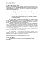
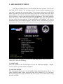
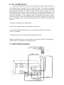
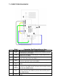
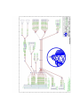
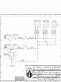
Owner’s Manual
Chicago Gaming Company, 4616 W. 19th Street, Cicero, IL 60804 (708)780-0070
© & ™ 2005 UltraCade Technologies All Rights Reserved
ARCADE LEGENDS
TM
1. LEGAL INFORMATION
1.1 SAFETY NOTICES
The following safety instructions apply to all game owners. We recommend that you
read this page before setting-up Arcade Legends. Use the following safety guidelines to
help protect the system from potential damage and to ensure your personal safety.
•
•
•
•
•
•
•
•
•
•
Use with only 115 volts/60Hz
To help prevent electric shock, plug the system power cables into properly
grounded power sources. These cables are equipped with 3-prong plugs to help
ensure proper grounding. Do not use adapter plugs or remove the grounding
prong from a cable. If you must use an extension cable, use a 3 wire cable with
properly grounded plugs.
To help protect your system from sudden, transient increases and decreases in
electrical power, use a surge suppressor, line conditioner or uninterruptible power
supply (UPS).
Do not spill food or liquid on your system.
Do not push any objects into the openings of the system. Doing so can cause fire
or electric shock by shorting out interior components.
Keep your game far away from radiators and heat sources.
Do not block cooling vents.
Be sure to turn off power before working on the machine
Be sure to use fuses which meet the specified rating. (5A, 220V Quick-blow).
Using fuses exceeding the specified rating can cause a fire and electrical shock.
When working around the monitor, be extremely careful. Monitor parts are
subject to high tension voltage. Even after turning off power some portions are
still subject to high tension voltage. Monitor repair and replacement should be
performed only by technical personnel who have knowledge of electricity and
technical expertise.
1.2 ENVIRONMENTAL CONDITIONS
Arcade Legends is intended for indoor use only. Be sure to keep dry and maintain
operating temperatures of 50-104° Fahrenheit.
1.3 LICENSE INFORMATION JOSHUA OPERATING SYSTEM
The Joshua OSTM is used under license from Joshua Technology, Inc. Joshua
Technology, Inc. retains all rights to the code, trademarks and copyrights. By accepting
and operating an Arcade Legends, the owner/operator the unit agrees to abide by all
copyrights and trademarks and not to attempt to decompile or modify the operating
system in anyway. Questions regarding this operating system should be directed to
technical support at www.ultracade.com or [email protected]. Joshua OS is
copyrighted 2001-2005 by Joshua Technology, Inc.
1.4 WARRANTY INFORMATION
Arcade Legends is warranted against manufacturing defects for 90 days. After that we
will provide free telephone support. If at some point you require warranty service,
contact Chicago Gaming at (708)780-0070. Ask for technical support.
2. GAME SETUP
2.1 PRE-GAME INSTALLATION
Remove the game from the shipping container. Included with the game; is an envelope
containing the game keys, SYSTEM INSTALL CD, and this manual. Connect the wall
cord to a grounded (3-terminal) AC wall outlet. The following precautions should be
followed when installing the game:
•
•
•
•
•
Avoid rough handling of the game; the picture tube is fragile.
Install the game on a level surface.
Avoid installing the game where it will receive excessive sunlight or heat,
to protect the game from rising internal temperatures.
Do not install in a damp or dusty location.
For a short time after connecting the power to the game, the picture may
be temporarily distorted.
The monitor’s purity is affected by the Earth’s magnetic field, causing a variation
of color. By turning the game on for 10 or 15 seconds and then off for 20 or 30 minutes
the automatic degaussing circuit applies a degaussing field around the edges of the
monitor. Doing this a number of times will correct the problem.
Another way to correct the problem is to purchase a degaussing coil or bulk tape
eraser at any electronics store. This will help to immediately demagnetize the video tube.
Caution must be used with a degaussing coil so that the magnetic field of the degaussing
coil is not allowed to become too intense at any one place on the picture tube, thereby
causing a localized color distortion.
If you move the game to another location after degaussing the distortion may
reappear. Refer to the video monitor manual for details.
The game monitor is properly adjusted before shipping. If there are any
adjustments necessary, refer to the video monitor manual. This manual contains all the
manufacturer recommendations for adjusting the video monitor.
Primary monitor adjustments are located behind the faux coin door.
2.2 ON / OFF SWITCH
The On/Off switch is located on the top of the machine in the back right
hand corner.
3. ARCADE SETUP MENU
Press the test button which is located behind the faux coin-door to access the
ARCADE SETUP MENU. The test button can be accessed without opening the faux
coin-door by pressing the coin-return button. If you want to limit access to the TEST
button, open the faux coin door and control panel, loosen the nut on the back of the TEST
button and move it to the left. Be sure to retighten the nut. To choose a menu option,
move the arrow or cursor so that the desired option is highlighted. This is done using the
player one joystick. When the desired option is highlighted, press player one button one
to select it and enter that submenu. In this manual the term “highlight” will mean to
position the arrow over the desired option. The term “select” will mean to press player
one, button one. The exit option on all menus will always go back to a previous menu.
After you press the test button, you will see the ARCADE SETUP menu which will
allow you to access the following:
3.1 LANGUAGE
Move the joystick to the left and right to access the following languages: English,
French, German, Swedish, Italian, and Spanish.
3.2 SOUND VOLUME
This menu option allows you to set the Sound Volume level between one and ten. To
adjust, highlight Sound Volume on the ARCADE SETUP MENU (Fig. 3-1) and move
the joystick to the left or right. Sound for the entire system can be turned off by setting
the value to ZERO.
3.3 GAME CONFIGURATION
This menu allows you to choose which games you wish to display on the main interface
selection screen and to set the dipswitch settings for each game.
Use the following system for navigating this setup menu:
Joystick (Player One):
• Up/down moves left column cursor up or down
• Left/right pages left column cursor up or down
Buttons (Player One):
• Button 1 executes choice or disables/enables a game
• Button 6 enters dipswitch menu for highlighted game
Each installed game comes set to its original factory default dipswitch settings. To
change a game’s settings highlight it and press button six. This will enter you into that
game’s unique dipswitch menu. To change a dipswitch setting, highlight it and move the
joystick either left or right to adjust the setting. To restore the settings to factory defaults,
highlight factory defaults and select.
3.4 DIAGNOSTICS
3.4.1 CONTROL TEST
This test is used to check the functionality of the player controls. Operate each player
control in turn. Each button press or joystick direction will light when activated. If any
controls are not functioning, go to the trouble shooting section. To exit the control test
press both player one and player two start buttons. If one or both start buttons are not
working the control test screen will automatically timeout in fifteen seconds.
3.4.2 JAMMA TEST
The JAMMA Test is similar to the Control Test but it is expanded to encompass the
entire JAMMA harness and connector. Operate each player control in turn through the
JAMMA Test screen and check that it lights up on the screen. This process confirms the
proper working order of the test button, coin drop, and wiring features. To exit the
JAMMA Test press both player one and player two start buttons or wait fifteen seconds
for the test to timeout and exit.
3.4.3 SOUND TEST
Left Channel: You will hear the sound coming from the left speaker.
Right Channel: You will hear the sound coming from the right speaker.
Stereo Test: You will hear the sound coming from both speakers.
High Frequency: You will hear a high pitched sound coming from both speakers.
Low Frequency: You will hear a low pitched sound coming from both speakers.
3.4.4 VIDEO TEST
This feature is a utility to use when making adjustments to the video monitor. When
started, the test will cycle through the following screens: Red, Green, Blue, Color Bars,
and pin cushion.
3.5 CABINET SETUP
3.5.1 RESET FACTORY DEFAULTS
This switch returns all settings to the default state prior to the consumer adjustments.
3.5.2 CABINET TYPE
Use Upright for stand up game, and Cocktail for sit down cocktail table configurations.
3.5.3 SOUND OUTPUT
Stereo setting produces different sound output from each speaker and Mono produces
same sound output from each speaker. Both speakers are used in each setting.
3.5.4 CGA INTERLACE
Off will reduce the screen resolution to 320x240 to reduce flicker in Standard resolution
monitors. On should be used for VGA monitors.
3.5.5 CGA INTERLACE TUNING
When CGA Interlace is OFF, this setting us used to tune the monitor interlacing to reduce
flicker in the interface. This setting has no effect on VGA monitors.
3.5.6 EXIT MENU TIMOUT
The exit menu timeout will make the exit menu return to the main interface automatically
after a set period of time. When Off the exit game button will act as a pause button.
3.5.7 GAMES / MOVIE INTERVAL
This setting sets the amount of games that are shown in the interface before the attract
mode movie and credits are shown. The default value is 3.
3.5.8
DEMONSTRATION MENU
3.5.8.1 ATTRACT MODE SOUND
This option allows you to turn the Attract Mode Volume on or off. When set to “ON” all
attract mode sounds will play. When set to “OFF” the full screen and windowed game
attract mode sounds will not play. To change the values of this option highlight Attract
Mode Volume on the Cabinet Configuration Menu (Fig. 3-10) move the joystick left or
right.
Note: Some games naturally do not play any sound while in attract mode.
3.5.8.2 PROMOTIONAL VIDEO
When this setting is switched to on you can see what new products are available for
Arcade Legends.
3.5.8.3 CONTROL LOCKOUT
When enabled, this setting will disable all inputs except the test button behind the faux
coin door.
3.6 DELETE HIGH SCORE
This menu option allows you to delete all high scores. Pressing the player one button
will clear the game of all high scores.
3.7 TIME ACCOUNTING
Time accounting allows you to track cumulative amount of time spent playing each
game.
3.8 RESET REPORT DATA
Reset Accounting allows you to clear the time accounting.
4. PLAYING A GAME
4.1 SELECT GAME INTERFACE
Use the Joystick up and down to highlight a game to play and then press the player 1 start
button for a single player game. Press the 2 player start button to start a 2 player game.
Some games are simultaneous 2 player games while others are turn based.
4.2 INSTRUCTION SCREEN
The How to Play screen shows a very basic control layout and illustrates what controls
perform which actions for the started game.
4.3 EXIT GAME SCREEN
The “Exit Game?” screen comes up whenever the player presses the exit game button. If
YES is chosen the user to return to the main game select menu. If NO is chosen then the
user will return to the game that was interrupted.
5. TROUBLESHOOTING
5.1 OS RE-INSTALLATION
The Arcade Legends Operating System comes pre-installed but if for any reason you
need to reinstall your Arcade Legends system software, follow the steps below:
1. Open the cabinet and insert the Arcade Legends System CD into the CD-ROM
drive.
2. Turn the Cabinet Off, wait 5 seconds and then turn the cabinet back ON. When
the cabinet reboots you will see the Install menu.
3. Use the Player 1 Joystick to highlight “FORMAT AND INSTALL”, then press
the player one button one to start the installation process.
4. Please contact Ultracade Technologies tech support department at (408) 436-8885
to obtain the correct unlock code for your system. Be ready to provide the CD
serial number and the MCID number located at the bottom of the install screen.
5. Enter the unlock code using the Player 1 joystick and button 1.
6. Once the Arcade Legends systems and games have been installed you can remove
the System CD from the CD-ROM drive. Keep this CD in a safe place in case you
need to use it again.
5.2 TECHNICAL SUPPORT
Free telephone support is provided for the Arcade Legends System.
Technical Support is available from 9:00-5:00 Central Time, Monday through
Friday. Call 1-708-780-0070. Ask for technical support.
6. FCC COMPLIANCE
Note: This equipment has been tested and found to comply with the limits for a
Class B digital device, pursuant to Part 15 of the FCC Rules. These limits are designed
to provide reasonable protection against harmful interference in a residential installation.
This equipment generates uses and can radiate radio frequency energy and, if not
installed and used in accordance with the instructions, may cause harmful interference to
radio communications. However, there is no guarantee that interference will not occur in
a particular installation. If this equipment does cause harmful interference to radio or
television reception, which can be determined by turning the equipment off and on, the
user is encouraged to try to correct the interference by one of more of the following
measures:
--Reorient or relocate the receiving antenna.
--Increase the separation between the equipment and receiver.
--Connect the equipment into an outlet on a circuit different from that to which the
receiver is connected.
--Consult the dealer or an experienced radio/technician for help.
Changes or modifications not expressly approved in writing by UltraCade Technologies
could void the user’s authority to operate the product.
7. COMPUTER DIAGRAM
7. COMPUTER DIAGRAM
Port
Computer Port Description or Use
1
AC Power
2
PS/2
3
USB
4
Video
5
Audio
6
J8 on
USBlinx
AC Power input must use a IEC 14 power cord connector.
Connect the PS/2 cable from the PS/2 port on the computer connects
to the PS/2 port on the USBlinx.
Connect the USB cable from the USB port 1 on the computer to the
USB port on the USBlinx.
Connect the Video cable from the 15-Pin Video Port on the computer
to the 15-Pin Video Port on the USBlinx.
Connect the Audio cable from the Audio Out Port on the computer
connects to the Audio In port on the USBlinx.
Connect the Trackball cable to the 12-Pin connector on the USBlinx
board.
7
J7 on
USBlinx
8
Power
9
JAMMA
Connect the Buttons 5 & 6 with Exit wire harness to the 12-Pin
connector on the USBlinx board. The Buttons 5 & 6 harness is wired in
with the main JAMMA harness.
Connect one of the power connectors from the power supply coming
from the computer to the USBlinx to provide 12vdc and 5vdc power in
the JAMMA harness.
Connect the JAMMA harness to the JAMMA edge on the USBlinx
board.