1
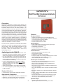
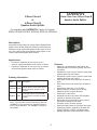
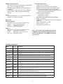
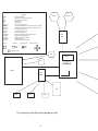
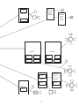
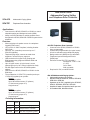
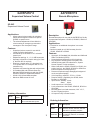
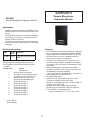
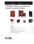
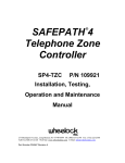
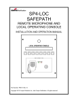
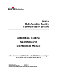
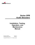
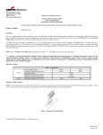
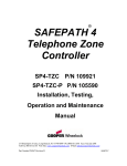
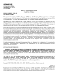
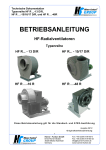
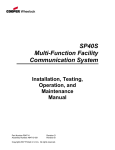
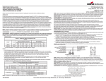
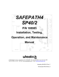
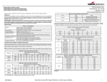
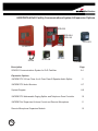
Notification
SAFEPATH®4 DoD Facility Communications System & Expansion Options
SPB-320
SPB-80/4
SPB-160
SP4-APS
SP40S-D
SPRM
SP4Z-A/B
SP-SVC
SP4-TZC
Description
SP40S-D Communications System for DoD Facilities
Page
2-4
Expansion Options
SAFEPATH®4 2-Zone Class A or 4-Zone Class B Speaker Audio Splitter
5
SAFEPATH®4 Audio Boosters
6-7
System Diagram
8-9
SAFEPATH®4 Addressable Paging Splitter and Telephone Zone Controller
10
SAFEPATH®4 Supervised Volume Control and Remote Microphone
11
Remote Microphone Expansion Module
12
UL
®
S5361
SAFEPATH®4
DoD Facility Communications
SP40S-D
Description
Designed for Department of Defense (DoD) facilities, the
SP40S-D is a Multi-Function Supervised Personnel Alerting,
Paging, Background Music delivery and Emergency Voice
Evacuation System with 24 VDC battery backup. The
SP40S-D integrates with fire alarm systems and provides full
control of building audible and visual notification appliances.
This single channel system is capable of delivering 40 watts of
supervised high fidelity audio power and 2 amps of supervised
24 VDC synchronized strobe power. It comes standard with
an on-board digital voice messaging system with 8 standard
messages, a hand-held microphone, power supply/battery
charger and numerous additional features. The SP40S-D
system is expandable to 5280 watts utilizing the SPB-80/4 (80
watts and 4 amps of strobe power), the SPB-160 (160 watts)
or SPB-320 (320 watts) supervised audio power boosters. All
models are available in 115 VAC or 220 VAC.
Features
Background Music
•
•
•
•
Capable of broadcasting from a supplied BGM source
Unique supervision method allows for full system supervision
even during background music (BGM)
Line Level input for music source
Frequency Response 100 - 15KHz
General Paging
To meet the UFC requirement for automatic alarm audible
shutoff after 10 minutes, the SP40S-D includes a 10-minute
time-out feature, which automatically deactivates Fire and
Emergency digital voice (DV) messages inputs 1 - 6 after
10 minutes. Alarm DV messages inputs 7 and 8 do not
automatically time out.
•
•
•
•
Easily interfaces with most existing phone system page port, CO port and line level signals
Automatically mutes BGM
Frequency Response 275 - 6.5kHz
Night ringer or security alert connection
Voice Evacuation
Applications for the SP40S-D
• Supervised NAC speaker and strobe circuits
• Live microphone override
• 8 digitally pre-recorded voice messages
• Emergency digital voice message pushbutton and CC control
inputs automatically deactivate after 10 minutes
• Uses selectable pre-tones for messages
• Multi-use applications—The system can function as an
evacuation, emergency messaging, paging, personnel
alerting and a background music system per NFPA 72
• Fire code applications—The system is listed under UL
Standard 864, 9th edition delivering supervised audio and
voice messaging with strobes and notification appliance
circuits (NAC) for visual alerting
• Economic OSHA applications—The system is OSHA
1910.165 compliant; this means that it does not require
reliability inspections every two months, or the required
spare parts inventory
• Wide ranging applications—from small to large facilities
• Can connect to pagers for private alerting of emergency/
trouble conditions
Strobe Inputs and Activation
• 2 Amps of 24 VDC supervised strobe power with built-in
Wheelock sync protocol; Power limited
• Strobe output is selectable for control of Wheelock sync
protocol or non-sync operation
• Strobe terminals have pass thru capability for Wheelock sync
or non-sync operation
• Any of the 8 messages can be dip switch selected to activate
strobes
• Microphone activation can be dip switch selected to activate
strobes
• Auxiliary activation (Remote MIC) can be dip switch selected
to activate strobes
• 24 VDC supervised and synchronized strobe power can be
expanded to meet the requirements of the installation via
connecting to optional Wheelock power boosters
System Activation
• Contact closure or DV message pushbutton activation
Approvals & Compliance
• Approvals: UL Standard 864, 9th edition, UL Standard 1711
• Meets UFC 10-minute message time-out requirement
• OSHA 1910.165 and ADA Compliant 1 Year Warranty
Speaker Output
2
• 40 watts of supervised audio power
• Speaker outputs: 25V, 70.7V or 100V power limited
Audio Processing
•
•
•
•
•
Volume and tone controls for general paging and BGM
Connectivity of optional speaker splitter modules
Dual-tone tone generator with: Code 3 Tone and Slow Whoop for alerting of system trouble
Night ringer/security alerting capability
Audio power can be expanded by connecting to optional audio power boosters
-SPB-80/4 80 Watt Supervised Audio Power Booster with 4 Amp
of Synchronized Strobe Power
-SPB-160 160 Watt Supervised Audio Power Booster
-SPB-320 320 Watt Supervised Audio Power Booster
Live & Pre-recorded Message Announcement
•
•
•
•
•
•
Supplied with 8 pre-recorded emergency messages
Capable of in-field recording of all messages via 1/8” line level audio input jack
Preset audio levels for emergency messaging (prerecorded and live mic) - system reverts back to a pre set level regardless of the volume set for BGM or general paging
On board Push-to-Talk Microphone
Telephone paging input, disconnects BGM when in use
Auxiliary input for Remote Microphone connection
Benefits of the Multi-Function SP40S-D
•
•
•
•
•
•
Power Supply & Batteries
•
•
24 VDC, 33AH Max rechargeable battery back-up power circuitry built-in
Batteries can be housed in the enclosure (Up to two (BAT-1212), 12 volt, 12 ampere hour batteries can fit in the enclosure.
Actual battery size required will depend on speaker and/or strobe load. Batteries are sold separately).
Installation/Maintenance
• Multiple trouble LED indicators for quick system diagnostics
• Fully supervised circuitry always in effect – even during BGM and
general paging (via patent pending technology)
• Removable quick connect/disconnect terminals for ease of wiring,
accepts #12 to #22 AWG
• Power limited circuitry with Class “B” or Class “A” wiring. Class “A”
only with use of Audio Splitter
• Surge protected circuitry
• Audio and strobe power limiter reset button
Compatible Wheelock Products
All Wheelock Speaker/Strobes
All Wheelock Strobes
All Wheelock Speakers
All Cluster Speakers
Wheelock Strobe Power Supply
One System Multi-Function DoD Facility Communications System
Background Music (BGM) system, with patent pending supervision during
BGM operation
Supervised Emergency/Fire Voice Evacuation System
Interfaces with telephone system for general paging requirements
Built in power for visual notification appliances e.g., Strobes
Expandable for larger system requirements (with optional equipment)
Inputs – Audio and Activation
Priority Ordered Inputs
Priority
Type of Input
Level
On Board Microphone
1
Push to Talk (PTT) Microphone
Auxiliary
2
Remote Microphone or Remote Microphone Expander
Digital Message Input 1
3
Digital Message Input 2
4
Digital Message Input 3
5
Digital Message Input 4
6
Digital Message Input 5
7
Digital Message Input 6
8
Digital Message Input 7
9
Digital Message Input 8
10
Contact Closure activation
Night Ringer Input
11
Contact Closure input
Telephone Paging Input
12
Page port input
Background Music Input
13
Line Level Input, 600 ohm, input voltage must be less then 2.5 V peak to peak, or .3 volts RMS
Audio/Technical Specifications
Mechanical
Switch mode, Class D amplifier (40 Watts)
Dimensions
21” H x 16” W x 6” D
(wall mount)
Weight
36 lbs.
(without batteries)
Finish
Red or black exterior
enclosure
Door Lock
Wheelock Key-lock
Speaker Outputs
Frequency Response
25V, 70.7V or 100V power limited
Voice: 275 Hz – 6.5 kHz
BGM: 100 Hz - 15 kHz
Meets UL Voice Evacuation
Requirements of 800 - 2800 Hz
Signal to Noise Ratio
better than 65 dB
Dynamic Range
better than 65 dB
Total Harmonic Distortion less than 2%
Stand by Current Draw
130 mA
Alarm Current Draw
4.7 amps
3
Ordering Information
Model
Number
Order
Description
Code
SP40S-D
Multi-Function Supervised Paging, Messaging, Background Music delivery and Emergency Voice Evacuation System with 24 VDC battery backup circuitry. Single channel system with 40 watts of supervised
109781
audio power and 2 amps of supervised 24 VDC synchronized strobe power and 8 standard messages.
(batteries not included, 2 required). Red Enclosure. Includes 10-minute message time-out feature.
SP40S-D-B
109854 Same as SP40S-D but with black enclosure
SP40SE-D
109782 Same as SP40S-D but with 220 VAC input
SP40SE-D-B
109855 Same as SP40SE-D but with black enclosure
SP40S-D-PIK
109783 User-interface chip that upgrades the SP40S with the 10-minute message time-out feature
BAT-1212
7390
12 volt, 12-ampere hour battery
SP40S-PMK
9936
SP40S 8 Message Programmed Message Kit
AM-SP40S-SMK
9937
SP40S After Market 8 Message Standard Message Kit
AM-SP40S-PMK
9938
SP40S After Market 8 Message Programmed Message Kit
AM-SP40S-NBT
9939
SP40S After Market Narrow Band Signal Tone Kit
SP-COA
9908
C.O. Port Adapter for the SP40S - Recommended 24 VDC Power Supply is Wheelock RPS-2406 (Order
Code 3770)
BATC-R
5414
Battery Cabinet, Red
BATC-B
5413
Battery Cabinet, Black
BAT-1224
7391
12 Volt, 24Ampere Battery Cell
Message Capabilities
Message
and
Priority #
Type of
Message
Voice
Type
1
Fire
(do not use
elevators)
Male
2
Fire
Three (3) rounds of code 3 horn (followed by): “May I have your attention please! A fire
(do not use Female emergency has been reported in the building. While this is being verified, please leave the
elevators)
building by the nearest exit. Do not use the elevators.”
3
Fire
Male
Message Script
Three (3) rounds of code 3 horn (followed by): “May I have your attention please! A fire
emergency has been reported in the building. While this is being verified, please leave the
building by the nearest exit. Do not use the elevators.”
Three (3) rounds of code 3 horn (followed by): “May I have your attention please! A fire
emergency has been reported in the building. While this is being verified, please leave the
building by the nearest exit.”
4
Three (3) rounds of code 3 horn (followed by): “May I have your attention please! An emergency
Emergency Female has been reported in the building. While this is being verified, please leave the building by the
nearest exit.”
5
Emergency
Male
Three (3) rounds of code 3 horn (followed by): “May I have your attention please! An emergency
has been reported in the building. While this is being verified, please leave the building and report
to the designated assembly area for your group.”
6
Emergency
- Weather
Male
Five (5) seconds of 1kHz tone (followed by): “May I have your attention please! The National
Weather Service has issued a severe weather warning for our area.”
7
Alarm - All
Clear
Male
Five (5) seconds of 1kHz tone (followed by): “May I have your attention please! The building
emergency has ended. An all clear has been given. Please resume normal activities.”
8
Alarm Test
Male
Five (5) seconds of 1kHz tone (followed by). “May I have your attention please! This is a test of
the Wheelock evacuation system, repeat, this is only a test.”
• Each message can be selected to have a code 3 pre-alert tone, a 1kHz continuous pre-alert tone, or no pre-alert tone
• Post-tones are also selectable and match the pre-tones for individual messages
• Any of the 8 messages are field programmable to record your own custom message
• Each message length is 30 seconds
• A 1/8” line level audio input jack is supplied for message recording
• A two step recording procedure is required to ensure and verify that the standard message will be permanently erased
• Factory programmed messages are available for custom messages
• Contact customer service for additional information
• Form is required and can be downloaded from www.coopernotification.com
Note: For telephone paging, the SP40S-D can connect directly into the page port of the local phone system. If a page port is inaccessible, the SPCOA (C.O. Port Adapter for the SP40S-D) may be used to connect the SP40S-D to an unused C.O. port or stand-alone telephone.
Wheelock products must be used within their published specifications and must be PROPERLY specified, applied, installed, operated, maintained
and operationally tested in accordance with their installation instructions at the time of installation and at least twice a year or more often and
in accordance with local, state and federal codes, regulations and laws. Specification, application, installation, operation, maintenance and
testing must be performed by qualified personnel for proper operation in accordance with all of the latest National Fire Protection Association
(NFPA), Underwriters’ Laboratories (UL), National Electrical Code (NEC), Occupational Safety and Health Administration (OSHA), local, state,
county, province, district, federal and other applicable building and fire standards, guidelines, regulations, laws and codes including, but not
limited to, all appendices and amendments and the requirements of the local authority having jurisdiction (AHJ).
4
SAFEPATH®4
2-Zone Class A or 4-Zone Class B
2-Zone Class A
or
4-Zone Class B
Speaker Audio Splitter
Speaker Audio Splitter
For operation with SAFEPATH®4 Family of Products:
SP40S, SP40S-D SP40/2, SPB-320, SPB-160, SPB-80/4
Description:
Supervised 2-Zone Class A or 4-Zone Class B Speaker Audio
Splitter for the SP40S, SP40S-D, SP40/2 or Audio Boosters.
Enables a single supervised speaker audio output to drive
up to two Class A supervised speaker audio outputs or four
Class B supervised speaker audio outputs.
Applications:
• Provides for expansion of one zone to up to 2 zones of supervised speaker audio output in Class A
Features:
•
• Provides for expansion of one zone to up to 4 zones
of supervised speaker audio output in Class B
•
•
Ordering Information:
Model
•
Order
Code Description
SP4Z-A/B
9900
Supervised 2-Zone Class A or 4-Zone
Class B Speaker Audio Splitter for the
SP40S, SP40S-D, SP40/2 or Audio
Boosters
SPMB4Z
9907
Mounting Bracket for the SP4Z-A/B
is required when used with the Audio
Boosters
•
•
•
•
•
•
•
Note: The Speaker Splitter-Mounting Bracket
(SPMB4Z) is required when the Speaker Splitter is
used in Audio Boosters. The SPMB4Z can support
two splitters.
•
•
•
•
5
Approvals: UL Standard 864, 9th edition, and
California State Fire Marshal (CSFM), New York
City (MEA)
Expands one zone to up to 2 zones of supervised
speaker audio output in Class A
Expands one zone to up to 4 zones of supervised
speaker audio output in Class B
Each Class A zone can accept up to 40 watts of
audio
Each Class B zone can accept up to 40 watts of
audio
Operates on either 25V or 70.7V RMS
Mounts inside the enclosure of the SP40S,
SP40S-D, SP40/2 or Audio Boosters
Power and Trouble LED’s
Individual zone short and open LED indication
Capable of detecting wiring faults
Removable wiring terminals for quick connect/
disconnect accepting 12–22 AWG
All output circuitry is Power Limited
Space provided to allow for naming of the zones
Powered by 24VDC, supplied by the either the
SP40S, SP40S-D, SP40/2 or Audio Boosters
Standby and Alarm current at 24VDC is 15mA
SAFEPATH®4
Audio Boosters
SPB-320
320 Watt Supervised Audio Power Booster (Four 80 watt circuits)
SPB-160
160 Watt Supervised Audio Power Booster (Two 80 watt circuits)
SPB-80/4
80 Watt Supervised Audio Power Booster with 4 Amps of Supervised and Synchronizable
Strobe Power (Two 2 Amp circuits)
SPB-320
SPB-80/4
SPB-160
Features
Approvals & Compliance
• Approvals: UL Standard 864, 9th edition, UL Standard 1711, California State Fire Marshal (CSFM), New York City (MEA)
• OSHA 1910.165, and ADA
• 1 Year Warranty
System Activation: Audio
Description
Supervised Facility Communication and Emergency Voice
Evacuation Audio and Audio/Strobe Power Boosters, UL
Standard 1711 and UL Standard 864, 9th edition with
24VDC battery backup capabilities. Designed to provide
for additional supervised audio power for live voice, prerecorded messages or background music (BGM). Fully
supervised patent pending circuitry is always in effect even
during BGM. The SPB-80/4 also provides 4 Amps of 24 VDC
Supervised and Synchronized Strobe Power.
•
•
System Activation: Strobe (SPB-80/4)
• 8 - 33VDC NAC input connected to the strobe input
The SPB-320, SPB-160 and the SPB-80/4 easily connects to
the SP40S, SP40S-D, or SP40/2. Multiple SPB-320, SPB160 and SPB-80/4 Audio Boosters can be inter-connected
to accommodate large installations with supervised audio
power and also supervised and synchronized strobe power
requirements.
Power Supply & Batteries
• Fully supervised patent pending circuitry always in effect even during BGM
• Power limited circuitry
• Class D amplifiers
• Internal battery charger and power supply • Required batteries fit inside the enclosure (sold separately)
• SPB-320 requires four 12 VDC, 12 AH batteries
• SPB-160 and SPB-80/4 require two 12 VDC, 12 AH batteries
Outputs:
• SPB-320 has four 80 watt speaker output circuits
• SPB-160 has two 80 watt speaker output circuits
• SPB-80/4 has one 80 watt speaker output circuit and two 2 amp strobe circuits (4 amps total)
• Supervised Audio Speaker outputs: 70V or 25V field selectable (all boosters must be either 70 V or
25 V)
• Expansion output (supervised, 24VDC at .5A in alarm condition) used for connecting multiple boosters
• DC output (unsupervised for optional splitter power). Each speaker circuit (four for the SPB-320, two for the SPB-160, one for the SPB-80/4) can connect to
speaker splitters
The SPB-320 draws 2.4 watts of audio input power to
properly operate and provide additional supervised audio
output power. The SPB-160 and the SPB-80/4 draws 1.2
watts of audio input power to properly operate and provide
additional supervised audio output power. A maximum of
5,280 watts of supervised audio power can be achieved.
Additional strobe power can be obtained via a combination
of SPB-80/4 or Wheelock Power Supplies/Chargers.
Applications
•
•
•
70V or 25V input from the SP40S, SP40S-D or SP40/2
1 Volt input from SP4-RMX
Provides for additional supervised audio power for
large installations
Provides for additional supervised and synchronizable
strobe power for large installations
Can be used in new construction as well
as in retrofit construction
6
SPB-80/4 Strobe Features:
• Two 24VDC 2 Amps, NAC supervised, synchronizable, power limited, Class B strobe outputs
• Selectable outputs; Wheelock sync, pass through, or constant DC
• Trouble LED’s for open and short output conditions
• Alarm indicator: LED’s for Strobe and Expansion Outputs
Inputs:
• Audio Speaker Inputs: 70V or 25V, field selectable
• Auxiliary in (for alarm input signal)
Mechanical:
SPB-160, SPB-80/4
• Dimensions: 21” H x 16” W x 6” D (wall mount)
• Weight:
36 lbs. (without batteries)
• Finish:
Red exterior enclosure
• Door Lock: Wheelock key-lock
SPB-320
• Dimensions:
• Weight:
• Finish:
• Door Lock:
36” H x 24” W x 6” D (wall mount)
80 lbs. (without batteries)
Red or black exterior enclosure
Wheelock key-lock
Technical Specifications:
• 120VAC, 3.8A, 60 Hz input
• SP40SE-D Models 240 VAC, 2.5A, 50-60 Hz
• Standby current draw: 120mA, per amplifier board
• Alarm current draw:9 Amps, per amplifier board
SPB-80/4 and SPB-160 have one amplifier board
SPB-320 has two amplifier boards
• System Frequency Response:
Voice 400 Hz - 6.5 kHz
BGM 275 Hz - 15 kHz
• Removable quick connect/disconnect terminals, accept 12 - 22 AWG
• Multiple LED’s for easy indication of system diagnostic conditions
• Signal to Noise Ratio: > 70 dB
• Dynamic Range: > 65 dB
• Total Harmonic Distortion: 2%
Note: The Speaker Splitter-Mounting Bracket
(SPMB4Z) is required when the Speaker Splitter is
used in Audio Boosters. The SPMB4Z can support
two splitters.
Ordering Information
Model
Order
Code
Description
SPB-320
9918
320 Watt Supervised Audio Power Booster (Four 80 watt circuits)
SPB-320E
6336
320 Watt Supervised Audio Power Booster (Four 80 watt circuits), 220 VAC input
6353
320 Watt Supervised Audio Power Booster (Four 80 watt circuits), 220 VAC input, black
enclosure
SPB-160
8989
160 Watt Supervised Audio Power Booster (Two 80 watt circuits), red enclosure
SPB-160-B
9930
160 Watt Supervised Audio Power Booster (Two 80 watt circuits), black enclosure
SPB-160E
6149
160 Watt Supervised Audio Power Booster (Two 80 watt circuits), 220 VAC input
SPB-160E-B
6150
160 Watt Supervised Audio Power Booster (Two 80 watt circuits), 220 VAC input, black
enclosure
SPB-80/4
8988
80 Watt Supervised Audio Power Booster with 4 Amps of Supervised and Synchronized
Strobe Power (Two 2 Amp circuits), red enclosure
SPB-80/4-B
9931
80 Watt Supervised Audio Power Booster with 4 Amps of Supervised and Synchronized
Strobe Power (Two 2 Amp circuits), black enclosure
SPB-80/4E
6147
80 Watt Supervised Audio Power Booster with 4 Amps of Supervised and Synchronized
Strobe Power (Two 2 Amp circuits), 220 VAC input
SPB-80/4E-B
6148
80 Watt Supervised Audio Power Booster with 4 Amps of Supervised and Synchronized
Strobe Power (Two 2 Amp circuits), 220 VAC input, black enclosure
SPMB4Z
9907
Speaker Splitter Mounting Bracket for SPB-320, SPB-160 or SPB-80/4
SPB-320E-B
7
Legend:
BGM
DV
FACP
MPS
NPS
Wheelock
SP40S
SP40S-D
SPB-80/4
SPB-160
SPB-320
SPRM
SP4-RMX
SP4-TZC
SP4-APS
SP4Z-A/B
SP4-SVC
Strobe
BGM
Background Music
Digital Voice Message Expander
Fire Alarm Control Panel
Pull Station
Push Station
Strobe Power Supplies
Supervised Multi-Function Communication System
80 Watt Audio Booster & 4 Amps of Strobe Power
160 Watt Audio Booster
320 Watt Audio Booster
Remote Microphone
Remote Microphone Expansion Module
Telephone Zone Controller
Addressable Paging Splitter
Speaker Splitter
Supervised Volume Control
Speaker
Speaker Strobe
Telephone
SP4TZC
Cluster Speaker
S
V
Volume Control
NPS
SP4-APS
MPS
SP40S
SP40S-D
FACP
SP4-3MEM
SP4RMX
DV
SPRM
SPRM
SPRM
T his drawing is for illustrative purposes only
8
SP4-APS
Wheelock
Strobe
Power
Supply
V
SPB-160
Wheelock
Strobe
Power
Supply
SP4Z-A/B
SPB-320
SPB-80/4
SPB-320
SP4-APS
SP4-APS
SP4-APS
SP4-APS
SP4-APS
SP4Z-A/B
SP4Z-A/B
SP4-APS
SP4-APS
SP4-APS
SPB-160
SPB-160
SP4-APS
SP4-APS
V
SP4-APS
9
V
SAFEPATH®4
SP4-APS
Addressable Paging Splitter
SP4-TZC
Telephone Zone Controller
Addressable Paging Splitter
and Telephone Zone Controller
Applications:
• Connects to the SP40S, SP40S-D or SP40/2 to control selectable paging and background music (BGM)
•
Ability to access individual or multiple speaker zones throughout the SP40S, SP40S-D or SP40/2 system via the telephone
Features:
•
•
•
•
•
•
•
•
•
Allows selections of speaker zones via a telephone
keypad (DTMF tones)
UFC 04-021-01 2002 Compliant, including October
2007 Draft
One SP4-TZC (controller) can control up to 17
SP4-APS (splitters)
Telephone page input connects to stand alone
telephone, unused CO port, page port
USB connection for logical zone grouping and
BGM programming (supports Windows 2000 and
Windows XP)
Up to 9 logical zones, (a logical zone is a user
selected group of up to 5 zones, individual or fixed)
RS-485 digital control to the SP4-APS speaker
splitters
Connects to the SP40S, SP40S-D or SP40/2 via the
BGM input
The combination of 1 SP4-TZC (controller) and up to
17 SP4-APS (splitters) can provide:
Class B
4 zones per splitter
Up to 68 individual zones (17 splitters)
17 fixed zones (groups of 4) 9 logical zones SP4-TZC Telephone Zone Controller:
• Connects to the SP40S, SP40S-D or SP40/2
• Auto programmable
• Custom user programmable (for logical zones)
• All call or selected zone(s) telephone paging
• Background music (BGM) zone(s) selectable
• Telephone input and background music
(BGM) input
• Enclosure for the SP4-TZC (controller):
Dimensions: 13”H x 7.6”W
x 2.15”D
Color: Black
Wall mountable
• Requires 24 VDC, model RPS-2406
SP4-APS Addressable Paging Splitter:
• Addressable speaker zone splitter
• Mounts inside the SP40S-D, SP40/2, SPB-80/4,
SPB-160 or SPB-320
• Operates on 24 VDC, supplied by the SP40S-D,
SP40/2, SPB-80/4, SPB-160, SPB-320
• Handles 40 watts of supervised audio per zone
• UL Standard 864, 9th edition listed
Class A
2 zones per splitter
Up to 34 individual zones (17 splitters) 17 fixed zones (groups of 2)
9 logical zones
Ordering Information:
Model
Order
Code
Description
SP4Z-APS
9920
Addressable Paging Splitter
SP4-TZC
9921
Telephone Zone Controller
TZC-USB
9923
SP4-TZC Programming Cable
10
SAFEPATH®4
SAFEPATH®4
Supervised Volume Control
Remote Microphone
SP-SVC
Supervised Volume Control
Applications:
•
•
Description:
Allows manual volume setting for telephone
paging and background music for a specific
speaker or speaker zone
The selected adjustment will not affect the
volume setting of emergency prerecorded
messages or live microphone usage
Remote Microphone for use with the SAFEPATH®4 Facility
Communications System - SP40S-S, SP40S-D, SP40/2 or
SP4-RMX
Applications:
• Provides for an additional microphone in a remote
location
• Can be mounted up to 2,000 feet away from the
SP40S, SP40S-D or SP40/2
Features:
•
Supervised volume control for use with UL
Listed Life Safety Applications
• Can handle up to 35 watts of 70.7 volt audio
power input
• Adjustment settings: 0 – 10, in 3dB increments
• Operates in Class B or Class A wiring (for Class
A, the SP4-APS is required)
•· Requires a double gang, 3½” deep back box
or 4” square and 1-1/2” deep box with a 1-1/2”
extension ring
• Stainless steel mounting plate with a black knob
• UL Standard 864 and California State Fire
Marshal (CSFM) listed for use with the SP40S,
SP40S-D, SP40/2 or SPB Audio Boosters
• OSHA 1910.165 and ADA compliant
• Maximum RMS current 10.0mA
Features:
•
•
• •
•
•
•
•
•
•
•
•
•
Ordering Information:
Model
Order
Code
Description
SP-SVC
9926
Supervised Volume Control for use
with the SAFEPATH®4 system
Approvals: UL Standard 864, 9th edition and California
State Fire Marshal (CSFM)
Supervised hand held push to talk microphone
Key required to enable remote microphone use
Individual front panel LED indication for; System
Normal, System Trouble and Alarm
When used with the SP40S, SP40S-D or SP40/2, the
priority level is 2, the SP40S, SP40S-D or SP40/2 on
board microphone is always priority 1
Remote microphone usage disengages background
music and general paging
Voice frequency response: 275 Hz - 6.5 kHz
Requires 24VDC, supplied by the SP40S, Audio
Boosters, or SP4-RMX
Input current: Standby: 23mA
Alarm: 30mA
Audio output level: 1.05V RMS
6 wire connection to the SP40S, SP40S-D, SP40/2 or
SP4-RMX
Mounting plate is red and measures, 8 3/4” x 5 ¼”,
fits into a 4 gang back box
All output circuitry is Power Limited
Ordering Information:
11
Model
Order
Description
Code
SPRM
8996
Remote Microphone for use with SP40S,
SP40S-D SP40/2, SPB-320, SPB-160,
SPB-80/4 or SP4-RMX, red plate
SPRM-GP
9927
General Paging Microphone for use with
the SPB-320, SPB-160, or SPB-80/4,
black plate
SAFEPATH®4
Remote Microphone
SP4-RMX
Remote Microphone Expansion Module
Expansion Module
Applications:
• Expands one remote microphone (SPRM) from the •
•
SP40S, SP40S-D or SP40/2 to three remote micro
phones
Two SP4-RMX modules can be cascaded together to provide up to six remote microphones from the SP40S, SP40S-D or SP40/2
Provides for an auxiliary input for connection of an external VoiceLink message repeater for additional messages
Features:
Ordering Information:
Model
Order
Code
Description
SP4-RMX
9919
Remote Microphone Expansion
Module
•
The SP4-RMX will provide the capability of connecting
up to (3) three Remote Microphone Stations (SPRM)
• When connected to the SP40S, SP40S-D or SP40/2,
two SP4-RMX units can be cascaded together to
provide up to six remote microphones
• Provides for an auxiliary input for connection of an
external message repeater, for additional messages
• Can accept a line level input for broadcasting of other
information
• When the SP4-RMX is connected to the SP40S,
SP40S-D or SP40/2, the entire system benefits from
the additional microphone capability
• Can be connected to Audio Boosters for general (nonalarm) paging with use of SPRM-GP
• UL Standard 864 listed
• OSHA 1910.165, ADA and UFC 04-021-01 2002
Compliant, including October 2007 Draft
• Multiple on board diagnostics with 3 status conditions:
standby, alarm, and trouble
• Operates on 24 VDC, supplied by the SP40S,
SP40S-D, SP40/2, SPB-80/4, SPB-160, SPB-320
• The SP4-RMX is an external module
Enclosure dimensions: 13”H x 7.6”W x 2.15”D
Microphone and message priority levels when
the SP4-RMX is used with the SP40S, SP40S-D
or SP40/2:
Priority Level
Device
Microphones
1
SP40 on board microphone
2
SP4-RMX, remote microphones #1, 2,
3 (set priority or First In First Out)
3
SP4-RMX, auxiliary input only
SP40S-D Standard Messages
4
SP40S-D message 1
5
SP40S-D message 2
6
SP40S-D message 3
7
SP40S-D message 4
8
SP40S-D message 5
9
SP40S-D message 6
10
SP40S-D message 7
11
SP40S-D message 8
Color: Black
Wall mountable
12
Ordering Information
Model Number
Order
Description
Code
SP40S-D
109781
SP40S-D-PIK
109783 Upgrades the SP40S with the 10-minute message time-out feature
Multi-Function Supervised Paging, Messaging, Background Music and Emergency Voice Evacuation
System with 24 VDC battery backup circuitry. Single channel system with 40 watts of supervised
audio power and 2 amps of supervised 24 VDC synchronized strobe power and 8 standard messages.
(batteries not included, 2 required). Red enclosure. Includes 10-minute message time-out feature.
SP40S-PMK
9936
SP40S 8 Message Programmed Message Kit
AM-SP40S-SMK
9937
SP40S After Market 8 Message Standard Message Kit
AM-SP40S-PMK
9938
SP40S After Market 8 Message Programmed Message Kit
AM-SP40S-NBT
9939
Sp40S After Market Narrow Band Signal Tone Kit
9908
C.O. Port Adapter for the SP40S or SP40/2 - Recommended 24 VDC Power Supply is Wheelock RPS2406 (Order Code 3770)
9900
Supervised 2-Zone Class A or 4-Zone Class B Speaker Audio Splitter for the SP40S, SP40/2 or Audio
Boosters
SPMB4Z
9907
Mounting Bracket for the SP4Z-A/B is required when used with the Audio Boosters
SPB-320
9918
320 Watt Supervised Audio Power Booster (Four 80 watt circuits)
SPB-160
8989
160 Watt Supervised Audio Power Booster (Two 80 watt circuits), red enclosure
SPB-160-B
9930
160 Watt Supervised Audio Power Booster (Two 80 watt circuits), black enclosure
8988
80 Watt Supervised Audio Power Booster with 4 Amps of Supervised and Synchronized Strobe Power
(Two 2 Amp circuits), red enclosure
9931
80 Watt Supervised Audio Power Booster with 4 Amps of Supervised and Synchronized Strobe Power
(Two 2 Amp circuits), black enclosure
SP4Z-A/B
9900
Supervised 2-Zone Class A or 4-Zone Class B Speaker Audio Splitter for the SP40S, SP40/2, SPB-320,
SPB-160 or SPB-80/4
SPMB4Z
9907
Speaker Splitter Mounting Bracket for SPB-320, SPB-160 or SPB-80/4
SP4Z-APS
9920
Addressable Paging Splitter
SP4-TZC
9921
Telephone Zone Controller
TZC-USB
9923
SP4-TZC Programming Cable
SP-SVC
9926
Supervised Volume Control for use with the SAFEPATH®4 System
SPRM
8996
Remote Microphone for use with the SP40S, SP40S-D, SP40/2, SPB-320, SPB-160, SPB-80/4 or SP4RMX, red plate
SPRM-GP
9927
General Paging Microphone for use with the SPB-320, SPB-160 or SPB-80/4, black plate
BATC-R
5414
Battery Cabinet, Red
BATC-B
5413
Battery Cabinet, Black
BAT-1212
7390
12 Volt, 12 Ampere Battery Cell
BAT-1224
7391
12 Volt, 24 Ampere Battery Cell
BAT-1265
7392
12 Volt, 65 Ampere Battery Cell
SP-COA
SP4Z-A/B
SPB-80/4
SPB-80/4-B
13
Architects and Engineers Specifications
SP40S-D DoD Facility Communications System
The system shall be a multi-purpose, supervised, general-purpose audio, and fire/emergency evacuation system with a 10-minute message
time-out feature as required by the UFC. The system shall be a single channel voice evacuation system incorporating supervision during
the broadcasting of background music and general paging. The system shall be capable of delivering 40 watts of supervised audio
power and 2 amps of supervised 24 VDC synchronized strobe power. Minimum supervised audio power shall be 40 watts, expandable
to 5280 watts, depending on system configuration and with additional modules and power boosters. Supervised 24 VDC synchronized
strobe power shall be 2 amps, expandable to the requirements of the installation. The system shall be capable of operating from a 120
VAC power source. E models shall be capable of operating from a 240 VAC power source. All models shall have a 24 VDC battery
backup. Standard on-board system features shall include: digital voice messaging, a hand-held push-to-talk microphone with override
priority, and a power supply/battery charger. The system shall be capable of interfacing with telephone systems for general paging
announcements and will have night ringer capabilities. Form C contacts shall be provided for system alarm and trouble conditions.
The system shall have 8 message contacts with contact closure activation. Background music input voltage shall be capable of
handling less then 2.5 V peak to peak or less then .3 volts. The system shall have thirteen priority ordered inputs, including: On Board
Microphone, Auxiliary Input (Line Level), 8 Digital Messages, Night Ringer Input, Telephone Paging Input, and Background Music Input.
The system shall have preset audio levels for emergency messaging (prerecorded and live mic). The system shall revert back to a
preset level regardless of the volume set for background music (BGM) or general paging. Background music inputs can be an AM/FM
tuner, cassette, CD, MP3, or any other remote source. The system shall be supplied with 8 pre-recorded messages and be capable of
in-field recording of customer unique messages. The system shall have a dual-tone tone generator with Code-3 Tone and Slow Whoop.
When the system is on battery power, telephone page, night ring and background music shall be disengaged.
The panel shall have power-limited circuitry with an internal battery charger and power supply. The power supply/charger section shall
be able to charge 24 VDC batteries with a maximum capacity of 33 amp hours. Up to two 12 VDC, 12 AH batteries may be housed in
the enclosure. Batteries larger than 12 Ah shall be housed in a separate enclosure such as the Cooper Wheelock BATC or equivalent.
Batteries shall be supplied separately.
The system shall have power limited circuitry and class B wiring. Wiring terminal blocks will be removable and accept #22 - #12 AWG
wire. Audio output voltage shall be selectable for 25V or 70.7V. The voice (live microphone or recorded message) frequency response
shall be 275 Hz – 6.5 kHz, background music frequency response shall be 100 Hz - 15 kHz. Stand by current draw shall be 140mA.
Alarm current draw shall be 4.7 amps. The signal to noise ratio shall be better than 65 dB, dynamic range shall be better than 65 dB,
total harmonic distortion shall be less than 2%.
The system shall be wall mountable, enclosed in a steel locking enclosure. The required batteries for 40-watt systems shall fit inside the
enclosure. The 40 watt system shall weigh no more than 36 lbs (without batteries) and its dimensions shall not exceed 21” H x 16” W
x 6” D. Approvals for the system shall include: UL Standard 864, 9th edition, UL Standard 1711. The system shall be OSHA 1910.165,
ADA compliant. 1 Year Warranty.
SAFEPATH®4 Audio Boosters
The Wheelock SPB-320, SPB-160 and SPB-80/4 Audio Boosters shall be NFPA compliant supervised audio and supervised 24VDC
synchronized strobe power boosters (some models will have supervised 24VDC synchronized strobe booster capability). The booster
shall have 24VDC battery backup capabilities. The booster shall have the capability to supervise the circuitry during playback of
background music. The booster shall have the capability to be inter-connected to accommodate large installations with supervised
audio power and also supervised and synchronized strobe power requirements. Three versions of the booster shall be made available:
SPB-80/4, (80 watts of supervised audio power and 4 amps of supervised and synchronized strobe power), SPB-160 (160 watts of
supervised audio) or SPB-320 (320 watts of supervised audio).
Each booster shall use 1.2 watts of audio input power (The SPB-320 requires 2.4 watts of audio power) to properly operate and provide
additional supervised audio output power. A combination of boosters can be added together to provide for a maximum of 5,280 watts of
supervised audio power. Additional strobe power can be obtained via a combination of boosters. The audio section of the booster shall
be connected via a selectable 70V or 25V input from the SP40S or SP40S-D. The strobe section of the booster shall be divided into two
sections each supplying two Amps of 24VDC, NAC, supervised, synchronizable, power limited, Class B strobe outputs, with selectable
outputs offering Wheelock sync, pass through, or constant DC and can be activated via 8-33VDC NAC input or contact closure.
The internal battery charger/power supply shall be capable of charging 24 VDC batteries with a maximum capacity of 33 amp hours.
The enclosure shall be capable of housing the correct number of 12 VDC rechargeable batteries (SPB-80/4 (2), SPB-160 (2), SPB-320
(4)) with a maximum capacity of 12 Amp hours. Batteries with a larger capacity require an external battery enclosure(s) such as the
Cooper Wheelock BATC or equivalent.
The boosters shall have power-limited circuitry and be a class D amplifier with an internal battery charger and power supply. The required
batteries (purchased separately) shall fit inside the enclosure (two 12VDC, 12 AH for the SPB-80/4 or SPB-160 and four 12 VDC, 12 AH
for the SPB-320). The booster shall operate on 120VAC, 3.8A, 50 – 60 Hz input. E model boosters shall operate on 240 VAC, 2.5A, 50
– 60 Hz input. The SPB-80/4 or SPB-160 standby current draw shall be 120mA and alarm current draw shall be 9 Amps. The SPB-320
consists of two SPB-160’s. Each SPB-160 shall have its own power supply and battery charger. The voice frequency response shall
be 400 Hz – 6.5 kHz +/- 3 dB, the BGM frequency response shall be 275 Hz - 15 kHz +/- 3 dB. Removable quick connect/disconnect
terminals that accept 12 -22 AWG shall be used. Multiple LED’s for easy indication of system diagnostic conditions shall be present
on the PC board. The Signal to Noise Ratio shall be > 70 dB, the dynamic range shall be > 65 dB, the Total Harmonic Distortion spec
shall be 2%.
The booster shall be wall mountable, enclosed in a steel locking enclosure, with a red finish. Approvals for the booster shall include;
UL Standard 864, 9th edition, UL Standard 1711, CSFM and MEA. The system shall be OSHA 1910.165, and ADA compliant. The
booster shall carry a 1 Year Warranty.
The SPB-80/4 & SPB-160 enclosure dimensions are 21” H x 16” W x 6” D and the SPB-320 enclosure dimensions are 36” H x 24” W
x 6” D.
14
Architects and Engineers Specifications
4 Zone Class B Speaker Splitter
The Wheelock SP4Z-A/B shall be UL Standard 864, 9th edition, California State Fire Marshal (CSFM) and New York City (MEA)
approved, 2-Zone Class A or 4-Zone Class B Speaker Splitter for operation with the Wheelock, SP40S, SP40S-D, SP40/2, SPB-80/4,
SPB-160 and SPB-320. The SP4Z-A/B shall enable a single supervised speaker audio output to drive up to two Class A supervised
speaker audio outputs or four Class B supervised speaker audio outputs. Each Class A zone shall be capable of accepting up to
40 watts and operate on either 25 or 70.7V RMS of audio input. Each Class B zone shall be capable of accepting up to 40 watts of
audio and operate on either 25 or 70.7V RMS of audio input. The SP4Z-A/B shall be capable of supporting live microphone paging,
prerecorded emergency voice evacuation messages, supervised background music and general paging announcements.
The SP4Z-A/B shall mount inside the enclosure of the SP40S, SP40S-D, SP40/2, SPB-80/4, SPB-160 and SPB-320 and shall have
power and trouble LED’s with individual zone short and open LED indication. The SP4Z-A/B shall be capable of detecting wiring
faults. The SP4Z-A/B shall be powered by 24VDC, which is to be supplied by the SP40S, SP40/2, SPB-80/4, SPB-160 or SPB-320.
Standby and Alarm current at 24VDC shall be 15mA. Removable wiring terminals for quick connect/disconnect accepting 12–22
AWG shall be incorporated. All output circuitry shall be power limited. Space shall be provided to allow for naming of the zones.
Addressable Paging Splitter and Telephone Zone Controller
The Wheelock Addressable Paging Splitter (SP4-APS) and Telephone Zone Controller (SP4-TZC) shall be used to control and
direct telephone paging and background music zones connected to the SAFEPATH4 Multi-Function Facility Communication System
using an RS485 connection.
The Addressable Paging Splitter (SP4-APS) shall be UL Standard 864, 9th edition and California State Fire Marshal (CSFM)
approved, addressable and supervised 2-zone Class A or 4-zone Class B Speaker splitter. The SP4-APS shall be used with
Wheelock’s SP40S, SP40S-D or SP40/2 panel and the Audio Booster (SPB-160, SPB-80/4, and SPB-320) panels. Each SP4APS shall have a single audio input capable of 25 Vrms or 70.7 Vrms at a maximum of 80 Watts. The input audio power shall be
distributed to the zone connections with the total not exceeding the input and no zone exceeding 40 Watts. When audio boosters
are connected, each audio booster module shall consume 1.2 Watts from the total input power of the SP4-APS. The splitter shall
be mounted inside the SP40S, SP40S-D, SP40/2 or Audio Booster that it is associated with, and it shall operate on 24VDC supplied
by the supported module. The SP4-APS shall contain 16 LED indicators used to monitor and troubleshoot the module.
The Telephone Zone Controller Module (SP4-TZC) shall be used to address the output zones on the SP4-APS. The SP4-TZC shall
be capable of supporting 17 SP4-APS speaker splitter modules and shall be capable of addressing all zones at once (“All Call”), a
maximum of 68 separate zones, 17 fixed zone groups and 9 programmed logical zone groups. This shall be accomplished using
two digit DTMF tones from a page port, an unused CO port, or a stand alone telephone with a loop start circuit. Also, the SP4TZC shall be able to select zones for background music. The SP4-TZC has the following inputs: Power, USB port, Background
Music (BGM), Page Audio in. The outputs are: Audio out and RS485 Digital Control. The basic operating parameters of the SP4APS shall be pre-programmed. Customized programming shall be accomplished using a USB cable and programming computer
software. The SP4-TZC shall be powered using a 24VDC filtered and regulated power supply such as the Wheelock RPS-2406.
The Controller Module assembly is mounted in a metal enclosure measuring 13”L x 7 5/8”W x 2”D.
Supervised Volume Control
The Wheelock SP-SVC shall be UL Standard 864, 9th edition approved, supervised volume control for use with the SAFEPATH®4
Facility Communications System.
The SP-SVC shall provide for manual volume setting for telephone paging and background music for a specific speaker or speaker
zone. The selected adjustment will not affect the volume setting of emergency prerecorded messages or live microphone usage.
The SP-SVC shall be capable of handling up to 35 watts of audio power @ 70.7 volts or 4 watts audio power @ 25 volts and shall
operate on either 70.7 or 25 volt input from an SP40S, SP40S-D or Audio Booster. The SP-SVC shall be capable of operating
in Class B or Class A wiring configurations (for Class A, the SP4-APS is required). The SP-SVC shall receive operating power
from an Audio Booster, SP40S, SP40S-D or SP40/2. Volume adjustment settings shall be off, 1 – 10, in 3dB increments. The
SP-SVC shall be supplied with a stainless steel mounting plate with a black knob and require a double gang, 3½” deep back box
for mounting.
Remote Microphone
The Wheelock SPRM shall be UL Standard 864, 9th edition and California State Fire Marshal (CSFM) approved, Remote
Microphone for use with the SAFEPATH®4 Facility Communications System.
The SPRM shall be a supervised hand held push to talk microphone and a key shall be required to enable remote microphone use.
(Same key as SP40S, SP40S-D or SP40/2) Removable wiring terminals for quick connect/disconnect accepting 12 – 22 AWG
shall be incorporated. All output circuitry shall be power limited. Individual front panel LED’s shall be provided for indication of
System Normal, System Trouble and Alarm. Multiple on board diagnostic LED’s shall be provided. When used with the SP40S,
SP40S-D or SP40/2, the priority level shall be number two. Remote microphone usage shall disengage background music and
general paging.
Voice frequency response shall be 275 Hz - 6.5 kHz +/- 2.4 dB. Power requirements shall be 24VDC and will be supplied by the
SP40S, SP40S-D or SP40/2. Input current for Standby shall be 26mA and for Alarm 38mA. Audio output level shall be 1.05V
RMA. There shall be a 6-wire connection to the SP40S, SP40S-D or SP40/2. The mounting plate shall be red and measure, 8
3/4” x 5 ¼”, and shall fit into a 4 gang back box.
15
Remote Microphone Expansion Module
The Wheelock SP4-RMX Remote Microphone Expansion Module shall be UL Standard 864, 9th edition and California State Fire Marshal
(CSFM) approved for use with the SAFEPATH®4 SPS40 and SP40S-D Facility Communications Systems.
The SP4-RMX shall be a supervised outboard expansion module for use with the SAFEPATH®4 system. It shall be used to expand
the number of optional supervised Remote Microphone (SPRM) modules up to three. Two SP4-RMX Remote Microphone Expansion
Modules can be connected to the SP40S or SP40/2 and shall have the capability of providing the SP40S or SP40/2 with up to six system
wide “All Call” Remote Microphone (SPRM) modules*. The SP4-RMX can be programmed to provide either priority override for each
SPRM module input or First In First Out. First In First Out allows the active SPRM to complete its communication before another SPRM
can be used. All output circuitry shall be power limited. Multiple on board diagnostic LED indicators shall be provided. All wiring shall be
connected to the module using quick connect/disconnect wiring terminals, capable of accepting 12 – 22 AWG wiring.
The SP4-RMX PCB assembly is mounted in a metal enclosure measuring 13”L x 7 5/8”W x 2”D. The SP4-RMX can support each SPRM
at a range up to 2000 feet.
*The SP4-RMX can also be connected to Audio Booster for general (non-alarm) paging with use of SPRM-GP.
NOTE: Due to continuous development of our products, specifications and offerings are subject to change without notice in
accordance with Wheelock Inc. standard terms and conditions.
Note: Refer to the products Installation Instructions for proper installation, wiring procedures and any additional specifications.
WE ENCOURAGE AND SUPPORT NICET CERTIFICATION
1 Year Warranty
SP40S-D 9/11
NJ Location
273 Branchport Ave.
Long Branch, NJ 07740
P: 800-631-2148
F: 732-222-8707
www.coopernotification.com
FL Location
7246 16th Street East, Suite 105
Sarasota, FL 34243
P: 941-487-2300
F: 941-487-2389
VA Location
103 West Broad Street, Suite 500
Falls Church, VA 22046
P: 877-459-7726
F: 703-294-6560
Notification
Cooper Notification is
16