1
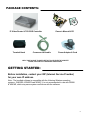
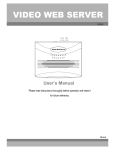
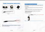
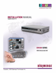
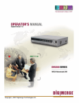
lP Video Router
& TLR-DVR Controller
Models: D4202
Installation / User Manual
Digimerge Technologies Inc.
CAUTION
RISK OF ELECTRIC SHOCK. DO NOT OPEN.
!
CAUTION: TO REDUCE THE RISK OF ELECTRIC SHOCK, DO NOT
REMOVE COVER (OR BACK). NO USER-SERVICEABLE PARTS
INSIDE. REFER SERVICING TO QUALIFIED SERVICE PERSONNEL.
WARNING : TO PREVENT FIRE OR SHOCK HAZARD, DO NOT
EXPOSE THE UNIT TO RAIN OR MOISTURE
The lightning flash with arrowhead symbol, within an equilateral
triangle, is intended to alert the user to the presence of un-insulated
"dangerous voltage" within the product's enclosure that may be of
sufficient magnitude to constitute a risk of electric shock to persons.
!
The exclamation point within an equilateral triangle is intended to
alert the user to the presence of important operating and
maintenance (servicing) instructions in the literature accompanying
the appliance.
This equipment has been tested and found to comply with the limits For a Class
B digital device, pursuant to Part 15 of the FCC Rules. These limits are designed
to provide reasonable protection against harmful interference in a residential
installation. This equipment generates, uses and can radiate radio frequency
energy and, if not installed and used in accordance with the ins truction, may
cause harmful interference to radio communications. However, there is no
guarantee that interference will not occur in a particular installation. If this
equipment does cause harmful interference to radio or television reception,
(which can be determined by turning the equipment off and on), the user is
encouraged to try to correct the interference by one or more of the following
measures:
• Increase the separation between the equipment and the camera, DVR and/or
monitor.
• Connect the equipment into an outlet on a circuit different from that to which
the DVR, monitor is connected.
Consult the dealer or an experienced radio or television technician for help.
-i-
CONTENTS:
GENERAL PRECAUTIONS--------------------------------------------------------------------------------------INTRODUCTION & FEATURES --------------------------------------------------------------------------------PACKAGE CONTENTS -------------------------------------------------------------------------------------------
1
2
3
Getting Started
IP ADDRESS --------------------------------------------------------------------------------------------------------REAR PANEL --------------------------------------------------------------------------------------------------------BOTTOM PANEL----------------------------------------------------------------------------------------------------HARDWARE CONNECTION AT SERVER SITE -------------------------------------------------------------
3
4
4
5
Static IP Setting
SOFTWARE INSTALLATION------------------------------------------------------------------------------------IP SETTING-----------------------------------------------------------------------------------------------------------Video Web Server SETTING-------------------------------------------------------------------------------------DVR REMOTE SETTING------------------------------------------------------------------------------------------PIN CONFIGURATION---------------------------------------------------------------------------------------------CONNECTING TO A PC VIA THE INTERNET----------------------------------------------------------------
6
8
9
11
12
13
Dynamic IP Setting
WHAT IS A DYNAMIC IP ADDRESS---------------------------------------------------------------------------SOFTWARE INSTALLATION------------------------------------------------------------------------------------SYSTEM RESET-----------------------------------------------------------------------------------------------------DDNS REGISTRATION FOR A DYNAMIC IP ADDRESS-------------------------------------------------CONNECTING THE PC TO A ROUTER / ROUTER LOGIN----------------------------------------------ROUTER SETTING-------------------------------------------------------------------------------------------------IP SETTING-----------------------------------------------------------------------------------------------------------VIDEO WEB SERVER SETTING--------------------------------------------------------------------------------DVR REMOTE SETTING------------------------------------------------------------------------------------------PIN CONFIGURATION---------------------------------------------------------------------------------------------CONNECT ALL DEVICES-----------------------------------------------------------------------------------------CONNECTING TO A PC VIA THE INTERNET---------------------------------------------------------------
14
14
14
14
16
19
21
22
24
24
25
25
Operation Guide
SOFTWARE OPERATION AT THE REMOTE SITE -------------------------------------------------------CONTROL PANEL & BASIC OPERATION ------------------------------------------------------------------PLAYBACK OPERATION ---------------------------------------------------------------------------------------ADVANCED SETTING -------------------------------------------------------------------------------------------FAQ’S ------------------------------------------------------------------------------------------------------------------SPECIFICATIONS ---------------------------------------------------------------------------------------------------APPENDIX#1 DVR CONTROL ----------------------------------------------------------------------------------APPENDIX#2 SENDING E-MAIL --------------------------------------------------------------------------------APPENDIX#3 SOFTWARE DOWNLOAD ---------------------------------------------------------------------REFERENCE NOTES-----------------------------------------------------------------------------------------------LIMITED WARRANTY ----------------------------------------------------------------------------------------------CARE & MAINTENANCE -------------------------------------------------------------------------------------------
-iii-
26
27
28
29
32
33
34
36
37
38
39
40
GENERAL PRECAUTIONS:
1.
2.
3.
4.
5.
6.
7.
8.
9.
10.
11.
12.
13.
14.
Read Instructions
All of the safety and operating instructions should
be read and understood before the product is used.
Retain Instructions
The safety and operating instructions should be
retained for future reference.
Heed Warnings
All warnings on the product and the instruction
manual should be followed.
Follow Instructions
All operating and use instructions should be followed
for optimal performance
Cleaning
Disconnect this video product from the power supply
before cleaning. Do not use liquid cleaners or aerosol
cleaners. Use a damp cloth for cleaning.
Attachments
Do not use attachments not recommended by the
video product manufacturer as they may cause
hazards.
Water and Moisture
Do not use this product near water - for example,
near a bathtub, wash bowl, kitchen sink, wet
basement, or near a swimming pool.
Accessories
Use this product only with a stand, tripod, bracket or
table recommended by the manufacturer or sold
with the product. Any mounting of the product
should follow the manufacturer’s instructions.
Ventilation
This product should never be placed near or over a
radiator or heat register. This product should not be
placed in a built-in installation, such as a book case
or rack, unless proper ventilation is provided or the
Manufacturer’s instructions have been adhered to.
Power Source
This product should be operated from the type of
Power source indicated by the marking label. If you
are not sure of the type of power supply to your
location, consult your product dealer or your local
Power company
Power Cord Protection
Power supply cords should not be routed so that
they are likely to be walked on or pinched by items
placed on or near them
Lightning
For added protection, unplug this product from its
outlet during a lightning storm. This will prevent
damage to the video product due to lightning and
power surges
Overloading
To avoid the risk of fire and electric shock, do not
plug this product into an over-loaded power supply.
Object and Liquid Entry
Never push objects into the openings of this product
as they may touch dangerous voltage points that
may result in fire or electric shock. Never spill
liquid of any kind on this product.
15.
16.
17.
18.
19.
20.
21.
22.
Servicing
Do not attempt to service this product yourself as
opening or removing covers may expose you to
voltage or other hazards. Refer all servicing to
qualified service personnel
Damage Requiring Service
Disconnect this product from the power supply
and refer servicing to qualified service
personnel under the following conditions:
a. When the power supply cord or plug is damaged
b. If objects have fallen into the product
c. If the product has been exposed to rain or liquids
d. If the product does not operate normally by
following the instruction manual. Adjust only
the controls that are covered in the instruction
manual as an improper adjustment may result
in damage and will often require extensive work
by a qualified service technician to restore
the product to its normal operation
e. If the product has been dropped or the cabinet
has been damaged
f. When the product displays a distinct change in
performance - this indicates a need for service
Replacement Parts
When replacement parts are required, be sure the
technician uses replacement parts specified by
the manufacturer. Unauthorized substitutions may
result in fire, electric shock, or other hazards.
Safety Check
Upon completion of any service to this product
ask the service technician to perform safety
checks to determine that the product is in
proper working condition.
Grounding or Polarization
This product is equipped with a three-wire
grounding-type plug, a plug having a third
(grounding) pin and will only fit into a
grounding-type power outlet. This is a safety
feature. If you are unable to insert the plug
into the outlet, contact your electrician to
replace your obsolete outlet. Do not defeat the
safety purpose of the grounding-type plug.
Power Lines
An outside antenna system should not be
located in the vicinity of overhead power lines
or other electric light or power circuits, or where
it can fall into such power lines or circuits.
When installing an outside antenna system,
extreme care should be taken to keep from
touching such power lines or circuits as contact
with them might be fatal.
Wall or Ceiling Mounting
The product should be mounted to a wall or ceiling
only as recommended by the manufacturer.
Heat
The product should be situated away from heat
such as radiators, heat registers, stoves, or other
products (including amplifiers) that produce heat.
-1-
INTRODUCTION & FEATURES:
Introduction
Thank you for purchasing the IP Video Router and TLR-DVR Controller. This is an internet
based digital video server capable of connecting up to 2 channels of video sources. The Video
Web Server turns a standalone recorder into an IP -enabled, networkable recorder. It broadcasts
compressed live video on-line (Intranet/Internet) via an Ethernet connection. It also enables DVR
series products and cameras to connect to the internet for remote monitoring or remote control.
This is a self-contained Web Server, meaning that you can access the camera server by
browsing the website over the internet using a standard browser (such as Explorer or Netscape).
The user friendly intuitive software allows for simple management, configuration and monitoring.
The system contains an image compression chipset that is capable of delivering standard JPEG
and real-time video into a limited network bandwidth
Features
• Compatible with most CCTV Products.
• Empowers all video output devices watching and controlling on the Internet or LAN.
• Auto Network Reconnection (ANR).
• Support alarm triggers recording & watch dog function.
• Support Dynamic IP address via a Router.
• Support 4 alarm inputs.
• Duplex function, record and playback simultaneously at client site.
• Auto e-mail warning system & images uploading function (to FTP site) that will remind you
if an external alarm was triggered.
• Intelligent non-stoppable recording function after ANR.
• Support Multi AP screens and HTTP display (IE browser).
• Unique video player.
-2-
PACKAGE CONTENTS:
IP Video Router & TLR-DVR Controller
Terminal block
Crossover LAN cable
Owner’s Manual & CD
Power Adapter & Cord
CHECK YOUR PACKAGE TO MAKE SURE THAT YOU RECEIVED THE COMPLETE
SYSTEM, INCLUDING THE COMPONENTS SHOWN ABOVE.
GETTING STARTED:
Before installation, contact your ISP (Internet Service Provider)
for your own IP address.
Note : The bundled software is compatible with the following Windows operating
systems : WIN2000, WIN2003 and WINXP. It is not recommended to use with WIN98
& WIN ME, which may cause system conflictions with the software.
-3-
CONTROL - REAR PANEL:
1
2
3
4
5
1. LAN
Connect the RJ45 standard pass through cable to the internet, or directly to a PC using
the crossover cable
2. ACT & LINK LED’s (Actual & Link)
When these LED’s are blinking it indicates that the network is in operation
3. VIDEO INPUT (BNC, 2 channels)
Connect to a video source, such as a camera or DVR video output.
4. ALARM I/O (optional for advanced applications)
Connect control devices, such as a DVR, Motion Sensors, external
alarm signal inputs, etc
5. POWER
Plug in the supplied power adaptor (12V ).
BOTTOM PANEL :
Bottom
3
RESET BUTTON (at the bottom of the Video Web Server)
Push this button for more than 5 seconds to reset the setting back to the default
setting.
-4-
HARDWARE CONNECTION AT SERVER SITE:
A . Connection Structure
NOTE: The RS-485 to control
the DVR is optional.
1. Connect the video output of the camera or DVR to the video input of the Video Web Server.
2. Connect the PC to the Video Web Server for IP setting.
3. Connect the Video Server to the ADSL or CABLE MODEM with a Static IP address.
4. Connect PC with Internet and remote control Video Web Server.
B . Connection Application
-5-
STEP 1: SOFTWARE INSTALLATION – STATIC IP SETTING:
1. Put the attached CD into the CD-ROM. The application program will install on your PC.
Note: The CD contains a self-running installation that automatically starts when the CD is
inserted. Follow the instructions for installation as indicated in the next few pages.
2. Press “Next”.
3. Choose the destination location and press “Next”.
-6-
4. Set the program shortcut setting and press “Next”.
5. Press “Next” to begin copying the files
6. After the installation, the following files listed below will appear in your assigned path or
file folder. There will be 6 files and 1 folder.
-7-
STEP 2: IP SETTING
1. Using the Crossover LAN cable connect the Video Web Server to the PC.
Note : In some operating environments, users might need the standard CAT5 cable.
RJ-45
POWER
2. Network setting for the PC. (The instruction is based on Win XP O/S. If your Operating
System is Win 2000 or Win 2003, the setup procedure is similar to that of Win XP O/S.)
Click
twice
3. Click on “Properties” for TCP/IP setup
-8-
4. Click on “INTERNET PROTOCOL (TCP/IP)” and then select “Properties” to setup
5. Click on “Use the following IP address” and set the IP address and subnet mask
NOTE :
1. Before changing the PC network setting,
please write down the original network
setting in order to recover the original
setting after the setup. (for static IP users)
2. The IP address should be
192.168.1.XXX. The setting of “XXX”
could be set from 1 to 254 Do not use 10
since 192.168.1.10 is the default IP ); the
subnet mask is 255.255.255.0.
STEP 3: VIDEO WEB SERVER SETTINGS
1. To configure the Server IP, please click
twice to enter the setup.
2. Key in the User Name, Password, and Server IP (The default setting for the User Name is
admin and the default Password is admin ; Server IP is 192.168.1.10, Port : 80). Click on
OK to connect.
-9-
3. When you see the control bar, this means that you have successfully logged into the
program on the Video Web Server. Click on “System Config” to set up.(NOTE: If you don’t
connect a camera or DVR to the Video Web Server, the only thing you will see is the control
bar.)
SYSTEM CONFIG
4. In the Peripheral setting, set the baud rate, ID and model that you want to remotely
control later. Press the “APPLY” to enable the change after the setting.
5. Click on “System Config” again. In the Network setting, set the server IP, gateway, net
mask and DNS provided from your local ISP (internet service provider). Press
“APPLY” to enable the change after the setting.
-10-
6. Disconnect the PC and Video Web Server, and link the static IP to the RJ -45 video web
server.
Static IP
STEP 4: DVR REMOTE SETTING
1. Connect the DVR and monitor.
2. In the “Remote” setting, set the baud rate and ID the same as the “Peripheral” setting
in the Video Web Server. Set the remote mode to RS-485 (see example below).
A. 1 / 4 CH DVR
(MENU)
TIMER
CAMERA
RECORD
ALARM
DWELL
REMOTE
SYSTEM
EVENT
(REMOTE)
REMOTE MODE : RS-485
BAUD RATE : 2400
ID : 001
B. 4 / 9 / 16 CH DMR
(MENU)
SEARCH
TIMER
RECORD
CAMERA
SYSTEM
EVENT
(SYSTEM)
:
:
REMOTE MODE : RS-485
BAUD RATE : 2400
REMOTE ID : 001
-11-
STEP 5: PIN CONFIGURATIONS
After the remote setting, connect the DVR, noting the following pins.
Video Web Server
PIN 1, 6. RS485-A, RS485-B
Use RS485-A & RS485-B serial communication signals to control digital units such as a
DVR.
PIN 4, 7, 8, 9. ALARM INPUT
Use PIN 4,7,8,9 to receive the alarm input and then trigger the Video Server to send Email to users for the auto e-mail warning system. (Alarm 1, 2 are for CH1; alarm 3, 4 are
for CH2)
PIN 5. GND
Ground
PIN 2, 3. NORMAL HIGH, NORMAL LOW
Use PIN 2 or 3 to trigger an external device.
Please see the picture below for a 1CH DVR connected to the Video Web Server.(See
Appendix #1)
RS485-A
Video Web Server
Pin 1
1 CH DVR
Pin 11
Pin 10
Pin 6
RS485-B
-12-
STEP 6: CONNECTING TO A PC VIA THE INTERNET
1. Change the PC network setting to the original setting and link the PC to the internet.
2. Click
twice to enter your User name & Password (Note : The default User
Name and Password are both “admin”), and the static IP, which you have set for the
Video Web Server in step 4.5. Then click OK to connect.
-13-
WHAT IS A DYNAMIC IP ADDRESS ?
A Dynamic IP Address is a n IP (Internet Protocol) address that changes each time you
connect to the internet. This cuts down on the number of IP addresses large consumer
providers need because not all of their customers are using the service at any given time. It
also cuts down on bandwidth usage by preventing consumers from hosting servers. Note: a
number of companies have started to offer services aimed at updating DNS for dynamically
connected clients.
STEP 1: SOFTWARE INSTALLATION – DYNAMIC IP SETTING:
Follow the same procedure as outlined on Page 6 & 7 for the Static IP Setting
STEP 2: SYSTEM RESET:
Before using the Video Web Server, please connect the power to the Video Web
Server and push the button under the unit for more than 5 seconds to reset the
setting. See the photo below
STEP 3: DDNS REGISTRATION FOR A DYNAMIC IP ADDRESS:
1. You must have a gateway router that supports DDNS (Dynamic Domain Network Service).
Please go to www.dlink.com or www.linksys .com for a list of available routers
2. To register for a dynamic IP address click on the free site “http://www.dyndns .org” and
click on “Account” (please look at the example below).
-14-
2. Click on “Create Account”
3. Register your information (Username, E-mail address & password). Click on
“Create Account” when the necessary information is completed
4. After registering your account, you will receive an e-mail, which contains instructions
to activate your account. If you do not follow these directions within 48 hours, you will
need to re-register your account.
5. Login your account.
-15-
6. Click on“Account” and “Add Host”
7. Users can set up their own DDNS HOST. For example, the user’s Host name is
“avtech.dyndns .org”. Click on “Add Host” to finish the setting. (NOTE : Some
routers don’t support some DDNS HOSTs)
digimerge
STEP 4: CONNECTING THE PC TO A ROUTER / ROUTER LOGIN:
NOTE : The following settings are different from router to route r. Please read the instructions
on your router thoroughly.
1. Connect the PC to the router using the LAN cable(LAN end)
POWER
-16-
2. Network setting for PC. (The instruction is based on Win XP O/S . If your O/S is Win
2000 or Win 2003, the setup procedure is similar to that of Win XP O/S.)
Click
twice
3. Click on “Properties” for TCP/IP setup
-17-
4. Click on “INTERNET PROTOCOL (TCP/IP)” and then select “Properties” to setup
5. Choose “Obtain an IP address automatically”
6. Enter the “Command Prompt”
-18-
7. In the setting window, enter “ ipconfig” , and write down the router’s gateway(e.g.
192.168.1.1)
8. Close the window above. Enter the IP address ( router’s gateway: 192.168.1.1 ) to
log in to the router from the Internet Explorer. Enter the login web page and key in
the router’s user name and password.
STEP 5: ROUTER SETTING (Please refer to your Router manual for the configuration)
NOTE : In the router setting, there are four steps to follow.
1. Dial setting
2. DHCP setting
3. Virtual server setting
4. DDNS setting
-19-
1. Click on “INTERNET PORT” and choose your WAN type (e.g. PPPoE). Enter your
“User Name” and “Password” to dial up the dynamic IP address. Press save
after you set up.
digimerge
2. Press “LOCAL PORT” and set “Start IP address” and “Number of IP address”. (For
example, if the IP address of your Video Web Server is 192.168.1.10, then 10 is
excluded from the setting range) Press save after you finish setting up.
3. In the “ADVANCED SETUP / Virtual Server”. Choose “By Port” and set the “Port
Number” to 80 for the Video Web Server. Set the “Local Server IP Address” to
192.168.1.10. (The default Video Web Server IP and port). Press add & save after you
set up.
-20-
4. In the “ADVANCED SETUP / Dynamic DNS”, key in the “DNS Account”, “User
Name” and “Password” that you applied in step 3. Press save after you set up.
digimerge
STEP 6 : IP SETTING
1. Connect the PC or Notebook to the Video Web Server using the crossover LAN cable.
Note: In some operating environments, users might need the standard CAT5 cable.
RJ-45 POWER
(MENU)
TIMER
CAMERA
RECORD
ALARM
DWELL
PIP
MOTION
DISPLAY
NETWORK
USER
SYSTEM
EVENT
PTZ
In the DVR Menu, select “Network”
(NETWORK)
IP ADDRESS
061.066.138.074
NET MASK
255.255.255.000
GATEWAY
061.066.138.073
DNS
168.095.001.001
PORT
00080
RESET DEFAULT
NO
The following 5 network settings should be entered.
(please see the example)
-21-
2. Network setting for PC. (The instruction is based on Win XP O/S . If your O/S is
Win 2000 or Win 2003, the setup procedure is similar to that on Win XP O/S.)
Click
twice
STEP 7: VIDEO WEB SERVER SETTING
1. To configure the Server IP, please click
twice to enter the setup.
2. Key in the User Name, Password, and IP address (The default setting for the User
Name and Password are both “admin”; IP address is 192.168.1.10, Port : 80). Click OK
to connect.
-22-
3. When you see the control bar, you have successfully logged into the program on the
Video Web Server. Click on “System Config” to set up.
SYSTEM CONFIG
4. In the Peripheral setting, set baud rate, ID and the model that want to remotely control
later. Press “APPLY” to enable the change after the setting.
5. Click on “System Config” again. In the Network setting, set the gateway the same as the
router’s gateway(192.168.1.1). Press “APPLY” to enable the change after the setting.
-23-
STEP 8: DVR REMOTE SETTING
1. Connect the DVR and monitor.
2. In the “Remote” setting, set the baud rate and ID the same as the “Peripheral” setting
on the video web server. Set the remote mode to RS-485.(see example below)
A. 1 / 4 CH DVR
(MENU)
TIMER
CAMERA
RECORD
ALARM
DWELL
REMOTE
SYSTEM
EVENT
B. 4 / 9 / 16 CH DMR
(MENU)
SEARCH
TIMER
RECORD
CAMERA
SYSTEM
EVENT
(REMOTE)
REMOTE MODE : RS-485
BAUD RATE : 2400
ID : 001
(SYSTEM)
:
:
REMOTE MODE : RS-485
BAUD RATE : 2400
REMOTE ID : 001
STEP 9: PIN CONFIGURATIONS
After the remote setting, connect the DVR, noting the following pins below
Pin 5
GND
N.O. Sensor
ALARM INPUT
Pin 4,7, 8 or 9
A normally open contact/sensor can be connected where
Pin 5 is Ground and Pin 4, 7, 8 and 9 is the Alarm Input
PIN 1, 6. RS485-A, RS485-B
Use the RS485-A & RS485-B serial communication signals to control digital units, such
as a DVR.
PIN 4, 7, 8, 9. ALARM INPUT
Use the PIN 4,7,8,9 to receive the alarm input and trigger the Video Server to send mail
to users for the a uto e-mail warning system. (Alarm1, 2 are for CH1; alarm3, 4 are for
CH2)
-24-
PIN 5. GND
Ground
PIN 2, 3. NORMAL HIGH, NORMAL LOW
Use PIN 2 or 3 to trigger an external device
Please see the picture below for a 1CH DVR connected to the Video Web Server.(See
Appendix #1)
RS485-A
Video Web Server
Pin 1
1 CH DVR
Pin 10
Pin 11
Pin 6
RS485-B
STEP 10: CONNECTING ALL DEVICES
ADSL modem
(WAN end)
DVR
STEP 11: CONNECTING TO A PC VIA THE INTERNET
1. Change PC network setting to the original setting and link PC to the internet.
2. Click
twice and enter your User name, Password and host on the Video
Web Server. (Note : If you did not change the “Account” , the User Name and
Password are both “admin”). Click OK to connect.
digimerge.dyndns.org
DDNS HOST
-25-
SOFTWARE OPERATION AT THE REMOTE SITE
Follow the steps below to connect to a remote site. (e.g. If you set up the server at
your office with one static ADSL, you can remotely watch the video anywhere, with a
networkable computer.)
Step 1: Click
twice to enter the Login setup (please refer to “software installation”)
Step 2: Key in “User Name” and “ Password”. (e.g. “User Name” and “Password” is
“dan”, and the IP address is 61.222.50.174). Click “OK” to establish the connection.
NOTE:
1.There are two ways to get the software,
one is via the attached CD, the other
is via the Video Web Server. (Refer to
APPENDIX#3)
2.You can press the “Address Book”
button to add a new IP into this
table or choose any login IP
address to access the Video Server.
3.This function is designed to store
a list of IP addresses which you
can control and manage.
Step 3: If you see the video screen, then you have successfully connecti ng to the server.
-26-
CONTROL PANEL AND BASIC OPERATION
A. Video Web Server control panel
1
2
3
4 5
6 7 8 9 10 11
B. Digital device control panel
12 13
1
2
3
4
5
6
1. Camera video inputs
2. Quad screen, 7-9-10-13-16 screen
3. Zoom, PIP, Select, Lock, Search, Enter
4. Stop, Record, Rewind, Fast Forward, Pause,
Slow, Play
5. Menu(Exit), Left, Right, Up, Down
14
1. Image transmission rate per second
6. Click on the arrow key to go to the “Video
Web Server Control Panel”
2. Video Channels
3. Data transmission rate
4. Connection/Disconnection
5. Resolution : VGA, QVGA
6. Image quality : High, Middle, Low
7. Image adjusting : Brightness/ Contrast/ Saturation
8. IP address (last 3 digits are displayed)
9. Snapshot : Press this button to automatically save the
image on your PC.
10. Record : Press this button to record the files & save them
on your PC
11. System setting
12. Number of online users
13. Window adjust ( right click for Full Screen)
NOTES
1.When you setup the video input from
the DVR, the screen will show the
operation interface, shown above.
2.Use the 16 CH DVR to explain the
operation (please refer to the
DVR user manual & APPENDIX#1 for
details)
3.After you press the record icon, there
will be a recorded file on your PC.
Each recording file can save up
to 6000 frames.
The recording file will be assigned
to the second file if it is more than
6000 frames.
If the HDD space is less than 200MB,
the program will stop recording.
14. Click on the arrow key to go to the “Digital Device Control
Panel”.
-27-
PLAYBACK OPERATION
You will find the recorded file on the PC. Click twice to playback.
1
2 3
4
5
6
7
8
9 10 11
12
1. On Screen Display
2. Snapshot
3. Stop
4. Pause
5. Slow (1/2, 1/4, 1/8)
6. PLAY
7. Fast
8. OSD show / hide
9. System setting (Path of snapshot,
text color, progress color, channel
color)
10. Back Video
11. Next Video
12. Playback controlling bar
-28-
ADVANCED SETTINGS
Click on “System Config” for advanced setting .
SYSTEM CONFIG
NETWORK
NOTE :
Apply-After all setting changes, press “apply” to
refresh the data in the Video Web Server.
Reboot-Press this button to restart the Video Web
Server.
To set up the network setting of the
Video Web Server, check with your
network administrator or Internet
Service Provider.
1. You can get all the information, Server
IP, Gateway, Net Mask & DNS, from your
ISP company.
2. Web Port : You can control the Video Web
server via this port.
3. Mac : The equipment’s physical address.
4. IP Type : This unit only supports Static
IP address, if you want to use Dynamic
IP, please obtain through a Router.
MAIL
When the alarm is triggered, the Video Web
Server will capture the instant picture and e-mail
the captured image to the assigned recipients.
1. You can get all the data from the ISP
company or by mailing to the server
supplier.(POP3/SMTP server)
2. You should set the mail list which you
want to send to when the alarm is
triggered.
3. If it is not necessary for you to verify
password and user’ s name, please
choose Verify as “No”.
4. Please refer to appendix#2 for more
details.
-29-
FTP
When the alarm is triggered, the video server
will capture the instant picture and upload the
captured image to the assigned FTP site.
1. You can get all the data from your MIS
department.
2. The default uploading port is No.21.
3. You can set the uploading directory
by yourself.
ACCOUNT
Set up the user’s account, password
(Max 5 accounts) and authority.
1. User’s level:
SUPERVISOR - controls all the functions
USER LEVEL - control advanced functions
GUEST LEVEL - control basic functions only
2. Life time : During this time period,
users are allowed to control the Video
Web Server.
PERIPHERAL
You can set up all the peripheral setting in this
Windows. (Refer to APPENDIX#1 for more
details)
Peripheral Control : Set up the video input
device. You can select the devices and
set up “Baud Rate & ID No.” to control the
equipment via the Video Web Server.
-30-
FILE PATH
You can modify the storing path for the
recording file and snapshot images .
TOOLBOX
Upgrade the firmware.
NOTE :
Do not reboot the Video Web Server while
it is upgrading the firmware.
1. Firmware Version : For the current
firmware version, you can click on the
“Find” button to get the latest firmware
from your PC. Press “Upgrade Firmware”
to upgrade it.
2.Turbo step: You can set the turbo step
when the turbo function is open.
ALARM
Set up the ALARM function. You can use it
to operate the “alarm trigger recording”
function.
1. Alarm : Enable or disable Alarm trigger
function.
2. Method : Two selections—Email or FTP.
3. Resolution : Image storing resolution for
Email or FTP function.
4. Alarm Duration : Alarm duration time.
5. Post Image : You can select how many
images you need to store when the alarm is
triggered.
6. Alarm record : Enable or disable “Alarm
trigger recording” function.
7. Alarm refresh : Clean the alarm
message “
” which is shown on the
screen.
-31-
ONLINE USER
Get online user’s information
1. Info refresh : Refresh the online users’
information
FAQ’S
1. With regards to direct connection to a PC, could I connect the video server with
remote PC without connecting it to the Internet ?
ANS: Yes, you can connect the Video server with remote PC using the Crossover
cable directly.
2. If I do not have any network in my office or house, could I use this system?
ANS: Yes, you could use this unit. You can connect the Video Server with PC or
notebook directly, and take the PC as a storage device. Save all video from
your cameras and display the Video record on the PC.
3. Can I use ISDN to connect the Video Server?
ANS: Our Video Server could be connected via ADSL or CABLE modem. It does not
support ISDN connection. However, if you have a router which supports ISDN,
RJ-45 and port forwarding function, it can be used with our Video Server.
4. What kind of frame rate are we expecting?
ANS: The frame rate = band width(Kbps) / 8 / image size(Kbytes)-->Daytime
QVGA(Low-6 Kbytes, Middle-9 Kbytes, High-12 Kbytes),
VGA(Low-24 Kbytes, Middle-36 Kbytes, High-48 Kbytes).
-32-
SPECIFICATIONS
Video Input
2 channels for analog and digital products, 1.0V p-p, Composite
BNC
Alarm Input
4 inputs
Watch Dog
Yes (this function keeps the Video Web Server working, and not
shut down)
RS-485 Port
Yes
Network Interface
Ethernet (10/100 Base-T)
Image Compression
JPEG
Video Adjustment
Brightness, Contrast, Saturation, Quality level adjustment
Protocols
TCP/IP, ICMP, FTP, HTTP
Hardware
CPU: 16 Bits RISC Processor, ROM: 512K Bytes Flash, RAM: 8M
Bytes SDRAM
One RJ-45 for 10/100 Mbps Ethernet, LED to indicate Link/ Actual
Status
GPIO with triggers for E-mail or FTP site
Max. # of remote accesses
6
Max. # of user accounts
10
Resolution
VGA: 640 x 480, QVGA: 32 0x 240
Performance
Up to 15/frames per second, 7.5 FPS/channel
Min. Bandwidth
64K
Trigger & Action
Triggered by GPIO Input, Action: E-mail images or images
uploading to the FTP sites specific account
Installation
Assign IP address
Security
Password Protection
Power
12V / 500mA
Because our products are subject to continuous improvement, Digimerge and its subsidiaries reserve the right to
modify product design and specifications without notice and without incurring any obligation. E&OE
-33-
APPENDIX #1 – DVR CONTROL
PIN CONFIGURATIONS FOR CONNECTION TO A 1CH DVR
DVR
Web Server
RS232-TX
GND
RS232-RX
RS485-B
VIDEO LOSS
RS485-A
SWITCH OUT
DISK FULL
ERROR OUT
ALARM RESET
REC STAR
ALARM INPUT
EXTERNAL ALARM NC
EXTERNAL ALARM COM
EXTERNAL ALARM NO
GND
ALARM INPUT2
ALARM INPUT1
ALARM INPUT3
NORMAL LOW
ALARM INPUT4
NORMAL HIGH
RS485-B
RS485-A
PIN CONFIGURATIONS FOR CONNECTION TO 4CH, 9CH
& 16CH DMR
DMR
EXTERNAL ALARM NO
EXTERNAL ALARM COM
RS485-A
RS485-B
RS232-TX
RS232-RX
ALARM INPUT 1
ALARM INPUT 2
ALARM INPUT 3
ALARM INPUT 4
Web Server
GND
ALARM INPUT 2
ALARM INPUT 1
ALARM INPUT 3
NORMAL LOW
ALARM INPUT 4
NORMAL HIGH
RS485-B
RS485-A
GND
-34-
2) Set the “Remote” function on the DVR.
NOTE : Remote mode : RS-485, Baud rate : selectable, ID : same as “Peripheral
Control” in the Video Web Server.
A. 1 / 4 CH DVR
(MENU)
TIMER
CAMERA
RECORD
ALARM
DWELL
REMOTE
SYSTEM
EVENT
(REMOTE)
REMOTE MODE:RS-485
BAUD RATE:selectable
ID:020
B. 4 / 9 / 16 CH DMR
(MENU)
SEARCH
TIMER
RECORD
CAMERA
SYSTEM
EVENT
(SYSTEM)
:
:
REMOTE MODE:RS-485
BAUD RATE:selectable
REMOTE ID:021
3) Set the “Peripheral Control” in the system configuration of the Video Web Server.
-35-
APPENDIX #2 – SENDING E-MAIL
1) Connect the Sub-D plug on the Video Web Server with the COM/NO ports of the
Sensor.
Video Web Server
Pin 5
GND
N.O. Sensor
ALARM INPUT
Pin 4,7, 8 or 9
A normally open contact/sensor can be connected where
Pin 5 is Ground and Pin 4, 7, 8 and 9 is the Alarm Input
2) Set the “Mail setting ” item in the system configure.
digimerge.eng
digimerge.eng
[email protected]
NOTE 1 : You can get all the data from the ISP ( Internet Service Provider) company or by
mailing to the server supplier (POP3/SMTP server).
NOTE 2 : You should set the mail list when the alarm is triggered.
NOTE 3 : When the alarm is triggered, you can find “
” message showed on the screen.
The AP will start recording automatically and you can get the email with the
snapshot image in your mailbox.
-36-
APPENDIX #3 – SOFTWARE DOWNLOAD
Step 1 : Please connect the PC to the Internet and key in the Video Web Server’s IP
address (ex : 61.222.50.160) in the browser. Then press E NTER.
Step 2 : Click on “Download Windows AP” to download the application program and save
“Setup.exe” in the HDD.
Step 3 : Click on “Setup.exe” twice to install the application program.
Step 4 Click on
twice to enter the Login setup and refer to “software installation”
for other operations.
-37-
REFEFENCE NOTES :
Static IP
1. In step 2.5 : Please make sure that your IP address is 192.168.1.XXX. The
setting of “XXX” could be set from 1 to 254, where 10 is excluded (The
default IP is 192.168.1.10 )
2. In step 4.4 : Please make sure that the Peripheral setting is the same as the setting
on the DVR, which you want to remotely control later.
3. In step 6.2 : The Server IP is the IP you set in step 4.5.
Dynamic IP
1. In step 3.7 : Some routers don’t support the DDNS HOST.
2. In step 4.1 : Please use the router’s LAN end to connect to the PC.
3. In step 4.8 : Please use the IE(Internet Explorer) browser to enter the router’s gateway.
4. In steps 5.1& 5.2 : Please make sure that you press “save’ after you finish the setting.
5. In step 5.3: Please make sure that you press “add” after you finish the setting
6. In step 5.4: Please make sure that you press “save’ after you finish the setting.
7. In step 7.4 : Please make sure that the Peripheral setting is the same as the setting on the
DVR, which you want to remotely control later.
8. In step 10 : Please use the router’s LAN end to connect the Video Web Server. Use the
WAN end to connect to the ADSL modem.
9. In step 11.2 : The Server IP is the DDNS HOST, which you set in step 5.4.
Important Note: You must have a gateway router that supports DDNS (Dynamic
Domain Network Service). Please go to www.dlink.com or www.linksys.com for a list
of available routers
You can connect directly to your Video Web Server from the Internet Explorer
Browser as long as you know your public IP address and you use Web Port 80
General Note: Do not use the IP addresses featured as an example in this document,
always consult your network administrator before assigning an IP address.
-38-
LIMITED WARRANTY
Warranty : Subject to the exclusions and limitations below, Digimerge warrants to the initial end-user purchaser that the
product will be free from defects in material and workmanship for a period of one year from the date of purchase.
For valid warranty claims made during the warranty period, upon proof of purchase, defective products will, at the election
of Digimerge, be repaired or replaced without charge. Any products repaired or replaced within the warranty period, shall
be warranted by Digimerge to the initial end-user purchaser for 90 days from the return shipment date, or the remainder of
the warranty term, whichever is longer, and if outside of the warranty period then for 90 days from the return shipment
date. Products and parts may be replaced with refurbished items, and the products and parts replaced become the property
of Digimerge. You are responsible for all shipping costs associated with the return of the defective products for warranty
service.
Exclusions and Limitations: Any of the following will void this warranty:
(i) installation or use of the product other than strictly in accordance with the instructions contained in the product’s instruction
manual;
(ii) if the product is subjected to operating conditions (including atmospheric, moisture and humidity conditions) outside of the
of the acceptable conditions specified in the product's instruction manual;
(iii) if the product is subjected to misuse or abuse;
(iv) if the product is subjected to electrical short circuits or transients, accident, fire, flood or Acts of God;
(v) adjustment, maintenance or repair of the product other than in accordance with Digimerge approved procedures; and
(vi) use of replacement parts other than those specified by Digimerge.
DIGIMERGE MAKES NO CLAIMS OR WARRANTIES OF ANY KIND WHATSOEVER REGARDING THE PRODUCT’S
ABILITY OR EFFECTIVENESS IN PREVENTING OR REDUCING THE RISK OF, OR DAMAGES RESULTING FROM, LOSS
OR THEFT OF PROPERTY OR PERSONAL INJURY.
THIS LIMITED WARRANTY IS IN LIEU OF ALL OTHER WARRANTIES, EXPRESS OR IMPLIED, INCLUDING, BUT NOT
LIMITED TO, ANY IMPLIED WARRANTY OF MERCHANTABILITY OR FITNESS FOR A PARTICULAR USE OR PURPOSE.
REPAIR OR REPLACEMENT AS PROVIDED UNDER THIS LIMITED WARRANTY IS THE EXCLUSIVE REMEDY OF THE
PURCHASER. DIGIMERGE SHALL IN NO EVENT BE LIABLE FOR ANY SPECIAL, INDIRECT, INCIDENTAL, PUNITIVE,
OR CONSEQUENTIAL DAMAGES OF ANY KIND OR CHARACTER, INCLUDING, WITHOUT LIMITATION, PERSONAL
INJURY, LOSS OF REVENUE OR PROFITS, FAILURE TO REALIZE SAVINGS OR OTHER BENEFITS, OR CLAIMS
AGAINST THE PURCHASER BY ANY THIRD PERSON, EVEN IF DIGIMERGE HAS BEEN ADVISED OF THE POSSIBILITY
OF SUCH DAMAGES.
No claims or statements regarding the product, whether written or verbal, by salespeople, retailers, dealers or distributors, that
are not contained in this limited warranty or in the owner's manual are authorized by Digimerge and do not modify or expand this
warranty.
Some countries, states, or provinces do not allow the exclusion or limitation of implied warranties or the limitation of incidental or
consequential damages for certain products supplied to consumers or the limitation of liability for personal injury. To the extent
that such restrictions on limitations apply to the products, the above limitations and exclusions may be limited in their application.
In that case, when the implied warranties are not allowed to be excluded in their entirety, they will be limited to the duration of the
applicable written warranty, and if damages may not be limited then the above limitations on damages apply, but only to the
greatest extent permitted by local law.
Warranty and Non-Warranty Service: Contact the dealer that sold you this product, during the warranty period if applicable, to
obtain service. Non-warranty service is subject to Digimerge's then current service terms and prices. If the dealer fails to
respond, cannot be reached or fails to provide you with the required service, you may obtain service directly from Digimerge by
calling our service department at (866) 344-4674. You must provide Digimerge with the defective product's model number, serial
number, date of purchase, sales or invoice number, proof that you were the original end-user purchaser for warranty work, and a
brief description of the problem. You must obtain a return authorization number from the service department and must mark the
number clearly on the shipping box. You must ship the item prepaid in appropriate packaging to the following address:
Digimerge Technologies Inc.,
Attention: Repair Department,
300 Alden Rd,
Markham, Ontario, Canada,
L3R 4C1
-39-
CARE AND MAINTENANCE:
Please follow these instructions to ensure proper care and maintenance
of this system
Keep your monitor and camera dry. If it gets wet, wipe it dry immediately.
Use and store your unit in normal temperature environment. Extreme
temperatures can shorten the life of the electronic devices.
Handle the monitor carefully. Dropping it can cause serious damage
to the unit.
Occasionally clean the unit with a damp cloth to keep it looking new.
Do not use harsh chemicals, cleaning solvents, or strong detergents
to clean the unit.
Keep the unit away from excessive dirt and dust. It can cause
premature wear of parts.
-40-
Digimerge Technologies Inc.
300 Alden Road
Markham Ontario
L3R 4C1
www.digimerge.com