1
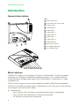
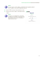
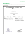
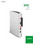
User guide
MAC
201
REF. 4449
AV-COFDM standalone modulator
Contents
4
General safety instructions
4
Types of notices
5
Basic safety instructions
6
Introduction
6
General description
6
Main features
7
General use of the unit
9
Unit installation and configuration
9
Installation
9
Power connection
10
Fast menu guide
11
Main menu
18
Advanced configuration of the unit
18
User interface via web browser
20
Maintenance
20
Unit care
20
Troubleshooting
21
Technical specifications
21
MAC 201 model
22
Warranty
22
Unit recycling
23
CE Certificate
General safety instructions/Types of notices
General safety instructions
JJ
Read all of this user manual carefully before plugging in the unit.
JJ
Always have these instructions to hand during installation.
JJ
Follow all of the instructions and safety notices regarding unit handling.
Types of notices
The meaning of the safety notices used in this manual are described below.
DANGER of DEATH OR INJURY
DANGER
This safety notice indicates a possible danger for the life and health of people.
Not following these instructions may lead to serious consequences to health and
may even cause fatal injuries.
RISK OF damage to the unit
ATTENTION
This safety notice indicates a possible dangerous situation. Not following these
instructions may lead to the unit being damaged.
Note
This type of notice is a note containing applicable advice and useful information
for optimum use of the unit.
HANDLING THE INSIDE OF THE UNIT IS FORBIDDEN
This notice forbids any work that may affect the working order of the unit or its
warranty.
DO NOT DISPOSE OF AS URBAN WASTE
This type of notice indicates that the unit must not be disposed of as unselected
urban waste.
4
General safety instructions/Basic safety instructions
Basic safety instructions
EN
DANGER of DEATH OR INJURY
JJ
Do not install the unit during an electrical storm. This could lead to electrostatic discharge from lightning.
JJ
Do not open the unit. There is a risk of electrostatic discharge.
DANGER
RISK OF damage to the unit
JJ
The unit must be appropriately ventilated. Install the unit in a dust-free
location. Do not place the unit in a location where the ventilation slots are
covered or blocked. Install the unit in a location with at least 20 cm around it
free of other objects.
JJ
Do not expose the unit to rain or moisture. Install the equipment in a dry
location with no infiltration or condensation of water. Should a liquid enter
the unit, disconnect it immediately from the mains.
JJ
Keep the unit away from flammable objects, candles and anything that may
cause a fire.
JJ
Connect the unit to an easily accessible power socket. In the event of an
emergency, it will then be possible to quickly unplug the unit.
JJ
Do not expose the unit to sources of heat (sun, heating, etc.).
ATTENTION
5
Introduction/General description
Introduction
General description
KEY
1 Mains connector
2 Front panel with cluster map
3 Display (LCD)
4 Control button
5 Video input 1
6 Audio input L 1
7 Audio input R 1
8 Video input 2
9 Audio input L 2
10 Audio input R 2
11 Ethernet connector
12 TV Loopthrough input
13 TV COFDM output
Main features
The MAC 201 model is an AV analogue TV signal to COFDM digital TV signal standalone
modulator unit. Suitable for individual residential installations, it is an ideal solution for
the distribution of analogue video signals with COFDM digital TV modulation in a single
standalone unit.
The AV1 and AV2 signals are also serially digitalised, coded in MPEG2 and modulated in
COFDM. The COFDM base band signal is modulated on an RF carrier that can be adjusted
at the output to the VHF and UHF bands.
JJ
Programming:
FF
6
User interface with LCD display and control button for basic configuration.
FF
User interface from web browser via Ethernet connection.
FF
All settings are automatically memorised.
Introduction/General use of the unit
JJ
FF
Reprogrammable as many times as required.
FF
Firmware updated via Ethernet connection with web browser.
EN
Signal processing:
FF
Double CVBS stereo video-audio input.
FF
Supported video standards: PAL/SECAM/NTSC.
FF
MPEG2 coding.
FF
RF DVB-T output, compatible with TDT.
FF
RF output, adjustable in VHF and UHF bands.
FF
Loopthrough for combination of additional RF TV signals.
JJ
Dimensions: 302 mm x 251 mm x 44 mm
JJ
Weight: 1.5 kg
The main characteristics of the MAC 201 model are described below.
MAC 201 model
Recommended for individual residential installations, consisting of two AV inputs and one
RF VHF/UHF output that delivers an output level of >80 dBμV.
JJ
JJ
JJ
Inputs:
FF
2 CVBS video inputs with stereo audio.
FF
Supported video standards: PAL/SECAM/NTSC
FF
RF loopthrough input.
Processing:
FF
Video: MPEG2.
FF
Audio: MPEG1 Layer II.
FF
Quality: DVD full D1.
FF
Generates the PSI tables: PAT, PMT, SDT, NIT, TDT and TOT.
FF
LCN processing.
Outputs:
FF
DVB-T output according to ETSI EN 300 744.
FF
Output MER > 38 dB (typical).
FF
Band aliasing < -45 dB.
FF
Output frequency bands: VHF + UHF.
FF
Average output level 80 dBμV.
General use of the unit
Below is described how to operate the unit using the control button and interpret the visual
indications on the LCD display. The program comprises a main menu made up of sub-menus that can be selected to modify the basic operation settings of the unit.
7
Introduction/General use of the unit
Visual indications on the LCD display
This symbol visually indicates the possibility of moving vertically.
Vertical button movement
In the menus and submenus, move the button up or down to browse
upwards and downwards position by position.
In the settings, move the button up or down to modify values position by
position.
NOTE
Keep the button pressed up or down to browse or to modify
values more quickly.
Horizontal button movement
In the menus, move the button to the left or the right to select and go
back position by position.
In the settings, move the button to the left or the right to select and go
back position by position.
NOTE
Keep the button pressed to the left or to the right to browse
more quickly.
Press button
In the menus, this selects the submenu.
In the submenus, this selects the setting.
In the settings, this selects the parameter value.
8
Unit installation and configuration/Installation
Unit installation and configuration
EN
The LCD display and the control button are sufficient for the basic settings of the unit.
Follow the steps indicated below to install the unit and configure the various parameters
accessible from the user interface on the LCD display.
Installation
RISK OF damage to the unit
ATTENTION
Mechanical handling of the unit while
it is switched on may lead to it being
damaged. Do not plug the unit into the
mains before or during installation.
1
1) Fit and tighten the bolts and plugs securing
the unit to the wall.
1+AV2
TV+AV
4
3
video 2
audio L2
audio R2
4) Connect the coaxial cable from the output to
the unit (connector F).
2
video 1
audio L1
audio R1
3) You can also connect the coaxial cable from
the RF loopthrough input (connector F).
TV (loopthrough)
2) Connect the AV1 and AV2 inputs in the respective RCA connectors.
ibution
to distrrk
netwo
Power connection
DANGER of DEATH OR INJURY
DANGER
Incorrect unit power connection may
cause an electric shock. Follow the
steps below for the electrical installation
of the unit.
1) Connect the earth cable.
2) Connect the power plug to the unit mains
connector.
3) Connect the power plug to the mains socket.
9
Unit installation and configuration/Fast menu guide
Fast menu guide
10
Unit installation and configuration/Main menu
Main menu
EN
Note
Over the following pages, the field locating and selection method is primarily
indicated by the “vertical button movement” and “press button” icons. However,
horizontal button movement can be used to locate and select fields, as indicated
in the General use of the unit.
1) After switching on the unit the initial display appears informing of the model, firmware version,
output frequency and information on alarms and
status:
FF
FF
Alarms:
ÌÌ
A:0 = no alarms
ÌÌ
A:X = alarms present
Status:
ÌÌ
S:X = status correct
ÌÌ
S:0 = status incorrect
2) Press the control button to access the main
menu.
General Settings
1) In the main menu, locate and select GENERAL.
IP configuration
note
The IP configuration affects the Ethernet interface.
note
To introduce a sequence of digits in the display move the control button vertically
to change the value of the current digit and horizontally to move between digits.
1) Locate and select the option IP.
a)
Locate and select the option DHCP to
activate (ON) or deactivate (OFF) dynamic
IP assigning. If this is deactivated, a static
IP must be configured.
11
Unit installation and configuration/Main menu
b) Locate and select the option IP address. Enter the 12-digit sequence
corresponding to the static IP address of
the unit.
c)
Locate and select the option IP mask.
Enter the 12-digit sequence corresponding
to the IP mask of the unit.
d) Locate and select the option Default
Gateway. Enter the 12-digit sequence
corresponding to the IP direction of the
LAN gateway.
Setting the time
2) Locate and select the option time-Date.
a)
Locate and select time- Dateto configure the time and date of the unit in the
format hh:mm yyyy-mm-dd.
b) Locate and select the option Time subzone to configure the reference time
zone.
Selecting the country
3) Locate and select the option Country to
select the reference country.
Setting the language
4) Locate and select the option Language to
establish the language of the menus on the
display: español, english, français.
Restoring factory settings
5) Locate and select the option Factory reset to restore the factory settings of the unit.
Select the option format to delete all the modifications entered in the configuration by the installer
or operator of the unit.
12
Unit installation and configuration/Main menu
Blocking the LCD and joystick
EN
6) Locate and select the option lock LCD to
block access to the configuration from the LCD
display and using the control button.
a)
Activate (ON) or deactivate (OFF) the
blocking option.
b) Establish a code to unlock the unit if this
option has been activated.
Setting the signals
note
The unit can switch the input signals; alter their brightness, contrast and saturation conditions; and adjust the output carrier in RF.
1) Locate and select the option Settings.
Configuring the input signals
1) Locate and select the option Input.
a)
Locate and select the option ch1:*****
bright to check the type of input signal,
the video and audio detection, and configure the brightness of the video signal (1
to 255).
b) Locate and select the option Cont1
saturation to configure the contrast
and saturation of video signal 1 (1 to 255).
c)
Locate and select the option inp audio
att 1 to configure the attenuation of audio
signal 1 (0 to 40)
d) Locate and select the option Sharpness
1 to configure the sharpness of video signal 1 (High, Medium soft or None).
e)
Locate and select the option Coding 1.
This configures the coding parameters:
MPEG2.
13
Unit installation and configuration/Main menu
f)
Locate and select the option Aspect
ratio 1. The possible aspect ratio values
are 1:1, 4:3 and 16:9.
note
If you keep pressing the control button down you will access the information and
configuration of the second input signal.
Configuration of the carrier services
2) Locate and select the option Services.
a)
Locate and select the option CH1 video
audio. Activate (ON) or deactivate (OFF)
the video and audio signals of the first
input.
b) Locate and select ch1 lcn. Configure the
LCN value of the signal.
c)
Locate and select CH1 Name. Assign a
name to the signal in CH1.
note
If you keep pressing the control button down you will access the information and
configuration of the second input signal.
Configuration of the output signal
note
To introduce a sequence of digits in the display move the control button vertically to change the value of the current digit and horizontally to move between
digits.
note
Position the cursor to the right of the current value and move the control button
vertically to increase or decrease the current value. Hold the control button up or
down to increase or decrease the current value more quickly.
3) Locate and select the option Output.
14
Unit installation and configuration/Main menu
a)
Locate and select the option Frequency. Configure the output frequency value
between 45 MHz and 865 MHz.
EN
b) Locate and select the option Attenuation. Select the output attenuation
between 0 and 47 dB.
c)
Locate and select the option OFDM
mode. Select the OFDM mode between
2k and 8k subcarriers.
d) Locate and select the option Bandwidth. Select the bandwidth between 6,
7 and 8 Mhz.
e)
Locate and select the option Guard
interval. Select the guard interval between 1/32, 1/16, 1/8 and 1/4 of symbol.
f)
Locate and select the option Constellation. Select the modulation constellation between 16qam and 64qam.
g) L
ocate and select the option Code rate.
Select the code rate between 1/2, 2/3, 3/4,
5/6 and 7/8.
Status of the unit
note
The unit lets you see its status in detail and the existence of active alarms in the
module.
1) Locate and indicate Status.
a)
Locate and indicate Status: ***. The
unit displays its status and alarms: OK /
Error.
15
Unit installation and configuration/Main menu
b) Locate and indicate output bitrate.
The unit displays the output data speed in
mbits/s.
c)
Locate and indicate null min act
max. The unit displays the volume of
null data packets in the output (minimum,
actual and maximum) as a percentage of
the total.
d) Locate and indicate Temperature. The
unit displays its temperature.
Unit information
1) Locate and indicate the option Module
info.
a)
Locate and indicate the option Model.
The unit displays its model and version.
b) Locate and indicate the option Serial
number. The unit displays its serial
number.
c)
Locate and indicate the option MAC. The
unit displays its MAC address.
d) Locate and indicate the option Version.
The unit displays its software version.
Unblocking the unit
The unit can be blocked from the web interface
preventing the user operating the display and the
control button to modify the configuration.
To unblock the unit:
1)
16
Locate and select lock code.
Unit installation and configuration/Main menu
2) Enter the unblocking code assigned by the unit
operator through the web interface.
EN
3) The unit displays the validity of the code.
note
The unit will remain unblocked until it is restarted or the operator deactivates the
block from the web interface.
To unblock the unit without the blocking code:
1) Locate and select Information.
2) Contact the supplier of the unit and provide the
serial number. The supplier of the unit will provide an unblocking code for the serial number
indicated.
17
Advanced configuration of the unit/User interface via web browser
Advanced configuration of the unit
User interface via web browser
The web interface allows you to fully configure the MAC 201 unit through an Ethernet connection and a web browser.
NOTE
To display the graphics provided in the unit configuration program correctly, we
recommend installing the web browser Mozilla Firefox 1.5 or higher (www.mozilla.
com) in the control PC.
NOTe
Cookies and Javascript must be enabled.
NOTE
Use a PC with an Ethernet network card and an Ethernet CAT-5E crossover cable.
1) Access the TCP/IP properties of the PC and configure the following parameters:
FF
IP address of the PC: 192.168.1.1
FF
Subnet mask: 255.255.255.0
2) Connect the PC to the LAN (RJ-45) port of the MAC 201 unit (see number 11 on the
diagram in the section General description).
NOTE
The initial process must be made in local mode, although later you will be able to
access the unit from any PC in the LAN.
NOTE
The Ethernet connector of the MAC 201 has two indicator lights:
JJ
The link is correct when the link LED (to the left of the Ethernet connector) is
lit.
JJ
There is activity in the link when the activity LED (to the right of the Ethernet
connector) is flashing.
3) Launch the web browser and enter the MAC 201 unit's IP address:
FF
Initial IP address: 192.168.1.6
NOTE
This initial IP address may be modified by the user.
18
Advanced configuration of the unit/User interface via web browser
NOTE
EN
The unit also has the IP address 10.254.254.254 assigned by default.
This IP address may not be modified by the user.
4) Press INTRO to access to the welcome screen.
5) Enter the user name “Admin” and the password
“admin”.
NOTE
The process of configuration and setting
via Ethernet connection is explained in the
“Web interface user manual” available at
http://www.ikusi.com.
19
Maintenance/Unit care
Maintenance
Unit care
HANDLING THE INSIDE OF THE UNIT IS FORBIDDEN
Do not dismantle or try to repair the unit, its accessories or its components. This
will render the warranty null and void.
JJ
Do not use the power cable if it is damaged.
JJ
To disconnect the power cable, pull carefully on the plug and not the cable.
JJ
To clean the panel and unit connections:
FF
Unplug the unit.
FF
Clean with a slightly damp, soft cloth.
FF
Allow to dry completely before use.
JJ
Do not spill liquid onto the unit.
JJ
Keep ventilation slots free of dust and any foreign bodies.
Troubleshooting
The most frequent problems arising during unit installation are indicated below. If you encounter any other type of problem, please contact the unit sales team.
Possible cause
Problem
Forgotten unlock code.
Nothing appears on LCD
display.
20
-
The power cable is not connected properly.J
What to do
Contact your supplier.
Check the power cable.
Technical specifications/MAC 201 model
Technical specifications
EN
MAC 201 model
Inputs
AV1 / AV2
Format
CVBS
Input level (video)
Vpp
Input impedance
Ω
Video standards
Yes / No
Vpp
Output
0.5 - 4.0
COFDM digital TV
COFDM standard
Bandwidths
75
PAL/SECAM/NTSC
Analogue / digital audio
Input level (audio)
0.7 - 1.4
DVB-T according to
ETSI EN 300 744
MHz
6/7/8
dB
38 (typical)
Central frequency
MHz
51 - 858
Level
dBμV
80
Number of carriers
MER
Output pitch attenuation
Impedance
2K / 8K
dB
1
Ω
75
Frequency pitch
kHz
1
Level adjustment
dB
-15
ppm
≤±30
Band aliasing
Frequency stability
dB
≤-50
Noise level (∆B = 8 MHz)
dBc
≤-70
Web user interface
Electric standard
LAN connector
Protocols
Ethernet 10BaseT
10/100 Mbps
RJ-45
HTTP / UDP
Operations
Mains voltage
230 - 240 V~
Consumption
0.45 A / 30 W
Operating temperature
Mains connector
0 to 45 ºC
IEC C8
21
Warranty/MAC 201 model
Warranty
Notwithstanding any complaints made to the direct vendor of the product, IKUSI offers unit
users a two-year warranty as of the invoice date, which shall become valid on presenting
the receipt of purchase.
During the warranty period, IKUSI is responsible for any faults arising due to material or
manufacturing defects and shall repair the receiver or replace it for another corresponding
to the state of technology at that time. The warranty does not cover any faults or defects
due to misuse or non-fulfilment of the information given in this installation manual.
All complaints other than those indicated are not included in the warranty. More specifically,
the warranty does not cover services provided by the authorised vendor (e.g. installation,
configuration or programme updates) or the repair of any damages or injuries caused to the
client or others as a result of the installation or of receiver operations.
Unit recycling
Recycling of electrical and electronic equipment
(Applicable in the European Union and in European countries with selective
waste collection systems.)
This symbol on your unit or its packaging indicates that this product cannot be
treated as general domestic waste and must be handed in at the corresponding
point of collection for electric and electronic equipment. By ensuring this product
is disposed of correctly you will help prevent negative consequences for the
environment and human health, which could otherwise be caused by inappropriate waste handling of this product. Recycling of materials helps preserve natural
resources. For more detailed information on the recycling of this product, please
contact your local council, your nearest collection point or the distributor from
whom you purchased the product.
22
CE Certificate/MAC 201 model
CE Certificate
EN
By reproducing the CE marking, IKUSI guarantees unit compliance with the corresponding
harmonised standards.
EC-Declaration of Conformity
marking
We, Manufacturer
IKUSI, Angel Iglesias, S.A.
Paseo Miramón, 170
E-20009 San Sebastián, Spain
declare that the product
AV-COFDM Autonomous Modulator
MAC-201
is in conformity with
EMC LVD
Council Directive 2004/108/CE
(EMC Directive)
and
Standards to which conformity is declared :
EN 50083-2 :2007
Cabled distribution systems for television and sound signals. Part 2: Electromagnetic compatibility for equipment.
Council Directive 2006/95/CE
(Low Voltage Directive)
Standards to which conformity is declared :
EN 60728-11 :2005
Cabled Distribution Systems for Television and
Sound Signals. Part 11: Safety Requirements.
EN 60065 :2003
Safety requirements for mains operated electronics
and related apparatus for household and similar general use.
Luis Rodríguez Navarrete
San Sebastián, March 2010
R&D Director
23
Ángel Iglesias, S.A.
Paseo Miramón, 170
20009 San Sebastián, Spain
Tel. +34 943 44 88 00
Fax +34 943 44 88 20
[email protected]
www.ikusi.com
120122A