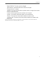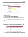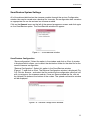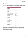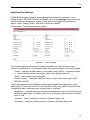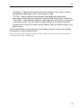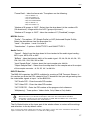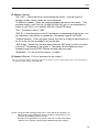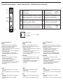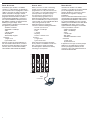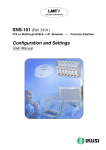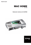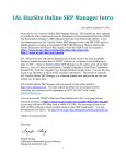
1
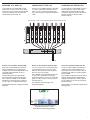
BNS-200
IPTV Streamer – Dual AV to IP multicast
Multicast streamer for IP broadband networks. Two channels of composite video with
stereo audio encoded for IP streaming over IP multicast networks.
Designed and manufactured by Messrs Ikusi of Spain. Sold and supported by
Teletechnique Beechmont in Queensland.
14 Jacaranda Court, BEECHMONT QLD 4211, Australia
Phone: +61-(0)7-3103-0750 - Fax: +61-(0)7-5604-1402
E-mail: [email protected]
Web: www.teletechnique.com - ABN 34 383 278 861
Data Sheet
V/A to IP Streaming Equipment
BNS200
REF. 5105
JJ
JJ
JJ
JJ
JJ
JJ
JJ
Double V/A to IP Stramer.
Output: 1 or 2 IP-encapsulated TV broadcasts with individualJ
multicast addresses.
Filtering of information contained in the MPEG-2 tables.
UDP and RTP transmission protocols.
Web interface for module configuration.
Alarm information SNMP agent.
SAP and SDP protocols to facilitate automatic programme selection in the
set-top box and to provide programme information to external servers.
BNS-200
(2x) VideoJ
(CVBS - PAL, SECAM, NTSC),
(2x) AudioJ
(ANALOGUE - Mono, ST/Dual)
Inputs
A/V inputs
Input Section (V/A)
Video input level
Video input impedance
Vpp
(2x) 0.7 – 1.4
Ω
(2x) 75
(2x) 0.5 – 4.0
Ω
(2x) > 600
PAL: 720 x 576, NTSC: 720 x 480
Vpp
Max video resolution
Audio input impedance
Audio input level

Yes
SNMP support - traps
Codificación MPEG
Video coding
MPEG-2 MP&ML, MPEG-4 ASP Audio coding
MPEG-1 Layer II
Ethernet switch
Output Section (IP)
Standard
Bit rate
IP NET
IEEE 802.3 10/100 Base T
Mbps
up to 100
Transmission protocols
UDP/RTP
No. of simultaneous streams
2
Multicast
Yes
J
Connectors
Video connection
(2x) female RCA
Audio connection
(4x) female RCA
DC connection
— Ejemplo de cabecera mixta BNS/SNS para cuatro fuentes locales audio/vídeo y seis transpondedores TV satélite digital. Contiene 2 BNS-200,
6 SNS-102 y 1 alimentador CFP-500, instalados
todos ellos en 1 base-soporte BAS-900. Esta
estación puede suministrar a la red IP hasta 48
cadenas TV (8 cadenas por streamer SNS) más
4 emisiones locales TV (2 de sonido mono y 2
sonido estéreo).
banana socket
Configuration
RS 232/DB-9
Ethernet output
RJ-45
J
General
Supply voltage
Vdc
Consumption
mA
Indicator LEDs
+12
640
ON - STATUS - LINK - ACT
Operating temperature
°C
0 – +45
Dimensions
mm
230 x 195 x 32
The module is packed with:
- 1 DC plug bridge, 53 mm length, for connection of +12 Vdc voltage.
Ángel Iglesias, S.A.
Paseo Miramón, 170
20009 San Sebastián, Spain
Tel. +34 943 44 88 00
Fax +34 943 44 88 20
[email protected]
www.ikusi.com
Television on IP Networks
BNS-200 (Ref. 5105)
Double A/V ➞ IP Streamer
Configuration and Settings
User Manual
EN
Configuration and Setting of the BNS-200 Streamer Module
User Manual
November 2008
Revision A
IKUSI - Ángel Iglesias, S.A.
Paseo Miramón, 170
20009 San Sebastián
SPAIN
Tel.: +34 943 44 88 00
Fax: +34 943 44 88 11
www.ikusi.com
CONTENTS
Introduction ............................................................................................................................. 4
This Manual ................................................................................................................. 4
Product Description ...................................................................................................... 4
Chapter One - Configuration of the BNS-200 Streamer ......................................................... 5
Configuration ........................................................................................................... 6-10
Save/Restore Configuration ....................................................................................... 11
General Report .......................................................................................................... 12
Chapter Two - BNS-200 Streamer Settings .......................................................................... 13
Input Settings ........................................................................................................ 14/15
Coding Settings ..................................................................................................... 16/17
Output Settings ..................................................................................................... 18/19
SAP/SDP Channel Settings ....................................................................................... 20
SNMP Configuration ............................................................................................. 21/22
Chapter Three - BNS-200 Streamer Status Information ....................................................... 23
Status Information ...................................................................................................... 24
Chapter Four - BNS-200 Streamer Reports .......................................................................... 25
Output Streams .......................................................................................................... 26
System Logs .............................................................................................................. 27
3
Introduction
This Manual
This manual describes the configuration and settings programme for the BNS-200 Streamer Module.
It is the second part of the user documentation for said module, the first part of which is the Installation
and Access manual supplied in paper format.
Product Description
BNS-200 streamers are A/V to IP gateways designed to broadcast in multicast on an IP network the TV
broadcasts issued from video and audio local sources. The IP streams can be viewed using an IPTV settop box or a software video player.
BNS-200 modules have an IKUSI ClassA mechanical format. As such, they are fixed to BAS-700 / BAS-900
baseplates or to an SMR-601 rack frame, and are +12 VDC powered from a CFP module.
Characteristics
●
●
●
●
●
Output: 1 or 2 IP-encapsulated TV broadcasts with individual multicast addresses.
UDP & RTP transmission protocols.
Web interface for configuration and setting.
Alarm information SNMP agent.
SAP & SDP protocols that facilitate automatic service selection on the user's STB and provide information to external servers.
ADVANCED
Configurable QoS marking
Configurable Time To Live
When the connection is established between the BNS-200 streamer and the control PC, the programme
access screen appears:
Programme Access Screen
Once the desired programme language has been chosen [ English (en), Spanish (es), French (fr) ],
enter the password and click on OK.
Note: The default password — admin — can (and must) be changed as explained on page 9.
4
Chapter One - Configuration of the BNS-200 Streamer
In this Chapter
●
Configuration
●
Save/Restore
●
General Report
5
Configuration
General Configuration
Initial program screen
The first screen that appears
when the programme is
accessed contains the "Output"
window, which gives information
on the IP streams that have
been created on the module and
which may or may not be
incorporated into the output data
stream.
On the left of this screen are the
menus that access all of the
programme's functionalities.
Figure 1.1 - Initial programme screen
Click on the General menu on the left of the screen to display a dropdown list
containing the 3 options: Configuration, Save/Restore and General Report.
Click on Configuration. The Configuration window will appear :
Figure 1.2 - Identification card of the Configuration window.
Identification
The identification card (Figure 1.2) provides basic data on the BNS-200 streamer. The
different card fields are completed as follows:
6
Configuration
"Model": BNS-200. This data cannot be changed.
"Serial Number": Informational data which cannot be changed.
"Firmware Version": As above.
"Identifier": Any name that the installer or operator wishes to assign to the streamer
module can be entered here.
"Location": Enter the postcode of the installation site if required.
"Installer": The installer's identification details can be entered here.
"Contact": Then enter their contact details (telephone number, email).
"Installation date": The date on which the streamer module was installed can be
entered here.
Click on the Save button at the bottom of the window to store the information on the streamer module, this
information is then shown each time the module is accessed.
7
Configuration
Network
Click on the Network tab to configure the streamer's ethernet connection parameters.
The following card is displayed:
Figure 1.3 - Network card of the Configuration window.
"Use DHCP to get IP address": If this box is checked, the BNS-200 module will use
the DHCP protocol for assigning dynamic IP addresses. Consequently, no data
needs to be entered in the next five fields on the tab.
If the administrator of the network on which the BNS headend is installed assigns
static IP addresses, the box will not be checked and the following fields will need to
be filled in.
WARNING: If this option is activated, the IP address assigned to the streamer can
only be known by consulting the DHCP server management system.
"IP Address": Enter the IP address that you wish to assign to the streamer. This
address must fall within the range of local network addresses.
"Network mask": Enter the local network mask.
"Default gateway": Enter the IP address of this gateway. This information is only
required if you want the streamer to access Internet.
"Primary DNS server": Enter the primary server's IP address. Equally, this
information is only required if you want the streamer to access Internet.
"Secondary DNS server": Enter the same information for the secondary server.
"MAC Address": The physical address of the streamer's ethernet network card is
displayed automatically.
Once you have filled in all of the required information, click on Modify Network Configuration. If, at the last moment,
you decide to keep the current settings, click on Restore.
8
Configuration
Password
If you want to change the current access password, click on the Password tab. The
following card is displayed:
Figure 1.4 - Password card of the Configuration window.
"Current password": Enter the current password.
"New password": Enter the new password which will be required to access the
program the next time.
"Confirm new password": Re-enter the new password.
Once you have entered the required information, click on Modify so that the streamer adopts the new access
password. If, at the last moment, you decide to keep the previous password, click on Cancel.
!
Note
If you do not know the old password, i.e. the password used to access the current configuration
session, you must perform a Password Reset as explained in the Installation and Access manual.
Following this reset, the program password will be the default password: admin.
IMPORTANT: When you perform a password reset, the IP address assigned to the streamer on the
Network card (previous page) automatically changes to the default setting: http:// 92.168.1.4.
Shutdown
If you need to reboot the streamer for any reason, click on the Shutdown tab. The
following card is displayed:
Figure 1.5 - Shutdown card of the Configuration window.
Click on Reboot. A reset is then performed after which the Output Streams screen
will appear, this is the presentation screen of the programme.
9
Configuration
Update Firmware
If you wish to update the streamer's firmware, click on the Update Firmware tab. The
card displayed (Figure 1.6) shows the firmware version that the streamer has at the
present time.
(The firmware is software stored in the module which is responsible for its basic operation).
Figure 1.6 - Update Firmware card of the Configuration window.
WARNING: The firmware update file will have been previously stored on the PC hard drive. (You can
download it from http://www.ikusi.com).
Click on Browse... and select the firmware update file from the hard drive. When the file
name is in the box, click on Start. The new firmware will be installed on the streamer
and then its name will appear in the card replacing the one of the file before.
10
Save/Restore
Save/Restore System Settings
All of the data established on the streamer module through the various Configuration
window tabs can be saved onto a backup file. Inversely, the configuration data saved on
an appropriate file can be restored on streamer module.
Click on the General menu on the left of the general programme screen and click again
on the Save/Restore option. The Save/Restore window will appear:
Figure 1.7 - Save/Restore window
Save/Restore Configuration
"Save configuration": Select the option in the window and click on Start. A window
is displayed which allows you to select the destination folder for the data file for the
current streamer configuration.
"Restore Configuration": Select this option in the Save/Restore window
(Figure 1.7) and click on Start. The Restore Configuration window is displayed (Fig.
1.8) Click on Browse... and select the file containing the configuration data that you
wish to restore on the streamer module. Once you have selected the file, click on
the Upload File button at the bottom of the screen. The upload confirmation window
will be displayed.
Figure 1.8 - Restore Configuration Window
11
General Report
General Report
Click on the General menu on the left of the general programme screen and click again
on the General Report option. The General Report window is displayed:
Figure 1.9 - General Report window
This window provides complete information on the BNS-200 module, not only regarding
the configuration described in the previous pages, but also in relation to the current
settings parameter values and operational status.
The information contained in this window can be printed by clicking on the Print page
button at the bottom of the screen.
12
Chapter Two - BNS-200 Streamer Settings
In this Chapter
●
Input Section Settings
●
Coding Section Settings
●
Output Section Settings
●
SAP/SDP Channel Settings
●
SNMP Configuration
13
Input
Input Section Settings
The BNS-200 module settings are grouped into five sections or categories: Input,
Coding, Output, SAP/SDP Channel and SNMP. Click on the Settings menu on the left
side of the general programme screen. A drop down list is displayed offering four
options: Input, Coding, Output, SAP/SDP Channel and SNMP.
Click on Input. The Input window will appear:
Figure 2.1 - Input window
This window presents two identical sections related to each one of the two input
sections of the BNS-200. The window informs first about existence of A/V input signals:
"Video" : Indicates whether there is or not video signal (CVBS — composite video).
A ✓ mark indicates existence of signal, and a cross ✖ does absence.
"Audio" : Idem audio signal (analogue).
"Colour System" : Informates about the colour system of the video signal (PAL,
SECAM or NTSC).
The window presents below different setting fields related to the digitalisation of the
video signal. The two last ones (TV Filter and Field Order) only appear if the Advanced
Configuration box at the upper part of the window is checked.
"Brightness" : Increment buttons for setting the brightness you want to confer to the
digitalized video signal. The box at right shows a reference figure whose by default
value is 128.
"Contrast" : Idem for setting the contrast. By default figure: 66.
"Saturation" : Idem for setting the colour saturation. By default figure : 63.
14
Input
"Sharpness" : Select from the drop down list the sharpness you want to confer to
the digitalized video signal: None, Low, Medium or High.
"TV Filter" : Idem the type of video filtering in the digitalisation processing:
Deactivated, Spatial NR (noise reduction), Temporal NR, Noise Filter, Comb Filter.
"Field Order" : Idem the field of the input video signal that will be the first (dominant)
in the output stream. The Top Field First option selects as first field the one that
includes the first line of the screen, and the Bottom Field First option selects as first
field the other.
The By Default button at the lower part of the window allows to restore all the settings
and selections to the by default values.
Once you have done all the settings and selections in the two sections of the window, click on the Save button to
conclude the Input settings of the BNS-200.
15
Input
Coding Settings
Click on the Settings menu on the left of the general programme screen and then click
on Coding. The Coding window will appear :
Figure 2.2 - Coding window
This window has two identical cards, Input 1 and input 2, related to the two input
sections of the BNS-200. Each card has 4 sections —Video, MPEG4, Audio and DVBTS—, where one can configure the MPEG coding of the input video/audio signals and
the related DVB transport stream.
Video Section :
"Coding" : Select from the drop down list the coding standard: MPEG2 or MPEG4
ASP.
"Rate Control Mode" : Idem the control mode of the stream bitrate: Unlimited
BitRate or Limited BitRate. When selecting "unlimited", the Average BitRate field
appears below. Idem "limited", the Max BitRate field.
"Average BitRate" : Slide icon for setting the average output bitrate of the MPEG
coder. The highest and lowest values of the operating bitrate will be able to amount
to +50% and -50% respectively of the entered value.
"Max BitRate" : The entered value will not be surpassed at any time.
"Resolution" : Select from the drop down list the resolution for the digitalized video
signal. The available options are the following:
- CIF 176x144
- 2CIF 352x288
- HalfD1 NTSC 352x480 ó PAL/SECAM 352x576
- 4CIF NTSC 704x480 ó PAL/SECAM 704x576
- D1 NTSC 720x480 ó PAL/SECAM 720x576
"Aspect Ratio" : Select from the drop down list the aspect ratio for the digitalized
video signal: 1:1, 4:3 or 16:9.
16
Input
"Frame Rate" : Idem the frame rate. The options are the following:
- 12fps PAL MPEG4 only
- 15fps NTSC MPEG4 only
- 25fps PAL MPEG2/MPEG4
- 30fps NTSC MPEG2/MPEG4
- 50fps PAL MPEG2 only
- 60fps NTSC MPEG2 only
"Number of B images in GOP" : Select from the drop down list the number of B
("Bi-directional") images within the GOP ("group of pictures").
"Number of P images in GOP" : Idem the number of P ("Predicted") images.
MPEG4 Section :
"Profile" : Two options : SP (Simple Profile) or ASP (Advanced Simple Profile).
Select the desired one from the drop down list.
"Level" : Six options : Level 0 to Level 5.
"Quantization" : 2 options: QUANTTYPE 0 and QUANTTYPE 1.
Audio Section :
"Format" : Select from the drop down list the standard of the audio signal coding :
MP1 Layer, MP3, AC3 or AAC.
"BitRate" : Idem the bitrate in kbit/s of the audio signal : 32, 48, 56, 64, 80, 96, 112,
128, 160, 192, 224, 256, 320 or 384.
"Input Sample Rate" : Informs about the input sample rate: 48 kHz.
"Output Sample Rate" : Select from the drop down list the sample rate at the output
of the sample converter : 8, 24, 32, 44.1 or 48 kHz.
DVB-TS Section :
The BNS-200 organizes the MPEG multiplex for creating a DVB Transport Stream. In
this section you enter the PIDs related to the TV broadcast that you are generating from
the video/audio signals at Input 1 of the BNS-200 :
"OUT Audio PID" : Enter the audio PID number.
"OUT Video PID" : Enter the video PID number.
"OUT PCR PID" : Enter the PID number of the program clock reference.
"Multiplexing" : Three options: Video+Audio, Only Video or Only Audio.
!
Note
The three PID numbers must have 4 figures and be different. At the same time they must be
different from those you will enter in the Input 2 card for the other TV broadcast that will be
generated in a similar way. The values by default are 4096, 4097 and 4098 for the "TV broadcast
1", and 4111, 4113 and 4114 for the "TV broadcast 2".
The By Default button at the lower part of the window allows to restore all the settings
and selections to the by default values.
Once you have done all the settings and selections of the Input 1 section, click on the Save button. Next fill in the
Input 2 card and click on its Save button to conclude the Coding settings.
17
Output
Output Section Settings
Click on the Settings menu on the left of the general programme screen and then click
on Output. The Output window will appear :
Figure 2.3 - Output window
In this window you configure as IP streams the two TV broadcasts (or only one, if the
BNS-200 operates with a unique A/V signal source) included in the DVB transport
stream that you have created through the Input and Coding options of the Settings
menu.
The window presents 3 sections for general and particular configurations of the two
sections of the BNS-200.
General Configuration Section :
"Protocol": The drop down menu offers two options : UDP and UDP/RTP. UDP is a
transport protocol which is not connection oriented and is particularly useful for
streaming. UDP/RTP adds extra data fields so that the data flow is served at the
correct speed for its projection in real time.
"Time To Live": Is a parameter used to restrict the stream multicasting range. A
number between 1 and 255 is entered in this box. Each time that an IP stream
passes through a router, the TTL is reduced by one unit. The stream will be
rejected by any router when the TTL value is reduced to zero.
"QoS": Quality of Service. The drop down list offers five differentiated service
options or Diffserv. These options relate to the priority that you wish to assign to the
streaming packets on their routes through switches or routers that are QoS
management capable:
1.
2.
3.
4.
5.
Maximum priority
High priority video
Low priority video
Video and voice
Best effort (best effort made to correctly deliver the video data and the associated audio data)
"IP Encapsulating Mode" : 2 options: Two Streams (one for each TV broadcast) or
One Stream (the two broadcasts are combined in a unique IP stream 1).
An additional field informs about the total bandwidth of the output IP transport stream.
18
Output
IP Stream 1 Section :
"ON / OFF" : Check the box for incorporating the stream 1 into the output IP
transport stream. Leave it blank for no incorporation.
"IP Multicast Address": Enter the multicast address desired for the stream 1. The
available range is from 224.0.0.0 to 239.255.255.255, but it is recommended to
reduce it from 224.0.1.0 to 238.255.255.255. See NOTE below.
"Port": The default value is 1234.
"SAP ID": Is the name given to the TV broadcast corresponding to the stream 1 on
the subscriber's set-top box or reproducer, if the device supports SAP/SDP.
"Channel Number" : Enter the order number you want to assign to the broadcast in
the list of the services provided by the set-top box.
"SAP Group" : Select from the drop down menu the SAP group to which you want
to link the TV broadcast of the stream 1. The group will have been previously
created through the SAP/SDP Channel window (see next page).
"Bandwidth" : It is the one of the stream 1, in Mbps.
IP Stream 2 Section : Fill in as described for the stream 1.
Once you have done all the settings and selections in the three sections of the window, click on the Save button to
conclude the Output settings of the BNS-200.
NOTE : Range 224.0.0.0 through 224.0.0.255 is reserved for local purposes (as
administrative and maintenance tasks). Datagrams destined to this use
are never forwarded by multicast routers.
Similarly, the range 239.0.0.0 to 239.255.255.255 has been reserved for
"administrative scoping" (administratively defined topological regions).
19
SAP/SDP Channel
SAP/SDP Channel Settings
Click on the Settings menu on the left of the general programme screen and click
again on the SAP/SDP Channel option. The SAP/SDP Channel window will appear:
Figure 2.4 - SAP/SDP Channel window
This menu option is used to configure the announcement and service description SAP/
SDP channel. SAP and SDP are two protocols for creating an EPG type program guide.
"SAP Activated": Check the box if you wish to transmit the program guide.
"SAP IP address": This data cannot be changed. It is the IP address assigned to
the streamer module on the Network tab in the Configuration window (page 8).
"Username": The name entered will be transmitted on the SAP/SDP channel.
"Group": As above.
"Time interval between SAP announcements": Introduce the time interval, in
seconds, at which the transmitted programmes guide will refresh.
Click on Save to save the SAP/SDP channel configuration data.
20
SNMP
SNMP Configuration
Click on the Settings menu on the left of the general programme screen and click
again on the SNMP option. The SNMP Agent window will appear:
Figure 2.5 - SNMP Agent window
This window is used to configure the notification of determined traps the SNMP manager (management station). It has two sections: Configuration and Traps.
Configuration Section :
"MIB" : Click on Download to download the MIB of the BNS-200 streamer.
"SNMP Agent" : Tick the box if you want to activate the SNMP agent implemented
in the streamer module.
"SNMP Manager IP" : Enter the IP address of the manager.
"Community" : Enter the desired name for the group formed by the streamers and
power supplies of the present BNS headend, and by the manager.
"Activate CFP-702" : Tick the box in the case the streamer module is linked to a
CFP-702 power supply and you want to integrate this into the management system.
(See Fig. 2.6 on next page).
"Identify CFP-702" : Enter a name for the CFP-702 linked to the present streamer
module.
"Minimum Alarm Duration" : Enter the minimum duration in seconds of an alarm
event so that it be considered as such by the SNMP manager.
"Send Traps Continuously" : Tick the box if you want that to an alarm event the
related trap be sent repeatedly to the manager. If this box is ticked, the two next
ones are disabled.
"Trap Sendings" : Enter the times to an alarm event you want to send the
corresponding trap to the manager.
"Time between Sendings" : It is related to the box before. Enter the time in seconds
between the trap sendings.
"Time Sending Traps with ACK" : It is applicable to traps with ACK enabled. Enter
the maximum time in seconds to an alarm event the trap will be being sent
continuously until having an acknowledgement from the manager.
21
SNMP
Traps Section :
You select here the BNS-200's parameters whose alarm status generate traps, either
with or without acknowledgement.
"Hardware" : Tick the box for sending an alarm trap when there be an anomaly in
the streamer's circuitry. If you want to receive an acknowledgement from the SNMP
manager, tick also the Enable ACK box at right.
"Video at Input 1" : Idem when video signal at input 1 disappears, or when it return
being off.
"Audio at Input 1" : Idem audio signal at input 1.
"Video at Input 2" : Idem video signal at input 2.
"Audio at Input 2" : Idem audio signal at input 1.
"Coding" : Tick the box for sending an alarm trap when the MPEG coding
processing is not correct.
"ColdStart" : Idem when there be a Cold Start (the power is turned off then back
on).
"WarmStart" : Idem when the module is rebooted (through the Shutdown card of
the Configuration window, see page 9).
"CFP Temperature" : It is applicable only if the streamer module is linked to a CFP702 power supply, with the object of incorporating this to the SNMP system. It is
related to the internal temperature of the power supply. Tick the box so that the
alarm trap be transmitted when this temperature exceedes the established limits.
"CFP Voltage" : Idem in relation to the +12V output voltage of the power supply.
"Status" : Tick the box for sending a "summary" trap with the current status of the
most outstanding parameters.
"Time between Sendings" : This box is enabled only if you ticked the previous one.
Enter the desired time in seconds to pass between "summary" trap sendings.
QPSK IN
QPSK IN
QPSK IN
QPSK IN
QPSK IN
V/A 1
V/A 2
VIDEO
VIDEO
M
O
N
O
+VLNB
+VLNB
CAM
CONTROL
+VLNB
CAM
CONTROL
+VLNB
CAM
CONTROL
V/A 1
V/A 2
VIDEO
VIDEO
M
O
N
O
M
O
N
O
AUDIO L
AUDIO L
AUDIO L
AUDIO L
AUDIO R
AUDIO R
AUDIO R
AUDIO R
+VLNB
CAM
CONTROL
M
O
N
O
CAM
CONTROL
CONTROL
CONTROL
CONTROL
CONTROL
CFP-702
SYNC
STATUS
SYNC
STATUS
+12V
POWER
SYNC
STATUS
+12V
SYNC
STATUS
+12V
SYNC
STATUS
+12V
SYNC
STATUS
+12V
SYNC
STATUS
+12V
+12V
CFP-702
POWER
+24V
+24V
monitoring
jumper
+18V
300 mA
(22 KHz)
SNS-101
SNS-101
SNS-101
SNS-101
SNS-101
BNS-200
BNS-200
DVB-S Þ IPTV
STREAMER
DVB-S Þ IPTV
STREAMER
DVB-S Þ IPTV
STREAMER
DVB-S Þ IPTV
STREAMER
DVB-S Þ IPTV
STREAMER
DOUBLE
V/A Þ IPTV STREAMER
DOUBLE
V/A Þ IPTV STREAMER
Ref. 5101
Ref. 5101
Ref. 5101
Ref. 5101
Ref. 5101
Ref. 5105
+18V
Ref. 5105
300 mA
(22 KHz)
+13V
+13V
300 mA
(22 KHz)
300 mA
(22 KHz)
+18V
300 mA
LAN
300 mA
TOT (MAX)
:700 mA
LAN
Link
+13V
I
monitoring
jumper
LAN
Link
Act
LAN
LAN
Link
Act
LAN
LAN
Link
Act
LAN
Link
Act
LAN
Link
300 mA
Link
Act
LAN
+18V
LAN
LAN
Act
LAN
+13V
Act
300 mA
LAN
I
TOT (MAX)
:700 mA
Figure 2.6 - Example of mixed BNS/SNS Headend with
monitor redundant power system. Contains 2 BNS-200
streamers, 5 SNS-101 and 2 CFP-702 power supplies.
22
Chapter Three - BNS-200 Streamer Status Information
In this Chapter
●
Status Information
23
Status Information
Status Information
Click on the Status menu on the left of the general programme screen and click again
on the Status Information option. The Status Information window appears:
Figure 3.1 - Status Information window
This window informs about existence of video and audio input signals in each one of the
two sections of the BNS-200, as well as about important operation data.
Input 1 / Input 2 :
"Video" : Indicates whether there is (✓) connected video signal or not (✖).
"Audio" : Idem audio signal.
"Colour system" : Informs about the detected colour system in the corresponding
input video signal.
General :
"Hardware Alarm" : Indicates whether there is an anomaly in the module's circuitry.
A ✓ mark indicates correct status or operations and a cross ✖ warns of an alarm
situation.
"Coding" : Indicates whether the MPEG coding processing takes place
appropriately (✓) or not (✖).
"Number of Streams": Number of IP streams currently transmitted by the BNS-200
module.
"Output Rate": Value in Mbps.
"Information Sent (MB)": Expresses in scientific notation, the amount of information
(in megabytes) which has been transmitted by the internal web server since the last
module reset.
"Information Received (MB)": The same for information received.
24
Chapter Four - BNS-200 Streamer Reports
In this Chapter
●
Output Streams
●
System Logs
25
Output Streams
Output Streams
Click on the Reports menu on the left of the general programme screen and then click
on the Output Streams option. The Output Streams window will appear:
Figure 4.1 - Output Streams window
The Output Streams window shows the IP streams (1 or 2) that have been created for
this module. These streams may or may not be incorporated in the output data stream.
For each IP it shows the following details:
- ON/OFF (whether the stream is incorporated or not in the output data stream)
- IP Stream (multicast address)
- SID (order number of the stream in the services list of the set-top box)
- Video PID
- Name of the service: Video
- Type (FTA or encrypted)
- Bandwidth in Mbps
- SAP ID (name with which the TV broadcast is announced on the subscriber's
receiver)
- Service Provider (Input 1 or Input 2 of the streamer)
- PID, Type and Language of the two elemental streams (video and audio)
associated with the main stream, indicating whether they are incorporated into
the IP output transport stream or not.
The information contained in this window can be printed by clicking on the Print page
button at the bottom of the screen.
26
System Logs
System Logs
Click on the Reports menu on the left of the general programme screen and then click
on the System Logs option. The System Logs window will appear:
Figure 4.2 - System Logs window
27
IKUSI - Ángel Iglesias, S.A.
Paseo Miramón, 170
20009 San Sebastián
SPAIN
Tel.: +34 943 44 88 00
Fax: +34 943 44 88 11
www.ikusi.com
ER-0149/1996
EC-Declaration of Conformity
marking
We, Manufacturer
IKUSI, Angel Iglesias, S.A.
Paseo Miramón, 170
E-20009 San Sebastián, Spain
declare that the product
Double V/A ➞ IP Streamer
BNS-200
EMC
is in conformity with
Council Directive 2004/108/CE (EMC Directive)
Standards to which conformity is declared :
x EN 55022:1998
Information Technology Equipment. Radio disturbance characteristics. Limits and methods of measurement.
x EN 55024:1998
Information Technology Equipment. Inmunity characteristics. Limits
and methods of measurement.
Marco A. Domínguez
San Sebastián, November 17/2008
Director of Technology
MODULO STREAMER DOBLE — (2x) AUDIO/VIDEO A IP
DOUBLE STREAMING MODULE — (2x) AUDIO/VIDEO TO IP
MODULE STREAMER DOUBLE — (2x) AUDIO/VIDÉO À IP
BNS-200
(Ref. 5105)
MANUAL DE INSTALACION Y ACCESO / INSTALLATION AND ACCESS GUIDE / NOTICE D'INSTALLATION ET ACCÈS
APLICACION
Los streamers BNS-200 son pasarelas A/V a IP
diseñadas para difundir en multicast sobre una
red IP las emisiones TV creadas a partir de
fuentes locales audio y vídeo. Los streams
IPTV pueden ser visionados mediante un settop box o un software reproductor de vídeo.
APPLICATION
The BNS-200 streamers are A/V to IP gateways
designed to broadcast in multicast on an IP
network the TV broadcasts issued from audio
and video local sources. The IPTV streams can
be viewed using a set-top box or a software
video player.
APPLICATION
Les streamers BNS-200 sont passerelles A/V
vers IP dessinées pour diffuser en multicast dans
un réseau IP les émissions TV créées à partir de
sources locales audio et vidéo. Les streams IPTV
peuvent être visionnés avec une set-top box ou
un logiciel lecteur de vidéo.
MANUAL DE CONFIGURACION Y AJUSTE
Disponible en formato PDF en
http://www.ikusi.com
CONFIGURATION AND SETTING MANUAL
Available on PDF format on
http://www.ikusi.com
MANUEL DE CONFIGURATION ET REGLAGE
Disponible en format PDF sur
http://www.ikusi.com
Estaciones «BNS»
«BNS» Headends
Stations «BNS»
Una estación modular BNS incluye un streamer
BNS-200 por cada dos fuentes locales audio/
vídeo, y uno o más módulos de alimentación.
Los módulos se montan en las bases-soporte
de fijación mural BAS-700 / BAS-900 ó en el
soporte-rack SMR-601. A través de los puertos
RJ-45 de salida —un puerto por streamer—
la estación BNS proporciona a la red IP hasta
2 x n emisiones TV encapsuladas IP, siendo
n el número de módulos streamers BNS-200
instalados en la estación.
A modular BNS headend includes one BNS200 streamer per two local audio/video
sources, and one or more power supplies.
The modules are placed on the wall-fixing
BAS-700 / BAS-900 baseplates or in the SMR601 rack-frame. The RJ-45 output ports of the
BNS headend —one port per streamer— feed
the IP network with up to 2 x n IP-encapsulated
TV broadcasts, being n the number of BNS200 streaming modules installed in the
headend.
Une station modulaire BNS inclut un streamer
BNS-200 par chaque deux sources locales
audio/vidéo, et un ou plus de modules
d'alimentation.
Les modules sont montés sur les platines à
fixation murale BAS-700 / BAS-900 ou dans
le cadre-rack SMR-601. À travers les ports
RJ-45 de sortie —un port par streamer— la
station BNS rapporte au réseau IP jusqu'à 2
x n émissions TV encapsulées IP, étant n
le nombre de modules streamers BNS-200
installés dans la station.
CAM
VLNB
M
O
N
O
AUDIO R
AUDIO L
AUDIO R
CAM
VLNB
AUDIO L
AUDIO L
AUDIO R
AUDIO R
CONTROL
IKUSUP
CAM
VLNB
V/A 2
VIDEO
VIDEO
VIDEO
M
O
N
O
AUDIO L
VLNB
V/A 1
V/A 2
V/A 1
VIDEO
QPSK IN
QPSK IN
QPSK IN
QPSK IN
CONTROL
CONTROL
CAM
CONTROL
CONTROL
SYNC
CONTROL
SYNC
SYNC
SYNC
0
CFP-50
Ref. 4429
POWER SUPPLY
SYNC
SYNC
STATUS
STATUS
STATUS
STATUS
STATUS
+12V
+12V
+12V
+12V
+12V
STATUS
+12V
POWER
101
SNSRef. 5101
+12V
5A
101
SNSRef. 5101
101
SNSRef. 5101
+24V
60mA
101
SNSRef. 5101
Þ IPTV
DVB-S
STREAMER
Þ IPTV
DVB-S
STREAMER
LAN
Þ IPTV
DVB-S
STREAMER
LAN
Þ IPTV
DVB-S
STREAMER
LAN
LAN
LAN
Link
Link
Link
Link
Act
Act
Act
Act
— Estación mixta BNS/SNS de fijación mural para 4 transpondedores TV
Satélite Digital y 4 fuentes locales audio/vídeo. Contiene 2 streamers BNS200, 4 SNS-101 y 1 Alimentador CFP-500.
La estación puede suministrar a la red IP 32 cadenas TV (8 cadenas por
streamer SNS) más 4 emisiones locales TV.
LAN
Link
Act
Link
— BNS/SNS wall-fixing mixed headend for 4 Digital Satellite TV transponders
and 4 audio/video local sources. Contains 2 BNS-200 streamers, 4 SNS-101
and 1 CFP-500 Power Supply.
The headend can feed the IP network with 32 TV programmes (8 programmes
per SNS streamer) plus 4 local TV broadcasts.
Act
— Station mixte BNS/SNS de fixation murale pour 4 transpondeurs TV
Satellite Numérique et 4 sources locales audio/vidéo. Contient 2 streamers
BNS-200, 4 SNS-101 et 1 Alimentation CFP-500.
La station peut fournit au réseau IP 32 chaînes TV (8 chaînes par streamer SNS)
davantage 4 émissions locales TV.
ACCESORIOS SUMINISTRADOS
ACCESSORIES SUPPLIED
ACCESSOIRES FOURNIS
Con el módulo streamer BNS-200 se suministran 1 puente DC.
The BNS-200 streaming module is packed
with 1 DC plug bridge.
Le module streamer BNS-200 est livré
avec 1 cavalier CC.
Puente DC
DC plug bridge
Cavalier CC
1
DESCRIPCION DE PANEL / PANEL DESCRIPTION / PRESENTATION DU MODULE
1
2
3
1
Entradas Vídeo
Video Inputs
Entrées Vidéo
5
LEDs de control
Control LEDs
LEDs de contrôle
4
2
Entradas "Audio Mono" o "Audio L" o "Audio 1"
"Mono Audio" or "Audio L" or "Audio 1" Inputs
Entrées "Audio Mono" ou "Audio L" ou "Audio1"
6
Hembrillas cascada alimentación DC
DC power cascade sockets
Embases cascade alimentation CC
3
Entradas "Audio R" o "Audio 2"
"Audio R" or "Audio 2" Inputs
Entrées "Audio R" ou "Audio 2"
7
Puerto RJ-45 - Salida stream IP
RJ-45 port - IP stream output
Port RJ-45 - Sortie stream IP
4
Puerto DB-9 para conexión de un terminal
DB-9 port for connection of a terminal unit
Port DB-9 pour la connexion d'un terminal
8
LEDs de control
Control LEDs
LEDs de contrôle
5
6
7
SYNC
STATUS
LINK
ACT
8
RJ-45 port
1
2
3
6
8
1
(Tx +)
(Tx -)
(Rx +)
(Rx -)
4 , 5 , 7 , 8 (N/C)
INDICADORES LED
LED INDICATORS
INDICATEURS LED
SYNC
SYNC
SYNC
Las indicaciones del led SYNC deben
atenderse cuando haya terminado el
proceso de ajuste del streamer.
- Si luce verde permanente, el stream IP de
salida es correcto.
- Si parpadea verde, no se ha adquirido la
señal de entrada.
- Si está apagado y el led STATUS
parpadea rápido rojo: error de firmware.
Indications of the SYNC led must be
attended when the setting process of the
streamer is finished :
- If it lights green permanently, the output IP
stream is correct.
- If it flashes green, the streamer has not
acquired the input signal.
- If it is off and the STATUS led flashes red
quickly: firmware error
Les indications de la led SYNC doivent être
considérées seulement quand le réglage du
module soit terminé :
- Si s'illumine verte en permanence, le
stream IP de sortie est correct.
- Si clignote verte, le streamer n'a pas
acquis le signal d'entgrée.
- Si est éteinte et la led STATUS clignote
rapidement rouge : erreur de firmware.
STATUS
STATUS
STATUS
- Si permanece apagado, el hardware
funciona correctamente.
- Luce rojo mientras el módulo está
ejecutando una operación.
- Si luce rojo permanente, hay una alarma
de funcionamiento o el módulo está
defectuoso.
- If it is off, the hardware works correctly.
- It lights red while the module is carrying
out an operation.
- If it lights permanently red , there is an
operatigng alarm or the module is
damaged.
- Si est éteinte, le hardware marche
correctement.
- S'illumine rouge pendant que le module est
exécutant une opération.
- Si s'illumine rouge en permanence, il y a
une alarme de fonctionnement ou le
module est défectueux.
LINK
LINK
LINK
- Luce verde permanente si hay enlace
ethernet.
- Si está apagado, no hay enlace ethernet.
- It lights green permanently if there is
ethernet link.
- If it is off, there is not ethernet link.
- S'illumine verte en permanence s'il y a de
liaison éthernet.
- Si est éteinte, il n'y a pas de liaison éthernet.
ACT
ACT
ACT
- Parpadea verde cuando hay actividad
ethernet.
- Si está apagado, no hay actividad
ethernet.
- If flashes green when there is ethernet
activity.
- If it is off, there is not ethernet activity.
- Clignote verte quand il y a d'activité
éthernet.
- Si est éteinte, il n'y a pas d'activité éthernet.
2
Especificaciones técnicas / Technical specifications / Données techniques
(2x) Video
Entradas
Inputs
Entrées
(2x) Audio
(ANALOGUE — Mono, ST/Dual)
Nivel de entrada vídeo
Video input level
Niveau d'entrée vidéo
(2x) 0.7 ... 1.4 Vpp
Nivel de entrada audio
Audio input level
Niveau d'entrée audio
(2x) 0.5 ... 4.0 Vpp
(Impedance: >600Ω)
Codificación vídeo
Video coding
Codage vidéo
MPEG-2 MP&ML
Codificación audio
Audio coding
Codage audio
MPEG-4 ASP
●
●
●
●
Salida: 1 ó 2 emisiones TV encapsuladas
IP, con direcciones individuales
multidifusión.
Protocolos de transmisión UDP y RTP.
Interfaz web de configuración.
Agente SNMP de información de alarmas.
Protocolo SAP para selección automática
de cadena en el STB y suministro de
información de programa a servidores
externos.
CARACTERISTICAS AVANZADAS
Marcado QoS configurable
TTL configurable
i
≤ 100 Mbps
Número de streams simultáneos de salida
Number of simultaneous output streams
Nombre de streams simultanés de sortie
(Impedance: 75Ω)
Características
●
Velocidad de bit de salida
Output bit rate
Débit de sortie
(CVBS — PAL, SECAM, NTSC)
Tipo de dirección IP de los streams
IP address type of the streams
Type d'adress IP des streams
Multicast
Tensión de alimentación
Power voltage
Tension d'alimentation
+12 VDC
Consumo
Consumption
Consommation
640 mA
Temperatura de funcionamiento
Operating temperature
Températures de fonctionnement
●
●
●
●
Output: 1 or 2 IP-encapsulated TV
broadcasts with individual multicast
addresses.
UDP and RTP transmission protocols.
Web interface for module configuration.
Alarm information SNMP agent.
SAP protocol for facilitating automatic
programme selection in the set-top box and
to provide programme information to
external servers.
ADVANCED FEATURES
QoS marking configurable
TTL configurable
●
●
●
●
●
Sortie : 1 ou 2 émissions TV encapsulées
IP, avec adresses individuelles multicast.
Protocoles de transmission UDP et RTP.
Interface web pour la configuration.
Agent SNMP de renseignement d'alarmes.
Protocole SAP pour sélection automatique
de chaîne sur la STB et fourniture de
renseignement de programme à serveurs
externes.
CARACTÉRISTIQUES AVANCÉES
Marquage QoS configurable
TTL configurable
For correct visualization of the diagrams
generated by the module configuration
programme, it is advisable to install in the
control PC the Mozilla FireFox web
browser.
(www.mozilla.com).
Para una correcta visualización de los
gráficos proporcionados por el programa
de configuración del módulo, se
recomienda instalar en el PC de control el
navegador web Mozilla FireFox.
(www.mozilla.com).
0 ... +45 °C
Caractéristiques
Features
●
2
Pour une correcte visualisation des schémas
générés par le programme de configuration
du module, il est recommendable d'installer
dans le PC de contrôle le navigateur web
Mozilla FireFox.
(www.mozilla.com).
Les figures montrent l'emplacement des
modules dans deux stations BNS. Le module d'alimentation doit être placé dans l'un
des cotés de l'ensemble.
BAS-700
ALIMENT. / POWER SUPPLY
BNS
BNS
BNS
BNS
BNS
BNS
BNS
BNS
BNS
BNS
BNS
BNS
BNS
The pictures show the layout of the modules in two BNS headends. The power
supply module must be placed at one of
the edges of the assembly.
BNS
Las figuras muestran la disposición de los
módulos en dos estaciónes BNS. El módulo alimentador debe colocarse en uno
de los extremos del montaje.
ALIMENT. / POWER SUPPLY
ORDENAMIENTO DE LOS MÓDULOS / PLACING THE MODULES / EMPLACEMENT DES MODULES
BAS-900
3
FIJACIÓN DE LOS MÓDULOS EN LAS BASES-SOPORTE
FITTING THE MODULES TO THE BASE-PLATES
FIXATION DES MODULES SUR LES PLATINES
FIJACION
FITTING
FIXATION
base-soporte
base-plate
platine
DESMONTAJE
REMOVING
DÉMONTAGE
FIJACIÓN DE LOS MÓDULOS EN EL MARCO-RACK
FITTING THE MODULES TO THE RACK-FRAME
FIXATION DES MODULES SUR LE CADRE-RACK
V/A 2
V/A 1
V/A 2
V/A 1
V/A 2
V/A 1
V/A 1
V/A 2
VIDEO
VIDEO
AUDIO L
AUDIO L
AUDIO L
VIDEO
VIDEO
AUDIO L
AUDIO L
AUDIO R
AUDIO L
AUDIO R
CONTROL
CONTROL
CONTROL
CONTROL
CONTROL
CONTROL
SYNC
SYNC
SYNC
STATUS
+12V
LAN
➜
SYNC
➜
STATUS
+12V
SYNC
SYNC
STATUS
SYNC
CFP-500
Ref. 4429
+12V
POWER SUPPLY
SYNC
STATUS
STATUS
+24V
60mA
LAN
LAN
LAN
LAN
Link
LAN
Act
LAN
LAN
Link
Act
Link
Link
Link
Link
Act
Act
Link
Act
Act
Act
marco-rack SMR-601
rack-frame
cadre-rack
marco-rack
rack-frame
cadre-rack
PMR-601
STATUS
STATUS
STATUS
POWER
Link
Act
AUDIO R
AUDIO R
AUDIO R
AUDIO R
AUDIO R
AUDIO R
AUDIO L
AUDIO L
AUDIO L
AUDIO R
AUDIO R
AUDIO R
AUDIO R
VIDEO
M
O
N
O
M
O
N
O
AUDIO L
AUDIO L
AUDIO L
AUDIO L
AUDIO R
AUDIO R
AUDIO L
AUDIO L
CONTROL
CONTROL
VIDEO
VIDEO
VIDEO
VIDEO
M
O
N
O
M
O
N
O
M
O
N
O
AUDIO R
AUDIO R
V/A 2
V/A 1
VIDEO
VIDEO
VIDEO
M
O
N
O
M
O
N
O
AUDIO L
V/A 2
V/A 1
VIDEO
VIDEO
VIDEO
V/A 2
V/A 1
V/A 2
V/A 1
VIDEO
M
O
N
O
CONEXIONES VIDEO Y AUDIO / VIDEO AND AUDIO CONNECTIONS / CONNEXIONS VIDÉO ET AUDIO
- Los diagramas siguientes ilustran las conexiones de entrada vídeo y audio para los casos de sonido mono, estéreo y dual. Por
simplicidad, sólo se muestran las conexiones a una de las dos secciones de entrada.
- The following pictures illustrate the video and audio input connections for mono, stereo or dual sounds. For simplicity, only the
connections to one of the two input sections are shown.
- Les diagrammes suivants illustrent les connexions d'entrée vidéo et audio pour les cas de son mono, stéréo ou dual. Pour simplicité,
il est montré seulement les connexions à une des deux sections d'entrée.
Video
Mono Audio
V/A 1
V/A 2
VIDEO
VIDEO
M
O
N
O
Video
Audio L
Audio R
M
O
N
O
AUDIO L
AUDIO L
AUDIO R
AUDIO R
V/A 1
V/A 2
VIDEO
VIDEO
Video
Audio 1
Audio 2
M
O
N
O
M
O
N
O
AUDIO L
AUDIO L
AUDIO R
AUDIO R
INSTALACION PUENTES +12 VDC / INSTALLING DC BRIDGES / INSTALLATION CAVALIERS +12 VCC
Módulo de Alimentación
Power Supply
Alimentation
CFP-500
Ref. 4429
POWER SUPPLY
SYNC
POWER
+12V
5A
STATUS
+12V
SYNC
STATUS
+12V
SYNC
STATUS
+12V
SYNC
STATUS
+12V
SYNC
STATUS
+12V
SYNC
STATUS
SYNC
STATUS
+12V
+12V
+12V
5A
+24V
60mA
AUX INPUT
Gain 5 dB
4
V/A 1
V/A 2
VIDEO
VIDEO
AUDIO L
AUDIO L
AUDIO R
AUDIO R
M
O
N
O
SYNC
STATUS
+12V
M
O
N
O
ACCESO LOCAL A LOS STREAMERS
Una vez instalada la estación BNS,
deberán configurarse y ajustarse (*) uno
por uno todos los módulos streamers que
la componen. El proceso debe llevarse a
cabo en modo local, aun cuando
posteriormente se podrá acceder a cada
módulo desde cualquier PC de la LAN para
comprobar su estado de funcionamiento, o
variar su configuración y ajuste, u obtener
informes diversos.
Para el acceso local a los módulos se
utilizará un PC con tarjeta de red Ethernet y
un cable ethernet CAT-5E cruzado. El PC
debe estar configurado con los siguientes
parámetros de Propiedades de TCP/IP:
Dirección IP del PC : 192.168.1.1
Máscara de subred : 255.255.255.0
Empezar por el primer módulo. Conectar el
PC a su puerto LAN (RJ-45) de salida (ver
figura abajo). Iniciar el navegador web e
introducir la dirección IP inicial de fábrica
que tienen todos los streamers :
Dirección IP inicial : http://192.168.1.4
Pulsar INTRO. Aparece la pantalla de
presentación del programa de configuración y ajuste (ver abajo derecha), en la que
debe introducirse la clave de acceso inicial
de fábrica:
Clave de Acceso inicial: admin
Pulsar INTRO. Se muestra la pantalla
inicial del programa.
IMPORTANTE
Las mencionada dirección IP inicial de cada
streamer deberá ser cambiada desde el
programa por otra cuya sección subred sea la
de la LAN. Se recomienda cambiar asimismo la
clave inicial de acceso al programa.
Las nuevas direcciones IP de los streamers y
la clave de acceso al programa de configuración y ajuste deberán ser anotadas en sitio
seguro para evitar tener que hacer un reset de
acceso (ver en página siguiente) cuando se
pretenda acceder a los módulos y se
desconozcan las actuales direcciones IP de los
mismos y/o la clave de acceso al programa.
*El proceso de configuración y ajuste se
explica en el manual correspondiente
disponible en http://www.ikusi.com.
LOCAL ACCESS TO THE STREAMERS
ACCÈS LOCAL AUX STREAMERS
After installing the BNS headend, you must
configure and set (*) one after the other
the streaming modules that make up the
headend. The process will be carried out in
local mode, even if you will be able to
accede later to each module from any PC
of the LAN in order to check its operating
status, to change its configuration and
setting, or to obtain diverse reports.
For local access to the modules you must
use a PC provided with Ethernet adapter
and a crossover CAT-5E ethernet cable.
The PC must be configured with the
following parameters of TCP/IP Properties:
IP address : 192.168.1.1
Subnet mask : 255.255.255.0
Open with the first module. Connect the PC
to its output LAN port (see figure below).
Start the web browser and enter the initial
factory IP address that have all streamers :
Initial IP address : http://192.168.1.4
Press INTRO. The programme presentation
screen of the configuration and setting
programme appears (see below at right).
Then type the initial factory access key:
Initial access key: admin
Press INTRO. The initial screen of the
programme is shown.
Une fois installée la station BNS, on devra
configurer et régler (*) un à un les modules
streamers qui la composent. Le processus
sera réalisé en mode local, bien que
postérieuremet on pourra accéder à
chaque module depuis un PC quelconque
du réseau LAN pour vérifier son état de
fonctionnement, modifier son configuration
et réglage, ou obtenir renseignements
divers.
Pour l'accès local aux modules on devra
utiliser un PC avec carte Ethernet et un
câble éthernet CAT-5E croisé. Le PC doit
être configuré avec les suivants paramètres
de Propriétés TCP/IP :
Adresse IP du PC : 192.168.1.1
Masque de sous-réseau : 255.255.255.0
Commencer par le premier module.
Connecter le PC au port LAN (RJ-45) de
sortie du premier module streamer (voir
figure en bas). Initier le navigateur web et
saisir l'adresse IP initiale que ont tous les
streamers :
Adresse IP initiale : http://192.168.1.4
Taper INTRO. Il apparaît l'écran de présentation du programme de configuration et
réglage (voir ci-dessous à droite). Saisir le
mot de passe initial d'usine :
Mot de Passe initial: admin
Taper INTRO. Il est montré l'écran initial du
programme.
IMPORTANT
The aforementioned initial IP address of each
streamer must be changed through the
programme into another whose subnet section
be that of the LAN. It is advisable to change as
well the initial access key for accesing to the
programme.
The new IP addresses of the streamers and the
programme access key must be noted in a safe
place in order to spare to have to do an access
reset (see on next page) when you want to
accede the modules and you don't know the
current IP addresses of them and/or the access
key of the programme.
* The configuration and setting process is
explained in the corresponding manual
available on http://www.ikusi.com.
IMPORTANT
La mentionnée adresse IP initiale de chaque
streamer doit être changée depuis le
programme par une autre dont la section sousréseau soit celle du LAN. De même il est
recommendable changer le mot de passe initial
d'accès au programme.
Les nouveaux adresses IP des streamers et le
mot de passe d'accès au programme doivent
être notés dans un place sûr afin d'éviter
devoir faire un reset d'accès (voir à la page
suivante) quand l'on prétende accéder aux
modules et ne l'on connaisse pas les actuelles
adresses IP de ceux-ci et/ou le mot de passe
d'accès au programme.
* Le processus de configuration et réglage
est expliqué dans le manuel correspondant
disponible sur http://www.ikusi.com.
CFP-500
Ref. 4429
POWER SUPPLY
POWER
+12V
5A
+24V
60mA
ethernet
CAT-5E
(crossover)
Pantalla de presentación del programa
Programme presentation screen
Écran de présentation du programme
5
Reset de acceso
Access reset
Reset d'accès
Cuando hay que acceder a un módulo
streamer, y se desconocen su dirección IP
y/o la clave de acceso al programa, la única
salida es restaurar los valores iniciales de
fábrica señalados en la página anterior.
Para la restauración se precisa un PC y un
programa de comunicaciones tal como
HyperTerminal de Windows. Conectar el
PC al puerto CONTROL del panel frontal
del módulo, mediante un cable DB-9 Null
Modem (ver figura abajo). Iniciar
HyperTerminal y configurar la conexión con
los siguientes parámetros:
- Formato: asíncrono
- Velocidad: 115 200 bps
- 8 bits
- 1 bit de parada
- No paridad
- Control flujo: ninguno
Conectar:
i) login: reset
ii) password: reset
Aparece un mensaje anunciando que se
han restaurado la Dirección IP y la Clave
de Acceso iniciales de fábrica (ver página
anterior). Hacer reset desconectando y
conectando la alimentación del módulo.
When you have to accede a streaming
module, and its IP address and/or the
programme access key are unknown, the
only solution is to restore the initial factory
values pointed on the previous page.
For restoring you need a PC and a
communication programme such as
HyperTerminal from Windows. Connect the
PC to the CONTROL port at the front panel
of the module, by using a Null Modem DB-9
cable (see figure below). Start
HyperTerminal and configure the
connection with the following parameters:
- Format: asynchronous
- Bit rate: 115 200 bps
- 8 bits
- 1 stop bit
- No parity
- Control of stream: none
Connect:
i) login: reset
ii) password: reset
A message announcing that the initial
factory values for IP Address and Access
Key (see previous page) have been
restored appears. Reset the module by
switching on-off the power.
Quand il faut accéder à un module
streamer, et son adresse IP et/ou le mot de
passe du programme sont inconnus,
l'unique solution est restaurer les valeurs
initiales d'usine signalées à la page
précédente.
Pour la restauration on demande un PC et
un programme de communications tel que
l'HyperTerminal de Windows. Connecter le
PC au port CONTROL à la face avant du
module, par l'intermédiaire d'un câble DB-9
Null Modem (voir figure en bas). Initier
HyperTerminal et configurer la connexion
avec les paramètres suivants :
- Format: asynchrone
- Débit: 115 200 bps
- 8 bits
- 1 bit de stop
- Non parité
- Contrôle écoulement: aucun
Connecter:
i) login: reset
ii) password: reset
Il apparaît un message en annonçant que
l'Adresse IP et le Mot de Passe initials
d'usine (voir page précédente) ont été
restaurés. Faire reset en déconnectant et
connectant l'alimentation.
DB-9
null modem
6
CONEXION A LA RED LAN
CONNECTION TO THE LAN
CONNEXION AU RÉSEAU LAN
La conexión de la estación BNS a la red
LAN se lleva a cabo a través de un switch
ethernet al cual se conectará el puerto LAN
(RJ-45) de salida de cada streamer utilizando cables ethernet CAT-5E.
Connection of the BNS headend to the LAN
is carried out through an ethernet switch to
which you must connect the LAN port (RJ45) of each streamer using CAT-5E ethernet
cables.
La connexion de la station BNS au réseau
LAN est effectuée à travers d'un switch
(commutateur) éthernet auquel on doit
raccorder le port LAN (RJ-45) de sortie de
chaque streamer en utilisant câbles
éthernet CAT-5E.
Señales Audio y Vídeo / Audio and Video Signals / Signaux Audio et Vidéo
CFP-500
Ref. 4429
POWER SUPPLY
POWER
+12V
5A
+24V
60mA
Link
Link
Link
Link
Link
Link
Link
Link
Act
Act
Act
Act
Act
Act
Act
Act
Power
1
2
3
4 5 6
7
8
9 10 11 12 13 14 15 16
Ethernet Switch
LAN
Acceso a los streamers desde la LAN
El acceso a cada módulo streamer de la
cabecera puede llevarse a cabo desde
cualquier PC de la LAN introduciendo en el
navegador web la dirección IP que se
ajustó para aquél.
Pulsar INTRO. Aparece la pantalla de
presentación del programa de configuración y ajuste (ver abajo), en la que debe
introducirse la clave de acceso ("admin" u
otra si es que se cambió posteriormente).
Pulsar INTRO. Aparece la página inicial del
programa.
Access to the streamers from the LAN
You can accede to each streaming module
of the headend from any PC of the LAN.
Enter into the web browser the IP address
that was set for that module.
Press INTRO. The programme presentation
screen of the configuration and setting
programme appears (see below). Then type
the access key ("admin" or another if it was
changed later on).
Press INTRO. The initial page of the
programme appears.
Accès aux streamers depuis le LAN
L'accès à chaque module streamer de la
station peut être effectué depuis un PC
quelconque du réseau LAN. Saisir dans le
navigateur web l'adresse IP qui fut réglée
pour le module.
Taper INTRO. Il apparaît l'écran de présentation du programme de configuration et
réglage (voir ci-dessous). Saisir le mot de
passe ("admin" ou un autre s'il fut changé
postérieurement)..
Taper INTRO. Il est montrée la page initiale
du programme.
Pantalla de presentación del programa
Programme presentation screen
Écran de présentation du programme
7
IKUSI — Ángel Iglesias, S.A.
Paseo Miramón, 170 - 20009 San Sebastián - SPAIN
Tel.: +34 943 44 88 00
Fax: +34 943 44 88 11
www.ikusi.com
ER-0149/1996
120068A